US7791590B1 - Optical mouse with uniform level detection - Google Patents
Optical mouse with uniform level detectionDownload PDFInfo
- Publication number
- US7791590B1 US7791590B1US11/147,838US14783805AUS7791590B1US 7791590 B1US7791590 B1US 7791590B1US 14783805 AUS14783805 AUS 14783805AUS 7791590 B1US7791590 B1US 7791590B1
- Authority
- US
- United States
- Prior art keywords
- mouse
- work surface
- housing
- optical mouse
- light
- Prior art date
- Legal status (The legal status is an assumption and is not a legal conclusion. Google has not performed a legal analysis and makes no representation as to the accuracy of the status listed.)
- Expired - Fee Related, expires
Links
Images


Classifications
- G—PHYSICS
- G06—COMPUTING OR CALCULATING; COUNTING
- G06F—ELECTRIC DIGITAL DATA PROCESSING
- G06F3/00—Input arrangements for transferring data to be processed into a form capable of being handled by the computer; Output arrangements for transferring data from processing unit to output unit, e.g. interface arrangements
- G06F3/01—Input arrangements or combined input and output arrangements for interaction between user and computer
- G06F3/03—Arrangements for converting the position or the displacement of a member into a coded form
- G06F3/033—Pointing devices displaced or positioned by the user, e.g. mice, trackballs, pens or joysticks; Accessories therefor
- G06F3/0354—Pointing devices displaced or positioned by the user, e.g. mice, trackballs, pens or joysticks; Accessories therefor with detection of 2D relative movements between the device, or an operating part thereof, and a plane or surface, e.g. 2D mice, trackballs, pens or pucks
- G06F3/03543—Mice or pucks
- G—PHYSICS
- G06—COMPUTING OR CALCULATING; COUNTING
- G06F—ELECTRIC DIGITAL DATA PROCESSING
- G06F3/00—Input arrangements for transferring data to be processed into a form capable of being handled by the computer; Output arrangements for transferring data from processing unit to output unit, e.g. interface arrangements
- G06F3/01—Input arrangements or combined input and output arrangements for interaction between user and computer
- G06F3/03—Arrangements for converting the position or the displacement of a member into a coded form
- G06F3/0304—Detection arrangements using opto-electronic means
- G06F3/0317—Detection arrangements using opto-electronic means in co-operation with a patterned surface, e.g. absolute position or relative movement detection for an optical mouse or pen positioned with respect to a coded surface
- G—PHYSICS
- G06—COMPUTING OR CALCULATING; COUNTING
- G06F—ELECTRIC DIGITAL DATA PROCESSING
- G06F3/00—Input arrangements for transferring data to be processed into a form capable of being handled by the computer; Output arrangements for transferring data from processing unit to output unit, e.g. interface arrangements
- G06F3/01—Input arrangements or combined input and output arrangements for interaction between user and computer
- G06F3/03—Arrangements for converting the position or the displacement of a member into a coded form
- G06F3/033—Pointing devices displaced or positioned by the user, e.g. mice, trackballs, pens or joysticks; Accessories therefor
- G06F3/0346—Pointing devices displaced or positioned by the user, e.g. mice, trackballs, pens or joysticks; Accessories therefor with detection of the device orientation or free movement in a 3D space, e.g. 3D mice, 6-DOF [six degrees of freedom] pointers using gyroscopes, accelerometers or tilt-sensors
- G—PHYSICS
- G06—COMPUTING OR CALCULATING; COUNTING
- G06F—ELECTRIC DIGITAL DATA PROCESSING
- G06F3/00—Input arrangements for transferring data to be processed into a form capable of being handled by the computer; Output arrangements for transferring data from processing unit to output unit, e.g. interface arrangements
- G06F3/01—Input arrangements or combined input and output arrangements for interaction between user and computer
- G06F3/03—Arrangements for converting the position or the displacement of a member into a coded form
- G06F3/033—Pointing devices displaced or positioned by the user, e.g. mice, trackballs, pens or joysticks; Accessories therefor
- G06F3/038—Control and interface arrangements therefor, e.g. drivers or device-embedded control circuitry
Definitions
- a conventional mousetypically has a bottom surface carrying three or more downward projecting pads of a low friction material that raise the bottom surface a short distance above the work surface of a cooperating mouse pad.
- the mouse padis typically a closed cell foam rubber pad covered with a suitable fabric.
- the low friction padsslide easily over the fabric, but the rubber ball does not skid, but instead rolls as the mouse is moved.
- Interior to the mouseare rollers, or wheels, that contact the ball at its equator (the great circle parallel to the bottom surface of the mouse) and convert its rotation into electrical signals.
- the external housing of the mouseis shaped such that when it is covered by the user's hand it appears to have a “front-to-back” axis (along the user's forearm) and an orthogonal “left-to-right” axis.
- the interior wheels that contact the ball's equatorare arranged so that one wheel responds only to rolling of the ball that results from a motion component of the mouse that is along the front-to-back axis, and also so that the other wheel responds only to rolling produced by a motion component along the left-to-right axis.
- the resulting rotations of the wheels or contact rollersproduce electrical signals representing these motion components.
- These electrical signals F/B and L/Rare coupled to the computer, where software responds to the signals to change by a ⁇ x and a ⁇ y the displayed position of a pointer (cursor) in accordance with movement of the mouse.
- the usermoves the mouse as necessary to get the displayed pointer into a desired location or position.
- the pointer on the screenpoints at an object or location of interest
- one of one or more buttons on the mouseis activated with the fingers of the hand holding the mouse.
- the activationserves as an instruction to take some action, the nature of which is defined by the software in the computer.
- the usual sort of mouse described aboveis subject to a number of shortcomings. Among these are deterioration of the mouse ball or damage to its surface, deterioration or damage to the surface of the mouse pad, and degradation of the ease of rotation for the contact rollers (say, (a) owing to the accumulation of dirt or of lint, or (b) because of wear, or (c) both (a) and (b)). All of these things can contribute to erratic or total failure of the mouse to perform as needed. These episodes can be rather frustrating for the user, whose complaint might be that while the cursor on the screen moves in all other directions, he can't get the cursor to, say, move downwards.
- An optical mousemay include a housing movable across a work surface, a source of non-coherent light in the movable housing for illuminating the work surface at a low angle of incidence, a two dimensional array of photodetectors in the housing, each of the photo detectors producing an output in response to light reflected from surface irregularities on the illuminated work surface, a memory for storing the photodetector outputs captured at one or more times and circuitry in the housing to track movement of the housing relative to the work surface by comparing at least some of the photo detector outputs captured at a first time with at least some of the photo detector outputs captured at a second time unless a characteristic condition in the photo detector outputs is detected.
- the characteristic conditionmay be that at least a majority of the photo detector outputs captured at the first time are at least nearly uniform, that the photo detector outputs captured at the first time do not represent a focused image, the loss of correlation between the photo detector outputs captured at the first and second times, that the movable housing is not suitably proximate to the work surface, that image features of the surface irregularities are indistinct, that image features of the surface irregularities are each spread out over the photo detector array, that correlation between the photo detector outputs captured at the first and second times produces an array of uniform correlation values or other indication that a valid movement may not be tracked.
- An optical mousemay include a housing movable across a work surface, a source of non-coherent light in the movable housing for illuminating the work surface at a low angle of incidence, a two dimensional array of photodetectors in the housing, each of the photo detectors producing an output in response to light reflected from surface irregularities on the illuminated work surface, and circuitry in the housing to track movement of the housing relative to the work surface by comparing at least some of the photo detector outputs captured at a first time with at least some of the photo detector outputs captured at a second time if a characteristic condition in the photo detector outputs is detected.
- An optical mousemay include a housing movable across a work surface, a source of non-coherent light in the movable housing for illuminating the work surface at a low angle of incidence and circuitry in the housing to track movement of the housing relative to the work surface by comparing light reflected from the surface irregularities at a first time with light reflected there from at a second time unless the light reflected at the first or second time does not include a detectable image of highlights and shadows of the surface irregularities.
- FIG. 1is a simplified pictographic cut-away side view of a prior art imaging and navigation arrangement
- FIG. 2is a bottom view of a mouse constructed in accordance with the invention.
- FIG. 3is a side perspective view of a mouse constructed in accordance with one aspect of the invention.
- FIG. 4is a simplified side cut-away view of a proximity sensor in the base of the mouse of FIGS. 2 and 3 and used to automatically activate a hold feature;
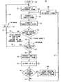
- FIG. 5is a simplified flow chart describing an aspect of internal seeing eye mouse operation related to the operation of the hold feature when used in conjunction with a feature called prediction;
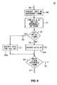
- FIG. 6is a simplified portion of a modification of the flow chart of FIG. 5 and illustrates the velocity detection method of invoking the hold feature
- FIG. 7is a perspective view of a plotted correlation surface that has good concavity.
- An optical mouseimages as an array of pixels the spatial features of generally any micro textured or micro detailed work surface below the mouse.
- the photo detector responsesare digitized and may be stored as a frame into memory.
- Motionproduces successive frames of translated patterns of pixel information, which may be compared by autocorrelation to ascertain the direction and amount of movement.
- a hold featuresuspends the production of movement signals to the computer, allowing the mouse to be physically relocated on the work surface without disturbing the position on the screen of the pointer. This may be needed if the operator runs out of room to physically move the mouse further, but the screen pointer still needs to go further.
- the hold featuremay be implemented with an actual button, a separate proximity detector or by detecting the presence of a characteristic condition in the digitized data, such as loss of correlation or velocity in excess of a selected limit.
- a convenient place for an actual hold buttonis along the sides of the mouse near the bottom, where the thumb and the opposing ring finger grip the mouse. The gripping force used to lift the mouse engages the hold function. Hold may incorporate a brief delay upon either the release of the hold button, detection of proper proximity or the return of reasonable digitized values. During that delay any illumination control or AGC servo loops stabilize. A new reference frame may taken prior to the resumption of motion detection.
- a solution to the problem of replacing a conventional mechanical mouse with an optical counterpartis to optically detect motion by directly imaging, as an array of pixels, the various particular spatial features of a work surface below the mouse, much as human vision is believed to do.
- this work surfacemay be almost any flat surface; in particular, the work surface need not be a mouse pad, special or otherwise.
- the work surface below the imaging mechanismmay be illuminated from the side, say, with an infrared (IR) light emitting diode (LED).
- IRinfrared
- LEDlight emitting diode
- a surprisingly wide variety of surfacescreate a rich collection of highlights and shadows when illuminated with a suitable angle of incidence. That angle is generally low, say, on the order of five to twenty degrees, and we shall term it a “grazing” angle of incidence.
- Paper, wood, formica and painted surfacesall work well; about the only surface that does not work is smooth glass (unless it is covered with fingerprints!). The reason these surfaces work is that they possess a micro texture, which in some cases may not be perceived by the unaided human senses.
- IR light reflected from the micro textured surfaceis focused onto a suitable array (say, 16 ⁇ 16 or 24 ⁇ 24) of photo detectors.
- the LEDmay be continuously on with either a steady or variable amount of illumination servoed to maximize some aspect of performance (e.g., the dynamic range of the photo detectors in conjunction with the albedo of the work surface).
- a charge accumulation mechanism coupled to the photo detectorsmay be “shuttered” (by current shunting switches) and the LED pulsed on and off to control the exposure by servoing the average amount of light. Turning the LED off also saves power; an important consideration in battery operated environments.
- the responses of the individual photo detectorsare digitized to a suitable resolution (say, six or eight bits) and stored as a frame into corresponding locations within an array of memory. Having thus given our mouse an “eye”, we are going to further equip it to “see” movement by performing comparisons with successive frames.
- the size of the image projected onto the photo detectorsmay be a slight magnification of the original features being imaged, say, by two to four times.
- the photo detectorsare small enough it may be possible and desirable to dispense with magnification.
- the size of the photo detectors and their spacingmay be such that there is much more likely to be one or several adjacent photo detectors per image feature, rather than the other way around.
- the pixel size represented by the individual photo detectorscorresponds to a spatial region on the work surface of a size that is generally smaller than the size of a typical spatial feature on that work surface, which might be a strand of fiber in a cloth covering a mouse pad, a fiber in a piece of paper or cardboard, a microscopic variation in a painted surface, or an element of an embossed micro texture on a plastic laminate.
- the overall size of the array of photo detectorsis preferably large enough to receive the images of several features. In this way, images of such spatial features produce translated patterns of pixel information as the mouse moves.
- the number of photo detectors in the array and the frame rate at which their contents are digitized and capturedcooperate to influence how fast the seeing-eye mouse can be moved over the work surface and still be tracked. Tracking may be accomplished by comparing a newly captured sample frame with a previously captured reference frame to ascertain the direction and amount of movement.
- One way that may be doneis to shift the entire content of one of the frames by a distance of one pixel (corresponds to a photo detector), successively in each of the eight directions allowed by a one pixel offset trial shift (one over, one over and one down, one down, one up, one up and one over, one over in the other direction, etc.).
- the trial shift with the least differencecan be taken as an indication of the motion between the two frames. That is, it provides a raw F/B and L/R.
- the raw movement informationmay be scaled and or accumulated to provide display pointer movement information ( ⁇ x and ⁇ y) of a convenient granularity and at a suitable rate of information exchange.
- One edge, or two adjacent edgeswill be unmatched, as it were. Pixel locations along the unmatched edges will not contribute to the corresponding correlation (i.e., for that particular shift), but all the others will. And those others are a substantial number of pixels, which gives rise to a very good signal to noise ratio.
- the correlationproduces nine “correlation values”, which may be derived from a summing of squared differences for all pixel locations having spatial correspondence (i.e., a pixel location in one frame that is indeed paired with a pixel location in the other frame—unmatched edges won't have such pairing).
- the shiftingmay be accomplished by addressing offsets to memories that can output an entire row or column of an array at one time.
- Dedicated arithmetic circuitrymay be connected to the memory array that contains the reference frame being shifted and to the memory array that contains the sample frame.
- the formulation of the correlation value for a particular trial shiftis accomplished very quickly.
- the best mechanical analogyis to imagine a transparent (reference) film of clear and dark patterns arranged as if it were a checker board, except that the arrangement is perhaps random. Now imagine that a second (sample) film having the same general pattern is overlaid upon the first, except that it is the negative image (dark and clear are interchanged).
- the pairis aligned and held up to the light.
- the positioning that admits the least lightis the best correlation. If the negative image pattern of the reference film is a square or two displaced from the image of the sample film, the positioning admits the least light will be one that matches that displacement. We take note of which displacement admits the least light; for the mouse we notice the positioning with the best correlation and say that the mouse moved that much. That, in effect, is what happens within an integrated circuit (IC) having photo detectors, memory and arithmetic circuits arranged to implement the image correlation and tracking technique we are describing.
- ICintegrated circuit
- each new collection of nine (or twenty-five) correlation values (for collections at t 1 , t i-1 , etc.) that originates from a new image at the photo detectors (a next sample frame)should contain a satisfactory correlation.
- several successive collections of comparison framescan usually be obtained from the (16 ⁇ 16) reference frame taken at t 0 . What allows this to be done is maintaining direction and displacement data for the most recent motion (which is equivalent to knowing velocity and time interval since the previous measurement).
- predictionof how to (permanently!) shift the collection of pixels in the reference frame so that for the next sample frame a “nearest neighbor” can be expected to correlate.
- This shifting to accommodate predictionthrows away, or removes, some of the reference frame, reducing the size of the reference frame and degrading the statistical quality of the correlations.
- edge of the shifted and reduced reference framebegins to approach the center of what was the original reference frame it may be time to take a new reference frame.
- This manner of operationmay be termed “prediction” and could also be used with comparison frames that are 5 ⁇ 5 and an extended “near neighbor” (null, two over/one up, one over/two up, one over/one up, two over, one over, . . . ) algorithm.
- the benefits of predictionare a speeding up of the tracking process by streamlining internal correlation procedure (avoiding the comparison of two arbitrarily related 16 ⁇ 16 arrays of data) and a reduction of the percentage of time devoted to acquiring reference frames.
- the mousemay have another button that suspends the production of movement signals to the computer, allowing the mouse to be physically relocated on the work surface without disturbing the position on the screen of the pointer. This may be needed if the operator runs out of room to physically move the mouse further, but the screen pointer still needs to go further. This may happen, say, in a UNIX system employing a display system known as “Single Logical Screen” (SLS) where perhaps as many as four monitors are arranged to each display some subportion of the overall “screen”. If these monitors were arranged as one high by four across, then the left to right distance needed for a single corresponding maximal mouse movement would be much wider than usually allowed for.
- SLSSingle Logical Screen
- the usual maneuver executed by the operator for, say, an extended rightward excursionis to simply pick the mouse up at the right side of the work surface (a mouse pad, or perhaps simply the edge of clearing on an otherwise cluttered surface of his desk), set it down on the left and continue to move it to the right.
- What is neededis a way to keep the motion indicating signals from undergoing spurious behavior during this maneuver, so that the pointer on the screen behaves in an expected and non-obnoxious manner.
- the function of the “hold” buttonmay be performed automatically by a proximity sensor on the underside of the mouse that determines that the mouse is not in contact with the work surface, or by noticing that all or a majority of the pixels in the image have “gone dark” (it's actually somewhat more complicated than that—we shall say more about this idea in the next paragraph). Without a hold feature, there may be some slight skewing of the image during the removal and replacement of the mouse, owing either: (a) to a tilting of the field of view as the mouse is lifted; or (b) to some perverse mistake where frames for two disparate and widely separated spatial features imaged at very different times during the removal and replacement are nevertheless taken as representing a small distance between two frames for the same feature.
- a convenient place for an actual hold buttonis along the sides of the mouse near the bottom, where the thumb and the opposing ring finger would grip the mouse to lift it up. A natural increase in the gripping force used to lift the mouse would also engage the hold function.
- a hold featuremay incorporate an optional brief delay upon either the release of the hold button, detection of proper proximity or the return of reasonable digitized values. During that delay any illumination control servo loops or internal automatic gain controls would have time to stabilize and a new reference frame would be taken prior to the resumption of motion detection.
- Another method for invoking or initiating a hold featureis to simply notice that the mouse is moving faster than a certain threshold velocity (and is thus presumably experiencing an abrupt retrace motion in a maneuver intended to translate the screen pointer further than the available physical space within which the mouse is operating). Once the velocity threshold is exceeded the motion indicating signals that would otherwise be associated with that movement are suppressed until such time as the velocity drops below a suitable level.
- FIG. 1wherein is shown a simplified representation of a cut-away side view of a prior art imaging and navigation arrangement 1 that is generally of the type described by the incorporated Patents.
- An LED 2which may be an IR LED, emits light which is projected by lens 3 (which instead of being separate may be an integral part of the LED's package), through orifice 13 in bottom surface 6 and onto a region 4 that is part of a work surface 5 .
- the average angle of incidenceis preferably within the range of five to twenty degrees.
- the orifice 13might include a window that is transparent for the light from LED 2 , and which would serve to keep dust, dirt or other contamination out of the innards of the seeing eye mouse.
- Work surface 5might belong to a special object, such as a mouse pad, or more generally, it will not, and might be the surface of nearly anything except smooth glass.
- suitable materialsinclude, but are not limited to, paper, cloth, laminated plastic tops, painted surfaces, frosted glass (smooth side down, thank you), desk pads, real wood, fake wood, etc.
- any micro textured surface having features whose size falls within the range of 5 to 500 micronswill do.
- micro textured surfacesare most effective when done from the side, as this accentuates the pattern of highlights and shadows produced by surface height irregularities.
- Suitable angles of incidence for illuminationcover the range of about five to twenty degrees.
- a very smooth or flat surfacee.g., one that has been ground and polished
- having simple variations in reflectivity owing to (micro scale) compositional variationworks, too.
- the angle of incidence for the illuminationcould approach ninety degrees, since the urge to create shadows goes away.
- An image of the illuminated region 4is projected through an optical window 9 in package portion 8 a of an integrated circuit and onto an array 10 of photo detectors. This is done with the aid of lens 7 .
- the package portion 8 amight also dispense with separate window 9 and lens 7 by combining them into one and the same element.
- the photo detectorsmay comprise a square array of, say, 12 to 24 detectors on a side, each detector being a photo transistor whose photo sensitive region is 45 by 45 microns and of 60 microns center to center spacing.
- the photo transistorscharge capacitors whose voltages are subsequently digitized and stored in a memory.
- the array 10is fabricated onto a portion of an integrated circuit die 12 affixed by an adhesive 11 onto package portion 8 b .
- any of the details of how the integrated circuit is held in place(probably by a printed circuit board), the shape or composition of the lenses, or of how the lenses are mounted; it is clear that those things are doable in a conventional manner.
- the general level of illumination of region 4may be controlled by noticing the output levels of the photo detectors and adjusting the intensity of light issuing from the LED 2 . This could be either continuous control or pulse width modulation, or some combination of both.
- FIG. 2is a bottom view of a mouse 14 constructed in accordance with the invention.
- this bottom view of this particular seeing eye mouse 14looks very similar to the bottom view of a particular conventional mouse from Hewlett-Packard Co., to wit: the C1413A.
- the major differenceis that where there ought to be a ball there is a protective lens or window 16 that is transparent to IR light. This is the omitted transparent window in orifice 13 that was mentioned in the description of FIG. 1 .
- the usual rotatable annulusthat serves as a removable retainer to allow access to the ball for cleaning or replacement.
- What is shown in the figureis the underside 15 of the mouse 14 (corresponds to 6 in FIG. 1 ), low friction glides 19 and connecting cable 17 with its strain relief 18 .
- our seeing eye mouse 14could be a cordless mouse, as well, with an optical or radio communication link to the computer.
- the hold featureis an aspect of seeing eye mouse operation that suspends the production of movement information or signals to the computer when it is determined that the mouse is not suitably proximate to the work surface whose spatial features are being tracked. This allows the seeing eye mouse to be picked up, translated and set back down, or, as we shall term such an operation, “swiped” across the work surface.
- the seeing eye mouse 14 in FIG. 3includes at least one hold button 24 located in side skirt 20 near the bottom surface 15 so as to be beneath the right thumb or the left ring finger, depending upon which hand the operator is using. There may be another symmetrically located button on the other side (not shown) that would contact either the left thumb or the right ring finger.
- the mouse 14conventionally includes a surface 21 which nestles in the palm of the hand, and first and second “regular” mouse buttons 22 and 23 that are actuated by the index and middle fingers. These operate in their normal fashion.
- buttons 24are activated by a natural increase in the gripping force needed to pick the mouse 14 up during a swipe. When one or both of these button are pressed the hold feature is activated. For the duration of the hold the sending of motion signals to the computer is suspended. When the hold is over (the buttons are released) a new reference frame is taken before any new motion signals are sent to the computer. This allows swiping, and has the advantage that the user has the ability to expressly force the onset of the hold feature.
- the hold featurecould also be automatically activated by the action of a separate proximity sensor on the bottom of the mouse. This is what is shown in FIG. 4 , where a shouldered aperture 26 in the base 6 receives a shouldered plunger 25 made captive by the lever arm of a switch 28 above.
- the switch 28is activated by movement of the plunger 25 , such that when the plunger moves significantly in the direction of arrow 27 the hold feature is activated.
- the exact nature of the separate proximity sensoris a matter of choice, and while it could be a simple as the micro switch 28 operated by the weight of the mouse through the plunger 25 , other, non-mechanical, methods are also possible.
- Yet another way to automatically activate and deactivate the hold featureis to examine the nature of the digitized data of the array 10 of photo detectors. When the outputs of the photo detectors become sufficiently uniform it may be surmised that there is no longer an image with variations projected onto the array 10 of photo detectors. This uniformity will reveal itself by producing a correlation surface that is flat, or nearly so. Rather than separately detecting uniform levels (which would use hardware not otherwise present), we prefer instead to examine the shape of the correlation surface, (which surface we need for other reasons, anyway). The most probable cause of a flat correlation surface is that the mouse has been picked up. This mode of operation may require that there be a fairly narrow depth of field, lest there occur undue delay in activating the hold.
- step 31ACQUIRE A REFERENCE FRAME. This refers to illuminating the LED 2 and storing a collection of digitized photo detector values into an array of memory (not shown).
- step 32ACQUIRE A SAMPLE FRAME. This refers to the same actions, except that the data is stored in a different array of memory, and may reflect mouse motion relative to where it was when step 31 was performed.
- COMPUTE CORRELATION VALUESthe nine (or perhaps twenty-five) correlation values are quickly computed by some heavy duty dedicated arithmetic hardware assisted by automatic address translation and a very wide path out of the memory arrays.
- IS THE CORRELATION SURFACE SUITABLY CONCAVE?the nature of the correlation surface described by the collection of correlation values computed in step 33 is examined. We want to know if it is shaped like a bowl, and if so, “how much water will it hold,” so to speak.
- path 36takes us to the optional step 37 : IS THE HOLD BUTTON PRESSED?; more about that in the next paragraph. Otherwise, we have a flat correlation surface, or a “bad bowl,” and proceed along path 35 to optional step 42 , DELAY.
- qualifier 34e.g., extreme velocity, a suddenly featureless work surface, and, an airborne mouse. In the absence of an explicit HOLD button, we will rely upon exit path 35 to provide proper seeing eye mouse behavior by suppressing motion signals to the computer during the airborne portion of a swiping operation.
- optional qualifier 37is present, and it is there that the status (pressed or not) of the HOLD 24 button is determined. The case where it is pressed is treated the same as that for a bad bowl at qualifier 34 . That is, path 38 is taken, which also leads to optional step 42 .
- Optional step 42provides a delay which may be useful in several ways. First, if there is a swipe in progress, then it takes some time, and by not imagining during that time some battery power can be saved. Also, suppose that the nature of the delay is slightly more complex than a pause in the motion of a moving finger on the flow chart. Suppose that the ACQUIRE REFERENCE FRAME step 31 were influenced by there having been a delay at step 42 , in that part way through the delay an illumination level control operation is initiated. This could allow time for re-adjustment of illumination levels, and so forth. Whether or not there is a DELAY at optional step 42 , path 43 leads back to step 31 , where another motion detection cycle begins.
- step 40PREDICT SHIFT IN REFERENCE FRAME.
- the predicted shiftcan be taken as the amount of movement corresponding to the correlation at the preceding step 34 .
- the next step 44is OUTPUT ⁇ X & ⁇ Y. It is here that we take note of how much mouse motion there has been since the last measurement cycle. The amount of shift needed to attain correlation is the desired amount. These values may be found by noticing which comparison frame actually correlated (assuming no interpolation). These “raw” ⁇ X and ⁇ Y motion values may be accumulated into running values that are sent to the computer at a lower rate than that at which the raw values of step 44 are produced.
- Step 49SHIFT REFERENCE FRAME, performs the actual permanent shift of the values in the memory array representing the reference frame. The shift is by the prediction amount, and data shifted away is lost. Following the shifting of the reference frame path 50 returns to step 32 , ACQUIRE A SAMPLE FRAME, where the next measurement cycle begins.
- FIG. 6wherein is shown a simplified flow chart segment 50 that shows how to replace step 44 of the flow chart 29 in FIG. 5 with steps 51 - 55 .
- the purpose for doing thisis similar to the various manners of hold operation already described, and may be used in conjunction therewith, or instead thereof.
- the general idea of the modification represented by FIG. 6is to outfox the computer by either not sending any updated information by skipping step 55 A or (optionally, with step 55 B) sending zeros for ⁇ X and ⁇ Y, even when that is not true. This is done whenever step 52 ascertains that the rate of mouse motion exceeds, say, three to six inches per second.
- Step 51represents anything in the old step 44 over and above the actual communication to the computer of the values ⁇ X and ⁇ Y.
- a tricky example of this differencemight be an internal accumulation of motion that has not yet be dispatched to the computer, owing to a higher internal motion measurement cycle rate for the seeing eye mouse than the information exchange rate with the computer. Now, it may well be the case that in some systems this accumulated information is used for internal mouse purposes other than strictly for keeping the computer informed. If so, then it would need to be preserved, for all that qualifier 52 , path 53 (and bypassed step 55 A) need to accomplish is NOT tell the computer there has been motion; we want to fool the computer but without making the mouse lose its mind.
- FIG. 7It is a plot 56 of a near neighbor (5 ⁇ 5) correlation surface 57 having a suitable concavity.
- the two horizontal axes 58 and 59represent the X and Y axes of mouse motion; the units indicated along the axes are pixels.
- Drawn onto the plane of the axes 58 and 59are smoothed and interpolated contour lines 60 intended to further indicate the shape of the correlation surface directly above.
- the vertical axis 61a measure of correlation expressed in essentially arbitrary units.
Landscapes
- Engineering & Computer Science (AREA)
- General Engineering & Computer Science (AREA)
- Theoretical Computer Science (AREA)
- Human Computer Interaction (AREA)
- Physics & Mathematics (AREA)
- General Physics & Mathematics (AREA)
- Position Input By Displaying (AREA)
- Image Input (AREA)
- Length Measuring Devices By Optical Means (AREA)
Abstract
Description
Claims (7)
Priority Applications (1)
| Application Number | Priority Date | Filing Date | Title |
|---|---|---|---|
| US11/147,838US7791590B1 (en) | 1995-10-06 | 2005-06-08 | Optical mouse with uniform level detection |
Applications Claiming Priority (5)
| Application Number | Priority Date | Filing Date | Title |
|---|---|---|---|
| US08/540,355US5786804A (en) | 1995-10-06 | 1995-10-06 | Method and system for tracking attitude |
| US09/052,046US6281882B1 (en) | 1995-10-06 | 1998-03-30 | Proximity detector for a seeing eye mouse |
| US09/753,805US6433780B1 (en) | 1995-10-06 | 2001-01-02 | Seeing eye mouse for a computer system |
| US10/217,725US6950094B2 (en) | 1998-03-30 | 2002-08-12 | Seeing eye mouse for a computer system |
| US11/147,838US7791590B1 (en) | 1995-10-06 | 2005-06-08 | Optical mouse with uniform level detection |
Related Parent Applications (1)
| Application Number | Title | Priority Date | Filing Date |
|---|---|---|---|
| US10/217,725ContinuationUS6950094B2 (en) | 1995-10-06 | 2002-08-12 | Seeing eye mouse for a computer system |
Publications (1)
| Publication Number | Publication Date |
|---|---|
| US7791590B1true US7791590B1 (en) | 2010-09-07 |
Family
ID=26730102
Family Applications (12)
| Application Number | Title | Priority Date | Filing Date |
|---|---|---|---|
| US10/217,725Expired - LifetimeUS6950094B2 (en) | 1995-10-06 | 2002-08-12 | Seeing eye mouse for a computer system |
| US11/022,183Expired - Fee RelatedUS7652661B2 (en) | 1995-10-06 | 2004-12-23 | “Seeing eye” mouse for computer system |
| US11/147,838Expired - Fee RelatedUS7791590B1 (en) | 1995-10-06 | 2005-06-08 | Optical mouse with uniform level detection |
| US11/154,008Expired - Fee RelatedUS7907120B2 (en) | 1995-10-06 | 2005-06-15 | Optical mouse with uniform level detection method |
| US11/154,007Expired - Fee RelatedUS7643007B2 (en) | 1995-10-06 | 2005-06-15 | Method of operating an optical mouse |
| US11/614,958AbandonedUS20070103439A1 (en) | 1995-10-06 | 2006-12-21 | Method of operating an optical mouse |
| US11/929,606Expired - Fee RelatedUS7808485B2 (en) | 1995-10-06 | 2007-10-30 | Method of operating an optical mouse |
| US11/929,616Expired - Fee RelatedUS7800585B2 (en) | 1995-10-06 | 2007-10-30 | Method of operating an optical mouse |
| US12/634,245Expired - Fee RelatedUS8212778B2 (en) | 1995-10-06 | 2009-12-09 | Imaging and navigation arrangement for controlling a cursor |
| US13/034,242Expired - Fee RelatedUS8350812B2 (en) | 1995-10-06 | 2011-02-24 | Method and arrangement for tracking movement relative to a surface |
| US13/709,052Expired - Fee RelatedUS8896537B2 (en) | 1995-10-06 | 2012-12-09 | Optical navigation chip used in an optical mouse |
| US14/517,923Expired - Fee RelatedUS9280213B2 (en) | 1995-10-06 | 2014-10-20 | Optical navigation chip used in an optical mouse |
Family Applications Before (2)
| Application Number | Title | Priority Date | Filing Date |
|---|---|---|---|
| US10/217,725Expired - LifetimeUS6950094B2 (en) | 1995-10-06 | 2002-08-12 | Seeing eye mouse for a computer system |
| US11/022,183Expired - Fee RelatedUS7652661B2 (en) | 1995-10-06 | 2004-12-23 | “Seeing eye” mouse for computer system |
Family Applications After (9)
| Application Number | Title | Priority Date | Filing Date |
|---|---|---|---|
| US11/154,008Expired - Fee RelatedUS7907120B2 (en) | 1995-10-06 | 2005-06-15 | Optical mouse with uniform level detection method |
| US11/154,007Expired - Fee RelatedUS7643007B2 (en) | 1995-10-06 | 2005-06-15 | Method of operating an optical mouse |
| US11/614,958AbandonedUS20070103439A1 (en) | 1995-10-06 | 2006-12-21 | Method of operating an optical mouse |
| US11/929,606Expired - Fee RelatedUS7808485B2 (en) | 1995-10-06 | 2007-10-30 | Method of operating an optical mouse |
| US11/929,616Expired - Fee RelatedUS7800585B2 (en) | 1995-10-06 | 2007-10-30 | Method of operating an optical mouse |
| US12/634,245Expired - Fee RelatedUS8212778B2 (en) | 1995-10-06 | 2009-12-09 | Imaging and navigation arrangement for controlling a cursor |
| US13/034,242Expired - Fee RelatedUS8350812B2 (en) | 1995-10-06 | 2011-02-24 | Method and arrangement for tracking movement relative to a surface |
| US13/709,052Expired - Fee RelatedUS8896537B2 (en) | 1995-10-06 | 2012-12-09 | Optical navigation chip used in an optical mouse |
| US14/517,923Expired - Fee RelatedUS9280213B2 (en) | 1995-10-06 | 2014-10-20 | Optical navigation chip used in an optical mouse |
Country Status (1)
| Country | Link |
|---|---|
| US (12) | US6950094B2 (en) |
Cited By (5)
| Publication number | Priority date | Publication date | Assignee | Title |
|---|---|---|---|---|
| US20110141014A1 (en)* | 2009-12-16 | 2011-06-16 | Chung Shan Institute Of Science And Technology, Armaments Bureau, M.N.D | Movable touchpad with high sensitivity |
| US20120326965A1 (en)* | 2008-07-18 | 2012-12-27 | Apple Inc. | Methods and apparatus for processing combinations of kinematical inputs |
| US20130093678A1 (en)* | 1995-10-06 | 2013-04-18 | Pixart Imaging Inc. | Optical navigation chip used in an optical mouse |
| TWI501117B (en)* | 2012-10-22 | 2015-09-21 | Pixart Imaging Inc | Optical navigation device and lift detection method thereof |
| US20250291433A1 (en)* | 2022-05-26 | 2025-09-18 | Microsoft Technology Licensing, Llc | Mouse with integrated optical module |
Families Citing this family (121)
| Publication number | Priority date | Publication date | Assignee | Title |
|---|---|---|---|---|
| US9513744B2 (en) | 1994-08-15 | 2016-12-06 | Apple Inc. | Control systems employing novel physical controls and touch screens |
| US20090273574A1 (en)* | 1995-06-29 | 2009-11-05 | Pryor Timothy R | Programmable tactile touch screen displays and man-machine interfaces for improved vehicle instrumentation and telematics |
| US8228305B2 (en) | 1995-06-29 | 2012-07-24 | Apple Inc. | Method for providing human input to a computer |
| US7808479B1 (en) | 2003-09-02 | 2010-10-05 | Apple Inc. | Ambidextrous mouse |
| US8482535B2 (en) | 1999-11-08 | 2013-07-09 | Apple Inc. | Programmable tactile touch screen displays and man-machine interfaces for improved vehicle instrumentation and telematics |
| US8576199B1 (en) | 2000-02-22 | 2013-11-05 | Apple Inc. | Computer control systems |
| US6781570B1 (en)* | 2000-11-09 | 2004-08-24 | Logitech Europe S.A. | Wireless optical input device |
| US6664948B2 (en)* | 2001-07-30 | 2003-12-16 | Microsoft Corporation | Tracking pointing device motion using a single buffer for cross and auto correlation determination |
| US7656393B2 (en) | 2005-03-04 | 2010-02-02 | Apple Inc. | Electronic device having display and surrounding touch sensitive bezel for user interface and control |
| US11275405B2 (en) | 2005-03-04 | 2022-03-15 | Apple Inc. | Multi-functional hand-held device |
| US8171567B1 (en) | 2002-09-04 | 2012-05-01 | Tracer Detection Technology Corp. | Authentication method and system |
| US7358963B2 (en)* | 2002-09-09 | 2008-04-15 | Apple Inc. | Mouse having an optically-based scrolling feature |
| US6924812B2 (en)* | 2002-12-24 | 2005-08-02 | Intel Corporation | Method and apparatus for reading texture data from a cache |
| US7295186B2 (en)* | 2003-01-14 | 2007-11-13 | Avago Technologies Ecbuip (Singapore) Pte Ltd | Apparatus for controlling a screen pointer that distinguishes between ambient light and light from its light source |
| TW576535U (en)* | 2003-04-23 | 2004-02-11 | Sunplus Technology Co Ltd | Optical input apparatus capable of judging reflection surface characteristic |
| US6927759B2 (en)* | 2003-06-06 | 2005-08-09 | Unity Opto Technology Co., Ltd. | Optical mouse with uniform light projection |
| US20040252101A1 (en)* | 2003-06-12 | 2004-12-16 | International Business Machines Corporation | Input device that detects user's proximity |
| US7161585B2 (en)* | 2003-07-01 | 2007-01-09 | Em Microelectronic-Marin Sa | Displacement data post-processing and reporting in an optical pointing device |
| TWI244044B (en)* | 2003-09-26 | 2005-11-21 | Sunplus Technology Co Ltd | Method and device for controlling dynamic image capturing rate of an optical mouse |
| EP1520514A1 (en)* | 2003-10-02 | 2005-04-06 | Matsushita Electric Industrial Co., Ltd. | Optical biological information measuring apparatus and method |
| US7317447B2 (en)* | 2003-11-21 | 2008-01-08 | Avago Technologies Ecbu Id (Singapore) Pte Ltd | Pointing device with adaptive illumination level |
| TWI230890B (en)* | 2003-12-29 | 2005-04-11 | Pixart Imaging Inc | Handheld pointing device and method for estimating a displacement |
| US7221356B2 (en)* | 2004-02-26 | 2007-05-22 | Microsoft Corporation | Data input device and method for detecting an off-surface condition by a laser speckle size characteristic |
| JP5148996B2 (en) | 2004-03-12 | 2013-02-20 | インジェニア・テクノロジー・(ユーケイ)・リミテッド | Method and apparatus for creating and subsequently verifying authentic printed articles |
| EP1730675B1 (en) | 2004-03-12 | 2015-05-20 | Ingenia Holdings Limited | Authenticity verification methods, products and apparatuses |
| US7042575B2 (en)* | 2004-05-21 | 2006-05-09 | Silicon Light Machines Corporation | Speckle sizing and sensor dimensions in optical positioning device |
| US7773070B2 (en) | 2004-05-21 | 2010-08-10 | Cypress Semiconductor Corporation | Optical positioning device using telecentric imaging |
| US7268341B2 (en)* | 2004-05-21 | 2007-09-11 | Silicon Light Machines Corporation | Optical position sensing device including interlaced groups of photosensitive elements |
| US7285766B2 (en)* | 2004-05-21 | 2007-10-23 | Silicon Light Machines Corporation | Optical positioning device having shaped illumination |
| US20050259097A1 (en)* | 2004-05-21 | 2005-11-24 | Silicon Light Machines Corporation | Optical positioning device using different combinations of interlaced photosensitive elements |
| US20050259078A1 (en)* | 2004-05-21 | 2005-11-24 | Silicon Light Machines Corporation | Optical positioning device with multi-row detector array |
| TWI240207B (en)* | 2004-06-11 | 2005-09-21 | Sunplus Technology Co Ltd | Method and system for real-time determining abnormality of pixel values for captured image |
| US7521719B2 (en)* | 2004-08-13 | 2009-04-21 | Paul Steven Schranz | Light emitting and image sensing device and apparatus |
| GB2417592B (en)* | 2004-08-13 | 2006-07-26 | Ingenia Technology Ltd | Authenticity verification of articles |
| US20060055666A1 (en)* | 2004-09-14 | 2006-03-16 | Chong Tan S | Method for controlling illumination employed by a computer pointing peripheral and computer pointing peripheral |
| US7528824B2 (en)* | 2004-09-30 | 2009-05-05 | Microsoft Corporation | Keyboard or other input device using ranging for detection of control piece movement |
| US7732752B2 (en)* | 2004-09-30 | 2010-06-08 | Logitech Europe S.A. | Continuous base beneath optical sensor and optical homodyning system |
| US7405389B2 (en) | 2004-11-19 | 2008-07-29 | Silicon Light Machines Corporation | Dense multi-axis array for motion sensing |
| US7379049B2 (en) | 2004-12-13 | 2008-05-27 | Avago Technologies Ecbu Ip Pte Ltd | Apparatus for controlling the position of a screen pointer based on projection data |
| US7405727B2 (en)* | 2004-12-15 | 2008-07-29 | Em Microelectronic-Marin Sa | Lift detection mechanism for optical mouse sensor |
| US7619612B2 (en)* | 2004-12-20 | 2009-11-17 | Avago Technologies Ecbu Ip (Singapore) Pte. Ltd. | Pointing device with light source for providing visible light through a moveable puck |
| US7852317B2 (en) | 2005-01-12 | 2010-12-14 | Thinkoptics, Inc. | Handheld device for handheld vision based absolute pointing system |
| KR101484499B1 (en) | 2005-02-14 | 2015-01-20 | 존슨 앤드 존슨 비젼 케어, 인코포레이티드 | A method of producing ophthalmic lenses, an ophthalmic device, and a contact lens |
| US8081159B2 (en)* | 2005-02-24 | 2011-12-20 | Avago Technologies Ecbu Ip (Singapore) Pte. Ltd. | Programmable lift response for an optical navigation device |
| US20090237358A1 (en)* | 2005-03-08 | 2009-09-24 | Yuan-Jung Chang | Computer mouse and method of dynamical data transmission rate management therefor |
| US20060213997A1 (en)* | 2005-03-23 | 2006-09-28 | Microsoft Corporation | Method and apparatus for a cursor control device barcode reader |
| US7710397B2 (en) | 2005-06-03 | 2010-05-04 | Apple Inc. | Mouse with improved input mechanisms using touch sensors |
| US7268705B2 (en)* | 2005-06-17 | 2007-09-11 | Microsoft Corporation | Input detection based on speckle-modulated laser self-mixing |
| US7557795B2 (en)* | 2005-06-30 | 2009-07-07 | Microsoft Corporation | Input device using laser self-mixing velocimeter |
| US7898524B2 (en)* | 2005-06-30 | 2011-03-01 | Logitech Europe S.A. | Optical displacement detection over varied surfaces |
| JP5123181B2 (en) | 2005-07-27 | 2013-01-16 | インジェニア・テクノロジー・(ユーケイ)・リミテッド | Authenticity verification |
| US7283214B2 (en)* | 2005-10-14 | 2007-10-16 | Microsoft Corporation | Self-mixing laser range sensor |
| US7543750B2 (en)* | 2005-11-08 | 2009-06-09 | Microsoft Corporation | Laser velocimetric image scanning |
| US7505033B2 (en)* | 2005-11-14 | 2009-03-17 | Microsoft Corporation | Speckle-based two-dimensional motion tracking |
| US20070109267A1 (en)* | 2005-11-14 | 2007-05-17 | Microsoft Corporation | Speckle-based two-dimensional motion tracking |
| US7567235B2 (en) | 2005-12-12 | 2009-07-28 | Cypress Semiconductor Corporation | Self-aligning optical sensor package |
| US7765251B2 (en)* | 2005-12-16 | 2010-07-27 | Cypress Semiconductor Corporation | Signal averaging circuit and method for sample averaging |
| US7737948B2 (en) | 2005-12-20 | 2010-06-15 | Cypress Semiconductor Corporation | Speckle navigation system |
| CN101923647B (en) | 2005-12-23 | 2013-01-09 | 英根亚控股有限公司 | Optical authentication |
| US8077147B2 (en) | 2005-12-30 | 2011-12-13 | Apple Inc. | Mouse with optical sensing surface |
| US20090051651A1 (en)* | 2006-01-05 | 2009-02-26 | Han Sang-Hyun | Apparatus for remote pointing using image sensor and method of the same |
| GB2434442A (en)* | 2006-01-16 | 2007-07-25 | Ingenia Holdings | Verification of performance attributes of packaged integrated circuits |
| US7884801B1 (en) | 2006-02-16 | 2011-02-08 | Cypress Semiconductor Corporation | Circuit and method for determining motion with redundant comb-arrays |
| US7721609B2 (en) | 2006-03-31 | 2010-05-25 | Cypress Semiconductor Corporation | Method and apparatus for sensing the force with which a button is pressed |
| US7809035B2 (en)* | 2006-03-31 | 2010-10-05 | Cypress Semiconductor Corporation | Eye-safe laser navigation sensor |
| US7976387B2 (en)* | 2006-04-11 | 2011-07-12 | Avago Technologies General Ip (Singapore) Pte. Ltd. | Free-standing input device |
| US7492445B1 (en) | 2006-06-05 | 2009-02-17 | Cypress Semiconductor Corporation | Method and apparatus for robust velocity prediction |
| GB2440386A (en)* | 2006-06-12 | 2008-01-30 | Ingenia Technology Ltd | Scanner authentication |
| US7755604B2 (en) | 2006-06-19 | 2010-07-13 | Cypress Semiconductor Corporation | Optical navigation sensor with tracking and lift detection for optically transparent contact surfaces |
| US7777722B2 (en)* | 2006-06-23 | 2010-08-17 | Microsoft Corporation | Multi-mode optical navigation |
| US7728816B2 (en) | 2006-07-10 | 2010-06-01 | Cypress Semiconductor Corporation | Optical navigation sensor with variable tracking resolution |
| US8913003B2 (en) | 2006-07-17 | 2014-12-16 | Thinkoptics, Inc. | Free-space multi-dimensional absolute pointer using a projection marker system |
| KR100845321B1 (en)* | 2006-08-18 | 2008-07-10 | 주식회사 애트랩 | Optical navigation device and method of offset correction thereof. |
| US7742514B1 (en) | 2006-10-31 | 2010-06-22 | Cypress Semiconductor Corporation | Laser navigation sensor |
| US7514668B2 (en)* | 2006-12-19 | 2009-04-07 | Avago Technologies Ecbu Ip (Singapore) Pte. Ltd. | Optical navigation device that utilizes a vertical cavity surface emitting laser (VCSEL) configured to emit visible coherent light |
| US20080178103A1 (en)* | 2007-01-23 | 2008-07-24 | Robert Campbell | Copying data between computer systems |
| US9176598B2 (en) | 2007-05-08 | 2015-11-03 | Thinkoptics, Inc. | Free-space multi-dimensional absolute pointer with improved performance |
| WO2008156872A1 (en)* | 2007-06-21 | 2008-12-24 | The Johns Hopkins University | Manipulation device for navigating virtual microscopy slides/digital images and methods related thereto |
| US8314774B1 (en) | 2007-07-09 | 2012-11-20 | Cypress Semiconductor Corporation | Method and apparatus for quasi-3D tracking using 2D optical motion sensors |
| US8263921B2 (en) | 2007-08-06 | 2012-09-11 | Cypress Semiconductor Corporation | Processing methods for speckle-based motion sensing |
| WO2009029912A1 (en) | 2007-08-30 | 2009-03-05 | Microstrain, Inc. | Optical linear and rotation displacement sensor |
| TW200923734A (en)* | 2007-11-23 | 2009-06-01 | Sunplus Mmedia Inc | Coordinate positioning mouse having suspended positioning function |
| WO2009072240A1 (en)* | 2007-12-07 | 2009-06-11 | Panasonic Corporation | Electronic device |
| US8259069B1 (en) | 2008-01-11 | 2012-09-04 | Cypress Semiconductor Corporation | Speckle-based optical navigation on curved tracking surface |
| US8031176B1 (en) | 2008-01-22 | 2011-10-04 | Cypress Semiconductor Corporation | Optical navigation system using a single-package motion sensor |
| GB2461253B (en) | 2008-05-23 | 2012-11-21 | Ingenia Holdings Ltd | Linearisation of scanned data |
| US20100060567A1 (en)* | 2008-09-05 | 2010-03-11 | Microsoft Corporation | Controlling device operation relative to a surface |
| US8570194B2 (en) | 2008-09-05 | 2013-10-29 | Microsoft Corporation | Clutch-height adjustment in an optical tracking device |
| US8541727B1 (en) | 2008-09-30 | 2013-09-24 | Cypress Semiconductor Corporation | Signal monitoring and control system for an optical navigation sensor |
| US7723659B1 (en) | 2008-10-10 | 2010-05-25 | Cypress Semiconductor Corporation | System and method for screening semiconductor lasers |
| GB2466465B (en) | 2008-12-19 | 2011-02-16 | Ingenia Holdings | Authentication |
| GB2466311B (en) | 2008-12-19 | 2010-11-03 | Ingenia Holdings | Self-calibration of a matching algorithm for determining authenticity |
| US8711096B1 (en) | 2009-03-27 | 2014-04-29 | Cypress Semiconductor Corporation | Dual protocol input device |
| US9300834B2 (en)* | 2009-05-20 | 2016-03-29 | Dacuda Ag | Image processing for handheld scanner |
| US8339467B2 (en)* | 2010-03-25 | 2012-12-25 | Dacuda Ag | Synchronization of navigation and image information for handheld scanner |
| US8441696B2 (en) | 2009-05-20 | 2013-05-14 | Dacuda Ag | Continuous scanning with a handheld scanner |
| US8441695B2 (en)* | 2009-05-20 | 2013-05-14 | Dacuda Ag | Handheld scanner with high image quality |
| US8582182B2 (en)* | 2009-05-20 | 2013-11-12 | Dacuda Ag | Automatic sizing of images acquired by a handheld scanner |
| GB2476226B (en) | 2009-11-10 | 2012-03-28 | Ingenia Holdings Ltd | Optimisation |
| US8497840B2 (en)* | 2010-03-25 | 2013-07-30 | Dacuda Ag | Computer peripheral for scanning |
| US8864393B2 (en)* | 2010-06-21 | 2014-10-21 | Hewlett-Packard Development Company, L.P. | Media advance |
| KR101816721B1 (en)* | 2011-01-18 | 2018-01-10 | 삼성전자주식회사 | Sensing Module, GUI Controlling Apparatus and Method thereof |
| CN102959494B (en) | 2011-06-16 | 2017-05-17 | 赛普拉斯半导体公司 | An optical navigation module with capacitive sensor |
| US9182833B2 (en)* | 2011-11-14 | 2015-11-10 | Logitech Europe S.A. | Control system for multi-zone input device |
| US8896553B1 (en) | 2011-11-30 | 2014-11-25 | Cypress Semiconductor Corporation | Hybrid sensor module |
| EP3039617B1 (en) | 2013-08-31 | 2020-05-20 | ML Netherlands C.V. | User feedback for real-time checking and improving quality of scanned image |
| US10142522B2 (en) | 2013-12-03 | 2018-11-27 | Ml Netherlands C.V. | User feedback for real-time checking and improving quality of scanned image |
| EP4113457A1 (en) | 2014-01-07 | 2023-01-04 | ML Netherlands C.V. | Dynamic updating of composite images |
| EP3748953B1 (en) | 2014-01-07 | 2024-04-17 | ML Netherlands C.V. | Adaptive camera control for reducing motion blur during real-time image capture |
| US10484561B2 (en) | 2014-05-12 | 2019-11-19 | Ml Netherlands C.V. | Method and apparatus for scanning and printing a 3D object |
| TWI567593B (en)* | 2014-12-18 | 2017-01-21 | 明基電通股份有限公司 | Multi-functional mouse device and related method capable of automatically switching opertion modes |
| US9927884B2 (en)* | 2015-11-06 | 2018-03-27 | Pixart Imaging (Penang) Sdn. Bhd. | Non transitory computer readable recording medium for executing image processing method, and image sensing device applying the image processing method |
| US10627518B2 (en)* | 2017-06-02 | 2020-04-21 | Pixart Imaging Inc | Tracking device with improved work surface adaptability |
| CN111164548A (en)* | 2017-10-09 | 2020-05-15 | 惠普发展公司,有限责任合伙企业 | Removable button member for electronic printing device |
| TWI669638B (en)* | 2018-05-18 | 2019-08-21 | 致伸科技股份有限公司 | Mouse device |
| US11042992B2 (en) | 2018-08-03 | 2021-06-22 | Logitech Europe S.A. | Method and system for detecting peripheral device displacement |
| US11199910B2 (en)* | 2019-06-10 | 2021-12-14 | Pixart Imaging Inc. | Optical navigation device, optical navigation method and image processing system |
| US12100181B2 (en) | 2020-05-11 | 2024-09-24 | Magic Leap, Inc. | Computationally efficient method for computing a composite representation of a 3D environment |
| GB2594966B (en)* | 2020-05-13 | 2024-07-31 | Sony Interactive Entertainment Inc | Gaze tracking apparatus and systems |
| US11029765B1 (en)* | 2020-06-03 | 2021-06-08 | Pixart Imaging Inc. | Lift detection method for mouse and apparatus thereof |
| TWI786682B (en)* | 2021-04-22 | 2022-12-11 | 義隆電子股份有限公司 | Optical mouse and its control method |
Citations (116)
| Publication number | Priority date | Publication date | Assignee | Title |
|---|---|---|---|---|
| US3575505A (en) | 1968-07-30 | 1971-04-20 | Eastman Kodak Co | Automatic bias control |
| US3942022A (en) | 1974-10-25 | 1976-03-02 | Itek Corporation | Rapid response correlation type image motion sensor |
| US4136945A (en) | 1975-10-14 | 1979-01-30 | Eastman Kodak Company | Electrophotographic apparatus having compensation for changes in sensitometric properties of photoconductors |
| US4270143A (en) | 1978-12-20 | 1981-05-26 | General Electric Company | Cross-correlation video tracker and method |
| US4364035A (en) | 1981-05-18 | 1982-12-14 | Kirsch Steven T | Electro-optical mouse |
| US4390873A (en) | 1981-05-18 | 1983-06-28 | Kirsch Steven T | Electronic mouse |
| US4494201A (en) | 1981-04-27 | 1985-01-15 | Thomson-Csf | Moving-map display with recording on photographic film |
| US4521772A (en) | 1981-08-28 | 1985-06-04 | Xerox Corporation | Cursor control device |
| US4546347A (en) | 1981-05-18 | 1985-10-08 | Mouse Systems Corporation | Detector for electro-optical mouse |
| USD281776S (en) | 1983-11-21 | 1985-12-17 | Illinois Tool Works Inc. | Remote control hemisphere switch |
| US4578674A (en) | 1983-04-20 | 1986-03-25 | International Business Machines Corporation | Method and apparatus for wireless cursor position control |
| US4631400A (en) | 1984-01-20 | 1986-12-23 | California Institute Of Technology | Correlating optical motion detector |
| US4647771A (en) | 1983-12-05 | 1987-03-03 | Nissin Kohki Co. Ltd. | Optical mouse with X and Y line patterns on separate planes |
| US4682159A (en) | 1984-06-20 | 1987-07-21 | Personics Corporation | Apparatus and method for controlling a cursor on a computer display |
| US4712101A (en) | 1984-12-04 | 1987-12-08 | Cheetah Control, Inc. | Control mechanism for electronic apparatus |
| US4723297A (en) | 1984-09-27 | 1988-02-02 | Siemens Aktiengesellschaft | Method for automatic correction of character skew in the acquisition of a text original in the form of digital scan results |
| US4736191A (en) | 1985-08-02 | 1988-04-05 | Karl E. Matzke | Touch activated control method and apparatus |
| US4751505A (en) | 1986-06-23 | 1988-06-14 | Xerox Corporation | Optical mouse |
| US4754268A (en) | 1984-10-13 | 1988-06-28 | Mitsuboshi Belting Ltd. | Wireless mouse apparatus |
| US4794384A (en) | 1984-09-27 | 1988-12-27 | Xerox Corporation | Optical translator device |
| US4797544A (en) | 1986-07-23 | 1989-01-10 | Montgomery James R | Optical scanner including position sensors |
| US4799055A (en)* | 1984-04-26 | 1989-01-17 | Symbolics Inc. | Optical Mouse |
| US4804949A (en) | 1987-03-20 | 1989-02-14 | Everex Ti Corporation | Hand-held optical scanner and computer mouse |
| USD302010S (en) | 1986-07-21 | 1989-07-04 | Itac Systems, Inc. | Computer cursor control |
| US4856785A (en) | 1983-03-01 | 1989-08-15 | Williams Electronics, Inc. | Optical dual function joystick |
| US4857903A (en) | 1986-05-06 | 1989-08-15 | Summagraphics Corporation | Electro-optical mouse with improved resolution for compensation of optical distortion |
| US4906843A (en) | 1987-12-31 | 1990-03-06 | Marq Technolgies | Combination mouse, optical scanner and digitizer puck |
| US4920260A (en) | 1988-08-30 | 1990-04-24 | Msc Technologies, Inc. | Detector system for optical mouse |
| US4922236A (en) | 1988-04-25 | 1990-05-01 | Richard Heady | Fiber optical mouse |
| US4949080A (en) | 1988-12-12 | 1990-08-14 | Mikan Peter J | Computer keyboard control accessory |
| US4951214A (en) | 1988-11-18 | 1990-08-21 | Texas Instruments Incorporated | Method for passively determining the relative position of a moving observer with respect to a stationary object |
| US4959721A (en) | 1988-08-06 | 1990-09-25 | Deutsche Itt Industries Gmbh | Remote control system with menu driven function selection |
| US4970557A (en) | 1987-09-02 | 1990-11-13 | Sharp Kabushiki Kaisha | Electrophotographic apparatus controlling image quality according to condition of deterioration |
| USD315896S (en) | 1989-04-20 | 1991-04-02 | Northern Telecom Limited | Keypad |
| US5023922A (en) | 1985-06-07 | 1991-06-11 | Soricon Corporation | Optical character reader |
| US5045843A (en) | 1988-12-06 | 1991-09-03 | Selectech, Ltd. | Optical pointing device |
| US5089712A (en) | 1989-06-08 | 1992-02-18 | Hewlett-Packard Company | Sheet advancement control system detecting fiber pattern of sheet |
| US5142506A (en) | 1990-10-22 | 1992-08-25 | Logitech, Inc. | Ultrasonic position locating method and apparatus therefor |
| US5149980A (en) | 1991-11-01 | 1992-09-22 | Hewlett-Packard Company | Substrate advance measurement system using cross-correlation of light sensor array signals |
| US5185673A (en) | 1991-06-12 | 1993-02-09 | Hewlett-Packard Company | Automated image calibration |
| EP0572009A1 (en) | 1992-05-27 | 1993-12-01 | Spacelabs Medical, Inc. | Scanning system for touch screen keyboards |
| US5272503A (en) | 1992-09-02 | 1993-12-21 | Xerox Corporation | Replaceable sub-assemblies for electrostatographic reproducing machines |
| US5274361A (en) | 1991-08-15 | 1993-12-28 | The United States Of America As Represented By The Secretary Of The Navy | Laser optical mouse |
| US5285242A (en) | 1992-03-31 | 1994-02-08 | Minolta Camera Kabushiki Kaisha | Image forming apparatus controlled according to changing sensitivity of photoconductor |
| US5296838A (en) | 1991-04-22 | 1994-03-22 | Digital Stream Corp. | Wireless input system for computer |
| US5298919A (en) | 1991-08-02 | 1994-03-29 | Multipoint Technology Corporation | Multi-dimensional input device |
| US5347275A (en) | 1991-10-03 | 1994-09-13 | Lau Clifford B | Optical pointer input device |
| US5349371A (en) | 1991-06-04 | 1994-09-20 | Fong Kwang Chien | Electro-optical mouse with means to separately detect the changes in contrast ratio in X and Y directions |
| US5355146A (en) | 1990-03-05 | 1994-10-11 | Bmc Micro-Industries Ltd. | Multi-directional hand scanner and mouse |
| US5363120A (en) | 1987-10-14 | 1994-11-08 | Wang Laboratories, Inc. | Computer input device using orientation sensor |
| US5367315A (en) | 1990-11-15 | 1994-11-22 | Eyetech Corporation | Method and apparatus for controlling cursor movement |
| US5388059A (en) | 1992-12-30 | 1995-02-07 | University Of Maryland | Computer vision system for accurate monitoring of object pose |
| EP0645732A1 (en) | 1993-09-24 | 1995-03-29 | SINTECNA S.r.l. | Device for pointing the cursor on the screen of interactive systems |
| US5440144A (en) | 1992-11-06 | 1995-08-08 | Deutsche Forschungsanstalt Fur Luft-Und Raumfahrt E.V. | Apparatus for the three-dimensional determination of flows |
| US5450126A (en) | 1989-10-17 | 1995-09-12 | Mitsubishi Denki Kabushiki Kaisha | Image blur correcting apparatus |
| US5456256A (en) | 1993-11-04 | 1995-10-10 | Ultra-Scan Corporation | High resolution ultrasonic imaging apparatus and method |
| US5463387A (en) | 1991-12-27 | 1995-10-31 | Nissin Kohki Co., Ltd. | Optical mouse and resin lens unit |
| US5471542A (en) | 1993-09-27 | 1995-11-28 | Ragland; Richard R. | Point-of-gaze tracker |
| US5479011A (en) | 1992-12-18 | 1995-12-26 | Spectra-Physics Scanning Systems, Inc. | Variable focus optical system for data reading |
| US5490039A (en)* | 1993-11-24 | 1996-02-06 | Dell Usa, L.P. | Integrated mouse tray and mouse for portable computer having cavity therefore |
| US5491540A (en) | 1994-12-22 | 1996-02-13 | Hewlett-Packard Company | Replacement part with integral memory for usage and calibration data |
| US5497150A (en) | 1993-04-05 | 1996-03-05 | Smk Corporation | Image scanner |
| US5504319A (en) | 1994-02-09 | 1996-04-02 | Symbol Technologies, Inc. | Method and system for bar code acquisition |
| US5510603A (en) | 1992-05-26 | 1996-04-23 | United Parcel Service Of America, Inc. | Method and apparatus for detecting and decoding information bearing symbols encoded using multiple optical codes |
| GB2272763B (en) | 1992-11-14 | 1996-04-24 | Univ Sheffield | Device and method for determining movement |
| US5517211A (en)* | 1992-05-14 | 1996-05-14 | Kwang-Chien; Fong | Optical signal detector for an electro-optical mouse |
| US5525764A (en) | 1994-06-09 | 1996-06-11 | Junkins; John L. | Laser scanning graphic input system |
| US5530455A (en)* | 1994-08-10 | 1996-06-25 | Mouse Systems Corporation | Roller mouse for implementing scrolling in windows applications |
| US5532476A (en) | 1994-12-21 | 1996-07-02 | Mikan; Peter J. | Redundant indicator for detecting neutral position of joystick member |
| US5546128A (en) | 1991-08-20 | 1996-08-13 | Mitsubishi Denki Kabushiki Kaisha | Exposure control apparatus including a spatial light modulator |
| US5557440A (en) | 1994-01-05 | 1996-09-17 | Microsoft Corporation | Noise-insensitive optoencoding techniques with compensation for device variations |
| US5558329A (en) | 1995-03-01 | 1996-09-24 | Liu; William S. Y. | Photoelectric digitized joystick |
| US5561445A (en) | 1992-11-09 | 1996-10-01 | Matsushita Electric Industrial Co., Ltd. | Three-dimensional movement specifying apparatus and method and observational position and orientation changing apparatus |
| US5561543A (en) | 1994-05-02 | 1996-10-01 | Kabushikikaisha Wacom | Information input system by attitude detection of manual implement |
| US5563631A (en) | 1993-10-26 | 1996-10-08 | Canon Kabushiki Kaisha | Portable information apparatus |
| US5574480A (en) | 1994-06-07 | 1996-11-12 | Kensington Microware Limited | Computer pointing device |
| US5574479A (en) | 1994-01-07 | 1996-11-12 | Selectech, Ltd. | Optical system for determining the roll orientation of a remote unit relative to a base unit |
| US5576529A (en) | 1986-08-08 | 1996-11-19 | Norand Technology Corporation | Hand-held optically readable information set reader focus with operation over a range of distances |
| US5578817A (en) | 1992-10-05 | 1996-11-26 | Logitech, Inc. | Pointing device utilizing a photodetector array and controlled by a human finger contacting a prism |
| US5577848A (en) | 1992-08-24 | 1996-11-26 | Bowen; James H. | Light controlled touch pad for cursor and selection control on a computer display |
| US5578813A (en) | 1995-03-02 | 1996-11-26 | Allen; Ross R. | Freehand image scanning device which compensates for non-linear movement |
| US5617312A (en) | 1993-11-19 | 1997-04-01 | Hitachi, Ltd. | Computer system that enters control information by means of video camera |
| US5627565A (en) | 1994-05-26 | 1997-05-06 | Alps Electric Co., Ltd. | Space coordinates detecting device and input apparatus using same |
| US5644126A (en) | 1994-05-20 | 1997-07-01 | Kabushikikaisha Wacom | Manual implement for inputting incremental information by attitude control |
| US5644337A (en) | 1995-06-06 | 1997-07-01 | Zenith Electronics Corporation | Trackball having single emitter-detector detecting chopper wheel direction |
| US5680157A (en) | 1992-08-10 | 1997-10-21 | Logitech, Inc. | Pointing device with differential optomechanical sensing |
| US5686942A (en) | 1994-12-01 | 1997-11-11 | National Semiconductor Corporation | Remote computer input system which detects point source on operator |
| US5686720A (en)* | 1995-03-02 | 1997-11-11 | Hewlett Packard Company | Method and device for achieving high contrast surface illumination |
| US5694153A (en) | 1995-07-31 | 1997-12-02 | Microsoft Corporation | Input device for providing multi-dimensional position coordinate signals to a computer |
| US5706028A (en) | 1995-04-24 | 1998-01-06 | Wacom Co., Ltd. | Position indicator |
| US5729008A (en) | 1996-01-25 | 1998-03-17 | Hewlett-Packard Company | Method and device for tracking relative movement by correlating signals from an array of photoelements |
| US5729009A (en) | 1992-10-05 | 1998-03-17 | Logitech, Inc. | Method for generating quasi-sinusoidal signals |
| US5737663A (en) | 1995-06-30 | 1998-04-07 | Canon Kabushiki Kaisha | System for altering a charge applied to a photosensitive drum by a contact charger |
| US5749019A (en) | 1996-09-09 | 1998-05-05 | Xerox Corporation | Look up table to control non-linear xerographic process |
| US5764220A (en)* | 1992-09-11 | 1998-06-09 | Mitsubishi Denki Kabushiki Kaisha | Method of detecting contact of mouse with surface and mouse unit using this method |
| US5786804A (en) | 1995-10-06 | 1998-07-28 | Hewlett-Packard Company | Method and system for tracking attitude |
| US5793357A (en) | 1992-11-14 | 1998-08-11 | Ivey; Peter Anthony | Device and method for determining movement of a surface |
| US5841121A (en) | 1988-08-31 | 1998-11-24 | Norand Technology Corporation | Hand-held optically readable character set reader having automatic focus control for operation over a range of distances |
| US5894302A (en)* | 1995-08-28 | 1999-04-13 | Contour Design, Inc. | Ergonomic housing for a computer mouse |
| US5936612A (en) | 1997-05-30 | 1999-08-10 | Wang; Yanqing | Computer input device and method for 3-D direct manipulation of graphic objects |
| US5962838A (en) | 1996-07-15 | 1999-10-05 | Psc Scanning, Inc. | Barcode scanner with manually switchable scan patterns |
| US5994710A (en) | 1998-04-30 | 1999-11-30 | Hewlett-Packard Company | Scanning mouse for a computer system |
| US6003773A (en) | 1996-03-01 | 1999-12-21 | Intermec Ip Corp. | Tablet style indicia reader with system for handling multiple indicia |
| US6014161A (en) | 1997-01-31 | 2000-01-11 | Hewlett-Packard Company | Closed loop compensation for gray scale printing devices |
| US6084574A (en) | 1992-10-05 | 2000-07-04 | Logitech, Inc. | Compact cursor pointing device utilizing photodetector array |
| EP0596594B1 (en) | 1992-10-26 | 2000-07-12 | Sun Microsystems, Inc. | Remote control and pointing device |
| US6172354B1 (en)* | 1998-01-28 | 2001-01-09 | Microsoft Corporation | Operator input device |
| US6232959B1 (en) | 1995-04-03 | 2001-05-15 | Steinar Pedersen | Cursor control device for 2-D and 3-D applications |
| US6256016B1 (en) | 1997-06-05 | 2001-07-03 | Logitech, Inc. | Optical detection system, device, and method utilizing optical matching |
| US6285400B1 (en) | 1996-09-26 | 2001-09-04 | Nec Corporation | Solid state image pick-up device equipped with charge coupled device having incident surface alignable with focal plane |
| US6356392B1 (en) | 1996-10-08 | 2002-03-12 | The Microoptical Corporation | Compact image display system for eyeglasses or other head-borne frames |
| US20030021446A1 (en) | 2001-07-30 | 2003-01-30 | Zachary Dietz | Simplified interpolation for an optical navigation system that correlates images of one bit resolution |
| US6618093B1 (en) | 1998-01-15 | 2003-09-09 | Chauncey F. Levy | Distortion-free imaging device having curved photosensor |
| US6915955B2 (en) | 1996-01-02 | 2005-07-12 | Jjl Technologies Llc | Apparatus for determining multi-bit data via light received by a light receiver and coupled to spectral sensors that measure light in spectral bands |
| US6950094B2 (en) | 1998-03-30 | 2005-09-27 | Agilent Technologies, Inc | Seeing eye mouse for a computer system |
| US7042440B2 (en) | 1997-08-22 | 2006-05-09 | Pryor Timothy R | Man machine interfaces and applications |
Family Cites Families (56)
| Publication number | Priority date | Publication date | Assignee | Title |
|---|---|---|---|---|
| US302010A (en)* | 1884-07-15 | marshall | ||
| US468259A (en)* | 1892-02-02 | Bottle-sealing device | ||
| US281776A (en)* | 1883-07-24 | Machine for transferring matches from the dipping-frame | ||
| US436035A (en)* | 1890-09-09 | Coffin-fastener | ||
| US315836A (en)* | 1885-04-14 | Vault-cover | ||
| US4270260A (en)* | 1978-10-10 | 1981-06-02 | Krueger Ellison F | Method for the salvage and restoration of integrated circuits from a substrate |
| US4380873A (en)* | 1981-03-12 | 1983-04-26 | The Babcock & Wilcox Company | Reset circuit for zero force touch probe |
| US4632159A (en)* | 1984-03-07 | 1986-12-30 | Glasgo Marion L | Clamp-on marking template and saw guide for making dovetail joints |
| US4686329A (en)* | 1985-06-21 | 1987-08-11 | Advanced Robotic Technology, Inc. | Absolute position mouse |
| US4814553A (en)* | 1985-06-21 | 1989-03-21 | Advanced Robotic Technology, Inc. | Absolute position controller |
| US4716287A (en)* | 1985-09-06 | 1987-12-29 | Symbolics Inc. | Light pipe for an optical mouse |
| USD302100S (en)* | 1986-02-05 | 1989-07-11 | Efraim Goren | Diamond polishing platform |
| US4822236A (en)* | 1986-03-11 | 1989-04-18 | Bridgestone Corporation | Apparatus for booking an elastomer article |
| US4787051A (en)* | 1986-05-16 | 1988-11-22 | Tektronix, Inc. | Inertial mouse system |
| US4857803A (en)* | 1986-05-21 | 1989-08-15 | Advanced Lighting International | Method of producing electroluminescence and electroluminescing lamp |
| US4807166A (en) | 1986-09-19 | 1989-02-21 | Summagraphics Corporation | Method and apparatus for calibrating an electro-optical mouse |
| JPH068657B2 (en)* | 1986-10-09 | 1994-02-02 | 日本飛行機株式会社 | Spring device |
| US4751380A (en)* | 1986-11-25 | 1988-06-14 | Msc Technologies, Inc. | Detector system for optical mouse |
| US4804849A (en)* | 1987-01-16 | 1989-02-14 | Biospherical Instruments Inc. | Method and apparatus for determining concentrations of chlorophyll and the rate of primary production in water |
| JP2668937B2 (en) | 1988-05-16 | 1997-10-27 | 富士ゼロックス株式会社 | Positioning device |
| DE8806828U1 (en)* | 1988-05-25 | 1988-09-01 | Siemens AG, 1000 Berlin und 8000 München | Light distributor for an X-ray diagnostic device |
| US4834502A (en)* | 1988-08-08 | 1989-05-30 | Xerox Corporation | Optical mouse pad |
| US5016876A (en)* | 1988-10-14 | 1991-05-21 | Williams Electronics Games, Inc. | Video display co-processor for use in a video game |
| US4918622A (en)* | 1988-11-16 | 1990-04-17 | Eastman Kodak Company | Electronic graphic arts screener |
| JP2928263B2 (en)* | 1989-03-20 | 1999-08-03 | 株式会社日立製作所 | Semiconductor device |
| US5142508A (en)* | 1989-09-11 | 1992-08-25 | Mitchell Thomas R | Aquatic transducer system |
| DE69026516T2 (en) | 1989-11-06 | 1996-09-12 | Calcomp Inc | DIGITIZED TABLET WITH TWO-WAY RUNNER / MOUSE |
| JP2803307B2 (en) | 1990-04-03 | 1998-09-24 | 富士ゼロックス株式会社 | Speckle pattern movement detection method and position specification device using the same |
| US5434594A (en)* | 1990-12-19 | 1995-07-18 | Apt, Inc. | Computer peripheral device for positioning a cursor on a computer display |
| JPH04253220A (en) | 1991-01-30 | 1992-09-09 | Sharp Corp | Coordinate detector |
| US6069594A (en)* | 1991-07-29 | 2000-05-30 | Logitech, Inc. | Computer input device with multiple switches using single line |
| EP0529635B1 (en)* | 1991-08-30 | 1998-11-04 | Matsushita Electric Industrial Co., Ltd. | An image processing apparatus |
| US5256016A (en)* | 1991-11-08 | 1993-10-26 | Godfrey Dwaine A | Swedge anchoring assembly |
| AU3229693A (en)* | 1991-12-03 | 1993-06-28 | Logitech, Inc. | 3d mouse on a pedestal |
| JP3287002B2 (en) | 1992-02-06 | 2002-05-27 | 東日本旅客鉄道株式会社 | Railcar ranging device |
| US5347276A (en)* | 1992-07-13 | 1994-09-13 | Trw Inc. | Serial binary pattern generator |
| US5854482A (en)* | 1992-10-05 | 1998-12-29 | Logitech, Inc. | Pointing device utilizing a photodector array |
| US5583631A (en)* | 1993-02-11 | 1996-12-10 | Mantegazza Antonio Arti Grafiche S.R.L. | Anticounterfeit security device . . . including two security elements |
| US5568329A (en)* | 1993-09-17 | 1996-10-22 | Victor Company Of Japan, Ltd. | Audio signal processing apparatus for high speed or forward/reverse direction reproduction |
| JP2860442B2 (en)* | 1993-12-28 | 1999-02-24 | パイオニア株式会社 | Two-way communication system |
| US5616883A (en)* | 1994-03-18 | 1997-04-01 | Oea, Inc. | Hybrid inflator and related propellants |
| JP3197163B2 (en)* | 1994-09-19 | 2001-08-13 | キヤノン株式会社 | Sheet separation device |
| US5533631A (en)* | 1994-10-12 | 1996-07-09 | Unitrack Industries, Inc. | Composite printed circuit card guide and holding device |
| US5539021A (en)* | 1995-06-05 | 1996-07-23 | The Dow Chemical Company | Process for preparing high internal phase ratio emulsions and latexes derived thereof |
| US5745055A (en)* | 1995-06-07 | 1998-04-28 | Fleetfoot, L.L.C. | Foot-operated multi-directional sensing device |
| GB9516441D0 (en) | 1995-08-10 | 1995-10-11 | Philips Electronics Uk Ltd | Light pen input systems |
| US5560455A (en)* | 1995-08-16 | 1996-10-01 | Northrop Grumman Corporation | Brakes rotors/drums and brake pads particularly adapted for aircraft/truck/train/ and other heavy duty applications |
| DE59609351D1 (en)* | 1996-08-06 | 2002-07-18 | Braun Gmbh | TURNING CYLINDER FOR AN EPILATION DEVICE |
| US6846182B1 (en)* | 1996-11-27 | 2005-01-25 | Jeffrey A. Sibner | Dental bleaching composition and method |
| US5786805A (en)* | 1996-12-27 | 1998-07-28 | Barry; Edwin Franklin | Method and apparatus for improving object selection on a computer display by providing cursor control with a sticky property |
| US6232950B1 (en)* | 1997-08-28 | 2001-05-15 | E Ink Corporation | Rear electrode structures for displays |
| US6030222A (en)* | 1998-12-01 | 2000-02-29 | Tarver; Jeanna G. | Dye compositions and methods for whitening teeth using same |
| JP4994556B2 (en)* | 2000-03-17 | 2012-08-08 | ストラテジック パテント アクイジションズ エルエルシー | High clarity lens system |
| US6669341B2 (en)* | 2001-08-31 | 2003-12-30 | Metrologic Instruments, Inc. | Ophthalmic instrument having wavefront sensor with multiple imaging devices that simultaneously capture multiple images of an array of spots produced by a lenslet array |
| US7119323B1 (en)* | 2005-03-18 | 2006-10-10 | Avago Technologies Ecbu Ip (Singapore) Pte. Ltd. | Error corrected optical navigation system |
| US7652662B2 (en)* | 2006-04-26 | 2010-01-26 | Mediatek Inc. | Portable electronic device and a method of controlling the same |
- 2002
- 2002-08-12USUS10/217,725patent/US6950094B2/ennot_activeExpired - Lifetime
- 2004
- 2004-12-23USUS11/022,183patent/US7652661B2/ennot_activeExpired - Fee Related
- 2005
- 2005-06-08USUS11/147,838patent/US7791590B1/ennot_activeExpired - Fee Related
- 2005-06-15USUS11/154,008patent/US7907120B2/ennot_activeExpired - Fee Related
- 2005-06-15USUS11/154,007patent/US7643007B2/ennot_activeExpired - Fee Related
- 2006
- 2006-12-21USUS11/614,958patent/US20070103439A1/ennot_activeAbandoned
- 2007
- 2007-10-30USUS11/929,606patent/US7808485B2/ennot_activeExpired - Fee Related
- 2007-10-30USUS11/929,616patent/US7800585B2/ennot_activeExpired - Fee Related
- 2009
- 2009-12-09USUS12/634,245patent/US8212778B2/ennot_activeExpired - Fee Related
- 2011
- 2011-02-24USUS13/034,242patent/US8350812B2/ennot_activeExpired - Fee Related
- 2012
- 2012-12-09USUS13/709,052patent/US8896537B2/ennot_activeExpired - Fee Related
- 2014
- 2014-10-20USUS14/517,923patent/US9280213B2/ennot_activeExpired - Fee Related
Patent Citations (127)
| Publication number | Priority date | Publication date | Assignee | Title |
|---|---|---|---|---|
| US3575505A (en) | 1968-07-30 | 1971-04-20 | Eastman Kodak Co | Automatic bias control |
| US3942022A (en) | 1974-10-25 | 1976-03-02 | Itek Corporation | Rapid response correlation type image motion sensor |
| US4136945A (en) | 1975-10-14 | 1979-01-30 | Eastman Kodak Company | Electrophotographic apparatus having compensation for changes in sensitometric properties of photoconductors |
| US4270143A (en) | 1978-12-20 | 1981-05-26 | General Electric Company | Cross-correlation video tracker and method |
| US4494201A (en) | 1981-04-27 | 1985-01-15 | Thomson-Csf | Moving-map display with recording on photographic film |
| US4364035A (en) | 1981-05-18 | 1982-12-14 | Kirsch Steven T | Electro-optical mouse |
| US4390873A (en) | 1981-05-18 | 1983-06-28 | Kirsch Steven T | Electronic mouse |
| US4546347A (en) | 1981-05-18 | 1985-10-08 | Mouse Systems Corporation | Detector for electro-optical mouse |
| US4521772A (en) | 1981-08-28 | 1985-06-04 | Xerox Corporation | Cursor control device |
| US4856785A (en) | 1983-03-01 | 1989-08-15 | Williams Electronics, Inc. | Optical dual function joystick |
| US4578674A (en) | 1983-04-20 | 1986-03-25 | International Business Machines Corporation | Method and apparatus for wireless cursor position control |
| USD281776S (en) | 1983-11-21 | 1985-12-17 | Illinois Tool Works Inc. | Remote control hemisphere switch |
| US4647771A (en) | 1983-12-05 | 1987-03-03 | Nissin Kohki Co. Ltd. | Optical mouse with X and Y line patterns on separate planes |
| US4631400A (en) | 1984-01-20 | 1986-12-23 | California Institute Of Technology | Correlating optical motion detector |
| US4799055A (en)* | 1984-04-26 | 1989-01-17 | Symbolics Inc. | Optical Mouse |
| US4682159A (en) | 1984-06-20 | 1987-07-21 | Personics Corporation | Apparatus and method for controlling a cursor on a computer display |
| US4723297A (en) | 1984-09-27 | 1988-02-02 | Siemens Aktiengesellschaft | Method for automatic correction of character skew in the acquisition of a text original in the form of digital scan results |
| US4794384A (en) | 1984-09-27 | 1988-12-27 | Xerox Corporation | Optical translator device |
| US4754268A (en) | 1984-10-13 | 1988-06-28 | Mitsuboshi Belting Ltd. | Wireless mouse apparatus |
| US4712101A (en) | 1984-12-04 | 1987-12-08 | Cheetah Control, Inc. | Control mechanism for electronic apparatus |
| US5023922A (en) | 1985-06-07 | 1991-06-11 | Soricon Corporation | Optical character reader |
| US4736191A (en) | 1985-08-02 | 1988-04-05 | Karl E. Matzke | Touch activated control method and apparatus |
| US4857903A (en) | 1986-05-06 | 1989-08-15 | Summagraphics Corporation | Electro-optical mouse with improved resolution for compensation of optical distortion |
| US4751505A (en) | 1986-06-23 | 1988-06-14 | Xerox Corporation | Optical mouse |
| USD302010S (en) | 1986-07-21 | 1989-07-04 | Itac Systems, Inc. | Computer cursor control |
| US4797544A (en) | 1986-07-23 | 1989-01-10 | Montgomery James R | Optical scanner including position sensors |
| US5837987A (en) | 1986-08-08 | 1998-11-17 | Norand Technology Corporation | Hand-held optically readable character set reader having automatic focus control for operating over a range of distances |
| US5576529A (en) | 1986-08-08 | 1996-11-19 | Norand Technology Corporation | Hand-held optically readable information set reader focus with operation over a range of distances |
| US4804949A (en) | 1987-03-20 | 1989-02-14 | Everex Ti Corporation | Hand-held optical scanner and computer mouse |
| US4970557A (en) | 1987-09-02 | 1990-11-13 | Sharp Kabushiki Kaisha | Electrophotographic apparatus controlling image quality according to condition of deterioration |
| US5363120A (en) | 1987-10-14 | 1994-11-08 | Wang Laboratories, Inc. | Computer input device using orientation sensor |
| US4906843A (en) | 1987-12-31 | 1990-03-06 | Marq Technolgies | Combination mouse, optical scanner and digitizer puck |
| US4922236A (en) | 1988-04-25 | 1990-05-01 | Richard Heady | Fiber optical mouse |
| US4959721A (en) | 1988-08-06 | 1990-09-25 | Deutsche Itt Industries Gmbh | Remote control system with menu driven function selection |
| US4920260A (en) | 1988-08-30 | 1990-04-24 | Msc Technologies, Inc. | Detector system for optical mouse |
| US5841121A (en) | 1988-08-31 | 1998-11-24 | Norand Technology Corporation | Hand-held optically readable character set reader having automatic focus control for operation over a range of distances |
| US4951214A (en) | 1988-11-18 | 1990-08-21 | Texas Instruments Incorporated | Method for passively determining the relative position of a moving observer with respect to a stationary object |
| US5045843A (en) | 1988-12-06 | 1991-09-03 | Selectech, Ltd. | Optical pointing device |
| US5045843B1 (en) | 1988-12-06 | 1996-07-16 | Selectech Ltd | Optical pointing device |
| US4949080A (en) | 1988-12-12 | 1990-08-14 | Mikan Peter J | Computer keyboard control accessory |
| USD315896S (en) | 1989-04-20 | 1991-04-02 | Northern Telecom Limited | Keypad |
| US5089712A (en) | 1989-06-08 | 1992-02-18 | Hewlett-Packard Company | Sheet advancement control system detecting fiber pattern of sheet |
| US5450126A (en) | 1989-10-17 | 1995-09-12 | Mitsubishi Denki Kabushiki Kaisha | Image blur correcting apparatus |
| US5355146A (en) | 1990-03-05 | 1994-10-11 | Bmc Micro-Industries Ltd. | Multi-directional hand scanner and mouse |
| US5142506A (en) | 1990-10-22 | 1992-08-25 | Logitech, Inc. | Ultrasonic position locating method and apparatus therefor |
| US5367315A (en) | 1990-11-15 | 1994-11-22 | Eyetech Corporation | Method and apparatus for controlling cursor movement |
| US5296838A (en) | 1991-04-22 | 1994-03-22 | Digital Stream Corp. | Wireless input system for computer |
| US5349371A (en) | 1991-06-04 | 1994-09-20 | Fong Kwang Chien | Electro-optical mouse with means to separately detect the changes in contrast ratio in X and Y directions |
| US5185673A (en) | 1991-06-12 | 1993-02-09 | Hewlett-Packard Company | Automated image calibration |
| US5298919A (en) | 1991-08-02 | 1994-03-29 | Multipoint Technology Corporation | Multi-dimensional input device |
| US5274361A (en) | 1991-08-15 | 1993-12-28 | The United States Of America As Represented By The Secretary Of The Navy | Laser optical mouse |
| US5546128A (en) | 1991-08-20 | 1996-08-13 | Mitsubishi Denki Kabushiki Kaisha | Exposure control apparatus including a spatial light modulator |
| US5347275A (en) | 1991-10-03 | 1994-09-13 | Lau Clifford B | Optical pointer input device |
| US5149980A (en) | 1991-11-01 | 1992-09-22 | Hewlett-Packard Company | Substrate advance measurement system using cross-correlation of light sensor array signals |
| US5463387A (en) | 1991-12-27 | 1995-10-31 | Nissin Kohki Co., Ltd. | Optical mouse and resin lens unit |
| US5285242A (en) | 1992-03-31 | 1994-02-08 | Minolta Camera Kabushiki Kaisha | Image forming apparatus controlled according to changing sensitivity of photoconductor |
| US5517211A (en)* | 1992-05-14 | 1996-05-14 | Kwang-Chien; Fong | Optical signal detector for an electro-optical mouse |
| US5510603A (en) | 1992-05-26 | 1996-04-23 | United Parcel Service Of America, Inc. | Method and apparatus for detecting and decoding information bearing symbols encoded using multiple optical codes |
| EP0572009A1 (en) | 1992-05-27 | 1993-12-01 | Spacelabs Medical, Inc. | Scanning system for touch screen keyboards |
| US5680157A (en) | 1992-08-10 | 1997-10-21 | Logitech, Inc. | Pointing device with differential optomechanical sensing |
| US5577848A (en) | 1992-08-24 | 1996-11-26 | Bowen; James H. | Light controlled touch pad for cursor and selection control on a computer display |
| US5272503A (en) | 1992-09-02 | 1993-12-21 | Xerox Corporation | Replaceable sub-assemblies for electrostatographic reproducing machines |
| US5764220A (en)* | 1992-09-11 | 1998-06-09 | Mitsubishi Denki Kabushiki Kaisha | Method of detecting contact of mouse with surface and mouse unit using this method |
| US6084574A (en) | 1992-10-05 | 2000-07-04 | Logitech, Inc. | Compact cursor pointing device utilizing photodetector array |
| US5729009A (en) | 1992-10-05 | 1998-03-17 | Logitech, Inc. | Method for generating quasi-sinusoidal signals |
| US5578817A (en) | 1992-10-05 | 1996-11-26 | Logitech, Inc. | Pointing device utilizing a photodetector array and controlled by a human finger contacting a prism |
| EP0596594B1 (en) | 1992-10-26 | 2000-07-12 | Sun Microsystems, Inc. | Remote control and pointing device |
| US5440144A (en) | 1992-11-06 | 1995-08-08 | Deutsche Forschungsanstalt Fur Luft-Und Raumfahrt E.V. | Apparatus for the three-dimensional determination of flows |
| US5561445A (en) | 1992-11-09 | 1996-10-01 | Matsushita Electric Industrial Co., Ltd. | Three-dimensional movement specifying apparatus and method and observational position and orientation changing apparatus |
| GB2272763B (en) | 1992-11-14 | 1996-04-24 | Univ Sheffield | Device and method for determining movement |
| US5793357A (en) | 1992-11-14 | 1998-08-11 | Ivey; Peter Anthony | Device and method for determining movement of a surface |
| US5479011A (en) | 1992-12-18 | 1995-12-26 | Spectra-Physics Scanning Systems, Inc. | Variable focus optical system for data reading |
| US5388059A (en) | 1992-12-30 | 1995-02-07 | University Of Maryland | Computer vision system for accurate monitoring of object pose |
| US5497150A (en) | 1993-04-05 | 1996-03-05 | Smk Corporation | Image scanner |
| EP0645732A1 (en) | 1993-09-24 | 1995-03-29 | SINTECNA S.r.l. | Device for pointing the cursor on the screen of interactive systems |
| US5471542A (en) | 1993-09-27 | 1995-11-28 | Ragland; Richard R. | Point-of-gaze tracker |
| US5563631A (en) | 1993-10-26 | 1996-10-08 | Canon Kabushiki Kaisha | Portable information apparatus |
| US5456256A (en) | 1993-11-04 | 1995-10-10 | Ultra-Scan Corporation | High resolution ultrasonic imaging apparatus and method |
| US5617312A (en) | 1993-11-19 | 1997-04-01 | Hitachi, Ltd. | Computer system that enters control information by means of video camera |
| US5490039A (en)* | 1993-11-24 | 1996-02-06 | Dell Usa, L.P. | Integrated mouse tray and mouse for portable computer having cavity therefore |
| US5557440A (en) | 1994-01-05 | 1996-09-17 | Microsoft Corporation | Noise-insensitive optoencoding techniques with compensation for device variations |
| US5574479A (en) | 1994-01-07 | 1996-11-12 | Selectech, Ltd. | Optical system for determining the roll orientation of a remote unit relative to a base unit |
| US5504319A (en) | 1994-02-09 | 1996-04-02 | Symbol Technologies, Inc. | Method and system for bar code acquisition |
| US5561543A (en) | 1994-05-02 | 1996-10-01 | Kabushikikaisha Wacom | Information input system by attitude detection of manual implement |
| US5644126A (en) | 1994-05-20 | 1997-07-01 | Kabushikikaisha Wacom | Manual implement for inputting incremental information by attitude control |
| US5627565A (en) | 1994-05-26 | 1997-05-06 | Alps Electric Co., Ltd. | Space coordinates detecting device and input apparatus using same |
| US5574480A (en) | 1994-06-07 | 1996-11-12 | Kensington Microware Limited | Computer pointing device |
| US5525764A (en) | 1994-06-09 | 1996-06-11 | Junkins; John L. | Laser scanning graphic input system |
| US5530455A (en)* | 1994-08-10 | 1996-06-25 | Mouse Systems Corporation | Roller mouse for implementing scrolling in windows applications |
| US5686942A (en) | 1994-12-01 | 1997-11-11 | National Semiconductor Corporation | Remote computer input system which detects point source on operator |
| US5532476A (en) | 1994-12-21 | 1996-07-02 | Mikan; Peter J. | Redundant indicator for detecting neutral position of joystick member |
| US5491540A (en) | 1994-12-22 | 1996-02-13 | Hewlett-Packard Company | Replacement part with integral memory for usage and calibration data |
| US5558329A (en) | 1995-03-01 | 1996-09-24 | Liu; William S. Y. | Photoelectric digitized joystick |
| US5644139A (en) | 1995-03-02 | 1997-07-01 | Allen; Ross R. | Navigation technique for detecting movement of navigation sensors relative to an object |
| US5578813A (en) | 1995-03-02 | 1996-11-26 | Allen; Ross R. | Freehand image scanning device which compensates for non-linear movement |
| US5686720A (en)* | 1995-03-02 | 1997-11-11 | Hewlett Packard Company | Method and device for achieving high contrast surface illumination |
| US6232959B1 (en) | 1995-04-03 | 2001-05-15 | Steinar Pedersen | Cursor control device for 2-D and 3-D applications |
| US5706028A (en) | 1995-04-24 | 1998-01-06 | Wacom Co., Ltd. | Position indicator |
| US5644337A (en) | 1995-06-06 | 1997-07-01 | Zenith Electronics Corporation | Trackball having single emitter-detector detecting chopper wheel direction |
| US5737663A (en) | 1995-06-30 | 1998-04-07 | Canon Kabushiki Kaisha | System for altering a charge applied to a photosensitive drum by a contact charger |
| US5694153A (en) | 1995-07-31 | 1997-12-02 | Microsoft Corporation | Input device for providing multi-dimensional position coordinate signals to a computer |
| US5894302A (en)* | 1995-08-28 | 1999-04-13 | Contour Design, Inc. | Ergonomic housing for a computer mouse |
| US20050231484A1 (en) | 1995-10-06 | 2005-10-20 | Agilent Technologies, Inc. | Optical mouse with uniform level detection method |
| US7652661B2 (en) | 1995-10-06 | 2010-01-26 | Avago Technologies Ecbu Ip (Singapore) Pte. Ltd. | “Seeing eye” mouse for computer system |
| US20050231483A1 (en) | 1995-10-06 | 2005-10-20 | Agilent Technologies, Inc. | Method of operating an optical mouse |
| US6433780B1 (en) | 1995-10-06 | 2002-08-13 | Agilent Technologies, Inc. | Seeing eye mouse for a computer system |
| US5786804A (en) | 1995-10-06 | 1998-07-28 | Hewlett-Packard Company | Method and system for tracking attitude |
| US6281882B1 (en)* | 1995-10-06 | 2001-08-28 | Agilent Technologies, Inc. | Proximity detector for a seeing eye mouse |
| US6175357B1 (en) | 1995-10-06 | 2001-01-16 | Agilent Technologies Inc. | Method and system for tracking attitude |
| US6915955B2 (en) | 1996-01-02 | 2005-07-12 | Jjl Technologies Llc | Apparatus for determining multi-bit data via light received by a light receiver and coupled to spectral sensors that measure light in spectral bands |
| US5729008A (en) | 1996-01-25 | 1998-03-17 | Hewlett-Packard Company | Method and device for tracking relative movement by correlating signals from an array of photoelements |
| US6003773A (en) | 1996-03-01 | 1999-12-21 | Intermec Ip Corp. | Tablet style indicia reader with system for handling multiple indicia |
| US5962838A (en) | 1996-07-15 | 1999-10-05 | Psc Scanning, Inc. | Barcode scanner with manually switchable scan patterns |
| US5749019A (en) | 1996-09-09 | 1998-05-05 | Xerox Corporation | Look up table to control non-linear xerographic process |
| US6285400B1 (en) | 1996-09-26 | 2001-09-04 | Nec Corporation | Solid state image pick-up device equipped with charge coupled device having incident surface alignable with focal plane |
| US6356392B1 (en) | 1996-10-08 | 2002-03-12 | The Microoptical Corporation | Compact image display system for eyeglasses or other head-borne frames |
| US6014161A (en) | 1997-01-31 | 2000-01-11 | Hewlett-Packard Company | Closed loop compensation for gray scale printing devices |
| US5936612A (en) | 1997-05-30 | 1999-08-10 | Wang; Yanqing | Computer input device and method for 3-D direct manipulation of graphic objects |
| US6927758B1 (en) | 1997-06-05 | 2005-08-09 | Logitech Europe S.A. | Optical detection system, device, and method utilizing optical matching |
| US6256016B1 (en) | 1997-06-05 | 2001-07-03 | Logitech, Inc. | Optical detection system, device, and method utilizing optical matching |
| US7042440B2 (en) | 1997-08-22 | 2006-05-09 | Pryor Timothy R | Man machine interfaces and applications |
| US6618093B1 (en) | 1998-01-15 | 2003-09-09 | Chauncey F. Levy | Distortion-free imaging device having curved photosensor |
| US6172354B1 (en)* | 1998-01-28 | 2001-01-09 | Microsoft Corporation | Operator input device |
| US6950094B2 (en) | 1998-03-30 | 2005-09-27 | Agilent Technologies, Inc | Seeing eye mouse for a computer system |
| US5994710A (en) | 1998-04-30 | 1999-11-30 | Hewlett-Packard Company | Scanning mouse for a computer system |
| US6823077B2 (en) | 2001-07-30 | 2004-11-23 | Agilent Technologies, Inc. | Simplified interpolation for an optical navigation system that correlates images of one bit resolution |
| US20030021446A1 (en) | 2001-07-30 | 2003-01-30 | Zachary Dietz | Simplified interpolation for an optical navigation system that correlates images of one bit resolution |
Non-Patent Citations (84)
| Title |
|---|
| Agilent's Opening Claim Construction Brief Re U.S. Patent No. 5,786,804; Agilent v. Pixart Case No. C 03-04871 JW and Case No. C 04-05385 JW; and Agilent Technologies, Inc.'s Opening Claim Construction Brief Re U.S. Patent No. 5,686,720; Agilent v. Pixart Case No. C 03-04871 JW; Feb. 9, 2006; pp. 1-31; U.S. District Court, Northern District of California, San Jose Division. |
| Agilent's Opening Claim Construction Brief Re U.S. Patent No. 6,433,780; Agilent v. Elan Case No. C 04-05385 JW; Feb. 9, 2006; pp. 1-30; U.S. District Court, Northern District of California, San Jose Division. |
| Agilent's Opening Claim Construction Brief Re U.S. Patent No. 6,433,780; Pixart v. Agilent Case No. C 03-04871 JW; Oct. 22, 2004; pp. 1-22; U.S. District Court, Northern District of California, San Jose Division. |
| Agilent's Opposition to Elan's Motion for Administrative Relief Requesting Leave to File Sur-Reply Re Claim Construction of U.S. Patent No. 5,786,804; Agilent v. Elan Case No. C 04-5385 JW; Mar. 31, 2006; pp. 1-3; U.S. District Court, Northern District of California, San Jose Division. |
| Agilent's Opposition to PixArt's Motion for Summary Judgment of Non-Infringement of U.S. Patent No. 6,433,780 (Redacted Version); Pixart v. Agilent Case No. C 03-04871 JW; Aug. 23, 2005; pp. 1-27; U.S. District Court, Northern District of California, San Jose Division. |
| Agilent's Redacted Memo of Points and Authorities in Support of Its Cross-Motion for Partial Summary Judgment of Infringement of U.S. Patent No. 6,433,780; Agilent v. Pixart Case No. C 03-04871 JW; Jan. 26, 2006; pp. 1-21; U.S. District Court, Northern District of California, San Jose Division. |
| Agilent's Reply Brief In Support of Its Cross-Motion for Partial Summary Judgment of Infringement of U.S. Patent No. 6,433,780 (Redacted Version); Agilent v. Pixart Case No. C 03-04871 JW; Feb. 27, 2006; pp. 1-15; U.S. District Court, Northern District of California, San Jose Division. |
| Agilent's Reply Brief on Claim Construction Re U.S. Patent No. 5,786,804; Agilent v. Pixart Case No. C 03-04871 JW and Case No. C 04-05385 JW; and Agilent Technologies, Inc.'s Reply Brief on Claim Construction Re U.S. Patent No. 5,686,720; Agilent v. Pixart Case No. C 03-04871 JW; Mar. 2, 2006; pp. 1-15; U.S. District Court, Northern District of Calif., San Jose Div. |
| Agilent's Reply Brief on Claim Construction Re U.S. Patent No. 6,433,780; Agilent v. Elan Case No. C 04-05385 JW; Mar. 2, 2006; pp. 1-14; U.S. District Court, Northern District of California, San Jose Division. |
| Agilent's Reply Brief on Claim Construction; Pixart v. Agilent Case No. C 03-04871 JW; Nov. 10, 2004; pp. 1-15; U.S. District Court, Northern District of California, San Jose Division. |
| Agilent's Surreply in Opposition to PixArt's Motion for Summary Judgment of Non-Infringement of the '780 Patent; Agilent v. Pixart Case No. C 03-04871 JW; Oct. 28, 2005; pp. 1-5; U.S. District Court, Northern District of Calif., San Jose Div. |
| Amended Joint Claim Construction and Prehearing Statement Pursuant to Patent L.R. 4-3; Avago Technologies vs. Elan Microelectronics Corp. Case No. C 04-5385 JW; Jun. 1, 2006; Document 88; U.S. District Court, Northern District of California, San Jose Division. |
| Avago's Memorandum of Points and Authorities in Support of It's Opposition to Elan's Motion for Summary Judgment of Invalidity of U.S. Patent No. 6,433,780; Avago Technologies vs. Elan Microelectronics Corp. Case No. C-04-05385 JW; May 15, 2007; Document 256; U.S. District Court, Northern District of California, San Jose Division. |
| Avago's Opposition to Elan's Motion for Summary Judgment of Invalidity of U.S. Patent No. 5,786,804; Avago Technologies vs. Elan Microelectronics Corp. Case No. C-04-05385 JW (HRL); U.S. District Court, Northern District of California, San Jose Division. |
| Avago's Redacted Memorandum of Points and Authorities in Opposition to Elan's Second Motion for Partial Summary Judgment of Non-Infringement of U.S. Patent No. 6,433,780; Avago Technologies vs. Elan Microelectronics Corp. Case No. C-04-5385 JW; Jul. 3, 2007; Document 318; U.S. District Court, Northern District of California, San Jose Division. |
| Avago's Redacted Memorandum of Points and Authorities in Opposition to Elan's Second Motion for Summary Judgment of Non-Infringement of U.S. Patent No. 5,786,804; Avago Technologies vs. Elan Microelectronics Corp. Case No. C-04-5385 JW; Jul. 3, 2007; Document 322; U.S. District Court, Northern District of California, San Jose Division. |
| Avago's Redacted Opposition to Elan's Motion for Summary Judgment of Non-Infringement of U.S. Patent No. 5,786,804; Avago Technologies vs. Elan Microelectronics Corp. Case No. 04-05385 JW; Oct. 2, 2006; Document 130; U.S. District Court, Northern District of California, San Jose Division. |
| Avago's Redacted Reply Memorandum in Support of Motion for Partial Summary Judgment of Infringement of U.S. Patent No. 5,786,804; Avago Technologies vs. Elan Microelectronics Corp. Case No. C-04-5385-JW (HRL); Jul. 18, 2007; Document 345; U.S. District Court, Northern District of California, San Jose Division. |
| Avago's Response to Elan Microelectronics Corp. and Elean Information Technology Group's Supplemental Reply Memorandum in Support of Motion for Summary Judgment of Invalidity of U.S. Patent 5,786,804; Avago Technologies vs. Elan Microelectronics Corp. Case No. C-04-05385 JW (HRL); Jun. 21, 2007; Document 304; U.S. District Court, Northern District of California, San Jose Division. |
| Avago's Supplemental Claim Construction Brief Re U.S. Patent No. 6,433,780 Submitted Pursuant to Court Order Avago Technologies vs. Elan Microelectronics Corp. Case No. C-04-05385 JW; Mar. 5, 2007; Document 181; U.S. District Court, Northern District of California, San Jose Division. |
| Christof Koch, Andrew Moore, Wyeth Bair, Timothy Horiuchi, Brooks Bishofberger and John Lazzaro; Computing Motion Using Analog VLSI Vision Chips: An Experimental Comparison Among Four Approaches; 1991; pp. 312-324; IEEE; USA. |
| Declaration of Dr. Berthold K.P. Horn in Support of Elan Microelectronics Corp. and Elan Information Technology Group's Motion for Summary Judgment13 Invalidity-'804 Patent; Avago Technologies vs. Elan Microelectronics Corp. Case No. C-04-05385 JW; May 1, 2007; Document 241; U.S. District Court, Northern District of California, San Jose Division. |
| Declaration of Dr. Berthold K.P. Horn in Support of Elan Microelectronics Corp. and Elan Information Technology Group's Motion for Summary Judgment13 Invalidity—'804 Patent; Avago Technologies vs. Elan Microelectronics Corp. Case No. C-04-05385 JW; May 1, 2007; Document 241; U.S. District Court, Northern District of California, San Jose Division. |
| Declaration of Dr. Berthold K.P. Horn in Support of Elan Microelectronics Corp. and Elan Information Technology Group's Motion for Summary Judgment-Invalidity-'780 Patent; Avago Technologies vs. Elan Microelectronics Corp. Case No. C-04-05385 JW; May 1, 2007; Document 238; U.S. District Court, Northern District of California, San Jose Division. |
| Declaration of Dr. Berthold K.P. Horn in Support of Elan Microelectronics Corp. and Elan Information Technology Group's Motion for Summary Judgment—Invalidity—'780 Patent; Avago Technologies vs. Elan Microelectronics Corp. Case No. C-04-05385 JW; May 1, 2007; Document 238; U.S. District Court, Northern District of California, San Jose Division. |
| Declaration of John R. Grindon in Support of Avago's Opposition to Elan's Motion for Summary Judgment of Invalidity of U.S. Patent No. 5,786,804; Avago Technologies vs. Elan Microelectronics Corp. Case No. C-04-05385 JW (HRL); May 15, 2007; Document 258; U.S. District Court, Northern District of California, San Jose Division. |
| Declaration of Professor Ralph Etienne-Cummings in Support of Avago's Supplemental Claim Construction Brief Re U.S. Patent No. 6,433,780; Avago Technologies vs. Elan Microelectronics Corp. Case No. C-04-05385 JW; Mar. 5, 2007; Document 182; U.S. District Court, Northern District of California, San Jose Division. |
| Defendants Elan Microelectronics and Elan Information Technology Group's Preliminary Invalidity Contentions and Accompanying Document Production Under Patent L.R. 3-3 and 3-4; Agilent Technologies vs. Elan Microelectronics Corp. Case No. C 04-5385 JW; U.S. District Court, Northern District of California, San Jose Division. |
| Edward S. Chornoboy, Anne M.Matlin and John P. Morgan; Automated Storm Tracking for Terminal Air Traffic Control; Lincoln Laboratory Journal; 1994; pp. 427-448; vol. 7, No. 2; USA. |
| Elan Microelectronic's and Elan Information Technology Group's Preliminary Invalidity Contentions and Accompanying Document Productions under Patent L.W. 3-3 and 3-4, Case No. C 04-5385 JW; Oct. 28, 2005; including Exhibits 1-29 (Claim Charts). Publications cited in this document are listed below; U.S. Patents cited in this document are listed on the attached PTO/SB08/A. |
| Elan Microelectronics Corp. and Elan Information Technology Group's Notice and Motion for Summary Judgment of Non-Infringement of U.S. Patent No. 5,786,804; Avago Technologies vs. Elan Microelectronics Corp. Case No. C 04-5385; Jul. 11, 2006; Document 89; U.S. District Court, Northern District of California, San Jose Division. |
| Elan Microelectronics Corp. and Elan Information Technology Group's Notice and Motion for Summary Judgment of Non-Infringement of U.S. Patent No. 6,433,780; Avago Technologies vs. Elan Microelectronics Corp. Case No. 04-5385 JW; Jul. 11, 2006; Document 94; U.S. District Court, Northern District of California, San Jose Division. |
| Elan Microelectronics Corp. and Elan Information Technology Group's Notice of Motion and Motion for Summary Judgment of Invalidity of U.S. Patent No. 5,786,804; Avago Technologies vs. Elan Microelectronics Corp. Case No. C-04-5385 JW; May 1, 2007; Document 239; U.S. District Court, Northern District of California, San Jose Division. |
| Elan Microelectronics Corp. and Elan Information Technology Group's Notice of Motion and Motion for Summary Judgment of Invalidity of U.S. Patent No. 6,433,780 B1; Avago Technologies vs. Elan Microelectronics Corp. Case No. C-04-05385 JW; May 1, 2007; Document 232; U.S. District Court, Northern District of California, San Jose Division. |
| Elan Microelectronics Corp. and Elan Information Technology Group's Opposition to Motion for Partial Summary Judgment of Infringement of U.S. Patent No. 5,786,804; Avago Technologies vs. Elan Microelectronics Corp. Case No. C-04-5385 JW; Jul. 2, 2007; Document 315; U.S. District Court, Northern District of California, San Jose Division. |
| Elan Microelectronics Corp. and Elan Information Technology Group's Reply in Support of Second Motion for Summary Judgment of Non-Infringement of U.S. Patent No. 5,786,804; Avago Technologies vs. Elan Microelectronics Corp. Case No. C-04-05385-JW; Jul. 18, 2007; Document 342; U.S. District Court, Northern District of California, San Jose Division. |
| Elan Microelectronics Corp. and Elan Information Technology Group's Reply in Support of Second Motion for Summary Judgment of Non-Infringement U.S. Patent No. 6,433,780; Avago Technologies vs. Elan Microelectronics Corp. Case No. C-04-5385-JW; Jul. 19, 2007; Document 349; U.S. District Court, Northern District of California, San Jose Division. |
| Elan Microelectronics Corp. and Elan Information Technology Group's Reply Memorandum in Support of Motion for Summary Judgment of Invalidity of U.S. Patent 5,786,804; Avago Technologies vs. Elan Microelectronics Corp. Case No. C-04-5385 JW; Jun. 12, 2007; Document 283; U.S. District Court, Northern District of California, San Jose Division. |
| Elan Microelectronics Corp. and Elan Information Technology Group's Reply Memorandum in Support of Motion for Summary Judgment of Invalidity of U.S. Patent 6,433,780 B1; Avago Technologies vs. Elan Microelectronics Corp. Case No. C-04-5385 JW; Jun. 12, 2007; Document 282; U.S. District Court, Northern District of California, San Jose Division. |
| Elan Microelectronics Corp. and Elan Information Technology Group's Second Notice of Motion and Motion for Summary Judgment of Non-Infringement of U.S. Patent No. 5,786,804; Avago Technologies vs. Elan Microelectronics Corp. Case No. C-04-5385 JW; Jun. 5, 2007; Document 267; U.S. District Court, Northern District of California, San Jose Division. |
| Elan Microelectronics Corp. and Elan Information Technology Group's Second Notice of Motion and Motion for Summary Judgment of Non-Infringement of U.S. Patent No. 6,433,780; Avago Technologies vs. Elan Microelectronics Corp. Case No. C-04-5385 JW; Jun. 5, 2007; Document 271; U.S. District Court, Northern District of California, San Jose Division. |
| Elan Microelectronics Corp. and Elan Information Technology Group's Supplemental Reply Memorandum in Support of Motion for Summary Judgment of Invalidity of U.S. Patent 5,786,804; Avago Technologies vs. Elan Microelectronics Corp. Case No. C-04-5385 JW; Jun. 15, 2007; Document 292-2; U.S. District Court, Northern District of California, San Jose Division. |
| Elan Microelectronics Corp.'s and Elan Information Technology Group's Reply in Support of Motion for Summary Judgment of Noninfringement; Avago Technologies vs. Elan Microelectronics Corp. Case No. C-04-05385-JW; Oct. 16, 2006; Document 140; U.S. District Court, Northern District of California, San Jose Division. |
| Elan Microelectronics Corp.'s and Elan Information Technology Group's Reply in Support of Motion for Summary Judgment of Noninfringement; Avago Technologies vs. Elan Microelectronics Corp. Case No. C-04-5385-JW; Oct. 16, 2006; Document 139-1; U.S. District Court, Northern District of California, San Jose Division. |
| Elan's Proposed Claim Construction Sur-Reply for U.S. Patent No. 5,786,804; Agilent v. Elan Case No. C 04-5385 JW; Mar. 28, 2006; pp. 1-5; U.S. District Court, Northern District of California, San Jose Division. |
| Elan's Responsive Claim Construction Brief for U.S. Patent No. 5,786,804 (Patent L.R. 4-5(b)); Agilent v. Elan Case No. C 04-05385 JW; Mar. 23, 2006; pp. 1-23; U.S. District Court, Northern District of California, San Jose Division. |
| Elan's Responsive Claim Construction Brief Re U.S. Patent No. 6,433,780 (Patent L.R. 4-5(b)); Agilent v. Elan Case No. C 04-05385 JW; Feb. 23, 2006; pp. 1-23; U.S. District Court, Northern District of California, San Jose Division. |
| Elan's Supplemental Claim Construction Brief; Avago Technologies vs. Elan Microelectronics Corp. Case No. C-04-5385 JW; Mar. 5, 2007; Document 179; U.S. District Court, Northern District of California, San Jose Division. |
| G. Bishop; Self-Tracker: a Smart Optical Sensor on Silicon; UNC Computer Science Dissertation TR84-002; 1984; pp. 1-2; USA. |
| J. L. Barron, D. J. Fleet and S. S. Beauchemin; Systems and Experiment Performance of Optical Flow Techniques; International Journal of Computer Vision; 1994; pp. 43-77; 12:1; Kluwer Academic Publishers; The Netherlands. |
| J.E. Tanner and C. Mead; A Correlating Optical Motion Detector; Conference on Advanced Research in VLSI, MIT; Jan. 1984; pp. 57-64; USA. |
| James J. Little, Heinrich H. Bulthoff and Tomaso Poggio; Parallel Optical Flow Using Local Voting; 1988; pp. 454-459; IEEE; USA. |
| John Edward Tanner; Integrated Optical Motion Detection; California Institute of Technology; 1986; pp. 1-128; 5223:TR:86; University Microfilms International; USA. |
| John Watkinson; The Engineer's Guide to Motion Compensation; Handbook Series; 1994; pp. 2-62; Snell & Wilcox; UK. |
| Massimo Gottardi and Woodward Yang; FA 12.5: A CCD/CMOS Image Motion Sensor; International Solid State Circuits Conference; 1993; pp. 194-195; Session 12; Digest of Technical Papers; USA. |
| Opposition to Agilent's Motion for Administrative Relief for Leave to File its Proposed Surreply; Agilent v. Elan Case No. C 03-04871 JW; Nov. 1, 2005; pp. 1-5; U.S. District Court, Northern District of California, San Jose Division. |
| Opposition to Agilent's Motion for Partial Summary Judgment of Infringement (Redacted Version); Agilent v. Pixart Case No. C 03-04871 JW; Feb. 21, 2006; pp. 1-21; U.S. District Court, Northern District of California, San Jose Division. |
| Opposition to PixArt's Motion for Administrative Relief Requesting Leave to File Proposed Sur-Reply in Opposition to Agilent's Cross-Motion for Partial Summary Judgment of Infringement of U.S. Patent No. 6,433,780; Agilent v. Pixart Case No. C 03-04871 JW; Mar. 7, 2006; pp. 1-3; U.S. District Court, Northern District of California, San Jose Division. |
| Order Denying Defendants' Motions for Summary Judgment; Setting Schedule for further Briefing and further Claim Construction Hearing; Avago Technologies vs. Elan Microelectronics Corp. Case No. C-04-05385-JW; Feb. 8, 2007; Document 166; U.S. District Court, Northern District of California, San Jose Division. |
| Order Following Claim Construction Hearing Setting Case Management Conference; Pixart v. Agilent Case No. C 03-04871 JW; Mar. 30, 2005; pp. 1-15; U.S. District Court, Northern District of California, San Jose Division. |
| Paul G. Schrier; Optical Mouse Requires No Grid Pad; EDN, vol. 29, No. 2., Jan. 26, 1984; pp. 84; USA. |
| PIXART's Final Invalidity Contentions for the '780 Patent (Pat. L.R. 3-6(b)); Case No. C 03-4871 JW; May 19, 2005; with Appendix A (Identification of Prior Art) and Appendix B (Claim Charts). Publications cited in Appendix A are listed below; U.S. Patents cited in Appendix A are listed on the attached PTO/SB08/A. |
| PixArt's Memo of Points and Authorities in Support of Its Motion for Summary Judgment of Non-Infringement of U.S. Patent No. 6,433,780; Pixart v. Agilent Case No. C 03-04871 JW; Jun. 27, 2005; pp. 1-24; U.S. District Court, Northern District of California, San Jose Division. |
| PIXART's Preliminary Invalidity Contentions under Patent Local Rule 3-3; Case No. C 03-4871 JW; Jan. 5, 2006; with Appendix A (Identification of Prior Art) and Appendix B (Claim Charts). Publications cited in Appendix A are listed below; U.S. Patents cited in Appendix A are listed on the attached PTO/SB08/A. |
| PIXART's Preliminary Invalidity Contentions under Patent Local Rule 3-3; Case No. C 03-4871 JW; Jun. 30, 2005; with Appendix A (Identification of Prior Art) and Appendix B (Claim Charts). Publications cited in Appendix A are listed below; U.S. Patents cited in Appendix A are listed on the attached PTO/SB08/A. |
| PIXART's Preliminary Invalidity Contentions under Patent Local Rule 3-3; Case No. C 03-4871 JW; May 12, 2004; with Appendix A (Identification of Prior Art) and Appendix B (Claim Charts). Publications cited in Appendix A are listed below; U.S. Patents cited in Appendix A are listed on the attached PTO/SB08/A. |
| PixArt's Responsive Brief Re Claim Construction of U.S. Patent Nos. 5,686,720 and 5,786,804; Agilent v. Pixart Case No. C 03-04871 JW; Feb. 23, 2006; pp. 1-25; U.S. District Court, Northern District of California, San Jose Division. |
| PixArt's Responsive Claim Construction Brief Re U.S. Patent No. 6,433,780; Pixart v. Agilent Case No. C 03-04871 JW; Nov. 3, 2004; pp. 1-25; U.S. District Court, Northern District of California, San Jose Division. |
| PixArt's Sur-Reply Brief Re Claim Construction of '804 and '720 Patents; Agilent v. Pixart Case No. C 03-04871 JW; Mar. 3, 2006; pp. 1-2; U.S. District Court, Northern District of California, San Jose Division. |
| R.F. Lyon; The Optical Mouse, and an Architectural Methodology for Smart Digital Sensors; Conference on VLSI Systems and Computations; Oct. 1981; pp. 1-19; Computer Science Press, Inc., Rockville, MD. |
| R.F. Lyon; The Optical Mouse, and an Architectural Methodology for Smart Digital Sensors; VLSI System Design Area, Xerox Palo Alto Research Center; Oct. 1981; pp. 1-19; Conference on VLSI Systems and Computations; Computer Science Press, Inc., Rockville, MD. |
| Randy Gobbel and Dave Curbow; Recollections from two people who worked at Xerox; May 6, 2004; www.netclique.net; USA. |
| Reply Brief on PixArt's Motion for Summary Judgment of Non-Infringement of The '780 Patent; Agilent v. Pixart Case No. C 03-04871 JW; Sep. 19, 2005; pp. 1-15; U.S. District Court, Northern District of California, San Jose Division. |
| Richard Szeliski; Shape From Rotation; Cambridge Research Laboratory; Dec. 21, 1990; pp. 1-38; 5223:TR:86; University Microfilms International; USA. |
| S. S. Beauchemin and J. L.Barron; The Computation of Optical Flow; University of Western Ontario; Sep. 1995; pp. 433-467; vol. 27, No. 3; ACM Computing Surveys. |
| Second Claim Construction Order; Avago Technologies vs. Elan Microelectronics Corp. Case No. C-04-05385 JW; Jun. 13, 2007; Document 290; U.S. District Court, Northern District of California, San Jose Division. |
| Sur-Reply in Opposition to Agilent's Cross-Motion for Partial Summary Judgment of Infringement of U.S. Patent No. 6,433,780; Agilent v. Pixart Case No. C 03-04871 JW; Mar. 2, 2006; pp. 1-6; U.S. District Court, Northern District of California, San Jose Division. |
| U.S. Appl. No. 11/154,008, "Final Rejection", Nov. 17, 2008. |
| U.S. Appl. No. 11/154,008, "Non-Final Rejection", Mar. 21, 2008. |
| U.S. Appl. No. 11/154,008, "Non-Final Rejection", Mar. 5, 2009. |
| U.S. Appl. No. 11/614,958, , "Non-Final Rejection", Jun. 11, 2009. |
| United States Patent and Trademark Office, U.S. Appl. No. 11/154,008, Final Rejection, Dec. 2, 2009. |
| United States Patent and Trademark Office, U.S. Appl. No. 11/614,958, Non-Final Rejection, Nov. 27, 2009. |
| Xavier Arreguite, F. Andre Van Schaik, Student Member, IEEE, Francois V.Baudin, Marc Bidiville, Eric Raeber; A CMOS Motion Detector System for Pointing Devices; IEEE Journal of Solid State Circuits; Dec. 12, 1996; pp. 1916-1921; vol. 31, No. 12; IEEE; Switzerland. |
Cited By (8)
| Publication number | Priority date | Publication date | Assignee | Title |
|---|---|---|---|---|
| US20130093678A1 (en)* | 1995-10-06 | 2013-04-18 | Pixart Imaging Inc. | Optical navigation chip used in an optical mouse |
| US8896537B2 (en)* | 1995-10-06 | 2014-11-25 | Pixart Imaging Inc. | Optical navigation chip used in an optical mouse |
| US9280213B2 (en) | 1995-10-06 | 2016-03-08 | Pixart Imaging Inc. | Optical navigation chip used in an optical mouse |
| US20120326965A1 (en)* | 2008-07-18 | 2012-12-27 | Apple Inc. | Methods and apparatus for processing combinations of kinematical inputs |
| US20110141014A1 (en)* | 2009-12-16 | 2011-06-16 | Chung Shan Institute Of Science And Technology, Armaments Bureau, M.N.D | Movable touchpad with high sensitivity |
| US8125449B2 (en)* | 2009-12-16 | 2012-02-28 | Chung Shan Institute Of Science And Technology, Armaments Bureau, M.N.D. | Movable touchpad with high sensitivity |
| TWI501117B (en)* | 2012-10-22 | 2015-09-21 | Pixart Imaging Inc | Optical navigation device and lift detection method thereof |
| US20250291433A1 (en)* | 2022-05-26 | 2025-09-18 | Microsoft Technology Licensing, Llc | Mouse with integrated optical module |
Also Published As
| Publication number | Publication date |
|---|---|
| US7808485B2 (en) | 2010-10-05 |
| US20070103439A1 (en) | 2007-05-10 |
| US20060139332A9 (en) | 2006-06-29 |
| US9280213B2 (en) | 2016-03-08 |
| US7907120B2 (en) | 2011-03-15 |
| US8212778B2 (en) | 2012-07-03 |
| US7652661B2 (en) | 2010-01-26 |
| US7800585B2 (en) | 2010-09-21 |
| US20050231484A1 (en) | 2005-10-20 |
| US20080055243A1 (en) | 2008-03-06 |
| US20100171703A1 (en) | 2010-07-08 |
| US20050179662A1 (en) | 2005-08-18 |
| US7643007B2 (en) | 2010-01-05 |
| US20130093678A1 (en) | 2013-04-18 |
| US8896537B2 (en) | 2014-11-25 |
| US20110141022A1 (en) | 2011-06-16 |
| US8350812B2 (en) | 2013-01-08 |
| US20080048983A1 (en) | 2008-02-28 |
| US20050231483A1 (en) | 2005-10-20 |
| US6950094B2 (en) | 2005-09-27 |
| US20020190953A1 (en) | 2002-12-19 |
| US20150035755A1 (en) | 2015-02-05 |
Similar Documents
| Publication | Publication Date | Title |
|---|---|---|
| US7791590B1 (en) | Optical mouse with uniform level detection | |
| US6281882B1 (en) | Proximity detector for a seeing eye mouse | |
| JP4607160B2 (en) | pointing device | |
| US6057540A (en) | Mouseless optical and position translation type screen pointer control for a computer system | |
| US5994710A (en) | Scanning mouse for a computer system | |
| US6618038B1 (en) | Pointing device having rotational sensing mechanisms | |
| EP1182606A2 (en) | Four axis optical mouse | |
| US20070052684A1 (en) | Position detection system using laser speckle | |
| Gordon | gordon | |
| EP0992936A2 (en) | Optical computer pointing device | |
| HK1056788B (en) | A hand held pointing device for a computer system | |
| MXPA98009811A (en) | Mouse with eye viewing for computac system |
Legal Events
| Date | Code | Title | Description |
|---|---|---|---|
| AS | Assignment | Owner name:AVAGO TECHNOLOGIES GENERAL IP PTE. LTD., SINGAPORE Free format text:ASSIGNMENT OF ASSIGNORS INTEREST;ASSIGNOR:AGILENT TECHNOLOGIES, INC.;REEL/FRAME:017057/0001 Effective date:20051201 | |
| AS | Assignment | Owner name:AVAGO TECHNOLOGIES ECBU IP (SINGAPORE) PTE. LTD., Free format text:AMENDED AND RESTATED ASSIGNEMENT AND ASSUMPTION AGREEMENT;ASSIGNOR:AVAGO TECHNOLOGIES GENERAL IP (SINGAPORE) PTE. LTD.;REEL/FRAME:017083/0476 Effective date:20060127 | |
| AS | Assignment | Owner name:AVAGO TECHNOLOGIES GENERAL IP PTE. LTD., SINGAPORE Free format text:ASSIGNMENT OF ASSIGNORS INTEREST;ASSIGNOR:AGILENT TECHNOLOGIES, INC.;REEL/FRAME:017206/0666 Effective date:20051201 | |
| STCF | Information on status: patent grant | Free format text:PATENTED CASE | |
| AS | Assignment | Owner name:PIXART IMAGING INC., TAIWAN Free format text:ASSIGNMENT OF ASSIGNORS INTEREST;ASSIGNOR:AVAGO TECHNOLOGIES ECBU IP (SINGAPORE) PTE. LTD.;REEL/FRAME:029187/0039 Effective date:20121018 | |
| FEPP | Fee payment procedure | Free format text:PAT HOLDER CLAIMS SMALL ENTITY STATUS, ENTITY STATUS SET TO SMALL (ORIGINAL EVENT CODE: LTOS); ENTITY STATUS OF PATENT OWNER: LARGE ENTITY | |
| FPAY | Fee payment | Year of fee payment:4 | |
| AS | Assignment | Owner name:AVAGO TECHNOLOGIES GENERAL IP (SINGAPORE) PTE. LTD Free format text:CORRECTIVE ASSIGNMENT TO CORRECT THE ASSIGNEE NAME PREVIOUSLY RECORDED AT REEL: 017206 FRAME: 0666. ASSIGNOR(S) HEREBY CONFIRMS THE ASSIGNMENT;ASSIGNOR:AGILENT TECHNOLOGIES, INC.;REEL/FRAME:038632/0662 Effective date:20051201 | |
| FEPP | Fee payment procedure | Free format text:ENTITY STATUS SET TO UNDISCOUNTED (ORIGINAL EVENT CODE: BIG.) | |
| MAFP | Maintenance fee payment | Free format text:PAYMENT OF MAINTENANCE FEE, 8TH YEAR, LARGE ENTITY (ORIGINAL EVENT CODE: M1552) Year of fee payment:8 | |
| FEPP | Fee payment procedure | Free format text:MAINTENANCE FEE REMINDER MAILED (ORIGINAL EVENT CODE: REM.); ENTITY STATUS OF PATENT OWNER: LARGE ENTITY | |
| LAPS | Lapse for failure to pay maintenance fees | Free format text:PATENT EXPIRED FOR FAILURE TO PAY MAINTENANCE FEES (ORIGINAL EVENT CODE: EXP.); ENTITY STATUS OF PATENT OWNER: LARGE ENTITY | |
| STCH | Information on status: patent discontinuation | Free format text:PATENT EXPIRED DUE TO NONPAYMENT OF MAINTENANCE FEES UNDER 37 CFR 1.362 | |
| FP | Lapsed due to failure to pay maintenance fee | Effective date:20220907 |