US7789900B2 - Double collet connector assembly for bone anchoring element - Google Patents
Double collet connector assembly for bone anchoring elementDownload PDFInfo
- Publication number
- US7789900B2 US7789900B2US11/949,916US94991607AUS7789900B2US 7789900 B2US7789900 B2US 7789900B2US 94991607 AUS94991607 AUS 94991607AUS 7789900 B2US7789900 B2US 7789900B2
- Authority
- US
- United States
- Prior art keywords
- wedge surface
- connector assembly
- double collet
- bone anchoring
- arms
- Prior art date
- Legal status (The legal status is an assumption and is not a legal conclusion. Google has not performed a legal analysis and makes no representation as to the accuracy of the status listed.)
- Expired - Fee Related, expires
Links
- 238000004873anchoringMethods0.000titleclaimsabstractdescription24
- 210000000988bone and boneAnatomy0.000titleclaimsabstractdescription23
- 239000000463materialSubstances0.000description5
- 239000004696Poly ether ether ketoneSubstances0.000description2
- 238000007373indentationMethods0.000description2
- 229920002530polyetherether ketonePolymers0.000description2
- 229910000684Cobalt-chromeInorganic materials0.000description1
- 229910001069Ti alloyInorganic materials0.000description1
- RTAQQCXQSZGOHL-UHFFFAOYSA-NTitaniumChemical compound[Ti]RTAQQCXQSZGOHL-UHFFFAOYSA-N0.000description1
- 229910045601alloyInorganic materials0.000description1
- 239000000956alloySubstances0.000description1
- 239000003242anti bacterial agentSubstances0.000description1
- 229940088710antibiotic agentDrugs0.000description1
- 230000000712assemblyEffects0.000description1
- 238000000429assemblyMethods0.000description1
- 230000000903blocking effectEffects0.000description1
- 238000010276constructionMethods0.000description1
- 230000008878couplingEffects0.000description1
- 238000010168coupling processMethods0.000description1
- 238000005859coupling reactionMethods0.000description1
- 229910052588hydroxylapatiteInorganic materials0.000description1
- 238000012986modificationMethods0.000description1
- 230000004048modificationEffects0.000description1
- 230000000399orthopedic effectEffects0.000description1
- XYJRXVWERLGGKC-UHFFFAOYSA-Dpentacalcium;hydroxide;triphosphateChemical compound[OH-].[Ca+2].[Ca+2].[Ca+2].[Ca+2].[Ca+2].[O-]P([O-])([O-])=O.[O-]P([O-])([O-])=O.[O-]P([O-])([O-])=OXYJRXVWERLGGKC-UHFFFAOYSA-D0.000description1
- 229920000642polymerPolymers0.000description1
- 229910001285shape-memory alloyInorganic materials0.000description1
- 229910001256stainless steel alloyInorganic materials0.000description1
- 239000000126substanceSubstances0.000description1
- 239000010936titaniumSubstances0.000description1
- 229910052719titaniumInorganic materials0.000description1
Images


Classifications
- A—HUMAN NECESSITIES
- A61—MEDICAL OR VETERINARY SCIENCE; HYGIENE
- A61B—DIAGNOSIS; SURGERY; IDENTIFICATION
- A61B17/00—Surgical instruments, devices or methods
- A61B17/56—Surgical instruments or methods for treatment of bones or joints; Devices specially adapted therefor
- A61B17/58—Surgical instruments or methods for treatment of bones or joints; Devices specially adapted therefor for osteosynthesis, e.g. bone plates, screws or setting implements
- A61B17/68—Internal fixation devices, including fasteners and spinal fixators, even if a part thereof projects from the skin
- A61B17/70—Spinal positioners or stabilisers, e.g. stabilisers comprising fluid filler in an implant
- A61B17/7001—Screws or hooks combined with longitudinal elements which do not contact vertebrae
- A61B17/7035—Screws or hooks, wherein a rod-clamping part and a bone-anchoring part can pivot relative to each other
- A61B17/7037—Screws or hooks, wherein a rod-clamping part and a bone-anchoring part can pivot relative to each other wherein pivoting is blocked when the rod is clamped
- A—HUMAN NECESSITIES
- A61—MEDICAL OR VETERINARY SCIENCE; HYGIENE
- A61B—DIAGNOSIS; SURGERY; IDENTIFICATION
- A61B17/00—Surgical instruments, devices or methods
- A61B17/56—Surgical instruments or methods for treatment of bones or joints; Devices specially adapted therefor
- A61B17/58—Surgical instruments or methods for treatment of bones or joints; Devices specially adapted therefor for osteosynthesis, e.g. bone plates, screws or setting implements
- A61B17/68—Internal fixation devices, including fasteners and spinal fixators, even if a part thereof projects from the skin
- A61B17/70—Spinal positioners or stabilisers, e.g. stabilisers comprising fluid filler in an implant
- A61B17/7001—Screws or hooks combined with longitudinal elements which do not contact vertebrae
- A61B17/7032—Screws or hooks with U-shaped head or back through which longitudinal rods pass
Definitions
- the present inventionrelates generally to anchoring structures for orthopedic devices, and particularly to a connector assembly for connecting rods and the like to bone anchoring elements, such as pedicle screws.
- the present inventionseeks to provide an improved connector assembly for connecting rods and the like to bone anchoring elements, such as pedicle screws, as is described more in detail hereinbelow.
- the connector assembly of the inventionpermits rotational and translational adjustments before locking the rod in place.
- the connector assembly of the inventionincludes a double collet assembly with enhanced wedging force.
- a connector assemblyincluding a bone anchoring element including a spherical head, a double collet that includes an inner clamping portion formed by inner surfaces of a plurality of resilient fingers, the resilient fingers defining a first wedge surface and a second wedge surface, an outer closure element that includes an inner clamping portion that corresponds in shape to an outer contour of the double collet, the outer closure element including a pair of arms that define a channel shaped for receiving therein a connector element, and an interface ring that includes a base formed with an inner wedge surface and a pair of wing extensions that extend from the base.
- the inner clamping portion of the double colletis placed over the spherical head of the bone anchoring element, the interface ring is placed over the double collet so that the inner wedge surface sits against the first wedge surface, the outer closure element is placed over the interface ring and the double collet, wherein the inner clamping portion of the outer closure element abuts against the second wedge surface, and the connector element is placed in the channel of the outer closure element, and wherein the connector assembly further includes a cap member which is tightened against the connector element, which forces the connector element against the interface ring, which presses against the first wedge surface of the double collet, thereby causing the second wedge surface to be wedged between the outer closure element and the spherical head and also presses the first wedge surface onto the spherical head so that the double collet firmly grips the spherical head of the bone anchoring element.
- the connector elementdoes not contact the spherical head of the bone anchoring element.
- the first and second wedge surfacesmay be conical in shape.
- the resilient fingersmay be separated from each other by grooves formed in the double collet.
- the upper portion of the arms of the outer closure elementmay be threaded and the cap member may threadingly mate with the upper portion.
- the wing extensionsmay have inner sloping surfaces.
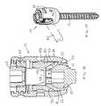
- FIGS. 1A and 1Bare simplified pictorial and sectional illustrations, respectively, of a connector assembly for a bone anchoring element, constructed and operative in accordance with an embodiment of the present invention
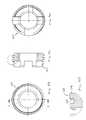
- FIGS. 2A , 2 B, 2 C and 2 Dare simplified pictorial, top view, sectional and side-view illustrations, respectively, of a double collet of the connector assembly of FIGS. 1A-1B , constructed and operative in accordance with an embodiment of the present invention
- FIGS. 3A , 3 B, 3 C and 3 Dare simplified front view, side view, sectional and thread detail view illustrations, respectively, of an outer closure element of the connector assembly of FIGS. 1A-1B , constructed and operative in accordance with an embodiment of the present invention
- FIGS. 4A , 4 B 4 C and 4 Dare simplified pictorial, top-view, side sectional and front sectional illustrations, respectively, of an interface ring of the connector assembly of FIGS. 1A-1B , constructed and operative in accordance with another embodiment of the present invention.
- FIGS. 5A , 5 B, 5 C and 5 Dare simplified pictorial, top view, sectional and thread detail view illustrations, respectively, of a cap element of the connector assembly of FIGS. 1A-1B , constructed and operative in accordance with an embodiment of the present invention.
- FIGS. 1A-1Billustrate a connector assembly 10 for a bone anchoring element 12 , constructed and operative in accordance with an embodiment of the present invention.
- the bone anchoring element 12includes a threaded mechanical fastener (for example, without limitation, a pedicle screw, a pedicle anchor device, a blocking screw for a pedicle anchoring device or any other device for attachment to the pedicle, vertebral body or any other bone) having a spherical proximal portion 14 (also referred to as a spherical head 14 ) and a (pointed) distal portion 16 .
- bone anchoring element 12can be a hook or other mechanical fastener with a spherical head.
- the spherical head 14may be formed with a socket for an Allen wrench or the like.
- the connector assembly 10includes a double collet 18 that includes an inner clamping portion 20 , formed by inner surfaces of a plurality of resilient fingers 22 (also referred to as tabs, leaves or petals, these terms and the like being used interchangeably) spaced around a longitudinal axis 24 thereof.
- Resilient fingers 22are separated from each other and are formed by cuts or grooves 26 formed in double collet 18 .
- the plurality of resilient fingers 22 of double collet 18define two wedge surfaces 30 (first or upper wedge surface 30 in the sense of the drawing) and 32 (second or lower wedge surface 32 ).
- the wedge surfacesare angled with respect to each other and are preferably conical in shape.
- Clamping portion 20resiliently clamps on spherical head 14 of bone anchoring element 12 .
- the connector assembly 10may include an outer closure element 34 that includes an inner clamping portion 36 ( FIG. 3C ).
- the inner clamping portion 36is preferably conical in shape, and corresponds to the outer conical contour of second wedge surface 32 of double collet 18 .
- Outer closure element 34may include a pair of arms 38 that define a channel 40 ( FIGS. 3A and 3C ), shaped to receive therein a connector element 42 ( FIGS. 1A-1B ).
- Channel 40is preferably U-shaped, but other shapes are possible.
- An upper portion 44 ( FIG. 3C ) of arms 38may be threaded.
- a pair of diametrically-opposed blind holes 46may be formed on the outside of arms 38 so as to create inner dimples 39 . Holes 46 may also be used for grasping outer closure element 34 with a grasping tool.
- the connector assembly 10may include an interface ring 48 .
- Interface ring 48may include a round base 50 with a hole 52 axially bored therethrough.
- Base 50is formed with an inner wedge surface 53 , formed such as by countersinking a conical surface.
- a pair of wing extensions 54extend (upward in the sense of FIG. 4A ) from base 50 .
- the wing extensions 54have inner sloping surfaces 56 .
- a generally flat upper portion 58 of base 50separates the wing extensions 54 from one another.
- Interface ring 48may also be formed with a pair of diametrically-opposed flat indentations 59 .
- the connector assembly 10may be constructed of any suitable, medically safe material, such as but not limited to, stainless steel alloy (e.g., AISI 316L), titanium or titanium alloy or chrome cobalt alloy, PEEK (polyetheretherketone), shape memory alloys or polymers, including resorbable materials, or any combination of the above. Any material may be coated, such as with HA (hydroxyapatite), any factors or substances including active or passive antibiotics, etc. Different parts of connector assembly 10 may be constructed of different materials with different resilience or hardness, or of the same material but treated to have different resilience or hardness.
- the connector element 42is illustrated as a rod with a cylindrical cross section.
- connector element 40may be any slender elongate element, such as but not limited to, a bar of hexagonal, rectangular or square cross section, a rod of elliptical cross section, and many others.
- FIG. 1BAfter bone anchoring element 12 (e.g., pedicle screw) is in place, the user places the inner clamping portion 20 of double collet 18 over spherical head 14 of bone anchoring element 12 .
- Interface ring 48is then placed over double collet 18 so that the inner wedge surface 53 sits against the first (upper) wedge surface 30 of resilient fingers 22 .
- the outer closure element 34is then placed over interface ring 48 and double collet 18 .
- the inner clamping portion 36 of outer closure element 34abuts against the second (lower) wedge surface 32 of resilient fingers 22 .
- the hexagonal socket of spherical head 14is still accessible for tightening with a wrench or other tool, because all the parts of the connector assembly have through holes for accessing spherical head 14 .
- the connector element 42is then placed in U-shaped channel 40 of outer closure element 34 . It is noted that connector element 42 also passes through the gap between arms 54 of interface ring 48 . It is further noted that the upper portion 58 of base 50 is slightly higher than the bottom of U-shaped channel 40 so that connector element 42 abuts against base 50 of interface ring 48 and not against outer closure element 34 . A threaded cap member 60 is then screwed on the upper portion 44 of arms 38 of outer closure element 34 . Cap member 60 is tightened against connector element 42 . This forces connector element 40 against the upper portion 58 of base 50 of interface ring 48 , which slides on and presses downwards (in the sense of the drawing) against the first wedge surface 30 of resilient fingers 22 of double collet 18 .
- This downward forcehas two wedging actions. First, the downward force causes the second wedge surface 32 to be wedged between outer closure element 34 and spherical head 14 . This squeezes and clamps the lower portion of resilient fingers 22 (second wedge surface 32 ) onto spherical head 14 of bone anchoring element 12 . Second, the downward force presses the upper portion of resilient fingers 22 (first wedge surface 30 ) onto the top of spherical head 14 of bone anchoring element 12 . The double clamping action makes the double collet 18 firmly grip spherical head 14 of bone anchoring element 12 . There is no contact between connector element 42 and spherical head 14 of bone anchoring element 12 .
- An auxiliary cap element 62may be threadedly received in inner threads of cap member 60 .
- the auxiliary cap element 62may be used to further clamp down on connector element 42 and provide a fine adjustment of the force thereupon.
- cap element 60may be formed with a thread 64 that comprises one flat side 66 and an opposite side 68 which is not parallel to flat side 66 but is angled about 10° thereto.
- This specially formed thread 64when tightened in complimentary female threads formed in upper portion 44 ( FIG. 3C ) of arms 38 of outer closure element 34 , tends to pull arms 38 inwards. This prevents cap element 60 from tending to force the arms 38 outwards, which would play against the desired tightening force on connector element 42 .
- the connector assemblies of the inventionpermit rotational adjustments with respect to the spherical head of the bone anchoring element and translational adjustments of the connector element before locking the connector element in place.
Landscapes
- Health & Medical Sciences (AREA)
- Orthopedic Medicine & Surgery (AREA)
- Life Sciences & Earth Sciences (AREA)
- Neurology (AREA)
- Surgery (AREA)
- Heart & Thoracic Surgery (AREA)
- Engineering & Computer Science (AREA)
- Biomedical Technology (AREA)
- Nuclear Medicine, Radiotherapy & Molecular Imaging (AREA)
- Medical Informatics (AREA)
- Molecular Biology (AREA)
- Animal Behavior & Ethology (AREA)
- General Health & Medical Sciences (AREA)
- Public Health (AREA)
- Veterinary Medicine (AREA)
- Surgical Instruments (AREA)
Abstract
Description
Claims (2)
Priority Applications (4)
| Application Number | Priority Date | Filing Date | Title |
|---|---|---|---|
| US11/949,916US7789900B2 (en) | 2007-12-04 | 2007-12-04 | Double collet connector assembly for bone anchoring element |
| EP08857440AEP2224869B1 (en) | 2007-12-04 | 2008-12-04 | Double collet connector assembly for bone anchoring element |
| AT08857440TATE524123T1 (en) | 2007-12-04 | 2008-12-04 | CONNECTION ARRANGEMENT WITH DOUBLE RECEPTACLE FOR A BONE ANCHORING ELEMENT |
| PCT/IL2008/001576WO2009072125A1 (en) | 2007-12-04 | 2008-12-04 | Double collet connector assembly for bone anchoring element |
Applications Claiming Priority (1)
| Application Number | Priority Date | Filing Date | Title |
|---|---|---|---|
| US11/949,916US7789900B2 (en) | 2007-12-04 | 2007-12-04 | Double collet connector assembly for bone anchoring element |
Publications (2)
| Publication Number | Publication Date |
|---|---|
| US20090143827A1 US20090143827A1 (en) | 2009-06-04 |
| US7789900B2true US7789900B2 (en) | 2010-09-07 |
Family
ID=40511026
Family Applications (1)
| Application Number | Title | Priority Date | Filing Date |
|---|---|---|---|
| US11/949,916Expired - Fee RelatedUS7789900B2 (en) | 2007-12-04 | 2007-12-04 | Double collet connector assembly for bone anchoring element |
Country Status (4)
| Country | Link |
|---|---|
| US (1) | US7789900B2 (en) |
| EP (1) | EP2224869B1 (en) |
| AT (1) | ATE524123T1 (en) |
| WO (1) | WO2009072125A1 (en) |
Cited By (77)
| Publication number | Priority date | Publication date | Assignee | Title |
|---|---|---|---|---|
| US20090163962A1 (en)* | 2007-12-20 | 2009-06-25 | Aesculap Implant Systems, Inc. | Locking device introducer instrument |
| US20090182384A1 (en)* | 2008-01-14 | 2009-07-16 | Warsaw Orthopedic, Inc. | Material combinations for medical device implants |
| US20100160978A1 (en)* | 2008-12-23 | 2010-06-24 | John Carbone | Bone screw assembly with non-uniform material |
| US8377067B2 (en) | 2004-02-27 | 2013-02-19 | Roger P. Jackson | Orthopedic implant rod reduction tool set and method |
| US8394133B2 (en) | 2004-02-27 | 2013-03-12 | Roger P. Jackson | Dynamic fixation assemblies with inner core and outer coil-like member |
| US8444681B2 (en) | 2009-06-15 | 2013-05-21 | Roger P. Jackson | Polyaxial bone anchor with pop-on shank, friction fit retainer and winged insert |
| US20130150852A1 (en)* | 2010-08-30 | 2013-06-13 | Zimmer Spine, Inc. | Polyaxial pedicle screw |
| US8790374B2 (en) | 2004-04-08 | 2014-07-29 | Globus Medical, Inc. | Polyaxial screw |
| US8814911B2 (en) | 2003-06-18 | 2014-08-26 | Roger P. Jackson | Polyaxial bone screw with cam connection and lock and release insert |
| US8888827B2 (en) | 2011-07-15 | 2014-11-18 | Globus Medical, Inc. | Orthopedic fixation devices and methods of installation thereof |
| US8894657B2 (en) | 2004-02-27 | 2014-11-25 | Roger P. Jackson | Tool system for dynamic spinal implants |
| US8911479B2 (en) | 2012-01-10 | 2014-12-16 | Roger P. Jackson | Multi-start closures for open implants |
| US8992579B1 (en) | 2011-03-08 | 2015-03-31 | Nuvasive, Inc. | Lateral fixation constructs and related methods |
| US8998959B2 (en) | 2009-06-15 | 2015-04-07 | Roger P Jackson | Polyaxial bone anchors with pop-on shank, fully constrained friction fit retainer and lock and release insert |
| US9050139B2 (en) | 2004-02-27 | 2015-06-09 | Roger P. Jackson | Orthopedic implant rod reduction tool set and method |
| US9060815B1 (en) | 2012-03-08 | 2015-06-23 | Nuvasive, Inc. | Systems and methods for performing spine surgery |
| US20150182260A1 (en)* | 2009-06-15 | 2015-07-02 | Roger P Jackson | Polyaxial bone anchors with pop-on shank, fully constrained friction fit retainer and lock and release insert |
| US9101426B2 (en) | 2012-10-11 | 2015-08-11 | Stryker Trauma Sa | Cable plug |
| US9168069B2 (en) | 2009-06-15 | 2015-10-27 | Roger P. Jackson | Polyaxial bone anchor with pop-on shank and winged insert with lower skirt for engaging a friction fit retainer |
| US9186484B2 (en) | 2010-07-01 | 2015-11-17 | DePuy Synthes Products, Inc. | Guidewire insertion methods and devices |
| US9186187B2 (en) | 2011-07-15 | 2015-11-17 | Globus Medical, Inc. | Orthopedic fixation devices and methods of installation thereof |
| US9198694B2 (en) | 2011-07-15 | 2015-12-01 | Globus Medical, Inc. | Orthopedic fixation devices and methods of installation thereof |
| US9216039B2 (en) | 2004-02-27 | 2015-12-22 | Roger P. Jackson | Dynamic spinal stabilization assemblies, tool set and method |
| US9259247B2 (en) | 2013-03-14 | 2016-02-16 | Medos International Sarl | Locking compression members for use with bone anchor assemblies and methods |
| US9259254B2 (en) | 2004-04-08 | 2016-02-16 | Globus Medical, Inc. | Polyaxial screw |
| US9289249B2 (en) | 2013-03-14 | 2016-03-22 | DePuy Synthes Products, Inc. | Bone anchors and surgical instruments with integrated guide tips |
| DE102014222890A1 (en)* | 2014-11-10 | 2016-05-12 | Premiere Medical Gmbh | Pedicle screw and pedicle screw system |
| US9358047B2 (en) | 2011-07-15 | 2016-06-07 | Globus Medical, Inc. | Orthopedic fixation devices and methods of installation thereof |
| US9393047B2 (en) | 2009-06-15 | 2016-07-19 | Roger P. Jackson | Polyaxial bone anchor with pop-on shank and friction fit retainer with low profile edge lock |
| US9427260B2 (en) | 2012-03-01 | 2016-08-30 | Globus Medical, Inc. | Closed-head polyaxial and monaxial screws |
| US9451992B2 (en)* | 2010-12-01 | 2016-09-27 | Facet-Link Inc. | Variable angle bone screw fixation arrangement |
| US9480517B2 (en) | 2009-06-15 | 2016-11-01 | Roger P. Jackson | Polyaxial bone anchor with pop-on shank, shank, friction fit retainer, winged insert and low profile edge lock |
| US9498254B2 (en) | 2013-03-14 | 2016-11-22 | Medos International Sarl | Bottom-loading bone anchor assemblies |
| US9517089B1 (en) | 2013-10-08 | 2016-12-13 | Nuvasive, Inc. | Bone anchor with offset rod connector |
| US9629669B2 (en) | 2004-11-23 | 2017-04-25 | Roger P. Jackson | Spinal fixation tool set and method |
| US9655655B2 (en) | 2011-08-16 | 2017-05-23 | Aesculap Implant Systems, Llc | Two step locking screw assembly |
| US9713488B2 (en) | 2008-02-04 | 2017-07-25 | Medos International Sarl | Methods for correction of spinal deformities |
| US9724145B2 (en) | 2013-03-14 | 2017-08-08 | Medos International Sarl | Bone anchor assemblies with multiple component bottom loading bone anchors |
| US9743957B2 (en) | 2004-11-10 | 2017-08-29 | Roger P. Jackson | Polyaxial bone screw with shank articulation pressure insert and method |
| US9775660B2 (en) | 2013-03-14 | 2017-10-03 | DePuy Synthes Products, Inc. | Bottom-loading bone anchor assemblies and methods |
| US9782204B2 (en) | 2012-09-28 | 2017-10-10 | Medos International Sarl | Bone anchor assemblies |
| US9907574B2 (en) | 2008-08-01 | 2018-03-06 | Roger P. Jackson | Polyaxial bone anchors with pop-on shank, friction fit fully restrained retainer, insert and tool receiving features |
| US9918747B2 (en) | 2013-03-14 | 2018-03-20 | DePuy Synthes Products, Inc. | Bone anchor assemblies and methods with improved locking |
| US9980753B2 (en) | 2009-06-15 | 2018-05-29 | Roger P Jackson | pivotal anchor with snap-in-place insert having rotation blocking extensions |
| US9993269B2 (en) | 2011-07-15 | 2018-06-12 | Globus Medical, Inc. | Orthopedic fixation devices and methods of installation thereof |
| US10039577B2 (en) | 2004-11-23 | 2018-08-07 | Roger P Jackson | Bone anchor receiver with horizontal radiused tool attachment structures and parallel planar outer surfaces |
| US10039578B2 (en) | 2003-12-16 | 2018-08-07 | DePuy Synthes Products, Inc. | Methods and devices for minimally invasive spinal fixation element placement |
| US10194951B2 (en) | 2005-05-10 | 2019-02-05 | Roger P. Jackson | Polyaxial bone anchor with compound articulation and pop-on shank |
| US10271880B2 (en) | 2012-12-05 | 2019-04-30 | Beth Israel Deaconess Medical Center, Inc. | Systems and methods for anisotropy restoring femoroplasty |
| US10299839B2 (en) | 2003-12-16 | 2019-05-28 | Medos International Sárl | Percutaneous access devices and bone anchor assemblies |
| US10342582B2 (en) | 2013-03-14 | 2019-07-09 | DePuy Synthes Products, Inc. | Bone anchor assemblies and methods with improved locking |
| US10363070B2 (en) | 2009-06-15 | 2019-07-30 | Roger P. Jackson | Pivotal bone anchor assemblies with pressure inserts and snap on articulating retainers |
| US10499968B2 (en) | 2014-08-08 | 2019-12-10 | Stryker European Holdings I, Llc | Cable plugs for bone plates |
| US11234738B2 (en) | 2018-11-16 | 2022-02-01 | Roger P. Jackson | Pivotal bone anchor assembly having a deployable collet insert with internal pressure ring |
| US20220168018A1 (en)* | 2007-01-26 | 2022-06-02 | Roger P. Jackson | Dynamic stabilization member |
| US11419642B2 (en) | 2003-12-16 | 2022-08-23 | Medos International Sarl | Percutaneous access devices and bone anchor assemblies |
| US20230044896A1 (en)* | 2020-01-17 | 2023-02-09 | Axess Vision Technology | Removable attachment system on a mast for a non-implantable medical device |
| US11751918B2 (en)* | 2020-03-12 | 2023-09-12 | Biedermann Technologies Gmbh & Co. Kg | Coupling device for use with a bone anchoring element and bone anchoring device with such a coupling device |
| US11751915B2 (en) | 2021-07-09 | 2023-09-12 | Roger P. Jackson | Modular spinal fixation system with bottom-loaded universal shank heads |
| US20230301689A1 (en)* | 2022-03-25 | 2023-09-28 | Globus Medical, Inc. | Stabilizing bones using screws and rods |
| US11793553B2 (en) | 2014-10-21 | 2023-10-24 | Roger P. Jackson | Pivotal bone anchor assembly having first and second split rings and an insert with post-placement tool deployment |
| US11925392B2 (en) | 2007-05-23 | 2024-03-12 | Roger P. Jackson | Pivotal bone anchor assembly with bottom loaded spherical shank head having a planar upper surface |
| US12042185B2 (en) | 2010-05-14 | 2024-07-23 | Roger P. Jackson | Pivotal bone anchor assembly with resiliently biased friction fit insert |
| US12053209B2 (en) | 2022-01-18 | 2024-08-06 | Roger P. Jackson | Spinal fixation systems with modular receiver and ring retainer sub-assemblies for connecting with universal shank heads |
| US12053217B2 (en) | 2019-12-17 | 2024-08-06 | Roger P. Jackson | Receiver assembly with rotation blocking side pockets for twist-in-place insert and method of assembly |
| US12070249B2 (en) | 2014-06-04 | 2024-08-27 | Jackson Roger P | Pivotal bone anchor assembly with bottom loaded shank head engaging retainer and closure engaging insert |
| US12082853B2 (en) | 2014-10-21 | 2024-09-10 | Roger P. Jackson | Pivotal bone anchor assembly with positioner-retainer containment and insert tool deployment |
| US12082850B2 (en) | 2007-09-17 | 2024-09-10 | Roger P. Jackson | Pivotal bone anchor assembly having twist-in-place insert and receiver with pre-formed axial rotation insert stops |
| US12102357B2 (en) | 2005-02-22 | 2024-10-01 | Roger P. Jackson | Pivotal bone anchor assembly with cannulated shank having a planar top surface and method of assembly |
| US12127766B2 (en) | 2021-03-05 | 2024-10-29 | Medos International Sàrl | Selectively locking polyaxial screw |
| US12137945B2 (en) | 2018-09-13 | 2024-11-12 | Roger P. Jackson | Pivotal bone anchor system with modular receiver sub-assemblies and universal bone anchors |
| US12262920B2 (en) | 2004-11-23 | 2025-04-01 | Roger P. Jackson | Method of assembling a bottom-loaded pivotal bone anchor assembly with compression insert and two-part shank retainer |
| US12310631B2 (en) | 2021-03-05 | 2025-05-27 | Medos International Sárl | Multi-feature polyaxial screw |
| US12357348B2 (en) | 2005-09-30 | 2025-07-15 | Roger P. Jackson | Method of assembling a pivotal bone anchor assembly with press-in-place insert |
| US12376894B2 (en) | 2005-07-14 | 2025-08-05 | Roger P. Jackson | Pivotal bone anchor assembly with ring retainer and twist-in-place pressure insert |
| US12414801B2 (en) | 2022-11-03 | 2025-09-16 | Roger P. Jackson | Spinal fixation system with modular receiver sub-assemblies for connecting with bi-spherical universal shank heads |
| US12440245B2 (en) | 2023-09-06 | 2025-10-14 | Pivotable bone anchor assembly with independent provisional locking by insert compressing member |
Families Citing this family (49)
| Publication number | Priority date | Publication date | Assignee | Title |
|---|---|---|---|---|
| US7833250B2 (en) | 2004-11-10 | 2010-11-16 | Jackson Roger P | Polyaxial bone screw with helically wound capture connection |
| WO2006052796A2 (en) | 2004-11-10 | 2006-05-18 | Jackson Roger P | Helical guide and advancement flange with break-off extensions |
| US8876868B2 (en) | 2002-09-06 | 2014-11-04 | Roger P. Jackson | Helical guide and advancement flange with radially loaded lip |
| US7377923B2 (en) | 2003-05-22 | 2008-05-27 | Alphatec Spine, Inc. | Variable angle spinal screw assembly |
| US8926670B2 (en) | 2003-06-18 | 2015-01-06 | Roger P. Jackson | Polyaxial bone screw assembly |
| US8377102B2 (en) | 2003-06-18 | 2013-02-19 | Roger P. Jackson | Polyaxial bone anchor with spline capture connection and lower pressure insert |
| US8398682B2 (en) | 2003-06-18 | 2013-03-19 | Roger P. Jackson | Polyaxial bone screw assembly |
| US8137386B2 (en) | 2003-08-28 | 2012-03-20 | Jackson Roger P | Polyaxial bone screw apparatus |
| US11241261B2 (en) | 2005-09-30 | 2022-02-08 | Roger P Jackson | Apparatus and method for soft spinal stabilization using a tensionable cord and releasable end structure |
| US8926672B2 (en) | 2004-11-10 | 2015-01-06 | Roger P. Jackson | Splay control closure for open bone anchor |
| WO2006057837A1 (en) | 2004-11-23 | 2006-06-01 | Jackson Roger P | Spinal fixation tool attachment structure |
| US8308782B2 (en) | 2004-11-23 | 2012-11-13 | Jackson Roger P | Bone anchors with longitudinal connecting member engaging inserts and closures for fixation and optional angulation |
| US10076361B2 (en) | 2005-02-22 | 2018-09-18 | Roger P. Jackson | Polyaxial bone screw with spherical capture, compression and alignment and retention structures |
| ES2348814T3 (en) | 2007-07-31 | 2010-12-15 | Biedermann Motech Gmbh | ANCHORAGE DEVICE Ã “SEO. |
| CA2781407A1 (en) | 2008-01-14 | 2009-07-23 | Michael P. Brenzel | Apparatus and methods for fracture repair |
| EP2265202B1 (en)* | 2008-04-22 | 2012-08-29 | Synthes GmbH | Bone fixation element with reduction tabs |
| US8057146B2 (en)* | 2008-08-01 | 2011-11-15 | Varian Semiconductor Equipment Associates, Inc. | Fastening apparatus |
| ES2375879T3 (en)* | 2008-12-23 | 2012-03-07 | Biedermann Motech Gmbh | RECEPTION AREA OF A ROD FOR COUPLING THE ROD IN AN BONE ANCHORAGE ELEMENT AND BONE ANCHORAGE DEVICE WITH SUCH RECEPTION AREA. |
| ES2423676T3 (en) | 2008-12-29 | 2013-09-23 | Biedermann Technologies Gmbh & Co. Kg | Housing piece to accommodate a rod in order to couple the rod to a bone anchoring element, and bone anchoring device with such a housing piece |
| ES2378588T3 (en) | 2008-12-30 | 2012-04-16 | Biedermann Motech Gmbh | Receiving part for receiving a rod for coupling the rod in a bone anchoring element and bone anchoring device with such receiving part |
| US9668771B2 (en) | 2009-06-15 | 2017-06-06 | Roger P Jackson | Soft stabilization assemblies with off-set connector |
| TWI369971B (en)* | 2009-07-03 | 2012-08-11 | Accumis Inc | Spine fixation device |
| EP2485654B1 (en) | 2009-10-05 | 2021-05-05 | Jackson P. Roger | Polyaxial bone anchor with non-pivotable retainer and pop-on shank, some with friction fit |
| US20120041490A1 (en)* | 2009-11-18 | 2012-02-16 | Synthes Usa, Llc | Variable offset spine fixation system and method |
| US20110178520A1 (en) | 2010-01-15 | 2011-07-21 | Kyle Taylor | Rotary-rigid orthopaedic rod |
| WO2011091052A1 (en) | 2010-01-20 | 2011-07-28 | Kyle Taylor | Apparatus and methods for bone access and cavity preparation |
| WO2011112615A1 (en) | 2010-03-08 | 2011-09-15 | Krinke Todd A | Apparatus and methods for securing a bone implant |
| US8617216B2 (en) | 2010-04-05 | 2013-12-31 | David L. Brumfield | Fully-adjustable bone fixation device |
| US9084634B1 (en)* | 2010-07-09 | 2015-07-21 | Theken Spine, Llc | Uniplanar screw |
| US10603083B1 (en) | 2010-07-09 | 2020-03-31 | Theken Spine, Llc | Apparatus and method for limiting a range of angular positions of a screw |
| US10111694B2 (en)* | 2010-10-05 | 2018-10-30 | Skeletal Design Partnership, Llc | Pedicle screw assembly and method of assembly |
| CN102133132B (en)* | 2010-12-31 | 2013-01-02 | 上海微创骨科医疗科技有限公司 | Dynamic screw implant for pedicle of vertebral arch |
| US11103286B2 (en) | 2011-07-15 | 2021-08-31 | Globus Medical, Inc. | Orthopedic fixation devices and methods of installation thereof |
| US9060818B2 (en)* | 2011-09-01 | 2015-06-23 | DePuy Synthes Products, Inc. | Bone implants |
| US20130110174A1 (en)* | 2011-10-31 | 2013-05-02 | Warsaw Orthopedic, Inc. | Methods for installing a vertebral construct |
| US8911478B2 (en) | 2012-11-21 | 2014-12-16 | Roger P. Jackson | Splay control closure for open bone anchor |
| ITVR20130006A1 (en)* | 2013-01-11 | 2014-07-12 | Tecres Spa | ADJUSTABLE SPHERICAL JOINT |
| US10058354B2 (en) | 2013-01-28 | 2018-08-28 | Roger P. Jackson | Pivotal bone anchor assembly with frictional shank head seating surfaces |
| US8852239B2 (en) | 2013-02-15 | 2014-10-07 | Roger P Jackson | Sagittal angle screw with integral shank and receiver |
| US20140257418A1 (en)* | 2013-03-07 | 2014-09-11 | Kyphon Sarl | Surgical tool holder |
| USD750258S1 (en)* | 2013-09-06 | 2016-02-23 | Asalus Medical Instruments Ltd | Medical instrument |
| US9566092B2 (en) | 2013-10-29 | 2017-02-14 | Roger P. Jackson | Cervical bone anchor with collet retainer and outer locking sleeve |
| US9717533B2 (en) | 2013-12-12 | 2017-08-01 | Roger P. Jackson | Bone anchor closure pivot-splay control flange form guide and advancement structure |
| CN105939677A (en) | 2013-12-12 | 2016-09-14 | 康文图斯整形外科公司 | Tissue displacement tools and methods |
| US9451993B2 (en) | 2014-01-09 | 2016-09-27 | Roger P. Jackson | Bi-radial pop-on cervical bone anchor |
| US9597119B2 (en) | 2014-06-04 | 2017-03-21 | Roger P. Jackson | Polyaxial bone anchor with polymer sleeve |
| WO2019010252A2 (en) | 2017-07-04 | 2019-01-10 | Conventus Orthopaedics, Inc. | APPARATUS AND METHODS FOR TREATING BONES |
| USD956233S1 (en)* | 2020-04-24 | 2022-06-28 | Solco Biomedical Co., Ltd. | Cervical screw |
| US11690652B1 (en)* | 2022-08-17 | 2023-07-04 | Zavation Medical Products Llc | Modular screw assembly |
Citations (6)
| Publication number | Priority date | Publication date | Assignee | Title |
|---|---|---|---|---|
| US5882350A (en) | 1995-04-13 | 1999-03-16 | Fastenetix, Llc | Polyaxial pedicle screw having a threaded and tapered compression locking mechanism |
| FR2796545A1 (en) | 1999-07-22 | 2001-01-26 | Dimso Sa | Polyaxial connector for spinal support frame has head, coupling and connector with deformable seating |
| WO2006116437A2 (en) | 2005-04-25 | 2006-11-02 | Synthes (U.S.A.) | Bone anchor with locking cap and method of spinal fixation |
| US20060276792A1 (en)* | 2005-05-25 | 2006-12-07 | Ensign Michael D | Low profile pedicle screw and rod assembly |
| US20070049933A1 (en) | 2005-08-30 | 2007-03-01 | Ahn Sae Y | Multi-axial spinal pedicle screw |
| US20070118123A1 (en)* | 2005-11-21 | 2007-05-24 | Strausbaugh William L | Polyaxial bone anchors with increased angulation |
- 2007
- 2007-12-04USUS11/949,916patent/US7789900B2/ennot_activeExpired - Fee Related
- 2008
- 2008-12-04ATAT08857440Tpatent/ATE524123T1/ennot_activeIP Right Cessation
- 2008-12-04EPEP08857440Apatent/EP2224869B1/ennot_activeNot-in-force
- 2008-12-04WOPCT/IL2008/001576patent/WO2009072125A1/enactiveApplication Filing
Patent Citations (6)
| Publication number | Priority date | Publication date | Assignee | Title |
|---|---|---|---|---|
| US5882350A (en) | 1995-04-13 | 1999-03-16 | Fastenetix, Llc | Polyaxial pedicle screw having a threaded and tapered compression locking mechanism |
| FR2796545A1 (en) | 1999-07-22 | 2001-01-26 | Dimso Sa | Polyaxial connector for spinal support frame has head, coupling and connector with deformable seating |
| WO2006116437A2 (en) | 2005-04-25 | 2006-11-02 | Synthes (U.S.A.) | Bone anchor with locking cap and method of spinal fixation |
| US20060276792A1 (en)* | 2005-05-25 | 2006-12-07 | Ensign Michael D | Low profile pedicle screw and rod assembly |
| US20070049933A1 (en) | 2005-08-30 | 2007-03-01 | Ahn Sae Y | Multi-axial spinal pedicle screw |
| US20070118123A1 (en)* | 2005-11-21 | 2007-05-24 | Strausbaugh William L | Polyaxial bone anchors with increased angulation |
Cited By (141)
| Publication number | Priority date | Publication date | Assignee | Title |
|---|---|---|---|---|
| US8814911B2 (en) | 2003-06-18 | 2014-08-26 | Roger P. Jackson | Polyaxial bone screw with cam connection and lock and release insert |
| US10299839B2 (en) | 2003-12-16 | 2019-05-28 | Medos International Sárl | Percutaneous access devices and bone anchor assemblies |
| US10039578B2 (en) | 2003-12-16 | 2018-08-07 | DePuy Synthes Products, Inc. | Methods and devices for minimally invasive spinal fixation element placement |
| US11426216B2 (en) | 2003-12-16 | 2022-08-30 | DePuy Synthes Products, Inc. | Methods and devices for minimally invasive spinal fixation element placement |
| US11419642B2 (en) | 2003-12-16 | 2022-08-23 | Medos International Sarl | Percutaneous access devices and bone anchor assemblies |
| US9055978B2 (en) | 2004-02-27 | 2015-06-16 | Roger P. Jackson | Orthopedic implant rod reduction tool set and method |
| US8894657B2 (en) | 2004-02-27 | 2014-11-25 | Roger P. Jackson | Tool system for dynamic spinal implants |
| US9918751B2 (en) | 2004-02-27 | 2018-03-20 | Roger P. Jackson | Tool system for dynamic spinal implants |
| US9216039B2 (en) | 2004-02-27 | 2015-12-22 | Roger P. Jackson | Dynamic spinal stabilization assemblies, tool set and method |
| US8394133B2 (en) | 2004-02-27 | 2013-03-12 | Roger P. Jackson | Dynamic fixation assemblies with inner core and outer coil-like member |
| US9050139B2 (en) | 2004-02-27 | 2015-06-09 | Roger P. Jackson | Orthopedic implant rod reduction tool set and method |
| US8377067B2 (en) | 2004-02-27 | 2013-02-19 | Roger P. Jackson | Orthopedic implant rod reduction tool set and method |
| US9259254B2 (en) | 2004-04-08 | 2016-02-16 | Globus Medical, Inc. | Polyaxial screw |
| US9179937B2 (en) | 2004-04-08 | 2015-11-10 | Globus Medical, Inc. | Polyaxial screw |
| US8894691B2 (en) | 2004-04-08 | 2014-11-25 | Globus Medical, Inc. | Polyaxial screw |
| US8790374B2 (en) | 2004-04-08 | 2014-07-29 | Globus Medical, Inc. | Polyaxial screw |
| US9743957B2 (en) | 2004-11-10 | 2017-08-29 | Roger P. Jackson | Polyaxial bone screw with shank articulation pressure insert and method |
| US10039577B2 (en) | 2004-11-23 | 2018-08-07 | Roger P Jackson | Bone anchor receiver with horizontal radiused tool attachment structures and parallel planar outer surfaces |
| US9629669B2 (en) | 2004-11-23 | 2017-04-25 | Roger P. Jackson | Spinal fixation tool set and method |
| US11389214B2 (en) | 2004-11-23 | 2022-07-19 | Roger P. Jackson | Spinal fixation tool set and method |
| US12262920B2 (en) | 2004-11-23 | 2025-04-01 | Roger P. Jackson | Method of assembling a bottom-loaded pivotal bone anchor assembly with compression insert and two-part shank retainer |
| US12102357B2 (en) | 2005-02-22 | 2024-10-01 | Roger P. Jackson | Pivotal bone anchor assembly with cannulated shank having a planar top surface and method of assembly |
| US10194951B2 (en) | 2005-05-10 | 2019-02-05 | Roger P. Jackson | Polyaxial bone anchor with compound articulation and pop-on shank |
| US12185984B2 (en) | 2005-05-27 | 2025-01-07 | Roger P. Jackson | Method of assembling a pivotal bone anchor screw with insert tool deployment |
| US12376894B2 (en) | 2005-07-14 | 2025-08-05 | Roger P. Jackson | Pivotal bone anchor assembly with ring retainer and twist-in-place pressure insert |
| US11957386B2 (en) | 2005-09-30 | 2024-04-16 | Roger P. Jackson | Pivotal bone anchor assembly having a downwardly-displaceable snap-in-place insert and method of assembly |
| US12357348B2 (en) | 2005-09-30 | 2025-07-15 | Roger P. Jackson | Method of assembling a pivotal bone anchor assembly with press-in-place insert |
| US10792074B2 (en) | 2007-01-22 | 2020-10-06 | Roger P. Jackson | Pivotal bone anchor assemly with twist-in-place friction fit insert |
| US20220168018A1 (en)* | 2007-01-26 | 2022-06-02 | Roger P. Jackson | Dynamic stabilization member |
| US11925392B2 (en) | 2007-05-23 | 2024-03-12 | Roger P. Jackson | Pivotal bone anchor assembly with bottom loaded spherical shank head having a planar upper surface |
| US12251139B2 (en) | 2007-05-23 | 2025-03-18 | Roger P. Jackson | Pivotal bone anchor screw with nested two-piece closure and independent locking twist-in-place insert |
| US12082850B2 (en) | 2007-09-17 | 2024-09-10 | Roger P. Jackson | Pivotal bone anchor assembly having twist-in-place insert and receiver with pre-formed axial rotation insert stops |
| US20090163962A1 (en)* | 2007-12-20 | 2009-06-25 | Aesculap Implant Systems, Inc. | Locking device introducer instrument |
| US8998958B2 (en)* | 2007-12-20 | 2015-04-07 | Aesculap Implant Systems, Llc | Locking device introducer instrument |
| KR20100112572A (en)* | 2008-01-14 | 2010-10-19 | 워쏘우 오르쏘페딕 인코포레이티드 | Material combinations for a pedicle screw assembly |
| US20090182384A1 (en)* | 2008-01-14 | 2009-07-16 | Warsaw Orthopedic, Inc. | Material combinations for medical device implants |
| US10201377B2 (en) | 2008-02-04 | 2019-02-12 | Medos International Sarl | Methods for correction of spinal deformities |
| US10987145B2 (en) | 2008-02-04 | 2021-04-27 | Medos International Sarl | Methods for correction of spinal deformities |
| US9713488B2 (en) | 2008-02-04 | 2017-07-25 | Medos International Sarl | Methods for correction of spinal deformities |
| US9907574B2 (en) | 2008-08-01 | 2018-03-06 | Roger P. Jackson | Polyaxial bone anchors with pop-on shank, friction fit fully restrained retainer, insert and tool receiving features |
| US12376886B2 (en) | 2008-08-01 | 2025-08-05 | Roger P. Jackson | Pivotal bone anchor assembly with retainer pre-positioned in expansion chamber and tool-deployable insert |
| US20100160978A1 (en)* | 2008-12-23 | 2010-06-24 | John Carbone | Bone screw assembly with non-uniform material |
| US20150182260A1 (en)* | 2009-06-15 | 2015-07-02 | Roger P Jackson | Polyaxial bone anchors with pop-on shank, fully constrained friction fit retainer and lock and release insert |
| US10363070B2 (en) | 2009-06-15 | 2019-07-30 | Roger P. Jackson | Pivotal bone anchor assemblies with pressure inserts and snap on articulating retainers |
| US12185983B2 (en) | 2009-06-15 | 2025-01-07 | Roger P. Jackson | Receiver assembly having a vertical tool-engaging slot for independent lock via tooling |
| US12207847B2 (en)* | 2009-06-15 | 2025-01-28 | Roger P. Jackson | Modular pivotal bone anchor assembly having pre-loaded insert engageable with restrained pre-loaded expandable retainer |
| US8444681B2 (en) | 2009-06-15 | 2013-05-21 | Roger P. Jackson | Polyaxial bone anchor with pop-on shank, friction fit retainer and winged insert |
| US12402917B2 (en) | 2009-06-15 | 2025-09-02 | Roger P. Jackson | Pivotal bone anchor assembly with independent provisional locking |
| US9504496B2 (en) | 2009-06-15 | 2016-11-29 | Roger P. Jackson | Polyaxial bone anchor with pop-on shank, friction fit retainer and winged insert |
| US8998959B2 (en) | 2009-06-15 | 2015-04-07 | Roger P Jackson | Polyaxial bone anchors with pop-on shank, fully constrained friction fit retainer and lock and release insert |
| US9480517B2 (en) | 2009-06-15 | 2016-11-01 | Roger P. Jackson | Polyaxial bone anchor with pop-on shank, shank, friction fit retainer, winged insert and low profile edge lock |
| US11559335B2 (en)* | 2009-06-15 | 2023-01-24 | Roger P Jackson | Pivotal bone anchor assembly with insert tool deployment |
| US12082854B2 (en) | 2009-06-15 | 2024-09-10 | Roger P. Jackson | Method of assembling a pivotable bone anchor assembly with a slidable retaining structure |
| US20160228153A9 (en)* | 2009-06-15 | 2016-08-11 | Roger P Jackson | Polyaxial bone anchors with pop-on shank, fully constrained friction fit retainer and lock and release insert |
| US20230270470A1 (en)* | 2009-06-15 | 2023-08-31 | Roger P. Jackson | Modular pivotal bone anchor assembly having pre-loaded insert engageable with restrained pre-loaded expandable retainer |
| US9393047B2 (en) | 2009-06-15 | 2016-07-19 | Roger P. Jackson | Polyaxial bone anchor with pop-on shank and friction fit retainer with low profile edge lock |
| US9918745B2 (en) | 2009-06-15 | 2018-03-20 | Roger P. Jackson | Polyaxial bone anchor with pop-on shank and winged insert with friction fit compressive collet |
| US11751916B2 (en) | 2009-06-15 | 2023-09-12 | Roger P. Jackson | Pivotal bone anchor assembly with polyaxial screw having frusto-conical upper surface |
| US11229457B2 (en)* | 2009-06-15 | 2022-01-25 | Roger P. Jackson | Pivotal bone anchor assembly with insert tool deployment |
| US9980753B2 (en) | 2009-06-15 | 2018-05-29 | Roger P Jackson | pivotal anchor with snap-in-place insert having rotation blocking extensions |
| US9168069B2 (en) | 2009-06-15 | 2015-10-27 | Roger P. Jackson | Polyaxial bone anchor with pop-on shank and winged insert with lower skirt for engaging a friction fit retainer |
| US11998247B2 (en) | 2009-06-15 | 2024-06-04 | Roger P. Jackson | Method of assembling a pivotal bone anchor assembly using insert tool deployment |
| US12329422B2 (en) | 2010-05-14 | 2025-06-17 | Roger P. Jackson | Pivotal bone anchor assembly with resiliently axially compressible shank head and rod engaging insert |
| US12383311B2 (en) | 2010-05-14 | 2025-08-12 | Roger P. Jackson | Pivotal bone anchor assembly and method for use thereof |
| US12042185B2 (en) | 2010-05-14 | 2024-07-23 | Roger P. Jackson | Pivotal bone anchor assembly with resiliently biased friction fit insert |
| US9186484B2 (en) | 2010-07-01 | 2015-11-17 | DePuy Synthes Products, Inc. | Guidewire insertion methods and devices |
| US12082851B2 (en) | 2010-08-30 | 2024-09-10 | Zimmer Spine, Inc. | Polyaxial pedicle screw |
| US11166751B2 (en) | 2010-08-30 | 2021-11-09 | Zimmer Spine, Inc. | Polyaxial pedicle screw |
| US9636148B2 (en) | 2010-08-30 | 2017-05-02 | Zimmer Spine, Inc. | Polyaxial pedicle screw |
| US10182844B2 (en) | 2010-08-30 | 2019-01-22 | Zimmer Spine, Inc. | Polyaxial pedicle screw |
| US20130150852A1 (en)* | 2010-08-30 | 2013-06-13 | Zimmer Spine, Inc. | Polyaxial pedicle screw |
| US9198695B2 (en)* | 2010-08-30 | 2015-12-01 | Zimmer Spine, Inc. | Polyaxial pedicle screw |
| US10945766B2 (en) | 2010-08-30 | 2021-03-16 | Zimmer Spine, Inc. | Polyaxial pedicle screw |
| US10925646B2 (en) | 2010-08-30 | 2021-02-23 | Zimmer Spine, Inc. | Polyaxial pedicle screw |
| US9451992B2 (en)* | 2010-12-01 | 2016-09-27 | Facet-Link Inc. | Variable angle bone screw fixation arrangement |
| US8992579B1 (en) | 2011-03-08 | 2015-03-31 | Nuvasive, Inc. | Lateral fixation constructs and related methods |
| US9358047B2 (en) | 2011-07-15 | 2016-06-07 | Globus Medical, Inc. | Orthopedic fixation devices and methods of installation thereof |
| US8888827B2 (en) | 2011-07-15 | 2014-11-18 | Globus Medical, Inc. | Orthopedic fixation devices and methods of installation thereof |
| US12245795B2 (en) | 2011-07-15 | 2025-03-11 | Globus Medical, Inc. | Orthopedic fixation devices and methods of installation thereof |
| US9549763B2 (en) | 2011-07-15 | 2017-01-24 | Globus Medical, Inc. | Orthopedic fixation devices and methods of installation thereof |
| US9186187B2 (en) | 2011-07-15 | 2015-11-17 | Globus Medical, Inc. | Orthopedic fixation devices and methods of installation thereof |
| US9198694B2 (en) | 2011-07-15 | 2015-12-01 | Globus Medical, Inc. | Orthopedic fixation devices and methods of installation thereof |
| US11090087B2 (en) | 2011-07-15 | 2021-08-17 | Globus Medical, Inc. | Orthopedic fixation devices and methods of installation thereof |
| US9993269B2 (en) | 2011-07-15 | 2018-06-12 | Globus Medical, Inc. | Orthopedic fixation devices and methods of installation thereof |
| US9655655B2 (en) | 2011-08-16 | 2017-05-23 | Aesculap Implant Systems, Llc | Two step locking screw assembly |
| US11911075B2 (en) | 2012-01-10 | 2024-02-27 | Roger P. Jackson | Pivotal bone anchor assembly with increased shank angulation |
| US8911479B2 (en) | 2012-01-10 | 2014-12-16 | Roger P. Jackson | Multi-start closures for open implants |
| US10219839B2 (en) | 2012-03-01 | 2019-03-05 | Globus Medical, Inc. | Closed-head polyaxial and monaxial screws |
| US9427260B2 (en) | 2012-03-01 | 2016-08-30 | Globus Medical, Inc. | Closed-head polyaxial and monaxial screws |
| US11439439B2 (en) | 2012-03-01 | 2022-09-13 | Globus Medical, Inc. | Closed-head polyaxial and monaxial screws |
| US11890036B2 (en) | 2012-03-01 | 2024-02-06 | Globus Medical Inc. | Closed-head polyaxial and monaxial screws |
| US9060815B1 (en) | 2012-03-08 | 2015-06-23 | Nuvasive, Inc. | Systems and methods for performing spine surgery |
| US9579131B1 (en) | 2012-03-08 | 2017-02-28 | Nuvasive, Inc. | Systems and methods for performing spine surgery |
| US10786284B2 (en) | 2012-09-28 | 2020-09-29 | Medos International Sarl | Bone anchor assemblies |
| US9782204B2 (en) | 2012-09-28 | 2017-10-10 | Medos International Sarl | Bone anchor assemblies |
| US10226282B2 (en) | 2012-09-28 | 2019-03-12 | Medos International Sarl | Bone anchor assemblies |
| US9101426B2 (en) | 2012-10-11 | 2015-08-11 | Stryker Trauma Sa | Cable plug |
| US11737797B2 (en) | 2012-12-05 | 2023-08-29 | Beth Israel Deaconess Medical Center, Inc. | Systems and methods for anisotropy restoring femoroplasty |
| US10271880B2 (en) | 2012-12-05 | 2019-04-30 | Beth Israel Deaconess Medical Center, Inc. | Systems and methods for anisotropy restoring femoroplasty |
| US9724145B2 (en) | 2013-03-14 | 2017-08-08 | Medos International Sarl | Bone anchor assemblies with multiple component bottom loading bone anchors |
| US9724130B2 (en) | 2013-03-14 | 2017-08-08 | Medos International Sarl | Locking compression members for use with bone anchor assemblies and methods |
| US11311318B2 (en) | 2013-03-14 | 2022-04-26 | DePuy Synthes Products, Inc. | Bone anchor assemblies and methods with improved locking |
| US10987138B2 (en) | 2013-03-14 | 2021-04-27 | Medos International Sari | Locking compression members for use with bone anchor assemblies and methods |
| US9259247B2 (en) | 2013-03-14 | 2016-02-16 | Medos International Sarl | Locking compression members for use with bone anchor assemblies and methods |
| US9289249B2 (en) | 2013-03-14 | 2016-03-22 | DePuy Synthes Products, Inc. | Bone anchors and surgical instruments with integrated guide tips |
| US10342582B2 (en) | 2013-03-14 | 2019-07-09 | DePuy Synthes Products, Inc. | Bone anchor assemblies and methods with improved locking |
| US10238441B2 (en) | 2013-03-14 | 2019-03-26 | Medos International Sàrl | Bottom-loading bone anchor assemblies and methods |
| US11937857B2 (en) | 2013-03-14 | 2024-03-26 | DePuy Synthes Products, Inc. | Bone anchors and surgical instruments with integrated guide tips |
| US10413339B2 (en) | 2013-03-14 | 2019-09-17 | DePuy Synthes Products, Inc. | Bone anchors and surgical instruments with integrated guide tips |
| US10413342B2 (en) | 2013-03-14 | 2019-09-17 | Medos International Sárl | Bone anchor assemblies with multiple component bottom loading bone anchors |
| US9918747B2 (en) | 2013-03-14 | 2018-03-20 | DePuy Synthes Products, Inc. | Bone anchor assemblies and methods with improved locking |
| US9433445B2 (en) | 2013-03-14 | 2016-09-06 | DePuy Synthes Products, Inc. | Bone anchors and surgical instruments with integrated guide tips |
| US9498254B2 (en) | 2013-03-14 | 2016-11-22 | Medos International Sarl | Bottom-loading bone anchor assemblies |
| US11457961B2 (en) | 2013-03-14 | 2022-10-04 | DePuy Synthes Products, Inc. | Bone anchors and surgical instruments with integrated guide tips |
| US10321938B2 (en) | 2013-03-14 | 2019-06-18 | Medos International Sàrl | Locking compression members for use with bone anchor assemblies and methods |
| US9775660B2 (en) | 2013-03-14 | 2017-10-03 | DePuy Synthes Products, Inc. | Bottom-loading bone anchor assemblies and methods |
| US12082852B2 (en) | 2013-03-14 | 2024-09-10 | Medos International Sàrl | Locking compression members for use with bone anchor assemblies and methods |
| US9517089B1 (en) | 2013-10-08 | 2016-12-13 | Nuvasive, Inc. | Bone anchor with offset rod connector |
| US12070249B2 (en) | 2014-06-04 | 2024-08-27 | Jackson Roger P | Pivotal bone anchor assembly with bottom loaded shank head engaging retainer and closure engaging insert |
| US10499968B2 (en) | 2014-08-08 | 2019-12-10 | Stryker European Holdings I, Llc | Cable plugs for bone plates |
| US11793553B2 (en) | 2014-10-21 | 2023-10-24 | Roger P. Jackson | Pivotal bone anchor assembly having first and second split rings and an insert with post-placement tool deployment |
| US12167872B2 (en) | 2014-10-21 | 2024-12-17 | Roger P. Jackson | Bottom loaded pivotal bone anchor assembly with locking and blocking rings and insert tool deployment |
| US12082853B2 (en) | 2014-10-21 | 2024-09-10 | Roger P. Jackson | Pivotal bone anchor assembly with positioner-retainer containment and insert tool deployment |
| US12251138B2 (en) | 2014-10-21 | 2025-03-18 | Roger P. Jackson | Pivotal bone anchor assembly with biasing members for pre-lock friction fit |
| DE102014222890A1 (en)* | 2014-11-10 | 2016-05-12 | Premiere Medical Gmbh | Pedicle screw and pedicle screw system |
| DE102014222890B4 (en)* | 2014-11-10 | 2018-02-15 | Premiere Medical Gmbh | Pedicle screw and pedicle screw system |
| US12137945B2 (en) | 2018-09-13 | 2024-11-12 | Roger P. Jackson | Pivotal bone anchor system with modular receiver sub-assemblies and universal bone anchors |
| US11234738B2 (en) | 2018-11-16 | 2022-02-01 | Roger P. Jackson | Pivotal bone anchor assembly having a deployable collet insert with internal pressure ring |
| US11497533B2 (en) | 2018-11-16 | 2022-11-15 | Roger P. Jackson | Pivotal bone anchor assembly having a deployable collet insert with internal pressure ring |
| US12053217B2 (en) | 2019-12-17 | 2024-08-06 | Roger P. Jackson | Receiver assembly with rotation blocking side pockets for twist-in-place insert and method of assembly |
| US20230044896A1 (en)* | 2020-01-17 | 2023-02-09 | Axess Vision Technology | Removable attachment system on a mast for a non-implantable medical device |
| US11751918B2 (en)* | 2020-03-12 | 2023-09-12 | Biedermann Technologies Gmbh & Co. Kg | Coupling device for use with a bone anchoring element and bone anchoring device with such a coupling device |
| US12310631B2 (en) | 2021-03-05 | 2025-05-27 | Medos International Sárl | Multi-feature polyaxial screw |
| US12127766B2 (en) | 2021-03-05 | 2024-10-29 | Medos International Sàrl | Selectively locking polyaxial screw |
| US12364515B2 (en) | 2021-03-05 | 2025-07-22 | Medos International Sàrl | Multi-feature polyaxial screw |
| US12096964B2 (en) | 2021-07-09 | 2024-09-24 | Roger P. Jackson | Modular bone anchor system with bottom loaded shank heads having a single shank head shape |
| US11751915B2 (en) | 2021-07-09 | 2023-09-12 | Roger P. Jackson | Modular spinal fixation system with bottom-loaded universal shank heads |
| US12053209B2 (en) | 2022-01-18 | 2024-08-06 | Roger P. Jackson | Spinal fixation systems with modular receiver and ring retainer sub-assemblies for connecting with universal shank heads |
| US20230301689A1 (en)* | 2022-03-25 | 2023-09-28 | Globus Medical, Inc. | Stabilizing bones using screws and rods |
| US12414801B2 (en) | 2022-11-03 | 2025-09-16 | Roger P. Jackson | Spinal fixation system with modular receiver sub-assemblies for connecting with bi-spherical universal shank heads |
| US12440245B2 (en) | 2023-09-06 | 2025-10-14 | Pivotable bone anchor assembly with independent provisional locking by insert compressing member |
Also Published As
| Publication number | Publication date |
|---|---|
| EP2224869B1 (en) | 2011-09-14 |
| WO2009072125A1 (en) | 2009-06-11 |
| US20090143827A1 (en) | 2009-06-04 |
| EP2224869A1 (en) | 2010-09-08 |
| ATE524123T1 (en) | 2011-09-15 |
Similar Documents
| Publication | Publication Date | Title |
|---|---|---|
| US7789900B2 (en) | Double collet connector assembly for bone anchoring element | |
| US20080269742A1 (en) | Connector assembly for bone anchoring element | |
| US9974570B2 (en) | Transverse connector | |
| EP0986338B1 (en) | Multi-axial bone screw assembly | |
| AU734406B2 (en) | Multi-axial bone screw assembly | |
| AU773530B2 (en) | Multi-axial bone screw assembly | |
| US8133262B2 (en) | Large diameter bone anchor assembly | |
| AU2006229952B2 (en) | Multi-axial connection system | |
| US8221473B2 (en) | Spinal rod connector assembly for a vertebral bone screw | |
| US20070123870A1 (en) | Bi-polar screw assembly | |
| US20100100137A1 (en) | Dynamic Anchor Assembly for Connecting Elements in Spinal Surgical Procedures | |
| US20100249846A1 (en) | Variable height, multi-axial bone screw assembly | |
| WO2007114834A1 (en) | Multi-axial, double locking bone screw assembly | |
| WO2007040553A1 (en) | Hybrid jointed bone screw system | |
| US8523915B2 (en) | Friction set screw for use with spinal implant systems | |
| AU2004281737A1 (en) | Polyaxial bone anchor and method of spinal fixation | |
| EP2563279A1 (en) | Engaging member with cavity-base for engaging a connecting element to a bone anchor | |
| US20160095639A1 (en) | Washer assembly for spinal fixation screw |
Legal Events
| Date | Code | Title | Description |
|---|---|---|---|
| AS | Assignment | Owner name:EXPANDING ORTHOPEDICS INC., ISRAEL Free format text:ASSIGNMENT OF ASSIGNORS INTEREST;ASSIGNORS:LEVY, MARK M;ZYLBERBERG, EYAL;SPANIER, YAIR;REEL/FRAME:020260/0155 Effective date:20071205 | |
| FEPP | Fee payment procedure | Free format text:PAYOR NUMBER ASSIGNED (ORIGINAL EVENT CODE: ASPN); ENTITY STATUS OF PATENT OWNER: SMALL ENTITY | |
| FPAY | Fee payment | Year of fee payment:4 | |
| SULP | Surcharge for late payment | ||
| FEPP | Fee payment procedure | Free format text:MAINTENANCE FEE REMINDER MAILED (ORIGINAL EVENT CODE: REM.) | |
| AS | Assignment | Owner name:TWIN BROOK CAPITAL PARTNERS, LLC, AS AGENT, ILLINOIS Free format text:SECURITY INTEREST;ASSIGNOR:CORELINK, LLC;REEL/FRAME:045951/0918 Effective date:20180530 Owner name:TWIN BROOK CAPITAL PARTNERS, LLC, AS AGENT, ILLINO Free format text:SECURITY INTEREST;ASSIGNOR:CORELINK, LLC;REEL/FRAME:045951/0918 Effective date:20180530 | |
| LAPS | Lapse for failure to pay maintenance fees | Free format text:PATENT EXPIRED FOR FAILURE TO PAY MAINTENANCE FEES (ORIGINAL EVENT CODE: EXP.); ENTITY STATUS OF PATENT OWNER: SMALL ENTITY | |
| STCH | Information on status: patent discontinuation | Free format text:PATENT EXPIRED DUE TO NONPAYMENT OF MAINTENANCE FEES UNDER 37 CFR 1.362 | |
| FP | Lapsed due to failure to pay maintenance fee | Effective date:20180907 | |
| AS | Assignment | Owner name:CORELINK, LLC, MISSOURI Free format text:RELEASE BY SECURED PARTY;ASSIGNOR:TWIN BROOK CAPITAL PARTNERS, LLC;REEL/FRAME:055919/0235 Effective date:20210414 |