US7789891B2 - External activation of vaso-occlusive implants - Google Patents
External activation of vaso-occlusive implantsDownload PDFInfo
- Publication number
- US7789891B2 US7789891B2US10/669,543US66954303AUS7789891B2US 7789891 B2US7789891 B2US 7789891B2US 66954303 AUS66954303 AUS 66954303AUS 7789891 B2US7789891 B2US 7789891B2
- Authority
- US
- United States
- Prior art keywords
- vaso
- occlusive device
- coil
- occlusive
- aneurysm
- Prior art date
- Legal status (The legal status is an assumption and is not a legal conclusion. Google has not performed a legal analysis and makes no representation as to the accuracy of the status listed.)
- Expired - Fee Related, expires
Links
Images


Classifications
- A—HUMAN NECESSITIES
- A61—MEDICAL OR VETERINARY SCIENCE; HYGIENE
- A61B—DIAGNOSIS; SURGERY; IDENTIFICATION
- A61B17/00—Surgical instruments, devices or methods
- A61B17/12—Surgical instruments, devices or methods for ligaturing or otherwise compressing tubular parts of the body, e.g. blood vessels or umbilical cord
- A61B17/12022—Occluding by internal devices, e.g. balloons or releasable wires
- A61B17/12099—Occluding by internal devices, e.g. balloons or releasable wires characterised by the location of the occluder
- A61B17/12109—Occluding by internal devices, e.g. balloons or releasable wires characterised by the location of the occluder in a blood vessel
- A61B17/12113—Occluding by internal devices, e.g. balloons or releasable wires characterised by the location of the occluder in a blood vessel within an aneurysm
- A—HUMAN NECESSITIES
- A61—MEDICAL OR VETERINARY SCIENCE; HYGIENE
- A61B—DIAGNOSIS; SURGERY; IDENTIFICATION
- A61B17/00—Surgical instruments, devices or methods
- A61B17/12—Surgical instruments, devices or methods for ligaturing or otherwise compressing tubular parts of the body, e.g. blood vessels or umbilical cord
- A61B17/12022—Occluding by internal devices, e.g. balloons or releasable wires
- A61B17/12131—Occluding by internal devices, e.g. balloons or releasable wires characterised by the type of occluding device
- A61B17/1214—Coils or wires
- A61B17/12145—Coils or wires having a pre-set deployed three-dimensional shape
- A—HUMAN NECESSITIES
- A61—MEDICAL OR VETERINARY SCIENCE; HYGIENE
- A61B—DIAGNOSIS; SURGERY; IDENTIFICATION
- A61B17/00—Surgical instruments, devices or methods
- A61B17/12—Surgical instruments, devices or methods for ligaturing or otherwise compressing tubular parts of the body, e.g. blood vessels or umbilical cord
- A61B17/12022—Occluding by internal devices, e.g. balloons or releasable wires
- A61B17/12131—Occluding by internal devices, e.g. balloons or releasable wires characterised by the type of occluding device
- A61B17/1214—Coils or wires
- A61B17/1215—Coils or wires comprising additional materials, e.g. thrombogenic, having filaments, having fibers, being coated
- A—HUMAN NECESSITIES
- A61—MEDICAL OR VETERINARY SCIENCE; HYGIENE
- A61B—DIAGNOSIS; SURGERY; IDENTIFICATION
- A61B17/00—Surgical instruments, devices or methods
- A61B17/12—Surgical instruments, devices or methods for ligaturing or otherwise compressing tubular parts of the body, e.g. blood vessels or umbilical cord
- A61B17/12022—Occluding by internal devices, e.g. balloons or releasable wires
- A61B17/12131—Occluding by internal devices, e.g. balloons or releasable wires characterised by the type of occluding device
- A61B17/1214—Coils or wires
- A61B17/12154—Coils or wires having stretch limiting means
- A—HUMAN NECESSITIES
- A61—MEDICAL OR VETERINARY SCIENCE; HYGIENE
- A61B—DIAGNOSIS; SURGERY; IDENTIFICATION
- A61B18/00—Surgical instruments, devices or methods for transferring non-mechanical forms of energy to or from the body
- A61B18/04—Surgical instruments, devices or methods for transferring non-mechanical forms of energy to or from the body by heating
- A61B18/08—Surgical instruments, devices or methods for transferring non-mechanical forms of energy to or from the body by heating by means of electrically-heated probes
- A—HUMAN NECESSITIES
- A61—MEDICAL OR VETERINARY SCIENCE; HYGIENE
- A61B—DIAGNOSIS; SURGERY; IDENTIFICATION
- A61B17/00—Surgical instruments, devices or methods
- A61B17/00491—Surgical glue applicators
- A61B2017/005—Surgical glue applicators hardenable using external energy source, e.g. laser, ultrasound
- A—HUMAN NECESSITIES
- A61—MEDICAL OR VETERINARY SCIENCE; HYGIENE
- A61B—DIAGNOSIS; SURGERY; IDENTIFICATION
- A61B90/00—Instruments, implements or accessories specially adapted for surgery or diagnosis and not covered by any of the groups A61B1/00 - A61B50/00, e.g. for luxation treatment or for protecting wound edges
- A61B90/36—Image-producing devices or illumination devices not otherwise provided for
- A61B90/37—Surgical systems with images on a monitor during operation
- A61B2090/374—NMR or MRI
Definitions
- the inventionrelates generally to vaso-occlusive devices, and, more particularly, to applying energy from a source external to a patient's body to activate a vaso-occlusive device implanted in a body cavity of the patient.
- Vaso-occlusive devicesare implants that are placed in cavities, e.g., an aneurysm, blood vessel lumen, fistula, or other cavity in a patient's vasculature for the purpose of facilitating formation of an thrombus or embolism.
- Such vaso-occlusive devicesare typically delivered by a catheter that is advanced to a treatment site endoluminally, e.g., from a percutaneous entry site, using conventional access procedures.
- vaso-occlusive devicesinclude helically-wound coils that assume an elongate, “delivery” configuration when constrained within a delivery catheter, and a three-dimensional, “deployed” configuration when deployed in the body cavity and no longer constrained in the catheter. Once deployed, such vaso-occlusive devices help promote embolization and/or occlusion of the cavity. For example, vaso-occlusive devices are used to fill aneurysm cavities to reduce the risk of the further growth and/or rupture of the aneurysm.
- vaso-occlusive devicesthat reacts in some beneficial way (e.g., with blood) in the body.
- U.S. Pat. No. 6,187,024discloses vaso-occlusive devices coated with a bioactive agent and/or collagenous material.
- U.S. Pat. No. 5,749,894discloses vaso-occlusive devices having a polymeric coating that may be melted to seal the neck of an aneurysm within which the device is deployed.
- the disclosed method for melting the coatingrequires introducing an energy source, e.g., a light-emitting device, or a radio frequency (“RF”) electrical energy source, into the blood vessel adjacent the aneurysm to deliver energy to heat and melt the coating.
- an energy sourcee.g., a light-emitting device, or a radio frequency (“RF”) electrical energy source
- a vaso-occlusive deviceis introduced in a cavity of a patient's vasculature, such as an aneurysm, after which an external energy source, such as a MRI machine is activated to heat the vaso-occlusive device to assist in forming a thrombus or embolism within the treatment site, to release and/or activate a diagnostic or therapeutic agent carried by the vaso-occlusive device, and/or to fuse together portions of the vaso-occlusive device to help stabilize the device in a three-dimensional shape.
- an external energy sourcesuch as a MRI machine
- a diagnostic or therapeutic agentcarried by the vaso-occlusive device
- fuse together portions of the vaso-occlusive deviceto help stabilize the device in a three-dimensional shape.
- the occlusive deviceis provided with a highly resistive ferrous material, which is heated by a variable AC magnetic field applied by an external magnetic resonance imaging (“MRI”) machine.
- MRImagnetic resonance imaging
- the ferrous materialmay be embedded or otherwise carried in or by a vaso-occlusive coil, or a coating thereon.
- heating of the occlusive devicemay be performed as an end in itself, i.e., to enhance the formation of a blood thrombus embolism in the cavity, or to improve the long term healing response of the thrombus and/or surrounding aneurysmal tissue, after the device is implanted.
- the increase in device temperaturemay cause a coating on the device to at least partially melt or soften, thereby releasing or otherwise activating a therapeutic or diagnostic agent within the cavity.
- the heating of the devicemay cause the device, or portions thereof, to at least partially melt and fuse together to stabilize the vaso-occlusive device in a three-dimensional (delivery) shape in the cavity.
- FIG. 1Ais a schematic view of a system for embolizing a cavity within a patient's body, in accordance with one embodiment of the invention.
- FIG. 1Bis a cross-sectional detail of the patient's body, showing a vaso-occlusive device being delivered into an aneurysm.
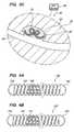
- FIGS. 2A and 2Bare side views of an exemplary embodiment of a vaso-occlusive device constructed in accordance with the invention.
- FIGS. 3A-3Care cross-sectional views of a patient's body, illustrating a method for treating an aneurysm performed in accordance with embodiments of the invention.
- FIGS. 4A and 4Bare partial cross-sectional views of further exemplary embodiments of vaso-occlusive devices constructed in accordance with a further aspect of the invention.
- FIGS. 1A and 1Bdepict a system 10 for embolizing and/or occluding a cavity within a body 90 , e.g., an aneurysm 92 extending from a blood vessel 94 .
- the system 10includes a vaso-occlusive device 20 , a delivery catheter 30 , and a magnetic resonance imaging (“MRI”) machine 40 .
- MRImagnetic resonance imaging
- the vaso-occlusive device 20includes an elongate helical coil 22 that assumes a delivery configuration (shown in FIG. 2A ) when constrained in the delivery catheter 30 , and a three-dimensional deployed configuration (shown in FIG. 2B ) when placed in a body cavity, e.g., in aneurysm 92 .
- the coil 22may be formed by first winding a small, flexible wire into a linear helical form defining the delivery configuration, using known heat treatment methods.
- the coil 22is wound into a deployed configuration, e.g., by winding the coil 22 onto a mandrel (not shown) and heat treating the coil 22 , using known methods.
- a deployed configuratione.g., by winding the coil 22 onto a mandrel (not shown) and heat treating the coil 22 , using known methods.
- the coil 22may be biased to assume a variety of predetermined or random shapes in the deployed configuration.
- a substantially straight wire or filament, or braid of wires or filamentsmay be provided instead of the helical coil configuration. Additional information on methods for manufacturing vaso-occlusive devices suitable for constructing embodiments of the present invention may be found in U.S. Pat. No. 6,322,576 to Wallace et al., the disclosure of which is incorporated herein by reference for all that it teaches and discloses.
- the coil 22may be formed from a variety of materials, e.g., metals, polymers, alloys, or composites thereof.
- the coil 22includes ferrous material, causing the coil 22 to be heated by activation of the MRI machine to apply a variable AC magnetic field on the device after it is implanted at a selected occlusion site in the vasculature.
- the coil 22preferably includes radiopaque material, such as metals and/or polymers.
- Suitable metals and alloys for the wire defining the coil 22may include the platinum group metals, especially platinum, rhodium, palladium, and rhenium, as well as tungsten, gold, silver, tantalum, and alloys of these metals. These metals have significant radiopacity and their alloys may be tailored to accomplish an appropriate blend of flexibility and stiffness for the coil 22 . They are also generally biologically inert. A platinum/tungsten alloy may be most preferred, with ferrous material mixed with or carried by the alloy. Additional suitable materials are described in the above-incorporated U.S. Pat. No. 6,322,576.
- the coil 22may include radiolucent fibers or polymers (or metallic threads coated with radiolucent or radiopaque fibers), such as Dacron (polyester), polyglycolic acid, polylactic acid, fluoropolymers (polytetrafluoroethylene), NylonTM (polyamide), and/or silk.
- a polymerWhen a polymer is used as the major component of the vaso-occlusive device 20 , it may be filled with some amount of radiopaque material, such as powdered tantalum, tungsten, bismuth oxide, barium sulfate, and the like.
- the ferrous materiale.g., iron particles, filaments and the like, may be mixed with and/or embedded in the polymer.
- the diameter of the wire defining the coil 22may be between about 0.0005 and 0.006 inch (0.012-0.15 mm).
- the wiremay be wound into a primary coil having a primary diameter between about 0.005 and 0.025 inch (0.125-0.625 mm), and preferably between about 0.010 and 0.018 inch (0.25-0.45 mm).
- Such wiremay be of an appropriate diameter to provide sufficient hoop strength to hold the vaso-occlusive device 20 in place within a chosen body cavity without distending the wall of the cavity and/or without moving substantially from the cavity as a result of the repetitive fluid pulsing experienced within the vascular system.
- the axial length of the delivery configuration of the coil 22may be between about one half and one hundred centimeters (0.5-100 cm), and preferably between about two and forty centimeters (2-40 cm).
- the coil 22may have between about ten and seventy five (10-75) turns per centimeter, and preferably between about ten and forty (10-40) turns per centimeter.
- a coatingis provided on the coil 22 , the coating having a melting temperature “T m ” or a glass transition temperature “T g ” that is less than the temperature to which the vaso-occlusive device 20 is heated by the MRI machine 40 .
- the coatingmay have a “T m ” and/or “T g ” of about 80-150° F.
- Suitable polymeric materialsmay include polyalkenes, polymethacrylates, polyacrylates, polyesters, polyamides, and polysaccharides. Co-polymers, blends, alloys, and block copolymers of such materials may also be used. Additional information on suitable coatings are described in the above-incorporated U.S. Pat. Nos. 5,749,894 and 6,187,024.
- the coatingcomprises, or otherwise covers, one or more agents, e.g., a bioactive agent, a collagenous material, and/or other diagnostic or therapeutic agent(s).
- agentse.g., a bioactive agent, a collagenous material, and/or other diagnostic or therapeutic agent(s).
- bioactive agentsmay include genes, growth factors, biomolecules, peptides, oligonucleotides, members of the integrin family, RGD-containing sequences, oligopeptides, fibronectin, laminin, bitronectin, hyaluronic acid, silk-elastin, elastin, fibrinogen, and other basement membrane proteins with bioactive agents.
- the agent(s)may be applied in a first coating on the coil 22 , with a second coating, such as the polymeric materials described above, applied to substantially cover or otherwise embed the agent(s) from exposure to the blood pool and body tissue at the deployment site in the vasculature.
- the vaso-occlusive device 20e.g., coli 22
- the vaso-occlusive device 20may itself be formed from a polymeric material having with one or more embedded diagnostic and/or therapeutic agents that are released by heating of the device, as described in greater detail below.
- one or more agent(s)may be carried on, or otherwise embedded in, the vaso-occlusive device 20 without being initially exposed or otherwise released or activated in the body upon implantation of the device.
- Thiscan be advantageous, e.g., for preventing the agent(s) from release or activation if the vaso-occlusive device 20 is exposed within a blood vessel or other body region where embolization or other treatment effects are undesired. Only when the coating and/or the coil itself is heated above its melting and/or glass transition temperature, e.g., when it is determined that the implant device is placed where desired in the body cavity, are the agent(s) released or otherwise activated.
- the agentsmay be prevented from making contact with the blood/tissue in the body cavity until released by the heating of the implant device (as described above). Additionally or alternatively, the agents may be exposed to the blood/tissue in the cavity, but dormant until heated (i.e., by conductive heating from the heated ferrous material) above a critical temperature threshold, activating (with the heat as the catalyst) the bioactive agent.
- the MRI machine 40includes a static field magnet 42 , a gradient field amplifier 44 and a radio frequency (“RF”) transmitter/receiver 46 .
- the magnet 42includes an internal lumen region for receiving the patient 90 , and may provide a static, relatively homogeneous magnetic field over the patient 90 .
- an open-MRI machine or other MR devicemay be used, as is well-known.
- the gradient field amplifier 44generates variable AC magnetic field gradients that vary the static magnetic field
- the RF transmitter 46transmits RF pulse sequences over the patient's body to cause the patient's tissues to emit MR response signals.
- the MR response signalsmay be used to generate images of the patient's body 90 , as is well-known.
- the variable AC magnetic field generated by the magnet 42 and gradient field amplifier 44will agitate the ferrous material in the vaso-occlusive device 20 , thereby causing the ferrous material to heat.
- Other portions of the vaso-occlusive device 20e.g., a coating and/or polymeric material defining the coil 22 itself, are heated by conduction from the heated ferrous material above their “T m ” and/or “T g ,” causing the coating and/or polymeric material portions to at least partially melt or soften.
- heat generated by the interaction between the MRI device 40 and the ferrous material in the vaso-occlusive device 20heats the surrounding blood or tissue to enhance embolization of the site and/or promote improved long term healing of the embolism and/or surrounding aneurysmal tissue.
- a coating on the occlusive devicemay itself include ferrous material.
- variable AC magnetic fieldcan heat the ferrous material through at least two mechanisms.
- the materialcan be heated due to hysteresis losses associated with the material being alternatively energized with positive and negative energy fields; i.e., as some materials are less efficient in responding to the alternating polarization, resulting in current losses which produce heat.
- Materials that are poor conductors, such as ferrous materialsproduce more heat effects than highly conductive materials such as copper, platinum or aluminum.
- Other factors that effect hysteresis lossesinclude the flux density and the MR frequency of the selected materials.
- a second mechanism for the generation of heatinvolves conduction losses.
- the MR machineproduces a conduction field around the device, thereby producing a voltage potential across the device. This voltage potential produces eddy currents in the occlusive device.
- Some materials and some implant device constructionsare more conductive than others. Less conductive implants will result in more heat being generated.
- flat ribbon material, rather than round wire stock,will increase resistance (and, thus, heating), as will using ferrous materials over conductive materials such as copper, platinum or aluminum.
- the vaso-occlusive device 20may include a bioactive agent, collagenous material, and/or other therapeutic and/or diagnostic agent embedded within or beneath a coating on the coil 22 .
- the delivery catheter 30is introduced into the patient's body 90 from a percutaneous entry site into a peripheral artery, such as the femoral or carotid arteries (not shown), as is well-known.
- the delivery catheter 30may be advanced over a guidewire or other rail (not shown) previously placed within the patient's vasculature using known methods.
- the delivery catheter 30is advanced through the patient's vasculature, until a distal end 32 of the catheter 30 is disposed within a blood vessel 94 adjacent the aneurysm 92 .
- the vaso-occlusive device 20is advanced through a lumen 34 of the catheter 30 into the aneurysm 92 , as shown in FIG. 3A .
- the vaso-occlusive device 20assume a three-dimensional, deployed configuration.
- the deployed configurationis selected such that the vaso-occlusive device 20 substantially fills the aneurysm 92 .
- a treating physicianwill deploy multiple occlusive devices into a single aneurysm, as is well-known. Additional information on apparatus and methods that may be suitable for delivering the vaso-occlusive coil 20 is found in U.S. Pat. No. 4,994,069 to Ritchart et al., which is incorporated by reference herein for all it teaches and discloses, as well as the other above-incorporated U.S. patents.
- the MRI machine 40is activated to at least partially melt or sufficiently soften the coating on the coil 22 . This may involve transferring the patient 90 from a catheter lab or other location where the vaso-occlusive device 20 was implanted into a MRI room.
- the gradient field amplifier 44(not shown in FIG. 3C , see FIG. 1A ) is activated to generate magnetic energy (represented by arrows 48 in FIG. 3C ), which interacts with ferrous material in the coil 22 and/or coating to heat the vaso-occlusive device 20 .
- the MRI machine 40is activated for a predetermined time, e.g., between about 3 seconds to 20 minutes, to heat the vaso-occlusive device 20 and/or coating to a desired temperature.
- the vaso-occlusive device and/or coatingmay be heated to a temperature of at least about 150° F. (about 40° C.).
- the coatingmay melt and/or flow, thereby releasing or otherwise activating one or more diagnostic or therapeutic agent(s) 28 carried in or beneath the coating.
- the coatingmay include a thrombogenic agent that enhances embolization of blood when released within the aneurysm 92 .
- the coatingmay include one or more agents that remain substantially inert until heated above a predetermined activation temperature.
- the MRI machine 40may be activated for the to heat the vaso-occlusive device 20 in order to heat blood or other material within the aneurysm 92 and/or tissue surrounding the aneurysm 92 , even in the absence of such agent(s). Such heating may accelerate coagulation of blood or other fluid within the aneurysm 92 and/or may cause the surrounding tissue to contract, e.g., to reduce the size of the aneurysm 92 , and promote an improved long term healing response.
- At least a portion of the vaso-occlusive device 20is formed from a material that melts or is otherwise sufficiently softened when heated.
- the MRI machine 40is activated for sufficient time to cause at least a portion of a coating and/or coil of the vaso-occlusive device 20 to melt and/or flow together.
- the coilcools, and substantially solidifies, thereby fusing together melted/softened portions of the vaso-occlusive device 20 in its deployed configuration in the aneurysm 92 . This fusion stabilizes the vaso-occlusive device 20 in its deployed configuration, helping prevent the device from moving back towards a delivery and/or other generally linear shape.
- FIGS. 4A and 4Bare partial cross-sections (or cutaways) of further embodiments of MR-activated, embolic implant devices 100 and 100 ′, respectively, constructed in accordance with a further aspect of the present invention.
- the devices 100 and 100 ′are each made up of a helically wound occlusive coil 102 having a first end 104 and a second end 106 . While the coil 102 is depicted in FIGS. 4A and 4B as made from a round wire, i.e., having a substantially circular cross-section, the coil 102 may alternatively be made from a differently shaped wire, e.g., a flat wire having a rectangular cross-section.
- the coil 102is preferably made of platinum, and may be provided with a heat-releasable and/or activated agent coating (not shown), as discussed above. Additionally or alternately, a heat-releasable and/or activated agent coating may be provided on the filament 108 , 114 .
- the coil 102forms a central lumen, through which a ferrous material filament 108 ( FIG. 4A ), 114 ( FIG. 4B ) is located, the filament being fixed to the respective first and second ends 104 and 106 of the coil 102 .
- the filament 108 , 114acts as a heating element upon application of an AC magnetic field by an MRI machine, as discussed above.
- the highly conductive (preferably platinum) coil 102generates a corresponding highly efficient induction field, which heats the highly resistive ferrous material filament 108 , 114 in the coil lumen. Thermal energy in the heated filament is then transferred by convection to the coil 102 and surrounding blood pool and tissue, which has the benefits/effects previously described.
- At least a portion of the coil 102may be formed from a material that melts or substantially softens when heated, as described above.
- fusing points of the coil 102 in its deployed configurationmay be determined by locations that the ferrous filament is attached, since these attachment points on the coil 102 will heat the most. It will be appreciated from the present disclosure that the features of a heat-releasable and/or activated agent and structural fusing of the occlusive coil may be provided separately or together in a single, implantable device.
- the filament 108 , 114may also (optionally) serve as a stretch resisting member, as taught, for example, in U.S. Pat. No. 5,853,418, which is fully incorporated by reference herein for all that it teaches and discloses. In certain circumstances, it may be desirable to attach the filament 108 , 114 only to one of the two ends 104 , 106 , or alternately (or additionally) to at least one site between the to ends, or to neither of the two ends. Of course, for attaining stretch resistance, if so desired, the filament 108 , 114 must be attached to at least two points on the coil 102 .
- the ferrous filament 108 , 114may be constructed in various ways.
- the filament 108 , 114may comprise thermoplastic or thermosetting having a bundle of threads or a single filament with one or more metallic ferrous strands formed therein.
- the filament 108 of the variation shown in FIG. 4Ais formed as a ribbon; the filament 114 shown in FIG. 4B is formed as a helically wound coil; in both cases that is soldered, brazed, glued, or otherwise fixedly attached to the first and second coil ends 104 and 106 .
- an ultrasound device(not shown) may be provided, e.g., including a piezoelectric transducer that may be placed in contact with the patient's skin overlying an aneurysm, lumen, or other cavity where a vaso-occlusive device has been implanted.
- an acoustic gel or other materialmay be provided between the transducer and the patient's skin to enhance acoustically coupling the transducer to the patient, as is known in the art.
- Acoustic energymay be delivered from the ultrasound device through the patient's skin and intervening tissue to the cavity to heat the vaso-occlusive device.
- the energymay be focused or generally directed into the patient's body using known methods.
- the acoustic energymay be transferred to heat energy when it is absorbed by the vaso-occlusive device and/or surrounding tissue to heat the vaso-occlusive device.
- the vaso-occlusive devicemay include materials that enhance acoustic energy absorption and/or attenuation in a predetermined manner to ensure adequate heating of the vaso-occlusive device.
- a source of electrical energye.g., a radio frequency (“RF”) generator
- RFradio frequency
- Electrical energymay be delivered into the patient's body to inductively heat the vaso-occlusive device, as is known to those skilled in the art.
Landscapes
- Health & Medical Sciences (AREA)
- Surgery (AREA)
- Life Sciences & Earth Sciences (AREA)
- Heart & Thoracic Surgery (AREA)
- Molecular Biology (AREA)
- Vascular Medicine (AREA)
- Engineering & Computer Science (AREA)
- Biomedical Technology (AREA)
- Reproductive Health (AREA)
- Medical Informatics (AREA)
- Nuclear Medicine, Radiotherapy & Molecular Imaging (AREA)
- Animal Behavior & Ethology (AREA)
- General Health & Medical Sciences (AREA)
- Public Health (AREA)
- Veterinary Medicine (AREA)
- Neurosurgery (AREA)
- Surgical Instruments (AREA)
Abstract
Description
Claims (13)
Priority Applications (2)
| Application Number | Priority Date | Filing Date | Title |
|---|---|---|---|
| US10/669,543US7789891B2 (en) | 2003-09-23 | 2003-09-23 | External activation of vaso-occlusive implants |
| US12/873,008US8226680B2 (en) | 2003-09-23 | 2010-08-31 | System for embolizing a target site in a body by application of an external energy |
Applications Claiming Priority (1)
| Application Number | Priority Date | Filing Date | Title |
|---|---|---|---|
| US10/669,543US7789891B2 (en) | 2003-09-23 | 2003-09-23 | External activation of vaso-occlusive implants |
Related Child Applications (1)
| Application Number | Title | Priority Date | Filing Date |
|---|---|---|---|
| US12/873,008ContinuationUS8226680B2 (en) | 2003-09-23 | 2010-08-31 | System for embolizing a target site in a body by application of an external energy |
Publications (2)
| Publication Number | Publication Date |
|---|---|
| US20050065545A1 US20050065545A1 (en) | 2005-03-24 |
| US7789891B2true US7789891B2 (en) | 2010-09-07 |
Family
ID=34313723
Family Applications (2)
| Application Number | Title | Priority Date | Filing Date |
|---|---|---|---|
| US10/669,543Expired - Fee RelatedUS7789891B2 (en) | 2003-09-23 | 2003-09-23 | External activation of vaso-occlusive implants |
| US12/873,008Expired - Fee RelatedUS8226680B2 (en) | 2003-09-23 | 2010-08-31 | System for embolizing a target site in a body by application of an external energy |
Family Applications After (1)
| Application Number | Title | Priority Date | Filing Date |
|---|---|---|---|
| US12/873,008Expired - Fee RelatedUS8226680B2 (en) | 2003-09-23 | 2010-08-31 | System for embolizing a target site in a body by application of an external energy |
Country Status (1)
| Country | Link |
|---|---|
| US (2) | US7789891B2 (en) |
Cited By (10)
| Publication number | Priority date | Publication date | Assignee | Title |
|---|---|---|---|---|
| US20090163986A1 (en)* | 2007-12-21 | 2009-06-25 | Microvention, Inc | System And Method Of Detecting Implant Detachment |
| US20100331666A1 (en)* | 2003-09-23 | 2010-12-30 | Boston Scientific Scimed, Inc. | System for embolizing a target site in a body by application of an external energy |
| US20110245862A1 (en)* | 2006-08-17 | 2011-10-06 | Tsunami Innovations Llc | Isolation devices for the treatment of aneurysms |
| US9242070B2 (en) | 2007-12-21 | 2016-01-26 | MicronVention, Inc. | System and method for locating detachment zone of a detachable implant |
| WO2017083753A1 (en) | 2015-11-12 | 2017-05-18 | Herr John C | Compositions and methods for vas-occlusive contraception and reversal thereof |
| US10188395B2 (en) | 2015-12-16 | 2019-01-29 | DePuy Synthes Products, Inc. | Non-planar heating chamber detachment mechanism of an implantable vaso-occluding device delivery system |
| US10751124B2 (en) | 2017-01-05 | 2020-08-25 | Contraline, Inc. | Methods for implanting and reversing stimuli-responsive implants |
| US11253391B2 (en) | 2018-11-13 | 2022-02-22 | Contraline, Inc. | Systems and methods for delivering biomaterials |
| US12114863B2 (en) | 2018-12-05 | 2024-10-15 | Microvention, Inc. | Implant delivery system |
| US12383421B2 (en) | 2017-01-05 | 2025-08-12 | Contraline, Inc. | Contraceptive devices |
Families Citing this family (100)
| Publication number | Priority date | Publication date | Assignee | Title |
|---|---|---|---|---|
| US7807211B2 (en) | 1999-09-03 | 2010-10-05 | Advanced Cardiovascular Systems, Inc. | Thermal treatment of an implantable medical device |
| US20070032853A1 (en) | 2002-03-27 | 2007-02-08 | Hossainy Syed F | 40-O-(2-hydroxy)ethyl-rapamycin coated stent |
| US7155516B2 (en) | 2000-02-08 | 2006-12-26 | Mips Technologies, Inc. | Method and apparatus for overflowing data packets to a software-controlled memory when they do not fit into a hardware-controlled memory |
| US6953560B1 (en) | 2000-09-28 | 2005-10-11 | Advanced Cardiovascular Systems, Inc. | Barriers for polymer-coated implantable medical devices and methods for making the same |
| US6783793B1 (en) | 2000-10-26 | 2004-08-31 | Advanced Cardiovascular Systems, Inc. | Selective coating of medical devices |
| US7862495B2 (en) | 2001-05-31 | 2011-01-04 | Advanced Cardiovascular Systems, Inc. | Radiation or drug delivery source with activity gradient to minimize edge effects |
| US6656216B1 (en)* | 2001-06-29 | 2003-12-02 | Advanced Cardiovascular Systems, Inc. | Composite stent with regioselective material |
| US6896965B1 (en)* | 2002-11-12 | 2005-05-24 | Advanced Cardiovascular Systems, Inc. | Rate limiting barriers for implantable devices |
| US8435550B2 (en) | 2002-12-16 | 2013-05-07 | Abbot Cardiovascular Systems Inc. | Anti-proliferative and anti-inflammatory agent combination for treatment of vascular disorders with an implantable medical device |
| US20060002968A1 (en) | 2004-06-30 | 2006-01-05 | Gordon Stewart | Anti-proliferative and anti-inflammatory agent combination for treatment of vascular disorders |
| US7758881B2 (en) | 2004-06-30 | 2010-07-20 | Advanced Cardiovascular Systems, Inc. | Anti-proliferative and anti-inflammatory agent combination for treatment of vascular disorders with an implantable medical device |
| US7063884B2 (en) | 2003-02-26 | 2006-06-20 | Advanced Cardiovascular Systems, Inc. | Stent coating |
| US20050118344A1 (en) | 2003-12-01 | 2005-06-02 | Pacetti Stephen D. | Temperature controlled crimping |
| US20050065501A1 (en)* | 2003-09-23 | 2005-03-24 | Scimed Life Systems, Inc. | Energy activated vaso-occlusive devices |
| US7198675B2 (en) | 2003-09-30 | 2007-04-03 | Advanced Cardiovascular Systems | Stent mandrel fixture and method for selectively coating surfaces of a stent |
| US7563324B1 (en) | 2003-12-29 | 2009-07-21 | Advanced Cardiovascular Systems Inc. | System and method for coating an implantable medical device |
| US7553377B1 (en) | 2004-04-27 | 2009-06-30 | Advanced Cardiovascular Systems, Inc. | Apparatus and method for electrostatic coating of an abluminal stent surface |
| US7377941B2 (en)* | 2004-06-29 | 2008-05-27 | Micardia Corporation | Adjustable cardiac valve implant with selective dimensional adjustment |
| US8709469B2 (en) | 2004-06-30 | 2014-04-29 | Abbott Cardiovascular Systems Inc. | Anti-proliferative and anti-inflammatory agent combination for treatment of vascular disorders with an implantable medical device |
| US7648727B2 (en) | 2004-08-26 | 2010-01-19 | Advanced Cardiovascular Systems, Inc. | Methods for manufacturing a coated stent-balloon assembly |
| US20060206140A1 (en)* | 2005-02-24 | 2006-09-14 | Samuel Shaolian | Adjustable embolic aneurysm coil |
| US7795467B1 (en) | 2005-04-26 | 2010-09-14 | Advanced Cardiovascular Systems, Inc. | Bioabsorbable, biobeneficial polyurethanes for use in medical devices |
| US8778375B2 (en) | 2005-04-29 | 2014-07-15 | Advanced Cardiovascular Systems, Inc. | Amorphous poly(D,L-lactide) coating |
| US7637941B1 (en) | 2005-05-11 | 2009-12-29 | Advanced Cardiovascular Systems, Inc. | Endothelial cell binding coatings for rapid encapsulation of bioerodable stents |
| US8021676B2 (en) | 2005-07-08 | 2011-09-20 | Advanced Cardiovascular Systems, Inc. | Functionalized chemically inert polymers for coatings |
| US7785647B2 (en)* | 2005-07-25 | 2010-08-31 | Advanced Cardiovascular Systems, Inc. | Methods of providing antioxidants to a drug containing product |
| US20070128246A1 (en)* | 2005-12-06 | 2007-06-07 | Hossainy Syed F A | Solventless method for forming a coating |
| US7591841B2 (en) | 2005-12-16 | 2009-09-22 | Advanced Cardiovascular Systems, Inc. | Implantable devices for accelerated healing |
| US7976891B1 (en) | 2005-12-16 | 2011-07-12 | Advanced Cardiovascular Systems, Inc. | Abluminal stent coating apparatus and method of using focused acoustic energy |
| US7867547B2 (en) | 2005-12-19 | 2011-01-11 | Advanced Cardiovascular Systems, Inc. | Selectively coating luminal surfaces of stents |
| US7638156B1 (en) | 2005-12-19 | 2009-12-29 | Advanced Cardiovascular Systems, Inc. | Apparatus and method for selectively coating a medical article |
| US20070196428A1 (en)* | 2006-02-17 | 2007-08-23 | Thierry Glauser | Nitric oxide generating medical devices |
| US7601383B2 (en)* | 2006-02-28 | 2009-10-13 | Advanced Cardiovascular Systems, Inc. | Coating construct containing poly (vinyl alcohol) |
| US7713637B2 (en)* | 2006-03-03 | 2010-05-11 | Advanced Cardiovascular Systems, Inc. | Coating containing PEGylated hyaluronic acid and a PEGylated non-hyaluronic acid polymer |
| US8888800B2 (en) | 2006-03-13 | 2014-11-18 | Pneumrx, Inc. | Lung volume reduction devices, methods, and systems |
| US20070231363A1 (en)* | 2006-03-29 | 2007-10-04 | Yung-Ming Chen | Coatings formed from stimulus-sensitive material |
| US20070259101A1 (en)* | 2006-05-02 | 2007-11-08 | Kleiner Lothar W | Microporous coating on medical devices |
| US8304012B2 (en)* | 2006-05-04 | 2012-11-06 | Advanced Cardiovascular Systems, Inc. | Method for drying a stent |
| US8003156B2 (en) | 2006-05-04 | 2011-08-23 | Advanced Cardiovascular Systems, Inc. | Rotatable support elements for stents |
| US7985441B1 (en) | 2006-05-04 | 2011-07-26 | Yiwen Tang | Purification of polymers for coating applications |
| US7775178B2 (en)* | 2006-05-26 | 2010-08-17 | Advanced Cardiovascular Systems, Inc. | Stent coating apparatus and method |
| US8568764B2 (en) | 2006-05-31 | 2013-10-29 | Advanced Cardiovascular Systems, Inc. | Methods of forming coating layers for medical devices utilizing flash vaporization |
| US9561351B2 (en)* | 2006-05-31 | 2017-02-07 | Advanced Cardiovascular Systems, Inc. | Drug delivery spiral coil construct |
| US8703167B2 (en) | 2006-06-05 | 2014-04-22 | Advanced Cardiovascular Systems, Inc. | Coatings for implantable medical devices for controlled release of a hydrophilic drug and a hydrophobic drug |
| US20070286882A1 (en)* | 2006-06-09 | 2007-12-13 | Yiwen Tang | Solvent systems for coating medical devices |
| US8778376B2 (en)* | 2006-06-09 | 2014-07-15 | Advanced Cardiovascular Systems, Inc. | Copolymer comprising elastin pentapeptide block and hydrophilic block, and medical device and method of treating |
| US8603530B2 (en) | 2006-06-14 | 2013-12-10 | Abbott Cardiovascular Systems Inc. | Nanoshell therapy |
| US8114150B2 (en) | 2006-06-14 | 2012-02-14 | Advanced Cardiovascular Systems, Inc. | RGD peptide attached to bioabsorbable stents |
| US8048448B2 (en) | 2006-06-15 | 2011-11-01 | Abbott Cardiovascular Systems Inc. | Nanoshells for drug delivery |
| US8017237B2 (en) | 2006-06-23 | 2011-09-13 | Abbott Cardiovascular Systems, Inc. | Nanoshells on polymers |
| US9028859B2 (en) | 2006-07-07 | 2015-05-12 | Advanced Cardiovascular Systems, Inc. | Phase-separated block copolymer coatings for implantable medical devices |
| US8703169B1 (en) | 2006-08-15 | 2014-04-22 | Abbott Cardiovascular Systems Inc. | Implantable device having a coating comprising carrageenan and a biostable polymer |
| WO2008053469A2 (en)* | 2006-10-29 | 2008-05-08 | Alon Shalev | An extra-vascular wrapping for treating aneurysmatic aorta and methods thereof |
| US8597673B2 (en)* | 2006-12-13 | 2013-12-03 | Advanced Cardiovascular Systems, Inc. | Coating of fast absorption or dissolution |
| ES2624595T3 (en) | 2007-03-05 | 2017-07-17 | Endospan Ltd | Bifurcated, supportive, expandable endoluminal grafts with multiple components and methods for use |
| US8147769B1 (en) | 2007-05-16 | 2012-04-03 | Abbott Cardiovascular Systems Inc. | Stent and delivery system with reduced chemical degradation |
| US9056155B1 (en) | 2007-05-29 | 2015-06-16 | Abbott Cardiovascular Systems Inc. | Coatings having an elastic primer layer |
| US8048441B2 (en) | 2007-06-25 | 2011-11-01 | Abbott Cardiovascular Systems, Inc. | Nanobead releasing medical devices |
| US8109904B1 (en) | 2007-06-25 | 2012-02-07 | Abbott Cardiovascular Systems Inc. | Drug delivery medical devices |
| CN101965162B (en) | 2007-12-15 | 2014-12-10 | 恩多斯潘有限公司 | Extra-vascular wrapping for treating aneurysmatic aorta in conjunction with endovascular stent-graft and methods thereof |
| US8241324B2 (en)* | 2008-03-03 | 2012-08-14 | Eilaz Babaev | Ultrasonic vascular closure device |
| CA3009244C (en) | 2009-06-23 | 2020-04-28 | Endospan Ltd. | Vascular prostheses for treating aneurysms |
| WO2011004374A1 (en) | 2009-07-09 | 2011-01-13 | Endospan Ltd. | Apparatus for closure of a lumen and methods of using the same |
| CN102740807B (en) | 2009-11-30 | 2015-11-25 | 恩多斯潘有限公司 | Multi-component stent-graft system for implantation into vessels with multiple branches |
| EP2509535B1 (en) | 2009-12-08 | 2016-12-07 | Endospan Ltd | Endovascular stent-graft system with fenestrated and crossing stent-grafts |
| WO2011080738A1 (en) | 2009-12-31 | 2011-07-07 | Endospan Ltd. | Endovascular flow direction indicator |
| US9468517B2 (en) | 2010-02-08 | 2016-10-18 | Endospan Ltd. | Thermal energy application for prevention and management of endoleaks in stent-grafts |
| CA2826022A1 (en) | 2011-02-03 | 2012-08-09 | Endospan Ltd. | Implantable medical devices constructed of shape memory material |
| US9888530B2 (en) | 2011-02-14 | 2018-02-06 | Bernard Fryshman | Induction cooking apparatus and induction cookware |
| US9131536B2 (en) | 2011-02-14 | 2015-09-08 | Bernard Fryshman | Induction cooking apparatus and method of use |
| WO2012111006A1 (en) | 2011-02-17 | 2012-08-23 | Endospan Ltd. | Vascular bands and delivery systems therefor |
| WO2012117395A1 (en) | 2011-03-02 | 2012-09-07 | Endospan Ltd. | Reduced-strain extra- vascular ring for treating aortic aneurysm |
| US8574287B2 (en) | 2011-06-14 | 2013-11-05 | Endospan Ltd. | Stents incorporating a plurality of strain-distribution locations |
| US8951298B2 (en) | 2011-06-21 | 2015-02-10 | Endospan Ltd. | Endovascular system with circumferentially-overlapping stent-grafts |
| US9254209B2 (en) | 2011-07-07 | 2016-02-09 | Endospan Ltd. | Stent fixation with reduced plastic deformation |
| US9839510B2 (en) | 2011-08-28 | 2017-12-12 | Endospan Ltd. | Stent-grafts with post-deployment variable radial displacement |
| US9427339B2 (en) | 2011-10-30 | 2016-08-30 | Endospan Ltd. | Triple-collar stent-graft |
| JP5899864B2 (en)* | 2011-11-22 | 2016-04-06 | 国立大学法人京都大学 | Embolization coil |
| US9597204B2 (en) | 2011-12-04 | 2017-03-21 | Endospan Ltd. | Branched stent-graft system |
| US9427172B2 (en)* | 2011-12-30 | 2016-08-30 | Mediguide Ltd. | Roll detection and six degrees of freedom sensor assembly |
| WO2013171730A1 (en) | 2012-05-15 | 2013-11-21 | Endospan Ltd. | Stent-graft with fixation elements that are radially confined for delivery |
| US10052097B2 (en) | 2012-07-26 | 2018-08-21 | Nyxoah SA | Implant unit delivery tool |
| EP2877239B1 (en) | 2012-07-26 | 2023-06-21 | Nyxoah SA | Electrical contacts on a medical device patch |
| US9993360B2 (en) | 2013-01-08 | 2018-06-12 | Endospan Ltd. | Minimization of stent-graft migration during implantation |
| US9668892B2 (en) | 2013-03-11 | 2017-06-06 | Endospan Ltd. | Multi-component stent-graft system for aortic dissections |
| US10161390B2 (en)* | 2013-03-14 | 2018-12-25 | Lawrence Livermore National Security, Llc | Bidirectional shape memory device |
| EP3027124B1 (en) | 2013-07-31 | 2022-01-12 | Embolic Acceleration, LLC | Devices for endovascular embolization |
| US10010328B2 (en) | 2013-07-31 | 2018-07-03 | NeuVT Limited | Endovascular occlusion device with hemodynamically enhanced sealing and anchoring |
| WO2015075708A1 (en) | 2013-11-19 | 2015-05-28 | Endospan Ltd. | Stent system with radial-expansion locking |
| WO2016070009A1 (en) | 2014-10-31 | 2016-05-06 | Medtronic Advanced Energy Llc | Power monitoring circuitry and method for reducing leakage current in rf generators |
| CN106029005B (en) | 2014-12-18 | 2018-01-19 | 恩都思潘有限公司 | The Endovascular stent-graft of horizontal conduit with tired resistance |
| EP3266389A4 (en)* | 2015-03-03 | 2018-11-21 | Kaneka Medix Corporation | Vascular embolization tool and production method therefor |
| US20170019957A1 (en)* | 2015-07-17 | 2017-01-19 | Bernard Fryshman | Induction cooking and heating systems |
| US10105069B2 (en) | 2016-04-20 | 2018-10-23 | Bernard Fryshman | Induction heating applications |
| US10328249B2 (en) | 2017-05-02 | 2019-06-25 | Bernard Fryshman | Applications using induction |
| WO2019118374A1 (en)* | 2017-12-12 | 2019-06-20 | Penumbra, Inc. | Vascular cages and methods of making and using the same |
| IT201800002332A1 (en)* | 2018-02-02 | 2019-08-02 | Amista Pietro | INTRANEURISMATIC DEVICE FOR THE TREATMENT OF ANEURISMS |
| EP3897370B1 (en)* | 2018-12-21 | 2025-06-11 | W. L. Gore & Associates, Inc. | Medical treatment system using measurement data from multiple sensors |
| US11612678B2 (en)* | 2019-09-11 | 2023-03-28 | Stryker Corporation | Intravascular devices |
| US11484629B2 (en) | 2019-09-11 | 2022-11-01 | Stryker Corporation | Intravascular devices with high tungsten content |
Citations (42)
| Publication number | Priority date | Publication date | Assignee | Title |
|---|---|---|---|---|
| US4994069A (en) | 1988-11-02 | 1991-02-19 | Target Therapeutics | Vaso-occlusion coil and method |
| US5257635A (en) | 1988-11-25 | 1993-11-02 | Sensor Electronics, Inc. | Electrical heating catheter |
| US5304194A (en) | 1991-10-02 | 1994-04-19 | Target Therapeutics | Vasoocclusion coil with attached fibrous element(s) |
| JPH0718357A (en) | 1991-10-02 | 1995-01-20 | Yasubumi Furuya | Combined functional material device |
| US5405322A (en)* | 1993-08-12 | 1995-04-11 | Boston Scientific Corporation | Method for treating aneurysms with a thermal source |
| US5507744A (en) | 1992-04-23 | 1996-04-16 | Scimed Life Systems, Inc. | Apparatus and method for sealing vascular punctures |
| US5624461A (en) | 1995-06-06 | 1997-04-29 | Target Therapeutics, Inc. | Three dimensional in-filling vaso-occlusive coils |
| US5639277A (en) | 1995-04-28 | 1997-06-17 | Target Therapeutics, Inc. | Embolic coils with offset helical and twisted helical shapes |
| US5649949A (en) | 1996-03-14 | 1997-07-22 | Target Therapeutics, Inc. | Variable cross-section conical vasoocclusive coils |
| US5669931A (en) | 1995-03-30 | 1997-09-23 | Target Therapeutics, Inc. | Liquid coils with secondary shape |
| US5749894A (en)* | 1996-01-18 | 1998-05-12 | Target Therapeutics, Inc. | Aneurysm closure method |
| US5824049A (en)* | 1995-06-07 | 1998-10-20 | Med Institute, Inc. | Coated implantable medical device |
| US5853418A (en)* | 1995-06-30 | 1998-12-29 | Target Therapeutics, Inc. | Stretch resistant vaso-occlusive coils (II) |
| US5941888A (en) | 1998-02-18 | 1999-08-24 | Target Therapeutics, Inc. | Vaso-occlusive member assembly with multiple detaching points |
| US5944733A (en) | 1997-07-14 | 1999-08-31 | Target Therapeutics, Inc. | Controlled detachable vasoocclusive member using mechanical junction and friction-enhancing member |
| US5989242A (en) | 1995-06-26 | 1999-11-23 | Trimedyne, Inc. | Therapeutic appliance releasing device |
| US6019757A (en) | 1995-07-07 | 2000-02-01 | Target Therapeutics, Inc. | Endoluminal electro-occlusion detection apparatus and method |
| US6102917A (en) | 1998-07-15 | 2000-08-15 | The Regents Of The University Of California | Shape memory polymer (SMP) gripper with a release sensing system |
| US6149664A (en) | 1998-08-27 | 2000-11-21 | Micrus Corporation | Shape memory pusher introducer for vasoocclusive devices |
| WO2000072781A2 (en) | 1999-06-02 | 2000-12-07 | Sethel Interventional, Inc. | Intracorporeal occlusive device |
| US6165198A (en) | 1994-12-13 | 2000-12-26 | Medtronic, Inc. | Embolic elements and methods and apparatus for their delivery |
| US6187024B1 (en) | 1998-11-10 | 2001-02-13 | Target Therapeutics, Inc. | Bioactive coating for vaso-occlusive devices |
| US6221066B1 (en) | 1999-03-09 | 2001-04-24 | Micrus Corporation | Shape memory segmented detachable coil |
| US6270495B1 (en) | 1996-02-22 | 2001-08-07 | Radiotherapeutics Corporation | Method and device for enhancing vessel occlusion |
| US6277125B1 (en) | 1998-10-05 | 2001-08-21 | Cordis Neurovascular, Inc. | Embolic coil deployment system with retaining jaws |
| US6280457B1 (en) | 1999-06-04 | 2001-08-28 | Scimed Life Systems, Inc. | Polymer covered vaso-occlusive devices and methods of producing such devices |
| US20010041898A1 (en) | 1998-10-05 | 2001-11-15 | Barry David C. | Heated vascular occlusion coil deployment system |
| US6322576B1 (en) | 1997-08-29 | 2001-11-27 | Target Therapeutics, Inc. | Stable coil designs |
| WO2002039911A2 (en) | 2000-11-15 | 2002-05-23 | Scimed Life Systems Inc. | Implantable devices with polymeric detachment junction |
| US6397107B1 (en)* | 1998-04-27 | 2002-05-28 | Bokwang Co., Ltd. | Apparatus for embolic treatment using high frequency induction heating |
| US20020138134A1 (en) | 2000-12-29 | 2002-09-26 | Kim Young Kon | Thermostent for biomedical use |
| US6458127B1 (en) | 1999-11-22 | 2002-10-01 | Csaba Truckai | Polymer embolic elements with metallic coatings for occlusion of vascular malformations |
| WO2002087416A2 (en) | 2001-04-26 | 2002-11-07 | Porter Christopher H | Method and apparatus for delivering materials to the body |
| US6478773B1 (en) | 1998-12-21 | 2002-11-12 | Micrus Corporation | Apparatus for deployment of micro-coil using a catheter |
| US6500149B2 (en) | 1998-08-31 | 2002-12-31 | Deepak Gandhi | Apparatus for deployment of micro-coil using a catheter |
| US6544275B1 (en) | 2000-08-11 | 2003-04-08 | Scimed Life Systems, Inc. | Vaso-occlusive coils with selectively flattened areas |
| US6605101B1 (en) | 2000-09-26 | 2003-08-12 | Microvention, Inc. | Microcoil vaso-occlusive device with multi-axis secondary configuration |
| US6605111B2 (en) | 1998-06-04 | 2003-08-12 | New York University | Endovascular thin film devices and methods for treating and preventing stroke |
| US6620152B2 (en) | 1990-03-13 | 2003-09-16 | The Regents Of The University Of California | Method and apparatus for fast electrolyitic detachment of an implant |
| US6740094B2 (en)* | 2000-11-06 | 2004-05-25 | The Regents Of The University Of California | Shape memory polymer actuator and catheter |
| US20040215124A1 (en)* | 2003-04-25 | 2004-10-28 | Medtronic Ave, Inc. | Method and apparatus for aneurismal treatment |
| US20050065545A1 (en) | 2003-09-23 | 2005-03-24 | Scimed Life Systems, Inc. | External activation of vaso-occlusive implants |
Family Cites Families (5)
| Publication number | Priority date | Publication date | Assignee | Title |
|---|---|---|---|---|
| US540532A (en)* | 1895-06-04 | Door-bolt | ||
| US5478773A (en)* | 1994-04-28 | 1995-12-26 | Motorola, Inc. | Method of making an electronic device having an integrated inductor |
| US5824059A (en)* | 1997-08-05 | 1998-10-20 | Wijay; Bandula | Flexible stent |
| JP3815565B2 (en)* | 2003-02-27 | 2006-08-30 | ブラザー工業株式会社 | Embroidery sewing machine |
| JP2007222189A (en)* | 2004-03-29 | 2007-09-06 | Brother Ind Ltd | Cloth holding device |
- 2003
- 2003-09-23USUS10/669,543patent/US7789891B2/ennot_activeExpired - Fee Related
- 2010
- 2010-08-31USUS12/873,008patent/US8226680B2/ennot_activeExpired - Fee Related
Patent Citations (46)
| Publication number | Priority date | Publication date | Assignee | Title |
|---|---|---|---|---|
| US4994069A (en) | 1988-11-02 | 1991-02-19 | Target Therapeutics | Vaso-occlusion coil and method |
| US5257635A (en) | 1988-11-25 | 1993-11-02 | Sensor Electronics, Inc. | Electrical heating catheter |
| US6620152B2 (en) | 1990-03-13 | 2003-09-16 | The Regents Of The University Of California | Method and apparatus for fast electrolyitic detachment of an implant |
| US5304194A (en) | 1991-10-02 | 1994-04-19 | Target Therapeutics | Vasoocclusion coil with attached fibrous element(s) |
| JPH0718357A (en) | 1991-10-02 | 1995-01-20 | Yasubumi Furuya | Combined functional material device |
| US5507744A (en) | 1992-04-23 | 1996-04-16 | Scimed Life Systems, Inc. | Apparatus and method for sealing vascular punctures |
| US5405322A (en)* | 1993-08-12 | 1995-04-11 | Boston Scientific Corporation | Method for treating aneurysms with a thermal source |
| US6165198A (en) | 1994-12-13 | 2000-12-26 | Medtronic, Inc. | Embolic elements and methods and apparatus for their delivery |
| US5669931A (en) | 1995-03-30 | 1997-09-23 | Target Therapeutics, Inc. | Liquid coils with secondary shape |
| US5639277A (en) | 1995-04-28 | 1997-06-17 | Target Therapeutics, Inc. | Embolic coils with offset helical and twisted helical shapes |
| US5624461A (en) | 1995-06-06 | 1997-04-29 | Target Therapeutics, Inc. | Three dimensional in-filling vaso-occlusive coils |
| US5824049A (en)* | 1995-06-07 | 1998-10-20 | Med Institute, Inc. | Coated implantable medical device |
| US5989242A (en) | 1995-06-26 | 1999-11-23 | Trimedyne, Inc. | Therapeutic appliance releasing device |
| US5853418A (en)* | 1995-06-30 | 1998-12-29 | Target Therapeutics, Inc. | Stretch resistant vaso-occlusive coils (II) |
| US6019757A (en) | 1995-07-07 | 2000-02-01 | Target Therapeutics, Inc. | Endoluminal electro-occlusion detection apparatus and method |
| US6024754A (en) | 1996-01-18 | 2000-02-15 | Target Therapeutics Inc. | Aneurysm closure method |
| US5749894A (en)* | 1996-01-18 | 1998-05-12 | Target Therapeutics, Inc. | Aneurysm closure method |
| US6270495B1 (en) | 1996-02-22 | 2001-08-07 | Radiotherapeutics Corporation | Method and device for enhancing vessel occlusion |
| US5649949A (en) | 1996-03-14 | 1997-07-22 | Target Therapeutics, Inc. | Variable cross-section conical vasoocclusive coils |
| US5944733A (en) | 1997-07-14 | 1999-08-31 | Target Therapeutics, Inc. | Controlled detachable vasoocclusive member using mechanical junction and friction-enhancing member |
| US6322576B1 (en) | 1997-08-29 | 2001-11-27 | Target Therapeutics, Inc. | Stable coil designs |
| US6623493B2 (en) | 1998-02-18 | 2003-09-23 | Target Therapeutics, Inc. | Vaso-occlusive member assembly with multiple detaching points |
| US5941888A (en) | 1998-02-18 | 1999-08-24 | Target Therapeutics, Inc. | Vaso-occlusive member assembly with multiple detaching points |
| US6397107B1 (en)* | 1998-04-27 | 2002-05-28 | Bokwang Co., Ltd. | Apparatus for embolic treatment using high frequency induction heating |
| US6605111B2 (en) | 1998-06-04 | 2003-08-12 | New York University | Endovascular thin film devices and methods for treating and preventing stroke |
| US6102917A (en) | 1998-07-15 | 2000-08-15 | The Regents Of The University Of California | Shape memory polymer (SMP) gripper with a release sensing system |
| US6149664A (en) | 1998-08-27 | 2000-11-21 | Micrus Corporation | Shape memory pusher introducer for vasoocclusive devices |
| US6500149B2 (en) | 1998-08-31 | 2002-12-31 | Deepak Gandhi | Apparatus for deployment of micro-coil using a catheter |
| US6277125B1 (en) | 1998-10-05 | 2001-08-21 | Cordis Neurovascular, Inc. | Embolic coil deployment system with retaining jaws |
| US20010041898A1 (en) | 1998-10-05 | 2001-11-15 | Barry David C. | Heated vascular occlusion coil deployment system |
| US6187024B1 (en) | 1998-11-10 | 2001-02-13 | Target Therapeutics, Inc. | Bioactive coating for vaso-occlusive devices |
| US6231590B1 (en) | 1998-11-10 | 2001-05-15 | Scimed Life Systems, Inc. | Bioactive coating for vaso-occlusive devices |
| US6478773B1 (en) | 1998-12-21 | 2002-11-12 | Micrus Corporation | Apparatus for deployment of micro-coil using a catheter |
| US6551305B2 (en) | 1999-03-09 | 2003-04-22 | Micrus Corporation | Shape memory segmented detachable coil |
| US6221066B1 (en) | 1999-03-09 | 2001-04-24 | Micrus Corporation | Shape memory segmented detachable coil |
| WO2000072781A2 (en) | 1999-06-02 | 2000-12-07 | Sethel Interventional, Inc. | Intracorporeal occlusive device |
| US6280457B1 (en) | 1999-06-04 | 2001-08-28 | Scimed Life Systems, Inc. | Polymer covered vaso-occlusive devices and methods of producing such devices |
| US6458127B1 (en) | 1999-11-22 | 2002-10-01 | Csaba Truckai | Polymer embolic elements with metallic coatings for occlusion of vascular malformations |
| US6544275B1 (en) | 2000-08-11 | 2003-04-08 | Scimed Life Systems, Inc. | Vaso-occlusive coils with selectively flattened areas |
| US6605101B1 (en) | 2000-09-26 | 2003-08-12 | Microvention, Inc. | Microcoil vaso-occlusive device with multi-axis secondary configuration |
| US6740094B2 (en)* | 2000-11-06 | 2004-05-25 | The Regents Of The University Of California | Shape memory polymer actuator and catheter |
| WO2002039911A2 (en) | 2000-11-15 | 2002-05-23 | Scimed Life Systems Inc. | Implantable devices with polymeric detachment junction |
| US20020138134A1 (en) | 2000-12-29 | 2002-09-26 | Kim Young Kon | Thermostent for biomedical use |
| WO2002087416A2 (en) | 2001-04-26 | 2002-11-07 | Porter Christopher H | Method and apparatus for delivering materials to the body |
| US20040215124A1 (en)* | 2003-04-25 | 2004-10-28 | Medtronic Ave, Inc. | Method and apparatus for aneurismal treatment |
| US20050065545A1 (en) | 2003-09-23 | 2005-03-24 | Scimed Life Systems, Inc. | External activation of vaso-occlusive implants |
Non-Patent Citations (12)
| Title |
|---|
| Amendment and Response to Final Office Action dated Aug. 18, 2006, submitted on Dec. 14, 2006, for related U.S. Appl. No. 10/669,203, filed Sep. 23, 2003; Inventor Michael P. Wallace. (21 pages). |
| Amendment and Response to Office Action dated Jan. 25, 2006, submitted on Jun. 12, 2006, for related U.S. Appl. No. 10/669,203, filed Sep. 23, 2003; Inventor Michael P. Wallace. (13 pages). |
| Amendment and Response to Office Action dated Jan. 25, 2006, submitted on May 22, 2006, for related U.S. Appl. No. 10/669,203, filed Sep. 23, 2003; Inventor Michael P. Wallace. (12 pages). |
| Amendment and Response to Office Action dated Jan. 9, 2007, submitted on May 7, 2007, for related U.S. Appl. No. 10/669,203, filed Sep. 23, 2003; Inventor Michael P. Wallace. (25 pages). |
| Amendment and Response to Office Action dated Jul. 25, 2007, submitted on Oct. 25, 2007, for related U.S. Appl. No. 10/669,203, filed Sep. 23, 2003; Inventor Michael P. Wallace. (19 pages). |
| File history for related U.S. Appl. No. 10/669,203, Inventor Michael P. Wallace et al., filed Sep. 23, 2003, including (58 pages total): Non-Final Rejection for U.S. Appl. No. 10/669,203, mailed Mar. 5, 2009 Appeal Brief for U.S. Appl. No. 10/669,203, submitted Dec. 2, 2008 Final Rejection for U.S. Appl. No. 10/669,203, mailed Jun. 30, 2008. |
| Final Office Action dated Aug. 18, 2006 for related U.S. Appl. No. 10/669,203, filed Sep. 23, 2003; Inventor Michael P. Wallace. (15 pages). |
| Final Office Action dated Jul. 25, 2007 for related U.S. Appl. No. 10/669,203, filed Sep. 23, 2003; Inventor Michael P. Wallace. (14 pages). |
| Office Action dated Jan. 25, 2006 for related U.S. Appl. No. 10/669,203, filed Sep. 23, 2003; Inventor Michael P. Wallace. (13 pages). |
| Office Action dated Jan. 9, 2007 for related U.S. Appl. No. 10/669,203, filed Sep. 23, 2003; Inventor Michael P. Wallace. (13 pages). |
| PCT International Search Report for PCT/US2004/029589, Applicant: Scimed Life Systems, Inc., Forms PCT/ISA/210 and 220, dated Jan. 18, 2005. |
| PCT Written Opinion of the International Search Authority for PCT/US2004/029589, Applicant Scimed Life systems, Inc., Form PCT/ISA/237, dated Jan. 18, 2005. |
Cited By (21)
| Publication number | Priority date | Publication date | Assignee | Title |
|---|---|---|---|---|
| US8226680B2 (en)* | 2003-09-23 | 2012-07-24 | Stryker Corporation | System for embolizing a target site in a body by application of an external energy |
| US20100331666A1 (en)* | 2003-09-23 | 2010-12-30 | Boston Scientific Scimed, Inc. | System for embolizing a target site in a body by application of an external energy |
| US20110245862A1 (en)* | 2006-08-17 | 2011-10-06 | Tsunami Innovations Llc | Isolation devices for the treatment of aneurysms |
| US10299755B2 (en) | 2007-12-21 | 2019-05-28 | Microvention, Inc. | System and method for locating detachment zone of a detachable implant |
| US20090163986A1 (en)* | 2007-12-21 | 2009-06-25 | Microvention, Inc | System And Method Of Detecting Implant Detachment |
| US8460332B2 (en) | 2007-12-21 | 2013-06-11 | Microvention, Inc. | System and method of detecting implant detachment |
| US9242070B2 (en) | 2007-12-21 | 2016-01-26 | MicronVention, Inc. | System and method for locating detachment zone of a detachable implant |
| US8192480B2 (en) | 2007-12-21 | 2012-06-05 | Microvention, Inc. | System and method of detecting implant detachment |
| US11904068B2 (en) | 2015-11-12 | 2024-02-20 | University Of Virginia Patent Foundation | Occlusive implant compositions |
| US10155063B2 (en) | 2015-11-12 | 2018-12-18 | University Of Virginia Patent Foundation | Methods for vas-occlusive contraception and reversal thereof |
| US11278641B2 (en) | 2015-11-12 | 2022-03-22 | University Of Virginia Patent Foundation | Occlusive implant compositions |
| WO2017083753A1 (en) | 2015-11-12 | 2017-05-18 | Herr John C | Compositions and methods for vas-occlusive contraception and reversal thereof |
| US10188395B2 (en) | 2015-12-16 | 2019-01-29 | DePuy Synthes Products, Inc. | Non-planar heating chamber detachment mechanism of an implantable vaso-occluding device delivery system |
| US10751124B2 (en) | 2017-01-05 | 2020-08-25 | Contraline, Inc. | Methods for implanting and reversing stimuli-responsive implants |
| US12383421B2 (en) | 2017-01-05 | 2025-08-12 | Contraline, Inc. | Contraceptive devices |
| US11253391B2 (en) | 2018-11-13 | 2022-02-22 | Contraline, Inc. | Systems and methods for delivering biomaterials |
| US11318040B2 (en) | 2018-11-13 | 2022-05-03 | Contraline, Inc. | Systems and methods for delivering biomaterials |
| US11510807B2 (en) | 2018-11-13 | 2022-11-29 | Contraline, Inc. | Systems and methods for delivering biomaterials |
| US11951032B2 (en) | 2018-11-13 | 2024-04-09 | Contraline, Inc. | Systems and methods for delivering biomaterials |
| US11957616B2 (en) | 2018-11-13 | 2024-04-16 | Contraline, Inc. | Systems and methods for delivering biomaterials |
| US12114863B2 (en) | 2018-12-05 | 2024-10-15 | Microvention, Inc. | Implant delivery system |
Also Published As
| Publication number | Publication date |
|---|---|
| US20050065545A1 (en) | 2005-03-24 |
| US8226680B2 (en) | 2012-07-24 |
| US20100331666A1 (en) | 2010-12-30 |
Similar Documents
| Publication | Publication Date | Title |
|---|---|---|
| US7789891B2 (en) | External activation of vaso-occlusive implants | |
| EP1673018B1 (en) | Energy activated vaso-occlusive devices | |
| US6585754B2 (en) | Absorbable implantable vaso-occlusive member | |
| JP4786106B2 (en) | Intraluminal insertion device | |
| JP4463690B2 (en) | Removable aneurysm neck bridge | |
| JP4084661B2 (en) | Implantable device with polymeric detachment joint | |
| US6143007A (en) | Method for making an occlusive device | |
| JP4106178B2 (en) | Quick removal electrical insulation implant | |
| US6663607B2 (en) | Bioactive aneurysm closure device assembly and kit | |
| JP5372785B2 (en) | Apparatus and method for deploying a therapeutic device using a catheter | |
| US20100160944A1 (en) | Thermally detachable embolic assemblies | |
| US20070239193A1 (en) | Stretch-resistant vaso-occlusive devices with distal anchor link | |
| US20050107823A1 (en) | Anchored stent and occlusive device for treatment of aneurysms | |
| US20080109057A1 (en) | Multiple point detacher system | |
| JP2008519613A (en) | Vascular occlusion device with composite shaped proximal portion and smaller diameter distal | |
| KR20130111424A (en) | Embolic coil detachment mechanism with flexible distal member and coupling union | |
| US20060036280A1 (en) | Systems and methods for severing occlusive elements from a delivery catheter |
Legal Events
| Date | Code | Title | Description |
|---|---|---|---|
| AS | Assignment | Owner name:SCIMED LIFE SYSTEMS, INC., MINNESOTA Free format text:ASSIGNMENT OF ASSIGNORS INTEREST;ASSIGNOR:WALLACE, MICHAEL P.;REEL/FRAME:014550/0550 Effective date:20030922 | |
| AS | Assignment | Owner name:BOSTON SCIENTIFIC SCIMED, INC., MINNESOTA Free format text:CHANGE OF NAME;ASSIGNOR:SCIMED LIFE SYSTEMS, INC.;REEL/FRAME:018505/0868 Effective date:20050101 Owner name:BOSTON SCIENTIFIC SCIMED, INC.,MINNESOTA Free format text:CHANGE OF NAME;ASSIGNOR:SCIMED LIFE SYSTEMS, INC.;REEL/FRAME:018505/0868 Effective date:20050101 | |
| FEPP | Fee payment procedure | Free format text:PAYOR NUMBER ASSIGNED (ORIGINAL EVENT CODE: ASPN); ENTITY STATUS OF PATENT OWNER: LARGE ENTITY | |
| FEPP | Fee payment procedure | Free format text:PAYER NUMBER DE-ASSIGNED (ORIGINAL EVENT CODE: RMPN); ENTITY STATUS OF PATENT OWNER: LARGE ENTITY Free format text:PAYOR NUMBER ASSIGNED (ORIGINAL EVENT CODE: ASPN); ENTITY STATUS OF PATENT OWNER: LARGE ENTITY | |
| AS | Assignment | Owner name:STRYKER NV OPERATIONS LIMITED, IRELAND Free format text:ASSIGNMENT OF ASSIGNORS INTEREST;ASSIGNOR:BOSTON SCIENTIFIC SCIMED, INC.;REEL/FRAME:025977/0284 Effective date:20110103 Owner name:STRYKER CORPORATION, MICHIGAN Free format text:ASSIGNMENT OF ASSIGNORS INTEREST;ASSIGNOR:BOSTON SCIENTIFIC SCIMED, INC.;REEL/FRAME:025977/0284 Effective date:20110103 | |
| REMI | Maintenance fee reminder mailed | ||
| LAPS | Lapse for failure to pay maintenance fees | ||
| STCH | Information on status: patent discontinuation | Free format text:PATENT EXPIRED DUE TO NONPAYMENT OF MAINTENANCE FEES UNDER 37 CFR 1.362 | |
| FP | Lapsed due to failure to pay maintenance fee | Effective date:20140907 | |
| AS | Assignment | Owner name:STRYKER MEDTECH LIMITED, MALTA Free format text:NUNC PRO TUNC ASSIGNMENT;ASSIGNOR:STRYKER NV OPERATIONS LIMITED;REEL/FRAME:037153/0034 Effective date:20151013 Owner name:STRYKER EUROPEAN HOLDINGS I, LLC, MICHIGAN Free format text:NUNC PRO TUNC ASSIGNMENT;ASSIGNOR:STRYKER MEDTECH LIMITED;REEL/FRAME:037153/0241 Effective date:20151013 | |
| AS | Assignment | Owner name:STRYKER EUROPEAN HOLDINGS I, LLC, MICHIGAN Free format text:CORRECTIVE ASSIGNMENT TO CORRECT THE INCORRECT LISTED SERIAL NOS. 09/905,670 AND 07/092,079 PREVIOUSLY RECORDED AT REEL: 037153 FRAME: 0241. ASSIGNOR(S) HEREBY CONFIRMS THE NUNC PRO TUNC ASSIGNMENT EFFECTIVE DATE 9/29/2014;ASSIGNOR:STRYKER MEDTECH LIMITED;REEL/FRAME:038043/0011 Effective date:20151013 Owner name:STRYKER MEDTECH LIMITED, MALTA Free format text:CORRECTIVE ASSIGNMENT TO CORRECT THE INCORRECT SERIAL # 09/905,670 AND 07/092,079 PREVIOUSLY RECORDED AT REEL: 037153 FRAME: 0034. ASSIGNOR(S) HEREBY CONFIRMS THE NUNC PRO TUNC ASSIGNMENT;ASSIGNOR:STRYKER NV OPERATIONS LIMITED;REEL/FRAME:038039/0001 Effective date:20151013 | |
| AS | Assignment | Owner name:STRYKER EUROPEAN OPERATIONS HOLDINGS LLC, MICHIGAN Free format text:CHANGE OF NAME;ASSIGNOR:STRYKER EUROPEAN HOLDINGS III, LLC;REEL/FRAME:052860/0716 Effective date:20190226 Owner name:STRYKER EUROPEAN HOLDINGS III, LLC, DELAWARE Free format text:NUNC PRO TUNC ASSIGNMENT;ASSIGNOR:STRYKER EUROPEAN HOLDINGS I, LLC;REEL/FRAME:052861/0001 Effective date:20200519 |