US7789876B2 - Method and apparatus for positioning a catheter relative to an anatomical junction - Google Patents
Method and apparatus for positioning a catheter relative to an anatomical junctionDownload PDFInfo
- Publication number
- US7789876B2 US7789876B2US09/825,741US82574101AUS7789876B2US 7789876 B2US7789876 B2US 7789876B2US 82574101 AUS82574101 AUS 82574101AUS 7789876 B2US7789876 B2US 7789876B2
- Authority
- US
- United States
- Prior art keywords
- catheter
- anatomical structure
- junction
- hollow anatomical
- vein
- Prior art date
- Legal status (The legal status is an assumption and is not a legal conclusion. Google has not performed a legal analysis and makes no representation as to the accuracy of the status listed.)
- Expired - Fee Related, expires
Links
Images


Classifications
- A—HUMAN NECESSITIES
- A61—MEDICAL OR VETERINARY SCIENCE; HYGIENE
- A61B—DIAGNOSIS; SURGERY; IDENTIFICATION
- A61B18/00—Surgical instruments, devices or methods for transferring non-mechanical forms of energy to or from the body
- A61B18/04—Surgical instruments, devices or methods for transferring non-mechanical forms of energy to or from the body by heating
- A61B18/12—Surgical instruments, devices or methods for transferring non-mechanical forms of energy to or from the body by heating by passing a current through the tissue to be heated, e.g. high-frequency current
- A61B18/14—Probes or electrodes therefor
- A61B18/1492—Probes or electrodes therefor having a flexible, catheter-like structure, e.g. for heart ablation
- A—HUMAN NECESSITIES
- A61—MEDICAL OR VETERINARY SCIENCE; HYGIENE
- A61B—DIAGNOSIS; SURGERY; IDENTIFICATION
- A61B17/00—Surgical instruments, devices or methods
- A61B2017/00831—Material properties
- A61B2017/00867—Material properties shape memory effect
- A—HUMAN NECESSITIES
- A61—MEDICAL OR VETERINARY SCIENCE; HYGIENE
- A61B—DIAGNOSIS; SURGERY; IDENTIFICATION
- A61B17/00—Surgical instruments, devices or methods
- A61B17/22—Implements for squeezing-off ulcers or the like on inner organs of the body; Implements for scraping-out cavities of body organs, e.g. bones; for invasive removal or destruction of calculus using mechanical vibrations; for removing obstructions in blood vessels, not otherwise provided for
- A61B2017/22038—Implements for squeezing-off ulcers or the like on inner organs of the body; Implements for scraping-out cavities of body organs, e.g. bones; for invasive removal or destruction of calculus using mechanical vibrations; for removing obstructions in blood vessels, not otherwise provided for with a guide wire
- A—HUMAN NECESSITIES
- A61—MEDICAL OR VETERINARY SCIENCE; HYGIENE
- A61B—DIAGNOSIS; SURGERY; IDENTIFICATION
- A61B18/00—Surgical instruments, devices or methods for transferring non-mechanical forms of energy to or from the body
- A61B2018/00053—Mechanical features of the instrument of device
- A61B2018/00273—Anchoring means for temporary attachment of a device to tissue
- A—HUMAN NECESSITIES
- A61—MEDICAL OR VETERINARY SCIENCE; HYGIENE
- A61B—DIAGNOSIS; SURGERY; IDENTIFICATION
- A61B18/00—Surgical instruments, devices or methods for transferring non-mechanical forms of energy to or from the body
- A61B2018/00315—Surgical instruments, devices or methods for transferring non-mechanical forms of energy to or from the body for treatment of particular body parts
- A61B2018/00345—Vascular system
- A61B2018/00404—Blood vessels other than those in or around the heart
- A—HUMAN NECESSITIES
- A61—MEDICAL OR VETERINARY SCIENCE; HYGIENE
- A61B—DIAGNOSIS; SURGERY; IDENTIFICATION
- A61B18/00—Surgical instruments, devices or methods for transferring non-mechanical forms of energy to or from the body
- A61B2018/00636—Sensing and controlling the application of energy
- A61B2018/00773—Sensed parameters
- A61B2018/00791—Temperature
- A61B2018/00797—Temperature measured by multiple temperature sensors
- A—HUMAN NECESSITIES
- A61—MEDICAL OR VETERINARY SCIENCE; HYGIENE
- A61B—DIAGNOSIS; SURGERY; IDENTIFICATION
- A61B18/00—Surgical instruments, devices or methods for transferring non-mechanical forms of energy to or from the body
- A61B2018/00636—Sensing and controlling the application of energy
- A61B2018/00773—Sensed parameters
- A61B2018/00791—Temperature
- A61B2018/00815—Temperature measured by a thermistor
- A—HUMAN NECESSITIES
- A61—MEDICAL OR VETERINARY SCIENCE; HYGIENE
- A61B—DIAGNOSIS; SURGERY; IDENTIFICATION
- A61B18/00—Surgical instruments, devices or methods for transferring non-mechanical forms of energy to or from the body
- A61B2018/00636—Sensing and controlling the application of energy
- A61B2018/00773—Sensed parameters
- A61B2018/00791—Temperature
- A61B2018/00821—Temperature measured by a thermocouple
- A—HUMAN NECESSITIES
- A61—MEDICAL OR VETERINARY SCIENCE; HYGIENE
- A61B—DIAGNOSIS; SURGERY; IDENTIFICATION
- A61B18/00—Surgical instruments, devices or methods for transferring non-mechanical forms of energy to or from the body
- A61B2018/00636—Sensing and controlling the application of energy
- A61B2018/00773—Sensed parameters
- A61B2018/00875—Resistance or impedance
- A—HUMAN NECESSITIES
- A61—MEDICAL OR VETERINARY SCIENCE; HYGIENE
- A61B—DIAGNOSIS; SURGERY; IDENTIFICATION
- A61B18/00—Surgical instruments, devices or methods for transferring non-mechanical forms of energy to or from the body
- A61B18/04—Surgical instruments, devices or methods for transferring non-mechanical forms of energy to or from the body by heating
- A61B18/12—Surgical instruments, devices or methods for transferring non-mechanical forms of energy to or from the body by heating by passing a current through the tissue to be heated, e.g. high-frequency current
- A61B18/1206—Generators therefor
- A61B2018/1246—Generators therefor characterised by the output polarity
- A61B2018/1253—Generators therefor characterised by the output polarity monopolar
- A—HUMAN NECESSITIES
- A61—MEDICAL OR VETERINARY SCIENCE; HYGIENE
- A61B—DIAGNOSIS; SURGERY; IDENTIFICATION
- A61B18/00—Surgical instruments, devices or methods for transferring non-mechanical forms of energy to or from the body
- A61B18/04—Surgical instruments, devices or methods for transferring non-mechanical forms of energy to or from the body by heating
- A61B18/12—Surgical instruments, devices or methods for transferring non-mechanical forms of energy to or from the body by heating by passing a current through the tissue to be heated, e.g. high-frequency current
- A61B18/14—Probes or electrodes therefor
- A61B2018/1467—Probes or electrodes therefor using more than two electrodes on a single probe
- A—HUMAN NECESSITIES
- A61—MEDICAL OR VETERINARY SCIENCE; HYGIENE
- A61B—DIAGNOSIS; SURGERY; IDENTIFICATION
- A61B18/00—Surgical instruments, devices or methods for transferring non-mechanical forms of energy to or from the body
- A61B18/04—Surgical instruments, devices or methods for transferring non-mechanical forms of energy to or from the body by heating
- A61B18/12—Surgical instruments, devices or methods for transferring non-mechanical forms of energy to or from the body by heating by passing a current through the tissue to be heated, e.g. high-frequency current
- A61B18/14—Probes or electrodes therefor
- A61B2018/1475—Electrodes retractable in or deployable from a housing
- A—HUMAN NECESSITIES
- A61—MEDICAL OR VETERINARY SCIENCE; HYGIENE
- A61B—DIAGNOSIS; SURGERY; IDENTIFICATION
- A61B34/00—Computer-aided surgery; Manipulators or robots specially adapted for use in surgery
- A61B34/20—Surgical navigation systems; Devices for tracking or guiding surgical instruments, e.g. for frameless stereotaxis
- A61B2034/2046—Tracking techniques
- A61B2034/2051—Electromagnetic tracking systems
- A—HUMAN NECESSITIES
- A61—MEDICAL OR VETERINARY SCIENCE; HYGIENE
- A61B—DIAGNOSIS; SURGERY; IDENTIFICATION
- A61B34/00—Computer-aided surgery; Manipulators or robots specially adapted for use in surgery
- A61B34/20—Surgical navigation systems; Devices for tracking or guiding surgical instruments, e.g. for frameless stereotaxis
- A—HUMAN NECESSITIES
- A61—MEDICAL OR VETERINARY SCIENCE; HYGIENE
- A61M—DEVICES FOR INTRODUCING MEDIA INTO, OR ONTO, THE BODY; DEVICES FOR TRANSDUCING BODY MEDIA OR FOR TAKING MEDIA FROM THE BODY; DEVICES FOR PRODUCING OR ENDING SLEEP OR STUPOR
- A61M25/00—Catheters; Hollow probes
- A61M25/01—Introducing, guiding, advancing, emplacing or holding catheters
- C—CHEMISTRY; METALLURGY
- C08—ORGANIC MACROMOLECULAR COMPOUNDS; THEIR PREPARATION OR CHEMICAL WORKING-UP; COMPOSITIONS BASED THEREON
- C08L—COMPOSITIONS OF MACROMOLECULAR COMPOUNDS
- C08L2201/00—Properties
- C08L2201/12—Shape memory
Definitions
- the inventionrelates generally to a method and apparatus for positioning a catheter relative to a junction in a hollow anatomical structure, such as a vein, including but not limited to, superficial and perforator veins, hemorrhoids, and esophageal varices.
- the cathetercan include an electrode device having multiple leads for applying energy to the anatomical structure to cause it to durably assume a ligated form.
- the human venous system of the lower limbsconsists essentially of the superficial venous system and the deep venous system with perforating veins connecting the two systems.
- the superficial systemincludes the long or great saphenous vein (GSV) and the short saphenous vein.
- the deep venous systemincludes the anterior and posterior tibial veins which unite to form the popliteal vein, which in turn becomes the femoral vein (FV) when joined by the short saphenous vein.
- the great saphenous vein (GSV)travels through the deep fascia and meets the femoral vein (FV) at the sapheno-femoral junction (SFJ).
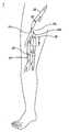
- the venous systemcontains numerous one-way valves for directing blood flow back to the heart such as those valves 20 located in the vein 22 shown in FIG. 1 .
- the arrow leading out the top of the veinrepresents the antegrade flow of blood back to the heart.
- Venous valvesare usually bicuspid valves, with each cusp 24 forming a sack or reservoir 26 for blood which, under retrograde blood pressure, forces the free surfaces of the cusps together to prevent retrograde flow of the blood and allows only antegrade blood flow to the heart.
- Competent venous valvesprevent retrograde flow as blood is pushed forward through the vein lumen and back to the heart.
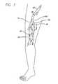
- FIG. 2A cross-sectional perspective view of a dilated vein with an incompetent valve 28 taken along lines 2 - 2 of FIG. 1 is illustrated in FIG. 2 .
- valve cusps 24can experience some separation at the commissure due to the thinning and stretching of the vein wall at the cusps.
- Two venous 10 conditions which often result from valve failureare varicose veins and more symptomatic chronic venous insufficiency.
- the varicose vein conditionincludes dilation and tortuosity of the superficial veins of the lower limbs, resulting in unsightly discoloration, pain, swelling, and possibly ulceration.
- Varicose veinsoften involve incompetence of one or more venous valves, which allow reflux of blood within the superficial system. This can also worsen deep venous reflux and perforator reflux.
- Current treatments of vein insufficiencyinclude surgical procedures such as vein stripping, ligation, and occasionally, vein-segment transplant.
- Chronic venous insufficiencyinvolves an aggravated condition of varicose veins which may be caused by degenerative weakness in the vein valve segment, or by hydrodynamic forces acting on the tissues of the body, such as the legs, ankles, and feet.
- the hydrostatic pressureincreases on the next venous valves down, causing those veins to dilate.
- more venous valveswill eventually fail.
- the effective height of the column of blood above the feet and anklesgrows, and the weight and hydrostatic pressure exerted on the tissues of the ankle and foot increases.
- ulcerations of the anklebegin to form, which start deep and eventually come to the surface.
- Varicose veinscan be treated by intra-luminal Ligation.
- ligationor “intra-luminal ligation” comprises the occlusion, collapse, or closure of a lumen or hollow anatomical structure by the application of energy from within the lumen or structure.
- ligationor “intraluminal ligation” includes electro-ligation. An electrode device is introduced into the lumen and RF energy is applied to the wall by the electrode device to ligate or close off the lumen.
- the ligation treatmentis often commenced at the sapheno-femoral junction (SFJ) in order to close down the tributaries in the region and prevent the subsequent development of alternate flow paths which can lead to recurrent varicosities. Improper placement of the catheter past the SFJ and into the femoral vein could cause heating of the blood or vein walls in the deep venous system.
- SFJsapheno-femoral junction
- the location of a catheter within the body of a patientis routinely detected by the use of imaging equipment, such as ultrasound or X-ray equipment.
- the imaging equipmentallows the operator to place the electrode catheter near the SFJ.
- Such a procedurerequires transportation of the patient to an ultrasound or X-ray facility or, conversely, transportation of the ultrasound or X-ray equipment to the patient.
- imaging equipmentis bulky, requires an additional person to operate the equipment, and can be time consuming to use. This can be both inconvenient and costly. Physiological factors can also interfere with the resolution of the system and prevent the acquisition of a clean image.
- scheduling difficultiesmay arise based on the availability of the ultrasound facility or equipment, thereby delaying the minimally invasive treatment which would benefit the patient.
- the present inventionis directed to a method of positioning a catheter proximate to a junction in a hollow anatomical structure, the method comprising the steps of introducing a catheter into the hollow anatomical structure; identifying the junction in the hollow anatomical structure based on feedback from the catheter without imaging the hollow anatomical structure during the treatment; positioning the working end of the catheter proximate to the location identified in the step of identifying.
- the feedback from the catheteris light emitted from the catheter, wherein the emitted light is visible externally from the patient, and the light disappears as the catheter goes deeper into the anatomy as it nears or enters the anatomical junction.
- the feedback from the catheteris magnetically activated.
- the magnetic feedback systemis capable of detecting the orientation of the working end of the catheter, such as by utilizing horizontally-orientated and vertically-orientated magnetic fields generated by a hand-held instrument placed adjacent the patient, the location of the sapheno-femoral junction can be determined from the change in orientation of the working end of the catheter as it dives toward the sapheno-femoral junction.
- the feedback from the catheteris a radio-frequency signal from a transmitter located at the working end of the catheter. The feedback can also be from an ultrasound transducer or transponder.
- the feedback from the catheteris based on a characteristic measured at the working end of the catheter to determine the flow rate in the vein.
- the flow rateshould increase going from the saphenous vein to the femoral vein at the sapheno-femoral junction. Where the flow rate is determined while the vein is undergoing compression, the compressed saphenous vein would have zero flow (or near zero flow) while the femoral vein would still exhibit some flow since it is deeper in the leg.
- the working end of the cathetercan be momentarily energized, and the subsequent temperature decay can be used to determine the flow rate.
- the feedback from the catheteris mechanically based on a hook-shaped guide wire which engages the ostium of the sapheno-femoral junction.
- FIG. 1shows a cross-sectional view of a vein having competent valves and having a dilated section with incompetent venous valves in a lower limb which are to be treated in accordance with the present invention
- FIG. 2shows a representative view of a venous section with an incompetent valve from FIG. 1 taken along lines 2 - 2 which is to be treated in accordance with the present invention
- FIG. 3is a cross-sectional view of a vein and a fiber optic device introduced as delivered to the sapheno-femoral junction;
- FIG. 4is a diagram of an energy application system that may be used in conjunction with the method of the present invention, depicting a partial cutaway view of the first embodiment of the catheter showing both the working end and the connecting end with an RF generator and a microprocessor connected at the connection end;
- FIG. 5is a cross-sectional view of the working end of an embodiment of a catheter having a fiber optic device at the working end of the catheter in accordance with the invention
- FIG. 5 ais an end-on view of the non-expanded embodiment of FIG. 5 ;
- FIG. 6is a cross-sectional view of the working end of an embodiment of a hook-shaped guide wire in accordance with the invention.
- FIG. 6 ais an end-on view of the expanded embodiment of FIG. 6 ;
- FIG. 7is a cross-sectional view of the working end of another embodiment of a hook-shaped guide wire in accordance with the invention.
- FIG. 8is a cross-sectional view of the working end of an embodiment of a catheter having a hook-shaped tip in accordance with the invention.
- FIG. 9is a cross-sectional view showing an expandable energy application device within a hollow anatomical structure.
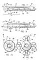
- FIG. 10is a side view of the non-expanded tip of an energy application device.
- FIG. 11is a perspective view of an expanded tip of an energy application device.
- FIG. 12is a cross-sectional view of a non-expanded tip of an energy application device.
- the inventionis directed toward the positioning of a catheter to a treatment site for the intravenous treatment of veins.
- like reference numeralswill designate similar elements in the various embodiments of the present invention to be discussed.
- the term “working end”will refer to the direction toward the treatment site in the patient, and the term “connecting end” will refer to the direction away from the treatment site in the patient.
- RF energyis discussed, it is to be understood that other forms of energy such as microwaves, ultrasound, direct current, circulating heated fluid, radiant light, and lasers can be used, and that the thermal energy generated from a resistive coil or curie point element may be used as well.
- the inventionwill be described in relation to the treatment of the venous system of the lower limbs, such as the saphenous vein in the leg. It is to be understood, however, that the invention is not limited thereto and may be employed intraluminally to treat veins in other areas of the body.
- a catheter 30 carrying an electrode device 32is introduced into the vein and placed near the sapheno-femoral junction (SFJ).
- the electrode cathetercan be placed intraluminally near the sapheno-femoral junction (SFJ).
- the tissue surrounding the treatment sitecan be hi compressed via an elastic compression wrap, inflatable cuff, or a tumescent anesthesia technique.
- the tumescent anesthesia techniqueis described in copending patent application Ser. No. 09/322,326, which is hereby incorporated by reference in its entirety.
- the tumescent anesthesia techniqueinvolves a dilute anesthetic solution which is injected into the tissue surrounding the vein to be treated.
- the expandable electrode device which has been introduced into the patientis then expanded into non-penetrating apposition with the venous tissue after compression of the vein.
- the electrodeis then activated, and energy such as high frequency RF energy is applied from the expandable electrode device to the venous tissue until the vein durably assumes dimensions less than or equal to the compressed dimensions.
- energysuch as high frequency RF energy is applied from the expandable electrode device to the venous tissue until the vein durably assumes dimensions less than or equal to the compressed dimensions.
- the catheterpulled back to ligate or close off an extensive section of the saphenous vein (GSV).
- GSVsaphenous vein
- One embodiment of the catheter 30includes the expandable electrode device 56 that moves in and out of the outer sheath by way of the distal orifice 38 , although in other embodiments the device 56 may expand from and contract into the catheter 30 at other locations.
- the expandable electrode device 56includes a plurality of electrodes 58 which can be expanded by moving the outer sheath 36 relative to the electrodes.
- An actuator 76controls the extension of the electrode device 56 through the distal orifice 38 .
- the actuatormay take the form of a lever 78 , switch, threaded control knob, or other suitable mechanism, and is preferably one that can provide fine control over the movement of the outer sheath 36 or the inner sheath 60 , as the case may be.
- the actuatorinterfaces with the outer sheath to move it back and forth relative to the inner sheath. In another embodiment the actuator interfaces with the inner sheath to move it back and forth relative to the outer sheath.
- Operation of the actuator 76causes relative movement of the outer sheath such that the outer sheath no longer restrains the electrodes, and the primary electrodes 58 are moved by the primary leads move outward relative to the axis defined by the outer sheath, while the central secondary electrode 59 remains substantially linear along the axis defined by the outer sheath.
- the primary leadscontinue to move outward until the electrodes are placed in apposition with the vein wall and the outward movement of the primary leads is impeded.
- the primary electrodes 58contact the vein wall along a generally circumferential area or band of the vein wall.
- the RF generator 50is activated to provide suitable RF energy to produce a thermal effect which causes the venous tissue to shrink, reducing the diameter of the vein.
- the primary lead electrodesare pressed closer together by the shrinking vein wall and assume a reduced profile shape which is sufficiently small so that the vein is effectively ligated.
- one method of determining the location of the sapheno-femoral junctioninvolves the use of a fiber optic device 35 .
- the fiber optic device 35is introduced into the saphenous vein (GSV) through an incision, and directed toward the sapheno-femoral junction (SFJ).
- the fiber optic device 35is connected to a light source.
- the light emitted from the fiber optic device 35is visible externally from the patient, thereby providing visual feedback to allow the physician to monitor the progress and location of the fiber optic device 35 in the patient.
- Fiber optic devicesoften emit light forward in a directional manner.
- the fiber optic device 35can be constructed to emit light in a radial fashion to facilitate external visualization.
- the saphenous vein (GSV)travels past the deep fascia as it approaches the sapheno-femoral junction (SFJ).
- the point where the light from the fiberoptic device 35 dims or is no longer visible externally from the patientis marked to identify the location of the sapheno-femoral junction (SFJ) as an anatomical landmark.
- the length of the fiber optic device 35 that has been introduced into the patientis recorded.
- the catheter 30When the fiber optic device 35 is removed from the patient, the catheter 30 is introduced through the same incision for the same length as the fiber optic device that was introduced into the patient. Having traveled the same distance as the fiber optic device 35 , the electrode device at the working end of 20 the catheter 30 should be proximate to the sapheno-femoral junction (SFJ).
- SFJsapheno-femoral junction
- the electrode deviceis activated to begin the ligation procedure.
- Suitable electrode catheters and vein ligation techniquesare described in co-pending U.S. patent application Ser. Nos. 08/927,251 and 09/267,127, which are hereby incorporated by reference.
- the catheter 30includes a lumen which runs substantially along the axis of the inner member before terminating at the guide wire port 48 of the handle 44 .
- the lumentravels through the central electrode 59 .
- a guide wirecan be introduced through the lumen of the catheter for use in guiding the catheter to the desired treatment site.
- the fiber optic device 35can be utilized as a guide wire, thereby eliminating the need to remove the fiber optic device 35 before the introduction of the catheter 30 .
- the cathetercan travel over the fiber optic device to arrive at the desired sapheno-femoral junction (SFJ).
- the light-emitting portion of the fiber optic devicecan be configured to emit light in a radial non-directional manner.
- a fiber optic deviceis combined as part of the working end of the catheter, and a conventional guide wire can be introduced through the guide wire port and lumen.
- FIG. 5is similar to FIG. 4 , except that the central electrode 59 has been replaced by an integrated fiber optic device 85 which emits light in a radial fashion. While the integrated fiber optic device 85 does not include a separate lumen for a guide wire, it is to be understood that a lumen may be formed through the fiber optic device 85 . As previously discussed, once the fiber optic device travels past the deep fascia layer to near the sapheno-femoral junction (SFJ), the emitted light will dim or no longer be visible externally from the patient. This configuration avoids the need to remove the fiber optic device prior to the introduction of the electrode catheter. This configuration also allows for a more direct determination of the position of the catheter relative to the sapheno-femoral junction (SFJ).
- SFJsapheno-femoral junction
- ultrasoundcan be used to identify the location of the patient's sapheno-femoral junction (SFJ) prior to the treatment procedure of ligating the vein, but ultrasound imaging need not be used during the procedure.
- the SFJis identified by ultrasound prior to the procedure, and the location of the SFJ is externally marked on the skin of the patient.
- the working end of the catheteris positioned at the externally marked location based on the feedback from the signal detection mechanism in the catheter.
- an electromagnetic position sensing systemsuch as that described in U.S. Patent No. 5,645,065, can be utilized.
- signal detection and feedback mechanismssuch as ultrasonic transducers or transponders, and radio-frequency transmitters can be used at the working end of the catheter.
- the signal detection or feedback mechanismssuch as an ultrasonic transducer/transponder or radio-frequency transmitter, can also be used in a separate wire over which the catheter is advanced or introduced.
- the feedback mechanismcan be in the form of a separate wire inserted into a lumen of the catheter, or a sensor integrated into the catheter.
- the working end of the catheteris positioned at the externally marked location based on the feedback from the signal detection mechanism.
- a magnetic position sensing systemis additionally capable of detecting the change in orientation of the working end of the catheter as it dives toward the sapheno-femoral junction (SFJ) to indicate the placement and location of the catheter.
- the cathetercan transmit or receive a signal based on a magnetic field.
- a magnet located at the working end of the catheterprovides horizontally and vertically generated feedback to the sensing system to indicate position and orientation.
- An instrument external to the patientmonitors the orientation of the working end of the catheter based on the feedback from the magnet.
- the magnetcan be integral to the catheter, or part of a separate wire over which the catheter is introduced or advanced.
- the magnetcan be either passive (static) or active.
- the cathetercan receive a signal based on a magnetic field generated outside the patient.
- the catheter 30includes an expandable energy application device 56 which in this embodiment, comprises an array of electrodes 58 , an outer sheath 36 having a distal orifice 38 at its working end 40 .
- the connector end 42 of the outer sheathis attached to a handle 44 that includes electrical connector 46 .
- the handleadditionally includes a guide wire port 48 .
- the connector 46is for interfacing with a power source, typically an RF generator 50 , and a microprocessor controller 52 .
- the microprocessor controllerreceives data from a sensor 54 , such as a thermocouple or impedance sensor, at an intraluminal venous treatment site.
- FIG. 4illustrates a plurality of electrodes 58 surrounding a single central electrode 59 , different electrode configurations may be used.
- the sensor 54also provides data signals for determining the flow rate from the working end of the catheter.
- the sensor 54can be a thermocouple to measure the temperature decay after momentarily energizing the electrode to cause a small heating effect.
- Another embodimentwould be to measure the power required to maintain the electrode at a constant temperature. The required power to maintain a constant temperature would increase as the flow increases.
- the temperature rise for a fixed input powercan be measured. The temperature rise for a fixed input power will decrease as flow increases.
- the flow rateshould increase going from the saphenous vein to the femoral vein at the sapheno-femoral junction.
- the compressed saphenous veinwould have zero to near zero flow while the femoral vein would still exhibit some flow since it is deeper.
- Another method of measuring flow rateemploys a flow wire which can be used prior to the introduction of the catheter, or through the central lumen of the catheter, to determine the flow rate in the vein.
- the sensor 54can be an impedance sensor to measure the impedance of the surrounding anatomy at the working end of the catheter. Impedance measurements can also be used to direct and confirm the specific placement of the catheter at the ostium of a vessel such as the SFJ. The impedance will be low when the electrodes are in the blood stream. A higher impedance value indicates electrode contact with the vein wall.
- FIG. 6illustrates a catheter where a hook-shaped guide wire 87 is placed through the central lumen 80 .
- the hook-shaped guide wire 87can have a hook-shaped tip, or be formed from a shape-memory metal so that the tip would become hook-shaped at a specific temperature, or be fabricated with a flexible tip that could be shaped into a hook pulling on a wire attached eccentrically to the flexible tip.
- the hook-shaped tipwould mechanically engage the ostium of the sapheno-femoral junction (SFJ).
- SFJsapheno-femoral junction
- the cathetercan be positioned relative to the SFJ.
- the length of the catheter to be introducedwould be determined by the length of the guide wire remaining in the target vessel once the guide wire is engaged with the SFJ.
- a mechanical stopis located proximal to the hook-shaped tip of the guide wire.
- the mechanical stopcan take the form of a sphere, raised bump, or sleeve. As the catheter is introduced over the guide wire, the tip of the catheter encounters the mechanical stop which prevents further insertion over the guide wire. The distance from the mechanical stop to the hook feature positions the catheter tip the desired distance from the SFJ.
- the catheteritself includes a hook-shaped tip.
- the hook-shaped tipcan be made integral to the catheter.
- the tipcan be preformed into a hook shape, or fabricated from a shape memory metal so that the tip would assume a hook shape at a specific temperature, or be fabricated from a flexible material that could be shaped into a hook pulling on a wire attached eccentrically to the flexible tip.
- the handle of the catheterwould include a device to cause the heating of the shape memory metal embodiment.
- the handlewould include a mechanism for pulling on a tip-deflecting wire attached at the catheter tip.
- the hook-shaped tip of the catheterwould mechanically engage the ostium of the SFJ and position the catheter electrodes relative to the SFJ before the initial activation of the electrodes. Prior to pulling back on the catheter to collapse a length of the vein or vessel, the hook-shaped tip is straightened to release the catheter from the ostium of the SFJ.
- the cathetercan include one or more sensors, such as thermocouples, mounted in place on an electrode so that the sensor is substantially flush with the exposed surface of the electrode.
- sensorsare shown in a raised position in the drawings for clarity of illustration only. The sensors can be used in conjunction with the fiber optic device or the hook-shaped guide wire to properly position the catheter at the SFJ.
Landscapes
- Health & Medical Sciences (AREA)
- Surgery (AREA)
- Life Sciences & Earth Sciences (AREA)
- Engineering & Computer Science (AREA)
- Heart & Thoracic Surgery (AREA)
- Animal Behavior & Ethology (AREA)
- Otolaryngology (AREA)
- Plasma & Fusion (AREA)
- Physics & Mathematics (AREA)
- Biomedical Technology (AREA)
- Cardiology (AREA)
- Medical Informatics (AREA)
- Molecular Biology (AREA)
- Nuclear Medicine, Radiotherapy & Molecular Imaging (AREA)
- General Health & Medical Sciences (AREA)
- Public Health (AREA)
- Veterinary Medicine (AREA)
- Surgical Instruments (AREA)
- Media Introduction/Drainage Providing Device (AREA)
- Magnetic Resonance Imaging Apparatus (AREA)
- Radiation-Therapy Devices (AREA)
- Ultra Sonic Daignosis Equipment (AREA)
Abstract
Description
Claims (39)
Priority Applications (5)
| Application Number | Priority Date | Filing Date | Title |
|---|---|---|---|
| US09/825,741US7789876B2 (en) | 2000-08-14 | 2001-04-03 | Method and apparatus for positioning a catheter relative to an anatomical junction |
| DE60122071TDE60122071T2 (en) | 2000-08-14 | 2001-08-14 | Device for relative positioning of a catheter to an anatomical connection |
| AT01306926TATE335440T1 (en) | 2000-08-14 | 2001-08-14 | DEVICE FOR POSITIONING A CATHETER RELATIVELY TO AN ANATOMICAL CONNECTION |
| EP01306926AEP1181895B1 (en) | 2000-08-14 | 2001-08-14 | Apparatus for positioning a catheter relative to an anatomical junction |
| US12/875,951US20110160813A1 (en) | 2000-08-14 | 2010-09-03 | Method and apparatus for positioning a catheter relative to an anatomical junction |
Applications Claiming Priority (2)
| Application Number | Priority Date | Filing Date | Title |
|---|---|---|---|
| US63830700A | 2000-08-14 | 2000-08-14 | |
| US09/825,741US7789876B2 (en) | 2000-08-14 | 2001-04-03 | Method and apparatus for positioning a catheter relative to an anatomical junction |
Related Parent Applications (1)
| Application Number | Title | Priority Date | Filing Date |
|---|---|---|---|
| US63830700AContinuation | 2000-08-14 | 2000-08-14 |
Related Child Applications (1)
| Application Number | Title | Priority Date | Filing Date |
|---|---|---|---|
| US12/875,951ContinuationUS20110160813A1 (en) | 2000-08-14 | 2010-09-03 | Method and apparatus for positioning a catheter relative to an anatomical junction |
Publications (2)
| Publication Number | Publication Date |
|---|---|
| US20020068866A1 US20020068866A1 (en) | 2002-06-06 |
| US7789876B2true US7789876B2 (en) | 2010-09-07 |
Family
ID=27093055
Family Applications (2)
| Application Number | Title | Priority Date | Filing Date |
|---|---|---|---|
| US09/825,741Expired - Fee RelatedUS7789876B2 (en) | 2000-08-14 | 2001-04-03 | Method and apparatus for positioning a catheter relative to an anatomical junction |
| US12/875,951AbandonedUS20110160813A1 (en) | 2000-08-14 | 2010-09-03 | Method and apparatus for positioning a catheter relative to an anatomical junction |
Family Applications After (1)
| Application Number | Title | Priority Date | Filing Date |
|---|---|---|---|
| US12/875,951AbandonedUS20110160813A1 (en) | 2000-08-14 | 2010-09-03 | Method and apparatus for positioning a catheter relative to an anatomical junction |
Country Status (4)
| Country | Link |
|---|---|
| US (2) | US7789876B2 (en) |
| EP (1) | EP1181895B1 (en) |
| AT (1) | ATE335440T1 (en) |
| DE (1) | DE60122071T2 (en) |
Cited By (86)
| Publication number | Priority date | Publication date | Assignee | Title |
|---|---|---|---|---|
| US20070244371A1 (en)* | 2006-04-04 | 2007-10-18 | Nguyen Hoa D | Phlebectomy illumination device and methods |
| US20100280328A1 (en)* | 2009-05-01 | 2010-11-04 | Tyco Healthcare Group, Lp | Methods and systems for illumination during phlebectomy procedures |
| US8880185B2 (en) | 2010-06-11 | 2014-11-04 | Boston Scientific Scimed, Inc. | Renal denervation and stimulation employing wireless vascular energy transfer arrangement |
| US8939970B2 (en) | 2004-09-10 | 2015-01-27 | Vessix Vascular, Inc. | Tuned RF energy and electrical tissue characterization for selective treatment of target tissues |
| US8945142B2 (en) | 2008-08-27 | 2015-02-03 | Cook Medical Technologies Llc | Delivery system for implanting nasal ventilation tube |
| US8951251B2 (en) | 2011-11-08 | 2015-02-10 | Boston Scientific Scimed, Inc. | Ostial renal nerve ablation |
| US8974451B2 (en) | 2010-10-25 | 2015-03-10 | Boston Scientific Scimed, Inc. | Renal nerve ablation using conductive fluid jet and RF energy |
| US9023034B2 (en) | 2010-11-22 | 2015-05-05 | Boston Scientific Scimed, Inc. | Renal ablation electrode with force-activatable conduction apparatus |
| US9028485B2 (en) | 2010-11-15 | 2015-05-12 | Boston Scientific Scimed, Inc. | Self-expanding cooling electrode for renal nerve ablation |
| US9028472B2 (en) | 2011-12-23 | 2015-05-12 | Vessix Vascular, Inc. | Methods and apparatuses for remodeling tissue of or adjacent to a body passage |
| US9050106B2 (en) | 2011-12-29 | 2015-06-09 | Boston Scientific Scimed, Inc. | Off-wall electrode device and methods for nerve modulation |
| US9060761B2 (en) | 2010-11-18 | 2015-06-23 | Boston Scientific Scime, Inc. | Catheter-focused magnetic field induced renal nerve ablation |
| US9079000B2 (en) | 2011-10-18 | 2015-07-14 | Boston Scientific Scimed, Inc. | Integrated crossing balloon catheter |
| US9084609B2 (en) | 2010-07-30 | 2015-07-21 | Boston Scientific Scime, Inc. | Spiral balloon catheter for renal nerve ablation |
| US9089350B2 (en) | 2010-11-16 | 2015-07-28 | Boston Scientific Scimed, Inc. | Renal denervation catheter with RF electrode and integral contrast dye injection arrangement |
| US9119600B2 (en) | 2011-11-15 | 2015-09-01 | Boston Scientific Scimed, Inc. | Device and methods for renal nerve modulation monitoring |
| US9119632B2 (en) | 2011-11-21 | 2015-09-01 | Boston Scientific Scimed, Inc. | Deflectable renal nerve ablation catheter |
| US9125667B2 (en) | 2004-09-10 | 2015-09-08 | Vessix Vascular, Inc. | System for inducing desirable temperature effects on body tissue |
| US9125666B2 (en) | 2003-09-12 | 2015-09-08 | Vessix Vascular, Inc. | Selectable eccentric remodeling and/or ablation of atherosclerotic material |
| US9155589B2 (en) | 2010-07-30 | 2015-10-13 | Boston Scientific Scimed, Inc. | Sequential activation RF electrode set for renal nerve ablation |
| US9162046B2 (en) | 2011-10-18 | 2015-10-20 | Boston Scientific Scimed, Inc. | Deflectable medical devices |
| US9173696B2 (en) | 2012-09-17 | 2015-11-03 | Boston Scientific Scimed, Inc. | Self-positioning electrode system and method for renal nerve modulation |
| US9186210B2 (en) | 2011-10-10 | 2015-11-17 | Boston Scientific Scimed, Inc. | Medical devices including ablation electrodes |
| US9186209B2 (en) | 2011-07-22 | 2015-11-17 | Boston Scientific Scimed, Inc. | Nerve modulation system having helical guide |
| US9192435B2 (en) | 2010-11-22 | 2015-11-24 | Boston Scientific Scimed, Inc. | Renal denervation catheter with cooled RF electrode |
| US9192790B2 (en) | 2010-04-14 | 2015-11-24 | Boston Scientific Scimed, Inc. | Focused ultrasonic renal denervation |
| US9220561B2 (en) | 2011-01-19 | 2015-12-29 | Boston Scientific Scimed, Inc. | Guide-compatible large-electrode catheter for renal nerve ablation with reduced arterial injury |
| US9220558B2 (en) | 2010-10-27 | 2015-12-29 | Boston Scientific Scimed, Inc. | RF renal denervation catheter with multiple independent electrodes |
| US9265969B2 (en) | 2011-12-21 | 2016-02-23 | Cardiac Pacemakers, Inc. | Methods for modulating cell function |
| US9277955B2 (en) | 2010-04-09 | 2016-03-08 | Vessix Vascular, Inc. | Power generating and control apparatus for the treatment of tissue |
| US9297845B2 (en) | 2013-03-15 | 2016-03-29 | Boston Scientific Scimed, Inc. | Medical devices and methods for treatment of hypertension that utilize impedance compensation |
| US9327100B2 (en) | 2008-11-14 | 2016-05-03 | Vessix Vascular, Inc. | Selective drug delivery in a lumen |
| US9326751B2 (en) | 2010-11-17 | 2016-05-03 | Boston Scientific Scimed, Inc. | Catheter guidance of external energy for renal denervation |
| US9358365B2 (en) | 2010-07-30 | 2016-06-07 | Boston Scientific Scimed, Inc. | Precision electrode movement control for renal nerve ablation |
| US9364284B2 (en) | 2011-10-12 | 2016-06-14 | Boston Scientific Scimed, Inc. | Method of making an off-wall spacer cage |
| US9408661B2 (en) | 2010-07-30 | 2016-08-09 | Patrick A. Haverkost | RF electrodes on multiple flexible wires for renal nerve ablation |
| US9420955B2 (en) | 2011-10-11 | 2016-08-23 | Boston Scientific Scimed, Inc. | Intravascular temperature monitoring system and method |
| US9433760B2 (en) | 2011-12-28 | 2016-09-06 | Boston Scientific Scimed, Inc. | Device and methods for nerve modulation using a novel ablation catheter with polymeric ablative elements |
| US9463062B2 (en) | 2010-07-30 | 2016-10-11 | Boston Scientific Scimed, Inc. | Cooled conductive balloon RF catheter for renal nerve ablation |
| US9486270B2 (en) | 2002-04-08 | 2016-11-08 | Medtronic Ardian Luxembourg S.A.R.L. | Methods and apparatus for bilateral renal neuromodulation |
| US9486355B2 (en) | 2005-05-03 | 2016-11-08 | Vessix Vascular, Inc. | Selective accumulation of energy with or without knowledge of tissue topography |
| US9579030B2 (en) | 2011-07-20 | 2017-02-28 | Boston Scientific Scimed, Inc. | Percutaneous devices and methods to visualize, target and ablate nerves |
| US9649156B2 (en) | 2010-12-15 | 2017-05-16 | Boston Scientific Scimed, Inc. | Bipolar off-wall electrode device for renal nerve ablation |
| US9668811B2 (en) | 2010-11-16 | 2017-06-06 | Boston Scientific Scimed, Inc. | Minimally invasive access for renal nerve ablation |
| US9687166B2 (en) | 2013-10-14 | 2017-06-27 | Boston Scientific Scimed, Inc. | High resolution cardiac mapping electrode array catheter |
| US9693821B2 (en) | 2013-03-11 | 2017-07-04 | Boston Scientific Scimed, Inc. | Medical devices for modulating nerves |
| US9707036B2 (en) | 2013-06-25 | 2017-07-18 | Boston Scientific Scimed, Inc. | Devices and methods for nerve modulation using localized indifferent electrodes |
| US9713730B2 (en) | 2004-09-10 | 2017-07-25 | Boston Scientific Scimed, Inc. | Apparatus and method for treatment of in-stent restenosis |
| US9770606B2 (en) | 2013-10-15 | 2017-09-26 | Boston Scientific Scimed, Inc. | Ultrasound ablation catheter with cooling infusion and centering basket |
| US9808300B2 (en) | 2006-05-02 | 2017-11-07 | Boston Scientific Scimed, Inc. | Control of arterial smooth muscle tone |
| US9808311B2 (en) | 2013-03-13 | 2017-11-07 | Boston Scientific Scimed, Inc. | Deflectable medical devices |
| US9827039B2 (en) | 2013-03-15 | 2017-11-28 | Boston Scientific Scimed, Inc. | Methods and apparatuses for remodeling tissue of or adjacent to a body passage |
| US9833283B2 (en) | 2013-07-01 | 2017-12-05 | Boston Scientific Scimed, Inc. | Medical devices for renal nerve ablation |
| US9895194B2 (en) | 2013-09-04 | 2018-02-20 | Boston Scientific Scimed, Inc. | Radio frequency (RF) balloon catheter having flushing and cooling capability |
| US9907609B2 (en) | 2014-02-04 | 2018-03-06 | Boston Scientific Scimed, Inc. | Alternative placement of thermal sensors on bipolar electrode |
| US9925001B2 (en) | 2013-07-19 | 2018-03-27 | Boston Scientific Scimed, Inc. | Spiral bipolar electrode renal denervation balloon |
| US9943365B2 (en) | 2013-06-21 | 2018-04-17 | Boston Scientific Scimed, Inc. | Renal denervation balloon catheter with ride along electrode support |
| US9956033B2 (en) | 2013-03-11 | 2018-05-01 | Boston Scientific Scimed, Inc. | Medical devices for modulating nerves |
| US9956384B2 (en) | 2014-01-24 | 2018-05-01 | Cook Medical Technologies Llc | Articulating balloon catheter and method for using the same |
| US9962223B2 (en) | 2013-10-15 | 2018-05-08 | Boston Scientific Scimed, Inc. | Medical device balloon |
| US9974607B2 (en) | 2006-10-18 | 2018-05-22 | Vessix Vascular, Inc. | Inducing desirable temperature effects on body tissue |
| US10022182B2 (en) | 2013-06-21 | 2018-07-17 | Boston Scientific Scimed, Inc. | Medical devices for renal nerve ablation having rotatable shafts |
| US10085799B2 (en) | 2011-10-11 | 2018-10-02 | Boston Scientific Scimed, Inc. | Off-wall electrode device and methods for nerve modulation |
| US10265122B2 (en) | 2013-03-15 | 2019-04-23 | Boston Scientific Scimed, Inc. | Nerve ablation devices and related methods of use |
| US10271898B2 (en) | 2013-10-25 | 2019-04-30 | Boston Scientific Scimed, Inc. | Embedded thermocouple in denervation flex circuit |
| US10293190B2 (en) | 2002-04-08 | 2019-05-21 | Medtronic Ardian Luxembourg S.A.R.L. | Thermally-induced renal neuromodulation and associated systems and methods |
| US10321946B2 (en) | 2012-08-24 | 2019-06-18 | Boston Scientific Scimed, Inc. | Renal nerve modulation devices with weeping RF ablation balloons |
| US10335280B2 (en) | 2000-01-19 | 2019-07-02 | Medtronic, Inc. | Method for ablating target tissue of a patient |
| US10342609B2 (en) | 2013-07-22 | 2019-07-09 | Boston Scientific Scimed, Inc. | Medical devices for renal nerve ablation |
| US10398464B2 (en) | 2012-09-21 | 2019-09-03 | Boston Scientific Scimed, Inc. | System for nerve modulation and innocuous thermal gradient nerve block |
| US10413357B2 (en) | 2013-07-11 | 2019-09-17 | Boston Scientific Scimed, Inc. | Medical device with stretchable electrode assemblies |
| US10543037B2 (en) | 2013-03-15 | 2020-01-28 | Medtronic Ardian Luxembourg S.A.R.L. | Controlled neuromodulation systems and methods of use |
| US10549127B2 (en) | 2012-09-21 | 2020-02-04 | Boston Scientific Scimed, Inc. | Self-cooling ultrasound ablation catheter |
| US10589130B2 (en) | 2006-05-25 | 2020-03-17 | Medtronic, Inc. | Methods of using high intensity focused ultrasound to form an ablated tissue area containing a plurality of lesions |
| US10660698B2 (en) | 2013-07-11 | 2020-05-26 | Boston Scientific Scimed, Inc. | Devices and methods for nerve modulation |
| US10660703B2 (en) | 2012-05-08 | 2020-05-26 | Boston Scientific Scimed, Inc. | Renal nerve modulation devices |
| US10695124B2 (en) | 2013-07-22 | 2020-06-30 | Boston Scientific Scimed, Inc. | Renal nerve ablation catheter having twist balloon |
| US10722300B2 (en) | 2013-08-22 | 2020-07-28 | Boston Scientific Scimed, Inc. | Flexible circuit having improved adhesion to a renal nerve modulation balloon |
| US10835305B2 (en) | 2012-10-10 | 2020-11-17 | Boston Scientific Scimed, Inc. | Renal nerve modulation devices and methods |
| US10945786B2 (en) | 2013-10-18 | 2021-03-16 | Boston Scientific Scimed, Inc. | Balloon catheters with flexible conducting wires and related methods of use and manufacture |
| US10952790B2 (en) | 2013-09-13 | 2021-03-23 | Boston Scientific Scimed, Inc. | Ablation balloon with vapor deposited cover layer |
| US11000679B2 (en) | 2014-02-04 | 2021-05-11 | Boston Scientific Scimed, Inc. | Balloon protection and rewrapping devices and related methods of use |
| US11202671B2 (en) | 2014-01-06 | 2021-12-21 | Boston Scientific Scimed, Inc. | Tear resistant flex circuit assembly |
| US11246654B2 (en) | 2013-10-14 | 2022-02-15 | Boston Scientific Scimed, Inc. | Flexible renal nerve ablation devices and related methods of use and manufacture |
| US11497507B2 (en) | 2017-02-19 | 2022-11-15 | Orpheus Ventures, Llc | Systems and methods for closing portions of body tissue |
| US11877784B2 (en) | 2014-03-26 | 2024-01-23 | Venclose, Inc. | Venous disease treatment |
Families Citing this family (62)
| Publication number | Priority date | Publication date | Assignee | Title |
|---|---|---|---|---|
| AU6146798A (en)* | 1997-03-04 | 1998-09-22 | Vnus Medical Technologies, Inc. | Method and apparatus for treating venous insufficiency using directionally applied energy |
| US8252034B2 (en) | 2001-01-05 | 2012-08-28 | Chambers Jeffrey W | Method of positioning a stent using rods |
| US7992573B2 (en)* | 2001-06-19 | 2011-08-09 | The Trustees Of The University Of Pennsylvania | Optically guided system for precise placement of a medical catheter in a patient |
| US7623903B2 (en)* | 2002-05-17 | 2009-11-24 | Wacker Frank K | Double contrast technique for MRI-guided vascular interventions |
| DE10256007A1 (en)* | 2002-11-30 | 2004-06-09 | Philips Intellectual Property & Standards Gmbh | A catheter assembly |
| WO2006031541A1 (en)* | 2004-09-09 | 2006-03-23 | Vnus Medical Technologies, Inc. | Methods and apparatus for treatment of hollow anatomical structures |
| US7274847B2 (en)* | 2004-11-16 | 2007-09-25 | Biotex, Inc. | Light diffusing tip |
| US20060116572A1 (en)* | 2004-12-01 | 2006-06-01 | Case Brian C | Sensing delivery system for intraluminal medical devices |
| EP2438877B1 (en) | 2005-03-28 | 2016-02-17 | Vessix Vascular, Inc. | Intraluminal electrical tissue characterization and tuned RF energy for selective treatment of atheroma and other target tissues |
| US20090118612A1 (en) | 2005-05-06 | 2009-05-07 | Sorin Grunwald | Apparatus and Method for Vascular Access |
| US20070016069A1 (en)* | 2005-05-06 | 2007-01-18 | Sorin Grunwald | Ultrasound sensor |
| US20070167745A1 (en)* | 2005-12-29 | 2007-07-19 | Cook Incorporated | Methods for delivering medical devices to a target implant site within a body vessel |
| WO2007100731A2 (en)* | 2006-02-24 | 2007-09-07 | Nanovibronix Inc. | System and method for surface acoustic wave treatment of medical devices |
| EP2020965B1 (en)* | 2006-05-04 | 2017-04-19 | Cook Medical Technologies LLC | Self-orienting delivery system |
| AU2007216674A1 (en)* | 2006-09-21 | 2008-04-10 | Cathrx Ltd | A catheter assembly |
| US20130046172A1 (en)* | 2007-03-14 | 2013-02-21 | Kathryn A. McKenzie Waitzman | Methods and systems for locating a feeding tube inside of a person |
| EP2120839A2 (en)* | 2007-03-14 | 2009-11-25 | Kathryn A. Mckenzie Waitzman | Methods and systems for locating a feeding tube inside of a patient |
| US8496653B2 (en) | 2007-04-23 | 2013-07-30 | Boston Scientific Scimed, Inc. | Thrombus removal |
| US8435235B2 (en)* | 2007-04-27 | 2013-05-07 | Covidien Lp | Systems and methods for treating hollow anatomical structures |
| AU2008202055A1 (en)* | 2007-05-17 | 2008-12-04 | Cathrx Ltd | A catheter sheath |
| JP5660890B2 (en) | 2007-06-26 | 2015-01-28 | バソノバ・インコーポレイテッドVasonova, Inc. | Vascular access and guidance system |
| US8357152B2 (en)* | 2007-10-08 | 2013-01-22 | Biosense Webster (Israel), Ltd. | Catheter with pressure sensing |
| US8535308B2 (en) | 2007-10-08 | 2013-09-17 | Biosense Webster (Israel), Ltd. | High-sensitivity pressure-sensing probe |
| US8147443B2 (en)* | 2007-12-28 | 2012-04-03 | Boston Scientific Scimed, Inc. | Indirect fluid flow measurement |
| US8437832B2 (en) | 2008-06-06 | 2013-05-07 | Biosense Webster, Inc. | Catheter with bendable tip |
| US9101734B2 (en)* | 2008-09-09 | 2015-08-11 | Biosense Webster, Inc. | Force-sensing catheter with bonded center strut |
| US9326700B2 (en) | 2008-12-23 | 2016-05-03 | Biosense Webster (Israel) Ltd. | Catheter display showing tip angle and pressure |
| US8475450B2 (en)* | 2008-12-30 | 2013-07-02 | Biosense Webster, Inc. | Dual-purpose lasso catheter with irrigation |
| US8600472B2 (en)* | 2008-12-30 | 2013-12-03 | Biosense Webster (Israel), Ltd. | Dual-purpose lasso catheter with irrigation using circumferentially arranged ring bump electrodes |
| US9320565B2 (en)* | 2008-12-31 | 2016-04-26 | St. Jude Medical, Atrial Fibrillation Division, Inc. | Ablation devices, systems and method for measuring cooling effect of fluid flow |
| US20100179632A1 (en)* | 2009-01-12 | 2010-07-15 | Medtronic Vascular, Inc. | Robotic Fenestration Device Having Impedance Measurement |
| US8551096B2 (en) | 2009-05-13 | 2013-10-08 | Boston Scientific Scimed, Inc. | Directional delivery of energy and bioactives |
| US20110071490A1 (en)* | 2009-09-18 | 2011-03-24 | Kassab Interventional Devices, Llc ("Kids") | System and procedure for placing a medical device proximate an ostial lesion using a catheter assembly |
| US10688278B2 (en) | 2009-11-30 | 2020-06-23 | Biosense Webster (Israel), Ltd. | Catheter with pressure measuring tip |
| US8920415B2 (en) | 2009-12-16 | 2014-12-30 | Biosense Webster (Israel) Ltd. | Catheter with helical electrode |
| US8521462B2 (en) | 2009-12-23 | 2013-08-27 | Biosense Webster (Israel), Ltd. | Calibration system for a pressure-sensitive catheter |
| US8529476B2 (en) | 2009-12-28 | 2013-09-10 | Biosense Webster (Israel), Ltd. | Catheter with strain gauge sensor |
| US8608735B2 (en)* | 2009-12-30 | 2013-12-17 | Biosense Webster (Israel) Ltd. | Catheter with arcuate end section |
| US8374670B2 (en)* | 2010-01-22 | 2013-02-12 | Biosense Webster, Inc. | Catheter having a force sensing distal tip |
| US8623004B2 (en) | 2010-03-10 | 2014-01-07 | Covidien Lp | Method for determining proximity relative to a critical structure |
| US8864761B2 (en)* | 2010-03-10 | 2014-10-21 | Covidien Lp | System and method for determining proximity relative to a critical structure |
| US8753333B2 (en) | 2010-03-10 | 2014-06-17 | Covidien Lp | System for determining proximity relative to a nerve |
| US8798952B2 (en) | 2010-06-10 | 2014-08-05 | Biosense Webster (Israel) Ltd. | Weight-based calibration system for a pressure sensitive catheter |
| US8226580B2 (en) | 2010-06-30 | 2012-07-24 | Biosense Webster (Israel), Ltd. | Pressure sensing for a multi-arm catheter |
| US8380276B2 (en) | 2010-08-16 | 2013-02-19 | Biosense Webster, Inc. | Catheter with thin film pressure sensing distal tip |
| US8731859B2 (en) | 2010-10-07 | 2014-05-20 | Biosense Webster (Israel) Ltd. | Calibration system for a force-sensing catheter |
| US8979772B2 (en) | 2010-11-03 | 2015-03-17 | Biosense Webster (Israel), Ltd. | Zero-drift detection and correction in contact force measurements |
| EP2637568B1 (en) | 2010-11-08 | 2017-04-12 | Vasonova, Inc. | Endovascular navigation system |
| US9220433B2 (en) | 2011-06-30 | 2015-12-29 | Biosense Webster (Israel), Ltd. | Catheter with variable arcuate distal section |
| US9662169B2 (en) | 2011-07-30 | 2017-05-30 | Biosense Webster (Israel) Ltd. | Catheter with flow balancing valve |
| US9687289B2 (en) | 2012-01-04 | 2017-06-27 | Biosense Webster (Israel) Ltd. | Contact assessment based on phase measurement |
| EP3281608B1 (en) | 2012-02-10 | 2020-09-16 | CVDevices, LLC | Medical product comprising a frame and visceral pleura |
| EP2846701A4 (en) | 2012-05-07 | 2016-01-27 | Vasonova Inc | Right atrium indicator |
| CN104853680B (en)* | 2012-12-11 | 2018-04-10 | 皇家飞利浦有限公司 | The Spatial Dimension of Spatial Dimension for determining the object component in object determines equipment |
| CA2900862C (en) | 2013-02-11 | 2017-10-03 | Cook Medical Technologies Llc | Expandable support frame and medical device |
| US10448986B2 (en)* | 2013-09-27 | 2019-10-22 | Covidien Lp | Electrosurgical medical device with power modulation |
| US10342623B2 (en) | 2014-03-12 | 2019-07-09 | Proximed, Llc | Surgical guidance systems, devices, and methods |
| WO2018165179A1 (en)* | 2017-03-07 | 2018-09-13 | Boston Scientific Scimed, Inc. | Endoscopic ultrasound guided access device |
| US20200237202A9 (en)* | 2017-08-23 | 2020-07-30 | Angele Innovations, Llc | Device for verifying placement of endotracheal, nasogastric, orogastric tubes |
| US10925628B2 (en) | 2017-09-18 | 2021-02-23 | Novuson Surgical, Inc. | Tissue engagement apparatus for theapeutic ultrasound apparatus and method |
| US11642172B2 (en)* | 2019-03-05 | 2023-05-09 | Biosense Webster (Israel) Ltd. | Showing catheter in brain |
| US20220079499A1 (en)* | 2020-09-14 | 2022-03-17 | Biosense Webster (Israel) Ltd. | Identification of ablation gaps |
Citations (64)
| Publication number | Priority date | Publication date | Assignee | Title |
|---|---|---|---|---|
| US4862887A (en) | 1987-05-29 | 1989-09-05 | Gesellschaft Fuer Strahlen Und Umweltforschung (Gsf) | Heart catheter |
| US5022399A (en)* | 1989-05-10 | 1991-06-11 | Biegeleisen Ken P | Venoscope |
| US5042486A (en) | 1989-09-29 | 1991-08-27 | Siemens Aktiengesellschaft | Catheter locatable with non-ionizing field and method for locating same |
| WO1993008755A1 (en) | 1991-11-08 | 1993-05-13 | Ep Technologies, Inc. | Ablation electrode with insulated temperature sensing elements |
| US5282484A (en)* | 1989-08-18 | 1994-02-01 | Endovascular Instruments, Inc. | Method for performing a partial atherectomy |
| US5425367A (en) | 1991-09-04 | 1995-06-20 | Navion Biomedical Corporation | Catheter depth, position and orientation location system |
| US5441516A (en) | 1994-03-03 | 1995-08-15 | Scimed Lifesystems Inc. | Temporary stent |
| US5531739A (en) | 1994-09-23 | 1996-07-02 | Coherent, Inc. | Method of treating veins |
| US5556396A (en)* | 1994-01-18 | 1996-09-17 | Endovascular, Inc. | Method for tubal electroligation |
| US5584830A (en) | 1994-03-30 | 1996-12-17 | Medtronic Cardiorhythm | Method and system for radiofrequency ablation of cardiac tissue |
| US5588432A (en) | 1988-03-21 | 1996-12-31 | Boston Scientific Corporation | Catheters for imaging, sensing electrical potentials, and ablating tissue |
| US5601580A (en)* | 1992-04-09 | 1997-02-11 | Uresil Corporation | Venous valve cutter |
| US5617854A (en) | 1994-06-22 | 1997-04-08 | Munsif; Anand | Shaped catheter device and method |
| US5626578A (en) | 1995-05-08 | 1997-05-06 | Tihon; Claude | RF valvulotome |
| US5702438A (en) | 1995-06-08 | 1997-12-30 | Avitall; Boaz | Expandable recording and ablation catheter system |
| US5728122A (en)* | 1994-01-18 | 1998-03-17 | Datascope Investment Corp. | Guide wire with releaseable barb anchor |
| US5740808A (en)* | 1996-10-28 | 1998-04-21 | Ep Technologies, Inc | Systems and methods for guilding diagnostic or therapeutic devices in interior tissue regions |
| US5797905A (en) | 1994-08-08 | 1998-08-25 | E. P. Technologies Inc. | Flexible tissue ablation elements for making long lesions |
| US5830224A (en)* | 1996-03-15 | 1998-11-03 | Beth Israel Deaconess Medical Center | Catheter apparatus and methodology for generating a fistula on-demand between closely associated blood vessels at a pre-chosen anatomic site in-vivo |
| US5830210A (en)* | 1996-10-21 | 1998-11-03 | Plc Medical Systems, Inc. | Catheter navigation apparatus |
| US5837003A (en) | 1993-02-10 | 1998-11-17 | Radiant Medical, Inc. | Method and apparatus for controlling a patient's body temperature by in situ blood temperature modification |
| US5843152A (en) | 1997-06-02 | 1998-12-01 | Irvine Biomedical, Inc. | Catheter system having a ball electrode |
| WO1998055046A1 (en) | 1997-06-05 | 1998-12-10 | Adiana, Inc. | Method and apparatus for tubal occlusion |
| WO1999011185A1 (en) | 1997-08-30 | 1999-03-11 | Steffen Hoffmann | Device for treating vascular defects, especially varicose veins |
| US5902254A (en) | 1996-07-29 | 1999-05-11 | The Nemours Foundation | Cathether guidewire |
| US5938623A (en) | 1994-10-28 | 1999-08-17 | Intella Interventional Systems | Guide wire with adjustable stiffness |
| US5984915A (en) | 1997-10-08 | 1999-11-16 | Trimedyne, Inc. | Percutaneous laser treatment |
| US6013073A (en) | 1995-05-22 | 2000-01-11 | Mxm | Instrument intended to the location of veins by means of optical fibers and to the simultaneous ablation thereof |
| WO2000010475A1 (en) | 1998-08-21 | 2000-03-02 | Vnus Medical Technologies, Inc. | Electrocatheter for inducing vessel stenosys having two arrays of diverging electrodes |
| WO2000032129A1 (en) | 1998-11-23 | 2000-06-08 | C.R. Bard, Inc. | Intracardiac grasp catheter |
| US6120516A (en)* | 1997-02-28 | 2000-09-19 | Lumend, Inc. | Method for treating vascular occlusion |
| US6176854B1 (en) | 1997-10-08 | 2001-01-23 | Robert Roy Cone | Percutaneous laser treatment |
| US6183468B1 (en) | 1998-09-10 | 2001-02-06 | Scimed Life Systems, Inc. | Systems and methods for controlling power in an electrosurgical probe |
| US6190353B1 (en)* | 1995-10-13 | 2001-02-20 | Transvascular, Inc. | Methods and apparatus for bypassing arterial obstructions and/or performing other transvascular procedures |
| US6200332B1 (en) | 1999-07-09 | 2001-03-13 | Ceramoptec Industries, Inc. | Device and method for underskin laser treatments |
| US6206898B1 (en)* | 1998-04-10 | 2001-03-27 | Endicor Medical, Inc. | Rotational atherectomy device |
| US6235024B1 (en)* | 1999-06-21 | 2001-05-22 | Hosheng Tu | Catheters system having dual ablation capability |
| US6248117B1 (en)* | 1999-04-16 | 2001-06-19 | Vital Access Corp | Anastomosis apparatus for use in intraluminally directed vascular anastomosis |
| US6304776B1 (en) | 1997-04-01 | 2001-10-16 | Axel Muntermann | Process and apparatus for the detection of catheter-tissue contact, and also of interactions with the tissue catheter ablation |
| US20010041888A1 (en) | 1997-09-11 | 2001-11-15 | Goldman Mitchel P. | Method and apparatus for applying energy to biological tissue including the use of tumescent tissue compression |
| US6322559B1 (en) | 1998-07-06 | 2001-11-27 | Vnus Medical Technologies, Inc. | Electrode catheter having coil structure |
| US6400980B1 (en)* | 1996-11-05 | 2002-06-04 | Jerome Lemelson | System and method for treating select tissue in a living being |
| US6398777B1 (en)* | 1999-02-01 | 2002-06-04 | Luis Navarro | Endovascular laser device and treatment of varicose veins |
| US6544230B1 (en)* | 1998-03-31 | 2003-04-08 | Transvascular, Inc. | Catheters, systems and methods for percutaneous in situ arterio-venous bypass |
| US20030078569A1 (en) | 2001-06-15 | 2003-04-24 | Diomed Inc. | Method of endovenous laser treatment |
| US20030125759A1 (en) | 2001-12-21 | 2003-07-03 | Vnus Medical Technologies, Inc. | Method and apparatus for avulsion of varicose veins |
| US20030191460A1 (en) | 2002-04-04 | 2003-10-09 | Angiodynamics, Inc. | Vascular treatment device and method |
| US6640138B1 (en) | 2000-08-04 | 2003-10-28 | Thermatrx, Inc. | Apparatus and method for heat treatment of tissue |
| US20040059397A1 (en) | 1999-07-14 | 2004-03-25 | Sinofsky Edward L. | Intralumenal contact sensor |
| US6723094B1 (en)* | 1998-12-18 | 2004-04-20 | Kai Desinger | Electrode assembly for a surgical instrument provided for carrying out an electrothermal coagulation of tissue |
| US20040092913A1 (en) | 2002-10-31 | 2004-05-13 | Hennings David R. | Endovenous closure of varicose veins with mid infrared laser |
| US20040122420A1 (en) | 2002-12-23 | 2004-06-24 | Gyrus Medical Limited | Electrosurgical method and apparatus |
| US6770070B1 (en)* | 2000-03-17 | 2004-08-03 | Rita Medical Systems, Inc. | Lung treatment apparatus and method |
| US20040199151A1 (en) | 2003-04-03 | 2004-10-07 | Ceramoptec Industries, Inc. | Power regulated medical underskin irradiation treament system |
| US20040260333A1 (en)* | 1997-11-12 | 2004-12-23 | Dubrul William R. | Medical device and method |
| US20050015123A1 (en) | 2003-06-30 | 2005-01-20 | Paithankar Dilip Y. | Endovascular treatment of a blood vessel using a light source |
| WO2005034783A1 (en) | 2003-10-03 | 2005-04-21 | Microsulis Limited | Device and method for the treatment of hollow anatomical structures |
| EP1527748A1 (en) | 2003-10-31 | 2005-05-04 | Angiodynamics, Inc. | Apparatus for thermal vascular treament |
| US20050107738A1 (en)* | 2000-07-21 | 2005-05-19 | Slater Charles R. | Occludable intravascular catheter for drug delivery and method of using the same |
| US20050131400A1 (en) | 2002-10-31 | 2005-06-16 | Cooltouch, Inc. | Endovenous closure of varicose veins with mid infrared laser |
| WO2006069313A1 (en) | 2004-12-20 | 2006-06-29 | Vnus Medical Technologies, Inc. | Systems and methods for treating a hollow anatomical structure |
| US20070016272A1 (en) | 2004-09-27 | 2007-01-18 | Thompson Russell B | Systems and methods for treating a hollow anatomical structure |
| US20070050000A1 (en) | 2005-07-21 | 2007-03-01 | Esch Brady D | Apparatus and method for ensuring thermal treatment of a hollow anatomical structure |
| US7406970B2 (en)* | 1997-09-11 | 2008-08-05 | Vnus Medical Technologies, Inc. | Method of using expandable vein ligator catheter having multiple electrode leads |
Family Cites Families (1)
| Publication number | Priority date | Publication date | Assignee | Title |
|---|---|---|---|---|
| US4567882A (en)* | 1982-12-06 | 1986-02-04 | Vanderbilt University | Method for locating the illuminated tip of an endotracheal tube |
- 2001
- 2001-04-03USUS09/825,741patent/US7789876B2/ennot_activeExpired - Fee Related
- 2001-08-14DEDE60122071Tpatent/DE60122071T2/ennot_activeExpired - Lifetime
- 2001-08-14ATAT01306926Tpatent/ATE335440T1/ennot_activeIP Right Cessation
- 2001-08-14EPEP01306926Apatent/EP1181895B1/ennot_activeExpired - Lifetime
- 2010
- 2010-09-03USUS12/875,951patent/US20110160813A1/ennot_activeAbandoned
Patent Citations (70)
| Publication number | Priority date | Publication date | Assignee | Title |
|---|---|---|---|---|
| US4862887A (en) | 1987-05-29 | 1989-09-05 | Gesellschaft Fuer Strahlen Und Umweltforschung (Gsf) | Heart catheter |
| US5588432A (en) | 1988-03-21 | 1996-12-31 | Boston Scientific Corporation | Catheters for imaging, sensing electrical potentials, and ablating tissue |
| US5022399A (en)* | 1989-05-10 | 1991-06-11 | Biegeleisen Ken P | Venoscope |
| US5282484A (en)* | 1989-08-18 | 1994-02-01 | Endovascular Instruments, Inc. | Method for performing a partial atherectomy |
| US5042486A (en) | 1989-09-29 | 1991-08-27 | Siemens Aktiengesellschaft | Catheter locatable with non-ionizing field and method for locating same |
| US5425367A (en) | 1991-09-04 | 1995-06-20 | Navion Biomedical Corporation | Catheter depth, position and orientation location system |
| WO1993008755A1 (en) | 1991-11-08 | 1993-05-13 | Ep Technologies, Inc. | Ablation electrode with insulated temperature sensing elements |
| US5601580A (en)* | 1992-04-09 | 1997-02-11 | Uresil Corporation | Venous valve cutter |
| US5837003A (en) | 1993-02-10 | 1998-11-17 | Radiant Medical, Inc. | Method and apparatus for controlling a patient's body temperature by in situ blood temperature modification |
| US5556396A (en)* | 1994-01-18 | 1996-09-17 | Endovascular, Inc. | Method for tubal electroligation |
| US5728122A (en)* | 1994-01-18 | 1998-03-17 | Datascope Investment Corp. | Guide wire with releaseable barb anchor |
| US5441516A (en) | 1994-03-03 | 1995-08-15 | Scimed Lifesystems Inc. | Temporary stent |
| US5584830A (en) | 1994-03-30 | 1996-12-17 | Medtronic Cardiorhythm | Method and system for radiofrequency ablation of cardiac tissue |
| US5617854A (en) | 1994-06-22 | 1997-04-08 | Munsif; Anand | Shaped catheter device and method |
| US5797905A (en) | 1994-08-08 | 1998-08-25 | E. P. Technologies Inc. | Flexible tissue ablation elements for making long lesions |
| US5531739A (en) | 1994-09-23 | 1996-07-02 | Coherent, Inc. | Method of treating veins |
| US5938623A (en) | 1994-10-28 | 1999-08-17 | Intella Interventional Systems | Guide wire with adjustable stiffness |
| US5626578A (en) | 1995-05-08 | 1997-05-06 | Tihon; Claude | RF valvulotome |
| US6013073A (en) | 1995-05-22 | 2000-01-11 | Mxm | Instrument intended to the location of veins by means of optical fibers and to the simultaneous ablation thereof |
| US5702438A (en) | 1995-06-08 | 1997-12-30 | Avitall; Boaz | Expandable recording and ablation catheter system |
| US6190353B1 (en)* | 1995-10-13 | 2001-02-20 | Transvascular, Inc. | Methods and apparatus for bypassing arterial obstructions and/or performing other transvascular procedures |
| US5830224A (en)* | 1996-03-15 | 1998-11-03 | Beth Israel Deaconess Medical Center | Catheter apparatus and methodology for generating a fistula on-demand between closely associated blood vessels at a pre-chosen anatomic site in-vivo |
| US5902254A (en) | 1996-07-29 | 1999-05-11 | The Nemours Foundation | Cathether guidewire |
| US5830210A (en)* | 1996-10-21 | 1998-11-03 | Plc Medical Systems, Inc. | Catheter navigation apparatus |
| US5740808A (en)* | 1996-10-28 | 1998-04-21 | Ep Technologies, Inc | Systems and methods for guilding diagnostic or therapeutic devices in interior tissue regions |
| US6400980B1 (en)* | 1996-11-05 | 2002-06-04 | Jerome Lemelson | System and method for treating select tissue in a living being |
| US6120516A (en)* | 1997-02-28 | 2000-09-19 | Lumend, Inc. | Method for treating vascular occlusion |
| US6304776B1 (en) | 1997-04-01 | 2001-10-16 | Axel Muntermann | Process and apparatus for the detection of catheter-tissue contact, and also of interactions with the tissue catheter ablation |
| US5843152A (en) | 1997-06-02 | 1998-12-01 | Irvine Biomedical, Inc. | Catheter system having a ball electrode |
| WO1998055046A1 (en) | 1997-06-05 | 1998-12-10 | Adiana, Inc. | Method and apparatus for tubal occlusion |
| WO1999011185A1 (en) | 1997-08-30 | 1999-03-11 | Steffen Hoffmann | Device for treating vascular defects, especially varicose veins |
| US7406970B2 (en)* | 1997-09-11 | 2008-08-05 | Vnus Medical Technologies, Inc. | Method of using expandable vein ligator catheter having multiple electrode leads |
| US20010041888A1 (en) | 1997-09-11 | 2001-11-15 | Goldman Mitchel P. | Method and apparatus for applying energy to biological tissue including the use of tumescent tissue compression |
| US6176854B1 (en) | 1997-10-08 | 2001-01-23 | Robert Roy Cone | Percutaneous laser treatment |
| US5984915A (en) | 1997-10-08 | 1999-11-16 | Trimedyne, Inc. | Percutaneous laser treatment |
| US20040260333A1 (en)* | 1997-11-12 | 2004-12-23 | Dubrul William R. | Medical device and method |
| US6544230B1 (en)* | 1998-03-31 | 2003-04-08 | Transvascular, Inc. | Catheters, systems and methods for percutaneous in situ arterio-venous bypass |
| US6206898B1 (en)* | 1998-04-10 | 2001-03-27 | Endicor Medical, Inc. | Rotational atherectomy device |
| US6322559B1 (en) | 1998-07-06 | 2001-11-27 | Vnus Medical Technologies, Inc. | Electrode catheter having coil structure |
| WO2000010475A1 (en) | 1998-08-21 | 2000-03-02 | Vnus Medical Technologies, Inc. | Electrocatheter for inducing vessel stenosys having two arrays of diverging electrodes |
| US6183468B1 (en) | 1998-09-10 | 2001-02-06 | Scimed Life Systems, Inc. | Systems and methods for controlling power in an electrosurgical probe |
| WO2000032129A1 (en) | 1998-11-23 | 2000-06-08 | C.R. Bard, Inc. | Intracardiac grasp catheter |
| US6723094B1 (en)* | 1998-12-18 | 2004-04-20 | Kai Desinger | Electrode assembly for a surgical instrument provided for carrying out an electrothermal coagulation of tissue |
| US6398777B1 (en)* | 1999-02-01 | 2002-06-04 | Luis Navarro | Endovascular laser device and treatment of varicose veins |
| US6248117B1 (en)* | 1999-04-16 | 2001-06-19 | Vital Access Corp | Anastomosis apparatus for use in intraluminally directed vascular anastomosis |
| US6235024B1 (en)* | 1999-06-21 | 2001-05-22 | Hosheng Tu | Catheters system having dual ablation capability |
| US6200332B1 (en) | 1999-07-09 | 2001-03-13 | Ceramoptec Industries, Inc. | Device and method for underskin laser treatments |
| US20040059397A1 (en) | 1999-07-14 | 2004-03-25 | Sinofsky Edward L. | Intralumenal contact sensor |
| US6770070B1 (en)* | 2000-03-17 | 2004-08-03 | Rita Medical Systems, Inc. | Lung treatment apparatus and method |
| US20050107738A1 (en)* | 2000-07-21 | 2005-05-19 | Slater Charles R. | Occludable intravascular catheter for drug delivery and method of using the same |
| US6640138B1 (en) | 2000-08-04 | 2003-10-28 | Thermatrx, Inc. | Apparatus and method for heat treatment of tissue |
| US20030078569A1 (en) | 2001-06-15 | 2003-04-24 | Diomed Inc. | Method of endovenous laser treatment |
| US20030125759A1 (en) | 2001-12-21 | 2003-07-03 | Vnus Medical Technologies, Inc. | Method and apparatus for avulsion of varicose veins |
| US20030191460A1 (en) | 2002-04-04 | 2003-10-09 | Angiodynamics, Inc. | Vascular treatment device and method |
| US20050131400A1 (en) | 2002-10-31 | 2005-06-16 | Cooltouch, Inc. | Endovenous closure of varicose veins with mid infrared laser |
| US20040092913A1 (en) | 2002-10-31 | 2004-05-13 | Hennings David R. | Endovenous closure of varicose veins with mid infrared laser |
| US20040122420A1 (en) | 2002-12-23 | 2004-06-24 | Gyrus Medical Limited | Electrosurgical method and apparatus |
| US20040199151A1 (en) | 2003-04-03 | 2004-10-07 | Ceramoptec Industries, Inc. | Power regulated medical underskin irradiation treament system |
| US20050015123A1 (en) | 2003-06-30 | 2005-01-20 | Paithankar Dilip Y. | Endovascular treatment of a blood vessel using a light source |
| WO2005034783A1 (en) | 2003-10-03 | 2005-04-21 | Microsulis Limited | Device and method for the treatment of hollow anatomical structures |
| EP1527748A1 (en) | 2003-10-31 | 2005-05-04 | Angiodynamics, Inc. | Apparatus for thermal vascular treament |
| US20070016272A1 (en) | 2004-09-27 | 2007-01-18 | Thompson Russell B | Systems and methods for treating a hollow anatomical structure |
| US20060142824A1 (en) | 2004-12-20 | 2006-06-29 | Zikorus Arthur W | Systems and methods for treating a hollow anatomical structure |
| WO2006069313A1 (en) | 2004-12-20 | 2006-06-29 | Vnus Medical Technologies, Inc. | Systems and methods for treating a hollow anatomical structure |
| US20070050000A1 (en) | 2005-07-21 | 2007-03-01 | Esch Brady D | Apparatus and method for ensuring thermal treatment of a hollow anatomical structure |
| US20070049999A1 (en) | 2005-07-21 | 2007-03-01 | Esch Brady D | Apparatus and method for ensuring safe operation of a thermal treatment catheter |
| US20070055326A1 (en) | 2005-07-21 | 2007-03-08 | Farley Brian E | Method of treating a hollow anatomical structure with a thermal catheter |
| US20070055327A1 (en) | 2005-07-21 | 2007-03-08 | Esch Brady D | Therapeutic system with energy application device and programmed power delivery |
| US20070100405A1 (en) | 2005-07-21 | 2007-05-03 | Thompson Russell B | Systems and methods for treating a hollow anatomical structure |
| US20070179575A1 (en) | 2005-07-21 | 2007-08-02 | Esch Brady D | Thermal therapeutic catheter with location detection enhancement |
Non-Patent Citations (20)
| Title |
|---|
| Avitall et al, "The Effects of Electrode - Tissue Contact on Radiofrequency Lession Generation", Dec. 1997, PACE, vol. 20, 2899-2910. |
| BioNavigation System From NAVION. |
| Boné Salat, Carlos; "Endoluminal Diode-Laser Treatment of Varicose Veins, Preliminary Study"; Patologia Vascular; Jan. 1999; pp. 32-39; vol. V; Spain. |
| Cao et al, "Using Electrical Impedance to Predict Catheter-Endocardial Contact During RF Cardiac Ablation", Mar. 2002, IEEE Transactions on Biomedical Engineering, vol. 49 No. 3, 247-252. |
| Cohen, Monique S., et al.; "Ambulatory Phlebectomy Using The Tumescent Technique For Local Anesthesia"; Dermatol Surg; 1995;21:315-318; USA. |
| Hejhal, L., et al.; "Endovascular Electrocoagulation Of Superficial Varices Of The Lower Limbs"; Surgical Outlooks; XXXVIII-6-1959. |
| International Search Report and Written Opinion of the International Searching Authority for International Application No. PCT/US2006/028454. |
| International Search Report for Application No. PCT-US2006-028454 mailed Mar. 28, 2007. |
| Puglisi, B., et al.; "Application Of The ND-YAG Laser In The Treatment Of Varicose Syndrome"; 1989; pp. 839-842; John Libbey Eurotext Ltd. |
| Starkhammar, et al, Central Venous Catheter Placement Using Electromagnetic Position Sensing: A Clinical Evaluation, Biomedical Instrumentation & Technology, pp. 164-170, Mar./Apr. 1996. |
| U.S. Appl. No. 11/236,316, filed Sep. 27, 2005, Thompson et al. |
| U.S. Appl. No. 11/313,512, filed Dec. 20, 2005, Zikorus et al. |
| U.S. Appl. No. 11/490,638, filed Jul. 21, 2006, Esch. |
| U.S. Appl. No. 11/491,065, filed Jul. 21, 2006, Esch. |
| U.S. Appl. No. 11/491,067, filed Jun. 21, 2006, Esch et al. |
| U.S. Appl. No. 11/491,346, filed Jul. 21, 2006, Farley. |
| U.S. Appl. No. 11/491,348, filed Jul. 21, 2006, Thompson et al. |
| U.S. Appl. No. 11/491,424, filed Jul. 21, 2006, Esch. |
| U.S. Appl. No. 11/732,771, filed Apr. 4, 2007, Nguyen, et al. |
| Zheng et al, "Electrode Impedance: An Indicator of Electrode - Tissue Contact and Lesion Dimensions During Linear Ablation", 2000, Journal of Interventional Cardiac Electrophysiology, 645-654. |
Cited By (100)
| Publication number | Priority date | Publication date | Assignee | Title |
|---|---|---|---|---|
| US10335280B2 (en) | 2000-01-19 | 2019-07-02 | Medtronic, Inc. | Method for ablating target tissue of a patient |
| US10293190B2 (en) | 2002-04-08 | 2019-05-21 | Medtronic Ardian Luxembourg S.A.R.L. | Thermally-induced renal neuromodulation and associated systems and methods |
| US9486270B2 (en) | 2002-04-08 | 2016-11-08 | Medtronic Ardian Luxembourg S.A.R.L. | Methods and apparatus for bilateral renal neuromodulation |
| US10188457B2 (en) | 2003-09-12 | 2019-01-29 | Vessix Vascular, Inc. | Selectable eccentric remodeling and/or ablation |
| US9510901B2 (en) | 2003-09-12 | 2016-12-06 | Vessix Vascular, Inc. | Selectable eccentric remodeling and/or ablation |
| US9125666B2 (en) | 2003-09-12 | 2015-09-08 | Vessix Vascular, Inc. | Selectable eccentric remodeling and/or ablation of atherosclerotic material |
| US9713730B2 (en) | 2004-09-10 | 2017-07-25 | Boston Scientific Scimed, Inc. | Apparatus and method for treatment of in-stent restenosis |
| US9125667B2 (en) | 2004-09-10 | 2015-09-08 | Vessix Vascular, Inc. | System for inducing desirable temperature effects on body tissue |
| US8939970B2 (en) | 2004-09-10 | 2015-01-27 | Vessix Vascular, Inc. | Tuned RF energy and electrical tissue characterization for selective treatment of target tissues |
| US9486355B2 (en) | 2005-05-03 | 2016-11-08 | Vessix Vascular, Inc. | Selective accumulation of energy with or without knowledge of tissue topography |
| US20070244371A1 (en)* | 2006-04-04 | 2007-10-18 | Nguyen Hoa D | Phlebectomy illumination device and methods |
| US9808300B2 (en) | 2006-05-02 | 2017-11-07 | Boston Scientific Scimed, Inc. | Control of arterial smooth muscle tone |
| US10589130B2 (en) | 2006-05-25 | 2020-03-17 | Medtronic, Inc. | Methods of using high intensity focused ultrasound to form an ablated tissue area containing a plurality of lesions |
| US10413356B2 (en) | 2006-10-18 | 2019-09-17 | Boston Scientific Scimed, Inc. | System for inducing desirable temperature effects on body tissue |
| US12161392B2 (en) | 2006-10-18 | 2024-12-10 | Boston Scientific Scimed, Inc. | System for inducing desirable temperature effects on body tissue |
| US9974607B2 (en) | 2006-10-18 | 2018-05-22 | Vessix Vascular, Inc. | Inducing desirable temperature effects on body tissue |
| US10213252B2 (en) | 2006-10-18 | 2019-02-26 | Vessix, Inc. | Inducing desirable temperature effects on body tissue |
| US8945142B2 (en) | 2008-08-27 | 2015-02-03 | Cook Medical Technologies Llc | Delivery system for implanting nasal ventilation tube |
| US9327100B2 (en) | 2008-11-14 | 2016-05-03 | Vessix Vascular, Inc. | Selective drug delivery in a lumen |
| US20100280328A1 (en)* | 2009-05-01 | 2010-11-04 | Tyco Healthcare Group, Lp | Methods and systems for illumination during phlebectomy procedures |
| US9277955B2 (en) | 2010-04-09 | 2016-03-08 | Vessix Vascular, Inc. | Power generating and control apparatus for the treatment of tissue |
| US9192790B2 (en) | 2010-04-14 | 2015-11-24 | Boston Scientific Scimed, Inc. | Focused ultrasonic renal denervation |
| US8880185B2 (en) | 2010-06-11 | 2014-11-04 | Boston Scientific Scimed, Inc. | Renal denervation and stimulation employing wireless vascular energy transfer arrangement |
| US9155589B2 (en) | 2010-07-30 | 2015-10-13 | Boston Scientific Scimed, Inc. | Sequential activation RF electrode set for renal nerve ablation |
| US9084609B2 (en) | 2010-07-30 | 2015-07-21 | Boston Scientific Scime, Inc. | Spiral balloon catheter for renal nerve ablation |
| US9408661B2 (en) | 2010-07-30 | 2016-08-09 | Patrick A. Haverkost | RF electrodes on multiple flexible wires for renal nerve ablation |
| US9358365B2 (en) | 2010-07-30 | 2016-06-07 | Boston Scientific Scimed, Inc. | Precision electrode movement control for renal nerve ablation |
| US9463062B2 (en) | 2010-07-30 | 2016-10-11 | Boston Scientific Scimed, Inc. | Cooled conductive balloon RF catheter for renal nerve ablation |
| US8974451B2 (en) | 2010-10-25 | 2015-03-10 | Boston Scientific Scimed, Inc. | Renal nerve ablation using conductive fluid jet and RF energy |
| US9220558B2 (en) | 2010-10-27 | 2015-12-29 | Boston Scientific Scimed, Inc. | RF renal denervation catheter with multiple independent electrodes |
| US9848946B2 (en) | 2010-11-15 | 2017-12-26 | Boston Scientific Scimed, Inc. | Self-expanding cooling electrode for renal nerve ablation |
| US9028485B2 (en) | 2010-11-15 | 2015-05-12 | Boston Scientific Scimed, Inc. | Self-expanding cooling electrode for renal nerve ablation |
| US9668811B2 (en) | 2010-11-16 | 2017-06-06 | Boston Scientific Scimed, Inc. | Minimally invasive access for renal nerve ablation |
| US9089350B2 (en) | 2010-11-16 | 2015-07-28 | Boston Scientific Scimed, Inc. | Renal denervation catheter with RF electrode and integral contrast dye injection arrangement |
| US9326751B2 (en) | 2010-11-17 | 2016-05-03 | Boston Scientific Scimed, Inc. | Catheter guidance of external energy for renal denervation |
| US9060761B2 (en) | 2010-11-18 | 2015-06-23 | Boston Scientific Scime, Inc. | Catheter-focused magnetic field induced renal nerve ablation |
| US9192435B2 (en) | 2010-11-22 | 2015-11-24 | Boston Scientific Scimed, Inc. | Renal denervation catheter with cooled RF electrode |
| US9023034B2 (en) | 2010-11-22 | 2015-05-05 | Boston Scientific Scimed, Inc. | Renal ablation electrode with force-activatable conduction apparatus |
| US9649156B2 (en) | 2010-12-15 | 2017-05-16 | Boston Scientific Scimed, Inc. | Bipolar off-wall electrode device for renal nerve ablation |
| US9220561B2 (en) | 2011-01-19 | 2015-12-29 | Boston Scientific Scimed, Inc. | Guide-compatible large-electrode catheter for renal nerve ablation with reduced arterial injury |
| US9579030B2 (en) | 2011-07-20 | 2017-02-28 | Boston Scientific Scimed, Inc. | Percutaneous devices and methods to visualize, target and ablate nerves |
| US9186209B2 (en) | 2011-07-22 | 2015-11-17 | Boston Scientific Scimed, Inc. | Nerve modulation system having helical guide |
| US9186210B2 (en) | 2011-10-10 | 2015-11-17 | Boston Scientific Scimed, Inc. | Medical devices including ablation electrodes |
| US9420955B2 (en) | 2011-10-11 | 2016-08-23 | Boston Scientific Scimed, Inc. | Intravascular temperature monitoring system and method |
| US10085799B2 (en) | 2011-10-11 | 2018-10-02 | Boston Scientific Scimed, Inc. | Off-wall electrode device and methods for nerve modulation |
| US9364284B2 (en) | 2011-10-12 | 2016-06-14 | Boston Scientific Scimed, Inc. | Method of making an off-wall spacer cage |
| US9162046B2 (en) | 2011-10-18 | 2015-10-20 | Boston Scientific Scimed, Inc. | Deflectable medical devices |
| US9079000B2 (en) | 2011-10-18 | 2015-07-14 | Boston Scientific Scimed, Inc. | Integrated crossing balloon catheter |
| US8951251B2 (en) | 2011-11-08 | 2015-02-10 | Boston Scientific Scimed, Inc. | Ostial renal nerve ablation |
| US9119600B2 (en) | 2011-11-15 | 2015-09-01 | Boston Scientific Scimed, Inc. | Device and methods for renal nerve modulation monitoring |
| US9119632B2 (en) | 2011-11-21 | 2015-09-01 | Boston Scientific Scimed, Inc. | Deflectable renal nerve ablation catheter |
| US9265969B2 (en) | 2011-12-21 | 2016-02-23 | Cardiac Pacemakers, Inc. | Methods for modulating cell function |
| US9072902B2 (en) | 2011-12-23 | 2015-07-07 | Vessix Vascular, Inc. | Methods and apparatuses for remodeling tissue of or adjacent to a body passage |
| US9037259B2 (en) | 2011-12-23 | 2015-05-19 | Vessix Vascular, Inc. | Methods and apparatuses for remodeling tissue of or adjacent to a body passage |
| US9028472B2 (en) | 2011-12-23 | 2015-05-12 | Vessix Vascular, Inc. | Methods and apparatuses for remodeling tissue of or adjacent to a body passage |
| US9174050B2 (en) | 2011-12-23 | 2015-11-03 | Vessix Vascular, Inc. | Methods and apparatuses for remodeling tissue of or adjacent to a body passage |
| US9186211B2 (en) | 2011-12-23 | 2015-11-17 | Boston Scientific Scimed, Inc. | Methods and apparatuses for remodeling tissue of or adjacent to a body passage |
| US9592386B2 (en) | 2011-12-23 | 2017-03-14 | Vessix Vascular, Inc. | Methods and apparatuses for remodeling tissue of or adjacent to a body passage |
| US9402684B2 (en) | 2011-12-23 | 2016-08-02 | Boston Scientific Scimed, Inc. | Methods and apparatuses for remodeling tissue of or adjacent to a body passage |
| US9433760B2 (en) | 2011-12-28 | 2016-09-06 | Boston Scientific Scimed, Inc. | Device and methods for nerve modulation using a novel ablation catheter with polymeric ablative elements |
| US9050106B2 (en) | 2011-12-29 | 2015-06-09 | Boston Scientific Scimed, Inc. | Off-wall electrode device and methods for nerve modulation |
| US10660703B2 (en) | 2012-05-08 | 2020-05-26 | Boston Scientific Scimed, Inc. | Renal nerve modulation devices |
| US10321946B2 (en) | 2012-08-24 | 2019-06-18 | Boston Scientific Scimed, Inc. | Renal nerve modulation devices with weeping RF ablation balloons |
| US9173696B2 (en) | 2012-09-17 | 2015-11-03 | Boston Scientific Scimed, Inc. | Self-positioning electrode system and method for renal nerve modulation |
| US10549127B2 (en) | 2012-09-21 | 2020-02-04 | Boston Scientific Scimed, Inc. | Self-cooling ultrasound ablation catheter |
| US10398464B2 (en) | 2012-09-21 | 2019-09-03 | Boston Scientific Scimed, Inc. | System for nerve modulation and innocuous thermal gradient nerve block |
| US10835305B2 (en) | 2012-10-10 | 2020-11-17 | Boston Scientific Scimed, Inc. | Renal nerve modulation devices and methods |
| US9693821B2 (en) | 2013-03-11 | 2017-07-04 | Boston Scientific Scimed, Inc. | Medical devices for modulating nerves |
| US9956033B2 (en) | 2013-03-11 | 2018-05-01 | Boston Scientific Scimed, Inc. | Medical devices for modulating nerves |
| US9808311B2 (en) | 2013-03-13 | 2017-11-07 | Boston Scientific Scimed, Inc. | Deflectable medical devices |
| US9827039B2 (en) | 2013-03-15 | 2017-11-28 | Boston Scientific Scimed, Inc. | Methods and apparatuses for remodeling tissue of or adjacent to a body passage |
| US10265122B2 (en) | 2013-03-15 | 2019-04-23 | Boston Scientific Scimed, Inc. | Nerve ablation devices and related methods of use |
| US9297845B2 (en) | 2013-03-15 | 2016-03-29 | Boston Scientific Scimed, Inc. | Medical devices and methods for treatment of hypertension that utilize impedance compensation |
| US10543037B2 (en) | 2013-03-15 | 2020-01-28 | Medtronic Ardian Luxembourg S.A.R.L. | Controlled neuromodulation systems and methods of use |
| US10022182B2 (en) | 2013-06-21 | 2018-07-17 | Boston Scientific Scimed, Inc. | Medical devices for renal nerve ablation having rotatable shafts |
| US9943365B2 (en) | 2013-06-21 | 2018-04-17 | Boston Scientific Scimed, Inc. | Renal denervation balloon catheter with ride along electrode support |
| US9707036B2 (en) | 2013-06-25 | 2017-07-18 | Boston Scientific Scimed, Inc. | Devices and methods for nerve modulation using localized indifferent electrodes |
| US9833283B2 (en) | 2013-07-01 | 2017-12-05 | Boston Scientific Scimed, Inc. | Medical devices for renal nerve ablation |
| US10413357B2 (en) | 2013-07-11 | 2019-09-17 | Boston Scientific Scimed, Inc. | Medical device with stretchable electrode assemblies |
| US10660698B2 (en) | 2013-07-11 | 2020-05-26 | Boston Scientific Scimed, Inc. | Devices and methods for nerve modulation |
| US9925001B2 (en) | 2013-07-19 | 2018-03-27 | Boston Scientific Scimed, Inc. | Spiral bipolar electrode renal denervation balloon |
| US10342609B2 (en) | 2013-07-22 | 2019-07-09 | Boston Scientific Scimed, Inc. | Medical devices for renal nerve ablation |
| US10695124B2 (en) | 2013-07-22 | 2020-06-30 | Boston Scientific Scimed, Inc. | Renal nerve ablation catheter having twist balloon |
| US12167889B2 (en) | 2013-08-22 | 2024-12-17 | Boston Scientific Scimed, Inc. | Flexible circuit having improved adhesion to a renal nerve modulation balloon |
| US10722300B2 (en) | 2013-08-22 | 2020-07-28 | Boston Scientific Scimed, Inc. | Flexible circuit having improved adhesion to a renal nerve modulation balloon |
| US9895194B2 (en) | 2013-09-04 | 2018-02-20 | Boston Scientific Scimed, Inc. | Radio frequency (RF) balloon catheter having flushing and cooling capability |
| US10952790B2 (en) | 2013-09-13 | 2021-03-23 | Boston Scientific Scimed, Inc. | Ablation balloon with vapor deposited cover layer |
| US11246654B2 (en) | 2013-10-14 | 2022-02-15 | Boston Scientific Scimed, Inc. | Flexible renal nerve ablation devices and related methods of use and manufacture |
| US9687166B2 (en) | 2013-10-14 | 2017-06-27 | Boston Scientific Scimed, Inc. | High resolution cardiac mapping electrode array catheter |
| US9770606B2 (en) | 2013-10-15 | 2017-09-26 | Boston Scientific Scimed, Inc. | Ultrasound ablation catheter with cooling infusion and centering basket |
| US9962223B2 (en) | 2013-10-15 | 2018-05-08 | Boston Scientific Scimed, Inc. | Medical device balloon |
| US10945786B2 (en) | 2013-10-18 | 2021-03-16 | Boston Scientific Scimed, Inc. | Balloon catheters with flexible conducting wires and related methods of use and manufacture |
| US10271898B2 (en) | 2013-10-25 | 2019-04-30 | Boston Scientific Scimed, Inc. | Embedded thermocouple in denervation flex circuit |
| US11202671B2 (en) | 2014-01-06 | 2021-12-21 | Boston Scientific Scimed, Inc. | Tear resistant flex circuit assembly |
| US9956384B2 (en) | 2014-01-24 | 2018-05-01 | Cook Medical Technologies Llc | Articulating balloon catheter and method for using the same |
| US9907609B2 (en) | 2014-02-04 | 2018-03-06 | Boston Scientific Scimed, Inc. | Alternative placement of thermal sensors on bipolar electrode |
| US11000679B2 (en) | 2014-02-04 | 2021-05-11 | Boston Scientific Scimed, Inc. | Balloon protection and rewrapping devices and related methods of use |
| US11877784B2 (en) | 2014-03-26 | 2024-01-23 | Venclose, Inc. | Venous disease treatment |
| US12396778B2 (en) | 2014-03-26 | 2025-08-26 | Venclose, Inc. | Venous disease treatment |
| US11497507B2 (en) | 2017-02-19 | 2022-11-15 | Orpheus Ventures, Llc | Systems and methods for closing portions of body tissue |
Also Published As
| Publication number | Publication date |
|---|---|
| DE60122071D1 (en) | 2006-09-21 |
| EP1181895B1 (en) | 2006-08-09 |
| EP1181895A3 (en) | 2002-05-22 |
| EP1181895A2 (en) | 2002-02-27 |
| ATE335440T1 (en) | 2006-09-15 |
| US20020068866A1 (en) | 2002-06-06 |
| US20110160813A1 (en) | 2011-06-30 |
| DE60122071T2 (en) | 2007-03-01 |
Similar Documents
| Publication | Publication Date | Title |
|---|---|---|
| US7789876B2 (en) | Method and apparatus for positioning a catheter relative to an anatomical junction | |
| US11672587B2 (en) | Systems for treating a hollow anatomical structure | |
| US7406970B2 (en) | Method of using expandable vein ligator catheter having multiple electrode leads | |
| US6231507B1 (en) | Pressure tourniquet with ultrasound window and method of use | |
| US6638273B1 (en) | Expandable catheter having improved electrode design, and method for applying energy | |
| US7396355B2 (en) | Method and apparatus for applying energy to biological tissue including the use of tumescent tissue compression | |
| US6981972B1 (en) | Apparatus for treating venous insufficiency using directionally applied energy | |
| US8291915B2 (en) | Method and apparatus for treating venous insufficiency using directionally applied energy | |
| US20020148476A1 (en) | Method of ligating hollow anatomical structures | |
| JP2023508151A (en) | FLUID DELIVERY SYSTEM FOR GENERATING SEPARATION BETWEEN BIOLOGICAL SURFACES | |
| US20220226034A1 (en) | Occlusion detection using blood flow measurement |
Legal Events
| Date | Code | Title | Description |
|---|---|---|---|
| AS | Assignment | Owner name:VNUS MEDICAL TECHNOLOGIES, INC., CALIFORNIA Free format text:ASSIGNMENT OF ASSIGNORS INTEREST;ASSIGNORS:ZIKORUS, ARTHUR W.;DEPALMA, RALPH G.;JONES, CHRISTOPHER S.;AND OTHERS;REEL/FRAME:012491/0225 Effective date:20011126 | |
| AS | Assignment | Owner name:VNUS MEDICAL TECHNOLOGIES, LLC, MASSACHUSETTS Free format text:CHANGE OF NAME;ASSIGNOR:VNUS MEDICAL TECHNOLOGIES, INC.;REEL/FRAME:023379/0892 Effective date:20090626 Owner name:TYCO HEALTHCARE GROUP, LP, MASSACHUSETTS Free format text:ASSIGNMENT OF ASSIGNORS INTEREST;ASSIGNOR:VNUS MEDICAL TECHNOLOGIES, LLC;REEL/FRAME:023379/0901 Effective date:20090626 Owner name:VNUS MEDICAL TECHNOLOGIES, LLC,MASSACHUSETTS Free format text:CHANGE OF NAME;ASSIGNOR:VNUS MEDICAL TECHNOLOGIES, INC.;REEL/FRAME:023379/0892 Effective date:20090626 Owner name:TYCO HEALTHCARE GROUP, LP,MASSACHUSETTS Free format text:ASSIGNMENT OF ASSIGNORS INTEREST;ASSIGNOR:VNUS MEDICAL TECHNOLOGIES, LLC;REEL/FRAME:023379/0901 Effective date:20090626 | |
| FEPP | Fee payment procedure | Free format text:PAYER NUMBER DE-ASSIGNED (ORIGINAL EVENT CODE: RMPN); ENTITY STATUS OF PATENT OWNER: LARGE ENTITY Free format text:PAYOR NUMBER ASSIGNED (ORIGINAL EVENT CODE: ASPN); ENTITY STATUS OF PATENT OWNER: LARGE ENTITY | |
| AS | Assignment | Owner name:VNUS MEDICAL TECHNOLOGIES, LLC,MASSACHUSETTS Free format text:CHANGE OF NAME;ASSIGNOR:VNUS MEDICAL TECHNOLOGIES, INC.;REEL/FRAME:023928/0932 Effective date:20090626 Owner name:TYCO HEALTHCARE GROUP, LP,MASSACHUSETTS Free format text:ASSIGNMENT OF ASSIGNORS INTEREST;ASSIGNOR:VNUS MEDICAL TECHNOLOGIES, LLC;REEL/FRAME:023928/0943 Effective date:20090626 Owner name:VNUS MEDICAL TECHNOLOGIES, LLC, MASSACHUSETTS Free format text:CHANGE OF NAME;ASSIGNOR:VNUS MEDICAL TECHNOLOGIES, INC.;REEL/FRAME:023928/0932 Effective date:20090626 Owner name:TYCO HEALTHCARE GROUP, LP, MASSACHUSETTS Free format text:ASSIGNMENT OF ASSIGNORS INTEREST;ASSIGNOR:VNUS MEDICAL TECHNOLOGIES, LLC;REEL/FRAME:023928/0943 Effective date:20090626 | |
| CC | Certificate of correction | ||
| AS | Assignment | Owner name:COVIDIEN LP, MASSACHUSETTS Free format text:CHANGE OF NAME;ASSIGNOR:TYCO HEALTHCARE GROUP LP;REEL/FRAME:029595/0101 Effective date:20120928 | |
| FPAY | Fee payment | Year of fee payment:4 | |
| FEPP | Fee payment procedure | Free format text:MAINTENANCE FEE REMINDER MAILED (ORIGINAL EVENT CODE: REM.) | |
| LAPS | Lapse for failure to pay maintenance fees | Free format text:PATENT EXPIRED FOR FAILURE TO PAY MAINTENANCE FEES (ORIGINAL EVENT CODE: EXP.); ENTITY STATUS OF PATENT OWNER: LARGE ENTITY | |
| STCH | Information on status: patent discontinuation | Free format text:PATENT EXPIRED DUE TO NONPAYMENT OF MAINTENANCE FEES UNDER 37 CFR 1.362 | |
| FP | Lapsed due to failure to pay maintenance fee | Effective date:20180907 |