US7789827B2 - Variable shaft flexibility in endoscope - Google Patents
Variable shaft flexibility in endoscopeDownload PDFInfo
- Publication number
- US7789827B2 US7789827B2US11/507,230US50723006AUS7789827B2US 7789827 B2US7789827 B2US 7789827B2US 50723006 AUS50723006 AUS 50723006AUS 7789827 B2US7789827 B2US 7789827B2
- Authority
- US
- United States
- Prior art keywords
- flexible
- endoscope
- elongated
- shaft portion
- outer layer
- Prior art date
- Legal status (The legal status is an assumption and is not a legal conclusion. Google has not performed a legal analysis and makes no representation as to the accuracy of the status listed.)
- Expired - Fee Related, expires
Links
Images


Classifications
- A—HUMAN NECESSITIES
- A61—MEDICAL OR VETERINARY SCIENCE; HYGIENE
- A61B—DIAGNOSIS; SURGERY; IDENTIFICATION
- A61B1/00—Instruments for performing medical examinations of the interior of cavities or tubes of the body by visual or photographical inspection, e.g. endoscopes; Illuminating arrangements therefor
- A61B1/005—Flexible endoscopes
- A61B1/0051—Flexible endoscopes with controlled bending of insertion part
- A61B1/0055—Constructional details of insertion parts, e.g. vertebral elements
- A—HUMAN NECESSITIES
- A61—MEDICAL OR VETERINARY SCIENCE; HYGIENE
- A61B—DIAGNOSIS; SURGERY; IDENTIFICATION
- A61B1/00—Instruments for performing medical examinations of the interior of cavities or tubes of the body by visual or photographical inspection, e.g. endoscopes; Illuminating arrangements therefor
- A61B1/00064—Constructional details of the endoscope body
- A61B1/00071—Insertion part of the endoscope body
- A61B1/00078—Insertion part of the endoscope body with stiffening means
- A—HUMAN NECESSITIES
- A61—MEDICAL OR VETERINARY SCIENCE; HYGIENE
- A61B—DIAGNOSIS; SURGERY; IDENTIFICATION
- A61B1/00—Instruments for performing medical examinations of the interior of cavities or tubes of the body by visual or photographical inspection, e.g. endoscopes; Illuminating arrangements therefor
- A61B1/005—Flexible endoscopes
- A61B1/0051—Flexible endoscopes with controlled bending of insertion part
- A61B1/0052—Constructional details of control elements, e.g. handles
- A—HUMAN NECESSITIES
- A61—MEDICAL OR VETERINARY SCIENCE; HYGIENE
- A61M—DEVICES FOR INTRODUCING MEDIA INTO, OR ONTO, THE BODY; DEVICES FOR TRANSDUCING BODY MEDIA OR FOR TAKING MEDIA FROM THE BODY; DEVICES FOR PRODUCING OR ENDING SLEEP OR STUPOR
- A61M2205/00—General characteristics of the apparatus
- A61M2205/02—General characteristics of the apparatus characterised by a particular materials
- A61M2205/0272—Electro-active or magneto-active materials
- A61M2205/0283—Electro-active polymers [EAP]
- A—HUMAN NECESSITIES
- A61—MEDICAL OR VETERINARY SCIENCE; HYGIENE
- A61M—DEVICES FOR INTRODUCING MEDIA INTO, OR ONTO, THE BODY; DEVICES FOR TRANSDUCING BODY MEDIA OR FOR TAKING MEDIA FROM THE BODY; DEVICES FOR PRODUCING OR ENDING SLEEP OR STUPOR
- A61M25/00—Catheters; Hollow probes
- A61M25/0043—Catheters; Hollow probes characterised by structural features
- A61M25/0054—Catheters; Hollow probes characterised by structural features with regions for increasing flexibility
Definitions
- the inventionrelates to an endoscope having a flexible shaft member, and more specifically to an endoscope that has a shaft of varying flexibility upon the application of an electrical current to an ionic polymer material positioned in the shaft.
- Endoscopesprovide a number of advantages when used in minimally invasive surgical procedures allowing the physician to view the surgical area, whether by direct visualization (e.g. via an eyepiece) or via a video screen that displays image data picked-up by a video endoscope. In any event, it is critical that the physician be provided with a clear and unobstructed view of the area ahead of the endoscope.
- endoscopesOne challenge faced with the use of endoscopes is positioning the endoscope into a tight or difficult to access areas within a body cavity. For example, it may be necessary to view an area inside an internal organ, which requires the endoscope to be repeatedly bent or deflected. It is understood that it is highly undesirable to impinge upon the internal organ with the endoscope so as not to damage the surrounding tissue. This can become especially challenging when the endoscope must be deflected at a severe angle.
- Ewers et al.discloses a method for placing an advancing a diagnostic or therapeutic instrument in a hollow body organ of a tortuous or unsupported anatomy.
- Ewers et al.teaches use of an “overtube” into which a colonoscope may be inserted.
- Ewers et al.uses electrical wires, which are positioned in tunnels that extend the length of the overtube.
- U.S. Pat. No. 6,770,027(Banik et al.) describes an endoscope apparatus that uses one or more electronically controlled actuators (e.g. electroactive polymer actuators) controlling the operation of the endoscope portion based on received control signals.
- Banik et al.is disadvantageously provided as a disposable or a single use device. (See e.g., Col. 2, lines 7-9 & 64-67; Col. 3, lines 4, 6, 9 & 13; Col. 4, lines 23-28; Col. 6, lines 41 & 50-51.) This disadvantageously means that the endoscope can not also be utilized as a standard mechanically flexible endoscope.
- a flexible endoscopethat may be used both as a mechanically deflectable endoscope and further uses a material that may change characteristics upon the application of a stimulus, such as, for example, and electrical current.
- a flexible endoscopethat may be used both as a mechanically deflectable endoscope and uses a material that may change characteristics upon the application of a stimulus such that, the physician is provided specific control of one or more area of the shaft whether manually or by means of the change in material characteristics.
- an endoscope devicethat provides both mechanical control of and employs a material along the length of the endoscope shaft that may change characteristics upon the application of a stimulus.
- the endoscopeuses a fibrous ionic polymeric material or similar material which changes in physical characteristics (such as length and rigidity) in response to an applied electrical current to achieve variable shaft rigidity, which is controllable by the operator.
- the endoscopeis further provided as a conventional endoscope that may be deflected by mechanical means, providing the operator with total control of the endoscope.
- the polymeric materialmay be provided as layers of chemically activated polymers, such as fibrous ionic polymer.
- the layersmay be placed in one or more section or layers and attached in one or more points and may be combined with additional mechanical components. Under control of the operator, the rigidity of the endoscope shaft can be changed to enable the operator to navigate and/or pass through difficult sections while still maintaining maximum flexibility for examination purposes.
- the relatively thin layers of polymeric materialmay further be applied as, for example, a tube integral with and around the shaft of the endoscope in one or more sections. It is contemplated that the layer(s) of polymeric material may be constrained at one or more points to the shaft. In this manner, the application of a stimulus, such as, for example, an electrical current, will cause the polymeric material to contract over the flexible shaft section. Depending on the fixture, this will act to temporarily “stiffen” the section and reduce its “flexibility.” When this current is removed, however, the material relaxes restoring the original flexibility to the endoscope so that the operator can use the flexible endoscope in a conventional fashion.
- a stimulussuch as, for example, an electrical current
- multiple sections containing the polymeric materialmay be used, and may also be fixed in opposition to each other along the length of the endoscope shaft to provide still further control of the endoscope for the operator.
- the shaft configuration as described hereinmay, for example, be used with a wide variety of endoscopes including, video endoscopes or those that use and eyepiece for visualization.
- a flexible endoscopecomprising a flexible shaft portion having a distal and a proximal end.
- the flexible shaft portionincludes a flexible outer layer and at least one elongated segment disposed in the flexible outer layer and comprising a polymer material that changes characteristics upon the application of an electrical current.
- the flexible endoscopefurther comprises a handle portion coupled to the flexible shaft portion, an electrical source for providing the electrical current to the at least one elongated segment, and at least one electrical conductor electrically connected between the at least one elongated segment and the electrical source.
- the endoscopeis provided such that the electrical conductor extends from the flexible shaft portion through the handle portion to the electrical source.
- a flexible endoscopecomprising a flexible shaft portion having a distal and a proximal end.
- the flexible shaft portionincludes a flexible outer layer, an inner layer enclosed by the flexible outer layer, and at least one elongated segment disposed in the flexible outer layer and comprising a polymer material that changes characteristics upon the application of an electrical current, the at least one segment having first and second ends.
- the flexible endoscopefurther includes an electrical source for providing the electrical current to the at least one elongated segment.
- the flexible endoscopeis provided such that the at least one elongated segment has at least one end affixed to the inner layer and further includes a handle portion coupled to the flexible shaft portion.
- a method for operating a flexible endoscopecomprising the steps of enclosing a flexible endoscope shaft in an inner layer, enclosing the inner layer with a flexible outer layer, and depositing at least one elongated segment in the outer layer.
- the methodfurther comprises the steps of electrically connecting an electrical conductor between the at least one elongated segment and an electrical source, selectively actuating controls to apply an electrical current to the at least one elongated segment, and deflecting the flexible endoscope shaft according to the applied electrical current.
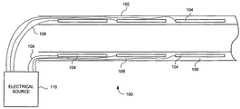
- FIG. 1is an illustration of one advantageous embodiment depicting a portion of the flexible endoscope shaft in which a plurality of segments is positioned along the endoscope shaft.
- FIG. 2is an illustration of an alternative configuration of the plurality of segments according to FIG. 1 .
- FIG. 3is an enlarged view of the embodiment depicted in FIG. 1 showing an inner surface of the shaft.
- FIG. 4is a block diagram of the advantageous embodiment according to FIG. 1 .
- FIG. 4Ais a detail view of a portion of FIG. 4 .
- FIG. 1is an illustration of a portion of a shaft 102 of flexible endoscope 100 .
- the shaft 102is shown as a sectional view including elongated segments 104 , which are positioned within an outer layer 106 of the shaft 102 .
- electrical conductors 108which are individually electrically connected to the various elongated segments 104 .
- the electrical conductors 108generally extend from their respective elongated segment 104 , through the outer layer 106 and are electrically coupled to an electrical source 110 .
- the elongated segments 104are provided as, for example, a fibrous ionic polymeric material (or similar material), which changes in physical characteristics (such as length and rigidity) in response to a stimulus.
- the stimulusis an applied electrical current.
- the applied electrical currentmay be used to achieve variable shaft rigidity, which is controllable by the operator or user.
- the elongated segment 104has a tendency to contract and/or become more rigid.
- the shaft 102may be deflected toward the side on which the simulated elongated segment 104 is located.
- Multiple segmentsmay further be actuated to provide for severe deflection of the shaft 102 . This is highly desirable for the insertion of the endoscope into body cavities having tortuous bends or turns.
- the endoscope 100may further be manipulated by conventional mechanical means, such as, for example, standard cables/wires extending along the length of the shaft 102 , which engage with various portions of the flexible endoscope. In this manner, the endoscope 100 may be inserted into a body cavity having a severe or tortured pathway, but still allow the operator or user full control of the endoscope 100 once the location for the procedure is reached. It is contemplated that the endoscope 100 will be able to maintain the deflected shape during the procedure so as not to put pressure on the surrounding tissue or even displace or damage the tissue.
- both the electrical and the mechanical meansmay be simultaneously used providing absolute control for the operator or user.
- Electrical source 110may be provided as a current source and while each electrical conductor 108 is illustrated connected to the electrical source 110 , it is contemplated that controls are provided to selectively provide electrical current to each elongated segment 104 .
- the amount of deflection and rigidity of each elongated segment 104may be individually controlled based on the total amount of electrical current that is supplied to each elongated segment 104 . For example, greater deflection of a particular elongated segment 104 may be achieved by the application of an increased current. In this manner, a relatively large amount of variable control is provided to the operator or user.
- outer layer 106may, in one advantageous embodiment, comprise an electrically insulated water-tight material to seal the shaft 102 .
- the elongated segmentsare positioned in an end-to-end fashion and may be radially positioned about shaft 102 as illustrated in FIG. 1 .
- FIG. 2illustrates an alternative embodiment for the placement of the elongated segments 104 .
- the elongated segments 104are staggered with respect to each other along the length of the shaft 102 . In this manner, increased control is provided to the operator or user. Many differing configurations of the placement of the elongated segments 104 are possible, whether altering the longitudinal placement or the radial placement of the segments as desired to achieve particular control and deflection of the shaft 102 .
- the shaft 102includes outer layer 106 , in which, elongated segment 104 is positioned. Also illustrated is inner layer 112 , which is positioned along an inner surface 114 of outer layer 106 .
- inner layer 112may, in one advantageous embodiment, comprise a braided material, such as for example, a braided metal material.
- the inner layer 112may comprise, for example, a slotted tube or other flexible material or a combination of both braided and flexible material.
- the elongated segment 104is affixed at end 116 to inner layer 112 .
- both end 116 and end 118may be affixed or attached to inner layer 112 . Accordingly, the elongated segment 104 is compressed between the outer layer 106 and the inner layer 112 .
- elongated segment 102In operation, upon the application of an electrical current to elongated segment 102 via electrical conductor 108 , elongated segment 102 will contract causing the shaft to become harder and less flexible.
- the contraction of the elongated segment 104causes the inner layer 112 , whether comprising a braided material, a slotted tube, other flexible material, or combinations thereof, to displace with respect to the outer layer 106 providing the operator or user with increased control of the shaft 102 .
- the entire shaft 102may comprise the ionic polymer provided as a continuous layer.
- the continuous layeris supplied electrical current via electrical conductor 108 as previous described herein.
- the continuous layermay also be provided with the inner layer 112 as discussed above.
- FIG. 4a block diagram of endoscope 100 is illustrated.
- the shaft 102is illustrated including both the outer layer 106 and the inner layer 112 .
- the endoscope 100is illustrated as comprising a video endoscope, however, it is contemplated that the endoscope 100 may be configured with an eyepiece for direct viewing by the operator or user.
- endoscope 100When used as a video endoscope, endoscope 100 may be provided with an imager (not shown) positioned at a distal end 120 of shaft 102 .
- the imagermay be provided, for example, as a Charged Coupled Device (CCD) or a CMOS device as desired, and may be provided as a hard-wired or wireless device.
- CCDCharged Coupled Device
- CMOScomplementary metal-oxide
- the shaft 102is coupled at a proximal end 122 to handle 124 of endoscope 100 .
- the handle 124is provided having both an electrical interface 126 and a mechanical interface 128 provided for the operator or user.
- the electrical interface 126may be provided as a series of buttons to actuating select elongated segments 104 .
- the mechanical interfacemay comprise any standard interface for mechanically actuating the flexible shaft 102 .
- the mechanical interfacemay comprise a series of levers, knobs, buttons, etc., which interact with a series of wires or cables 113 ( FIG. 4A ) to mechanically deflect shaft 102 as desired.
- the electrical interfacewill, in addition to the mechanical control, allow the operator or user to make portions of the shaft 102 rigid and/or deflect the shaft 102 at relatively severe angles.
- the combination of both electrical control of the polymeric material and mechanical control of the flexible endoscope shaft 102provides increased control, which is highly desirable when performing a procedure in a hard-to-access body cavity.
- video system 130which may further comprise electrical source 110 .
- Video system 130is provided to receive and process image data generated by the imager (not shown) in a video endoscope configuration.
- a conductor 132is provided to supply electrical current to the handle 124 , which is selectively applied to the polymeric material according to the electrical interface actuated by the operator or user. It is further contemplated that the conductor 132 , may comprise an optical cable for supplying illuminating light to the endoscope 100 and may comprise a data channel for receiving image data generated by the imager.
- a light sourcesuch as an LED
- the conductor 132need not comprise a light channel.
- the imagermay be provided as a wireless transmitter, in which case, conductor 132 need not contain a data channel.
- electrical source 110has been illustrated as external to handle 124 , it is contemplated that in one embodiment, it may be positioned in handle 124 as desired or a portion thereof may be positioned in handle 124 .
- a power connectionmay be provided to handle 124
- the power conditioningmay be performed in handle 124 .
- conditioned powermay simply be provided to handle 124 .
- video system display 134may comprise virtually any type of video screen desired by the operator or user, such as, for example, a CRT, an LCD or similar screen. In this manner, the operator or user may clearly view the area ahead of the distal end 120 of shaft 102 to perform the procedure.
Landscapes
- Health & Medical Sciences (AREA)
- Life Sciences & Earth Sciences (AREA)
- Surgery (AREA)
- Biomedical Technology (AREA)
- Medical Informatics (AREA)
- Optics & Photonics (AREA)
- Pathology (AREA)
- Radiology & Medical Imaging (AREA)
- Biophysics (AREA)
- Engineering & Computer Science (AREA)
- Physics & Mathematics (AREA)
- Heart & Thoracic Surgery (AREA)
- Nuclear Medicine, Radiotherapy & Molecular Imaging (AREA)
- Molecular Biology (AREA)
- Animal Behavior & Ethology (AREA)
- General Health & Medical Sciences (AREA)
- Public Health (AREA)
- Veterinary Medicine (AREA)
- Endoscopes (AREA)
- Instruments For Viewing The Inside Of Hollow Bodies (AREA)
Abstract
Description
Claims (16)
Priority Applications (4)
| Application Number | Priority Date | Filing Date | Title |
|---|---|---|---|
| US11/507,230US7789827B2 (en) | 2006-08-21 | 2006-08-21 | Variable shaft flexibility in endoscope |
| CA2593957ACA2593957C (en) | 2006-08-21 | 2007-07-18 | Variable shaft flexibility in endoscope |
| JP2007198047AJP4891174B2 (en) | 2006-08-21 | 2007-07-30 | Endoscopic flexible shaft |
| EP07016246.6AEP1891881B1 (en) | 2006-08-21 | 2007-08-20 | Variable shaft flexibility in endoscope |
Applications Claiming Priority (1)
| Application Number | Priority Date | Filing Date | Title |
|---|---|---|---|
| US11/507,230US7789827B2 (en) | 2006-08-21 | 2006-08-21 | Variable shaft flexibility in endoscope |
Publications (2)
| Publication Number | Publication Date |
|---|---|
| US20080045795A1 US20080045795A1 (en) | 2008-02-21 |
| US7789827B2true US7789827B2 (en) | 2010-09-07 |
Family
ID=38740593
Family Applications (1)
| Application Number | Title | Priority Date | Filing Date |
|---|---|---|---|
| US11/507,230Expired - Fee RelatedUS7789827B2 (en) | 2006-08-21 | 2006-08-21 | Variable shaft flexibility in endoscope |
Country Status (4)
| Country | Link |
|---|---|
| US (1) | US7789827B2 (en) |
| EP (1) | EP1891881B1 (en) |
| JP (1) | JP4891174B2 (en) |
| CA (1) | CA2593957C (en) |
Cited By (25)
| Publication number | Priority date | Publication date | Assignee | Title |
|---|---|---|---|---|
| US20170319048A1 (en)* | 2015-01-28 | 2017-11-09 | Olympus Corporation | Flexible tube insertion apparatus |
| US20190298460A1 (en)* | 2018-03-28 | 2019-10-03 | Auris Health, Inc. | Medical instruments with variable bending stiffness profiles |
| US10667720B2 (en) | 2011-07-29 | 2020-06-02 | Auris Health, Inc. | Apparatus and methods for fiber integration and registration |
| US10716461B2 (en) | 2017-05-17 | 2020-07-21 | Auris Health, Inc. | Exchangeable working channel |
| US10779882B2 (en) | 2009-10-28 | 2020-09-22 | Ethicon Endo-Surgery, Inc. | Electrical ablation devices |
| US10814101B2 (en) | 2014-07-01 | 2020-10-27 | Auris Health, Inc. | Apparatuses and methods for monitoring tendons of steerable catheters |
| US10898276B2 (en) | 2018-08-07 | 2021-01-26 | Auris Health, Inc. | Combining strain-based shape sensing with catheter control |
| US11179212B2 (en) | 2018-09-26 | 2021-11-23 | Auris Health, Inc. | Articulating medical instruments |
| US11213356B2 (en) | 2010-09-17 | 2022-01-04 | Auris Health, Inc. | Systems and methods for positioning an elongate member inside a body |
| US11284918B2 (en) | 2012-05-14 | 2022-03-29 | Cilag GmbH Inlernational | Apparatus for introducing a steerable camera assembly into a patient |
| US11350812B2 (en) | 2018-08-30 | 2022-06-07 | Karl Storz Se & Co. Kg | Endoscope shaft having a layered structure, and method for producing same |
| US11350998B2 (en) | 2014-07-01 | 2022-06-07 | Auris Health, Inc. | Medical instrument having translatable spool |
| US11399834B2 (en) | 2008-07-14 | 2022-08-02 | Cilag Gmbh International | Tissue apposition clip application methods |
| US11413428B2 (en) | 2013-03-15 | 2022-08-16 | Auris Health, Inc. | Catheter insertion system and method of fabrication |
| US11464586B2 (en) | 2009-04-29 | 2022-10-11 | Auris Health, Inc. | Flexible and steerable elongate instruments with shape control and support elements |
| US11484191B2 (en) | 2013-02-27 | 2022-11-01 | Cilag Gmbh International | System for performing a minimally invasive surgical procedure |
| US11617627B2 (en) | 2019-03-29 | 2023-04-04 | Auris Health, Inc. | Systems and methods for optical strain sensing in medical instruments |
| US11701192B2 (en) | 2016-08-26 | 2023-07-18 | Auris Health, Inc. | Steerable catheter with shaft load distributions |
| US11717147B2 (en) | 2019-08-15 | 2023-08-08 | Auris Health, Inc. | Medical device having multiple bending sections |
| US11723636B2 (en) | 2013-03-08 | 2023-08-15 | Auris Health, Inc. | Method, apparatus, and system for facilitating bending of an instrument in a surgical or medical robotic environment |
| US11759605B2 (en) | 2014-07-01 | 2023-09-19 | Auris Health, Inc. | Tool and method for using surgical endoscope with spiral lumens |
| US11819636B2 (en) | 2015-03-30 | 2023-11-21 | Auris Health, Inc. | Endoscope pull wire electrical circuit |
| US11950872B2 (en) | 2019-12-31 | 2024-04-09 | Auris Health, Inc. | Dynamic pulley system |
| US11986257B2 (en) | 2018-12-28 | 2024-05-21 | Auris Health, Inc. | Medical instrument with articulable segment |
| EP4501204A2 (en) | 2014-08-29 | 2025-02-05 | EndoChoice, Inc. | Systems and methods for varying stiffness of an endoscopic insertion tube |
Families Citing this family (54)
| Publication number | Priority date | Publication date | Assignee | Title |
|---|---|---|---|---|
| US7655004B2 (en) | 2007-02-15 | 2010-02-02 | Ethicon Endo-Surgery, Inc. | Electroporation ablation apparatus, system, and method |
| US8075572B2 (en) | 2007-04-26 | 2011-12-13 | Ethicon Endo-Surgery, Inc. | Surgical suturing apparatus |
| US8100922B2 (en) | 2007-04-27 | 2012-01-24 | Ethicon Endo-Surgery, Inc. | Curved needle suturing tool |
| US8579897B2 (en) | 2007-11-21 | 2013-11-12 | Ethicon Endo-Surgery, Inc. | Bipolar forceps |
| US8568410B2 (en) | 2007-08-31 | 2013-10-29 | Ethicon Endo-Surgery, Inc. | Electrical ablation surgical instruments |
| US8262655B2 (en) | 2007-11-21 | 2012-09-11 | Ethicon Endo-Surgery, Inc. | Bipolar forceps |
| US8480657B2 (en) | 2007-10-31 | 2013-07-09 | Ethicon Endo-Surgery, Inc. | Detachable distal overtube section and methods for forming a sealable opening in the wall of an organ |
| US20090112059A1 (en) | 2007-10-31 | 2009-04-30 | Nobis Rudolph H | Apparatus and methods for closing a gastrotomy |
| US8262680B2 (en) | 2008-03-10 | 2012-09-11 | Ethicon Endo-Surgery, Inc. | Anastomotic device |
| US8679003B2 (en) | 2008-05-30 | 2014-03-25 | Ethicon Endo-Surgery, Inc. | Surgical device and endoscope including same |
| US8317806B2 (en) | 2008-05-30 | 2012-11-27 | Ethicon Endo-Surgery, Inc. | Endoscopic suturing tension controlling and indication devices |
| US8771260B2 (en) | 2008-05-30 | 2014-07-08 | Ethicon Endo-Surgery, Inc. | Actuating and articulating surgical device |
| US8070759B2 (en) | 2008-05-30 | 2011-12-06 | Ethicon Endo-Surgery, Inc. | Surgical fastening device |
| US8652150B2 (en) | 2008-05-30 | 2014-02-18 | Ethicon Endo-Surgery, Inc. | Multifunction surgical device |
| US8114072B2 (en) | 2008-05-30 | 2012-02-14 | Ethicon Endo-Surgery, Inc. | Electrical ablation device |
| US8906035B2 (en) | 2008-06-04 | 2014-12-09 | Ethicon Endo-Surgery, Inc. | Endoscopic drop off bag |
| US8403926B2 (en) | 2008-06-05 | 2013-03-26 | Ethicon Endo-Surgery, Inc. | Manually articulating devices |
| US8361112B2 (en) | 2008-06-27 | 2013-01-29 | Ethicon Endo-Surgery, Inc. | Surgical suture arrangement |
| US8262563B2 (en) | 2008-07-14 | 2012-09-11 | Ethicon Endo-Surgery, Inc. | Endoscopic translumenal articulatable steerable overtube |
| US8211125B2 (en) | 2008-08-15 | 2012-07-03 | Ethicon Endo-Surgery, Inc. | Sterile appliance delivery device for endoscopic procedures |
| US8529563B2 (en) | 2008-08-25 | 2013-09-10 | Ethicon Endo-Surgery, Inc. | Electrical ablation devices |
| US8241204B2 (en) | 2008-08-29 | 2012-08-14 | Ethicon Endo-Surgery, Inc. | Articulating end cap |
| US8480689B2 (en) | 2008-09-02 | 2013-07-09 | Ethicon Endo-Surgery, Inc. | Suturing device |
| US8409200B2 (en) | 2008-09-03 | 2013-04-02 | Ethicon Endo-Surgery, Inc. | Surgical grasping device |
| US8114119B2 (en) | 2008-09-09 | 2012-02-14 | Ethicon Endo-Surgery, Inc. | Surgical grasping device |
| US20100076451A1 (en)* | 2008-09-19 | 2010-03-25 | Ethicon Endo-Surgery, Inc. | Rigidizable surgical instrument |
| US8337394B2 (en) | 2008-10-01 | 2012-12-25 | Ethicon Endo-Surgery, Inc. | Overtube with expandable tip |
| US8157834B2 (en) | 2008-11-25 | 2012-04-17 | Ethicon Endo-Surgery, Inc. | Rotational coupling device for surgical instrument with flexible actuators |
| US8172772B2 (en) | 2008-12-11 | 2012-05-08 | Ethicon Endo-Surgery, Inc. | Specimen retrieval device |
| US8361066B2 (en) | 2009-01-12 | 2013-01-29 | Ethicon Endo-Surgery, Inc. | Electrical ablation devices |
| US8828031B2 (en) | 2009-01-12 | 2014-09-09 | Ethicon Endo-Surgery, Inc. | Apparatus for forming an anastomosis |
| US9226772B2 (en) | 2009-01-30 | 2016-01-05 | Ethicon Endo-Surgery, Inc. | Surgical device |
| US8252057B2 (en) | 2009-01-30 | 2012-08-28 | Ethicon Endo-Surgery, Inc. | Surgical access device |
| US8037591B2 (en) | 2009-02-02 | 2011-10-18 | Ethicon Endo-Surgery, Inc. | Surgical scissors |
| US8608652B2 (en) | 2009-11-05 | 2013-12-17 | Ethicon Endo-Surgery, Inc. | Vaginal entry surgical devices, kit, system, and method |
| US8496574B2 (en) | 2009-12-17 | 2013-07-30 | Ethicon Endo-Surgery, Inc. | Selectively positionable camera for surgical guide tube assembly |
| US8353487B2 (en) | 2009-12-17 | 2013-01-15 | Ethicon Endo-Surgery, Inc. | User interface support devices for endoscopic surgical instruments |
| US9028483B2 (en) | 2009-12-18 | 2015-05-12 | Ethicon Endo-Surgery, Inc. | Surgical instrument comprising an electrode |
| US8506564B2 (en) | 2009-12-18 | 2013-08-13 | Ethicon Endo-Surgery, Inc. | Surgical instrument comprising an electrode |
| US9005198B2 (en) | 2010-01-29 | 2015-04-14 | Ethicon Endo-Surgery, Inc. | Surgical instrument comprising an electrode |
| GB201015566D0 (en)* | 2010-09-17 | 2010-10-27 | Rolls Royce Plc | A flexible tool |
| US10092291B2 (en) | 2011-01-25 | 2018-10-09 | Ethicon Endo-Surgery, Inc. | Surgical instrument with selectively rigidizable features |
| US9254169B2 (en) | 2011-02-28 | 2016-02-09 | Ethicon Endo-Surgery, Inc. | Electrical ablation devices and methods |
| US9314620B2 (en) | 2011-02-28 | 2016-04-19 | Ethicon Endo-Surgery, Inc. | Electrical ablation devices and methods |
| US9233241B2 (en) | 2011-02-28 | 2016-01-12 | Ethicon Endo-Surgery, Inc. | Electrical ablation devices and methods |
| US9049987B2 (en) | 2011-03-17 | 2015-06-09 | Ethicon Endo-Surgery, Inc. | Hand held surgical device for manipulating an internal magnet assembly within a patient |
| US8986199B2 (en) | 2012-02-17 | 2015-03-24 | Ethicon Endo-Surgery, Inc. | Apparatus and methods for cleaning the lens of an endoscope |
| US9078662B2 (en) | 2012-07-03 | 2015-07-14 | Ethicon Endo-Surgery, Inc. | Endoscopic cap electrode and method for using the same |
| US9545290B2 (en) | 2012-07-30 | 2017-01-17 | Ethicon Endo-Surgery, Inc. | Needle probe guide |
| US9572623B2 (en) | 2012-08-02 | 2017-02-21 | Ethicon Endo-Surgery, Inc. | Reusable electrode and disposable sheath |
| US10314649B2 (en) | 2012-08-02 | 2019-06-11 | Ethicon Endo-Surgery, Inc. | Flexible expandable electrode and method of intraluminal delivery of pulsed power |
| US9277957B2 (en) | 2012-08-15 | 2016-03-08 | Ethicon Endo-Surgery, Inc. | Electrosurgical devices and methods |
| US11530621B2 (en)* | 2019-10-16 | 2022-12-20 | General Electric Company | Systems and method for use in servicing a machine |
| WO2024187141A2 (en)* | 2023-03-08 | 2024-09-12 | Georgia Tech Research Corporation | Systems and methods to achieve variable stiffness in a continuum structure |
Citations (17)
| Publication number | Priority date | Publication date | Assignee | Title |
|---|---|---|---|---|
| US5482029A (en) | 1992-06-26 | 1996-01-09 | Kabushiki Kaisha Toshiba | Variable flexibility endoscope system |
| US6187026B1 (en)* | 1995-02-09 | 2001-02-13 | Atraumatic Limited | Surgical instruments |
| US6293907B1 (en)* | 1996-05-23 | 2001-09-25 | Anthony Thomas Roger Axon | Endoscope cover having protrusions |
| US20030065373A1 (en) | 2001-10-02 | 2003-04-03 | Lovett Eric G. | Medical device having rheometric materials and method therefor |
| US6562021B1 (en)* | 1997-12-22 | 2003-05-13 | Micrus Corporation | Variable stiffness electrically conductive composite, resistive heating catheter shaft |
| US6679836B2 (en) | 2002-06-21 | 2004-01-20 | Scimed Life Systems, Inc. | Universal programmable guide catheter |
| US6770027B2 (en) | 2001-10-05 | 2004-08-03 | Scimed Life Systems, Inc. | Robotic endoscope with wireless interface |
| US20040176664A1 (en) | 2002-10-29 | 2004-09-09 | Iddan Gavriel J. | In-vivo extendable element device and system, and method of use |
| US6835173B2 (en) | 2001-10-05 | 2004-12-28 | Scimed Life Systems, Inc. | Robotic endoscope |
| US20050085693A1 (en)* | 2000-04-03 | 2005-04-21 | Amir Belson | Activated polymer articulated instruments and methods of insertion |
| US6887235B2 (en) | 1999-03-24 | 2005-05-03 | Micrus Corporation | Variable stiffness heating catheter |
| US6942613B2 (en) | 2002-06-13 | 2005-09-13 | Usgi Medical Inc. | Shape lockable apparatus and method for advancing an instrument through unsupported anatomy |
| US20050203382A1 (en) | 2004-02-23 | 2005-09-15 | Assaf Govari | Robotically guided catheter |
| US20050250990A1 (en) | 2004-05-10 | 2005-11-10 | Usgi Medical Inc. | Shape lockable apparatus and method for advancing an instrument through unsupported anatomy |
| US20050272976A1 (en) | 2004-03-15 | 2005-12-08 | Olympus Corporation | Endoscope insertion aiding device |
| WO2006028019A1 (en) | 2004-09-07 | 2006-03-16 | Olympus Corporation | Endoscope |
| US20060060207A1 (en) | 2004-09-21 | 2006-03-23 | Hegde Anant V | Airway implant and methods of making and using |
Family Cites Families (2)
| Publication number | Priority date | Publication date | Assignee | Title |
|---|---|---|---|---|
| JP3652138B2 (en)* | 1998-09-18 | 2005-05-25 | オリンパス株式会社 | Endoscope |
| JP4593160B2 (en)* | 2003-04-25 | 2010-12-08 | イーメックス株式会社 | Bending drive device and micro device |
- 2006
- 2006-08-21USUS11/507,230patent/US7789827B2/ennot_activeExpired - Fee Related
- 2007
- 2007-07-18CACA2593957Apatent/CA2593957C/ennot_activeExpired - Fee Related
- 2007-07-30JPJP2007198047Apatent/JP4891174B2/ennot_activeExpired - Fee Related
- 2007-08-20EPEP07016246.6Apatent/EP1891881B1/ennot_activeCeased
Patent Citations (22)
| Publication number | Priority date | Publication date | Assignee | Title |
|---|---|---|---|---|
| US5482029A (en) | 1992-06-26 | 1996-01-09 | Kabushiki Kaisha Toshiba | Variable flexibility endoscope system |
| US6187026B1 (en)* | 1995-02-09 | 2001-02-13 | Atraumatic Limited | Surgical instruments |
| US6293907B1 (en)* | 1996-05-23 | 2001-09-25 | Anthony Thomas Roger Axon | Endoscope cover having protrusions |
| US6562021B1 (en)* | 1997-12-22 | 2003-05-13 | Micrus Corporation | Variable stiffness electrically conductive composite, resistive heating catheter shaft |
| US6887235B2 (en) | 1999-03-24 | 2005-05-03 | Micrus Corporation | Variable stiffness heating catheter |
| US20060258912A1 (en)* | 2000-04-03 | 2006-11-16 | Amir Belson | Activated polymer articulated instruments and methods of insertion |
| US20050085693A1 (en)* | 2000-04-03 | 2005-04-21 | Amir Belson | Activated polymer articulated instruments and methods of insertion |
| US20030065373A1 (en) | 2001-10-02 | 2003-04-03 | Lovett Eric G. | Medical device having rheometric materials and method therefor |
| US7097615B2 (en)* | 2001-10-05 | 2006-08-29 | Boston Scientific Scimed, Inc. | Robotic endoscope with wireless interface |
| US6770027B2 (en) | 2001-10-05 | 2004-08-03 | Scimed Life Systems, Inc. | Robotic endoscope with wireless interface |
| US6835173B2 (en) | 2001-10-05 | 2004-12-28 | Scimed Life Systems, Inc. | Robotic endoscope |
| US6942613B2 (en) | 2002-06-13 | 2005-09-13 | Usgi Medical Inc. | Shape lockable apparatus and method for advancing an instrument through unsupported anatomy |
| US6679836B2 (en) | 2002-06-21 | 2004-01-20 | Scimed Life Systems, Inc. | Universal programmable guide catheter |
| US6997870B2 (en)* | 2002-06-21 | 2006-02-14 | Boston Scientific Scimed, Inc. | Universal, programmable guide catheter |
| US20060111618A1 (en)* | 2002-06-21 | 2006-05-25 | Couvillon Lucien A Jr | Universal, programmable guide catheter |
| US20040176664A1 (en) | 2002-10-29 | 2004-09-09 | Iddan Gavriel J. | In-vivo extendable element device and system, and method of use |
| US20050203382A1 (en) | 2004-02-23 | 2005-09-15 | Assaf Govari | Robotically guided catheter |
| US20050272976A1 (en) | 2004-03-15 | 2005-12-08 | Olympus Corporation | Endoscope insertion aiding device |
| US20050250990A1 (en) | 2004-05-10 | 2005-11-10 | Usgi Medical Inc. | Shape lockable apparatus and method for advancing an instrument through unsupported anatomy |
| WO2006028019A1 (en) | 2004-09-07 | 2006-03-16 | Olympus Corporation | Endoscope |
| EP1787575A1 (en) | 2004-09-07 | 2007-05-23 | Olympus Corporation | Endoscope |
| US20060060207A1 (en) | 2004-09-21 | 2006-03-23 | Hegde Anant V | Airway implant and methods of making and using |
Non-Patent Citations (1)
| Title |
|---|
| Extended European Search Report, EP07016246, Dec. 14, 2007, 9 pages. |
Cited By (35)
| Publication number | Priority date | Publication date | Assignee | Title |
|---|---|---|---|---|
| US11399834B2 (en) | 2008-07-14 | 2022-08-02 | Cilag Gmbh International | Tissue apposition clip application methods |
| US11464586B2 (en) | 2009-04-29 | 2022-10-11 | Auris Health, Inc. | Flexible and steerable elongate instruments with shape control and support elements |
| US10779882B2 (en) | 2009-10-28 | 2020-09-22 | Ethicon Endo-Surgery, Inc. | Electrical ablation devices |
| US12310669B2 (en) | 2010-09-17 | 2025-05-27 | Auris Health, Inc. | Systems and methods for positioning an elongate member inside a body |
| US11213356B2 (en) | 2010-09-17 | 2022-01-04 | Auris Health, Inc. | Systems and methods for positioning an elongate member inside a body |
| US10667720B2 (en) | 2011-07-29 | 2020-06-02 | Auris Health, Inc. | Apparatus and methods for fiber integration and registration |
| US11419518B2 (en) | 2011-07-29 | 2022-08-23 | Auris Health, Inc. | Apparatus and methods for fiber integration and registration |
| US11284918B2 (en) | 2012-05-14 | 2022-03-29 | Cilag GmbH Inlernational | Apparatus for introducing a steerable camera assembly into a patient |
| US11484191B2 (en) | 2013-02-27 | 2022-11-01 | Cilag Gmbh International | System for performing a minimally invasive surgical procedure |
| US11723636B2 (en) | 2013-03-08 | 2023-08-15 | Auris Health, Inc. | Method, apparatus, and system for facilitating bending of an instrument in a surgical or medical robotic environment |
| US11413428B2 (en) | 2013-03-15 | 2022-08-16 | Auris Health, Inc. | Catheter insertion system and method of fabrication |
| US11759605B2 (en) | 2014-07-01 | 2023-09-19 | Auris Health, Inc. | Tool and method for using surgical endoscope with spiral lumens |
| US10814101B2 (en) | 2014-07-01 | 2020-10-27 | Auris Health, Inc. | Apparatuses and methods for monitoring tendons of steerable catheters |
| US11350998B2 (en) | 2014-07-01 | 2022-06-07 | Auris Health, Inc. | Medical instrument having translatable spool |
| US11511079B2 (en) | 2014-07-01 | 2022-11-29 | Auris Health, Inc. | Apparatuses and methods for monitoring tendons of steerable catheters |
| EP4501204A2 (en) | 2014-08-29 | 2025-02-05 | EndoChoice, Inc. | Systems and methods for varying stiffness of an endoscopic insertion tube |
| US20170319048A1 (en)* | 2015-01-28 | 2017-11-09 | Olympus Corporation | Flexible tube insertion apparatus |
| US11819636B2 (en) | 2015-03-30 | 2023-11-21 | Auris Health, Inc. | Endoscope pull wire electrical circuit |
| US11701192B2 (en) | 2016-08-26 | 2023-07-18 | Auris Health, Inc. | Steerable catheter with shaft load distributions |
| US12295692B2 (en) | 2016-08-26 | 2025-05-13 | Auris Health, Inc. | Steerable catheter with shaft load distributions |
| US10716461B2 (en) | 2017-05-17 | 2020-07-21 | Auris Health, Inc. | Exchangeable working channel |
| US11730351B2 (en) | 2017-05-17 | 2023-08-22 | Auris Health, Inc. | Exchangeable working channel |
| US12396808B2 (en) | 2018-03-28 | 2025-08-26 | Auris Health, Inc. | Medical instruments with variable bending stiffness profiles |
| US11109920B2 (en)* | 2018-03-28 | 2021-09-07 | Auris Health, Inc. | Medical instruments with variable bending stiffness profiles |
| US20190298460A1 (en)* | 2018-03-28 | 2019-10-03 | Auris Health, Inc. | Medical instruments with variable bending stiffness profiles |
| US10898276B2 (en) | 2018-08-07 | 2021-01-26 | Auris Health, Inc. | Combining strain-based shape sensing with catheter control |
| US12390286B2 (en) | 2018-08-07 | 2025-08-19 | Auris Health, Inc. | Instrument shape determination |
| US11779400B2 (en) | 2018-08-07 | 2023-10-10 | Auris Health, Inc. | Combining strain-based shape sensing with catheter control |
| US11350812B2 (en) | 2018-08-30 | 2022-06-07 | Karl Storz Se & Co. Kg | Endoscope shaft having a layered structure, and method for producing same |
| US11179212B2 (en) | 2018-09-26 | 2021-11-23 | Auris Health, Inc. | Articulating medical instruments |
| US11779421B2 (en) | 2018-09-26 | 2023-10-10 | Auris Health, Inc. | Articulating medical instruments |
| US11986257B2 (en) | 2018-12-28 | 2024-05-21 | Auris Health, Inc. | Medical instrument with articulable segment |
| US11617627B2 (en) | 2019-03-29 | 2023-04-04 | Auris Health, Inc. | Systems and methods for optical strain sensing in medical instruments |
| US11717147B2 (en) | 2019-08-15 | 2023-08-08 | Auris Health, Inc. | Medical device having multiple bending sections |
| US11950872B2 (en) | 2019-12-31 | 2024-04-09 | Auris Health, Inc. | Dynamic pulley system |
Also Published As
| Publication number | Publication date |
|---|---|
| CA2593957A1 (en) | 2008-02-21 |
| JP4891174B2 (en) | 2012-03-07 |
| US20080045795A1 (en) | 2008-02-21 |
| CA2593957C (en) | 2011-10-11 |
| EP1891881B1 (en) | 2014-04-09 |
| EP1891881A1 (en) | 2008-02-27 |
| JP2008049151A (en) | 2008-03-06 |
Similar Documents
| Publication | Publication Date | Title |
|---|---|---|
| US7789827B2 (en) | Variable shaft flexibility in endoscope | |
| US20230389781A1 (en) | Systems and methods for varying stiffness of an endoscopic insertion tube | |
| CA2898586C (en) | Integrated steering device | |
| US9345390B2 (en) | Endoscope flexible tube and endoscope device | |
| EP1558124B1 (en) | Endoscopic imaging system including removable deflection device | |
| US20220304550A1 (en) | Systems and methods for modular endoscope | |
| US20090231419A1 (en) | Endoscope Assembly and Method of Performing a Medical Procedure | |
| US20050182298A1 (en) | Cardiac tissue ablation instrument with flexible wrist | |
| US20090030282A1 (en) | Controllable dexterous endoscopic device | |
| US20050107669A1 (en) | Robotic endoscope | |
| EP2211683A2 (en) | Endoscope assembly comprising retrograde viewing imaging device and instrument channel | |
| US20130053645A1 (en) | Disposable sheath with lighting | |
| WO2006033671A2 (en) | Endoscopic surgical access devices and methods of articulating an external accessory channel | |
| US20250248588A1 (en) | Systems and methods for medical device intubation | |
| US20190269301A1 (en) | Endoscopic Device | |
| US20240285150A1 (en) | Systems and methods for endoscope proximal end design | |
| CN212661780U (en) | endoscope | |
| US20240260820A1 (en) | Systems and methods for configurable endoscope bending section | |
| JPH06277174A (en) | Endoscope apparatus | |
| WO2017134912A1 (en) | Method for producing endoscope, and endoscope |
Legal Events
| Date | Code | Title | Description |
|---|---|---|---|
| AS | Assignment | Owner name:KARL STORZ ENDOVISION, MASSACHUSETTS Free format text:ASSIGNMENT OF ASSIGNORS INTEREST;ASSIGNOR:LANDRY, DANA J.;REEL/FRAME:018198/0782 Effective date:20060801 | |
| AS | Assignment | Owner name:KARL STORZ ENDOVISION, INC., MASSACHUSETTS Free format text:CORRECTIVE ASSIGNMENT TO CORRECT THE ASSIGNEE NAME PREVIOUSLY RECORDED ON REEL 018198 FRAME 0782;ASSIGNOR:LANDRY, DANA J.;REEL/FRAME:019148/0083 Effective date:20060801 Owner name:KARL STORZ ENDOVISION, INC., MASSACHUSETTS Free format text:CORRECTIVE ASSIGNMENT TO CORRECT THE ASSIGNEE NAME PREVIOUSLY RECORDED ON REEL 018198 FRAME 0782. ASSIGNOR(S) HEREBY CONFIRMS THE ASSIGNMENT OF ASSIGNOR'S INTEREST;ASSIGNOR:LANDRY, DANA J.;REEL/FRAME:019148/0083 Effective date:20060801 | |
| STCF | Information on status: patent grant | Free format text:PATENTED CASE | |
| FEPP | Fee payment procedure | Free format text:PAYOR NUMBER ASSIGNED (ORIGINAL EVENT CODE: ASPN); ENTITY STATUS OF PATENT OWNER: LARGE ENTITY | |
| FPAY | Fee payment | Year of fee payment:4 | |
| MAFP | Maintenance fee payment | Free format text:PAYMENT OF MAINTENANCE FEE, 8TH YEAR, LARGE ENTITY (ORIGINAL EVENT CODE: M1552) Year of fee payment:8 | |
| FEPP | Fee payment procedure | Free format text:MAINTENANCE FEE REMINDER MAILED (ORIGINAL EVENT CODE: REM.); ENTITY STATUS OF PATENT OWNER: LARGE ENTITY | |
| LAPS | Lapse for failure to pay maintenance fees | Free format text:PATENT EXPIRED FOR FAILURE TO PAY MAINTENANCE FEES (ORIGINAL EVENT CODE: EXP.); ENTITY STATUS OF PATENT OWNER: LARGE ENTITY | |
| STCH | Information on status: patent discontinuation | Free format text:PATENT EXPIRED DUE TO NONPAYMENT OF MAINTENANCE FEES UNDER 37 CFR 1.362 | |
| FP | Lapsed due to failure to pay maintenance fee | Effective date:20220907 |