US7789676B2 - Electrical connector with electrically shielded terminals - Google Patents
Electrical connector with electrically shielded terminalsDownload PDFInfo
- Publication number
- US7789676B2 US7789676B2US12/194,293US19429308AUS7789676B2US 7789676 B2US7789676 B2US 7789676B2US 19429308 AUS19429308 AUS 19429308AUS 7789676 B2US7789676 B2US 7789676B2
- Authority
- US
- United States
- Prior art keywords
- dielectric core
- terminals
- electrically conductive
- length
- conductive shell
- Prior art date
- Legal status (The legal status is an assumption and is not a legal conclusion. Google has not performed a legal analysis and makes no representation as to the accuracy of the status listed.)
- Active, expires
Links
- 230000013011matingEffects0.000claimsabstractdescription43
- 238000000034methodMethods0.000description21
- 238000001465metallisationMethods0.000description10
- 239000000463materialSubstances0.000description7
- 239000004020conductorSubstances0.000description4
- RYGMFSIKBFXOCR-UHFFFAOYSA-NCopperChemical compound[Cu]RYGMFSIKBFXOCR-UHFFFAOYSA-N0.000description2
- BQCADISMDOOEFD-UHFFFAOYSA-NSilverChemical compound[Ag]BQCADISMDOOEFD-UHFFFAOYSA-N0.000description2
- XAGFODPZIPBFFR-UHFFFAOYSA-NaluminiumChemical compound[Al]XAGFODPZIPBFFR-UHFFFAOYSA-N0.000description2
- 229910052782aluminiumInorganic materials0.000description2
- 229910052802copperInorganic materials0.000description2
- 239000010949copperSubstances0.000description2
- 239000012799electrically-conductive coatingSubstances0.000description2
- 238000007772electroless platingMethods0.000description2
- 238000009713electroplatingMethods0.000description2
- 239000011888foilSubstances0.000description2
- PCHJSUWPFVWCPO-UHFFFAOYSA-NgoldChemical compound[Au]PCHJSUWPFVWCPO-UHFFFAOYSA-N0.000description2
- 229910052737goldInorganic materials0.000description2
- 239000010931goldSubstances0.000description2
- 238000000465mouldingMethods0.000description2
- 238000010422paintingMethods0.000description2
- 239000004033plasticSubstances0.000description2
- 229920003023plasticPolymers0.000description2
- 238000007747platingMethods0.000description2
- 229910052709silverInorganic materials0.000description2
- 239000004332silverSubstances0.000description2
- 238000005507sprayingMethods0.000description2
- 238000004544sputter depositionMethods0.000description2
- 239000000126substanceSubstances0.000description2
- 238000012546transferMethods0.000description2
- 238000007738vacuum evaporationMethods0.000description2
- 238000013459approachMethods0.000description1
- 238000012986modificationMethods0.000description1
- 230000004048modificationEffects0.000description1
- 239000000758substrateSubstances0.000description1
- 239000011800void materialSubstances0.000description1
Images


Classifications
- H—ELECTRICITY
- H01—ELECTRIC ELEMENTS
- H01R—ELECTRICALLY-CONDUCTIVE CONNECTIONS; STRUCTURAL ASSOCIATIONS OF A PLURALITY OF MUTUALLY-INSULATED ELECTRICAL CONNECTING ELEMENTS; COUPLING DEVICES; CURRENT COLLECTORS
- H01R13/00—Details of coupling devices of the kinds covered by groups H01R12/70 or H01R24/00 - H01R33/00
- H01R13/648—Protective earth or shield arrangements on coupling devices, e.g. anti-static shielding
- H01R13/658—High frequency shielding arrangements, e.g. against EMI [Electro-Magnetic Interference] or EMP [Electro-Magnetic Pulse]
- H01R13/6598—Shield material
- H01R13/6599—Dielectric material made conductive, e.g. plastic material coated with metal
- H—ELECTRICITY
- H01—ELECTRIC ELEMENTS
- H01R—ELECTRICALLY-CONDUCTIVE CONNECTIONS; STRUCTURAL ASSOCIATIONS OF A PLURALITY OF MUTUALLY-INSULATED ELECTRICAL CONNECTING ELEMENTS; COUPLING DEVICES; CURRENT COLLECTORS
- H01R13/00—Details of coupling devices of the kinds covered by groups H01R12/70 or H01R24/00 - H01R33/00
- H01R13/648—Protective earth or shield arrangements on coupling devices, e.g. anti-static shielding
- H01R13/658—High frequency shielding arrangements, e.g. against EMI [Electro-Magnetic Interference] or EMP [Electro-Magnetic Pulse]
- H01R13/6581—Shield structure
- H01R13/6585—Shielding material individually surrounding or interposed between mutually spaced contacts
- H01R13/6586—Shielding material individually surrounding or interposed between mutually spaced contacts for separating multiple connector modules
- H01R13/6587—Shielding material individually surrounding or interposed between mutually spaced contacts for separating multiple connector modules for mounting on PCBs
- H—ELECTRICITY
- H01—ELECTRIC ELEMENTS
- H01R—ELECTRICALLY-CONDUCTIVE CONNECTIONS; STRUCTURAL ASSOCIATIONS OF A PLURALITY OF MUTUALLY-INSULATED ELECTRICAL CONNECTING ELEMENTS; COUPLING DEVICES; CURRENT COLLECTORS
- H01R12/00—Structural associations of a plurality of mutually-insulated electrical connecting elements, specially adapted for printed circuits, e.g. printed circuit boards [PCB], flat or ribbon cables, or like generally planar structures, e.g. terminal strips, terminal blocks; Coupling devices specially adapted for printed circuits, flat or ribbon cables, or like generally planar structures; Terminals specially adapted for contact with, or insertion into, printed circuits, flat or ribbon cables, or like generally planar structures
- H01R12/70—Coupling devices
- H01R12/71—Coupling devices for rigid printing circuits or like structures
- H01R12/72—Coupling devices for rigid printing circuits or like structures coupling with the edge of the rigid printed circuits or like structures
- H01R12/722—Coupling devices for rigid printing circuits or like structures coupling with the edge of the rigid printed circuits or like structures coupling devices mounted on the edge of the printed circuits
- H01R12/724—Coupling devices for rigid printing circuits or like structures coupling with the edge of the rigid printed circuits or like structures coupling devices mounted on the edge of the printed circuits containing contact members forming a right angle
Definitions
- the subject matter described and/or illustrated hereinrelates generally to electrical connectors, and more particularly, to lead frames for electrical connectors.
- the back planetypically has a connector, commonly referred to as a header, that includes a plurality of signal pins or contacts which connect to conductive traces on the back plane.
- the daughter board connectorcommonly referred to as a receptacle, also includes a plurality of contacts or pins.
- the receptacleis a right angle connector that interconnects the back plane with the daughter board so that signals can be routed therebetween.
- the right angle connectortypically includes a mating face that receives the plurality of signal pins from the header on the back plane, and contacts that connect to the daughter board.
- Some right angle connectorsinclude a plurality of contact modules that are received in a housing.
- Each contact moduleincludes a lead frame having a plurality of electrical terminals encased within a body.
- Contact modulesmust therefore handle ever increasing signal speeds at ever increasing signal densities.
- increasing signal speed and/or densitymay introduce more signal noise, commonly referred to as crosstalk, between terminals within a single lead frame and/or between the terminals of the lead frames of adjacent contact modules within the connector.
- increasing signal frequenciescan lead to the generation of undesired signal propagation modes.
- an electrical connectorin one embodiment, includes a housing and a lead frame held by the housing.
- the lead frameincludes a terminal extending along a length between a mating end portion and a mounting end portion.
- the terminalis at least partially surrounded by a dielectric core extending a length along at least a portion of the length of the terminal.
- the dielectric coreis metallized such that the core is at least partially surrounded by an electrically conductive shell.
- a contact modulefor an electrical connector.
- the contact moduleincludes a lead frame having a plurality of terminals each extending along a length between a mating end portion and a mounting end portion. Each terminal is at least partially surrounded by a separate dielectric core extending a length along at least a portion of the length of the corresponding terminal. Each of the dielectric cores is at least partially surrounded by a separate electrically conductive shell.
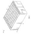
- FIG. 1is a perspective view of an exemplary embodiment of an electrical connector.
- FIG. 2is a perspective view of an exemplary embodiment of a housing of the electrical connector shown in FIG. 1 .
- FIG. 3is cross-sectional view of a portion of the electrical connector shown in FIG. 1 taken along line 3 - 3 of FIG. 1 .
- FIG. 4is a perspective view of an exemplary embodiment of a contact module for use with the connector shown in FIG. 1 .
- FIG. 5is a side view of the contact module shown in FIG. 4 .
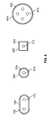
- FIG. 6illustrates a plurality of non-limiting exemplary shapes for dielectric cores, terminals, and electrically conductive shells of the contact module shown in FIGS. 4 and 5 .
- FIG. 7illustrates an exemplary alternative embodiment of an arrangement of the dielectric cores of a contact module.
- FIG. 8illustrates an exemplary alternative embodiment of an electrically conductive shell for use with the contact module shown in FIGS. 4 and 5 .
- FIG. 9illustrates another exemplary embodiment of an electrically conductive shell for use with the contact module shown in FIGS. 4 and 5 .
- FIG. 10is a side view of an exemplary alternative embodiment of a contact module for use with the connector shown in FIG. 1 .
- FIG. 11is a perspective view of the contact module shown in FIG. 10 .
- FIG. 1is a perspective view of an exemplary embodiment of an electrical connector 10 .
- the connector 10includes a dielectric housing 12 having a forward mating end 14 that includes a shroud 16 and a mating face 18 .
- the mating face 18includes a plurality of mating contacts 20 (shown in FIGS. 4 and 5 ), such as, for example, contacts within contact cavities 22 , that are configured to receive corresponding mating contacts (not shown) from a mating connector (not shown).
- the shroud 16includes an upper surface 24 and a lower surface 26 between opposite sides 28 .
- the upper and lower surfaces 24 and 26respectively, each includes an optional chamfered forward edge portion 30 .
- the sides 28each include optional chamfered side edge portions 32 .
- an alignment rib 34is formed on the upper shroud surface 24 and lower shroud surface 26 .
- the chamfered edge portions 30 and 32 and the alignment ribs 34cooperate to bring the connector 10 into alignment with the mating connector during the mating process so that the contacts in the mating connector are received in the contact cavities 22 without damage.
- a plurality of contact modules 36are received in the housing 12 from a rearward end 38 .
- the contact modules 36define a connector mounting face 40 .
- the connector mounting face 40includes a plurality of contacts 42 that are configured to be mounted to a substrate (not shown), such as, but not limited to, a circuit board.
- the mounting face 40is approximately perpendicular to the mating face 18 such that the connector 10 interconnects electrical components that are approximately at a right angle to one another.
- the mounting face 40may be angled at any other suitable angle relative to the mating face 18 that enables the connector 10 to interconnect electrical components that are oriented at any other angle relative to each other.
- the housing 12may hold any number of contact modules 36 . As will be described below, in the exemplary embodiment of FIGS. 1-5 , when the contact modules 36 are held by the housing 12 the contact modules 36 are held together by a plurality of holders 44 .
- FIG. 2is a perspective view of the housing 12 .
- the housing 12includes a plurality of dividing walls 46 that define a plurality of chambers 48 .
- the chambers 48receive a forward portion of the contact modules 36 ( FIGS. 1 , 4 , and 5 ).
- the chambers 48stabilize the contact modules 36 when the contact modules 36 are loaded into the housing 12 .
- the chambers 48each have about an equal width. However, one or more of the chambers 48 may different widths for accommodating differently sized contact modules 36 .
- FIG. 3is cross-sectional view of a portion of the electrical connector 10 taken along line 3 - 3 of FIG. 1 .
- the contact modules 36are held together by the plurality of holders 44 .
- the holders 44are positioned adjacent opposite side portions 50 and 52 of each the contact modules 36 .
- Each holder 44includes a body 56 having a central portion 58 and a plurality of extensions 60 that extend outwardly from the central portion 58 .
- the extensions 60extend into gaps 62 between portions of each adjacent contact module 36 to support and hold the contact modules 36 together.
- the holders 44may optionally include an extension 61 ( FIG. 1 ) at opposite end portions thereof for supporting the upper and lower-most portions of the contact modules 36 .
- a “contact module”may include one or both of the adjacent holders 44 .
- the contact modules 36may each include any other suitable structure that enables the electrical connector 10 and the contact modules 36 to function as described and/or illustrated herein.
- Each holder 44may include any number of the extensions 60 for supporting any number of dielectric cores 54 .
- FIGS. 4 and 5are perspective and side views, respectively, of an exemplary embodiment of the contact module 36 .
- the contact module 36includes a lead frame 70 (best seen in FIG. 5 ) that includes a plurality of electrical terminals 72 .
- the terminals 72extend along predetermined paths to electrically connect each mating contact 20 with each mounting contact 42 .
- the terminals 72extend between a mating end portion 74 and a mounting end portion 76 .
- Each terminal 72may be either a signal terminal, a ground terminal, or a power terminal.
- the terminals 72are arranged in differential pairs. In the exemplary embodiment of FIGS.
- the terminals 72 of each differential pairare arranged side-by-side in a row.
- the plurality of rows of differential pairsare arranged in a single column such that one terminal 72 from each of the differential pairs is arrange in a column C 1 with corresponding terminals 72 of the other differential pairs and the other terminal from each of the differential pairs is arranged in a column C 2 with corresponding terminals 72 of the other differential pairs.
- each differential pair of terminals 72is at least partially encased in, or surrounded by, a separate dielectric core 54 .
- Each dielectric core 54extends a length between a mating face 78 and a mounting face 80 that defines a portion of the mounting face 40 .
- the mating contacts 20extend from the terminal mating end portions 74 and the mating faces 78 and the mounting contacts 42 extend from the terminal mounting end portions 76 and the mounting faces 80 .
- each dielectric core 54extends approximately along the entire length of the corresponding differential pair of terminals 72 from the mating end portion 74 to the mounting end portion 76 thereof.
- Each dielectric core 54includes an exterior surface 77 having a circumference, which is best seen in FIG. 3 .
- each dielectric core 54has an approximately rectangular cross-sectional shape about the entirety of the length thereof. Accordingly, in the exemplary embodiment of FIGS. 1-5 , each dielectric core 54 includes four sides 81 , which are best seen in FIG. 3 .
- one or more of the dielectric cores 54may include an air gap (not shown).
- the mounting faces 80 of the dielectric cores 54are approximately perpendicular to the mating faces 78 such that the connector 10 interconnects electrical components that are approximately at a right angle to one another.
- the mounting faces 80may be angled at any other suitable angle relative to the mating faces 78 that enables the connector 10 to interconnect electrical components that are oriented at any other angle relative to each other.
- each dielectric core 54may extend along only a portion of the length of the corresponding differential pair of terminals 72 , including embodiments wherein a dielectric core 54 is interrupted along its length such that the dielectric core 54 includes two segments that are not connected together. In such an embodiment wherein a dielectric core 54 includes two segments that are not connected together, the two segments are considered to be one dielectric core 54 . In embodiments wherein a dielectric core 54 includes an air gap, if the air gap separates the dielectric core 54 of a differential pair of terminals 72 into two segments that are not connected together, the two segments are considered to be one dielectric core 54 .
- each of the dielectric cores 54has an approximately rectangular cross-sectional shape along an approximate entirety of the length thereof, each dielectric core 54 may include any suitable cross-sectional shape(s) along the length thereof. Moreover, each dielectric core 54 may include any number of sides 81 .
- FIG. 6illustrates a plurality of non-limiting exemplary cross-sectional shapes of a plurality of dielectric cores 154 , 254 , 354 , and 454 .
- FIGS. 3-5although in the exemplary embodiment of FIGS.
- each of the terminals 72has an approximately rectangular cross-sectional shape, each terminal 72 may include any suitable cross-sectional shape(s) and the terminals 72 may be arranged within the corresponding dielectric core 54 in any suitable arrangement and/or the like.
- FIG. 6also illustrates a plurality of non-limiting exemplary cross-sectional shapes of terminals 172 , 272 , 372 , and 472 as well as non-limiting exemplary arrangements of how the terminals 172 , 272 , 372 , and 472 are held within the respective dielectric cores 154 , 254 , 354 , and 454 .
- Each contact module 36is shown as having eight differential pairs of terminals 72 . However, the contact module 36 may each include any number of differential pairs of terminals 72 . Moreover, although the contact module 36 is shown as having sixteen terminals 72 , the contact module 36 may include any number of terminals 72 . In some alternative embodiments, the contact module 36 includes only a single column of terminals 72 such that each core 54 at least partially surrounds only a single one of the terminals 72 , wherein some adjacent pairs of terminals 72 within the single column are optionally arranged as differential pairs. Although the dielectric cores 54 of each contact modules 36 are shown herein as being aligned along a single line, the dielectric cores 54 are not limited thereto. For example, FIG. 7 illustrates a contact module 536 having a plurality of dielectric cores 554 that are aligned in a column. Adjacent dielectric cores 554 are staggered on opposite sides of a central line 555 of the column.
- a separate electrically conductive shell 82surrounds at least a portion of each of the dielectric cores 54 .
- the electrically conductive shell 82may facilitate electrically shielding the terminals 72 of each differential pair from the terminals 72 of adjacent differential pairs of the corresponding contact module 36 and/or of adjacent contact modules 36 .
- the electrically conductive shell 82may facilitate providing the corresponding differential pair of terminals 72 with a desired impedance.
- each electrically conductive shell 82extends approximately along the entire length of the corresponding dielectric core 54 from the mating face 78 to the mounting face 80 thereof. Moreover, each electrically conductive shell 82 surrounds an approximate entirety of the circumference of the corresponding dielectric core 54 along approximately the entire length of the corresponding dielectric core 54 . Accordingly, in the exemplary embodiment of FIGS. 1-5 each electrically conductive shell 82 defines a conduit that completely surrounds the circumference of the corresponding dielectric core 54 from the mating face 78 to the mounting face 80 thereof. As shown in FIGS. 3 and 4 , each electrically conductive shell 82 has an approximately rectangular cross-sectional shape about the entirety of the length thereof.
- each electrically conductive shell 82includes four sides 83 (best seen in FIG. 3 ) that each covers a corresponding side 81 of the corresponding dielectric core 54 .
- there may be a gap between one or more portions of the electrically conductive shell 82 and one or more portions of the corresponding dielectric core 54wherein the gap may be a vacuum or may contain any suitable substance that enables the electrically conductive shells 82 , the dielectric cores 54 , and/or the terminals 72 to function as described and/or illustrated herein, such as, but not limited to, air.
- each electrically conductive shell 82is shown as integrally formed, each electrically conductive shell 82 may alternatively be formed from one or more segments that are connected together.
- each electrically conductive shell 82extends approximately along the entire length of the corresponding dielectric core 54 from the mating face 78 to the mounting face 80 thereof, each electrically conductive shell 82 may extend along only a portion of the length of the corresponding dielectric core 54 , including embodiments wherein an electrically conductive shell 82 is interrupted along its length such that the electrically conductive shell 82 includes two segments that are not connected together. In such an embodiment wherein an electrically conductive shell 82 includes two segments that are not connected together, the two segments are considered to be one electrically conductive shell 82 .
- each electrically conductive shell 82surrounds an approximate entirety of the circumference of the corresponding dielectric core 54 along approximately the entire length of the corresponding dielectric core 54 .
- each electrically conductive shell 82may surround only a portion of the circumference of the corresponding dielectric core 54 along some or all of the length of the corresponding dielectric core 54 .
- Each electrically conductive shell 82may surround any portion of the circumference of the corresponding dielectric core 54 at any location along the length of the corresponding dielectric core 54 , including any amount of the circumference at any location along the length of the corresponding dielectric core 54 .
- each electrically conductive shell 82may surround any particular and any number of sides 81 of the corresponding dielectric core 54 .
- FIG. 8illustrates an exemplary alternative embodiment of an electrically conductive shell 682 that surrounds approximately half of a circumference of a corresponding dielectric core 654 .
- the electrically conductive shell 682surrounds two sides 681 of the dielectric core along at least a portion of a length of the dielectric core 654 .
- each electrically conductive shell 82may surround any portion of the circumference of the corresponding dielectric core 54 at any location along the length of the corresponding dielectric core 54 , including embodiments wherein an electrically conductive shell 82 is interrupted about the circumference of the corresponding dielectric core 54 such that the electrically conductive shell 82 includes two segments that are not connected together.
- the electrically conductive shell 82 of a dielectric core 54includes two segments that are not connected together, the two segments are considered to be one electrically conductive shell 82 .
- FIG. 9illustrates an exemplary alternative embodiment of an electrically conductive shell 782 that includes two segments 785 that surround a portion of a circumference of a corresponding dielectric core 754 and that are not connected together.
- each electrically conductive shell 82may include any suitable cross-sectional shape(s) along the length thereof, whether the cross-sectional shape(s) is the same as the cross-sectional shape(s) of the corresponding dielectric core 54 . Moreover, each electrically conductive shell 82 may include any number of sides 83 , whether the number of sides 83 is the same as the number of sides 81 of the corresponding dielectric core 54 .
- FIG. 6illustrates a plurality of non-limiting exemplary cross-sectional shapes of a plurality of electrically conductive shells 182 , 282 , 382 , and 482 .
- each electrically conductive shell 82may have different thicknesses at different locations thereof.
- Each electrically conductive shell 82may have any suitable thickness(es) at any locations along the length and/or circumference of the corresponding dielectric core 54 that enables the electrically conductive shell 82 to function as described and/or illustrated herein, such as, but not limited to, between approximately 10 microns and approximately 500 microns.
- each electrically conductive shell 82may be fabricated from any suitable material(s), such as, but not limited to, silver, aluminum, gold, copper, other metallic conductors, non-metallic conductors, conductive plastics, and/or the like.
- Each electrically conductive shell 82may be fabricated surrounding the corresponding dielectric core 54 using any suitable method, structure, means, process, and/or the like. In the exemplary embodiment of FIGS. 1-5 , each electrically conductive shell 82 is fabricated surrounding the corresponding dielectric core 54 using, a direct metallization process wherein an electrically conductive coating is applied to the dielectric core 54 .
- any suitable direct metallization processmay be used to fabricate the electrically conductive shells 82 , such as, but not limited to, vacuum metallization (such as, but not limited to, vacuum evaporation, sputtering, and/or the like), plating (such as, but not limited to, electroless plating, electrolytic plating, and/or the like), flame and arc spraying, painting, and/or the like.
- vacuum metallizationsuch as, but not limited to, vacuum evaporation, sputtering, and/or the like
- platingsuch as, but not limited to, electroless plating, electrolytic plating, and/or the like
- flame and arc sprayingpainting, and/or the like.
- any other suitable method, structure, means, process, and/or the likemay be used to fabricate the electrically conductive shells 82 , such as, but not limited to, using indirect metallization (such as, but not limited to, hot transfer, hot foil stamping, and/or the like), over-molding, and/or the like.
- the material(s) used to fabricate the shell 82 , the method(s), structure(s), means, process(es), and/or the like used to fabricate the shell 82 , the thickness(es) of the shell 82 , the location(s) along the circumference and/or the length of the corresponding dielectric core 54 that the shell 82 surrounds, and/or the likemay be selected to provide the terminals 72 of the corresponding differential pair with a desired amount of electrical shielding overall and/or at one or more specific locations along the circumference and/or the length of the corresponding dielectric core 54 .
- the material(s) used to fabricate the shell 82may be selected to provide the terminals 72 of the corresponding differential pair with any desired impedance, such as, but not limited to, between approximately 85 Ohms and approximately 100 Ohms.
- FIGS. 10 and 11are side and perspective views, respectively, of an exemplary alternative embodiment of a contact module 836 for use with the connector 10 ( FIG. 1 ).
- the contact module 836may be used with the connector 10 without one or more of the holders 44 .
- the contact module 836includes a lead frame 870 that includes a plurality of electrical terminals 872 .
- the terminals 872extend along predetermined paths to electrically connect mating contacts 820 with corresponding mounting contacts 842 .
- the terminals 872extend between a mating end portion 874 and a mounting end portion 876 .
- Each terminal 872may be either a signal terminal, a ground terminal, or a power terminal.
- the terminals 872are arranged in differential pairs, wherein the terminals 872 of each differential pair are arranged side-by-side in a row and the plurality of rows of differential pairs are arranged in a single column.
- the lead frame 870is at least partially encased in, or surrounded by, a single dielectric core 854 that extends a length between a mating face 878 and a mounting face 880 .
- the dielectric core 854extends approximately along the entire length of the lead frame 870 from the mating end portion 874 to the mounting end portion 876 thereof.
- the dielectric core 854includes an exterior surface 877 having a circumference.
- the dielectric core 854has an approximately rectangular cross-sectional shape about the entirety of the length thereof.
- the dielectric core 854may include one or more air gaps (not shown).
- the mounting face 880 of the dielectric core 854is approximately perpendicular to the mating face 878 such that the connector 10 interconnects electrical components that are approximately at a right angle to one another.
- the mounting face 880may be angled at any other suitable angle relative to the mating face 878 that enables the connector 10 to interconnect electrical components that are oriented at any other angle relative to each other.
- the dielectric core 854may extend along only a portion of the length of any of the terminals 872 , including embodiments wherein the dielectric core 854 is interrupted along its length such that the dielectric core 854 includes two segments that are not connected together.
- the dielectric core 854has an approximately rectangular cross-sectional shape along an approximate entirety of the length thereof, the dielectric core 854 may include any suitable cross-sectional shape(s) along the length thereof.
- the dielectric core 854may include any number of sides.
- each terminal 872may include any suitable cross-sectional shape(s) and the terminals 872 may be arranged within the dielectric core 854 in any suitable arrangement and/or the like.
- the contact module 836is shown as having eight differential pairs of terminals 872 . However, the contact module 836 may include any number of differential pairs of terminals 872 . Moreover, although the contact module 836 includes sixteen terminals 872 , the contact module 836 may include any number of terminals 872 . In some alternative embodiments, the contact module 836 includes only a single column of terminals 872 , wherein some adjacent pairs of terminals 872 within the single column are optionally arranged as differential pairs.
- An electrically conductive shell 882surrounds at least a portion of the dielectric core 854 .
- the electrically conductive shell 882may facilitate electrically shielding the terminals 872 from the terminals of adjacent contact modules.
- the electrically conductive shell 882may facilitate providing the terminals 872 with a desired impedance.
- the electrically conductive shell 882extends approximately along the entire length of the dielectric core 854 from the mating face 878 to the mounting face 880 thereof.
- the electrically conductive shell 882surrounds an approximate entirety of the circumference of the dielectric core 854 along approximately the entire length of corresponding dielectric core 854 . Accordingly, in the exemplary embodiment of FIGS.
- the electrically conductive shell 882defines a conduit that completely surrounds the circumference of the dielectric core 854 from the mating face 878 to the mounting face 880 thereof (the mating and mounting faces 878 and 880 , respectively, may or may not be covered by the electrically conductive shell 882 ).
- the electrically conductive shell 882has an approximately rectangular cross-sectional shape about the entirety of the length thereof. Accordingly, in the exemplary embodiment of FIGS. 10 and 11 , the electrically conductive shell 882 includes four sides that each covers a corresponding side of the dielectric core 854 .
- the electrically conductive shell 882may be integrally formed or may alternatively be formed from one or more segments that are connected together.
- the electrically conductive shell 882extends approximately along the entire length of the dielectric core 854 from the mating face 878 to the mounting face 880 thereof, the electrically conductive shell 882 may extend along only a portion of the length of the dielectric core 854 , including embodiments wherein an electrically conductive shell 882 is interrupted along its length such that the electrically conductive shell 882 includes two segments that are not connected together.
- the electrically conductive shell 882surrounds an approximate entirety of the circumference of the dielectric core 854 along approximately the entire length of the dielectric core 854 .
- the electrically conductive shell 882may surround only a portion of the circumference of the dielectric core 854 along some or all of the length of the dielectric core 854 .
- the electrically conductive shell 882may surround any portion of the circumference of the dielectric core 854 at any location along the length of the dielectric core 854 , including any amount of the circumference at any location along the length of the dielectric core 854 .
- the electrically conductive shell 882may surround any particular and any number of sides of the dielectric core 854 .
- the electrically conductive shell 882may include any suitable cross-sectional shape(s) along the length thereof, whether the cross-sectional shape(s) is the same as the cross-sectional shape(s) of the dielectric core 854 . Moreover, the electrically conductive shell 882 may include any number of sides, whether the number of sides is the same as the number of sides of the dielectric core 854 . Although the thickness of the electrically conductive shell 882 is shown as approximately uniform along the length thereof and is approximately uniform about the circumference of the dielectric core 54 , the electrically conductive shell 882 may have different thicknesses at different locations thereof.
- the electrically conductive shell 882may have any suitable thickness(es) at any locations along the length and/or circumference of the dielectric core 854 that enables the electrically conductive shell 882 to function as described and/or illustrated herein, such as, but not limited to, between approximately 10 microns and approximately 500 microns.
- the electrically conductive shell 882may be fabricated from any suitable material(s), such as, but not limited to, silver, aluminum, gold, copper, other metallic conductors, non-metallic conductors, conductive plastics, and/or the like.
- the electrically conductive shell 882may be fabricated surrounding the dielectric core 854 using any suitable method, structure, means, process, and/or the like. In the exemplary embodiment of FIGS. 10 and 11 , the electrically conductive shell 882 is fabricated surrounding the dielectric core 854 using a direct metallization process wherein an electrically conductive coating is applied to the dielectric core 854 .
- any suitable direct metallization processmay be used to fabricate the electrically conductive shell 882 , such as, but not limited to, vacuum metallization (such as, but not limited to, vacuum evaporation, sputtering, and/or the like), plating (such as, but not limited to, electroless plating, electrolytic plating, and/or the like), flame and arc spraying, painting, and/or the like.
- vacuum metallizationsuch as, but not limited to, vacuum evaporation, sputtering, and/or the like
- platingsuch as, but not limited to, electroless plating, electrolytic plating, and/or the like
- flame and arc sprayingpainting, and/or the like.
- any other suitable method, structure, means, process, and/or the likemay be used to fabricate the electrically conductive shell 882 , such as, but not limited to, using indirect metallization (such as, but not limited to, hot transfer, hot foil stamping, and/or the like), over-molding,
- the material(s) used to fabricate the shell 882 , the method(s), structure(s), means, process(es), and/or the like used to fabricate the shell 882 , the thickness(es) of the shell 882 , the location(s) along the circumference and/or the length of the dielectric core 854 that the shell 882 surrounds, and/or the likemay be selected to provide the terminals 872 with a desired amount of electrical shielding overall and/or at one or more specific locations along the circumference and/or the length of the dielectric core 854 .
- the material(s) used to fabricate the shell 882 , the method(s), structure(s), means, process(es), and/or the like used to fabricate the shell 882 , the thickness(es) of the shell 882 , the location(s) along the circumference and/or the length of the dielectric core 854 that the shell 882 surrounds, and/or the likemay be selected to provide the terminals 872 with any desired impedance, such as, but not limited to, between approximately 85 Ohms and approximately 100 Ohms.
- the dielectric core 854includes one or more openings (not shown) that extend completely through a thickness T of the core 854 between some or all of the adjacent differential pairs of terminals 872 along at least a portion of the length of the terminals 872 . Moreover, in some alternative embodiments the dielectric core 854 includes one or more reduced-thickness portions (not shown) that extend between some or all of the adjacent differential pairs of terminals 872 along alt least a portion of the length of the terminals 872 .
- the electrically conductive shell 882may optionally cover some or all of the surfaces that define the openings and/or reduced-thickness portions, for example, to provide the corresponding differential pairs of terminals 872 with a desired impedance and/or to facilitate electrically shielding the terminals 872 of each differential pair from the terminals 872 of adjacent differential pairs of the corresponding contact module 836 and/or of adjacent contact modules.
- the embodiments described and/or illustrated hereinprovide a contact module that may have a reduced amount of cross talk between lead frame terminals and/or that may have a geometry that facilitates minimization of undesired signal propagation modes within a lead frame.
- connector 10is described and illustrated herein with particular reference to a receptacle connector, it is to be understood that the benefits herein described are also applicable to other connectors in other embodiments.
- the description and illustration hereinis therefore provided for purposes of illustration, rather than limitation, and is but one potential application of the subject matter described and/or illustrated herein.
Landscapes
- Details Of Connecting Devices For Male And Female Coupling (AREA)
Abstract
Description
Claims (20)
Priority Applications (1)
| Application Number | Priority Date | Filing Date | Title |
|---|---|---|---|
| US12/194,293US7789676B2 (en) | 2008-08-19 | 2008-08-19 | Electrical connector with electrically shielded terminals |
Applications Claiming Priority (1)
| Application Number | Priority Date | Filing Date | Title |
|---|---|---|---|
| US12/194,293US7789676B2 (en) | 2008-08-19 | 2008-08-19 | Electrical connector with electrically shielded terminals |
Publications (2)
| Publication Number | Publication Date |
|---|---|
| US20100048058A1 US20100048058A1 (en) | 2010-02-25 |
| US7789676B2true US7789676B2 (en) | 2010-09-07 |
Family
ID=41696798
Family Applications (1)
| Application Number | Title | Priority Date | Filing Date |
|---|---|---|---|
| US12/194,293Active2028-11-03US7789676B2 (en) | 2008-08-19 | 2008-08-19 | Electrical connector with electrically shielded terminals |
Country Status (1)
| Country | Link |
|---|---|
| US (1) | US7789676B2 (en) |
Cited By (58)
| Publication number | Priority date | Publication date | Assignee | Title |
|---|---|---|---|---|
| US20110159744A1 (en)* | 2009-12-30 | 2011-06-30 | Buck Jonathan E | Electrical connector having impedance tuning ribs |
| US20110195607A1 (en)* | 2008-09-30 | 2011-08-11 | Jeroen De Bruijn | Lead frame assembly for an electrical connector |
| US20120184140A1 (en)* | 2011-01-17 | 2012-07-19 | Tyco Electronics Corporation | Connector assembly |
| US20120276776A1 (en)* | 2011-04-28 | 2012-11-01 | Harman Becker Automotive Systems Gmbh | Electrical connector |
| US8308512B2 (en) | 2011-01-17 | 2012-11-13 | Tyco Electronics Corporation | Connector assembly |
| US8382520B2 (en) | 2011-01-17 | 2013-02-26 | Tyco Electronics Corporation | Connector assembly |
| US8398432B1 (en)* | 2011-11-07 | 2013-03-19 | Tyco Electronics Corporation | Grounding structures for header and receptacle assemblies |
| US20130224999A1 (en)* | 2012-02-29 | 2013-08-29 | Tyco Electronics Corporation | Electrical connector having shielded differential pairs |
| US20130288539A1 (en)* | 2012-04-26 | 2013-10-31 | Tyco Electronics Coporation | Receptacle assembly for a midplane connector system |
| US20130288521A1 (en)* | 2012-04-26 | 2013-10-31 | Tyco Electronics Corporation | Contact modules for receptacle assemblies |
| US20150236452A1 (en)* | 2014-01-22 | 2015-08-20 | Amphenol Corporation | High speed, high density electrical connector with shielded signal paths |
| US9136634B2 (en) | 2010-09-03 | 2015-09-15 | Fci Americas Technology Llc | Low-cross-talk electrical connector |
| US20160036165A1 (en)* | 2014-07-29 | 2016-02-04 | Tyco Electronics Corporation | High speed signal-isolating electrical connector assembly |
| US20170025783A1 (en)* | 2015-07-23 | 2017-01-26 | Amphenol Corporation | Extender module for modular connector |
| US9564696B2 (en) | 2008-01-17 | 2017-02-07 | Amphenol Corporation | Electrical connector assembly |
| US9685736B2 (en) | 2014-11-12 | 2017-06-20 | Amphenol Corporation | Very high speed, high density electrical interconnection system with impedance control in mating region |
| US10305224B2 (en) | 2016-05-18 | 2019-05-28 | Amphenol Corporation | Controlled impedance edged coupled connectors |
| US10720735B2 (en) | 2016-10-19 | 2020-07-21 | Amphenol Corporation | Compliant shield for very high speed, high density electrical interconnection |
| US10840622B2 (en) | 2015-07-07 | 2020-11-17 | Amphenol Fci Asia Pte. Ltd. | Electrical connector with cavity between terminals |
| US10916894B2 (en) | 2016-08-23 | 2021-02-09 | Amphenol Corporation | Connector configurable for high performance |
| US10931062B2 (en) | 2018-11-21 | 2021-02-23 | Amphenol Corporation | High-frequency electrical connector |
| US10944189B2 (en) | 2018-09-26 | 2021-03-09 | Amphenol East Asia Electronic Technology (Shenzhen) Co., Ltd. | High speed electrical connector and printed circuit board thereof |
| US11070006B2 (en) | 2017-08-03 | 2021-07-20 | Amphenol Corporation | Connector for low loss interconnection system |
| US11101611B2 (en) | 2019-01-25 | 2021-08-24 | Fci Usa Llc | I/O connector configured for cabled connection to the midboard |
| US11189943B2 (en) | 2019-01-25 | 2021-11-30 | Fci Usa Llc | I/O connector configured for cable connection to a midboard |
| US11205877B2 (en) | 2018-04-02 | 2021-12-21 | Ardent Concepts, Inc. | Controlled-impedance compliant cable termination |
| US11217942B2 (en) | 2018-11-15 | 2022-01-04 | Amphenol East Asia Ltd. | Connector having metal shell with anti-displacement structure |
| US11264755B2 (en) | 2019-04-22 | 2022-03-01 | Amphenol East Asia Ltd. | High reliability SMT receptacle connector |
| US11424578B2 (en)* | 2019-02-28 | 2022-08-23 | Aptiv Technologies Limited | Electrical connector |
| US11437762B2 (en) | 2019-02-22 | 2022-09-06 | Amphenol Corporation | High performance cable connector assembly |
| US11444398B2 (en) | 2018-03-22 | 2022-09-13 | Amphenol Corporation | High density electrical connector |
| US11469553B2 (en) | 2020-01-27 | 2022-10-11 | Fci Usa Llc | High speed connector |
| US11522310B2 (en) | 2012-08-22 | 2022-12-06 | Amphenol Corporation | High-frequency electrical connector |
| US11588277B2 (en) | 2019-11-06 | 2023-02-21 | Amphenol East Asia Ltd. | High-frequency electrical connector with lossy member |
| US11652307B2 (en) | 2020-08-20 | 2023-05-16 | Amphenol East Asia Electronic Technology (Shenzhen) Co., Ltd. | High speed connector |
| US11670879B2 (en) | 2020-01-28 | 2023-06-06 | Fci Usa Llc | High frequency midboard connector |
| US11710917B2 (en) | 2017-10-30 | 2023-07-25 | Amphenol Fci Asia Pte. Ltd. | Low crosstalk card edge connector |
| US11735852B2 (en) | 2019-09-19 | 2023-08-22 | Amphenol Corporation | High speed electronic system with midboard cable connector |
| US11742601B2 (en) | 2019-05-20 | 2023-08-29 | Amphenol Corporation | High density, high speed electrical connector |
| US11757224B2 (en) | 2010-05-07 | 2023-09-12 | Amphenol Corporation | High performance cable connector |
| US11799230B2 (en) | 2019-11-06 | 2023-10-24 | Amphenol East Asia Ltd. | High-frequency electrical connector with in interlocking segments |
| USD1002553S1 (en) | 2021-11-03 | 2023-10-24 | Amphenol Corporation | Gasket for connector |
| US11799246B2 (en) | 2020-01-27 | 2023-10-24 | Fci Usa Llc | High speed connector |
| US11817639B2 (en) | 2020-08-31 | 2023-11-14 | Amphenol Commercial Products (Chengdu) Co., Ltd. | Miniaturized electrical connector for compact electronic system |
| US11817655B2 (en) | 2020-09-25 | 2023-11-14 | Amphenol Commercial Products (Chengdu) Co., Ltd. | Compact, high speed electrical connector |
| US11831106B2 (en) | 2016-05-31 | 2023-11-28 | Amphenol Corporation | High performance cable termination |
| US11870171B2 (en) | 2018-10-09 | 2024-01-09 | Amphenol Commercial Products (Chengdu) Co., Ltd. | High-density edge connector |
| US11942716B2 (en) | 2020-09-22 | 2024-03-26 | Amphenol Commercial Products (Chengdu) Co., Ltd. | High speed electrical connector |
| US11950356B2 (en) | 2014-11-21 | 2024-04-02 | Amphenol Corporation | Mating backplane for high speed, high density electrical connector |
| US11955752B2 (en) | 2021-02-02 | 2024-04-09 | Lotes Co., Ltd | Electrical connector |
| US12095187B2 (en) | 2018-12-21 | 2024-09-17 | Amphenol East Asia Ltd. | Robust, miniaturized card edge connector |
| US12176650B2 (en) | 2021-05-05 | 2024-12-24 | Amphenol East Asia Limited (Hong Kong) | Electrical connector with guiding structure and mating groove and method of connecting electrical connector |
| US12212102B2 (en) | 2021-11-08 | 2025-01-28 | Lotes Co., Ltd | Electrical connector |
| USD1067191S1 (en) | 2021-12-14 | 2025-03-18 | Amphenol Corporation | Electrical connector |
| USD1068685S1 (en) | 2021-12-14 | 2025-04-01 | Amphenol Corporation | Electrical connector |
| US12300920B2 (en) | 2021-08-13 | 2025-05-13 | Amphenol Commercial Products (Chengdu) Co., Ltd. | High performance card edge connector for high bandwidth transmission |
| US12300936B2 (en) | 2019-02-19 | 2025-05-13 | Amphenol Corporation | High speed connector |
| US12381361B2 (en) | 2021-05-12 | 2025-08-05 | Lotes Co., Ltd | Electrical connecting assembly |
Families Citing this family (23)
| Publication number | Priority date | Publication date | Assignee | Title |
|---|---|---|---|---|
| US8187035B2 (en)* | 2010-05-28 | 2012-05-29 | Tyco Electronics Corporation | Connector assembly |
| US8500487B2 (en)* | 2011-11-15 | 2013-08-06 | Tyco Electronics Corporation | Grounding structures for header and receptacle assemblies |
| US8449330B1 (en)* | 2011-12-08 | 2013-05-28 | Tyco Electronics Corporation | Cable header connector |
| US9093800B2 (en)* | 2012-10-23 | 2015-07-28 | Tyco Electronics Corporation | Leadframe module for an electrical connector |
| US8905791B2 (en)* | 2013-02-15 | 2014-12-09 | Continental Automotive Systems, Inc. | Single layer leadframe with integrated three-row connector |
| US9276386B2 (en)* | 2013-02-15 | 2016-03-01 | Continental Automotive Systems, Inc. | Single layer leadframe with integrated three-row connector |
| TWD163690S (en)* | 2013-09-06 | 2014-10-21 | 通普康電子(昆山)有限公司; | Electrical connector parts |
| TWD163691S (en)* | 2013-09-06 | 2014-10-21 | 通普康電子(昆山)有限公司; | Parts of electrical connectors |
| CN106415944A (en) | 2014-04-23 | 2017-02-15 | 泰科电子公司 | Electrical connector with shield cap and shielded terminals |
| US10601181B2 (en) | 2017-12-01 | 2020-03-24 | Amphenol East Asia Ltd. | Compact electrical connector |
| US10777921B2 (en) | 2017-12-06 | 2020-09-15 | Amphenol East Asia Ltd. | High speed card edge connector |
| US11189971B2 (en) | 2019-02-14 | 2021-11-30 | Amphenol East Asia Ltd. | Robust, high-frequency electrical connector |
| USD896763S1 (en)* | 2019-06-05 | 2020-09-22 | Starconn Electronic (Su Zhou) Co., Ltd. | Connector |
| US11637391B2 (en) | 2020-03-13 | 2023-04-25 | Amphenol Commercial Products (Chengdu) Co., Ltd. | Card edge connector with strength member, and circuit board assembly |
| US10965062B1 (en)* | 2020-03-26 | 2021-03-30 | TE Connectivity Services Gmbh | Modular electrical connector with conductive coating to reduce crosstalk |
| US11728585B2 (en) | 2020-06-17 | 2023-08-15 | Amphenol East Asia Ltd. | Compact electrical connector with shell bounding spaces for receiving mating protrusions |
| US11831092B2 (en) | 2020-07-28 | 2023-11-28 | Amphenol East Asia Ltd. | Compact electrical connector |
| CN112260010B (en)* | 2020-09-08 | 2022-02-22 | 番禺得意精密电子工业有限公司 | Electric connector combination and electric connector thereof |
| US11569613B2 (en) | 2021-04-19 | 2023-01-31 | Amphenol East Asia Ltd. | Electrical connector having symmetrical docking holes |
| US20220069497A1 (en)* | 2021-11-11 | 2022-03-03 | Intel Corporation | I/o device connector with internal cable connections |
| WO2023147450A1 (en)* | 2022-01-28 | 2023-08-03 | Samtec, Inc. | Electrical connector having leadframe assemblies separated by air gaps |
| CN114696145B (en)* | 2022-03-31 | 2024-04-16 | 中航光电科技股份有限公司 | Terminal fixing structure and terminal module |
| CN119481777A (en)* | 2023-08-11 | 2025-02-18 | 中航光电科技股份有限公司 | A high-speed connector |
Citations (23)
| Publication number | Priority date | Publication date | Assignee | Title |
|---|---|---|---|---|
| US5228871A (en) | 1991-07-10 | 1993-07-20 | Amp Incorporated | Shielded connector |
| US5295046A (en)* | 1992-06-11 | 1994-03-15 | The Grass Valley Group, Inc. | Control panel with EMI screen |
| US5295863A (en)* | 1992-09-17 | 1994-03-22 | Arrowsmith Shelburne, Inc. | Electrical connector for coaxial cable |
| US5344341A (en) | 1992-03-31 | 1994-09-06 | Nec Corporation | Connector having electromagnetic shielding film |
| US5664968A (en)* | 1996-03-29 | 1997-09-09 | The Whitaker Corporation | Connector assembly with shielded modules |
| US5743765A (en)* | 1994-07-22 | 1998-04-28 | Berg Technology, Inc. | Selectively metallized connector with at least one coaxial or twin-axial terminal |
| US5795191A (en)* | 1996-09-11 | 1998-08-18 | Preputnick; George | Connector assembly with shielded modules and method of making same |
| US5943770A (en)* | 1996-04-01 | 1999-08-31 | Framatome Connectors International | Method of making miniature shielded connector with elbow contact shafts |
| US20010012730A1 (en)* | 1998-08-12 | 2001-08-09 | Ramey Samuel C. | Connector apparatus |
| US20020013101A1 (en)* | 2000-03-31 | 2002-01-31 | Long Michael D. | Connector assembly with stabilized modules |
| US20020111069A1 (en)* | 2001-01-25 | 2002-08-15 | Teradyne, Inc. | Connector molding method and shielded waferized connector made therefrom |
| US6491529B2 (en) | 2001-01-22 | 2002-12-10 | Itt Manufacturing Enterprises, Inc | Molded and plated electrical interface component |
| US6503103B1 (en)* | 1997-02-07 | 2003-01-07 | Teradyne, Inc. | Differential signal electrical connectors |
| US6544072B2 (en) | 2001-06-12 | 2003-04-08 | Berg Technologies | Electrical connector with metallized polymeric housing |
| US6709298B2 (en)* | 2001-04-06 | 2004-03-23 | Litton Systems, Inc. | Insulator coring and contact configuration to prevent pin stubbing in the throat of tuning fork socket connector contacts |
| US20040121652A1 (en)* | 2002-12-20 | 2004-06-24 | Gailus Mark W. | Interconnection system with improved high frequency performance |
| US6843657B2 (en)* | 2001-01-12 | 2005-01-18 | Litton Systems Inc. | High speed, high density interconnect system for differential and single-ended transmission applications |
| US6899566B2 (en)* | 2002-01-28 | 2005-05-31 | Erni Elektroapparate Gmbh | Connector assembly interface for L-shaped ground shields and differential contact pairs |
| US6905368B2 (en) | 2002-11-13 | 2005-06-14 | Ddk Ltd. | Connector for use with high frequency signals |
| US6918789B2 (en)* | 2002-05-06 | 2005-07-19 | Molex Incorporated | High-speed differential signal connector particularly suitable for docking applications |
| US7018239B2 (en) | 2001-01-22 | 2006-03-28 | Molex Incorporated | Shielded electrical connector |
| US7249966B2 (en)* | 2004-05-14 | 2007-07-31 | Molex Incorporated | Dual stacked connector |
| US7326082B2 (en)* | 2005-11-21 | 2008-02-05 | Tyco Electronics Corporation | Electrical connector |
Family Cites Families (10)
| Publication number | Priority date | Publication date | Assignee | Title |
|---|---|---|---|---|
| US5766027A (en)* | 1995-12-21 | 1998-06-16 | The Whitaker Corporation | Cable assembly with equalizer board |
| US6524134B2 (en)* | 1999-12-01 | 2003-02-25 | Tyco Electronics Corporation | Pluggable module and receptacle |
| US6517382B2 (en)* | 1999-12-01 | 2003-02-11 | Tyco Electronics Corporation | Pluggable module and receptacle |
| US6368120B1 (en)* | 2000-05-05 | 2002-04-09 | 3M Innovative Properties Company | High speed connector and circuit board interconnect |
| US6431887B1 (en)* | 2000-05-31 | 2002-08-13 | Tyco Electronics Corporation | Electrical connector assembly with an EMI shielded plug and grounding latch member |
| US6682368B2 (en)* | 2000-05-31 | 2004-01-27 | Tyco Electronics Corporation | Electrical connector assembly utilizing multiple ground planes |
| AU2003220045A1 (en)* | 2002-03-06 | 2003-09-22 | Tyco Electronics Corporation | Receptacle assembly having shielded interface with pluggable electronic module |
| US6666720B1 (en)* | 2002-07-31 | 2003-12-23 | Tyco Electronics Corporation | Electrical connector receptacle with module kickout mechanism |
| US6655995B1 (en)* | 2002-07-31 | 2003-12-02 | Tyco Electronics Corporation | Electrical connector receptacle cage with interlocking upper and lower shells |
| US6805573B2 (en)* | 2002-12-04 | 2004-10-19 | Tyco Electronics Corporation | Connector module with lever actuated release mechanism |
- 2008
- 2008-08-19USUS12/194,293patent/US7789676B2/enactiveActive
Patent Citations (23)
| Publication number | Priority date | Publication date | Assignee | Title |
|---|---|---|---|---|
| US5228871A (en) | 1991-07-10 | 1993-07-20 | Amp Incorporated | Shielded connector |
| US5344341A (en) | 1992-03-31 | 1994-09-06 | Nec Corporation | Connector having electromagnetic shielding film |
| US5295046A (en)* | 1992-06-11 | 1994-03-15 | The Grass Valley Group, Inc. | Control panel with EMI screen |
| US5295863A (en)* | 1992-09-17 | 1994-03-22 | Arrowsmith Shelburne, Inc. | Electrical connector for coaxial cable |
| US5743765A (en)* | 1994-07-22 | 1998-04-28 | Berg Technology, Inc. | Selectively metallized connector with at least one coaxial or twin-axial terminal |
| US5664968A (en)* | 1996-03-29 | 1997-09-09 | The Whitaker Corporation | Connector assembly with shielded modules |
| US5943770A (en)* | 1996-04-01 | 1999-08-31 | Framatome Connectors International | Method of making miniature shielded connector with elbow contact shafts |
| US5795191A (en)* | 1996-09-11 | 1998-08-18 | Preputnick; George | Connector assembly with shielded modules and method of making same |
| US6503103B1 (en)* | 1997-02-07 | 2003-01-07 | Teradyne, Inc. | Differential signal electrical connectors |
| US20010012730A1 (en)* | 1998-08-12 | 2001-08-09 | Ramey Samuel C. | Connector apparatus |
| US20020013101A1 (en)* | 2000-03-31 | 2002-01-31 | Long Michael D. | Connector assembly with stabilized modules |
| US6843657B2 (en)* | 2001-01-12 | 2005-01-18 | Litton Systems Inc. | High speed, high density interconnect system for differential and single-ended transmission applications |
| US6491529B2 (en) | 2001-01-22 | 2002-12-10 | Itt Manufacturing Enterprises, Inc | Molded and plated electrical interface component |
| US7018239B2 (en) | 2001-01-22 | 2006-03-28 | Molex Incorporated | Shielded electrical connector |
| US20020111069A1 (en)* | 2001-01-25 | 2002-08-15 | Teradyne, Inc. | Connector molding method and shielded waferized connector made therefrom |
| US6709298B2 (en)* | 2001-04-06 | 2004-03-23 | Litton Systems, Inc. | Insulator coring and contact configuration to prevent pin stubbing in the throat of tuning fork socket connector contacts |
| US6544072B2 (en) | 2001-06-12 | 2003-04-08 | Berg Technologies | Electrical connector with metallized polymeric housing |
| US6899566B2 (en)* | 2002-01-28 | 2005-05-31 | Erni Elektroapparate Gmbh | Connector assembly interface for L-shaped ground shields and differential contact pairs |
| US6918789B2 (en)* | 2002-05-06 | 2005-07-19 | Molex Incorporated | High-speed differential signal connector particularly suitable for docking applications |
| US6905368B2 (en) | 2002-11-13 | 2005-06-14 | Ddk Ltd. | Connector for use with high frequency signals |
| US20040121652A1 (en)* | 2002-12-20 | 2004-06-24 | Gailus Mark W. | Interconnection system with improved high frequency performance |
| US7249966B2 (en)* | 2004-05-14 | 2007-07-31 | Molex Incorporated | Dual stacked connector |
| US7326082B2 (en)* | 2005-11-21 | 2008-02-05 | Tyco Electronics Corporation | Electrical connector |
Cited By (115)
| Publication number | Priority date | Publication date | Assignee | Title |
|---|---|---|---|---|
| US9564696B2 (en) | 2008-01-17 | 2017-02-07 | Amphenol Corporation | Electrical connector assembly |
| US20110195607A1 (en)* | 2008-09-30 | 2011-08-11 | Jeroen De Bruijn | Lead frame assembly for an electrical connector |
| US8771023B2 (en)* | 2008-09-30 | 2014-07-08 | Fci | Lead frame assembly for an electrical connector |
| US20110159744A1 (en)* | 2009-12-30 | 2011-06-30 | Buck Jonathan E | Electrical connector having impedance tuning ribs |
| US8715003B2 (en)* | 2009-12-30 | 2014-05-06 | Fci Americas Technology Llc | Electrical connector having impedance tuning ribs |
| US11757224B2 (en) | 2010-05-07 | 2023-09-12 | Amphenol Corporation | High performance cable connector |
| US9136634B2 (en) | 2010-09-03 | 2015-09-15 | Fci Americas Technology Llc | Low-cross-talk electrical connector |
| US8308512B2 (en) | 2011-01-17 | 2012-11-13 | Tyco Electronics Corporation | Connector assembly |
| US8398434B2 (en)* | 2011-01-17 | 2013-03-19 | Tyco Electronics Corporation | Connector assembly |
| US8382520B2 (en) | 2011-01-17 | 2013-02-26 | Tyco Electronics Corporation | Connector assembly |
| US20120184140A1 (en)* | 2011-01-17 | 2012-07-19 | Tyco Electronics Corporation | Connector assembly |
| US8668522B2 (en)* | 2011-04-28 | 2014-03-11 | Harman Becker Automotive Systems Gmbh | Electrical connector |
| US20120276776A1 (en)* | 2011-04-28 | 2012-11-01 | Harman Becker Automotive Systems Gmbh | Electrical connector |
| US8398432B1 (en)* | 2011-11-07 | 2013-03-19 | Tyco Electronics Corporation | Grounding structures for header and receptacle assemblies |
| US20130224999A1 (en)* | 2012-02-29 | 2013-08-29 | Tyco Electronics Corporation | Electrical connector having shielded differential pairs |
| US8961228B2 (en)* | 2012-02-29 | 2015-02-24 | Tyco Electronics Corporation | Electrical connector having shielded differential pairs |
| US20130288539A1 (en)* | 2012-04-26 | 2013-10-31 | Tyco Electronics Coporation | Receptacle assembly for a midplane connector system |
| US8894442B2 (en)* | 2012-04-26 | 2014-11-25 | Tyco Electronics Corporation | Contact modules for receptacle assemblies |
| US20130288521A1 (en)* | 2012-04-26 | 2013-10-31 | Tyco Electronics Corporation | Contact modules for receptacle assemblies |
| US8870594B2 (en)* | 2012-04-26 | 2014-10-28 | Tyco Electronics Corporation | Receptacle assembly for a midplane connector system |
| US11522310B2 (en) | 2012-08-22 | 2022-12-06 | Amphenol Corporation | High-frequency electrical connector |
| US11901663B2 (en) | 2012-08-22 | 2024-02-13 | Amphenol Corporation | High-frequency electrical connector |
| US9450344B2 (en)* | 2014-01-22 | 2016-09-20 | Amphenol Corporation | High speed, high density electrical connector with shielded signal paths |
| US9905975B2 (en) | 2014-01-22 | 2018-02-27 | Amphenol Corporation | Very high speed, high density electrical interconnection system with edge to broadside transition |
| US11715914B2 (en) | 2014-01-22 | 2023-08-01 | Amphenol Corporation | High speed, high density electrical connector with shielded signal paths |
| CN106104933A (en)* | 2014-01-22 | 2016-11-09 | 安费诺有限公司 | High-speed, high-density electrical connectors with shielded signal paths |
| US20150236452A1 (en)* | 2014-01-22 | 2015-08-20 | Amphenol Corporation | High speed, high density electrical connector with shielded signal paths |
| US11688980B2 (en) | 2014-01-22 | 2023-06-27 | Amphenol Corporation | Very high speed, high density electrical interconnection system with broadside subassemblies |
| US9774144B2 (en)* | 2014-01-22 | 2017-09-26 | Amphenol Corporation | High speed, high density electrical connector with shielded signal paths |
| US9509101B2 (en)* | 2014-01-22 | 2016-11-29 | Amphenol Corporation | High speed, high density electrical connector with shielded signal paths |
| US20180233858A1 (en)* | 2014-01-22 | 2018-08-16 | Amphenol Corporation | Very high speed, high density electrical interconnection system with edge to broadside transition |
| US10847937B2 (en)* | 2014-01-22 | 2020-11-24 | Amphenol Corporation | High speed, high density electrical connector with shielded signal paths |
| US20150236451A1 (en)* | 2014-01-22 | 2015-08-20 | Amphenol Corporation | High speed, high density electrical connector with shielded signal paths |
| US12184012B2 (en) | 2014-01-22 | 2024-12-31 | Amphenol Corporation | High speed, high density electrical connector with shielded signal paths preliminary class |
| US10707626B2 (en)* | 2014-01-22 | 2020-07-07 | Amphenol Corporation | Very high speed, high density electrical interconnection system with edge to broadside transition |
| US12300942B2 (en) | 2014-01-22 | 2025-05-13 | Amphenol Corporation | Very high speed, high density electrical interconnection system with broadside subassemblies |
| US9559465B2 (en)* | 2014-07-29 | 2017-01-31 | Tyco Electronics Corporation | High speed signal-isolating electrical connector assembly |
| US20160036165A1 (en)* | 2014-07-29 | 2016-02-04 | Tyco Electronics Corporation | High speed signal-isolating electrical connector assembly |
| US10170869B2 (en) | 2014-11-12 | 2019-01-01 | Amphenol Corporation | Very high speed, high density electrical interconnection system with impedance control in mating region |
| US10840649B2 (en) | 2014-11-12 | 2020-11-17 | Amphenol Corporation | Organizer for a very high speed, high density electrical interconnection system |
| US10855034B2 (en) | 2014-11-12 | 2020-12-01 | Amphenol Corporation | Very high speed, high density electrical interconnection system with impedance control in mating region |
| US9685736B2 (en) | 2014-11-12 | 2017-06-20 | Amphenol Corporation | Very high speed, high density electrical interconnection system with impedance control in mating region |
| US11764523B2 (en) | 2014-11-12 | 2023-09-19 | Amphenol Corporation | Very high speed, high density electrical interconnection system with impedance control in mating region |
| US12309915B2 (en) | 2014-11-21 | 2025-05-20 | Amphenol Corporation | Mating backplane for high speed, high density electrical connector |
| US11950356B2 (en) | 2014-11-21 | 2024-04-02 | Amphenol Corporation | Mating backplane for high speed, high density electrical connector |
| US11955742B2 (en) | 2015-07-07 | 2024-04-09 | Amphenol Fci Asia Pte. Ltd. | Electrical connector with cavity between terminals |
| US10840622B2 (en) | 2015-07-07 | 2020-11-17 | Amphenol Fci Asia Pte. Ltd. | Electrical connector with cavity between terminals |
| US11444397B2 (en) | 2015-07-07 | 2022-09-13 | Amphenol Fci Asia Pte. Ltd. | Electrical connector with cavity between terminals |
| US11837814B2 (en) | 2015-07-23 | 2023-12-05 | Amphenol Corporation | Extender module for modular connector |
| US10141676B2 (en)* | 2015-07-23 | 2018-11-27 | Amphenol Corporation | Extender module for modular connector |
| US12199373B2 (en) | 2015-07-23 | 2025-01-14 | Amphenol Corporation | Extender module for modular connector |
| US20170025783A1 (en)* | 2015-07-23 | 2017-01-26 | Amphenol Corporation | Extender module for modular connector |
| US10879643B2 (en) | 2015-07-23 | 2020-12-29 | Amphenol Corporation | Extender module for modular connector |
| US10305224B2 (en) | 2016-05-18 | 2019-05-28 | Amphenol Corporation | Controlled impedance edged coupled connectors |
| US11831106B2 (en) | 2016-05-31 | 2023-11-28 | Amphenol Corporation | High performance cable termination |
| US11539171B2 (en) | 2016-08-23 | 2022-12-27 | Amphenol Corporation | Connector configurable for high performance |
| US12341301B2 (en) | 2016-08-23 | 2025-06-24 | Amphenol Corporation | Connector configurable for high performance |
| US10916894B2 (en) | 2016-08-23 | 2021-02-09 | Amphenol Corporation | Connector configurable for high performance |
| US11387609B2 (en) | 2016-10-19 | 2022-07-12 | Amphenol Corporation | Compliant shield for very high speed, high density electrical interconnection |
| US10720735B2 (en) | 2016-10-19 | 2020-07-21 | Amphenol Corporation | Compliant shield for very high speed, high density electrical interconnection |
| US11637401B2 (en) | 2017-08-03 | 2023-04-25 | Amphenol Corporation | Cable connector for high speed in interconnects |
| US11070006B2 (en) | 2017-08-03 | 2021-07-20 | Amphenol Corporation | Connector for low loss interconnection system |
| US11824311B2 (en) | 2017-08-03 | 2023-11-21 | Amphenol Corporation | Connector for low loss interconnection system |
| US11710917B2 (en) | 2017-10-30 | 2023-07-25 | Amphenol Fci Asia Pte. Ltd. | Low crosstalk card edge connector |
| US12149016B2 (en) | 2017-10-30 | 2024-11-19 | Amphenol Fci Asia Pte. Ltd. | Low crosstalk card edge connector |
| US11444398B2 (en) | 2018-03-22 | 2022-09-13 | Amphenol Corporation | High density electrical connector |
| US11996654B2 (en) | 2018-04-02 | 2024-05-28 | Ardent Concepts, Inc. | Controlled-impedance compliant cable termination |
| US11677188B2 (en) | 2018-04-02 | 2023-06-13 | Ardent Concepts, Inc. | Controlled-impedance compliant cable termination |
| US11205877B2 (en) | 2018-04-02 | 2021-12-21 | Ardent Concepts, Inc. | Controlled-impedance compliant cable termination |
| US12368270B2 (en) | 2018-04-02 | 2025-07-22 | Ardent Concepts, Inc. | Controlled-impedance compliant cable termination |
| US10944189B2 (en) | 2018-09-26 | 2021-03-09 | Amphenol East Asia Electronic Technology (Shenzhen) Co., Ltd. | High speed electrical connector and printed circuit board thereof |
| US11757215B2 (en) | 2018-09-26 | 2023-09-12 | Amphenol East Asia Electronic Technology (Shenzhen) Co., Ltd. | High speed electrical connector and printed circuit board thereof |
| US11870171B2 (en) | 2018-10-09 | 2024-01-09 | Amphenol Commercial Products (Chengdu) Co., Ltd. | High-density edge connector |
| US11217942B2 (en) | 2018-11-15 | 2022-01-04 | Amphenol East Asia Ltd. | Connector having metal shell with anti-displacement structure |
| US10931062B2 (en) | 2018-11-21 | 2021-02-23 | Amphenol Corporation | High-frequency electrical connector |
| US11742620B2 (en) | 2018-11-21 | 2023-08-29 | Amphenol Corporation | High-frequency electrical connector |
| US12218462B2 (en) | 2018-11-21 | 2025-02-04 | Amphenol Corporation | High-frequency electrical connector |
| US12095187B2 (en) | 2018-12-21 | 2024-09-17 | Amphenol East Asia Ltd. | Robust, miniaturized card edge connector |
| US12272917B2 (en) | 2019-01-25 | 2025-04-08 | Fci Usa Llc | I/O connector configured for cabled connection to the midboard |
| US11101611B2 (en) | 2019-01-25 | 2021-08-24 | Fci Usa Llc | I/O connector configured for cabled connection to the midboard |
| US12362505B2 (en) | 2019-01-25 | 2025-07-15 | Fci Usa Llc | I/O connector configured for cable connection to a midboard |
| US11637390B2 (en) | 2019-01-25 | 2023-04-25 | Fci Usa Llc | I/O connector configured for cable connection to a midboard |
| US11984678B2 (en) | 2019-01-25 | 2024-05-14 | Fci Usa Llc | I/O connector configured for cable connection to a midboard |
| US11715922B2 (en) | 2019-01-25 | 2023-08-01 | Fci Usa Llc | I/O connector configured for cabled connection to the midboard |
| US11189943B2 (en) | 2019-01-25 | 2021-11-30 | Fci Usa Llc | I/O connector configured for cable connection to a midboard |
| US12300936B2 (en) | 2019-02-19 | 2025-05-13 | Amphenol Corporation | High speed connector |
| US11437762B2 (en) | 2019-02-22 | 2022-09-06 | Amphenol Corporation | High performance cable connector assembly |
| US11424578B2 (en)* | 2019-02-28 | 2022-08-23 | Aptiv Technologies Limited | Electrical connector |
| US11264755B2 (en) | 2019-04-22 | 2022-03-01 | Amphenol East Asia Ltd. | High reliability SMT receptacle connector |
| US11764522B2 (en) | 2019-04-22 | 2023-09-19 | Amphenol East Asia Ltd. | SMT receptacle connector with side latching |
| US12095218B2 (en) | 2019-05-20 | 2024-09-17 | Amphenol Corporation | High density, high speed electrical connector |
| US11742601B2 (en) | 2019-05-20 | 2023-08-29 | Amphenol Corporation | High density, high speed electrical connector |
| US12166304B2 (en) | 2019-09-19 | 2024-12-10 | Amphenol Corporation | High speed electronic system with midboard cable connector |
| US11735852B2 (en) | 2019-09-19 | 2023-08-22 | Amphenol Corporation | High speed electronic system with midboard cable connector |
| US11588277B2 (en) | 2019-11-06 | 2023-02-21 | Amphenol East Asia Ltd. | High-frequency electrical connector with lossy member |
| US11799230B2 (en) | 2019-11-06 | 2023-10-24 | Amphenol East Asia Ltd. | High-frequency electrical connector with in interlocking segments |
| US11469554B2 (en) | 2020-01-27 | 2022-10-11 | Fci Usa Llc | High speed, high density direct mate orthogonal connector |
| US11817657B2 (en) | 2020-01-27 | 2023-11-14 | Fci Usa Llc | High speed, high density direct mate orthogonal connector |
| US12341302B2 (en) | 2020-01-27 | 2025-06-24 | Fci Usa Llc | High speed connector |
| US11799246B2 (en) | 2020-01-27 | 2023-10-24 | Fci Usa Llc | High speed connector |
| US11469553B2 (en) | 2020-01-27 | 2022-10-11 | Fci Usa Llc | High speed connector |
| US12074398B2 (en) | 2020-01-27 | 2024-08-27 | Fci Usa Llc | High speed connector |
| US11670879B2 (en) | 2020-01-28 | 2023-06-06 | Fci Usa Llc | High frequency midboard connector |
| US11652307B2 (en) | 2020-08-20 | 2023-05-16 | Amphenol East Asia Electronic Technology (Shenzhen) Co., Ltd. | High speed connector |
| US11817639B2 (en) | 2020-08-31 | 2023-11-14 | Amphenol Commercial Products (Chengdu) Co., Ltd. | Miniaturized electrical connector for compact electronic system |
| US11942716B2 (en) | 2020-09-22 | 2024-03-26 | Amphenol Commercial Products (Chengdu) Co., Ltd. | High speed electrical connector |
| US11817655B2 (en) | 2020-09-25 | 2023-11-14 | Amphenol Commercial Products (Chengdu) Co., Ltd. | Compact, high speed electrical connector |
| US11955752B2 (en) | 2021-02-02 | 2024-04-09 | Lotes Co., Ltd | Electrical connector |
| US12176650B2 (en) | 2021-05-05 | 2024-12-24 | Amphenol East Asia Limited (Hong Kong) | Electrical connector with guiding structure and mating groove and method of connecting electrical connector |
| US12381361B2 (en) | 2021-05-12 | 2025-08-05 | Lotes Co., Ltd | Electrical connecting assembly |
| US12300920B2 (en) | 2021-08-13 | 2025-05-13 | Amphenol Commercial Products (Chengdu) Co., Ltd. | High performance card edge connector for high bandwidth transmission |
| USD1002553S1 (en) | 2021-11-03 | 2023-10-24 | Amphenol Corporation | Gasket for connector |
| US12212102B2 (en) | 2021-11-08 | 2025-01-28 | Lotes Co., Ltd | Electrical connector |
| USD1068685S1 (en) | 2021-12-14 | 2025-04-01 | Amphenol Corporation | Electrical connector |
| USD1067191S1 (en) | 2021-12-14 | 2025-03-18 | Amphenol Corporation | Electrical connector |
Also Published As
| Publication number | Publication date |
|---|---|
| US20100048058A1 (en) | 2010-02-25 |
Similar Documents
| Publication | Publication Date | Title |
|---|---|---|
| US7789676B2 (en) | Electrical connector with electrically shielded terminals | |
| US11387609B2 (en) | Compliant shield for very high speed, high density electrical interconnection | |
| US12199373B2 (en) | Extender module for modular connector | |
| CN104364976B (en) | Electrical connector with separate bonding areas | |
| US9923309B1 (en) | PCB connector footprint | |
| US9166320B1 (en) | Cable connector assembly | |
| US9142921B2 (en) | High speed bypass cable for use with backplanes | |
| US7744414B2 (en) | Carrier assembly and system configured to commonly ground a header | |
| US7566247B2 (en) | Skew controlled leadframe for a contact module assembly | |
| CN103384038B (en) | Jack assemblies for middle board connector system | |
| TWI424638B (en) | Performance enhancing contact module assemblies | |
| US7175446B2 (en) | Electrical connector | |
| EP0852414B1 (en) | Connector with integrated PCB assembly | |
| US7410393B1 (en) | Electrical connector with programmable lead frame | |
| CN107565279A (en) | Electric connector with shared ground shield | |
| CN108695651A (en) | Connector assembly with pin organizer | |
| US20030220019A1 (en) | High density electrical connector assembly | |
| US20070054554A1 (en) | Connector with reference conductor contact | |
| US20080318455A1 (en) | Backplane connector with high density broadside differential signaling conductors | |
| CN107658586A (en) | The electric connector of ground shield with common-battery position | |
| CN111435776B (en) | Ground common potential conductor of electrical connector assembly | |
| GB2428337A (en) | Enhanced jack with plug engaging printed circuit board | |
| US20060172562A1 (en) | Electrical connector with contact shielding module | |
| CN115693221A (en) | Electric connector with grounding structure | |
| JP2003168521A (en) | Electric connector |
Legal Events
| Date | Code | Title | Description |
|---|---|---|---|
| AS | Assignment | Owner name:TYCO ELECTRONICS CORPORATION,PENNSYLVANIA Free format text:ASSIGNMENT OF ASSIGNORS INTEREST;ASSIGNORS:MORGAN, CHAD WILLIAM;GLOVER, DOUGLAS W.;REEL/FRAME:021410/0267 Effective date:20080819 Owner name:TYCO ELECTRONICS CORPORATION, PENNSYLVANIA Free format text:ASSIGNMENT OF ASSIGNORS INTEREST;ASSIGNORS:MORGAN, CHAD WILLIAM;GLOVER, DOUGLAS W.;REEL/FRAME:021410/0267 Effective date:20080819 | |
| STCF | Information on status: patent grant | Free format text:PATENTED CASE | |
| FPAY | Fee payment | Year of fee payment:4 | |
| AS | Assignment | Owner name:TE CONNECTIVITY CORPORATION, PENNSYLVANIA Free format text:CHANGE OF NAME;ASSIGNOR:TYCO ELECTRONICS CORPORATION;REEL/FRAME:041350/0085 Effective date:20170101 | |
| MAFP | Maintenance fee payment | Free format text:PAYMENT OF MAINTENANCE FEE, 8TH YEAR, LARGE ENTITY (ORIGINAL EVENT CODE: M1552) Year of fee payment:8 | |
| AS | Assignment | Owner name:TE CONNECTIVITY SERVICES GMBH, SWITZERLAND Free format text:CHANGE OF ADDRESS;ASSIGNOR:TE CONNECTIVITY SERVICES GMBH;REEL/FRAME:056514/0015 Effective date:20191101 Owner name:TE CONNECTIVITY SERVICES GMBH, SWITZERLAND Free format text:ASSIGNMENT OF ASSIGNORS INTEREST;ASSIGNOR:TE CONNECTIVITY CORPORATION;REEL/FRAME:056514/0048 Effective date:20180928 | |
| MAFP | Maintenance fee payment | Free format text:PAYMENT OF MAINTENANCE FEE, 12TH YEAR, LARGE ENTITY (ORIGINAL EVENT CODE: M1553); ENTITY STATUS OF PATENT OWNER: LARGE ENTITY Year of fee payment:12 | |
| AS | Assignment | Owner name:TE CONNECTIVITY SOLUTIONS GMBH, SWITZERLAND Free format text:MERGER;ASSIGNOR:TE CONNECTIVITY SERVICES GMBH;REEL/FRAME:060885/0482 Effective date:20220301 |