US7787958B2 - RFID detection and identification system for implantable medical lead systems - Google Patents
RFID detection and identification system for implantable medical lead systemsDownload PDFInfo
- Publication number
- US7787958B2 US7787958B2US11/943,470US94347007AUS7787958B2US 7787958 B2US7787958 B2US 7787958B2US 94347007 AUS94347007 AUS 94347007AUS 7787958 B2US7787958 B2US 7787958B2
- Authority
- US
- United States
- Prior art keywords
- rfid tag
- lead wire
- patient
- aimd
- information
- Prior art date
- Legal status (The legal status is an assumption and is not a legal conclusion. Google has not performed a legal analysis and makes no representation as to the accuracy of the status listed.)
- Expired - Fee Related, expires
Links
Images


Classifications
- A—HUMAN NECESSITIES
- A61—MEDICAL OR VETERINARY SCIENCE; HYGIENE
- A61B—DIAGNOSIS; SURGERY; IDENTIFICATION
- A61B90/00—Instruments, implements or accessories specially adapted for surgery or diagnosis and not covered by any of the groups A61B1/00 - A61B50/00, e.g. for luxation treatment or for protecting wound edges
- A61B90/90—Identification means for patients or instruments, e.g. tags
- A61B90/98—Identification means for patients or instruments, e.g. tags using electromagnetic means, e.g. transponders
- A—HUMAN NECESSITIES
- A61—MEDICAL OR VETERINARY SCIENCE; HYGIENE
- A61B—DIAGNOSIS; SURGERY; IDENTIFICATION
- A61B90/00—Instruments, implements or accessories specially adapted for surgery or diagnosis and not covered by any of the groups A61B1/00 - A61B50/00, e.g. for luxation treatment or for protecting wound edges
- A61B90/90—Identification means for patients or instruments, e.g. tags
- A—HUMAN NECESSITIES
- A61—MEDICAL OR VETERINARY SCIENCE; HYGIENE
- A61N—ELECTROTHERAPY; MAGNETOTHERAPY; RADIATION THERAPY; ULTRASOUND THERAPY
- A61N1/00—Electrotherapy; Circuits therefor
- A61N1/02—Details
- A61N1/04—Electrodes
- A61N1/05—Electrodes for implantation or insertion into the body, e.g. heart electrode
- A61N1/056—Transvascular endocardial electrode systems
- A—HUMAN NECESSITIES
- A61—MEDICAL OR VETERINARY SCIENCE; HYGIENE
- A61N—ELECTROTHERAPY; MAGNETOTHERAPY; RADIATION THERAPY; ULTRASOUND THERAPY
- A61N1/00—Electrotherapy; Circuits therefor
- A61N1/02—Details
- A61N1/08—Arrangements or circuits for monitoring, protecting, controlling or indicating
- A61N1/086—Magnetic resonance imaging [MRI] compatible leads
- A—HUMAN NECESSITIES
- A61—MEDICAL OR VETERINARY SCIENCE; HYGIENE
- A61N—ELECTROTHERAPY; MAGNETOTHERAPY; RADIATION THERAPY; ULTRASOUND THERAPY
- A61N1/00—Electrotherapy; Circuits therefor
- A61N1/18—Applying electric currents by contact electrodes
- A61N1/32—Applying electric currents by contact electrodes alternating or intermittent currents
- A61N1/36—Applying electric currents by contact electrodes alternating or intermittent currents for stimulation
- A61N1/372—Arrangements in connection with the implantation of stimulators
- A61N1/37211—Means for communicating with stimulators
- A61N1/37217—Means for communicating with stimulators characterised by the communication link, e.g. acoustic or tactile
- A61N1/37223—Circuits for electromagnetic coupling
- A—HUMAN NECESSITIES
- A61—MEDICAL OR VETERINARY SCIENCE; HYGIENE
- A61N—ELECTROTHERAPY; MAGNETOTHERAPY; RADIATION THERAPY; ULTRASOUND THERAPY
- A61N1/00—Electrotherapy; Circuits therefor
- A61N1/18—Applying electric currents by contact electrodes
- A61N1/32—Applying electric currents by contact electrodes alternating or intermittent currents
- A61N1/36—Applying electric currents by contact electrodes alternating or intermittent currents for stimulation
- A61N1/372—Arrangements in connection with the implantation of stimulators
- A61N1/37211—Means for communicating with stimulators
- A61N1/37252—Details of algorithms or data aspects of communication system, e.g. handshaking, transmitting specific data or segmenting data
- A61N1/37254—Pacemaker or defibrillator security, e.g. to prevent or inhibit programming alterations by hackers or unauthorised individuals
- A—HUMAN NECESSITIES
- A61—MEDICAL OR VETERINARY SCIENCE; HYGIENE
- A61N—ELECTROTHERAPY; MAGNETOTHERAPY; RADIATION THERAPY; ULTRASOUND THERAPY
- A61N1/00—Electrotherapy; Circuits therefor
- A61N1/18—Applying electric currents by contact electrodes
- A61N1/32—Applying electric currents by contact electrodes alternating or intermittent currents
- A61N1/36—Applying electric currents by contact electrodes alternating or intermittent currents for stimulation
- A61N1/372—Arrangements in connection with the implantation of stimulators
- A61N1/375—Constructional arrangements, e.g. casings
- A61N1/3752—Details of casing-lead connections
- A61N1/3754—Feedthroughs
- A—HUMAN NECESSITIES
- A61—MEDICAL OR VETERINARY SCIENCE; HYGIENE
- A61B—DIAGNOSIS; SURGERY; IDENTIFICATION
- A61B1/00—Instruments for performing medical examinations of the interior of cavities or tubes of the body by visual or photographical inspection, e.g. endoscopes; Illuminating arrangements therefor
- A61B1/00002—Operational features of endoscopes
- A61B1/00059—Operational features of endoscopes provided with identification means for the endoscope
- A—HUMAN NECESSITIES
- A61—MEDICAL OR VETERINARY SCIENCE; HYGIENE
- A61B—DIAGNOSIS; SURGERY; IDENTIFICATION
- A61B2562/00—Details of sensors; Constructional details of sensor housings or probes; Accessories for sensors
- A61B2562/08—Sensors provided with means for identification, e.g. barcodes or memory chips
- A—HUMAN NECESSITIES
- A61—MEDICAL OR VETERINARY SCIENCE; HYGIENE
- A61B—DIAGNOSIS; SURGERY; IDENTIFICATION
- A61B5/00—Measuring for diagnostic purposes; Identification of persons
- A61B5/0002—Remote monitoring of patients using telemetry, e.g. transmission of vital signals via a communication network
- A61B5/0031—Implanted circuitry
Definitions
- This inventionrelates generally to methods of identifying implanted medical devices and implantable lead wires and systems. More specifically, this invention relates to radio frequency identification (RFID) tags for use with medical devices and lead systems implanted in a patient.
- RFIDradio frequency identification
- X-ray identification tagsencapsulated within header blocks of pacemakers or implantable cardioverter defibrillators (ICD).
- ICDimplantable cardioverter defibrillators
- Such X-ray identification tagscan be read on an X-ray of the implanted device and provide information to the physician. The information so provided is limited due to space and typically includes only the manufacturer and model number of the implanted device.
- Such beneficial informationincludes, in addition to the manufacturer and model number of the device, the serial number of the device, the treating physician's name and contact information and, if authorized by the patient, the patient's name, contact information, medical condition and treatment, and other relevant information concerning device program parameters and the like.
- AIMDactive implantable medical device
- the ER physicianwill palpitate the patient's chest and feel that there is an implanted device present. If the patient is comatose, has low blood pressure, or is in another form of cardiac distress, this presents a serious dilemma for the ER. At this moment in time, all that the ER knows is that the patient has some sort of an AIMD implant in his or her chest. It could be a pacemaker, a cardioverter defibrillator, or even a vagus nerve stimulator or deep brain stimulator. What happens next is both laborious and time consuming. The ER physician will have various manufacturers' internal programmers transported from the hospital cardiology laboratory down to the ER. ER personnel will then try to interrogate the implantable medical device to see if they can determine what it is.
- Medtronic programmerFor example, they might first try to use a Medtronic programmer to see if it is a Medtronic pacemaker. Then they might try a St. Jude, a Guidant, an ELA, a Biotronik or one of a number of other programmers that are present. If none of those programmers work, then the ER physician has to consider that it may be a neurostimulator and perhaps go get a Cyberonics or Neuropace programmer.
- lead wire systemsgenerally remain in the human body much longer than the active implantable medical device itself.
- the cardiac pacemaker batteriestend to last for 5 to 7 years. It is a very difficult surgical procedure to actually remove leads from the heart once they are implanted. This is because the distal TIP of the lead wires tend to become embedded and overgrown by myocardial tissue. It often takes very complex surgical procedures, including open heart surgery, to remove such lead wire systems. When a pacemaker is replaced, the pectoral pocket is simply reopened and a new pacemaker is plugged into the existing lead wire.
- lead wiresit is also quite common for lead wires to fail for various reasons. They could fail due to breakdown of electrical insulation or they could migrate to an improper position within the heart. In this case, the physician normally snips the lead wires off and abandons them and then installs new lead wires in parallel with the old abandoned leads.
- Abandoned lead wirescan be quite a problem during certain medical diagnostic procedures, such as MRI. It has been demonstrated in the literature that such lead wires can greatly overheat due to the powerful magnetic fields induced during MRI. Accordingly, it is important that there be a way of identifying abandoned leads and the lead type. Accordingly, there is a need to identify such abandoned lead wires to an Emergency Room physician or other medical practitioner who may contemplate performing a medical diagnostic procedure on the patient such as MRI. This is in addition to the need to also identify the make and model number of the active implantable medical device.
- RFID tag implantscan be used for animals, for example, for pet tracking. It is also used in the livestock industry. For example, RFID tags can be placed in cattle to identify them and track certain information. There is also approval from the FDA for an injectable RFID tag into a human. A problem with this has to do with the fact that none of the current RFID tags have been designed to have long term reliability and biocompatibility within the body fluid environment.
- an improved medical identification tagthat can store additional information about an implanted device and/or a patient, without unduly increasing the size of the identification tag or jeopardizing the operation of the implanted device or the health of the patient, while providing a better hermetic seal.
- the present inventionmeets these needs by providing an RFID tag that can be enclosed within an AIMD, introduced into a patient's body adjacent to an AIMD, or attached to or otherwise associated with a lead wire system.
- the RFID tag of the present inventionis capable of storing information about the medical device, the lead wire system, the physician, and the patient, as described above.
- the present inventionis directed to systems for identifying medical implants within a patient and/or retrieving medical information from a patient, comprising an implantable medical device and/or lead wire system, a radio frequency identification (RFID) tag having an antenna and being associated with the implantable medical device or lead wire system, the RFID tag containing information relating to the patient and/or the implantable medical device or lead wire system, and an interrogator capable of communicating with the RFID tag.
- RFIDradio frequency identification
- patient informationcan include the name of the patient, date of birth, contact information, name of the patient's physicians, and information about the patient's medical history and condition.
- the AIMD and/or the lead wire associated therewith, or even abandoned lead wiresincorporate one or more bandstop filters, also referred to as tank filters, employing a capacitor and an inductor circuit so as to be MRI compatible at one or more MRI signals.
- the RFIDincludes information relating to the bandstop filters, and the MRI frequency with which the AIMD and/or lead wires are compatible.
- Such implantable medical devicesmay include active implantable medical devices (AIMD) such as a cardiac pacemaker, an implantable defibrillator, a congestive heart failure device, a hearing implant, a cochlear implant, a neurostimulator, a drug pump, a ventricular assist device, an insulin pump, a spinal cord stimulator, an implantable sensing system, a deep brain stimulator, an artificial heart, an incontinence device, a vagus nerve stimulator, a bone growth stimulator, a gastric pacemaker, a Bion, or a prosthetic device and component parts thereof, including lead wires or abandoned lead wires.
- the active implantable medical devicemay include a non-metallic header block in which the RFID tag is implanted.
- the present inventionoptionally includes a biocompatible and hermetically sealed container in which the RFID tag is disposed.
- the containermay comprise a housing, and an encapsulant made of a thermal-setting polymer or a silicone material within the housing surrounding at least a portion of the RFID tag.
- the housingis typically manufactured of ceramic, glass, porcelain, sapphire and composites thereof, or specialty polymer composites.
- a desiccantalso known as a moisture getter, may be disposed within the housing adjacent to the RFID tag.
- the containermay further include a biocompatible end cap hermetically sealed to the housing.
- the containermay also include a fixation hole for affixing the container to body tissue or a lead wire and an optional X-ray identification tag.
- the RFID tagmay be read-only or readable/writable.
- the interrogatormay be a reader/writer device and may be in communication with a computer or computer network.
- the present inventionis also directed to a process for identifying the implant within a patient.
- the processcomprises the steps of:
- the processmay further comprise the step of embedding the RFID tag in a header block of the active implantable medical device, or encasing the RFID tag in a biocompatible and hermetically sealed container including a ceramic housing and an encapsulant within the housing surrounding at least a portion of the RFID tag.
- the encapsulantmay be comprised of a thermal-setting polymer or a silicone material.
- An end capmay be hermetically sealed to the housing.
- the containermay also include a fixation hole for affixing the container to body tissue or a lead wire and an X-ray identification tag.
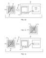
- FIG. 1is an isometric view of a typical AIMD fitted with a biocompatible enclosed RFID tag of the present invention.
- FIG. 2is an isometric view that isolates the header block of the AIMD shown in FIG. 1 and a close-up view ( FIG. 2A ) of the embedded RFID tag.
- FIG. 3is a depiction of a patient with an AIMD fitted with an RFID tag of the present invention and an external interrogator/reader.
- FIG. 4is a wire-formed diagram of the generic human body showing a number of active medical devices (AIMDs) and associated internal and external lead wires.
- AIMDsactive medical devices
- FIG. 5is an isometric view of a biocompatible and hermetically sealed container in accordance with the present invention.
- FIG. 6is a vertical cross-section of the biocompatible and hermetically sealed container taken along line 6 - 6 of FIG. 5 .
- FIG. 7Ais a horizontal cross-section of the biocompatible and hermetically sealed container taken along line 7 - 7 of FIG. 5 .
- FIG. 7Bis a horizontal cross-section of a square-shaped alternative of the biocompatible and hermetically sealed container taken along line 7 - 7 of FIG. 5 .
- FIG. 7Cis a horizontal cross-section of a rectangular alternative of the biocompatible and hermetically sealed container taken along line 7 - 7 of FIG. 5 .
- FIG. 7Dis a horizontal cross-section of an elliptical or oval alternative of the biocompatible and hermetically sealed container taken along line 7 - 7 of FIG. 5 .
- FIG. 8is a vertical cross-section of an alternative construction of the biocompatible and hermetically sealed container of the present invention.
- FIG. 9is a vertical cross-section of another alternative construction of the biocompatible and hermetically sealed container of the present invention.
- FIG. 10is a vertical cross-section of yet another alternative construction of the biocompatible and hermetically sealed container of the present invention.
- FIG. 11illustrates the assembly of the biocompatible and hermetically sealed container of the present invention including an X-ray identification tag.
- FIG. 12is an isometric view of an alternative tissue fixation end cap for use with the biocompatible and hermetically sealed container of the present invention.
- FIG. 13is a block diagram depicting operation of a system including the RFID tag of the present invention.
- FIG. 14is a top view of an RFID tag and antenna of the present invention.
- FIG. 15is a block diagram depicting operations of an alternative system including an RFID tag of the present invention.
- FIG. 16is a block diagram depicting operation of another alternative system including an RFID tag of the present invention.
- FIG. 17is a block diagram depicting operation of yet another alternative system including an RFID tag of the present invention.
- FIG. 18is an isometric view of an alternative embodiment of the biocompatible and hermetically sealed container of the present invention.
- FIG. 18Ais an isometric view of another alternative end cap for use with the biocompatible and hermetically sealed container of the present invention.
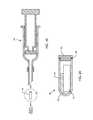
- FIG. 19is a cross-sectional view of a large needle syringe and biocompatible and hermetically sealed container of the present invention.
- FIG. 20an enlarged cross-sectional view of the encapsulated RFID tag in the biocompatible and hermetically sealed container depicted in FIG. 18 ;
- FIG. 21is a fragmented sectional view of a prior art unipolar hermetic terminal typically used in active implantable medical devices.
- FIG. 22is an enlarged, partially fragmented perspective view of the feedthrough capacitor shown in FIG. 20 .
- FIG. 23is a schematic electrical diagram of the coaxial feedthrough capacitor of FIG. 22 .
- FIG. 24illustrates various EMI attenuation curves for several different multi-element EMI filters.
- FIG. 25is a perspective view of a quadpolar feedthrough capacitor combined with a lossy ferrite inductor slab.
- FIG. 26is an enlarged sectional view taken generally along the line 26 - 26 of FIG. 25 .
- FIG. 27is a sectional view similar to FIG. 26 illustrating a quadpolar feedthrough filter terminal constructed in an LL configuration.
- FIG. 28is an electrical schematic diagram of the feedthrough terminal illustrated in FIG. 27 .
- FIG. 29is a perspective and somewhat schematic view of an active implantable medical device (AIMD) including lead wires directed to a heart of a patient, and an interrogator and access device for reading information from RFID tags associated with the lead wires or AIMD.
- AIMDactive implantable medical device
- FIG. 30is an enlarged view of a lead wire of FIG. 29 , illustrating the attachment of an RFID tag thereto.
- FIG. 31is an enlarged view similar to FIG. 30 , but illustrating another method of attachment of the RFID tag to the lead wire.
- FIG. 32is yet another enlarged view of an RFID tag attached to the lead wire.
- FIG. 33is a diagram of a unipolar active implantable medical device having RFID tags associated therewith.
- FIG. 34is a diagram similar to FIG. 33 , illustrating a bipolar AIMD system.
- FIG. 35is a diagram similar to FIGS. 33 and 34 , illustrating a bipolar lead wire system and a distal TIP and RING, typically used in a cardiac pacemaker.
- FIG. 36is a schematic diagram showing a parallel combination of an inductor L and a capacitor C forming a TANK or bandstop filter, which can be placed in the lead wire system of FIGS. 33-35 .
- FIG. 37is a schematic diagram similar to FIG. 36 , but illustrating an AIMD with multiple lead wires, each lead wire incorporating multiple TANK filters, in accordance with the present invention.
- the present inventionis directed to a radio frequency identification (RFID) system for use with active implantable medical devices (AIMDs) and implantable lead wire systems.
- RFIDradio frequency identification
- AIMDsactive implantable medical devices
- the RFID systemcomprises an RFID tag implanted in a patient's body and associated with an implanted AIMD or lead wire system, and an interrogator in communication with the RFID tag.
- FIG. 1is an isometric view of a typical AIMD 10 , such as a cardiac pacemaker.
- Cardiac pacemakerstypically have a metallic housing 18 which can be of titanium, stainless steel or the like.
- This metallic housing 18is laser welded shut and generally contains a hermetic feedthrough terminal 30 for passage of lead wires 32 into the interior of the metallic housing 18 .
- Said hermetic feedthrough terminals 30are well known in the art and are generally laser welded into the metallic housing 18 of the implantable medical device.
- the lead wires 32 as shown in FIG. 1are generally routed to connectors 34 .
- the connectors 34provide a convenient location to plug in the lead wires 32 which are routed to the heart for pacing and biologic sensing.
- the connector assembly 30 , 32 , 34is generally encapsulated within a molded non-metallic, i.e., plastic or ceramic, header block 36 , as shown.
- this header block 36is of clear casting materials which are well known in the art. Opaque thermal setting or chemically setting materials may also be used.
- FIG. 1there is an RFID tag 12 which has been cast into the header block 36 .
- suitable fixturesused to position the connectors 34 and RFID tag 12 during the casting of the header block 36 .
- the RFID tag 12 shown in FIG. 1may be enclosed within a biocompatible and hermetically sealed container 40 as will be described below.
- FIG. 2isolates the header block 36 of FIG. 1 with an RFID tag 12 embedded within the header block 36 .
- the RFID tag 12is not enclosed within a biocompatible and hermetically sealed container 40 .
- the RFID tag 12has a substrate 22 , an antenna or coil 14 , and an RFID chip 16 .
- the substrate 22may comprise single or multiple layers.
- the antenna 14is for both receiving electromagnetic energy to power the RFID chip 16 and for retransmitting a digital pulse. These devices are well known in the art.
- RFID standardsare evolving worldwide at various frequencies. For example, a 915 MHz protocol is generally evolving to be used for retail goods and inventory control. However, due to the high frequency, the 915 MHz protocols are not very useful for human implants. The reason for this is that humans are largely water and 915 MHz fields are greatly affected by the presence of water.
- the preferred embodimentis another RFID protocol which operates at 125 to 135 kHz or 13.56 MHz which is ideal for an implantable RFID tag. The 13.56 MHz lower frequency will readily penetrate and communicate with the tag instead of reflecting off of the skin surface or being absorbed. There are other lower frequency RFID systems, for example, in the 130 kHz range which would also be suitable.
- the RFID tag 12may be enclosed in a biocompatible and hermetically sealed container 40 , as shown in FIG. 5 and as will be described more fully below.
- FIGS. 1 and 2both show a non-hermetically sealed RFID tag 12 which is encapsulated within the molded header block of an AIMD such as a cardiac pacemaker.
- AIMDsuch as a cardiac pacemaker.
- molded header blocksare common in the industry and are designated by ISO Standards IS-1, DF-1 or IS-4 or the equivalent.
- These header blocks 36typically contain a connector system so that the medical practitioner can plug in lead wires for example those that would run from the pacemaker into the chambers of the heart.
- this header block materialis a solid encapsulated material such as an epoxy, thermal setting polymer or the like. In general such materials are not considered truly hermetic and will have leak rates varying from 10 ⁇ 5 to 10 ⁇ 6 cubic centimeters per second.
- body fluidswould eventually, due to the bulk permeability of the header block 36 material reach the electronic circuits of the RFID tag 12 .
- Body fluidsare comprised primarily of water and dissolved salts including sodium, chlorine, potassium, calcium and the like. These are ionic and if they reach the surfaces of the RFID tag 12 it will readily short it out.
- the RFID tag 12will be hermetically sealed.
- a short term medical implant device placement of the RFID chip within the header block 36would be acceptable. For example, the average life of most cardiac pacemakers is five to seven years.
- the hermetic seal characteristics of the header block assembly 36depend upon the ability of the molding or plastic materials of the header block 36 to prevent body fluids from penetrating to the RFID tag 12 . Penetration of body fluids over time to the RFID tag 12 may cause degradation of insulation resistance, or short circuits. Accordingly, hermetically encapsulating the RFID tag 12 , as will be described below, is the preferred embodiment.
- FIG. 3is an outline drawing of an adult male pacemaker patient with an AIMD 10 .
- FIG. 3shows a dashed ellipse which indicates one potential location for an AIMD 10 .
- the location shown in FIG. 1is typical of a right or left pectoral muscle implant.
- Right and left pectoral muscle implantsare typical for a cardiac pacemaker or implantable cardioverter defibrillator (ICD).
- ICDimplantable cardioverter defibrillator
- the right and left pectoral muscle regionis chosen due to the easy access to the subclavian veins for insertion of lead wires and electrodes down into the heart.
- the present inventionmay also find application in other AIMDs such as, an implantable defibrillator, a congestive heart failure device, a hearing implant, a cochlear implant, a neurostimulator, a drug pump, a ventricular assist device, a drug pump, a spinal cord stimulator, an implantable sensing system, a deep brain stimulator, an artificial heart, an incontinence device, a vagus nerve stimulator, a bone growth stimulator, a gastric pacemaker, or a prosthetic device.
- AIMDssuch as, an implantable defibrillator, a congestive heart failure device, a hearing implant, a cochlear implant, a neurostimulator, a drug pump, a ventricular assist device, a drug pump, a spinal cord stimulator, an implantable sensing system, a deep brain stimulator, an artificial heart, an incontinence device, a vagus nerve stimulator, a bone growth stimulator, a gastric pacemaker, or
- FIG. 4is a wire formed diagram of a generic human body showing a number of implanted medical devices.
- 10 Ais a family of external and implantable hearing devices which can include the group of hearing aids, cochlear implants, piezoelectric sound bridge transducers and the like.
- 10 Bincludes an entire variety of neurostimulators and brain stimulators. Neurostimulators are used to stimulate the Vagus nerve, for example, to treat epilepsy, obesity and depression.
- Brain stimulatorsare similar to a pacemaker-like device and include electrodes implanted deep into the brain for sensing the onset of the seizure and also providing electrical stimulation to brain tissue to prevent the seizure from actually happening.
- the lead wires that come from a deep brain stimulatorare often placed using real time imaging. Most commonly such lead wires are placed during real time MRI.
- 10 Cshows a cardiac pacemaker which is well-known in the art.
- 10 Dincludes the family of left ventricular assist devices (LVAD's), and artificial hearts, including the recently introduced artificial heart known as the Abiocor.
- 10 Eincludes an entire family of drug pumps which can be used for dispensing of insulin, chemotherapy drugs, pain medications and the like. Insulin pumps are evolving from passive devices to ones that have sensors and closed loop systems.
- 10 Fincludes a variety of external or implantable bone growth stimulators for rapid healing of fractures.
- 10 Gincludes urinary incontinence devices.
- 10 Hincludes the family of pain relief spinal cord stimulators and anti-tremor stimulators. 10 H also includes an entire family of other types of neurostimulators used to block pain.
- 10 Iincludes a family of implantable cardioverter defibrillators (ICD) devices and also includes the family of congestive heart failure devices (CHF). This is also known in the art as cardio resynchronization therapy devices, otherwise knows as CRT devices.
- 10 Jillustrates an externally worn pack.
- This packcould be an external insulin pump, an external drug pump, an external neurostimulator, a Holter monitor with skin electrodes or even a ventricular assist device power pack.
- 10 Killustrates the insertion of an external probe or catheter. These probes can be inserted into the femoral artery, for example, or in any other number of locations in the human body.
- an interrogator 20also known as a hand held scanner or reader.
- the interrogator 20transmits an electromagnetic field pulse 26 which is intercepted by the antenna 14 that is part of the implanted RFID tag 12 .
- the implanted RFID tag 12is generally passive. That means that it does not have its own self-contained source of energy such as a battery.
- the electromagnetic field 26 that comes from the interrogator 20resonates with the antenna 14 and RFID chip 16 providing energy for the RFID chip 16 to generate a signal and the antenna 14 to emit a return pulse 28 .
- This pulse 28is picked up by an antenna 14 in the interrogator 20 .
- the pulse 28contains digital modulation.
- this digital modulationcan contain information such as the model number of the patient's AIMD, the serial number of the AIMD, the manufacturer of the lead wire system, the name of patient's physician, and contact information for the physician.
- the digital pulsecan also contain the patient's name, the patient's medical condition, the patient's address and telephone number, and other pertinent information.
- FIG. 5is an isometric view of a biocompatible and hermetically sealed container 40 in accordance with the present invention.
- This hermetically sealed container 40is designed to encase the RFID tag 12 .
- the RFID tag 12is generally constructed of materials that are not long term biocompatible and body fluid resistant, it is important to prevent body fluids from reaching the RFID tag 12 . Even if the RFID tag 12 is embedded deeply within a molded polymer header block 36 as illustrated in FIG. 2 , when such a device is implanted into body tissue for many years (cochlear implants may last forty years or longer), moisture can slowly penetrate due to the bulk permeability of the polymer material of the header block 36 .
- the RFID chipbe completely hermetically sealed with a maximum leak rate of 1 ⁇ 10 ⁇ 7 cubic centimeters per second.
- hermetically sealedmeans a leak rate of 10 ⁇ 7 cubic centimeters per second or slower.
- a maximum leak rate of not more than 1 ⁇ 10 ⁇ 12 cubic centimeters per secondis ideal. This is in sharp contrast to prior art polymer fill systems which achieve at most a leak rate of around 1 ⁇ 10 ⁇ 5 cubic centimeters per second, and are not considered hermetic seals in accordance with the present invention.
- the RFID tag 12has been placed inside the biocompatible and hermetically sealed container 40 .
- This sealed container 40has an extruded, machined, or pressed ceramic housing 42 . It is not possible to make the entire sealed container 40 out of a metal such as titanium because this would shield the RFID tag 12 from the electromagnetic field from the interrogator 20 . In other words, if the RFID tag 12 was placed inside the titanium housing of an AIMD 10 , this would shield the radio frequency pulses. This would completely prevent the RFID tag 12 from receiving energy or sending out any pulses. Accordingly, the ceramic housing 42 as indicated in FIGS. 5 and 6 , allows electromagnetic fields to freely pass to and from the RFID tag 12 .
- the ceramic housing 42 as shown in FIG. 6is formed by ceramic manufacturing operations that are well known in the art. This generally consists of taking pure alumina ceramic powders, formulating them with a binder system and pressing them into the desired shape. This is then fired or sintered at very high temperature which makes a very hard structure.
- the housing 42is hermetically sealed using an end cap 44 that covers an open end of the housing 42 .
- the end cap 44is constructed from titanium but may also be ceramic.
- the ceramic housing 42is first selectively metallized using a sputtering technique. A preferred methodology would be to sputter a titanium-molybdenum composition 46 which is suitable for wetting a gold braze joint 48 .
- the gold brazed joint 48is used to make a metallurgical hermetic connection between the end cap 44 and the ceramic housing 42 .
- the RFID tag 12is in an encapsulant 50 so that it will not rattle around or vibrate inside the overall sealed container 40 .
- encapsulant 50can be of a variety of non-conductive materials, including thermal-setting nonconductive polymers, silicones and the like.
- desiccant material 51that is placed inside the device as a moisture getter.
- the hermetic terminal for ingress and egress of lead wires through the devicecan have a leak rate of from 10 ⁇ 7 to 10 ⁇ 9 cubic centimeters per second. This allows a certain amount of moisture to penetrate over a period of years. In other words, when a small amount of moisture enters into a relatively large available space, droplets or moisture thin films will not typically be formed. The moisture will disburse and will gradually raise what is called the residual moisture (humidity) level inside the device. The residual moisture level typically starts at zero and will slowly climb over the life of the device to around 8%. However, in a relatively tiny hermetically sealed space as shown in the hermetically sealed enclosure of FIG. 6 there is much less available free air space.
- the hermetic seal that is formed with gold braze 48 in the enclosure in FIG. 6preferably would have a lower leak rate.
- these deviceswill be tested to a leak rate of no more than 1 ⁇ 10 ⁇ 12 cubic centimeters per second. This means that much less moisture will penetrate the device and there will be much less chance for a moisture thin film or droplet to form on the sensitive electronic circuits.
- the desiccant material 51has been added as a safety mechanism such that hermetic terminals having a leak rate in the approximate range of 1 ⁇ 10 ⁇ 7 to 1 ⁇ 10 ⁇ 9 cubic centimeters per second can be safely used.
- Desiccantsare generally well known in the prior art and can include anhydrous magnesium and calcium sulfate. Also activated silica gels are commonly used. Other acceptable desiccants include molecular sieves, montmorillonite clay activated carbons and synthetic sodium aluminosilicate. All of these desiccants have a very strong affinity for water and also absorb moisture mounting to more than 20% of their original weight.
- FIGS. 7A-7Dshow cross-sectional views of various alternative shapes for the ceramic housing 42 and end cap 44 previously described in FIG. 6 .
- FIG. 7Ais a round cross-section, which is identical to that previously shown in FIG. 6 .
- An alternative square cross-sectionis shown in FIG. 7B .
- a rectangular cross-sectionis shown in FIG. 7C .
- An elliptical or oval cross-sectionis shown in FIG. 7D . All the configurations and others will be apparent to those skilled in the art.
- FIG. 8is a very similar biocompatible and hermetic sealed container 40 as previously described in FIGS. 6 and 7 ; however, in this case, the ceramic housing 42 is open at both ends and two end caps 44 hermetically seal the container 40 .
- the reason for thisis that the ceramic housing 42 may be extruded in a continuous operation and then blade cut. This could make the ceramic housing 42 much less expensive than the closed end housing 42 previously shown in FIG. 6 .
- a negative of the assembly as described in FIG. 8is that there are two end caps 44 which must be gold brazed or welded 48 to the ceramic housing 42 . Accordingly, there must be two circumferential or perimeter metallized bands 46 of the ceramic housing 42 so that the gold braze 48 will wet and form a hermetic seal. It is a matter of manufacturing cost trade-offs whether to use the single end cap 44 assembly as described in FIG. 6 or the dual end cap 44 assembly as shown in FIG. 8 .
- the end caps 44may be of titanium, stainless steel, tantalum, niobium or other suitable biocompatible metallic material.
- ceramic materialsthat may be used for the end cap 44 , including alumina ceramic and the like.
- a ceramic end cap 44may also have to be selectively metallized 46 by sputtering, plating, vapor deposition or the like.
- alternative materialsthat may be used for the hermetic housings 42 as described herein. These include all ceramics, glasses, sapphire, porcelain, polymer composites and the like.
- FIG. 9is an alternative method of installation of an end cap 44 wherein the end cap 44 is placed inside of the ceramic housing 42 .
- FIG. 10is yet another method of having a step titanium end cap 44 with a gold braze joint 48 between the butt ends of the ceramic housing 42 and the step of the end cap 44 .
- a novel hole 58convenient for placing a suture. This could be used to affix the hermetically sealed RFID tag to any point within the human body.
- This suture hole 58can also be used to affix the RFID tag to an active or abandoned lead wire system. This is important for the purposes of identifying the type of lead wire system and its compatibility with certain medical diagnostic procedures, such as certain types of MRI systems.
- FIG. 11is an exploded view of the sealed container 40 of FIGS. 5 and 6 .
- the RFID tag 12is positioned for insertion into the ceramic housing 42 .
- a gold braze pre-form 48 ais positioned near the joint of the end cap 44 and the ceramic housing 42 as shown.
- An optional X-ray identification tag 52may also be affixed to the sealed container 40 with more gold braze pre-forms 54 , as shown.
- the gold braze pre-forms 48 a and 54are re-flowed in a vacuum brazing furnace.
- the gold braze pre-form 48 aseals the end cap 44 to the ceramic housing 42 and the one or more gold braze pre-forms 54 attach the X-ray identification tag 52 to the ceramic housing 42 .
- Low temperature brazesare preferred so as not to cause thermal damage to the RFID tag.
- the ceramic housing 42is selectively metallized 46 using sputtering or equivalent techniques prior to placement in the vacuum brazing furnace so that the gold braze pre-forms 48 a and 54 will wet to the ceramic tube 42 .
- Suitable low temperature brazesinclude Ti—Cu—SiI, Cu—SiI and the like.
- X-ray identification tags 52are well known in the art for encapsulating with pacemaker and ICD header blocks. The reason for the X-ray identification tag 52 is so that a physician can read a patient chest X-ray and obtain valuable information such as pacemaker model number and manufacturer. Having a redundant identification system like this is desirable in the very unlikely event that the RFID tag 12 should fail to operate.
- FIG. 12is a novel end cap 44 that is formed with a fixation hole comprising a post 56 and a loop 58 .
- This end cap 44is designed so that a surgeon can put a suture or stitch through the loop 58 and affix the container 40 to body tissue. This is very important in cases where a container 40 is to be implanted adjacent to a prosthetic device or outside of the AIMD 10 .
- Certain AIMDs 10such as deep brain or neurostimulators, are simply too small or do not have a header block 36 into which to encapsulate or capture the container 40 .
- a loop 58 as shown in FIG. 12allows a convenient location for the physician to stitch and fixate the container 40 .
- the hole feature 58as shown in FIG.
- feature 58can also be used to affix any of the embodiments of the present invention to active or abandoned lead wire systems for AIMDs, as will be more fully discussed below.
- the container 40is about the size of two grains of rice. Accordingly, if the container 40 were simply placed into the body without fixation, it could migrate through muscle or other tissues. This would make it very difficult to locate for purpose of use or if it was later desired to remove it.
- FIGS. 13 , 14 and 15depict block diagrams of the RFID system in operation.
- the RFID tag 12consists of a substrate 22 , an RFID chip 16 , and an antenna 14 .
- the interrogator 20 with associated antenna 24discharges electromagnetic energy 26 to the antenna 14 of the RFID tag 12 , which powers up the RFID chip 16 and allows it to produce the electromagnetic return signal 28 , as shown.
- the electromagnetic return signal 28is detected by the interrogator 20 and presented as a digital code sequence.
- the RFID tag 12may be read-only (RO) or read/write (RW). With an RW RFID tag 12 , a physician may use an external programmer or interrogator 20 to write additional patient information to the RFID tag 12 . This additional information may include patient name, patient address, medical condition, and so on.
- the RFID tag 12In the case of an RO RFID tag 12 , the RFID tag 12 would be installed at the time of AIMD manufacture and would designate manufacturer, model number and other key information. However, an RO RFID tag 12 would not be later programmable and could not include added important information such as patient name, doctor name, patient diagnosis and so forth.
- the interrogator 20may comprise programmer or programmer/reader, which would permit direct display of all of the information contained on the RFID tag 12 .
- FIG. 16illustrates a very similar system as previously described in FIGS. 13 , 14 and 15 except that the interrogator 20 is designed to be integrated with a computer system 60 which may be linked to the worldwide web.
- a unique digital number transmitted by the RFID tag 12may be entered into the computer system 60 .
- the computer system 60maintains a database of important information that is all keyed to the digital information transmitted by the RFID tag 12 .
- the physician or emergency room personnelmay obtain the digital code from the RFID tag 12 which enters automatically (or manually) into the computer system 60 to immediately get a download, including all of the information required as to the model and serial number of the AIMD, lead wire system, patient and physician information, and patient history when available.
- ACC-NCDRAmerican College of Cardiology National Cardiovascular Data Registry
- CathPCI Registrythe CarotidStent Registry
- ICD RegistryThe ICD Registry was developed in partnership with the Heart Rhythm Society and is designed for participation by hospitals. It collects detailed information on ICD implantations and has as one of its missions helping hospitals meet regulatory requirements and Medicare requirements.
- FIG. 17illustrates a system very similar to that described in FIG. 16 except that the output of the interrogator 20 would go to an antenna and processor 38 which are designed to be linked directly to a laptop computer 62 . This could also be done by USB or equivalent cable interface network 72 .
- the laptop computer 62may contain a full database by model numbers and serial numbers of medical implantable devices. A drawback to this type of system is that it would be very difficult to keep updated with current patient and physician information.
- FIG. 18is an isometric view of the RFID tag 12 that was previously described in FIGS. 5 and 6 , but has been modified in accordance with the end cap 44 described in FIG. 12 .
- the titanium end cap 44includes a loop 58 to fix in body tissue or affix to an active or abandoned lead wire set.
- the metallization 46 on the ceramic housing 42 and the braze 48forms a hermetic seal.
- the style of post 56 and loop 58 depictedis just one type one with ordinary skill in the art will recognize.
- FIG. 18Ashows another embodiment. It will be obvious to those skilled in the art that loops 58 may also be placed directly on the ceramic housing 42 itself.
- FIG. 19illustrates a large needle syringe 70 designed for injecting the RFID tag container 40 directly into body tissue.
- the sealed container 40has an end cap 44 that is designed to make a smooth transition from the ceramic housing 42 to the end cap 44 . This makes the container 40 suitable for injection into body tissue. As previously mentioned, a negative to this approach is that the container 40 may tend to migrate over time within the body tissue.
- FIG. 20is an exploded view taken from FIG. 19 illustrating a cross-section of the container 40 .
- the titanium end cap 44has been butted onto and brazed 48 to the ceramic tube 42 such that it forms a smooth outer surface.
- FIG. 21illustrates a prior art unipolar hermetic terminal 80 typically used in active implantable medical devices.
- Hermetic terminalsconsist of an alumina insulator 82 which is gold brazed 84 to a ferrule 86 .
- the ferruleis typically laser welded 88 to the titanium housing 90 of an active implantable medical device.
- Such feedthrough capacitors 96are well known in the prior art for decoupling and shielding against undesirable electromagnetic interference (EMI) signals, such as those produced by cellular telephones, microwave ovens and the like. See, for example, U.S. Pat. Nos. 4,424,551; 5,333,095; 5,905,627; 6,275,369; 6,566,978 and 6,765,779.
- EMIelectromagnetic interference
- FIG. 22is a partial cutaway view showing the details of the prior art feedthrough capacitor 96 as previously illustrated in FIG. 21 .
- Electrode plate set 100is known as the ground electrode plate set and is coupled to the capacitor's outside diameter metallization 102 .
- the active electrode plate set 98is electrically connected to the capacitor inside diameter metallization 104 .
- FIG. 23is a schematic diagram of the prior art feedthrough capacitor 96 illustrated in FIGS. 21 and 22 .
- the present inventionresides in RFID readers and systems in order to interrogate and identify an active implantable medical device.
- the RFID fieldIn order for the RFID field to be able to read a tag embedded within the human body, it must generate a very powerful yet relatively low frequency field.
- the preferred embodimentis a 125 to 135 kHz or 13.56 MHz HF reader. Such readers are most effective when held within 10 centimeters of the implant. In general, these are 3 to 6-watt effective radiated power (ERP) devices.
- ERPeffective radiated power
- a cellular telephone which produces a very powerful near fieldis only a 0.6 to 2-watt ERP devices. Accordingly, the patient with an active implantable medical device is subjected to a very powerful digitally pulsed RFID reader field.
- the AIMDhave very robust shielding and filtering against the electromagnetic interference that is being produced by the RFID reader itself. This is in order to assure that the electronics of the AIMD are not subjected to temporary or permanent malfunction. Instances of pacemaker inhibition, microprocessor reset or even permanent damage to device electronics have all been documented in the past due to EMI. Accordingly, there is a need in combination with the present invention for the AIMD to be particularly robust so it will be resistant to the fields produced by the RFID reader.
- PC69defines electromagnetic compatibility test requirements for pacemakers and implantable defibrillators. It specifically has a radiated dipole test with a mandatory requirement that the AIMD be resistant when the dipole has 40 milliwatts of net input power. There is also an optional or voluntary test level which is at 8 watts (and 2 watts at certain higher frequencies). PC69 currently covers the frequency range from 450 MHz to 3 GHz which is, of course, above the range of the preferred embodiment 13.56 MHz RFID readers. Because of this, AIMDs tend to use relatively low value feedthrough capacitors as illustrated in FIGS. 21 and 22 . Such feedthrough capacitance values, for example, can be as low as 300 picofarads and still comply with the mandatory 40-milliwatt level.
- pacemakersthat do not have a feedthrough capacitor EMI filter to comply with the optional 8-watt level can respond to the signals from RFID readers.
- Periods of noise sensing, inhibition and misbeatswere documented in pacemakers out to a distance of 21 centimeters. This is the distance between the pacemaker placed in a saline tank and a portable RFID reader.
- FIG. 24A better way to approach this is illustrated in FIG. 24 and is more fully described in co-pending patent application, Ser. No. 11/097,999 and U.S. Pat. No. 6,999,818, the contents of which are incorporated herein.
- FIG. 24one can see that the prior art feedthrough capacitors “C” have an attenuation slope shown as C. The average attenuation slope rate for this is only 20 dB per decade.
- additional series elementssuch as inductive and resistive elements, one can greatly increase the attenuation slope rate of the EMI filter. For example, referring to the L 1 or L 2 curve of FIG.
- FIGS. 25 and 26illustrate a quadpolar feedthrough capacitor 96 which is combined with a lossy ferrite inductor slab 106 .
- Thisallows the designer to use a relatively low value of capacitance such that it does not load down the output of the AIMD or degrade biologic sensing signals, but at the same time by adding the inductor element, offers a filter with a very high degree of RF immunity. In this way, one can comply with the optional 8-watt level of PC69 and provide immunity to closely held RFID tag readers while not overloading the AIMD circuitry. Too much capacitance on the output of the AIMD also tends to lower its input impedance at MRI RF pulsed frequencies. Accordingly, it is important that the capacitance value also be kept low for this reason.
- FIGS. 27 and 28show a terminal 80 in an LL 1 configuration. Referring once again to FIG. 24 , one can see that this has an attenuation slope rate of 80 dB per decade which is extremely robust. In point of fact, in combination with the present invention such that the AIMD be resistant to RFID readers in the preferred embodiment, the EMI filter circuit would be modified to be of the L, T or LL configuration.
- FIG. 29a diagrammatic view of an active medical device 10 , such as a cardiac pacemaker or the like, is shown implanted within a patient, and having lead wires 110 and 112 extending therefrom and to a point in the patient's body 114 necessary to receive signals, apply electrical shock or other therapy, and the like as is known in the art.
- the lead wires 110 and 112comprising the lead wire system extend from the active implanted medical device 10 into the heart 116 of the patient 114 .
- lead wires 110 and 112are operably connected to an AIMD 10 , or the AIMD 10 has been removed and the lead wires 110 and 112 abandoned within the patient 114 .
- a physicianmay be able to palpitate the patient 114 in an emergency situation and determine the presence of an active implantable medical device 10 , such is usually not the case with abandoned lead wires 110 and 112 .
- RFID tags 12are associated with the one or more lead wires 110 and 112 , so as to identify the presence of the lead wires 110 and 112 when a reader or interrogator 20 is brought in to sufficiently close proximity thereto.
- the interrogator or reader 20may be operably coupled to an access or reading device, such as a computer 62 , which can visually, or otherwise, relay information to the physician, access databases to retrieve patient information, and the like.
- the RFID chip within the RFID tag 12preferably includes information about the patient, the AIMD 10 , and/or the lead wires 110 and 112 .
- the RFID tag 12can store and transmit the patient's name and date of birth, the patient hospital identification number or physician name, and medical history.
- the name and phone number of the implanting physicianis given.
- the implant date and the hospitalare also preferably given.
- information regarding the implanted device 10 , the lead wire model numbers or serial numbers, and the lead wire positionsare also provided.
- the defibrillation energy, HV impedance (ohms), P/R Waive amplitude slew rate, pacing threshold, pulse pacing width, pacing impedance (ohms), threshold current (ma), and other such informationmay also be stored on the RFID tag for assisting the physician in determining treatment parameters.
- Merely knowing about the presence of the lead wires 110 and 112 , and/or the implantable medical device 10also alerts the physician to the limitations of conducting an MRI on the patient.
- the RFID tag 12can also be directly attached to the lead wire 110 or 112 , or formed as a part thereof during the manufacture of the lead wire.
- the RFID tag 12is disposed within a hermetically sealed encapsulant material or the like 118 which is fixed to the exterior of the lead wire 110 , as illustrated in FIG. 30 .
- the RFID tag 12may also be disposed within the insulation 120 surrounding the lead wire 110 so as to be disposed between the conductive wire 122 and the outer insulated sheet 120 , as illustrated in FIG. 31 .
- the RFID tag 12may be placed within a hermetically sealed container 124 which is attached to the lead wire 110 , such as by the crimped clamp device 126 illustrated in FIG. 32 .
- the container 124could be in the form of container 40 , described above, with a suture or other connecting means attaching the container 40 , with the RFID tag 12 therein, to the lead wire 110 .
- FIG. 33is a general diagram of a unipolar active implantable medical device system 10 .
- FIG. 33could also be representative of an externally worn medical device such as a Holter monitor.
- the distal electrode 128would typically be a scan or patch electrode.
- the housing 18 of the active implantable medical device 10is typically titanium, ceramic, stainless steel or the like. Inside of the device housing are the AIMD electronic circuits.
- AIMDsinclude a battery, but that is not always the case. For example, for a Bion, it can receive its energy from an external pulsing magnetic field.
- a lead wire 110is routed from the AIMD 10 to a point 128 where it is embedded in or affixed to body tissue.
- the distal TIP 128could be in the spinal cord.
- the distal electrode 128would be placed deep into the brain, etc.
- the distal electrode 128would typically be placed in the cardiac right ventricle.
- FIG. 34is very similar to FIG. 33 except that it is a bipolar system.
- the electric circuit return pathis between the two distal electrodes 128 and 130 ′.
- thiswould be known as a bipolar lead wire system with one of the electrodes known as the distal TIP 132 and the other electrode which would float in the blood pool known as the RING 134 (see FIG. 35 ).
- the electrical return path in FIG. 33is between the distal electrode 128 through body tissue to the conductive housing 18 of the implantable medical device 10 .
- the patientcould be exposed to the fields of an MRI scanner or other powerful emitter used during a medical diagnostic procedure.
- Currents that are directly induced in the lead wire system 110can cause heating by I 2 R losses in the lead wire system or by heating caused by current flowing in body tissue. If these currents become excessive, the associated heating can cause damage or even destructive ablation to body tissue.
- the distal TIP 132is designed to be implanted into or affixed to the actual myocardial tissue of the heart.
- the RING 134is designed to float in the blood pool. Because the blood is flowing and is thermally conductive, the RING 134 structure is substantially cooled. In theory, however, if the lead curves, the RING 134 could also touch and become encapsulated by body tissue.
- the distal TIP 132is always thermally insulated by surrounding body tissue and can readily heat up due to the RF pulse currents of an MRI field.
- RFID tags 12are associated with at least the AIMD 10 or a lead wire 110 extending therefrom.
- an RFID tagis associated with both the AIMD 10 as well as all lead wires 110 , etc. extending therefrom.
- the physiciancan interrogate the RFID tag 12 and be provided information regarding the AIMD 10 , lead wire system, patient, etc.
- a tank filter, or bandstop filteris associated with the AIMD 10 and lead wire system 110 such that the presence of the MRI signal or static field does not heat up the lead wires 110 , 112 , etc. leading to tissue damage or damage to the implantable device, sensors, lead systems, etc.
- FIG. 36is a schematic diagram showing a parallel combination of an inductor L and a capacitor C to be placed in the lead wire systems 110 previously described. This combination forms a parallel tank circuit or bandstop filter 136 which will resonate at a particular frequency (f r ).
- U.S. patent application Ser. No. 11/558,349discloses various tank filter structures and applications, any of which can be incorporated into the present invention.
- the general principle behind all of the tank or bandstop filter structuresis the parallel combination of an inductor L and a capacitor C having values selected such that the filter 136 resonates at the particular frequency of the pulsed RF field associated with the MRI.
- the bandstop filter 136is illustrated as being between the AIMD and the distal electrode inserted into the body tissue.
- the tank filter 136can be placed immediately adjacent to the AIMD, immediately adjacent to the distal electrodes 128 , or anywhere along the length of the lead wire 110 therebetween.
- multiple tank filters 136can be implemented such that one tank filter 136 is disposed adjacent to the AIMD 10 , and the other adjacent to the distal electrode 128 .
- the tank filterwill resonate at a particular MRI frequency, rendering the AIMD and lead wire system (whether associated with an AIMD or abandoned) compatible with that particular MRI frequency.
- This informationis included in the RFID tag 12 , so that the physician will know that the patient can have an MRI at that frequency even though there are implantable lead wires 110 , 112 .
- MRI systemsvary in static field strength from 0.5 Tesla all the way up to 3 Tesla with newer research machines going much higher. This is the force of the main static magnetic field.
- the frequency of the pulsed RF field associated with MRIis found by multiplying the static field in Tesla times 42.45. Accordingly, a 3 Tesla MRI system has a pulsed RF field of approximately 128 MHz. If the values of the inductor L and the capacitor C are selected properly, one could obtain a parallel tank resonant frequency of 128 MHz. For a 1.5 Tesla MRI system, the RF pulse frequency is 64 MHz.
- FIG. 37is the bipolar system of FIG. 34 redrawn to show two bandstop filters 136 in each lead wire 110 , 112 ′.
- F r1consisting of L 1 and C 1 in both of the bipolar lead wires 110 , 112 ′, which is designed to resonate at one selected frequency. For example, for a 1.5 Tesla MRI system, this would be 64 MHz.
- F r2consist of L 2 , C 2 parallel inductor capacitor combinations. For example, these could be designed for operation in a 3 Tesla MRI system and would therefore be designed to resonate at 128 MHz.
- bandstop filters, or tank filters, 136which can be utilized so as to make the lead wire system and AIMD compatible with different MRI systems.
- the trade off hereis that the distal electrodes 128 , 130 ′ would be physically elongated due to the additional components necessary.
- the RFID tags 12which are preferably associated with each lead wire 110 , 112 , etc., but at a minimum associated with the entire lead wire system, includes information relating to the bandstop or tank filters incorporated in the lead system and thus the MRI compatibility of the lead wire system.
- the physician and emergency health care personnelcan determine the presence of implanted medical devices 10 , the presence of active or abandoned lead wire systems, and their compatibility, if any, with MRI systems. This can be done in a fairly quick manner so that the proper diagnosis and treatment, which may include MRI scans, can be given by the physician.
Landscapes
- Health & Medical Sciences (AREA)
- Life Sciences & Earth Sciences (AREA)
- Veterinary Medicine (AREA)
- General Health & Medical Sciences (AREA)
- Engineering & Computer Science (AREA)
- Biomedical Technology (AREA)
- Nuclear Medicine, Radiotherapy & Molecular Imaging (AREA)
- Public Health (AREA)
- Animal Behavior & Ethology (AREA)
- Radiology & Medical Imaging (AREA)
- Heart & Thoracic Surgery (AREA)
- Surgery (AREA)
- Physics & Mathematics (AREA)
- Electromagnetism (AREA)
- Oral & Maxillofacial Surgery (AREA)
- Pathology (AREA)
- Medical Informatics (AREA)
- Molecular Biology (AREA)
- Acoustics & Sound (AREA)
- Vascular Medicine (AREA)
- Cardiology (AREA)
- Biophysics (AREA)
- Neurology (AREA)
- Electrotherapy Devices (AREA)
- Prostheses (AREA)
Abstract
Description
- associating a radio frequency identification (RFID) tag with a lead wire system for an active implantable medical device (AIMD), the RFID tag being readable/writable and having retrievable information relating to the AIMD;
- remotely interrogating the RFID tag to retrieve information relating to the AIMD and the lead wire system; and
- re-writing the retrievable information on the RFID tag when the lead wire system becomes associated with a replacement AIMD.
Claims (39)
Priority Applications (5)
| Application Number | Priority Date | Filing Date | Title |
|---|---|---|---|
| US11/943,470US7787958B2 (en) | 2001-04-13 | 2007-11-20 | RFID detection and identification system for implantable medical lead systems |
| EP08020056AEP2062525A3 (en) | 2007-11-20 | 2008-11-18 | RFID detection and identification system for implantable medical lead systems |
| US12/845,559US7983763B2 (en) | 2007-11-20 | 2010-07-28 | Implanted lead sleeve having RFID tag |
| US12/871,201US8321032B2 (en) | 2006-11-09 | 2010-08-30 | RFID-enabled AIMD programmer system for identifying MRI compatibility of implanted leads |
| US12/871,016US8326435B2 (en) | 2005-03-21 | 2010-08-30 | RFID detection and identification system for implantable medical lead systems |
Applications Claiming Priority (9)
| Application Number | Priority Date | Filing Date | Title |
|---|---|---|---|
| US28372501P | 2001-04-13 | 2001-04-13 | |
| US10/123,534US7844319B2 (en) | 1998-11-04 | 2002-04-15 | Systems and methods for magnetic-resonance-guided interventional procedures |
| US59423005P | 2005-03-21 | 2005-03-21 | |
| US59712505P | 2005-11-11 | 2005-11-11 | |
| US11/307,145US7916013B2 (en) | 2005-03-21 | 2006-01-25 | RFID detection and identification system for implantable medical devices |
| US80367206P | 2006-06-01 | 2006-06-01 | |
| US11/423,073US8244370B2 (en) | 2001-04-13 | 2006-06-08 | Band stop filter employing a capacitor and an inductor tank circuit to enhance MRI compatibility of active medical devices |
| US11/558,349US7945322B2 (en) | 2005-11-11 | 2006-11-09 | Tank filters placed in series with the lead wires or circuits of active medical devices to enhance MRI compatibility |
| US11/943,470US7787958B2 (en) | 2001-04-13 | 2007-11-20 | RFID detection and identification system for implantable medical lead systems |
Related Parent Applications (3)
| Application Number | Title | Priority Date | Filing Date |
|---|---|---|---|
| US11/307,145Continuation-In-PartUS7916013B2 (en) | 2001-04-13 | 2006-01-25 | RFID detection and identification system for implantable medical devices |
| US11/558,349Continuation-In-PartUS7945322B2 (en) | 1998-11-04 | 2006-11-09 | Tank filters placed in series with the lead wires or circuits of active medical devices to enhance MRI compatibility |
| US12/719,630Continuation-In-PartUS8761895B2 (en) | 2006-11-09 | 2010-03-08 | RF activated AIMD telemetry transceiver |
Related Child Applications (3)
| Application Number | Title | Priority Date | Filing Date |
|---|---|---|---|
| US12/845,559Continuation-In-PartUS7983763B2 (en) | 2007-11-20 | 2010-07-28 | Implanted lead sleeve having RFID tag |
| US12/871,016ContinuationUS8326435B2 (en) | 2005-03-21 | 2010-08-30 | RFID detection and identification system for implantable medical lead systems |
| US12/871,201Continuation-In-PartUS8321032B2 (en) | 2006-11-09 | 2010-08-30 | RFID-enabled AIMD programmer system for identifying MRI compatibility of implanted leads |
Publications (2)
| Publication Number | Publication Date |
|---|---|
| US20080065181A1 US20080065181A1 (en) | 2008-03-13 |
| US7787958B2true US7787958B2 (en) | 2010-08-31 |
Family
ID=40347896
Family Applications (2)
| Application Number | Title | Priority Date | Filing Date |
|---|---|---|---|
| US11/943,470Expired - Fee RelatedUS7787958B2 (en) | 2001-04-13 | 2007-11-20 | RFID detection and identification system for implantable medical lead systems |
| US12/871,016Expired - Fee RelatedUS8326435B2 (en) | 2005-03-21 | 2010-08-30 | RFID detection and identification system for implantable medical lead systems |
Family Applications After (1)
| Application Number | Title | Priority Date | Filing Date |
|---|---|---|---|
| US12/871,016Expired - Fee RelatedUS8326435B2 (en) | 2005-03-21 | 2010-08-30 | RFID detection and identification system for implantable medical lead systems |
Country Status (2)
| Country | Link |
|---|---|
| US (2) | US7787958B2 (en) |
| EP (1) | EP2062525A3 (en) |
Cited By (62)
| Publication number | Priority date | Publication date | Assignee | Title |
|---|---|---|---|---|
| US20080039709A1 (en)* | 2004-08-09 | 2008-02-14 | Karmarkar Parag V | Implantable Mri compatible Stimulation Leads And Antennas And Related Systems And Methods |
| US20080097193A1 (en)* | 2004-07-27 | 2008-04-24 | Karmarkar Parag V | Mri Systems Having Mri Compatible Universal Delivery Cannulas With Cooperating Mri Antenna Probes and Related Systems and Methods |
| US20080119919A1 (en)* | 2001-04-13 | 2008-05-22 | Surgi-Vision, Inc. | Mri compatible medical leads with band stop filters |
| US20080177267A1 (en)* | 2007-01-19 | 2008-07-24 | Sands Daniel L | Retrofit clamp with rfid tag for a surgical tool |
| US20080243218A1 (en)* | 2007-03-19 | 2008-10-02 | Bottomley Paul A | Mri and rf compatible leads and related methods of operating and fabricating leads |
| US20080262584A1 (en)* | 2007-03-19 | 2008-10-23 | Bottomley Paul A | Methods and apparatus for fabricating leads with conductors and related flexible lead configurations |
| US20090171421A1 (en)* | 2005-10-21 | 2009-07-02 | Ergin Atalar | Mri-safe high impedance lead systems |
| US20090234368A1 (en)* | 2008-03-17 | 2009-09-17 | Brian Gore | Low profile medical devices with internal drive shafts that cooperate with releasably engageable drive tools and related methods |
| US20100171596A1 (en)* | 2008-12-31 | 2010-07-08 | Burke Peter J | In vivo rfid chip |
| US20110004275A1 (en)* | 2009-07-06 | 2011-01-06 | Boston Scientific Neuromodulation Corporation | External Device for an Implantable Medical System Having Accessible Contraindication Information |
| US20110218422A1 (en)* | 2005-05-04 | 2011-09-08 | Surgivision, Inc. | Electrical lead for an electronic device such as an implantable device |
| US8219208B2 (en) | 2001-04-13 | 2012-07-10 | Greatbatch Ltd. | Frequency selective passive component networks for active implantable medical devices utilizing an energy dissipating surface |
| US20120212328A1 (en)* | 2008-10-28 | 2012-08-23 | Rf Surgical Systems, Inc. | Method and apparatus to detect transponder tagged objects, for example during medical procedures |
| US8275466B2 (en) | 2006-06-08 | 2012-09-25 | Greatbatch Ltd. | Band stop filter employing a capacitor and an inductor tank circuit to enhance MRI compatibility of active medical devices |
| US8326435B2 (en) | 2005-03-21 | 2012-12-04 | Greatbatch Ltd. | RFID detection and identification system for implantable medical lead systems |
| US8761717B1 (en) | 2012-08-07 | 2014-06-24 | Brian K. Buchheit | Safety feature to disable an electronic device when a wireless implantable medical device (IMD) is proximate |
| US9636509B2 (en) | 2012-01-27 | 2017-05-02 | Medtronic, Inc. | Retrieval of information from an implantable medical device |
| US9801566B2 (en) | 2007-02-19 | 2017-10-31 | Medtronic Navigation, Inc. | Automatic identification of instruments used with a surgical navigation system |
| US10016220B2 (en) | 2011-11-01 | 2018-07-10 | Nuvasive Specialized Orthopedics, Inc. | Adjustable magnetic devices and methods of using same |
| US10039661B2 (en) | 2006-10-20 | 2018-08-07 | Nuvasive Specialized Orthopedics, Inc. | Adjustable implant and method of use |
| US10238427B2 (en) | 2015-02-19 | 2019-03-26 | Nuvasive Specialized Orthopedics, Inc. | Systems and methods for vertebral adjustment |
| US10271885B2 (en) | 2014-12-26 | 2019-04-30 | Nuvasive Specialized Orthopedics, Inc. | Systems and methods for distraction |
| US10349995B2 (en) | 2007-10-30 | 2019-07-16 | Nuvasive Specialized Orthopedics, Inc. | Skeletal manipulation method |
| US10405891B2 (en) | 2010-08-09 | 2019-09-10 | Nuvasive Specialized Orthopedics, Inc. | Maintenance feature in magnetic implant |
| US10478232B2 (en) | 2009-04-29 | 2019-11-19 | Nuvasive Specialized Orthopedics, Inc. | Interspinous process device and method |
| WO2019222139A1 (en)* | 2018-05-14 | 2019-11-21 | The General Hospital Corporation | Wireless-enabled surgical suture needle |
| US10517643B2 (en) | 2009-02-23 | 2019-12-31 | Nuvasive Specialized Orthopedics, Inc. | Non-invasive adjustable distraction system |
| US10596379B2 (en) | 2015-02-16 | 2020-03-24 | Newronika S.r.l. | Apparatus and method for treating neurological disorders |
| US10617453B2 (en) | 2015-10-16 | 2020-04-14 | Nuvasive Specialized Orthopedics, Inc. | Adjustable devices for treating arthritis of the knee |
| US10646262B2 (en) | 2011-02-14 | 2020-05-12 | Nuvasive Specialized Orthopedics, Inc. | System and method for altering rotational alignment of bone sections |
| US10660675B2 (en) | 2010-06-30 | 2020-05-26 | Nuvasive Specialized Orthopedics, Inc. | External adjustment device for distraction device |
| US10729470B2 (en) | 2008-11-10 | 2020-08-04 | Nuvasive Specialized Orthopedics, Inc. | External adjustment device for distraction device |
| US10743794B2 (en) | 2011-10-04 | 2020-08-18 | Nuvasive Specialized Orthopedics, Inc. | Devices and methods for non-invasive implant length sensing |
| US10751094B2 (en) | 2013-10-10 | 2020-08-25 | Nuvasive Specialized Orthopedics, Inc. | Adjustable spinal implant |
| US10835290B2 (en) | 2015-12-10 | 2020-11-17 | Nuvasive Specialized Orthopedics, Inc. | External adjustment device for distraction device |
| US10918425B2 (en) | 2016-01-28 | 2021-02-16 | Nuvasive Specialized Orthopedics, Inc. | System and methods for bone transport |
| US10933243B2 (en) | 2018-02-22 | 2021-03-02 | Newronika S.r.l. | Apparatus for treating neurological disorders by electrostimulation and method for processing neural signals collected by the said apparatus |
| US11191579B2 (en) | 2012-10-29 | 2021-12-07 | Nuvasive Specialized Orthopedics, Inc. | Adjustable devices for treating arthritis of the knee |
| US11202707B2 (en) | 2008-03-25 | 2021-12-21 | Nuvasive Specialized Orthopedics, Inc. | Adjustable implant system |
| US11207110B2 (en) | 2009-09-04 | 2021-12-28 | Nuvasive Specialized Orthopedics, Inc. | Bone growth device and method |
| US11246694B2 (en) | 2014-04-28 | 2022-02-15 | Nuvasive Specialized Orthopedics, Inc. | System for informational magnetic feedback in adjustable implants |
| US11318309B2 (en) | 2018-12-13 | 2022-05-03 | Newronika S.P.A. | Method and apparatus for treating Tourette Syndrome by brain stimulation |
| USRE49061E1 (en) | 2012-10-18 | 2022-05-10 | Nuvasive Specialized Orthopedics, Inc. | Intramedullary implants for replacing lost bone |
| US11357549B2 (en) | 2004-07-02 | 2022-06-14 | Nuvasive Specialized Orthopedics, Inc. | Expandable rod system to treat scoliosis and method of using the same |
| US11357547B2 (en) | 2014-10-23 | 2022-06-14 | Nuvasive Specialized Orthopedics Inc. | Remotely adjustable interactive bone reshaping implant |
| US11577097B2 (en) | 2019-02-07 | 2023-02-14 | Nuvasive Specialized Orthopedics, Inc. | Ultrasonic communication in medical devices |
| US11589901B2 (en) | 2019-02-08 | 2023-02-28 | Nuvasive Specialized Orthopedics, Inc. | External adjustment device |
| US11696836B2 (en) | 2013-08-09 | 2023-07-11 | Nuvasive, Inc. | Lordotic expandable interbody implant |
| US11737787B1 (en) | 2021-05-27 | 2023-08-29 | Nuvasive, Inc. | Bone elongating devices and methods of use |
| US11766252B2 (en) | 2013-07-31 | 2023-09-26 | Nuvasive Specialized Orthopedics, Inc. | Noninvasively adjustable suture anchors |
| US11801187B2 (en) | 2016-02-10 | 2023-10-31 | Nuvasive Specialized Orthopedics, Inc. | Systems and methods for controlling multiple surgical variables |
| US11806054B2 (en) | 2021-02-23 | 2023-11-07 | Nuvasive Specialized Orthopedics, Inc. | Adjustable implant, system and methods |
| US11839410B2 (en) | 2012-06-15 | 2023-12-12 | Nuvasive Inc. | Magnetic implants with improved anatomical compatibility |
| US11857226B2 (en) | 2013-03-08 | 2024-01-02 | Nuvasive Specialized Orthopedics | Systems and methods for ultrasonic detection of device distraction |
| US11925389B2 (en) | 2008-10-13 | 2024-03-12 | Nuvasive Specialized Orthopedics, Inc. | Spinal distraction system |
| US12023073B2 (en) | 2021-08-03 | 2024-07-02 | Nuvasive Specialized Orthopedics, Inc. | Adjustable implant |
| US12077386B2 (en) | 2018-12-07 | 2024-09-03 | Tgw Mechanics Gmbh | Storage arrangement and picking system having improved loading and retrieval of loaded items and method for operating same |
| US12123654B2 (en) | 2010-05-04 | 2024-10-22 | Fractal Heatsink Technologies LLC | System and method for maintaining efficiency of a fractal heat sink |
| US20240405796A1 (en)* | 2023-06-05 | 2024-12-05 | Microsoft Technology Licensing, Llc | Switchable communication interface |
| US12213708B2 (en) | 2020-09-08 | 2025-02-04 | Nuvasive Specialized Orthopedics, Inc. | Remote control module for adjustable implants |
| US12251201B2 (en) | 2019-08-16 | 2025-03-18 | Poltorak Technologies Llc | Device and method for medical diagnostics |
| US12311180B2 (en) | 2020-07-17 | 2025-05-27 | Newronika S.P.A. | Systems and methods for adaptive deep brain stimulation |
Families Citing this family (98)
| Publication number | Priority date | Publication date | Assignee | Title |
|---|---|---|---|---|
| US8527046B2 (en)* | 2000-04-20 | 2013-09-03 | Medtronic, Inc. | MRI-compatible implantable device |
| WO2002040088A2 (en)* | 2000-11-20 | 2002-05-23 | Surgi-Vision, Inc. | Connector and guidewire connectable thereto |
| US8000801B2 (en)* | 2001-04-13 | 2011-08-16 | Greatbatch Ltd. | System for terminating abandoned implanted leads to minimize heating in high power electromagnetic field environments |
| US20090163980A1 (en)* | 2007-12-21 | 2009-06-25 | Greatbatch Ltd. | Switch for turning off therapy delivery of an active implantable medical device during mri scans |
| US20090163981A1 (en)* | 2007-12-21 | 2009-06-25 | Greatbatch Ltd. | Multiplexer for selection of an mri compatible band stop filter or switch placed in series with a particular therapy electrode of an active implantable medical device |
| US7916013B2 (en)* | 2005-03-21 | 2011-03-29 | Greatbatch Ltd. | RFID detection and identification system for implantable medical devices |
| US8224440B2 (en)* | 2006-11-09 | 2012-07-17 | Greatbatch Ltd. | Electrically isolating electrical components in a medical electrical lead with an active fixation electrode |
| US20050283213A1 (en)* | 2003-08-25 | 2005-12-22 | Biophan Technologies, Inc. | Medical device with an electrically conductive anti-antenna member |
| WO2007041471A2 (en)* | 2005-09-30 | 2007-04-12 | Angiodynamics, Inc. | Implantable medical device |
| US8115600B2 (en) | 2008-11-19 | 2012-02-14 | Greatbatch Ltd. | RFID detection and identification system including an RFID reader having a limited transmit time and a time-out period to protect a medical device against RFID-associated electromagnetic interference |
| US20100191306A1 (en)* | 2006-01-25 | 2010-07-29 | Greatbatch Ltd. | Transient voltage suppression circuit for an implanted rfid chip |
| US8248232B2 (en) | 2006-01-25 | 2012-08-21 | Greatbatch Ltd. | Hermetically sealed RFID microelectronic chip connected to a biocompatible RFID antenna |
| US8253555B2 (en)* | 2006-01-25 | 2012-08-28 | Greatbatch Ltd. | Miniature hermetically sealed RFID microelectronic chip connected to a biocompatible RFID antenna for use in conjunction with an AIMD |
| US20150116053A1 (en)* | 2006-11-09 | 2015-04-30 | Greatbatch Ltd. | Header embedded filter for implantable medical device |
| US8761895B2 (en)* | 2008-03-20 | 2014-06-24 | Greatbatch Ltd. | RF activated AIMD telemetry transceiver |
| US9269221B2 (en) | 2006-11-13 | 2016-02-23 | John J. Gobbi | Configuration of interfaces for a location detection system and application |
| CN101981821B (en)* | 2008-02-01 | 2015-06-03 | 史密夫和内修有限公司 | System and method for communicating with an implant |
| WO2009102979A2 (en)* | 2008-02-14 | 2009-08-20 | Proxense, Llc | Proximity-based healthcare management system with automatic access to private information |
| US8335570B2 (en) | 2008-10-09 | 2012-12-18 | Boston Scientific Neuromodulation Corporation | Electrical stimulation leads having RF compatibility and methods of use and manufacture |
| EP2349079B1 (en)* | 2008-10-10 | 2023-06-07 | Implantica Patent Ltd. | Charger for implant |
| EP2349453A4 (en)* | 2008-10-30 | 2015-07-01 | Greatbatch Ltd | Capacitor and inductor elements physically disposed in series whose lumped parameters are electrically connected in parallel to form a bandstop filter |
| US8712542B2 (en) | 2008-11-04 | 2014-04-29 | Boston Scientific Neuromodulation Corporation | Deposited conductive layers for leads of implantable electric stimulation systems and methods of making and using |
| US8332037B2 (en) | 2008-11-05 | 2012-12-11 | Incube Labs, Llc | Housing structure for a medical implant including a monolithic substrate |
| EP2186541B1 (en)* | 2008-11-18 | 2012-06-27 | Greatbatch Ltd. | Satellite therapy delivery system for brain neuromodulation |
| US8442644B2 (en) | 2008-11-18 | 2013-05-14 | Greatbatch Ltd. | Satellite therapy delivery system for brain neuromodulation |
| US8299899B2 (en)* | 2008-11-19 | 2012-10-30 | Greatbatch Ltd. | AIMD external programmer incorporating a multifunction RFID reader having a limited transmit time and a time-out period |
| US8135474B1 (en) | 2008-12-05 | 2012-03-13 | Advanced Bionics, Llc | Cochlear implant for an implantable cochlear stimulation system and method of assembly |
| US8494641B2 (en)* | 2009-04-22 | 2013-07-23 | Autonomic Technologies, Inc. | Implantable neurostimulator with integral hermetic electronic enclosure, circuit substrate, monolithic feed-through, lead assembly and anchoring mechanism |
| US8095224B2 (en)* | 2009-03-19 | 2012-01-10 | Greatbatch Ltd. | EMI shielded conduit assembly for an active implantable medical device |
| WO2010107926A1 (en) | 2009-03-19 | 2010-09-23 | Greatbatch Ltd. | Emi shielded conduit assembly for an active implantable medical device |
| US10035014B2 (en)* | 2009-04-30 | 2018-07-31 | Medtronic, Inc. | Steering an implantable medical lead via a rotational coupling to a stylet |
| US8942817B2 (en)* | 2009-07-28 | 2015-01-27 | The Invention Science Fund I, Llc | Broadcasting a signal indicative of a disease, disorder, or symptom determined in response to contactlessly acquired information |
| US9697336B2 (en) | 2009-07-28 | 2017-07-04 | Gearbox, Llc | Electronically initiating an administration of a neuromodulation treatment regimen chosen in response to contactlessly acquired information |
| US8346354B2 (en) | 2009-07-28 | 2013-01-01 | The Invention Science Fund I, Llc | Determining a neuromodulation treatment regimen in response to contactlessly acquired information |
| US8374701B2 (en)* | 2009-07-28 | 2013-02-12 | The Invention Science Fund I, Llc | Stimulating a nervous system component of a mammal in response to contactlessly acquired information |
| US20130006479A1 (en)* | 2009-07-30 | 2013-01-03 | Anderson Gerald G | Microchip System and Method for Operating a Locking Mechanism and for Cashless Transactions |
| US10449373B2 (en) | 2009-07-31 | 2019-10-22 | Medtronic, Inc. | Connector enclosure assemblies of medical devices including an angled lead passageway |
| US12179028B2 (en) | 2009-07-31 | 2024-12-31 | Medtronic, Inc. | Implantable medical device |
| WO2011017335A1 (en) | 2009-08-03 | 2011-02-10 | Incube Labs, Llc | Swallowable capsule and method for stimulating incretin production within the intestinal tract |
| US20110092802A1 (en)* | 2009-10-16 | 2011-04-21 | Kabushiki Kaisha Toshiba | Active implant communications with medical imaging scanner |
| US20110092799A1 (en)* | 2009-10-16 | 2011-04-21 | Kabushiki Kaisha Toshiba | Active implant medical device (AMID) and medical imaging scanner communications involving patient-specific AIMD configuration |
| US9958515B2 (en)* | 2009-10-30 | 2018-05-01 | Medtronic, Inc. | Configuring operating parameters of a medical device based on a type of source of a disruptive energy field |
| US9205268B2 (en)* | 2009-10-30 | 2015-12-08 | Medtronic, Inc. | Configuring operating parameters of a medical device based on a type of source of a disruptive energy field |
| AU2010314896B2 (en)* | 2009-11-09 | 2016-01-21 | Boston Scientific Neuromodulation Corporation | Implantable neurostimulator with a programmer and a method of identifying a lead by measuring an electrical fingerprint |
| EP2338563B1 (en) | 2009-12-22 | 2013-11-20 | BIOTRONIK CRM Patent AG | MRI signaling |
| US8759284B2 (en) | 2009-12-24 | 2014-06-24 | Rani Therapeutics, Llc | Therapeutic agent preparations for delivery into a lumen of the intestinal tract using a swallowable drug delivery device |
| US20110196450A1 (en)* | 2010-02-10 | 2011-08-11 | Medtronic, Inc. | Electronic prescription activation device |
| US9418205B2 (en) | 2010-03-15 | 2016-08-16 | Proxense, Llc | Proximity-based system for automatic application or data access and item tracking |
| US8809269B2 (en) | 2010-12-23 | 2014-08-19 | Rani Therapeutics, Llc | Therapeutic agent preparations comprising insulin for delivery into a lumen of the intestinal tract using a swallowable drug delivery device |
| US8809271B2 (en) | 2010-12-23 | 2014-08-19 | Rani Therapeutics, Llc | Therapeutic agent preparations comprising liraglutide for delivery into a lumen of the intestinal tract using a swallowable drug delivery device |
| US9284367B2 (en) | 2010-12-23 | 2016-03-15 | Rani Therapeutics, Llc | Therapeutic agent preparations for delivery into a lumen of the intestinal tract using a swallowable drug delivery device |
| US9629799B2 (en) | 2010-12-23 | 2017-04-25 | Rani Therapeutics, Llc | Therapeutic agent preparations for delivery into a lumen of the intestinal tract using a swallowable drug delivery device |
| US8764733B2 (en) | 2010-12-23 | 2014-07-01 | Rani Therapeutics, Llc | Therapeutic agent preparations for delivery into a lumen of the intestinal tract using a swallowable drug delivery device |
| US8734429B2 (en) | 2010-12-23 | 2014-05-27 | Rani Therapeutics, Llc | Device, system and methods for the oral delivery of therapeutic compounds |
| US9259386B2 (en) | 2010-12-23 | 2016-02-16 | Rani Therapeutics, Llc | Therapeutic preparation comprising somatostatin or somatostatin analogoue for delivery into a lumen of the intestinal tract using a swallowable drug delivery device |
| US8846040B2 (en) | 2010-12-23 | 2014-09-30 | Rani Therapeutics, Llc | Therapeutic agent preparations comprising etanercept for delivery into a lumen of the intestinal tract using a swallowable drug delivery device |
| US9861683B2 (en) | 2010-12-23 | 2018-01-09 | Rani Therapeutics, Llc | Therapeutic agent preparations for delivery into a lumen of the intestinal tract using a swallowable drug delivery device |
| US8969293B2 (en) | 2010-12-23 | 2015-03-03 | Rani Therapeutics, Llc | Therapeutic agent preparations comprising exenatide for delivery into a lumen of the intestinal tract using a swallowable drug delivery device |
| US9415004B2 (en) | 2010-12-23 | 2016-08-16 | Rani Therapeutics, Llc | Therapeutic agent preparations for delivery into a lumen of the intestinal tract using a swallowable drug delivery device |
| US9402807B2 (en) | 2010-12-23 | 2016-08-02 | Rani Therapeutics, Llc | Therapeutic agent preparations for delivery into a lumen of the intestinal tract using a swallowable drug delivery device |
| US8980822B2 (en) | 2010-12-23 | 2015-03-17 | Rani Therapeutics, Llc | Therapeutic agent preparations comprising pramlintide for delivery into a lumen of the intestinal tract using a swallowable drug delivery device |
| US10639272B2 (en) | 2010-12-23 | 2020-05-05 | Rani Therapeutics, Llc | Methods for delivering etanercept preparations into a lumen of the intestinal tract using a swallowable drug delivery device |
| US9149617B2 (en) | 2010-12-23 | 2015-10-06 | Rani Therapeutics, Llc | Device, system and methods for the oral delivery of therapeutic compounds |
| US9283179B2 (en) | 2010-12-23 | 2016-03-15 | Rani Therapeutics, Llc | GnRH preparations for delivery into a lumen of the intestinal tract using a swallowable drug delivery device |
| US9402806B2 (en) | 2010-12-23 | 2016-08-02 | Rani Therapeutics, Llc | Therapeutic agent preparations for delivery into a lumen of the intestinal tract using a swallowable drug delivery device |
| US9144689B2 (en) | 2010-12-28 | 2015-09-29 | Medtronic, Inc. | Medical devices including metallic connector enclosures |
| US9240630B2 (en) | 2011-04-29 | 2016-01-19 | Cyberonics, Inc. | Antenna shield for an implantable medical device |
| US9259582B2 (en) | 2011-04-29 | 2016-02-16 | Cyberonics, Inc. | Slot antenna for an implantable device |
| US9089712B2 (en) | 2011-04-29 | 2015-07-28 | Cyberonics, Inc. | Implantable medical device without antenna feedthrough |
| US9265958B2 (en) | 2011-04-29 | 2016-02-23 | Cyberonics, Inc. | Implantable medical device antenna |
| WO2012165667A1 (en)* | 2011-05-30 | 2012-12-06 | 주식회사 엠아이텍 | Insertion-type medical device having window for communicating with external device |
| DE102011078711A1 (en) | 2011-07-06 | 2013-01-10 | Robert Bosch Gmbh | Implantable vascular access device for creating permanent access to blood vessels of patient and administrating drug, has hollow body that is provided with penetrating membrane, where hose is attached to hollow body with container system |
| DE102011052501A1 (en) | 2011-08-08 | 2013-02-14 | Aesculap Ag | RFID tag |
| US10274270B2 (en) | 2011-10-27 | 2019-04-30 | Applied Materials, Inc. | Dual zone common catch heat exchanger/chiller |
| CN104114228B (en)* | 2011-12-13 | 2016-06-08 | 心脏起搏器股份公司 | There is the implantable device of the top cover comprising identification tag or antenna connection features |
| AU2012352465B2 (en) | 2011-12-13 | 2015-03-12 | Cardiac Pacemakers, Inc. | Implantable device header and method |
| EP2790781B1 (en) | 2011-12-13 | 2022-01-05 | Cardiac Pacemakers, Inc. | Implantable device header and method |
| EP2790782B1 (en) | 2011-12-13 | 2023-06-07 | Cardiac Pacemakers, Inc. | Implantable device header and method |
| DE102012002762A1 (en) | 2012-02-11 | 2013-08-14 | Volkswagen Aktiengesellschaft | Method for realization of preventive measure to prevent dangerous situation in vehicular traffic, involves controlling location of person to be at driver position and generating signal for implementation of preventive measure |
| EP2740514B1 (en)* | 2012-12-04 | 2017-04-05 | BIOTRONIK SE & Co. KG | Implantable electrostimulation arrangement and adapter and alectrode lead of the same |
| US9270011B2 (en) | 2013-03-15 | 2016-02-23 | Cyberonics, Inc. | Antenna coupled to a cover closing an opening in an implantable medical device |
| US8983620B2 (en) | 2013-03-15 | 2015-03-17 | Medtronic, Inc. | Systems, apparatus and methods facilitating longevity extension for implantable medical devices |
| US9067073B2 (en)* | 2013-05-06 | 2015-06-30 | Cardiac Pacemakers, Inc. | Method and apparatus for storing up-to-date information on an implantable medical device |
| WO2014183106A2 (en) | 2013-05-10 | 2014-11-13 | Proxense, Llc | Secure element as a digital pocket |
| US9915641B2 (en)* | 2013-12-04 | 2018-03-13 | California Institute Of Technology | Sensing and actuation of biological function using addressable transmitters operated as magnetic spins |
| US20150223899A1 (en)* | 2014-02-11 | 2015-08-13 | Brian Kieser | Method of manufacturing a structurally encoded implantable device |
| WO2015199711A1 (en) | 2014-06-27 | 2015-12-30 | Hewlett-Packard Development Company, L.P. | Radio frequency identification capsule |
| CN104665935B (en)* | 2015-03-09 | 2018-06-05 | 李建平 | Operation sample box and its censorship method based on radio-frequency technique |
| US10363425B2 (en) | 2015-06-01 | 2019-07-30 | Avx Corporation | Discrete cofired feedthrough filter for medical implanted devices |
| WO2017136898A1 (en) | 2016-02-11 | 2017-08-17 | Somark Group Limited | A radio device for implantation in an animal, a method for making a radio device for implantation in an animal, a method for providing electrical power to a radio device attached to an animal, a method for implanting a radio device into an animal, an animal having implanted therein a radio device, and a radio device implanted in an animal |
| EP3284517B1 (en) | 2016-08-16 | 2019-10-02 | BIOTRONIK SE & Co. KG | Implant and method for the identification of an electrode lead |
| EP3284508B1 (en) | 2016-08-16 | 2019-07-17 | BIOTRONIK SE & Co. KG | Implant and method for the identification of an electrode lead |
| US10624702B2 (en)* | 2017-04-28 | 2020-04-21 | Medtronic Navigation, Inc. | Automatic identification of instruments |
| WO2019071320A1 (en) | 2017-10-12 | 2019-04-18 | Somark Group Limited | An rfid tag insertion cartridge and an rfid tag insertion tool |
| US20210004547A1 (en)* | 2018-02-08 | 2021-01-07 | Botlife Automation Technologies Inc. | Device, system and method for scanning animal with an implanted microchip |
| USD981057S1 (en) | 2019-08-15 | 2023-03-14 | Somark Group Pty Ltd. | RFID tag insertion cartridge |
| CA3164584A1 (en)* | 2020-01-23 | 2021-07-29 | Tiago Bertolote | Implantable medical devices with insertably removable elements |
| TWI842492B (en)* | 2023-04-24 | 2024-05-11 | 國立清華大學 | Measuring device for cardiopulmonary state |
Citations (80)
| Publication number | Priority date | Publication date | Assignee | Title |
|---|---|---|---|---|
| US3871382A (en) | 1973-02-15 | 1975-03-18 | Pacesetter Syst | Heart stimulator system for rapid implantation and removal with improved integrity |
| US3968802A (en) | 1975-01-24 | 1976-07-13 | Medtronic, Inc. | Cautery protection circuit for a heart pacemaker |
| JPS60141034A (en) | 1983-12-09 | 1985-07-26 | コックリアー コーポレーション | Signal transmitter |
| JPS61181925A (en) | 1985-02-06 | 1986-08-14 | Toyo Commun Equip Co Ltd | Temperature sensor |
| US4633181A (en) | 1983-08-11 | 1986-12-30 | Regents Of The University Of Calif. | Apparatus and method for increasing the sensitivity of a nuclear magnetic resonance probe |
| JPS62233905A (en) | 1986-03-31 | 1987-10-14 | ナシヨナル・エアロノ−テイツクス・アンド・スペ−ス・アドミニストレ−シヨン | Temperature sensitive transmitter |
| US4799499A (en) | 1985-08-17 | 1989-01-24 | Bisping Hans Juergen | Implantable electrode with active fixation means |
| US4858623A (en) | 1987-07-13 | 1989-08-22 | Intermedics, Inc. | Active fixation mechanism for lead assembly of an implantable cardiac stimulator |
| US5028918A (en)* | 1989-12-18 | 1991-07-02 | Dairy Equipment Company | Identification transponder circuit |
| JPH0471536A (en) | 1990-07-12 | 1992-03-06 | Toshiba Corp | Ecg signal cable for mri device |
| EP0534782A1 (en) | 1991-09-26 | 1993-03-31 | Medtronic, Inc. | Implantable medical device enclosure |
| US5209233A (en) | 1985-08-09 | 1993-05-11 | Picker International, Inc. | Temperature sensing and control system for cardiac monitoring electrodes |
| US5217010A (en) | 1991-05-28 | 1993-06-08 | The Johns Hopkins University | Ecg amplifier and cardiac pacemaker for use during magnetic resonance imaging |
| US5246438A (en) | 1988-11-25 | 1993-09-21 | Sensor Electronics, Inc. | Method of radiofrequency ablation |
| US5300108A (en) | 1993-01-05 | 1994-04-05 | Telectronics Pacing Systems, Inc. | Active fixation lead with a dual-pitch, free spinning compound screw |
| US5333095A (en) | 1993-05-03 | 1994-07-26 | Maxwell Laboratories, Inc., Sierra Capacitor Filter Division | Feedthrough filter capacitor assembly for human implant |
| EP0619101A1 (en) | 1993-02-01 | 1994-10-12 | C.R. Bard, Inc. | Implantable inductively coupled medical identification system |
| US5363845A (en) | 1993-08-13 | 1994-11-15 | Medical Advances, Inc. | Breast coil for magnetic resonance imaging |
| US5398683A (en) | 1991-05-24 | 1995-03-21 | Ep Technologies, Inc. | Combination monophasic action potential/ablation catheter and high-performance filter system |
| WO1996011722A1 (en) | 1994-10-12 | 1996-04-25 | Ael Industries, Inc. | Telemetry system for an implanted device |
| US5545201A (en) | 1995-03-29 | 1996-08-13 | Pacesetter, Inc. | Bipolar active fixation lead for sensing and pacing the heart |
| US5629622A (en) | 1995-07-11 | 1997-05-13 | Hewlett-Packard Company | Magnetic field sense system for the protection of connected electronic devices |
| US5697958A (en) | 1995-06-07 | 1997-12-16 | Intermedics, Inc. | Electromagnetic noise detector for implantable medical devices |
| US5716390A (en) | 1996-08-09 | 1998-02-10 | Pacesetter, Inc. | Reduced diameter active fixation pacing lead using concentric interleaved coils |
| US5722998A (en) | 1995-06-07 | 1998-03-03 | Intermedics, Inc. | Apparatus and method for the control of an implantable medical device |
| US5741321A (en) | 1996-01-11 | 1998-04-21 | Medtronic, Inc. | Active fixation medical electrical lead having improved turning tool |
| US5751539A (en) | 1996-04-30 | 1998-05-12 | Maxwell Laboratories, Inc. | EMI filter for human implantable heart defibrillators and pacemakers |
| US5759202A (en) | 1997-04-28 | 1998-06-02 | Sulzer Intermedics Inc. | Endocardial lead with lateral active fixation |
| US5855609A (en) | 1992-08-24 | 1999-01-05 | Lipomatrix, Incorporated (Bvi) | Medical information transponder implant and tracking system |
| WO1999019739A1 (en) | 1997-10-13 | 1999-04-22 | Andreas Melzer | Mr imaging method and medical device for use in method |
| US5905627A (en) | 1997-09-10 | 1999-05-18 | Maxwell Energy Products, Inc. | Internally grounded feedthrough filter capacitor |
| JPH11239572A (en) | 1997-12-16 | 1999-09-07 | Koninkl Philips Electronics Nv | Mr system, medical treatment system and localization method |
| US5959829A (en) | 1998-02-18 | 1999-09-28 | Maxwell Energy Products, Inc. | Chip capacitor electromagnetic interference filter |
| US5964705A (en) | 1997-08-22 | 1999-10-12 | Image-Guided Drug Delivery System, Inc. | MR-compatible medical devices |
| US5973906A (en) | 1998-03-17 | 1999-10-26 | Maxwell Energy Products, Inc. | Chip capacitors and chip capacitor electromagnetic interference filters |
| US5978204A (en) | 1995-11-27 | 1999-11-02 | Maxwell Energy Products, Inc. | Capacitor with dual element electrode plates |
| US6008980A (en) | 1997-11-13 | 1999-12-28 | Maxwell Energy Products, Inc. | Hermetically sealed EMI feedthrough filter capacitor for human implant and other applications |
| US6055457A (en) | 1998-03-13 | 2000-04-25 | Medtronic, Inc. | Single pass A-V lead with active fixation device |
| US6101417A (en) | 1998-05-12 | 2000-08-08 | Pacesetter, Inc. | Implantable electrical device incorporating a magnetoresistive magnetic field sensor |
| US6141594A (en) | 1998-07-22 | 2000-10-31 | Cardiac Pacemakers, Inc. | Single pass lead and system with active and passive fixation elements |
| US6159560A (en) | 1998-11-25 | 2000-12-12 | Stevenson; Robert A. | Process for depositing a metal coating on a metallic component of an electrical structure |
| US6275369B1 (en) | 1997-11-13 | 2001-08-14 | Robert A. Stevenson | EMI filter feedthough terminal assembly having a capture flange to facilitate automated assembly |
| US6424234B1 (en) | 1998-09-18 | 2002-07-23 | Greatbatch-Sierra, Inc. | Electromagnetic interference (emi) filter and process for providing electromagnetic compatibility of an electronic device while in the presence of an electromagnetic emitter operating at the same frequency |
| US6456481B1 (en) | 2001-05-31 | 2002-09-24 | Greatbatch-Sierra, Inc. | Integrated EMI filter-DC blocking capacitor |
| WO2002083016A1 (en) | 2001-04-13 | 2002-10-24 | Surgi-Vision, Inc. | Systems and methods for magnetic-resonance-guided interventional procedures |
| US6473291B1 (en) | 1999-03-16 | 2002-10-29 | Gb Aquisition Co., Inc. | Low inductance four terminal capacitor lead frame |
| US6493591B1 (en) | 2000-07-19 | 2002-12-10 | Medtronic, Inc. | Implantable active fixation lead with guidewire tip |
| US20030028094A1 (en) | 1996-04-25 | 2003-02-06 | Ananda Kumar | Biopsy and sampling needle antennas for magnetic resonance imaging-guided biopsies |
| US6529103B1 (en) | 2000-09-07 | 2003-03-04 | Greatbatch-Sierra, Inc. | Internally grounded feedthrough filter capacitor with improved ground plane design for human implant and other applications |
| US20030050557A1 (en) | 1998-11-04 | 2003-03-13 | Susil Robert C. | Systems and methods for magnetic-resonance-guided interventional procedures |
| US6535766B1 (en) | 2000-08-26 | 2003-03-18 | Medtronic, Inc. | Implanted medical device telemetry using integrated microelectromechanical filtering |
| US6539253B2 (en) | 2000-08-26 | 2003-03-25 | Medtronic, Inc. | Implantable medical device incorporating integrated circuit notch filters |
| US6567703B1 (en) | 2000-11-08 | 2003-05-20 | Medtronic, Inc. | Implantable medical device incorporating miniaturized circuit module |
| US6567259B2 (en) | 2001-05-31 | 2003-05-20 | Greatbatch-Sierra, Inc. | Monolithic ceramic capacitor with barium titinate dielectric curie point optimized for active implantable medical devices operating at 37° C. |
| US6606513B2 (en) | 2000-02-01 | 2003-08-12 | Surgi-Vision, Inc. | Magnetic resonance imaging transseptal needle antenna |
| US6643903B2 (en) | 1997-11-13 | 2003-11-11 | Greatbatch-Sierra, Inc. | Process for manufacturing an EMI filter feedthrough terminal assembly |
| US6675033B1 (en) | 1999-04-15 | 2004-01-06 | Johns Hopkins University School Of Medicine | Magnetic resonance imaging guidewire probe |
| US6675779B2 (en) | 2002-06-13 | 2004-01-13 | Stant Manufacturing Inc. | Dual float valve for fuel tank vent with liquid carryover filter |
| US6687550B1 (en) | 2001-06-01 | 2004-02-03 | Pacesetter, Inc. | Active fixation electrode lead having an electrical coupling mechanism |
| US6701176B1 (en) | 1998-11-04 | 2004-03-02 | Johns Hopkins University School Of Medicine | Magnetic-resonance-guided imaging, electrophysiology, and ablation |
| US6765780B2 (en) | 2002-02-28 | 2004-07-20 | Greatbatch-Sierra, Inc. | EMI feedthrough filter terminal assembly having surface mounted, internally grounded hybrid capacitor |
| US20040263174A1 (en) | 2003-06-24 | 2004-12-30 | Biophan Technologies, Inc. | Magnetic resonance imaging interference immune device |
| US6868288B2 (en) | 2000-08-26 | 2005-03-15 | Medtronic, Inc. | Implanted medical device telemetry using integrated thin film bulk acoustic resonator filtering |
| US6876885B2 (en) | 2001-01-31 | 2005-04-05 | Medtronic, Inc. | Implantable bifurcated gastrointestinal lead with active fixation |
| US6882248B2 (en) | 2000-09-07 | 2005-04-19 | Greatbatch-Sierra, Inc. | EMI filtered connectors using internally grounded feedthrough capacitors |
| US6898454B2 (en) | 1996-04-25 | 2005-05-24 | The Johns Hopkins University | Systems and methods for evaluating the urethra and the periurethral tissues |
| US6925328B2 (en) | 2000-04-20 | 2005-08-02 | Biophan Technologies, Inc. | MRI-compatible implantable device |
| US6931286B2 (en) | 2002-10-02 | 2005-08-16 | Medtronic, Inc. | Delivery of active fixation implatable lead systems |
| US20050197677A1 (en) | 2004-02-12 | 2005-09-08 | Stevenson Robert A. | Apparatus and process for reducing the susceptability of active implantable medical devices to medical procedures such as magnetic resonance imaging |
| US6952613B2 (en) | 2001-01-31 | 2005-10-04 | Medtronic, Inc. | Implantable gastrointestinal lead with active fixation |
| US6971391B1 (en) | 2002-12-18 | 2005-12-06 | Nanoset, Llc | Protective assembly |
| US6985347B2 (en) | 2002-02-28 | 2006-01-10 | Greatbatch-Sierra, Inc. | EMI filter capacitors designed for direct body fluid exposure |
| US20060009819A1 (en) | 2004-07-12 | 2006-01-12 | Medtronic, Inc. | Medical electrical device including novel means for reducing high frequency electromagnetic field-induced tissue heating |
| US6999818B2 (en) | 2003-05-23 | 2006-02-14 | Greatbatch-Sierra, Inc. | Inductor capacitor EMI filter for human implant applications |
| US7013180B2 (en) | 2002-01-29 | 2006-03-14 | Medtronic, Inc. | Conditioning of coupled electromagnetic signals on a lead |
| US7017822B2 (en) | 2001-02-15 | 2006-03-28 | Integral Technologies, Inc. | Low cost RFID antenna manufactured from conductive loaded resin-based materials |
| US7092766B1 (en) | 2003-11-19 | 2006-08-15 | Pacesetter, Inc. | Active fixation lead with multiple density |
| EP1704893A1 (en) | 2005-03-21 | 2006-09-27 | Greatbatch-Sierra, Inc. | RFID detection and identification system for implantable medical devices |
| WO2007102893A2 (en) | 2005-11-11 | 2007-09-13 | Greatbatch Ltd. | Tank filters placed in series with the lead wires or circuits of active medical devices to enhance mri compatibility |
| JP4071536B2 (en) | 2002-05-07 | 2008-04-02 | 富士通株式会社 | Test apparatus for file apparatus and test method in test apparatus for file apparatus |
Family Cites Families (25)
| Publication number | Priority date | Publication date | Assignee | Title |
|---|---|---|---|---|
| US4424551B1 (en) | 1982-01-25 | 1991-06-11 | Highly-reliable feed through/filter capacitor and method for making same | |
| US4654880A (en)* | 1983-12-09 | 1987-03-31 | Minnesota Mining And Manufacturing Company | Signal transmission system |
| US6045652A (en)* | 1992-06-17 | 2000-04-04 | Micron Communications, Inc. | Method of manufacturing an enclosed transceiver |
| US5342408A (en)* | 1993-01-07 | 1994-08-30 | Incontrol, Inc. | Telemetry system for an implantable cardiac device |
| US5963132A (en)* | 1996-10-11 | 1999-10-05 | Avid Indentification Systems, Inc. | Encapsulated implantable transponder |
| US6259937B1 (en)* | 1997-09-12 | 2001-07-10 | Alfred E. Mann Foundation | Implantable substrate sensor |
| US6342839B1 (en)* | 1998-03-09 | 2002-01-29 | Aginfolink Holdings Inc. | Method and apparatus for a livestock data collection and management system |
| US6216038B1 (en)* | 1998-04-29 | 2001-04-10 | Medtronic, Inc. | Broadcast audible sound communication of programming change in an implantable medical device |
| US7174201B2 (en)* | 1999-03-11 | 2007-02-06 | Biosense, Inc. | Position sensing system with integral location pad and position display |
| US6735479B2 (en)* | 2000-06-14 | 2004-05-11 | Medtronic, Inc. | Lifestyle management system |
| US20020151770A1 (en)* | 2001-01-04 | 2002-10-17 | Noll Austin F. | Implantable medical device with sensor |
| US7787958B2 (en) | 2001-04-13 | 2010-08-31 | Greatbatch Ltd. | RFID detection and identification system for implantable medical lead systems |
| AU2002334708A1 (en)* | 2001-10-01 | 2003-04-14 | Kline And Walker, Llc | Pfn/trac system faa upgrades for accountable remote and robotics control |
| CA2474359A1 (en)* | 2002-01-29 | 2003-08-07 | Sicel Technologies, Inc. | Implantable sensor housing and fabrication methods |
| US6957107B2 (en)* | 2002-03-13 | 2005-10-18 | Cardionet, Inc. | Method and apparatus for monitoring and communicating with an implanted medical device |
| US6984917B2 (en)* | 2002-06-06 | 2006-01-10 | Lucent Technologies Inc. | Optical element having two axes of rotation for use in tightly spaced mirror arrays |
| US7103413B2 (en)* | 2002-07-12 | 2006-09-05 | Cardiac Pacemakers, Inc. | Ferrite core telemetry coil for implantable medical device |
| US7256695B2 (en)* | 2002-09-23 | 2007-08-14 | Microstrain, Inc. | Remotely powered and remotely interrogated wireless digital sensor telemetry system |
| US6894454B2 (en)* | 2002-10-10 | 2005-05-17 | General Motors Corporation | Position sensorless control algorithm for AC machine |
| US7218232B2 (en)* | 2003-07-11 | 2007-05-15 | Depuy Products, Inc. | Orthopaedic components with data storage element |
| KR100541089B1 (en)* | 2003-10-08 | 2006-01-11 | 삼성전기주식회사 | Stacked Low Pass Filter |
| US7333013B2 (en) | 2004-05-07 | 2008-02-19 | Berger J Lee | Medical implant device with RFID tag and method of identification of device |
| US7240833B2 (en)* | 2004-05-20 | 2007-07-10 | Cardiac Pacemakers, Inc. | System and method of managing information for an implantable medical device |
| US7489967B2 (en)* | 2004-07-09 | 2009-02-10 | Cardiac Pacemakers, Inc. | Method and apparatus of acoustic communication for implantable medical device |
| JP5725449B2 (en) | 2011-01-31 | 2015-05-27 | Toto株式会社 | Solid oxide fuel cell |
- 2007
- 2007-11-20USUS11/943,470patent/US7787958B2/ennot_activeExpired - Fee Related
- 2008
- 2008-11-18EPEP08020056Apatent/EP2062525A3/ennot_activeWithdrawn
- 2010
- 2010-08-30USUS12/871,016patent/US8326435B2/ennot_activeExpired - Fee Related
Patent Citations (93)
| Publication number | Priority date | Publication date | Assignee | Title |
|---|---|---|---|---|
| US3871382A (en) | 1973-02-15 | 1975-03-18 | Pacesetter Syst | Heart stimulator system for rapid implantation and removal with improved integrity |
| US3968802A (en) | 1975-01-24 | 1976-07-13 | Medtronic, Inc. | Cautery protection circuit for a heart pacemaker |
| US4633181A (en) | 1983-08-11 | 1986-12-30 | Regents Of The University Of Calif. | Apparatus and method for increasing the sensitivity of a nuclear magnetic resonance probe |
| JPS60141034A (en) | 1983-12-09 | 1985-07-26 | コックリアー コーポレーション | Signal transmitter |
| JPS61181925A (en) | 1985-02-06 | 1986-08-14 | Toyo Commun Equip Co Ltd | Temperature sensor |
| US5209233A (en) | 1985-08-09 | 1993-05-11 | Picker International, Inc. | Temperature sensing and control system for cardiac monitoring electrodes |
| US4799499A (en) | 1985-08-17 | 1989-01-24 | Bisping Hans Juergen | Implantable electrode with active fixation means |
| JPS62233905A (en) | 1986-03-31 | 1987-10-14 | ナシヨナル・エアロノ−テイツクス・アンド・スペ−ス・アドミニストレ−シヨン | Temperature sensitive transmitter |
| US4858623A (en) | 1987-07-13 | 1989-08-22 | Intermedics, Inc. | Active fixation mechanism for lead assembly of an implantable cardiac stimulator |
| US5246438A (en) | 1988-11-25 | 1993-09-21 | Sensor Electronics, Inc. | Method of radiofrequency ablation |
| US5028918A (en)* | 1989-12-18 | 1991-07-02 | Dairy Equipment Company | Identification transponder circuit |
| JPH0471536A (en) | 1990-07-12 | 1992-03-06 | Toshiba Corp | Ecg signal cable for mri device |
| EP0498996B1 (en) | 1991-02-11 | 1997-03-05 | Picker International, Inc. | Apparatus and methods for non-invasive examination |
| JPH0654823A (en) | 1991-02-11 | 1994-03-01 | Picker Internatl Inc | Non-invasion inspection apparatus and method |
| US5398683A (en) | 1991-05-24 | 1995-03-21 | Ep Technologies, Inc. | Combination monophasic action potential/ablation catheter and high-performance filter system |
| US5217010A (en) | 1991-05-28 | 1993-06-08 | The Johns Hopkins University | Ecg amplifier and cardiac pacemaker for use during magnetic resonance imaging |
| EP0534782A1 (en) | 1991-09-26 | 1993-03-31 | Medtronic, Inc. | Implantable medical device enclosure |
| US5855609A (en) | 1992-08-24 | 1999-01-05 | Lipomatrix, Incorporated (Bvi) | Medical information transponder implant and tracking system |
| US5300108A (en) | 1993-01-05 | 1994-04-05 | Telectronics Pacing Systems, Inc. | Active fixation lead with a dual-pitch, free spinning compound screw |
| US5514173A (en) | 1993-01-05 | 1996-05-07 | Rebell; Allan K. | Active fixation lead with a dual-pitch, free spinning compound screw |
| EP0619101A1 (en) | 1993-02-01 | 1994-10-12 | C.R. Bard, Inc. | Implantable inductively coupled medical identification system |
| US5333095A (en) | 1993-05-03 | 1994-07-26 | Maxwell Laboratories, Inc., Sierra Capacitor Filter Division | Feedthrough filter capacitor assembly for human implant |
| US5363845A (en) | 1993-08-13 | 1994-11-15 | Medical Advances, Inc. | Breast coil for magnetic resonance imaging |
| WO1996011722A1 (en) | 1994-10-12 | 1996-04-25 | Ael Industries, Inc. | Telemetry system for an implanted device |
| US5545201A (en) | 1995-03-29 | 1996-08-13 | Pacesetter, Inc. | Bipolar active fixation lead for sensing and pacing the heart |
| US5722998A (en) | 1995-06-07 | 1998-03-03 | Intermedics, Inc. | Apparatus and method for the control of an implantable medical device |
| US5697958A (en) | 1995-06-07 | 1997-12-16 | Intermedics, Inc. | Electromagnetic noise detector for implantable medical devices |
| US5629622A (en) | 1995-07-11 | 1997-05-13 | Hewlett-Packard Company | Magnetic field sense system for the protection of connected electronic devices |
| US5978204A (en) | 1995-11-27 | 1999-11-02 | Maxwell Energy Products, Inc. | Capacitor with dual element electrode plates |
| US5741321A (en) | 1996-01-11 | 1998-04-21 | Medtronic, Inc. | Active fixation medical electrical lead having improved turning tool |
| US6898454B2 (en) | 1996-04-25 | 2005-05-24 | The Johns Hopkins University | Systems and methods for evaluating the urethra and the periurethral tissues |
| US20030028094A1 (en) | 1996-04-25 | 2003-02-06 | Ananda Kumar | Biopsy and sampling needle antennas for magnetic resonance imaging-guided biopsies |
| US5751539A (en) | 1996-04-30 | 1998-05-12 | Maxwell Laboratories, Inc. | EMI filter for human implantable heart defibrillators and pacemakers |
| US5716390A (en) | 1996-08-09 | 1998-02-10 | Pacesetter, Inc. | Reduced diameter active fixation pacing lead using concentric interleaved coils |
| US5759202A (en) | 1997-04-28 | 1998-06-02 | Sulzer Intermedics Inc. | Endocardial lead with lateral active fixation |
| US5964705A (en) | 1997-08-22 | 1999-10-12 | Image-Guided Drug Delivery System, Inc. | MR-compatible medical devices |
| US5905627A (en) | 1997-09-10 | 1999-05-18 | Maxwell Energy Products, Inc. | Internally grounded feedthrough filter capacitor |
| WO1999019739A1 (en) | 1997-10-13 | 1999-04-22 | Andreas Melzer | Mr imaging method and medical device for use in method |
| US6847837B1 (en) | 1997-10-13 | 2005-01-25 | Simag Gmbh | MR imaging method and medical device for use in method |
| US6280385B1 (en) | 1997-10-13 | 2001-08-28 | Simag Gmbh | Stent and MR imaging process for the imaging and the determination of the position of a stent |
| US6008980A (en) | 1997-11-13 | 1999-12-28 | Maxwell Energy Products, Inc. | Hermetically sealed EMI feedthrough filter capacitor for human implant and other applications |
| US6275369B1 (en) | 1997-11-13 | 2001-08-14 | Robert A. Stevenson | EMI filter feedthough terminal assembly having a capture flange to facilitate automated assembly |
| US6643903B2 (en) | 1997-11-13 | 2003-11-11 | Greatbatch-Sierra, Inc. | Process for manufacturing an EMI filter feedthrough terminal assembly |
| JPH11239572A (en) | 1997-12-16 | 1999-09-07 | Koninkl Philips Electronics Nv | Mr system, medical treatment system and localization method |
| US5959829A (en) | 1998-02-18 | 1999-09-28 | Maxwell Energy Products, Inc. | Chip capacitor electromagnetic interference filter |
| US6055457A (en) | 1998-03-13 | 2000-04-25 | Medtronic, Inc. | Single pass A-V lead with active fixation device |
| US5973906A (en) | 1998-03-17 | 1999-10-26 | Maxwell Energy Products, Inc. | Chip capacitors and chip capacitor electromagnetic interference filters |
| US6101417A (en) | 1998-05-12 | 2000-08-08 | Pacesetter, Inc. | Implantable electrical device incorporating a magnetoresistive magnetic field sensor |
| US6141594A (en) | 1998-07-22 | 2000-10-31 | Cardiac Pacemakers, Inc. | Single pass lead and system with active and passive fixation elements |
| US6424234B1 (en) | 1998-09-18 | 2002-07-23 | Greatbatch-Sierra, Inc. | Electromagnetic interference (emi) filter and process for providing electromagnetic compatibility of an electronic device while in the presence of an electromagnetic emitter operating at the same frequency |
| US20030050557A1 (en) | 1998-11-04 | 2003-03-13 | Susil Robert C. | Systems and methods for magnetic-resonance-guided interventional procedures |
| US20040167392A1 (en) | 1998-11-04 | 2004-08-26 | Halperin Henry R. | Brain therapy |
| US6701176B1 (en) | 1998-11-04 | 2004-03-02 | Johns Hopkins University School Of Medicine | Magnetic-resonance-guided imaging, electrophysiology, and ablation |
| US20060100506A1 (en) | 1998-11-04 | 2006-05-11 | Johns Hopkins University School Of Medicine | System and method for magnetic-resonance-guided electrophysiologic and ablation procedures |
| US7155271B2 (en) | 1998-11-04 | 2006-12-26 | Johns Hopkins University School Of Medicine | System and method for magnetic-resonance-guided electrophysiologic and ablation procedures |
| US6159560A (en) | 1998-11-25 | 2000-12-12 | Stevenson; Robert A. | Process for depositing a metal coating on a metallic component of an electrical structure |
| US6473291B1 (en) | 1999-03-16 | 2002-10-29 | Gb Aquisition Co., Inc. | Low inductance four terminal capacitor lead frame |
| US6675033B1 (en) | 1999-04-15 | 2004-01-06 | Johns Hopkins University School Of Medicine | Magnetic resonance imaging guidewire probe |
| US6606513B2 (en) | 2000-02-01 | 2003-08-12 | Surgi-Vision, Inc. | Magnetic resonance imaging transseptal needle antenna |
| US6925328B2 (en) | 2000-04-20 | 2005-08-02 | Biophan Technologies, Inc. | MRI-compatible implantable device |
| US6493591B1 (en) | 2000-07-19 | 2002-12-10 | Medtronic, Inc. | Implantable active fixation lead with guidewire tip |
| US6539253B2 (en) | 2000-08-26 | 2003-03-25 | Medtronic, Inc. | Implantable medical device incorporating integrated circuit notch filters |
| US6535766B1 (en) | 2000-08-26 | 2003-03-18 | Medtronic, Inc. | Implanted medical device telemetry using integrated microelectromechanical filtering |
| US6868288B2 (en) | 2000-08-26 | 2005-03-15 | Medtronic, Inc. | Implanted medical device telemetry using integrated thin film bulk acoustic resonator filtering |
| US6566978B2 (en) | 2000-09-07 | 2003-05-20 | Greatbatch-Sierra, Inc. | Feedthrough capacitor filter assemblies with leak detection vents |
| US6882248B2 (en) | 2000-09-07 | 2005-04-19 | Greatbatch-Sierra, Inc. | EMI filtered connectors using internally grounded feedthrough capacitors |
| US6529103B1 (en) | 2000-09-07 | 2003-03-04 | Greatbatch-Sierra, Inc. | Internally grounded feedthrough filter capacitor with improved ground plane design for human implant and other applications |
| US6567703B1 (en) | 2000-11-08 | 2003-05-20 | Medtronic, Inc. | Implantable medical device incorporating miniaturized circuit module |
| US6952613B2 (en) | 2001-01-31 | 2005-10-04 | Medtronic, Inc. | Implantable gastrointestinal lead with active fixation |
| US6876885B2 (en) | 2001-01-31 | 2005-04-05 | Medtronic, Inc. | Implantable bifurcated gastrointestinal lead with active fixation |
| US7017822B2 (en) | 2001-02-15 | 2006-03-28 | Integral Technologies, Inc. | Low cost RFID antenna manufactured from conductive loaded resin-based materials |
| WO2002083016A1 (en) | 2001-04-13 | 2002-10-24 | Surgi-Vision, Inc. | Systems and methods for magnetic-resonance-guided interventional procedures |
| US6567259B2 (en) | 2001-05-31 | 2003-05-20 | Greatbatch-Sierra, Inc. | Monolithic ceramic capacitor with barium titinate dielectric curie point optimized for active implantable medical devices operating at 37° C. |
| US6456481B1 (en) | 2001-05-31 | 2002-09-24 | Greatbatch-Sierra, Inc. | Integrated EMI filter-DC blocking capacitor |
| US6687550B1 (en) | 2001-06-01 | 2004-02-03 | Pacesetter, Inc. | Active fixation electrode lead having an electrical coupling mechanism |
| US7013180B2 (en) | 2002-01-29 | 2006-03-14 | Medtronic, Inc. | Conditioning of coupled electromagnetic signals on a lead |
| US7113387B2 (en) | 2002-02-28 | 2006-09-26 | Greatbatch-Sierra, Inc. | EMI filter capacitors designed for direct body fluid exposure |
| US6985347B2 (en) | 2002-02-28 | 2006-01-10 | Greatbatch-Sierra, Inc. | EMI filter capacitors designed for direct body fluid exposure |
| US6765780B2 (en) | 2002-02-28 | 2004-07-20 | Greatbatch-Sierra, Inc. | EMI feedthrough filter terminal assembly having surface mounted, internally grounded hybrid capacitor |
| JP4071536B2 (en) | 2002-05-07 | 2008-04-02 | 富士通株式会社 | Test apparatus for file apparatus and test method in test apparatus for file apparatus |
| US6675779B2 (en) | 2002-06-13 | 2004-01-13 | Stant Manufacturing Inc. | Dual float valve for fuel tank vent with liquid carryover filter |
| US6931286B2 (en) | 2002-10-02 | 2005-08-16 | Medtronic, Inc. | Delivery of active fixation implatable lead systems |
| US6971391B1 (en) | 2002-12-18 | 2005-12-06 | Nanoset, Llc | Protective assembly |
| US6999818B2 (en) | 2003-05-23 | 2006-02-14 | Greatbatch-Sierra, Inc. | Inductor capacitor EMI filter for human implant applications |
| US6949929B2 (en) | 2003-06-24 | 2005-09-27 | Biophan Technologies, Inc. | Magnetic resonance imaging interference immune device |
| US7123013B2 (en) | 2003-06-24 | 2006-10-17 | Biophan Technologies, Inc. | Magnetic resonance imaging interference immune device |
| US20040263174A1 (en) | 2003-06-24 | 2004-12-30 | Biophan Technologies, Inc. | Magnetic resonance imaging interference immune device |
| US7092766B1 (en) | 2003-11-19 | 2006-08-15 | Pacesetter, Inc. | Active fixation lead with multiple density |
| US20050197677A1 (en) | 2004-02-12 | 2005-09-08 | Stevenson Robert A. | Apparatus and process for reducing the susceptability of active implantable medical devices to medical procedures such as magnetic resonance imaging |
| US20060009819A1 (en) | 2004-07-12 | 2006-01-12 | Medtronic, Inc. | Medical electrical device including novel means for reducing high frequency electromagnetic field-induced tissue heating |
| EP1632265A1 (en) | 2004-09-02 | 2006-03-08 | Greatbatch-Sierra, Inc. | Apparatus and process for reducing the susceptibility of active implantable medical devices to medical procedures such as magnetic resonance imaging |
| EP1704893A1 (en) | 2005-03-21 | 2006-09-27 | Greatbatch-Sierra, Inc. | RFID detection and identification system for implantable medical devices |
| WO2007102893A2 (en) | 2005-11-11 | 2007-09-13 | Greatbatch Ltd. | Tank filters placed in series with the lead wires or circuits of active medical devices to enhance mri compatibility |
Non-Patent Citations (1)
| Title |
|---|
| European Patent Office, European Search Report for EP 08020056.1-2305, issued Mar. 10, 2009. |
Cited By (126)
| Publication number | Priority date | Publication date | Assignee | Title |
|---|---|---|---|---|
| US20080119919A1 (en)* | 2001-04-13 | 2008-05-22 | Surgi-Vision, Inc. | Mri compatible medical leads with band stop filters |
| US8219208B2 (en) | 2001-04-13 | 2012-07-10 | Greatbatch Ltd. | Frequency selective passive component networks for active implantable medical devices utilizing an energy dissipating surface |
| US11357549B2 (en) | 2004-07-02 | 2022-06-14 | Nuvasive Specialized Orthopedics, Inc. | Expandable rod system to treat scoliosis and method of using the same |
| US11712268B2 (en) | 2004-07-02 | 2023-08-01 | Nuvasive Specialized Orthopedics, Inc. | Expandable rod system to treat scoliosis and method of using the same |
| US20080097193A1 (en)* | 2004-07-27 | 2008-04-24 | Karmarkar Parag V | Mri Systems Having Mri Compatible Universal Delivery Cannulas With Cooperating Mri Antenna Probes and Related Systems and Methods |
| US8108028B2 (en) | 2004-07-27 | 2012-01-31 | Surgi-Vision Inc. | MRI systems having MRI compatible universal delivery cannulas with cooperating MRI antenna probes and related systems and methods |
| US8509876B2 (en) | 2004-08-09 | 2013-08-13 | The Johns Hopkins University | Implantable MRI compatible stimulation leads and antennas and related systems and methods |
| US20080039709A1 (en)* | 2004-08-09 | 2008-02-14 | Karmarkar Parag V | Implantable Mri compatible Stimulation Leads And Antennas And Related Systems And Methods |
| US8326435B2 (en) | 2005-03-21 | 2012-12-04 | Greatbatch Ltd. | RFID detection and identification system for implantable medical lead systems |
| US8649842B2 (en) | 2005-05-04 | 2014-02-11 | Boston Scientific Neuromodulation Corporation | Electrical lead for an electronic device such as an implantable device |
| US8380277B2 (en) | 2005-05-04 | 2013-02-19 | MRI Interventions, Inc. | Electrical lead for an electronic device such as an implantable device |
| US20110218422A1 (en)* | 2005-05-04 | 2011-09-08 | Surgivision, Inc. | Electrical lead for an electronic device such as an implantable device |
| US8688226B2 (en) | 2005-10-21 | 2014-04-01 | Boston Scientific Neuromodulation Corporation | MRI-safe high impedance lead systems |
| US8433421B2 (en) | 2005-10-21 | 2013-04-30 | Boston Scientific Neuromodulation Corporation | MRI-safe high impedance lead systems |
| US8055351B2 (en) | 2005-10-21 | 2011-11-08 | Boston Scientific Neuromodulation Corporation | MRI-safe high impedance lead systems |
| US20090171421A1 (en)* | 2005-10-21 | 2009-07-02 | Ergin Atalar | Mri-safe high impedance lead systems |
| US8275466B2 (en) | 2006-06-08 | 2012-09-25 | Greatbatch Ltd. | Band stop filter employing a capacitor and an inductor tank circuit to enhance MRI compatibility of active medical devices |
| US9119968B2 (en) | 2006-06-08 | 2015-09-01 | Greatbatch Ltd. | Band stop filter employing a capacitor and an inductor tank circuit to enhance MRI compatibility of active medical devices |
| US11234849B2 (en) | 2006-10-20 | 2022-02-01 | Nuvasive Specialized Orthopedics, Inc. | Adjustable implant and method of use |
| US11672684B2 (en) | 2006-10-20 | 2023-06-13 | Nuvasive Specialized Orthopedics, Inc. | Adjustable implant and method of use |
| US10039661B2 (en) | 2006-10-20 | 2018-08-07 | Nuvasive Specialized Orthopedics, Inc. | Adjustable implant and method of use |
| US20080177267A1 (en)* | 2007-01-19 | 2008-07-24 | Sands Daniel L | Retrofit clamp with rfid tag for a surgical tool |
| US9801566B2 (en) | 2007-02-19 | 2017-10-31 | Medtronic Navigation, Inc. | Automatic identification of instruments used with a surgical navigation system |
| US20080243218A1 (en)* | 2007-03-19 | 2008-10-02 | Bottomley Paul A | Mri and rf compatible leads and related methods of operating and fabricating leads |
| US20080262584A1 (en)* | 2007-03-19 | 2008-10-23 | Bottomley Paul A | Methods and apparatus for fabricating leads with conductors and related flexible lead configurations |
| US10391307B2 (en) | 2007-03-19 | 2019-08-27 | Boston Scientific Neuromodulation Corporation | MRI and RF compatible leads and related methods of operating and fabricating leads |
| US9630000B2 (en) | 2007-03-19 | 2017-04-25 | Boston Scientific Neuromodulation Corporation | Methods and apparatus for fabricating leads with conductors and related flexible lead configurations |
| US9492651B2 (en) | 2007-03-19 | 2016-11-15 | MRI Interventions, Inc. | MRI and RF compatible leads and related methods of operating and fabricating leads |
| US9248270B2 (en) | 2007-03-19 | 2016-02-02 | Boston Scientific Neuromodulation Corporation | Methods and apparatus for fabricating leads with conductors and related flexible |
| US11871974B2 (en) | 2007-10-30 | 2024-01-16 | Nuvasive Specialized Orthopedics, Inc. | Skeletal manipulation method |
| US10349995B2 (en) | 2007-10-30 | 2019-07-16 | Nuvasive Specialized Orthopedics, Inc. | Skeletal manipulation method |
| US11172972B2 (en) | 2007-10-30 | 2021-11-16 | Nuvasive Specialized Orthopedics, Inc. | Skeletal manipulation method |
| US20090234368A1 (en)* | 2008-03-17 | 2009-09-17 | Brian Gore | Low profile medical devices with internal drive shafts that cooperate with releasably engageable drive tools and related methods |
| US11202707B2 (en) | 2008-03-25 | 2021-12-21 | Nuvasive Specialized Orthopedics, Inc. | Adjustable implant system |
| US12076241B2 (en) | 2008-03-25 | 2024-09-03 | Nuvasive Specialized Orthopedics, Inc. | Adjustable implant system |
| US11925389B2 (en) | 2008-10-13 | 2024-03-12 | Nuvasive Specialized Orthopedics, Inc. | Spinal distraction system |
| US9050235B2 (en)* | 2008-10-28 | 2015-06-09 | Rf Surgical Systems, Inc. | Method and apparatus to detect transponder tagged objects, for example during medical procedures |
| US20120212328A1 (en)* | 2008-10-28 | 2012-08-23 | Rf Surgical Systems, Inc. | Method and apparatus to detect transponder tagged objects, for example during medical procedures |
| US10729470B2 (en) | 2008-11-10 | 2020-08-04 | Nuvasive Specialized Orthopedics, Inc. | External adjustment device for distraction device |
| US11974782B2 (en) | 2008-11-10 | 2024-05-07 | Nuvasive Specialized Orthopedics, Inc. | External adjustment device for distraction device |
| US8830037B2 (en)* | 2008-12-31 | 2014-09-09 | The Regents Of The University Of California | In vivo RFID chip |
| US20100171596A1 (en)* | 2008-12-31 | 2010-07-08 | Burke Peter J | In vivo rfid chip |
| US10517643B2 (en) | 2009-02-23 | 2019-12-31 | Nuvasive Specialized Orthopedics, Inc. | Non-invasive adjustable distraction system |
| US11304729B2 (en) | 2009-02-23 | 2022-04-19 | Nuvasive Specialized Orthhopedics, Inc. | Non-invasive adjustable distraction system |
| US11918254B2 (en) | 2009-02-23 | 2024-03-05 | Nuvasive Specialized Orthopedics Inc. | Adjustable implant system |
| US11602380B2 (en) | 2009-04-29 | 2023-03-14 | Nuvasive Specialized Orthopedics, Inc. | Interspinous process device and method |
| US10478232B2 (en) | 2009-04-29 | 2019-11-19 | Nuvasive Specialized Orthopedics, Inc. | Interspinous process device and method |
| US8588925B2 (en) | 2009-07-06 | 2013-11-19 | Boston Scientific Neuromodulation Corporation | External device for an implantable medical system having accessible contraindication information |
| US8812129B2 (en) | 2009-07-06 | 2014-08-19 | Boston Scientific Neuromodulation Corporation | External device for an implantable medical system having accessible contraindication information |
| US20110004275A1 (en)* | 2009-07-06 | 2011-01-06 | Boston Scientific Neuromodulation Corporation | External Device for an Implantable Medical System Having Accessible Contraindication Information |
| US9220909B2 (en) | 2009-07-06 | 2015-12-29 | Boston Scientific Neuromodulation Corporation | External device for an implantable medical system having accessible contraindication information |
| US8965524B2 (en) | 2009-07-06 | 2015-02-24 | Boston Scientific Neuromodulation Corporation | External device for an implantable medical system having accessible contraindication information |
| US11207110B2 (en) | 2009-09-04 | 2021-12-28 | Nuvasive Specialized Orthopedics, Inc. | Bone growth device and method |
| US11944358B2 (en) | 2009-09-04 | 2024-04-02 | Nuvasive Specialized Orthopedics, Inc. | Bone growth device and method |
| US12123654B2 (en) | 2010-05-04 | 2024-10-22 | Fractal Heatsink Technologies LLC | System and method for maintaining efficiency of a fractal heat sink |
| US12178477B2 (en) | 2010-06-30 | 2024-12-31 | Globus Medical Inc. | External adjustment device for distraction system |
| US11497530B2 (en) | 2010-06-30 | 2022-11-15 | Nuvasive Specialized Orthopedics, Inc. | External adjustment device for distraction device |
| US10660675B2 (en) | 2010-06-30 | 2020-05-26 | Nuvasive Specialized Orthopedics, Inc. | External adjustment device for distraction device |
| US10405891B2 (en) | 2010-08-09 | 2019-09-10 | Nuvasive Specialized Orthopedics, Inc. | Maintenance feature in magnetic implant |
| US12290290B2 (en) | 2011-02-14 | 2025-05-06 | Nuvasive, Inc. | System and method for altering rotational alignment of bone sections |
| US10646262B2 (en) | 2011-02-14 | 2020-05-12 | Nuvasive Specialized Orthopedics, Inc. | System and method for altering rotational alignment of bone sections |
| US11406432B2 (en) | 2011-02-14 | 2022-08-09 | Nuvasive Specialized Orthopedics, Inc. | System and method for altering rotational alignment of bone sections |
| US11445939B2 (en) | 2011-10-04 | 2022-09-20 | Nuvasive Specialized Orthopedics, Inc. | Devices and methods for non-invasive implant length sensing |
| US10743794B2 (en) | 2011-10-04 | 2020-08-18 | Nuvasive Specialized Orthopedics, Inc. | Devices and methods for non-invasive implant length sensing |
| US11123107B2 (en) | 2011-11-01 | 2021-09-21 | Nuvasive Specialized Orthopedics, Inc. | Adjustable magnetic devices and methods of using same |
| US11918255B2 (en) | 2011-11-01 | 2024-03-05 | Nuvasive Specialized Orthopedics Inc. | Adjustable magnetic devices and methods of using same |
| US10016220B2 (en) | 2011-11-01 | 2018-07-10 | Nuvasive Specialized Orthopedics, Inc. | Adjustable magnetic devices and methods of using same |
| US10349982B2 (en) | 2011-11-01 | 2019-07-16 | Nuvasive Specialized Orthopedics, Inc. | Adjustable magnetic devices and methods of using same |
| US9636509B2 (en) | 2012-01-27 | 2017-05-02 | Medtronic, Inc. | Retrieval of information from an implantable medical device |
| US11839410B2 (en) | 2012-06-15 | 2023-12-12 | Nuvasive Inc. | Magnetic implants with improved anatomical compatibility |
| US8954030B1 (en) | 2012-08-07 | 2015-02-10 | Brian K. Buchheit | Safety feature to disable an electronic device when a wireless implantable medical device (IMD) is proximate |
| US8761717B1 (en) | 2012-08-07 | 2014-06-24 | Brian K. Buchheit | Safety feature to disable an electronic device when a wireless implantable medical device (IMD) is proximate |
| USRE49720E1 (en) | 2012-10-18 | 2023-11-07 | Nuvasive Specialized Orthopedics, Inc. | Intramedullary implants for replacing lost bone |
| USRE49061E1 (en) | 2012-10-18 | 2022-05-10 | Nuvasive Specialized Orthopedics, Inc. | Intramedullary implants for replacing lost bone |
| US11871971B2 (en) | 2012-10-29 | 2024-01-16 | Nuvasive Specialized Orthopedics, Inc. | Adjustable devices for treating arthritis of the knee |
| US11213330B2 (en) | 2012-10-29 | 2022-01-04 | Nuvasive Specialized Orthopedics, Inc. | Adjustable devices for treating arthritis of the knee |
| US11191579B2 (en) | 2012-10-29 | 2021-12-07 | Nuvasive Specialized Orthopedics, Inc. | Adjustable devices for treating arthritis of the knee |
| US11857226B2 (en) | 2013-03-08 | 2024-01-02 | Nuvasive Specialized Orthopedics | Systems and methods for ultrasonic detection of device distraction |
| US11766252B2 (en) | 2013-07-31 | 2023-09-26 | Nuvasive Specialized Orthopedics, Inc. | Noninvasively adjustable suture anchors |
| US12329374B2 (en) | 2013-07-31 | 2025-06-17 | Nuvasive Specialized Orthopedics Inc. | Noninvasively adjustable suture anchors |
| US12213893B2 (en) | 2013-08-09 | 2025-02-04 | Nuvasive, Inc. | Lordotic expandable interbody implant and method of using same |
| US11696836B2 (en) | 2013-08-09 | 2023-07-11 | Nuvasive, Inc. | Lordotic expandable interbody implant |
| US11576702B2 (en) | 2013-10-10 | 2023-02-14 | Nuvasive Specialized Orthopedics, Inc. | Adjustable spinal implant |
| US10751094B2 (en) | 2013-10-10 | 2020-08-25 | Nuvasive Specialized Orthopedics, Inc. | Adjustable spinal implant |
| US11246694B2 (en) | 2014-04-28 | 2022-02-15 | Nuvasive Specialized Orthopedics, Inc. | System for informational magnetic feedback in adjustable implants |
| US11357547B2 (en) | 2014-10-23 | 2022-06-14 | Nuvasive Specialized Orthopedics Inc. | Remotely adjustable interactive bone reshaping implant |
| US12226127B2 (en) | 2014-10-23 | 2025-02-18 | Nuvasive Specialized Orthopedics, Inc. | Remotely adjustable interactive implantable device |
| US10271885B2 (en) | 2014-12-26 | 2019-04-30 | Nuvasive Specialized Orthopedics, Inc. | Systems and methods for distraction |
| US11439449B2 (en) | 2014-12-26 | 2022-09-13 | Nuvasive Specialized Orthopedics, Inc. | Systems and methods for distraction |
| US11890043B2 (en) | 2014-12-26 | 2024-02-06 | Nuvasive Specialized Orthopedics, Inc. | Systems and methods for distraction |
| US11963705B2 (en) | 2014-12-26 | 2024-04-23 | Nuvasive Specialized Orthopedics, Inc. | Systems and methods for distraction |
| US10596379B2 (en) | 2015-02-16 | 2020-03-24 | Newronika S.r.l. | Apparatus and method for treating neurological disorders |
| US12268510B2 (en) | 2015-02-16 | 2025-04-08 | Newronika S.P.A. | Apparatus and method for treating neurological disorders |
| US12076051B2 (en) | 2015-02-19 | 2024-09-03 | Nuvasive Specialized Orthopedics, Inc. | Systems and methods for vertebral adjustment |
| US11612416B2 (en) | 2015-02-19 | 2023-03-28 | Nuvasive Specialized Orthopedics, Inc. | Systems and methods for vertebral adjustment |
| US10238427B2 (en) | 2015-02-19 | 2019-03-26 | Nuvasive Specialized Orthopedics, Inc. | Systems and methods for vertebral adjustment |
| US10617453B2 (en) | 2015-10-16 | 2020-04-14 | Nuvasive Specialized Orthopedics, Inc. | Adjustable devices for treating arthritis of the knee |
| US11596456B2 (en) | 2015-10-16 | 2023-03-07 | Nuvasive Specialized Orthopedics, Inc. | Adjustable devices for treating arthritis of the knee |
| US12185982B2 (en) | 2015-12-10 | 2025-01-07 | Globus Medical Inc. | External adjustment device for distraction device |
| US11504162B2 (en) | 2015-12-10 | 2022-11-22 | Nuvasive Specialized Orthopedics, Inc. | External adjustment device for distraction device |
| US10835290B2 (en) | 2015-12-10 | 2020-11-17 | Nuvasive Specialized Orthopedics, Inc. | External adjustment device for distraction device |
| US10918425B2 (en) | 2016-01-28 | 2021-02-16 | Nuvasive Specialized Orthopedics, Inc. | System and methods for bone transport |
| US11801187B2 (en) | 2016-02-10 | 2023-10-31 | Nuvasive Specialized Orthopedics, Inc. | Systems and methods for controlling multiple surgical variables |
| US12263128B2 (en) | 2016-02-10 | 2025-04-01 | Nuvasive Specialized Orthopedics, Inc. | Systems and methods for controlling multiple surgical variables |
| US10933243B2 (en) | 2018-02-22 | 2021-03-02 | Newronika S.r.l. | Apparatus for treating neurological disorders by electrostimulation and method for processing neural signals collected by the said apparatus |
| US12064628B2 (en) | 2018-02-22 | 2024-08-20 | Newronika S.P.A. | Apparatus for treating neurological disorders by electrostimulation and method for processing neural signals collected by the said apparatus |
| US11679260B2 (en) | 2018-02-22 | 2023-06-20 | Newronika S.P.A. | Apparatus for treating neurological disorders by electrostimulation and method for processing neural signals collected by the said apparatus |
| WO2019222139A1 (en)* | 2018-05-14 | 2019-11-21 | The General Hospital Corporation | Wireless-enabled surgical suture needle |
| US12408911B2 (en) | 2018-05-14 | 2025-09-09 | The General Hospital Corporation | Wireless-enabled surgical suture needle |
| US12134520B2 (en) | 2018-12-07 | 2024-11-05 | Tgw Mechanics Gmbh | Rack storage system comprising an improved load manipulation unit |
| US12077386B2 (en) | 2018-12-07 | 2024-09-03 | Tgw Mechanics Gmbh | Storage arrangement and picking system having improved loading and retrieval of loaded items and method for operating same |
| US12337180B2 (en) | 2018-12-13 | 2025-06-24 | Newronika S.P.A. | Apparatus for brain stimulation |
| US11318309B2 (en) | 2018-12-13 | 2022-05-03 | Newronika S.P.A. | Method and apparatus for treating Tourette Syndrome by brain stimulation |
| US12274896B2 (en) | 2019-02-07 | 2025-04-15 | Nuvasive Specialized Orthopedics, Inc. | Ultrasonic communication in medical devices |
| US11577097B2 (en) | 2019-02-07 | 2023-02-14 | Nuvasive Specialized Orthopedics, Inc. | Ultrasonic communication in medical devices |
| US11589901B2 (en) | 2019-02-08 | 2023-02-28 | Nuvasive Specialized Orthopedics, Inc. | External adjustment device |
| US12251201B2 (en) | 2019-08-16 | 2025-03-18 | Poltorak Technologies Llc | Device and method for medical diagnostics |
| US12311180B2 (en) | 2020-07-17 | 2025-05-27 | Newronika S.P.A. | Systems and methods for adaptive deep brain stimulation |
| US12213708B2 (en) | 2020-09-08 | 2025-02-04 | Nuvasive Specialized Orthopedics, Inc. | Remote control module for adjustable implants |
| US11806054B2 (en) | 2021-02-23 | 2023-11-07 | Nuvasive Specialized Orthopedics, Inc. | Adjustable implant, system and methods |
| US11944359B2 (en) | 2021-02-23 | 2024-04-02 | Nuvasive Specialized Orthopedics, Inc. | Adjustable implant, system and methods |
| US12004784B2 (en) | 2021-02-23 | 2024-06-11 | Nuvasive Specialized Orthopedics, Inc. | Adjustable implant, system and methods |
| US12303169B1 (en) | 2021-05-27 | 2025-05-20 | Nuvasive, Inc. | Bone elongating devices and methods of use |
| US11737787B1 (en) | 2021-05-27 | 2023-08-29 | Nuvasive, Inc. | Bone elongating devices and methods of use |
| US12023073B2 (en) | 2021-08-03 | 2024-07-02 | Nuvasive Specialized Orthopedics, Inc. | Adjustable implant |
| US20240405796A1 (en)* | 2023-06-05 | 2024-12-05 | Microsoft Technology Licensing, Llc | Switchable communication interface |
Also Published As
| Publication number | Publication date |
|---|---|
| US8326435B2 (en) | 2012-12-04 |
| US20080065181A1 (en) | 2008-03-13 |
| EP2062525A2 (en) | 2009-05-27 |
| EP2062525A3 (en) | 2009-07-29 |
| US20100321163A1 (en) | 2010-12-23 |
Similar Documents
| Publication | Publication Date | Title |
|---|---|---|
| US7787958B2 (en) | RFID detection and identification system for implantable medical lead systems | |
| US7916013B2 (en) | RFID detection and identification system for implantable medical devices | |
| USRE45030E1 (en) | Hermetically sealed RFID microelectronic chip connected to a biocompatible RFID antenna | |
| US8253555B2 (en) | Miniature hermetically sealed RFID microelectronic chip connected to a biocompatible RFID antenna for use in conjunction with an AIMD | |
| US8321032B2 (en) | RFID-enabled AIMD programmer system for identifying MRI compatibility of implanted leads | |
| US8093991B2 (en) | RFID detection and identification system for implantable medical devices | |
| EP2269688A1 (en) | Transient voltage suppression circuit for an implanted RFID chip | |
| US8299899B2 (en) | AIMD external programmer incorporating a multifunction RFID reader having a limited transmit time and a time-out period | |
| US9002471B2 (en) | Independently actuatable switch for selection of an MRI compatible bandstop filter placed in series with a particular therapy electrode of an active implantable medical device | |
| US8761895B2 (en) | RF activated AIMD telemetry transceiver | |
| US7551963B2 (en) | Apparatus to improve the high voltage flashover characteristics of EMI feedthrough filters used in active implantable medical devices | |
| US7983763B2 (en) | Implanted lead sleeve having RFID tag | |
| US7765005B2 (en) | Apparatus and process for reducing the susceptability of active implantable medical devices to medical procedures such as magnetic resonance imaging | |
| US7945322B2 (en) | Tank filters placed in series with the lead wires or circuits of active medical devices to enhance MRI compatibility | |
| US20090163980A1 (en) | Switch for turning off therapy delivery of an active implantable medical device during mri scans | |
| JP2009045425A (en) | Tank filter adaptable for placement with guide wire, in series with lead wire or circuit of active medical device to enhance mri compatibility | |
| WO2008088565A1 (en) | Internal hermetic lead connector for implantable device | |
| US20180050214A1 (en) | Electrode Lead, Implant, and Method for Identifying an Electrode Lead | |
| WO2010107608A1 (en) | Rf activated aimd telemetry transceiver |
Legal Events
| Date | Code | Title | Description |
|---|---|---|---|
| AS | Assignment | Owner name:GREATBATCH LTD., NEW YORK Free format text:ASSIGNMENT OF ASSIGNORS INTEREST;ASSIGNOR:STEVENSON, ROBERT A.;REEL/FRAME:020160/0879 Effective date:20071120 | |
| STCF | Information on status: patent grant | Free format text:PATENTED CASE | |
| AS | Assignment | Owner name:MANUFACTURERS AND TRADERS TRUST COMPANY, AS ADMINI Free format text:SECURITY AGREEMENT;ASSIGNOR:GREATBATCH LTD.;REEL/FRAME:026539/0217 Effective date:20110624 | |
| FPAY | Fee payment | Year of fee payment:4 | |
| AS | Assignment | Owner name:MANUFACTURERS AND TRADERS TRUST COMPANY, NEW YORK Free format text:SECURITY INTEREST;ASSIGNORS:GREATBATCH, INC.;GREATBATCH LTD.;ELECTROCHEM SOLUTIONS, INC.;AND OTHERS;REEL/FRAME:036980/0482 Effective date:20151027 | |
| MAFP | Maintenance fee payment | Free format text:PAYMENT OF MAINTENANCE FEE, 8TH YEAR, LARGE ENTITY (ORIGINAL EVENT CODE: M1552) Year of fee payment:8 | |
| AS | Assignment | Owner name:WELLS FARGO BANK, NATIONAL ASSOCIATION, AS ADMINISTRATIVE AGENT, VIRGINIA Free format text:SECURITY INTEREST;ASSIGNORS:GREATBATCH LTD.;ELECTROCHEM SOLUTIONS, INC.;LAKE REGION MEDICAL, INC.;AND OTHERS;REEL/FRAME:057468/0056 Effective date:20210902 | |
| AS | Assignment | Owner name:GREATBATCH LTD., NEW YORK Free format text:RELEASE BY SECURED PARTY;ASSIGNOR:MANUFACTURERS AND TRADERS TRUST COMPANY;REEL/FRAME:058224/0204 Effective date:20210903 | |
| AS | Assignment | Owner name:MICRO POWER ELECTRONICS, INC., NEW YORK Free format text:RELEASE BY SECURED PARTY;ASSIGNOR:MANUFACTURERS AND TRADERS TRUST COMPANY (AS ADMINISTRATIVE AGENT);REEL/FRAME:060938/0069 Effective date:20210903 Owner name:PRECIMED INC., NEW YORK Free format text:RELEASE BY SECURED PARTY;ASSIGNOR:MANUFACTURERS AND TRADERS TRUST COMPANY (AS ADMINISTRATIVE AGENT);REEL/FRAME:060938/0069 Effective date:20210903 Owner name:GREATBATCH-GLOBE TOOL, INC., NEW YORK Free format text:RELEASE BY SECURED PARTY;ASSIGNOR:MANUFACTURERS AND TRADERS TRUST COMPANY (AS ADMINISTRATIVE AGENT);REEL/FRAME:060938/0069 Effective date:20210903 Owner name:NEURONEXUS TECHNOLOGIES, INC., NEW YORK Free format text:RELEASE BY SECURED PARTY;ASSIGNOR:MANUFACTURERS AND TRADERS TRUST COMPANY (AS ADMINISTRATIVE AGENT);REEL/FRAME:060938/0069 Effective date:20210903 Owner name:ELECTROCHEM SOLUTIONS, INC., NEW YORK Free format text:RELEASE BY SECURED PARTY;ASSIGNOR:MANUFACTURERS AND TRADERS TRUST COMPANY (AS ADMINISTRATIVE AGENT);REEL/FRAME:060938/0069 Effective date:20210903 Owner name:GREATBATCH LTD., NEW YORK Free format text:RELEASE BY SECURED PARTY;ASSIGNOR:MANUFACTURERS AND TRADERS TRUST COMPANY (AS ADMINISTRATIVE AGENT);REEL/FRAME:060938/0069 Effective date:20210903 Owner name:GREATBATCH, INC., NEW YORK Free format text:RELEASE BY SECURED PARTY;ASSIGNOR:MANUFACTURERS AND TRADERS TRUST COMPANY (AS ADMINISTRATIVE AGENT);REEL/FRAME:060938/0069 Effective date:20210903 | |
| FEPP | Fee payment procedure | Free format text:MAINTENANCE FEE REMINDER MAILED (ORIGINAL EVENT CODE: REM.); ENTITY STATUS OF PATENT OWNER: LARGE ENTITY | |
| LAPS | Lapse for failure to pay maintenance fees | Free format text:PATENT EXPIRED FOR FAILURE TO PAY MAINTENANCE FEES (ORIGINAL EVENT CODE: EXP.); ENTITY STATUS OF PATENT OWNER: LARGE ENTITY | |
| STCH | Information on status: patent discontinuation | Free format text:PATENT EXPIRED DUE TO NONPAYMENT OF MAINTENANCE FEES UNDER 37 CFR 1.362 | |
| AS | Assignment | Owner name:MICRO POWER ELECTRONICS, INC., NEW YORK Free format text:RELEASE BY SECURED PARTY;ASSIGNOR:MANUFACTURERS AND TRADERS TRUST COMPANY (AS ADMINISTRATIVE AGENT);REEL/FRAME:061659/0858 Effective date:20210903 Owner name:PRECIMED INC., NEW YORK Free format text:RELEASE BY SECURED PARTY;ASSIGNOR:MANUFACTURERS AND TRADERS TRUST COMPANY (AS ADMINISTRATIVE AGENT);REEL/FRAME:061659/0858 Effective date:20210903 Owner name:GREATBATCH-GLOBE TOOL, INC., NEW YORK Free format text:RELEASE BY SECURED PARTY;ASSIGNOR:MANUFACTURERS AND TRADERS TRUST COMPANY (AS ADMINISTRATIVE AGENT);REEL/FRAME:061659/0858 Effective date:20210903 Owner name:NEURONEXUS TECHNOLOGIES, INC., NEW YORK Free format text:RELEASE BY SECURED PARTY;ASSIGNOR:MANUFACTURERS AND TRADERS TRUST COMPANY (AS ADMINISTRATIVE AGENT);REEL/FRAME:061659/0858 Effective date:20210903 Owner name:ELECTROCHEM SOLUTIONS, INC., NEW YORK Free format text:RELEASE BY SECURED PARTY;ASSIGNOR:MANUFACTURERS AND TRADERS TRUST COMPANY (AS ADMINISTRATIVE AGENT);REEL/FRAME:061659/0858 Effective date:20210903 Owner name:GREATBATCH LTD., NEW YORK Free format text:RELEASE BY SECURED PARTY;ASSIGNOR:MANUFACTURERS AND TRADERS TRUST COMPANY (AS ADMINISTRATIVE AGENT);REEL/FRAME:061659/0858 Effective date:20210903 Owner name:GREATBATCH, INC., NEW YORK Free format text:RELEASE BY SECURED PARTY;ASSIGNOR:MANUFACTURERS AND TRADERS TRUST COMPANY (AS ADMINISTRATIVE AGENT);REEL/FRAME:061659/0858 Effective date:20210903 | |
| FP | Lapsed due to failure to pay maintenance fee | Effective date:20220831 |