US7787912B2 - Portable electronic device with double acting hinge arrangement - Google Patents
Portable electronic device with double acting hinge arrangementDownload PDFInfo
- Publication number
- US7787912B2 US7787912B2US11/604,126US60412606AUS7787912B2US 7787912 B2US7787912 B2US 7787912B2US 60412606 AUS60412606 AUS 60412606AUS 7787912 B2US7787912 B2US 7787912B2
- Authority
- US
- United States
- Prior art keywords
- electronic device
- hand
- portable electronic
- housing
- held portable
- Prior art date
- Legal status (The legal status is an assumption and is not a legal conclusion. Google has not performed a legal analysis and makes no representation as to the accuracy of the status listed.)
- Expired - Fee Related, expires
Links
Images


Classifications
- H—ELECTRICITY
- H04—ELECTRIC COMMUNICATION TECHNIQUE
- H04M—TELEPHONIC COMMUNICATION
- H04M1/00—Substation equipment, e.g. for use by subscribers
- H04M1/02—Constructional features of telephone sets
- H04M1/0202—Portable telephone sets, e.g. cordless phones, mobile phones or bar type handsets
- H04M1/0206—Portable telephones comprising a plurality of mechanically joined movable body parts, e.g. hinged housings
- H04M1/0208—Portable telephones comprising a plurality of mechanically joined movable body parts, e.g. hinged housings characterized by the relative motions of the body parts
- H04M1/0214—Foldable telephones, i.e. with body parts pivoting to an open position around an axis parallel to the plane they define in closed position
- H04M1/0216—Foldable in one direction, i.e. using a one degree of freedom hinge
- H04M1/022—The hinge comprising two parallel pivoting axes
Definitions
- the inventionrelates to a hinge arrangement for a portable electronic device and, more particularly, to a double acting hinge arrangement.
- a Jacob's Ladderis a folk toy consisting of blocks of wood held together by strings or ribbons. When the ladder is held at one end, blocks appear to cascade down the strings. However, this effect is a visual illusion which is the result of one block after another flipping over.
- a Jacob's Ladderis usually constructed of six wood blocks. Each block is connected to the adjacent blocks by a Jacob's Ladder flipping hinge arrangement which depends on a counterintuitive arrangement of interlaced ribbons which allow each block to act as if hinged to the next one at either of its two ends. The same mechanism is used in the 1980s toy Rubik's Magic but with plastic strings run diagonally across squares, with the result that the squares can hinge along either of two adjacent sides.
- Portable electronic devicessuch as mobile telephones for example, have been known to have a flip type of configuration, such as a clam-shell design for example.
- the cover of the telephoneis flipped open about 165 degrees from a closed position. This is often called a flip phone.
- U.S. Patent Publication No. 2004/0212956which is hereby incorporated by reference in its entirety, discloses a mobile terminal with a hinge that allows two housing sections to flip about 360 degrees relative to each other. It is known to use electrical flat flexible cable through a hinge of a flip phone as illustrated in U.S. Patent Publication No. 2004/0212956 to electrically connect components in the two housing sections. It is also known to provide mobile telephones with other functionalities, such as a camera, or a music player, or a game player for example.
- a multi-functionality productis either a camera, a phone, etc., one at a time.
- the controls for these different functionalitiesare visible at the same time, such as controls for a camera functionality and controls for a phone functionality for example. This can confuse users.
- a hand-held portable electronic deviceincluding a housing having a first housing section and a second housing section; electronic circuitry in the housing; and a Jacob's Ladder flipping hinge arrangement connecting the first and second housing sections to each other.
- the hand-held portable electronic devicecould have more than two housings.
- a hand-held portable electronic devicecomprising a first housing section having electronic circuitry; a second housing section; and a double acting hinge arrangement connecting the second housing section to the first housing section.
- the double acting hinge arrangementcomprises a ribbon mechanically connecting the first and second housing sections to each other.
- a hand-held portable electronic devicecomprising a housing comprising a first housing section and a second housing section; electronic circuitry in the housing; and at least three ribbons mechanically connecting the first and second housing sections to each other.
- At least one of the ribbonscomprises an electrical flat flexible cable connected to the electronic circuitry.
- the ribbonsallow the first and second housing sections to be flipped about 360 degrees relative to each other at two spaced hinge locations between a first form factor operational configuration and a second form factor operational configuration.
- the first and second housing sectionscan be flipped about 720 degrees relative to each other; 360 degrees at each spaced hinge location.
- an electrical cable connectionmight not be provided; such as with an optical connection between the electronics in the housing sections.
- a method of reconfiguring a hand-held portable electronic devicecomprising flipping a first housing section of a housing about 360 degrees relative to a second housing section of the housing at a first end of the housing from a first form factor operation position to an intermediate position; and flipping the first housing section relative to the second housing section at a second end of the housing about 360 degrees from the intermediate position to a second form factor operational position.
- a method of assembling a hand-held portable electronic devicecomprising connecting a first housing section to a second housing section by a first ribbon; and connecting a second ribbon and a third ribbon to the first and second housing sections on opposite sides of the first ribbon, wherein the first ribbon is located on opposite major sides of the first and second housing sections than the second and third ribbons.
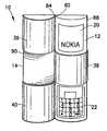
- FIG. 1is a perspective view of a hand-held portable electronic device incorporating features of the invention shown in a first configuration
- FIG. 2is a perspective view of the device shown in FIG. 1 from an opposite direction;
- FIG. 3is a perspective view of the device shown in FIG. 1 in a second configuration
- FIG. 4is a perspective view of the device shown in FIG. 3 from an opposite direction;
- FIG. 5is an exploded perspective view of the device shown in FIGS. 1-4 ;
- FIGS. 6-8are schematic diagrams illustrating the location of the ribbons of the hinge assembly of the device in its configuration shown in FIGS. 1-2 ;
- FIG. 9is a perspective view of the device shown in FIG. 1 ;
- FIG. 10is a perspective view of the device shown in FIG. 9 with the two housing sections rotated 180 degrees relative to each other with the hinge arrangement;
- FIG. 11is a perspective view of the device shown in FIG. 9 with the two housing section rotated 360 degrees relative to each other with the hinge arrangement to an intermediate position;
- FIGS. 12-14are schematic diagrams illustrating the location of the ribbons of the hinge assembly of the device in its configuration shown in FIG. 11 ;
- FIG. 15is a perspective view of the device shown in FIG. 11 with the two housing sections rotated 180 degrees relative to each other from the intermediate position;
- FIGS. 16-18are schematic diagrams illustrating the location of the ribbons of the hinge assembly of the device in its configuration shown in FIGS. 3-4 .
- FIG. 1there is shown a perspective view of a hand-held portable electronic device 10 incorporating features of the invention.
- a hand-held portable electronic device 10incorporating features of the invention.
- the inventionwill be described with reference to the exemplary embodiment shown in the drawings, it should be understood that the invention can be embodied in many alternate forms of embodiments.
- any suitable size, shape or type of elements or materialscould be used.
- the device 10is a reconfigurable device.
- FIGS. 1 and 2show the device 10 in a first configuration.
- FIGS. 3 and 4shown the device 10 in a second different configuration.
- the device 10generally comprises a first housing section 12 , a second housing section 14 and a hinge arrangement 16 .
- the hinge arrangement 16movably connects the first and second housing sections 12 , 14 to each other between the first and second configurations shown in FIGS. 1-2 and FIGS. 3-4 .
- the deviceis a multifunctional device comprising two primary functions or applications; a mobile telephone function and a camera function.
- Each form factor configurationis adapted to enable a user easier or more user friendly user interface for each primary function.
- the first configuration shown in FIGS. 1-2is for friendly user interface with the mobile telephone function
- the second configuration shown in FIGS. 3-4is for friendly user interface with the camera function.
- any suitable multiple functionscould be provided, such as a mobile telephone and a gaming device, or a camera and a gaming device, or a mobile telephone and a music player similar to an IPOD® for example.
- more than two primary functionscould be provided, and more than two configurations (one for each function) could be provided.
- the first housing section 12generally comprises a first housing member 18 , an electronic display 20 , a user input comprising a keypad 22 , a camera 24 and electronic circuitry 26 .
- the electronic circuitry 26is operably coupled to the electronic display 20 , the keypad 22 , and the camera 24 and can comprise conventional mobile telephone and digital camera components including, for example, a transceiver, an antenna, a memory, a controller or processor, etc.
- the first housing section 12has a general semi-column shape. However, in alternate embodiments any suitable shape could be provided including square or rectangular block shapes for example.
- the display 20 , the keypad 22 and the lens of the camera 24are located at a major exterior side 13 of the first housing section 12 ; which is curved in this embodiment.
- the lens of the camera 24is located in a middle section 72 of the first housing section 12 .
- the display 20is located in a top section 74 of the first housing section 12 .
- the keypad 22is located in a bottom section 76 of the first housing section 12 .
- the keypad 22 and input device 23allow a user to input telephone numbers and alphanumeric letters as is known in the mobile telephone art.
- the display 20functions as a conventional mobile telephone display.
- the second housing section 14generally comprises a second housing member 28 , a display 30 , a user input section 32 , electronic circuitry 34 and a battery 36 .
- the second housing section 14has a general semi-column shape. However, in alternate embodiments any suitable shape could be provided including square or rectangular block shaped for example.
- the display 30 and the user input or control 32are located at a major exterior side 15 of the second housing section 14 ; which is curved in this embodiment.
- the user control 32is located in a top section 94 of the second housing section 14 .
- the display 30is located in a bottom section 96 of the second housing section 14 .
- the display 30forms a display for the camera function of the device 10 .
- the user input section 32has user control and menu buttons for the camera function of the device 10 .
- the hinge arrangement 16generally comprises three ribbons 38 , 39 , 40 .
- the hinge arrangementforms a double acting hinge arrangement connecting the second housing section 12 to the first housing section 14 .
- the double acting hinge arrangement 16comprises the ribbons 38 - 40 to mechanically connect the first and second housing sections to each other. More specifically, in this embodiment the hinge arrangement forms a Jacob's Ladder flipping hinge arrangement.
- a Jacob's Ladder flipping hinge arrangementcomprises a first ribbon which has a first end connected to a first member and a second end connected to a second member wherein the first ribbon wraps around an exterior side of the second member, and a second ribbon which has a first end connected to the second member and a second end connected to the first member wherein the second ribbon wraps around an exterior side of the first member.
- Thisforms two spaced hinges at opposite ends of the first and second members.
- a third ribbonis not necessarily needed, but is provided in the embodiments described to provided a hinge with less flexibility or play in the non-hinging-axes of the configuration. More than three ribbons could also be provided.
- FIGS. 6-7illustrate the location of the ribbons 38 - 39 relative to the first and second housing section 12 , 14 in the first position shown in FIGS. 1-2 .
- the first ribbon 38has a first end 42 connected to the first housing section 12 at connection 44 , and an opposite second end 46 connected to the second housing section 14 at connection 48 .
- the first ribbon 38wraps around the exterior facing side of the first housing section 12 at a middle swath 66 . This covers the middle section 72 .
- the first ribbon 38covers the lens to the camera 24 .
- Top and bottom sections 74 , 76 of the first housing section 12are not covered.
- the second ribbon 39has a first end 50 connected to the first housing section 12 at connection 52 , and an opposite second end 54 connected to the second housing section 14 at connection 56 .
- the second ribbon 39wraps around the exterior facing side of the second housing section 14 at a top end swath 68 .
- the second ribbon 39covers the user input 32 for the camera function.
- the third ribbon 40has a first end 58 connected to the first housing section 12 at connection 60 , and an opposite second end 62 connected to the second housing section 14 at connection 64 .
- the third ribbon 40wraps around the exterior facing side of the second housing section 14 at a bottom end swath 70 .
- the third ribboncovers the display 30 for the camera function.
- the top and bottom sections 94 , 96 of the second housing section 14are covered by the ribbons, but the middle section 92 of the second housing section 14 is not covered by the ribbons.
- the ribbons 38 - 40might only cover portions for the components, such as only some of the buttons of the input 32 for example.
- FIGS. 1-2show the device 10 configured for use as a mobile telephone.
- the first and second housing sections 12 , 14are rotated relative to each other by the user as indicated by arrows 86 .
- FIG. 10shows the first and second housing sections 12 , 14 rotated relative to each other 180 degrees from the position shown in FIGS. 1 , 2 and 9 .
- Lateral sides 82 , 84are still located near each other.
- the ribbons 38 - 40because they are alternatingly wrapped on the housing sections 12 , 14 , keep the housing sections 12 , 14 together.
- the ribbons 38 - 40are flexible to allow them to change shape between curving in one direction or curving in an opposite direction. Any suitable material(s) could be used for the ribbons including an elastic material, a plastic material, a shape memory superelastic material, etc. However, in one type of embodiment at least one of the ribbons is an electrical flat flexible cable; or at least partially includes an electrical flat flexible cable. Each ribbon could include both rigid and flexible parts, and/or composite parts made of different materials.
- the first and second housing sections 12 , 14are shown rotated relative to each another 180 degrees from the position shown in FIG. 10 ; 360 degrees relative to the position shown in FIGS. 1-2 and 9 .
- the ribbons 38 - 40are partially wrapped around the major surface 13 and partially wrapped around the major surface 15 .
- the shapesare in alternating general S patterns.
- the deviceis shown with the first and second housing sections 12 , 14 rotated another 180 degrees relative to the intermediate position shown in FIGS. 11-14 .
- the lateral sides 82 , 84are spaced from each other, but the opposite lateral sides 88 , 90 are located next to each other.
- the deviceis shown with the first and second housing sections 12 , 14 rotated another 180 degrees relative to the position shown in FIG. 15 ; 360 degrees relative to the position shown in FIGS. 11-14 .
- the first ribbon 38wraps around the exterior facing side of the second housing section 14 at a middle swath 98 .
- the first ribbon 38covers the middle section 92 of the second housing section 14 , but does not cover the middle section 72 of the first housing section 12 .
- the lens of the camera 24is uncovered.
- the second ribbon 39covers the top section 74 of the first housing section 12 , but does not cover the top section 94 of the second housing section 14 .
- the top ribbon 39wraps around the exterior facing side of the first housing section 12 at a top swath 100 .
- the third ribbon 40covers the bottom section 76 of the first housing section 12 , but does not cover the bottom section 96 of the second housing section 14 .
- the third ribbon 40wraps around the exterior facing side of the first housing section 12 at a bottom swath 102 .
- the telephone keypad 22is covered, but the display 30 for the camera is not covered.
- the device 10is configured to be reoriented 90 degrees as shown in FIGS. 3 and 4 for picture taking; versus phone use orientation as shown in FIG. 9 .
- An electrical connectionis preferably provided between the electronics in the two housing sections 12 , 14 .
- this electrical connectioncomprises at least one of the ribbons 38 - 40 comprising an electrical flat flexible cable. The ends of the cable would be attached to the electronics in the two housing sections.
- the cablecan provide electrical conductors between the two housing sections 12 , 14 as well as a mechanical component of the hinge arrangement 16 .
- separate electrical conductorscould be connected to one or more of the ribbons 38 - 40 to electrically connect the housing sections 12 , 14 to each other.
- One or more of the electrical conductors in the ribbon(s) 38 - 40could also be used as a switch to signal when the device 10 is in the first configuration shown in FIGS. 1-2 and/or the second configuration shown in FIGS. 3 - 4 .
- a configuration signaling conductor on the ribbon 38could be adapted to electrically contact a contact 104 on the exterior of the first housing section 12 to signal when the device 10 is in the phone mode. However, the contact 104 would not be contacted when the device 10 is in the camera mode. This is only one example. Any suitable type of switch to signal the electronic components of the device regarding the configuration of the device could be provided.
- one or more of the ribbonscould form an antenna or shield for the device 10 .
- contact padscould be provided on the ribbon for electrically connecting the device 10 to a docking station, such as a telephone holder in an automobile, or a camera docking station connected to a personal computer.
- the “ribbons”can be used both as electrical flex cables and also as hiding elements for hiding different elements when the device is in different configurations. For example, hiding camera elements versus hiding phone elements.
- the ribbonsmight not provide a hiding function and/or might not provide an electrical conductor function.
- the ribbonsmight just be used to change the color of the product or covering the phone when it is not in use. For example, first sides of the ribbons could be blue and second opposite sides of the ribbons could be red. Thus, the color could change between blue and red depending on its configuration. This is merely a simple example.
- Different patterns which visually interact with patterns on the exterior surfaces 13 , 15could also be provided, or different product use directions could be provided on different sides of the ribbons; camera directions on one side of the ribbons and phone directions on the opposite sides of the ribbons for example.
- one or more of the ribbonscould have an aperture through it. The ribbons do not need to be uniformly solid in size and shape.
- one or more of the ribbonscould provide additional features such as providing a keypad or touchpad feature for example.
- housing sections 12 , 14are flipped relative to each other.
- only a portion of the housing sectionsmight be flipped relative to another housing section or housing section portion with the invention's Jacob's Ladder flipping hinge arrangement.
- the configuration shown in FIGS. 1-2forms a first form factor operational configuration
- the configuration shown in FIGS. 3-4forms a second form factor operational configuration.
- the first form factor operational configurationprovides a configuration for using the telephone application of the device.
- the second form factor operational configurationprovides a configuration for using the camera application of the device.
- the two form factor operational configurationsavoid the confusion noted above in conventional multi-application devices by hiding controls and user interfaces of applications not being used.
- the first and second housing sectionsare adapted to be moved relative to each other to provide the first form factor operational configuration and the second form factor operational configuration, wherein the device is adapted to function as the mobile telephone when the device is in the first form factor operational configuration, and wherein the device is adapted to function as the at least one other non-telephone application when the device is in the second form factor operational configuration.
- the portable hand held devicemight not comprise a telephone form factor operational configuration.
- the first form factor operational configurationcould comprise a camera and the second form factor operational configuration could comprises a gaming device.
- Other variationsshould be apparent to those skilled in the art after reading of the patent application.
Landscapes
- Engineering & Computer Science (AREA)
- Signal Processing (AREA)
- Telephone Set Structure (AREA)
Abstract
Description
Claims (32)
Priority Applications (2)
| Application Number | Priority Date | Filing Date | Title |
|---|---|---|---|
| US11/604,126US7787912B2 (en) | 2006-11-22 | 2006-11-22 | Portable electronic device with double acting hinge arrangement |
| PCT/IB2007/003456WO2008062270A2 (en) | 2006-11-22 | 2007-11-12 | Mobile phone comprising a jacob's ladder hinge arrangement |
Applications Claiming Priority (1)
| Application Number | Priority Date | Filing Date | Title |
|---|---|---|---|
| US11/604,126US7787912B2 (en) | 2006-11-22 | 2006-11-22 | Portable electronic device with double acting hinge arrangement |
Publications (2)
| Publication Number | Publication Date |
|---|---|
| US20080137271A1 US20080137271A1 (en) | 2008-06-12 |
| US7787912B2true US7787912B2 (en) | 2010-08-31 |
Family
ID=39167643
Family Applications (1)
| Application Number | Title | Priority Date | Filing Date |
|---|---|---|---|
| US11/604,126Expired - Fee RelatedUS7787912B2 (en) | 2006-11-22 | 2006-11-22 | Portable electronic device with double acting hinge arrangement |
Country Status (2)
| Country | Link |
|---|---|
| US (1) | US7787912B2 (en) |
| WO (1) | WO2008062270A2 (en) |
Cited By (20)
| Publication number | Priority date | Publication date | Assignee | Title |
|---|---|---|---|---|
| US20100124948A1 (en)* | 2008-11-14 | 2010-05-20 | Motorola, Inc. | Apparatus for charging a portable electronic device having a rotatable housing |
| US8441791B2 (en) | 2010-12-23 | 2013-05-14 | Microsoft Corporation | Double hinge radial cams |
| US8451601B2 (en) | 2011-01-31 | 2013-05-28 | Microsoft Corporation | Double hinge axial cams |
| USD706743S1 (en)* | 2012-11-20 | 2014-06-10 | Logitech Europe S.A. | Speaker housing |
| US8773849B2 (en) | 2011-04-11 | 2014-07-08 | Microsoft Corporation | Extendable connecting link |
| US8780570B2 (en) | 2011-02-14 | 2014-07-15 | Microsoft Corporation | Double hinge torsion bar |
| US20140238876A1 (en)* | 2013-02-26 | 2014-08-28 | Superior Communications, Inc. | Folio case |
| US20150245517A1 (en)* | 2014-02-21 | 2015-08-27 | Teac Corporation | Transportable electronic device |
| USD743960S1 (en)* | 2013-04-30 | 2015-11-24 | Samsung Display Co., Ltd. | Display device |
| US9535465B2 (en) | 2011-02-10 | 2017-01-03 | Microsoft Technology Licensing, Llc | Hinge electrical interconnection guide |
| US9544670B2 (en) | 2012-11-20 | 2017-01-10 | Logitech Europe S.A. | Covered housing |
| US20170336875A1 (en)* | 2016-05-18 | 2017-11-23 | Kevin R. Stoops | Keyboard/keyboard enclosure |
| US9840861B1 (en) | 2016-06-14 | 2017-12-12 | Microsoft Technology Licensing, Llc | Hinged device with snap open lock |
| US10061359B2 (en) | 2016-07-28 | 2018-08-28 | Microsoft Technology Licensing, Llc | Hinged device with living hinge |
| US10301858B2 (en) | 2016-06-14 | 2019-05-28 | Microsoft Technology Licensing, Llc | Hinge mechanism |
| US10501973B2 (en)* | 2016-06-14 | 2019-12-10 | Microsoft Technology Licensing, Llc | Hinge with free-stop function |
| USD911302S1 (en) | 2018-06-29 | 2021-02-23 | Logitech Europe S.A. | Portable speaker |
| US10936087B2 (en)* | 2016-05-18 | 2021-03-02 | Kevin R. Stoops | Keyboard assembly |
| USD948991S1 (en) | 2017-05-18 | 2022-04-19 | Kevin R. Stoops | Bracket |
| USD1057544S1 (en) | 2021-10-01 | 2025-01-14 | Kevin R. Stoops | Bracket |
Families Citing this family (5)
| Publication number | Priority date | Publication date | Assignee | Title |
|---|---|---|---|---|
| US7688574B2 (en) | 2007-01-05 | 2010-03-30 | Apple Inc. | Cold worked metal housing for a portable electronic device |
| US7864524B2 (en)* | 2008-12-24 | 2011-01-04 | Research In Motion Limited | Multiple-fold portable electronic device |
| US20100269069A1 (en)* | 2009-04-17 | 2010-10-21 | Nokia Corporation | Method and apparatus of associating and maintaining state information for applications |
| US9933914B2 (en) | 2009-07-06 | 2018-04-03 | Nokia Technologies Oy | Method and apparatus of associating application state information with content and actions |
| CN108833632B (en)* | 2018-06-27 | 2020-09-25 | 维沃移动通信有限公司 | Terminal |
Citations (42)
| Publication number | Priority date | Publication date | Assignee | Title |
|---|---|---|---|---|
| US1944696A (en) | 1933-10-17 | 1934-01-23 | Reichl Ernst | Folding panel device |
| AT165425B (en) | 1948-09-11 | 1950-02-25 | Cross-band joint for folding boxes and crates | |
| FR1030268A (en) | 1950-12-29 | 1953-06-11 | Mechanical articulation device | |
| US3501800A (en) | 1967-05-24 | 1970-03-24 | Bernard J O Dea | Hinge for folding screens and the like |
| US4163303A (en) | 1977-09-13 | 1979-08-07 | G. D. Hanna Incorporated | Hinge structure |
| US4558911A (en) | 1983-12-21 | 1985-12-17 | California Institute Of Technology | Rolling contact robot joint |
| GB2189290A (en) | 1986-03-20 | 1987-10-21 | Como & Co Limited | Connecting means for panels |
| GB2203190A (en) | 1987-04-03 | 1988-10-12 | Hinges & Joint Friction Ltd | Hinged structure |
| US4969180A (en)* | 1989-05-18 | 1990-11-06 | I.I.N.V. Computing Ltd. | Cordless pen telephone handset |
| USD318275S (en)* | 1989-08-18 | 1991-07-16 | Kamal Benjelloun | Handset telephone |
| USD322609S (en)* | 1989-05-05 | 1991-12-24 | Mitsubishi Electric Sales America, Inc. | Remote controller |
| GB2254881A (en) | 1991-03-14 | 1992-10-21 | Courier Prod Ltd | Swing doors. |
| EP0612904A2 (en) | 1993-02-26 | 1994-08-31 | Michael Thomas Smith | Hinge arrangements, their construction and use |
| DE4311222A1 (en) | 1993-04-05 | 1994-10-06 | Hans Prof Roericht | Containers for holding objects |
| US5410779A (en) | 1990-03-27 | 1995-05-02 | Esman; Igor I. | Hinge |
| USD364641S (en)* | 1995-01-06 | 1995-11-28 | Tiger Electronics, Inc. | Pen recorder housing |
| US5692046A (en)* | 1995-11-07 | 1997-11-25 | Motorola, Inc. | Foldable telephone handset having transformable hinge |
| US5732757A (en) | 1996-05-10 | 1998-03-31 | Jvm Innovation & Design Llc | Slotted panel and strap combination |
| US5754645A (en)* | 1992-01-21 | 1998-05-19 | Motorola, Inc. | Electronic apparatus having keyless control |
| US6048585A (en) | 1996-11-14 | 2000-04-11 | Atotech Deutschland Gmbh | Removal of orthophosphite ions from electroless nickel plating baths |
| US6101402A (en)* | 1997-09-04 | 2000-08-08 | Ericcson Inc. | Radiotelephone with sliding acoustic member |
| US6292562B1 (en)* | 1995-12-04 | 2001-09-18 | Telenostra As | Keypad for telephones and the like |
| JP2001262747A (en) | 2000-03-21 | 2001-09-26 | Mitsubishi Plastics Ind Ltd | Movable connection panel |
| GB2363821A (en) | 2000-06-20 | 2002-01-09 | Inventec Electronics | Mobile phone cover electrical connector and hinge |
| US20020065104A1 (en)* | 1997-09-16 | 2002-05-30 | Jurgen Hess | Method for inputting information to a mobile radiotelephone |
| US6405029B1 (en)* | 1997-06-19 | 2002-06-11 | Byard G. Nilsson | Wireless prepaid telephone system with dispensable instruments |
| US20020154475A1 (en) | 2001-04-02 | 2002-10-24 | Arto Lammintaus | Folding electronic device |
| USD491542S1 (en)* | 2002-08-17 | 2004-06-15 | Haier Group Corporation | Mobile phone |
| US6788551B2 (en)* | 1999-10-20 | 2004-09-07 | Fujitsu Limited | Foldaway electronic device and flexible cable for same |
| US20040212956A1 (en) | 2003-04-23 | 2004-10-28 | Nokia Corporation | Mobile Terminal with synchronizing hinge |
| US20040229645A1 (en)* | 2003-05-14 | 2004-11-18 | Montgomery Robert D. | Cellular phone and writing instrument in combination |
| US6901245B1 (en)* | 1999-08-20 | 2005-05-31 | Koninklijke Philips Electronics N.V. | Elongate personal communications apparatus |
| USD514078S1 (en)* | 2004-09-22 | 2006-01-31 | Tracy Rookard | Miniature cellular telephone |
| AU2006100021A4 (en) | 2006-01-10 | 2006-02-09 | Charlie Liaw | Container openable and closable in different ways |
| US20060089182A1 (en)* | 2004-10-21 | 2006-04-27 | Nokia Corporation | Elastomeric tensioner and mobile stations using same |
| EP1659764A1 (en) | 2004-11-19 | 2006-05-24 | Siemens Aktiengesellschaft | Hingeless foldable information or communication device |
| JP2006166293A (en) | 2004-12-10 | 2006-06-22 | Sharp Corp | Mobile phone with personal computer |
| US20060148541A1 (en) | 2004-12-30 | 2006-07-06 | Sony Ericsson Mobile Communications Ab | Mobile terminal |
| US7076272B2 (en)* | 2003-08-28 | 2006-07-11 | Niigata Seimitsu Co., Ltd. | Pen-shaped cellular phone |
| US7349216B2 (en)* | 1999-05-25 | 2008-03-25 | Silverbrook Research Pty Ltd | Modular electronic device |
| US7509094B2 (en)* | 2005-06-30 | 2009-03-24 | Modu Ltd. | Wireless telecommunication device and uses thereof |
| US7558057B1 (en)* | 2005-06-06 | 2009-07-07 | Alex Naksen | Personal digital device with adjustable interface |
- 2006
- 2006-11-22USUS11/604,126patent/US7787912B2/ennot_activeExpired - Fee Related
- 2007
- 2007-11-12WOPCT/IB2007/003456patent/WO2008062270A2/enactiveApplication Filing
Patent Citations (42)
| Publication number | Priority date | Publication date | Assignee | Title |
|---|---|---|---|---|
| US1944696A (en) | 1933-10-17 | 1934-01-23 | Reichl Ernst | Folding panel device |
| AT165425B (en) | 1948-09-11 | 1950-02-25 | Cross-band joint for folding boxes and crates | |
| FR1030268A (en) | 1950-12-29 | 1953-06-11 | Mechanical articulation device | |
| US3501800A (en) | 1967-05-24 | 1970-03-24 | Bernard J O Dea | Hinge for folding screens and the like |
| US4163303A (en) | 1977-09-13 | 1979-08-07 | G. D. Hanna Incorporated | Hinge structure |
| US4558911A (en) | 1983-12-21 | 1985-12-17 | California Institute Of Technology | Rolling contact robot joint |
| GB2189290A (en) | 1986-03-20 | 1987-10-21 | Como & Co Limited | Connecting means for panels |
| GB2203190A (en) | 1987-04-03 | 1988-10-12 | Hinges & Joint Friction Ltd | Hinged structure |
| USD322609S (en)* | 1989-05-05 | 1991-12-24 | Mitsubishi Electric Sales America, Inc. | Remote controller |
| US4969180A (en)* | 1989-05-18 | 1990-11-06 | I.I.N.V. Computing Ltd. | Cordless pen telephone handset |
| USD318275S (en)* | 1989-08-18 | 1991-07-16 | Kamal Benjelloun | Handset telephone |
| US5410779A (en) | 1990-03-27 | 1995-05-02 | Esman; Igor I. | Hinge |
| GB2254881A (en) | 1991-03-14 | 1992-10-21 | Courier Prod Ltd | Swing doors. |
| US5754645A (en)* | 1992-01-21 | 1998-05-19 | Motorola, Inc. | Electronic apparatus having keyless control |
| EP0612904A2 (en) | 1993-02-26 | 1994-08-31 | Michael Thomas Smith | Hinge arrangements, their construction and use |
| DE4311222A1 (en) | 1993-04-05 | 1994-10-06 | Hans Prof Roericht | Containers for holding objects |
| USD364641S (en)* | 1995-01-06 | 1995-11-28 | Tiger Electronics, Inc. | Pen recorder housing |
| US5692046A (en)* | 1995-11-07 | 1997-11-25 | Motorola, Inc. | Foldable telephone handset having transformable hinge |
| US6292562B1 (en)* | 1995-12-04 | 2001-09-18 | Telenostra As | Keypad for telephones and the like |
| US5732757A (en) | 1996-05-10 | 1998-03-31 | Jvm Innovation & Design Llc | Slotted panel and strap combination |
| US6048585A (en) | 1996-11-14 | 2000-04-11 | Atotech Deutschland Gmbh | Removal of orthophosphite ions from electroless nickel plating baths |
| US6405029B1 (en)* | 1997-06-19 | 2002-06-11 | Byard G. Nilsson | Wireless prepaid telephone system with dispensable instruments |
| US6101402A (en)* | 1997-09-04 | 2000-08-08 | Ericcson Inc. | Radiotelephone with sliding acoustic member |
| US20020065104A1 (en)* | 1997-09-16 | 2002-05-30 | Jurgen Hess | Method for inputting information to a mobile radiotelephone |
| US7349216B2 (en)* | 1999-05-25 | 2008-03-25 | Silverbrook Research Pty Ltd | Modular electronic device |
| US6901245B1 (en)* | 1999-08-20 | 2005-05-31 | Koninklijke Philips Electronics N.V. | Elongate personal communications apparatus |
| US6788551B2 (en)* | 1999-10-20 | 2004-09-07 | Fujitsu Limited | Foldaway electronic device and flexible cable for same |
| JP2001262747A (en) | 2000-03-21 | 2001-09-26 | Mitsubishi Plastics Ind Ltd | Movable connection panel |
| GB2363821A (en) | 2000-06-20 | 2002-01-09 | Inventec Electronics | Mobile phone cover electrical connector and hinge |
| US20020154475A1 (en) | 2001-04-02 | 2002-10-24 | Arto Lammintaus | Folding electronic device |
| USD491542S1 (en)* | 2002-08-17 | 2004-06-15 | Haier Group Corporation | Mobile phone |
| US20040212956A1 (en) | 2003-04-23 | 2004-10-28 | Nokia Corporation | Mobile Terminal with synchronizing hinge |
| US20040229645A1 (en)* | 2003-05-14 | 2004-11-18 | Montgomery Robert D. | Cellular phone and writing instrument in combination |
| US7076272B2 (en)* | 2003-08-28 | 2006-07-11 | Niigata Seimitsu Co., Ltd. | Pen-shaped cellular phone |
| USD514078S1 (en)* | 2004-09-22 | 2006-01-31 | Tracy Rookard | Miniature cellular telephone |
| US20060089182A1 (en)* | 2004-10-21 | 2006-04-27 | Nokia Corporation | Elastomeric tensioner and mobile stations using same |
| EP1659764A1 (en) | 2004-11-19 | 2006-05-24 | Siemens Aktiengesellschaft | Hingeless foldable information or communication device |
| JP2006166293A (en) | 2004-12-10 | 2006-06-22 | Sharp Corp | Mobile phone with personal computer |
| US20060148541A1 (en) | 2004-12-30 | 2006-07-06 | Sony Ericsson Mobile Communications Ab | Mobile terminal |
| US7558057B1 (en)* | 2005-06-06 | 2009-07-07 | Alex Naksen | Personal digital device with adjustable interface |
| US7509094B2 (en)* | 2005-06-30 | 2009-03-24 | Modu Ltd. | Wireless telecommunication device and uses thereof |
| AU2006100021A4 (en) | 2006-01-10 | 2006-02-09 | Charlie Liaw | Container openable and closable in different ways |
Cited By (31)
| Publication number | Priority date | Publication date | Assignee | Title |
|---|---|---|---|---|
| US8126516B2 (en)* | 2008-11-14 | 2012-02-28 | Motorola Mobility, Inc. | Apparatus for charging a portable electronic device having a rotatable housing |
| US20100124948A1 (en)* | 2008-11-14 | 2010-05-20 | Motorola, Inc. | Apparatus for charging a portable electronic device having a rotatable housing |
| US8441791B2 (en) | 2010-12-23 | 2013-05-14 | Microsoft Corporation | Double hinge radial cams |
| US8451601B2 (en) | 2011-01-31 | 2013-05-28 | Microsoft Corporation | Double hinge axial cams |
| US9535465B2 (en) | 2011-02-10 | 2017-01-03 | Microsoft Technology Licensing, Llc | Hinge electrical interconnection guide |
| US8780570B2 (en) | 2011-02-14 | 2014-07-15 | Microsoft Corporation | Double hinge torsion bar |
| US9069531B2 (en) | 2011-02-14 | 2015-06-30 | Microsoft Technology Licensing, Llc | Portable device and mobile phone with double hinge torsion bar |
| US8773849B2 (en) | 2011-04-11 | 2014-07-08 | Microsoft Corporation | Extendable connecting link |
| USD706743S1 (en)* | 2012-11-20 | 2014-06-10 | Logitech Europe S.A. | Speaker housing |
| USD780153S1 (en) | 2012-11-20 | 2017-02-28 | Logitech Europe S.A. | Speaker housing |
| US9544670B2 (en) | 2012-11-20 | 2017-01-10 | Logitech Europe S.A. | Covered housing |
| US20140238876A1 (en)* | 2013-02-26 | 2014-08-28 | Superior Communications, Inc. | Folio case |
| US9086845B2 (en)* | 2013-02-26 | 2015-07-21 | Superior Communications, Inc. | Folio case |
| USD743960S1 (en)* | 2013-04-30 | 2015-11-24 | Samsung Display Co., Ltd. | Display device |
| US20150245517A1 (en)* | 2014-02-21 | 2015-08-27 | Teac Corporation | Transportable electronic device |
| US9706025B2 (en)* | 2014-02-21 | 2017-07-11 | Teac Corporation | Transportable electronic device |
| US10345920B2 (en)* | 2016-05-18 | 2019-07-09 | Kevin R. Stoops | Keyboard/keyboard enclosure |
| US10642374B2 (en)* | 2016-05-18 | 2020-05-05 | Kevin R. Stoops | Keyboard/keyboard enclosure |
| US20240345663A1 (en)* | 2016-05-18 | 2024-10-17 | Kevin R. Stoops | Keyboard assembly |
| US12019810B2 (en) | 2016-05-18 | 2024-06-25 | Kevin R. Stoops | Keyboard assembly |
| US20170336875A1 (en)* | 2016-05-18 | 2017-11-23 | Kevin R. Stoops | Keyboard/keyboard enclosure |
| US10936087B2 (en)* | 2016-05-18 | 2021-03-02 | Kevin R. Stoops | Keyboard assembly |
| US10501973B2 (en)* | 2016-06-14 | 2019-12-10 | Microsoft Technology Licensing, Llc | Hinge with free-stop function |
| US9840861B1 (en) | 2016-06-14 | 2017-12-12 | Microsoft Technology Licensing, Llc | Hinged device with snap open lock |
| US20190264483A1 (en)* | 2016-06-14 | 2019-08-29 | Microsoft Technology Licensing, Llc | Hinge mechanism |
| US11028628B2 (en)* | 2016-06-14 | 2021-06-08 | Microsoft Technology Licensing, Llc | Hinge mechanism |
| US10301858B2 (en) | 2016-06-14 | 2019-05-28 | Microsoft Technology Licensing, Llc | Hinge mechanism |
| US10061359B2 (en) | 2016-07-28 | 2018-08-28 | Microsoft Technology Licensing, Llc | Hinged device with living hinge |
| USD948991S1 (en) | 2017-05-18 | 2022-04-19 | Kevin R. Stoops | Bracket |
| USD911302S1 (en) | 2018-06-29 | 2021-02-23 | Logitech Europe S.A. | Portable speaker |
| USD1057544S1 (en) | 2021-10-01 | 2025-01-14 | Kevin R. Stoops | Bracket |
Also Published As
| Publication number | Publication date |
|---|---|
| US20080137271A1 (en) | 2008-06-12 |
| WO2008062270A3 (en) | 2008-10-30 |
| WO2008062270A2 (en) | 2008-05-29 |
Similar Documents
| Publication | Publication Date | Title |
|---|---|---|
| US7787912B2 (en) | Portable electronic device with double acting hinge arrangement | |
| EP1703709A1 (en) | Portable terminal having replaceable modules | |
| KR100678041B1 (en) | Portable digital communication device with sliding / rotating hinge means | |
| KR100800677B1 (en) | Multi-axis hinge device of mobile terminal and connecting member having same | |
| US8060155B2 (en) | Port cover opening/closing device for portable terminal | |
| US7483723B2 (en) | Flexible conductors connected between two parts of a portable electronic device | |
| EP1353487B1 (en) | Mobile terminal | |
| EP3279762A1 (en) | Handheld device enclosure | |
| EP1843555B1 (en) | Slim portable terminal | |
| EP1703702A1 (en) | Hinged portable radio communication equipment with a double action hinge | |
| EP1422593A1 (en) | Flexible conductors connected between two parts of a portable electronic device | |
| US7447528B2 (en) | Multifunction electronic device | |
| EP1594290B1 (en) | Two-way folder-type terminal | |
| CN1277400C (en) | foldable communication device | |
| EP1119156A1 (en) | Foldable portable communication terminal device | |
| KR20060042169A (en) | Gaming Portable Communication Device | |
| CN100562029C (en) | Rotatable slide type portable terminal | |
| KR100487223B1 (en) | Portable phone with direction-variable microphone | |
| KR100716715B1 (en) | Rotary Bar Type Handheld Wireless Terminal | |
| KR100630357B1 (en) | Cell phone handset | |
| KR100640506B1 (en) | Swing type mobile terminal | |
| CN2713748Y (en) | Collapsible mobile phone | |
| KR100842632B1 (en) | Handheld terminal | |
| KR20010026577A (en) | Variable type of cordless telephone | |
| KR100651496B1 (en) | Flexible circuit of electronic devices |
Legal Events
| Date | Code | Title | Description |
|---|---|---|---|
| AS | Assignment | Owner name:NOKIA CORPORATION, FINLAND Free format text:ASSIGNMENT OF ASSIGNORS INTEREST;ASSIGNOR:SAILA, SAMI;REEL/FRAME:018617/0566 Effective date:20061122 | |
| FEPP | Fee payment procedure | Free format text:PAYOR NUMBER ASSIGNED (ORIGINAL EVENT CODE: ASPN); ENTITY STATUS OF PATENT OWNER: LARGE ENTITY | |
| FPAY | Fee payment | Year of fee payment:4 | |
| AS | Assignment | Owner name:NOKIA TECHNOLOGIES OY, FINLAND Free format text:ASSIGNMENT OF ASSIGNORS INTEREST;ASSIGNOR:NOKIA CORPORATION;REEL/FRAME:035603/0543 Effective date:20150116 | |
| AS | Assignment | Owner name:PROVENANCE ASSET GROUP LLC, CONNECTICUT Free format text:ASSIGNMENT OF ASSIGNORS INTEREST;ASSIGNORS:NOKIA TECHNOLOGIES OY;NOKIA SOLUTIONS AND NETWORKS BV;ALCATEL LUCENT SAS;REEL/FRAME:043877/0001 Effective date:20170912 Owner name:NOKIA USA INC., CALIFORNIA Free format text:SECURITY INTEREST;ASSIGNORS:PROVENANCE ASSET GROUP HOLDINGS, LLC;PROVENANCE ASSET GROUP LLC;REEL/FRAME:043879/0001 Effective date:20170913 Owner name:CORTLAND CAPITAL MARKET SERVICES, LLC, ILLINOIS Free format text:SECURITY INTEREST;ASSIGNORS:PROVENANCE ASSET GROUP HOLDINGS, LLC;PROVENANCE ASSET GROUP, LLC;REEL/FRAME:043967/0001 Effective date:20170913 | |
| FEPP | Fee payment procedure | Free format text:MAINTENANCE FEE REMINDER MAILED (ORIGINAL EVENT CODE: REM.) | |
| LAPS | Lapse for failure to pay maintenance fees | Free format text:PATENT EXPIRED FOR FAILURE TO PAY MAINTENANCE FEES (ORIGINAL EVENT CODE: EXP.); ENTITY STATUS OF PATENT OWNER: LARGE ENTITY | |
| STCH | Information on status: patent discontinuation | Free format text:PATENT EXPIRED DUE TO NONPAYMENT OF MAINTENANCE FEES UNDER 37 CFR 1.362 | |
| FP | Lapsed due to failure to pay maintenance fee | Effective date:20180831 | |
| AS | Assignment | Owner name:NOKIA US HOLDINGS INC., NEW JERSEY Free format text:ASSIGNMENT AND ASSUMPTION AGREEMENT;ASSIGNOR:NOKIA USA INC.;REEL/FRAME:048370/0682 Effective date:20181220 | |
| AS | Assignment | Owner name:PROVENANCE ASSET GROUP LLC, CONNECTICUT Free format text:RELEASE BY SECURED PARTY;ASSIGNOR:CORTLAND CAPITAL MARKETS SERVICES LLC;REEL/FRAME:058983/0104 Effective date:20211101 Owner name:PROVENANCE ASSET GROUP HOLDINGS LLC, CONNECTICUT Free format text:RELEASE BY SECURED PARTY;ASSIGNOR:CORTLAND CAPITAL MARKETS SERVICES LLC;REEL/FRAME:058983/0104 Effective date:20211101 Owner name:PROVENANCE ASSET GROUP LLC, CONNECTICUT Free format text:RELEASE BY SECURED PARTY;ASSIGNOR:NOKIA US HOLDINGS INC.;REEL/FRAME:058363/0723 Effective date:20211129 Owner name:PROVENANCE ASSET GROUP HOLDINGS LLC, CONNECTICUT Free format text:RELEASE BY SECURED PARTY;ASSIGNOR:NOKIA US HOLDINGS INC.;REEL/FRAME:058363/0723 Effective date:20211129 | |
| AS | Assignment | Owner name:RPX CORPORATION, CALIFORNIA Free format text:ASSIGNMENT OF ASSIGNORS INTEREST;ASSIGNOR:PROVENANCE ASSET GROUP LLC;REEL/FRAME:059352/0001 Effective date:20211129 |