US7787823B2 - Radio-over-fiber (RoF) optical fiber cable system with transponder diversity and RoF wireless picocellular system using same - Google Patents
Radio-over-fiber (RoF) optical fiber cable system with transponder diversity and RoF wireless picocellular system using sameDownload PDFInfo
- Publication number
- US7787823B2 US7787823B2US11/521,717US52171706AUS7787823B2US 7787823 B2US7787823 B2US 7787823B2US 52171706 AUS52171706 AUS 52171706AUS 7787823 B2US7787823 B2US 7787823B2
- Authority
- US
- United States
- Prior art keywords
- transponder
- optical fiber
- transponders
- fiber cable
- rof
- Prior art date
- Legal status (The legal status is an assumption and is not a legal conclusion. Google has not performed a legal analysis and makes no representation as to the accuracy of the status listed.)
- Expired - Fee Related, expires
Links
Images


Classifications
- H—ELECTRICITY
- H04—ELECTRIC COMMUNICATION TECHNIQUE
- H04B—TRANSMISSION
- H04B10/00—Transmission systems employing electromagnetic waves other than radio-waves, e.g. infrared, visible or ultraviolet light, or employing corpuscular radiation, e.g. quantum communication
- H04B10/25—Arrangements specific to fibre transmission
- H04B10/2575—Radio-over-fibre, e.g. radio frequency signal modulated onto an optical carrier
- H04B10/25752—Optical arrangements for wireless networks
- H04B10/25758—Optical arrangements for wireless networks between a central unit and a single remote unit by means of an optical fibre
- H04B10/25759—Details of the reception of RF signal or the optical conversion before the optical fibre
- H—ELECTRICITY
- H04—ELECTRIC COMMUNICATION TECHNIQUE
- H04B—TRANSMISSION
- H04B10/00—Transmission systems employing electromagnetic waves other than radio-waves, e.g. infrared, visible or ultraviolet light, or employing corpuscular radiation, e.g. quantum communication
- H04B10/25—Arrangements specific to fibre transmission
- H04B10/2575—Radio-over-fibre, e.g. radio frequency signal modulated onto an optical carrier
- H04B10/25752—Optical arrangements for wireless networks
- H04B10/25753—Distribution optical network, e.g. between a base station and a plurality of remote units
- H04B10/25756—Bus network topology
Definitions
- the present inventionrelates generally to wireless communication systems, and in particular relates to centralized optical-fiber-based wireless systems and methods employing radio-frequency (RF) transmission over optical fiber.
- RFradio-frequency
- Wireless communicationis rapidly growing, with ever-increasing demands for high-speed mobile data communication.
- so-called “wireless fidelity” or “WiFi” systems and wireless local area networks (WLANs)are being deployed in many different types of areas (coffee shops, airports, libraries, etc.).
- Wireless communication systemscommunicate with wireless devices called “clients,” which must reside within the wireless range or “cell coverage area” in order to communicate with the access point device.
- Picocellsare radio-frequency (RF) coverage areas having a radius in the range from about a few meters up to about 20 meters. Because a picocell covers a small area, there are typically only a few users (clients) per picocell. Picocells also allow for selective wireless coverage in small regions that otherwise would have poor signal strength when covered by larger cells created by conventional base stations.
- RFradio-frequency
- picocellsare created by and centered on a wireless access point device connected to a head-end controller.
- the wireless access point deviceincludes digital information processing electronics, a RF transmitter/receiver, and an antenna operably connected to the RF transmitter/receiver.
- the size of a given picocellis determined by the amount of RF power transmitted by the access point device, the receiver sensitivity, antenna gain and the RF environment, as well as by the RF transmitter/receiver sensitivity of the wireless client device.
- Client devicesusually have a fixed RF receiver sensitivity, so that the above-mentioned properties of the access point device mainly determine the picocell size.
- Combining a number of access point devices connected to the head-end controllercreates an array of picocells that cover an area called a “picocellular coverage area.” A closely packed picocellular array provides high per-user data-throughput over the picocellular coverage area.
- Prior art wireless systems and networksare wire-based signal distribution systems where the access point devices are treated as separate processing units linked to a central location. This makes the wireless system/network relatively complex and difficult to scale, particularly when many picocells need to cover a large region. Further, the digital information processing performed at the access point devices requires that these devices be activated and controlled by the head-end controller, which further complicates the distribution and use of numerous access point devices to produce a large picocellular coverage area.
- picocellular wireless systemsinvolves providing a number of different services (e.g., WLAN, voice, RFID tracking, temperature and/or light control) within a building, usually by deploying one or more optical fiber cables close to the ceiling.
- a problem with such cable installationis the chance of one or more transponders being obstructed by a portion of the building structure, such as metallic framework of a drop-down ceiling. The effect of such an obstruction degrades the radiation characteristics of the antenna, which reduces the ability of the picocell to properly function.
- Another problemis the multi-path (fading) nature of signal propagation in indoor wireless environments. This simply means that local maximas and minimas of desired signals can exist over a picocell coverage area A receiver antenna located at a maximum location will have better performance than a receiver antenna located in a minimum position.
- Radio-over-fiber (RoF) optical fiber cable system with transponder diversity for a RoF wireless picocellular systemincludes at least one optical fiber cable and two or more transponders optically supported by the at least one optical fiber cable.
- the two or more transpondersare arranged to form one or more groups of two or more proximately located transponders.
- the transponders in a given transponder groupare adapted to form corresponding two or more substantially co-located picocells.
- the systemalso includes a diversity combiner optically coupled to each transponder.
- the diversity combineris adapted to determine respective signal strengths from each transponder in each transponder group to ensure the transponder with the greatest signal strength in a given transponder group is used to form the picocell for the given group.
- the systemincludes one or more RoF optical fiber cables adapted to operably support, either individually or collectively, one or more transponder groups each having two or more transponders. Each transponder is adapted to form a picocell substantially co-located with picocells formed by the other transponders in the corresponding transponder group.
- the systemalso includes a central head-end station optically coupled to the one or more RoF optical fiber cables. The central head-end station is adapted to provide downlink optical signals to each transponder and receive uplink optical signals from each transponder.
- the systemfurther includes a diversity combiner operably coupled to or included in the central head-end station.
- the diversity combineris adapted to receive uplink signals from each transponder to determine relative uplink signal strengths from each transponder in each transponder group, including a greatest uplink signal strength.
- the central head-end stationthen provides the downlink optical signals to the transponder in each transponder group having the greatest uplink signal strength.
- Another aspect of the inventionis a method of providing transponder diversity in a RoF wireless picocellular system.
- the methodincludes optically supporting in one or more RoF optical fiber cables one or more transponder groups each having two or more transponders, wherein the transponders in each transponder group are arranged to form substantially co-located picocells.
- the methodalso includes determining whether a transponder in a given transponder group has a greater signal strength than the other transponders in the group.
- the methodfurther includes addressing the transponder having the greater signal strength.
- FIG. 1is a schematic diagram of a generalized embodiment of an optical-fiber-based wireless picocellular system according to the present invention showing a head-end unit optically coupled to a transponder via an optical fiber RF communication link, along with the picocell formed by the transponder and a client device within the picocell;
- FIG. 2is a detailed schematic diagram of an example embodiment of the system of FIG. 1 , showing the details of the head-end unit, the optical fiber RF communication link and the transponder;
- FIG. 3is a close-up view of an alternative example embodiment for the transponder of the wireless system of FIG. 2 , wherein the transponder includes a transmitting antenna and a receiving antenna;
- FIG. 4is a schematic diagram of an example embodiment of an optical-fiber-based wireless picocellular system according to the present invention that utilizes a central head-end station and multiple transponders arranged along an optical fiber cable;
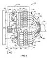
- FIG. 5is a detailed schematic diagram of an example embodiment of the central head-end station of the system of FIG. 4 ;
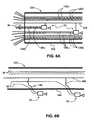
- FIG. 6Ais a close-up cut-away view of the optical fiber cable of the system of FIG. 4 , showing two transponders, the downlink and uplink optical fibers, and the electrical power line that powers the transponders;
- FIG. 6Bis a schematic diagram similar to FIG. 6A , illustrating an example embodiment wherein transponders lie outside of the protective outer jacket of the optical fiber cable.
- FIG. 7is a close-up view of one of the transponders in the optical fiber cable, illustrating the corresponding picocell and the exchange of electromagnetic RF service signals between the transponder and client devices within the picocell;
- FIG. 8is a schematic diagram of an example embodiment of an optical-fiber-based picocellular system that includes a central head-end station and multiple optical fiber cables;
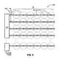
- FIG. 9is a schematic “top-down view” of the system of FIG. 8 , illustrating the extended picocell coverage area created by the multiple optical fiber cables;
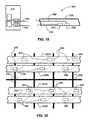
- FIG. 10is a cut-away view of a building infrastructure illustrating an example embodiment wherein the optical-fiber-based wireless picocellular system of the present invention is incorporated into the building infrastructure;
- FIG. 11is a schematic diagram of an example embodiment of a multi-section cable used in the system of FIG. 10 to distribute the transponders throughout the building infrastructure;
- FIG. 12is a schematic plan view of the second floor of the building infrastructure of FIG. 10 , illustrating how three optical fiber cables branch out from the multi-cable connector to create an extended picocellular coverage area for the second floor;
- FIG. 13is a top-down view of an example optical fiber cable system as part of an optical-fiber-based wireless picocellular system, wherein the optical fiber cables are arranged above the suspended ceiling of the building infrastructure shown in FIG. 10 ;
- FIG. 14is a side view of the optical fiber cable system as shown in FIG. 13 , illustrating the formation of the picocells by each transponder to form a picocellular coverage area within the room;
- FIG. 15is similar to FIG. 13 , and illustrates how certain transponders in the optical fiber cable system can be obstructed by portions of the ceiling frame of the suspended ceiling;
- FIG. 16is similar to FIG. 14 , and illustrates how the ceiling frame obstruction shown in FIG. 15 can inhibit the formation of picocells and adversely impact the picocellular coverage area;
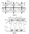
- FIG. 17is a close-up plan view similar to that of FIG. 13 and FIG. 15 , and illustrates an example embodiment of an optical fiber cable system that includes one or more optical fiber cables that each have transponders 30 A and 30 B arranged to provide spatial transponder diversity for the optical fiber cable system;
- FIG. 18is similar to FIG. 14 and FIG. 16 , and shows how a picocell is formed in the leftmost transponder pair by addressing the rightmost transponder of the pair when the leftmost transponder in the pair is obstructed by ceiling frame cross member;
- FIG. 19is a simplified schematic diagram of the wireless picocellular system of FIG. 8 , illustrating a modification to the central head-end station to include a diversity combiner that allows for the central head-end station to switch between diversity transponders associated with a given picocell based on signal strength;
- FIG. 20is a schematic diagram similar to that of FIG. 17 , illustrating another example embodiment of an optical fiber cable system according to the present invention, wherein transponder diversity is achieved using pairs of optical fiber cables;
- FIG. 21is a schematic diagram similar to FIG. 20 , illustrating two different example embodiments of the optical fiber cable system of the present invention that utilizes either a single optical fiber cable or pairs of optical fiber cables to provide polarization diversity;
- FIG. 22is a schematic diagram similar to FIG. 21 , illustrating an example embodiment where either a single optical fiber cable or a pair of optical fiber cables is/are used to provide spatial diversity for the optical fiber cable system using transponders having the same antenna polarization;
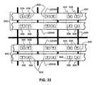
- FIG. 23is a schematic diagram similar to FIG. 22 , illustrating how pairs of optical fibers are used in the optical fiber cable system to provide both polarization diversity and spatial diversity.
- FIG. 1is a schematic diagram of a generalized embodiment of an optical-fiber-based wireless picocellular system 10 according to the present invention.
- System 10includes a head-end unit 20 , one or more transponder units (“transponder”) 30 and an optical fiber RF communication link 36 that optically couples the head-end unit to the transponder.
- system 10has a picocell 40 substantially centered about transponder 30 .
- the one or more transponders 30form a picocellular coverage area 44 .
- Head-end unit 20is adapted to perform or to facilitate any one of a number of RF-over-fiber applications, such as radio-frequency identification (RFID), wireless local-area network (WLAN) communication, or cellular phone service.
- RFIDradio-frequency identification
- WLANwireless local-area network
- Shown within picocell 40is a client device 45 in the form of a computer.
- Client device 45includes an antenna 46 (e.g., a wireless card) adapted to receive and/or send electromagnetic RF signals.
- FIG. 2is a detailed schematic diagram of an example embodiment of system 10 of FIG. 1 .
- head-end unit 20includes a service unit 50 that provides electrical RF service signals for a particular wireless service or application.
- service unit 50provides electrical RF service signals by passing (or conditioning and then passing) such signals from one or more outside networks 223 , as described below. In a particular example embodiment, this includes providing WLAN signal distribution as specified in the IEEE 802.11 standard, i.e., in the frequency range from 2.4 to 2.5 GHz and from 5.0 to 6.0 GHz.
- service unit 50provides electrical RF service signals by generating the signals directly.
- service unit 50coordinates the delivery of the electrical RF service signals between client devices within picocellular coverage area 44 .
- E/O converter 60receives an electrical RF service signal from the service unit and converts it to corresponding optical signal, as discussed in greater detail below.
- E/O converter 60includes a laser suitable for delivering sufficient dynamic range for the RF-over-fiber applications of the present invention, and optionally includes a laser driver/amplifier electrically coupled to the laser.
- suitable lasers for E/O converter 60include laser diodes, distributed feedback (DFB) lasers, Fabry-Perot (FP) lasers, and vertical cavity surface emitting lasers (VCSELs).
- Head-end unit 20also includes an optical-to-electrical (O/E) converter 62 electrically coupled to service unit 50 .
- O/E converter 62receives an optical RF service signal and converts it to a corresponding electrical signal.
- O/E converteris a photodetector, or a photodetector electrically coupled to a linear amplifier.
- E/O converter 60 and O/E converter 62constitute a “converter pair” 66 .
- service unit 50includes a RF signal modulator/demodulator unit 70 for modulating/demodulating RF signals, a digital signal processing unit (“digital signal processor”) 72 , a central processing unit (CPU) 74 for processing data and otherwise performing logic and computing operations, and a memory unit 76 for storing data, such as RFID tag information or data to be transmitted over the WLAN.
- digital signal processordigital signal processing unit
- CPUcentral processing unit
- memory unit 76for storing data, such as RFID tag information or data to be transmitted over the WLAN.
- transponder 30includes a converter pair 66 , wherein the E/O converter 60 and the O/E converter 62 therein are electrically coupled to an antenna system 100 via a RF signal-directing element 106 , such as a circulator.
- Signal-directing element 106serves to direct the downlink and uplink electrical RF service signals, as discussed below.
- antenna system 100includes one or more patch antennas, such as disclosed in U.S. patent application Ser. No. 11/504,999 filed Aug. 16, 2006 and U.S. patent application Ser. No. 11/451,553 filed Jun. 12, 2006, which patent applications are incorporated herein by reference in their entirety.
- FIG. 3is a close-up view of an alternative example embodiment for transponder 30 that includes two antennae: a transmitting antenna 100 T electrically coupled to O/E converter 62 , and a receiving antenna 100 R electrically coupled to O/E converter 60 .
- the two-antenna embodimentobviates the need for RF signal-directing element 106 .
- Transponders 30 of the present inventiondiffer from the typical access point device associated with wireless communication systems in that the preferred embodiment of the transponder has just a few signal-conditioning elements and no digital information processing capability. Rather, the information processing capability is located remotely in head-end unit 20 , and in a particular example, in service unit 50 . This allows transponder 30 to be very compact and virtually maintenance free. In addition, the preferred example embodiment of transponder 30 consumes very little power, is transparent to RF signals, and does not require a local power source, as described below.
- an example embodiment of optical fiber RF communication link 36includes a downlink optical fiber 136 D having an input end 138 and an output end 140 , and an uplink optical fiber 136 U having an input end 142 and an output end 144 .
- the downlink and uplink optical fibers 136 D and 136 Uoptically couple converter pair 66 at head-end unit 20 to the converter pair at transponder 30 .
- downlink optical fiber input end 138is optically coupled to E/O converter 60 of head-end unit 20
- output end 140is optically coupled to O/E converter 62 at transponder 30 .
- uplink optical fiber input end 142is optically coupled to E/O converter 60 of transponder 30
- output end 144is optically coupled to O/E converter 62 at head-end unit 20 .
- the optical-fiber-based wireless picocellular system 10 of the present inventionemploys a known telecommunications wavelength, such as 850 nm, 1300 nm, or 1550 nm. In another example embodiment, system 10 employs other less common but suitable wavelengths such as 980 nm.
- Example embodiments of system 10include either single-mode optical fiber or multimode optical fiber for downlink and uplink optical fibers 136 D and 136 U.
- the particular type of optical fiberdepends on the application of system 10 . For many in-building deployment applications, maximum transmission distances typically do not exceed 300 meters. The maximum length for the intended RF-over-fiber transmission needs to be taken into account when considering using multi-mode optical fibers for downlink and uplink optical fibers 136 D and 136 U. For example, it has been shown that a 1400 MHz.km multi-mode fiber bandwidth-distance product is sufficient for 5.2 GHz transmission up to 300 m.
- the present inventionemploys 50 ⁇ m multi-mode optical fiber for the downlink and uplink optical fibers 136 D and 136 U, and E/O converters 60 that operate at 850 nm using commercially available VCSELs specified for 10 Gb/s data transmission.
- OM3 50 ⁇ m multi-mode optical fiberis used for the downlink and uplink optical fibers 136 D and 136 U.
- Wireless system 10also includes a power supply 160 that generates an electrical power signal 162 .
- Power supply 160is electrically coupled to head-end unit 20 for powering the power-consuming elements therein.
- an electrical power line 168runs through the head-end unit and over to transponder 30 to power E/O converter 60 and O/E converter 62 in converter pair 66 , the optional RF signal-directing element 106 (unless element 106 is a passive device such as a circulator), and any other power-consuming elements (not shown).
- electrical power line 168includes two wires 170 and 172 that carry a single voltage and that are electrically coupled to a DC power converter 180 at transponder 30 .
- DC power converter 180is electrically coupled to E/O converter 60 and O/E converter 62 , and changes the voltage or levels of electrical power signal 162 to the power level(s) required by the power-consuming components in transponder 30 .
- DC power converter 180is either a DC/DC power converter, or an AC/DC power converter, depending on the type of power signal 162 carried by electrical power line 168 .
- electrical power line 168includes standard electrical-power-carrying electrical wire(s), e.g., 18-26 AWG (American Wire Gauge) used in standard telecommunications and other applications.
- electrical power line 168(dashed line) runs directly from power supply 160 to transponder 30 rather than from or through head-end unit 20 .
- electrical power line 168includes more than two wires and carries multiple voltages.
- head-end unit 20is operably coupled to an outside network 223 via a network link 224 .
- service unit 50With reference to the optical-fiber-based wireless picocellular system 10 of FIG. 1 and FIG. 2 , service unit 50 generates an electrical downlink RF service signal SD (“electrical signal SD”) corresponding to its particular application. In an example embodiment, this is accomplished by digital signal processor 72 providing the RF signal modulator 70 with an electrical signal (not shown) that is modulated onto a RF carrier to generate a desired electrical signal SD.
- electrical signal SDelectrical downlink RF service signal SD
- Electrical signal SDis received by E/O converter 60 , which converts this electrical signal into a corresponding optical downlink RF signal SD′ (“optical signal SD′”), which is then coupled into downlink optical fiber 136 D at input end 138 .
- optical signal SD′is tailored to have a given modulation index.
- the modulation power of E/O converter 60is controlled (e.g., by one or more gain-control amplifiers, not shown) to vary the transmission power from antenna system 100 .
- the amount of power provided to antenna system 100is varied to define the size of the associated picocell 40 , which in example embodiments range anywhere from about a meter across to about twenty meters across.
- Optical signal SD′travels over downlink optical fiber 136 to output end 140 , where it is received by O/E converter 62 in transponder 30 .
- O/E converter 62converts optical signal SD′ back into electrical signal SD, which then travels to signal-directing element 106 .
- Signal-directing element 106then directs electrical signal SD to antenna 100 .
- Electrical signal SDis fed to antenna system 100 , causing it to radiate a corresponding electromagnetic downlink RF signal SD′′ (“electromagnetic signal SD′′”).
- electromagnetic signal SD′′is received by client device antenna 46 , which may be part of a wireless card, or a cell phone antenna, for example.
- Antenna 46converts electromagnetic signal SD′′ into electrical signal SD in the client device (signal SD is not shown therein).
- Client device 45then processes electrical signal SD, e.g., stores the signal information in memory, displays the information as an e-mail or text message, etc.
- client device 45generates an electrical uplink RF signal SU (not shown in the client device), which is converted into an electromagnetic uplink RF signal SU′′ (electromagnetic signal SU′′”) by antenna 46 .
- electromagnetic signal SU′′is detected by transponder antenna system 100 , which converts this signal back into electrical signal SU.
- Electrical signal SUis directed by signal-directing element 106 to E/O converter 60 , which converts this electrical signal into a corresponding optical uplink RF signal SU′ (“optical signal SU′”), which is then coupled into input end 142 of uplink optical fiber 136 U.
- Optical signal SU′travels over uplink optical fiber 136 U to output end 144 , where it is received by O/E converter 62 at head-end unit 20 .
- O/E converter 62converts optical signal SU′ back into electrical signal SU, which is then directed to service unit 50 .
- Service unit 50receives and processes signal SU, which in an example embodiment includes one or more of the following: storing the signal information; digitally processing or conditioning the signals; sending the signals on to one or more outside networks 223 via network links 224 ; and sending the signals to one or more client devices 45 in picocellular coverage area 44 .
- the processing of signal SUincludes demodulating this electrical signal in RF signal modulator/demodulator unit 70 , and then processing the demodulated signal in digital signal processor 72 .
- FIG. 4is a schematic diagram of an example embodiment of an optical-fiber-based wireless picocellular system 200 that includes a central head-end station 210 .
- Central head-end station 210can be thought of as a modified head-end unit 20 adapted to handle multiple service units 50 and multiple transponders 30 .
- Central head-end station 210is optically coupled to an optical fiber cable 220 that includes multiple transponders 30 .
- Optical fiber cable 220is constituted by multiple optical fiber RF communication links 36 , with each link optically coupled to a corresponding transponder 30 .
- multiple transponders 30are spaced apart along the length of optical fiber cable 220 (e.g., at 8 meter intervals) to create a desired picocell coverage area 44 made up of picocells 40 , which in practice overlap at the edges.
- FIG. 5is a detailed schematic diagram of an example embodiment of central head-end control station 210 .
- the head-end unitsare modified to allow for each service unit 50 to communicate with one, some, or all of transponders 30 , depending on the particular application of a given service unit.
- Service units 50are each electrically coupled to a RF transmission line 230 and a RF receiving line 232 .
- FIG. 5three of six service units 50 A through 5 OF are shown for the sake of illustration.
- system 200further includes a main controller 250 operably coupled to service units 50 and adapted to control and coordinate the operation of the service units in communicating with transponders 30 .
- controller 250includes a central processing unit (CPU) 252 and a memory unit 254 for storing data.
- CPU 252is adapted (e.g., is programmed) to process information provided to controller 250 by one or more of service units 50 .
- controller 250is or includes a programmable computer adapted to carry out instructions (programs) provided to it or otherwise encoded therein on a computer-readable medium.
- Central head-end station 210further includes a downlink RF signal multiplexer (“downlink multiplexer”) 270 operably coupled to controller 250 .
- Downlink multiplexer unit 270has an input side 272 and an output side 274 .
- Transmission lines 230are electrically connected to downlink multiplexer 270 at input side 272 .
- downlink multiplexer 270includes a RF signal-directing element 280 (e.g., a RF switch) that allows for selective communication between service units 50 and transponders 30 , as described below.
- the selective communicationinvolves sequentially addressing transponders 30 for polling corresponding picocells 40 . Such sequential polling can be used, for example, when one of service units 50 is a RFID reader searching for RFID tags 290 in picocells 40 ( FIG. 4 ).
- RFID tags 290are attached to an item 292 to be tracked or otherwise monitored via the attached RFID tag.
- the selective communicationinvolves simultaneously addressing some or all of transponders 30 . Such simultaneous addressing can be used, for example, when one of service units 50 is a cellular phone transmitter or a RF-signal feed-through unit that provides simultaneous coverage of some or all of picocells 40 .
- Central head-end station 210also includes an uplink RF signal multiplexer (“uplink multiplexer”) 320 operably coupled to controller 250 and having an input side 322 and an output side 324 .
- Receiving lines 232are electrically connected to uplink multiplexer 320 at output side 324 .
- uplink multiplexer 320includes a RF signal-directing element 328 .
- Central head-end station 210also includes a number of E/O converters 60 that make up an E/O converter array 360 , and a corresponding number of O/E converters 62 that make up an O/E converter array 362 .
- E/O converters 60are electrically coupled to output side 274 of downlink multiplexer 270 via electrical lines 330 , and are optically coupled to input ends 138 of corresponding downlink optical fibers 136 D.
- O/E converters 62are electrically coupled to input side 322 of uplink multiplexer 320 via electrical lines 332 , and are optically coupled to output ends 144 of corresponding uplink optical fiber 136 U.
- Downlink optical fibers 136 Dconstitute a downlink optical fiber cable 378 and uplink optical fibers 136 U constitute an uplink optical fiber cable 380 .
- FIG. 6Ais a close-up schematic diagram of optical fiber cable 220 showing downlink and uplink optical fibers 136 D and 136 U and two of the six transponders 30 . Also shown is electrical power line 168 electrically coupled to transponders 30 .
- optical fiber cable 220includes a protective outer jacket 344 .
- transponders 30reside completely within out jacket 344 .
- FIG. 6Bis a schematic diagram similar to FIG. 6A , illustrating an example embodiment wherein transponders 30 lie outside of protective outer jacket 344 . Having transponders 30 lie outside of protective outer jacket 344 makes it easier to arrange the transponders relative to a building infrastructure after the optical fiber cable is deployed, as described below.
- optical-fiber-based wireless picocellular system 200operates as follows.
- service units 50 A, 50 B, . . . 5 OFeach generate or pass through from one or more outside networks 223 respective electrical signals SD that correspond to the particular application of the given service unit.
- Electrical signals SDare transmitted over RF transmission lines 230 to downlink multiplexer 270 .
- Downlink multiplexer 270then combines (in frequency) and distributes the various signals SD to E/O converters 60 in E/O converter array 360 .
- downlink multiplexer 270 and RF signal-directing element 280 thereinare controlled by controller 250 via a control signal S 1 to direct signals SD to one, some or all of E/O converters 60 in E/O converter array 360 and thus to one, some or all of transponders 30 , based on the particular service unit application.
- service unit 50 Ais a cellular phone unit
- signals SD therefrome.g., passing therethrough from one or more outside networks 223
- RF signal-directing element 280are divided (and optionally amplified) equally by RF signal-directing element 280 and provided to each E/O converter 60 in E/O converter array 360 . This results in each transponder 30 being addressed.
- RF signal-directing element 280may be adapted (e.g., programmed) to direct signals SD to select ones of E/O converters 60 in E/O converter array 360 so that only select transponders 30 are addressed.
- E/O converters 60 in E/O converter array 360receive electrical signals SD from downlink multiplexer 270 .
- the addressed E/O converters 60 in E/O converter array 360convert electrical signals SD into corresponding optical signals SD′, which are transmitted over the corresponding downlink optical fibers 136 D to the corresponding transponders 30 .
- the addressed transponders 30convert optical signals SD′ back into electrical signals SD, which are then converted into electromagnetic signals SD′′ that correspond to the particular service unit application.
- FIG. 7is a close-up view of one of transponders 30 in optical fiber cable 220 , illustrating the corresponding picocell 40 and the exchange of downlink and uplink electromagnetic signals SD′′ and SU′′ between the transponder and client devices 45 within the picocell.
- electromagnetic signals SU′′are received by the corresponding transponder 30 and converted to electrical signals SU, and then to optical signals SD′.
- Optical signals SD′then travel over uplink optical fiber 136 U and are received by O/E converter array 362 and the corresponding O/E converters 62 therein for the addressed transponders 30 .
- the O/E converters 60convert optical signals SU′ back to electrical signals SU, which then proceed to uplink multiplexer 320 .
- Uplink multiplexer 320then distributes electrical signals SU to the service unit(s) 50 that require(s) receiving these electrical signals.
- the receiving service units 50process signals SU, which in an example embodiment includes one or more of: storing the signal information; digitally processing or conditioning the signals; sending the signals on to one or more outside networks 223 via network links 224 ; and sending the signals to one or more client devices 45 in picocellular coverage area 44 .
- uplink multiplexer 320 and RF signal-directing element 328 thereinare controlled by controller 250 via a control signal S 2 to direct electrical signals SU to the service unit(s) 50 that require(s) receiving electrical signals SU.
- the different services from some or all of service units 50are combined at the RF signal level by frequency multiplexing.
- a single electrical power line 168 from power supply 160 at central control station 210is incorporated into optical fiber cable 220 and is adapted to power each transponder 30 , as shown in FIG. 6 .
- Each transponder 30taps off the needed amount of power, e.g., via DC converter 180 ( FIG. 2 ). Since the preferred embodiment of transponder 30 has relatively low functionality and power consumption, only relatively low electrical power levels are required (e.g., ⁇ 1 watt), allowing high-gauge wires to be used (e.g., 20 AWG or higher) for electrical power line 168 .
- transponder 30In an example embodiment that uses many transponders 30 (e.g., more than 12) in optical fiber cable 220 , or if the power consumption for transponders 30 is significantly larger than 1 watt due to their particular design, lower-gauge wires or multiple wires are employed in electrical power line 168 .
- the inevitable voltage drop along electrical power line 168 within cable 220typically requires large-range ( ⁇ 30 volts) voltage regulation at each transponder 30 .
- DC power converters 180 at each transponder 30perform this voltage regulation function. If the expected voltage drop is known, then in an example embodiment controller 250 carries out the voltage regulation.
- remote voltage sensing at each transponder 30is used, but this approach is not the preferred one because it adds complexity to the system.
- FIG. 8is a schematic diagram of an example embodiment of a centralized optical-fiber-based wireless picocellular system 400 according the present invention.
- System 400is similar to system 200 as described above, but includes multiple optical fiber cables 220 optically coupled to central head-end station 210 .
- Central head-end station 210includes a number of E/O converter arrays 360 and a corresponding number of O/E converter arrays 362 , arranged in pairs in converter array units 410 , with one converter array unit optically coupled to one optical fiber cable 220 .
- system 400includes a number of downlink multiplexers 270 and uplink multiplexers 320 , arranged in pairs in multiplexer units 414 , with one multiplexer unit electrically coupled to one converter array unit 410 .
- controller 250is electrically coupled to each multiplexer unit 414 and is adapted to control the operation of the downlink and uplink multiplexers 270 and 320 therein.
- arrayis not intended to be limited to components integrated onto a single chip as is often done in the art, but includes an arrangement of discrete, non-integrated components.
- Each E/O converter array 360is electrically coupled to the downlink multiplexer 270 in the corresponding multiplexer unit 414 .
- each O/E converter array 362is electrically coupled to the uplink multiplexer 320 in the corresponding multiplexer unit 414 .
- Service units 50are each electrically coupled to both downlink and uplink multiplexers 270 and 320 within each multiplexer unit 414 .
- Respective downlink and uplink optical fiber cables 378 and 380optically couple each converter array unit 410 to a corresponding optical fiber cable 220 .
- central head-end station 210includes connector ports 420 and optical cables 220 include connectors 422 adapted to connect to the connector ports.
- connectors 422are MT (“Mechanical Transfer”) connectors, such as the UNICAM® MTP connector available from Corning Cable Systems, Inc., Hickory, N.C. In an example embodiment, connectors 422 are adapted to accommodate electrical power line 168 connected to port 420 .
- MTMechanism Transfer
- FIG. 9is a “top down” view of system 400 , showing an extended picocellular coverage area 44 formed by using multiple optical fiber cables 220 .
- system 400supports anywhere from two transponders 30 , to hundreds of transponders, to even thousands of transponders.
- the particular number of transponders employedis not fundamentally limited by the design of system 400 , but rather by the particular application.
- System 400operates in a manner similar to system 200 as described above, except that instead of transponders 30 being in a single optical fiber cable 220 they are distributed over two or more optical fiber cables through the use of corresponding two or more converter array units 410 .
- Electrical signals SD from service units 50are distributed to each multiplexer unit 414 .
- the downlink multiplexers 270 thereinconvey electrical signals SD to one, some, or all of the converter array units 410 , depending on which transponders are to be addresses by which service unit. Electrical signals SD are then processed as described above, with downlink optical signals SD′ being sent to one, some or all of transponders 30 .
- Uplink optical signals SU′ generated by client devices in the corresponding picocells 40return to the corresponding converter units 410 at central head-end station 210 .
- the optical signals SU′are converted to electrical signals SU at the receiving converter unit(s) 410 and are then sent to the uplink multiplexers 320 in the corresponding multiplexer unit(s) 414 .
- Uplink multiplexers 320 thereinare adapted (e.g., programmed by controller 250 ) to direct electrical signals SU to the service unit(s) 50 that require(s) receiving electrical signals SU.
- the receiving service units 50process signals SU, which as discussed above in an example embodiment includes one or more of: storing the signal information; digitally processing or conditioning the signals; sending the signals on to one or more outside networks 223 via network links 224 ; and sending the signals to one or more client devices 45 in picocellular coverage area 44 .
- FIG. 10is a schematic cut-away diagram of a building infrastructure 500 that generally represents any type of building in which the optical-fiber-based wireless picocellular system of the present invention would be useful, such as office buildings, schools, hospitals, college buildings, airports, warehouses, etc.
- Building infrastructure 500includes a first (ground) floor 501 , a second floor 502 , and a third floor 503 .
- First floor 501is defined by a floor 510 and a ceiling 512
- second floor 502is defined by a floor 520 and a ceiling 522
- third floor 503is defined by a floor 530 and a ceiling 532 .
- An example centralized optical-fiber-based wireless picocellular system 400is incorporated into building infrastructure 500 to provide a picocellular coverage area 44 that covers floors 501 , 502 and 503 .
- system 400includes a main cable 540 having a number of different sections that facilitate the placement of a large number of transponders 30 in building infrastructure 500 .
- FIG. 11is a schematic diagram of an example embodiment of main cable 540 .
- Cable 540includes a riser section 542 that carries all of the uplink and downlink optical fiber cables 378 and 380 ( FIG. 8 ) from central head-end station 210 .
- Cabling 540includes one or more multi-cable (MC) connectors 550 adapted to connect select downlink and uplink optical fiber cables 378 and 380 , along with electrical power line 168 , to a number of optical fiber cables 220 .
- MCmulti-cable
- MC connectors 550include individual optical fiber cable ports 420 and optical fiber cables 220 include matching connectors 422 .
- riser section 542includes a total of seventy-two downlink and seventy-two uplink optical fibers 136 D and 136 U, while twelve optical fiber cables 220 each carry six downlink and six uplink optical fibers.
- Main cable 540enables multiple optical fiber cables 220 to be distributed throughout building infrastructure 500 (e.g., fixed to ceilings 512 , 522 and 532 ) to provide an extended picocellular coverage area 44 for the first, second and third floors 501 , 502 and 503 .
- An example type of MC connector 550is a “patch panel” used to connect incoming and outgoing optical fiber cables in an optical telecommunication system.
- electrical power line 168 from power supply 160runs from central head-end station 210 through riser section 542 and branches out into optical fiber cables 220 at MC connectors 550 .
- electrical poweris separately supplied at each MC connector 550 , as indicated by the dashed-box power supplies 160 and dashed-line electrical power lines 168 .
- central head-end station 210 and power supply 160is located within building infrastructure 500 (e.g., in a closet or control room), while in another example embodiment it is located outside of the building at a remote location.
- FIG. 12is a schematic “top down” view of the second floor 502 of building infrastructure 500 , showing three optical fiber cables 220 branching out from MC connector 550 and extending over ceiling 522 .
- Picocells 40 associated with transponders 30(not shown in FIG. 12 ) form an extended picocellular coverage area 44 that covers second floor 502 with fewer, larger picocells than the first and third floors 501 and 503 ( FIG. 10 ).
- Such different picocellular coverage areas 44may be desirable when the different floors have different wireless needs.
- third floor 503might require relatively dense picocell coverage if it serves as storage for items that need to be inventoried and tracked via RFID tags 290 ( FIG. 4 ), which in the present invention can be considered simple client devices 45 .
- second floor 502may be office space that calls for larger and fewer picocells to provide cellular phone service and WLAN coverage.
- FIG. 13is a top-down view of an example optical fiber cable system that includes a number of optical fiber cables 220 as part of an optical-fiber-based wireless picocellular system such as system 400 , wherein the optical fiber cables are arranged between floor 520 and ceiling 522 ( FIG. 10 ) to provide picocellular coverage in room 502 .
- ceiling 522is a drop ceiling having a frame 602 with conducting (e.g., metal) cross members 606 that support ceiling tiles 608 .
- FIG. 14is a side view of the optical fiber cable system as shown in FIG. 13 , illustrating the formation of picocells 40 in room 502 by each transponder 30 to form a picocellular coverage area 44 within the room.
- FIGS. 13 and 14illustrate an idealized situation wherein all transponders 30 are unobstructed so that all of the corresponding picocells 40 are all properly formed.
- FIGS. 15 and 16are similar diagrams to FIGS. 13 and 14 , respectively, and illustrate the case where some of the transponders 30 are obstructed by cross members 606 of ceiling frame 602 .
- Other similar types of obstructionscan also occur, such as from electrical cabling, electrical outlets, and other conducting structures (not shown) that are usually found above a suspended ceiling. When such an obstruction occurs, it can adversely affect the radiation pattern from the transponder antenna system 100 , which in turn can adversely affect the formation of picocell 40 .
- the degradationcan be severe enough to render obstructed transponder(s) 30 ineffective in communicating with client devices 45 that would otherwise fall within a properly formed picocell 40 .
- An aspect of the present inventionuses transponder diversity to mitigate the above-described performance degradation issues in optical-fiber-based wireless picocellular systems that can arise during and after deployment of the one or more RoF optical fiber cables.
- transponder diversityuses transponder diversity to mitigate the above-described performance degradation issues in optical-fiber-based wireless picocellular systems that can arise during and after deployment of the one or more RoF optical fiber cables.
- transponder 30As transponder 30 A or 30 B and an optical fiber cable 220 as optical fiber cable 220 A or 220 B to reflect how the transponders are grouped.
- an optical fiber cable 220 that includes transponders 30 Ais referenced as 220 A
- an optical fiber cable that includes transponders 30 Bis referenced as 220 B
- An optical fiber cable that includes both transponders 30 A and 30 Bis referenced as 220 AB.
- Transponders 30 A and 30 Bmay have the same or different properties (e.g., antenna polarization), depending on the particular example embodiment.
- FIG. 17is a close-up plan view similar to FIG. 13 and FIG. 15 , and illustrates an example embodiment of an optical fiber cable system that includes one or more optical fiber cables 220 AB each having transponders 30 A and 30 B.
- Transponder diversityis achieved in each optical fiber cable 220 AB by spatially arranging two transponders 30 A and 30 B along the length of each optical fiber cable.
- Transponders 30 A and 30 Bare arranged close enough to one another to form a transponder group 600 , which in the present example embodiment can be called a “transponder pair.”
- Transponders 30 A and 30 Brespectively form substantially co-located picocells 40 A and 40 B when addressed.
- transponder 30 Aserves as the main transponder and transponder 30 B serves as a backup transponder and thus remains unaddressed. If transponder 30 A fails to create an acceptable picocell 40 A, then central head-end station 210 ( FIG. 8 ) addresses backup transponder 30 B to form picocell 40 B. In another example embodiment, the transponder that provides the strongest link with client device(s) 45 ( FIG. 7 ) is used.
- FIG. 18is similar to FIG. 14 and FIG. 16 and shows how picocell 40 B is formed in the leftmost transponder pair 600 by addressing transponder 30 B when transponder 30 A is obstructed by ceiling frame cross member 606 .
- FIG. 19is a simplified schematic diagram of wireless picocellular system 400 of FIG. 8 , illustrating a modification to central head-end station 210 to include a diversity combiner 620 electrically coupled to converter array units 410 .
- Transponders 30 A and 30 Bare optically coupled to respective converter array units 410 at central head-end station 210 via respective optical fiber communication links 36 A and 36 B ( FIG. 1 ).
- diversity combiner 620 at central head-end station 210compares the signal strengths from each transponder 30 A and 30 B in each transponder group 600 .
- Central head-end station 210then addresses, for each transponder group 600 , the transponder in the group that has the greatest signal strength. This is accomplished by central head-end station 210 selecting the appropriate downlink optical path (e.g., downlink optical fiber 136 D in optical fiber communication link 36 A or 36 B) for the given “optimum” transponder in the given transponder group 600 .
- the appropriate downlink optical pathe.g., downlink optical fiber
- FIG. 20is a schematic diagram similar to that of FIG. 17 , illustrating another example embodiment of an optical fiber cable system according to the present invention, wherein transponder diversity is achieved using pairs of optical fiber cables 220 A and 220 B.
- two optical fiber cables 220 A and 220 Bare employed that respectively operably support transponders 30 A and 30 B that make up each pair 600 .
- Optical fiber cables 220 A and 220 Bare arranged in close proximity so that transponder pairs 600 of transponders 30 A and 30 B can form corresponding substantially co-located picocells 40 A and 40 B while providing spatial transponder diversity in a manner similar to the embodiment of FIG. 17 .
- the two-optical-fiber-cable arrangementis expanded to include more than two optical fiber cables 220 A and 220 B.
- the main limit on the number of optical fiber cables that can be usedis the ability to keep the transponders that constitute transponder group 600 sufficiently close to one another so that the picocells formed by each transponder are substantially co-located.
- FIG. 21is a schematic diagram similar to FIG. 20 , illustrating two different example embodiments of the optical fiber cable system of the present invention that utilizes either a single optical fiber cable 220 AB or pairs of optical fiber cables 220 A and 220 B to provide polarization diversity.
- a pair 650 of proximately located optical fiber cables 220 A and 220 Bare employed, wherein transponders 30 A in optical fiber cable 220 A have one antenna polarization, e.g., horizontal, as indicated by the arrows within the transponder, while transponders 30 B in optical fiber cable 220 B have an orthogonal antenna polarization, e.g., vertical.
- Optical fiber cables 220 A and 220 Bare arranged to form transponder groups 600 in the form of pairs of transponders 30 A and 30 B.
- antenna system 100FIG. 3 and FIG. 4
- each transponder 30 A and 30 Bincludes an integrated planar antenna system 100 (not shown) to obtain the different polarizations.
- Diversity combiner 620 at central head-end station 210determines the best (e.g., strongest) signal from the orthogonally polarized receiving antennas on the transponders so that the central head-end station addresses the strongest transponder.
- a single optical fiber cable 220 AB that includes proximately located transponders 30 A and 30 B having different polarizationsis used to form transponder pairs 600 .
- FIG. 22is a schematic diagram similar to FIG. 21 , illustrating an example embodiment of the optical fiber cable system of the present invention, where pair 650 of optical fiber cables 220 A and 220 B have transponders 30 A and 30 B with the same antenna polarization (shown as horizontal polarization), but wherein the transponders are arranged in transponder pairs 600 to provide spatial diversity.
- a related example embodimentis also shown in FIG. 22 , wherein a single optical fiber cable 220 AB includes transponder pairs 600 made up of transponders 30 A and 30 B of the same antenna polarization.
- the arrangement of transponders 30 A and 30 B in optical fiber 220 ABachieves the same diversity effect as the pair 650 of optical fiber cables 210 A and 210 B.
- the transponder center-to-center spacing TS for transponders in each transponder group 600is in the range from about 1 wavelength ( ⁇ ) to about 9 ⁇ of the frequency f used.
- the frequency fis either in the 2.4 GHz band or in the 5.2 GHz band.
- two frequencies f 1 and f 2are used.
- FIG. 23is similar to FIG. 22 , and illustrates an example embodiment wherein one or more pairs 650 of optical fiber cables 220 AB is employed.
- Each optical fiber 220 ABincludes both transponders 30 A and 30 B having orthogonal antenna polarizations.
- the transpondersare arranged in pairs in the order 32 A- 32 B, while the other optical fiber cable the transponder pairs are arranged in the order 32 B- 32 A.
- each optical fiber cable pair 650provides a transponder group 600 having four transponders, wherein the transponder group provides both polarization and spatial transponder diversity.
- Diversity combiner 620 at central head-end station 210compares the performance of each transponder in each group 600 so that the central head-end station can address the transponder having the greatest signal strength.
- transponder groups 600 of FIG. 22are used in combination with diversity antennas on client devices 45 ( FIG. 7 ) to provide a Multiple-Input/Multiple-Output (MIMO) configuration to maximize the performance of system 400 .
- MIMOMultiple-Input/Multiple-Output
- Such an arrangementcan be used to achieve an increased bit rate at the same antenna power level.
- the systems of the present inventionare transparent to the types of RF services provided by service units 50 .
- the systemsprovide a supported frequency band or multiple bands. Any service that can operate within the frequency band and within the designed power and dynamic range can be provided. Multiple services can be supported in either the same band or different bands.
- An example embodiment of the systems of the present inventionsupport the IMS and UNII bands, but subsets of these bands or additional frequency bands are also employable.
- licensed bandsare supported to implement cellular signal distribution.
- one or more servicesare added (e.g., via adding new service units 50 ) to the system after the first service is set up and running.
- DASDistributed Antenna System
- the systems of the present inventioncan serve as a distributed antenna system (DAS) that transmits the same signal in some or all of the picocells. This is accomplished by RF signal splitting (and amplification) at the downlink and uplink multiplexers to allow the same information to be transmitted to different transponders. In an example embodiment, this feature is applied to some services only. For example, WLAN high-speed data transmission from one service unit (or service provider) is provided to each picocell, with individual data streams to ensure high throughput rates, while a cellular DAS system is implemented at the same time by repeating a cellular signal provided by a cellular service unit (or service provider). In an example embodiment, cellular DAS is implemented in a different frequency band and runs independently of the WLAN service signal distribution.
- DASdistributed antenna system
- WLAN serviceis initially distributed into several picocells as DAS, and when the data rate throughput requirements increase (e.g. due to increased use of the network by more and more users), the central head-end station 210 is reconfigured, e.g., via programming of controller 250 or the addition of hardware, to serve individual picocells. No modification to the transponders or optical fiber cabling hardware is needed. All frequency allocation and power settings are configured at the central head-end station. Also, upgrades to services (e.g. further developments of 802.11 standards), are run through the system without modification to the distributed hardware, with all required changes being made at the central head-end station. Different wireless service providers can be added to or removed from the system at any time.
- the picocell sizeis limited mostly by RF propagation characteristics of transponders 30 .
- the particular picocell size employedis determined by the particular application.
- the picocellsare each sized to cover a select type of region, such as a small conference room, or a cluster of cubicles in an office space. Such picocellular coverage ensures high throughput rates for a WLAN application, for example.
- the anticipated picocell sizecan be used to establish the spacing between transponders in the optical fiber cable. Picocells having a diameter smaller than about 6 meters may in some instances prove problematic due to co-channel interference issues when there are only a limited number of frequency bands available.
- the systemaddresses select transponders 30 (e.g., every other transponder) and boosts the power of electrical signals SD in order to create larger picocells 40 to obtain substantially the same size picocellular coverage area 44
- diversity transpondersallows for system redundancy so that if one transponder fails, another transponder in the transponder group can form a substantially co-located picocell to provide continued service. It also allows for maintaining the maximum signal strength so that if one transponder is obstructed to the point where its signal strength is diminished, another transponder in the transponder group can be addressed to provide a substantially co-located picocell with sufficient signal strength. Likewise, variations in signal strength due to the multi-path nature of wireless signals is addressed by selecting transponders in each transponder group having the greatest signal strength to maintain optimum picocell coverage.
- a RoF optical-fiber-based wireless picocellular system according to the present invention as described above that utilizes two or more transponders for each picocellalso provides ease of installation, performance enhancement, and compatibility to future wireless standards, such as the IEEE 802.11n where MIMO antenna technology is planned for enhanced performance.
- the multiple transponders per picocellprovide transmitter and receiver diversity for enhanced performance and compatibility with the future IEEE 802.11n wireless standard.
Landscapes
- Physics & Mathematics (AREA)
- Electromagnetism (AREA)
- Engineering & Computer Science (AREA)
- Computer Networks & Wireless Communication (AREA)
- Signal Processing (AREA)
- Optical Communication System (AREA)
- Radio Transmission System (AREA)
- Mobile Radio Communication Systems (AREA)
Abstract
Description
Claims (20)
Priority Applications (4)
| Application Number | Priority Date | Filing Date | Title |
|---|---|---|---|
| US11/521,717US7787823B2 (en) | 2006-09-15 | 2006-09-15 | Radio-over-fiber (RoF) optical fiber cable system with transponder diversity and RoF wireless picocellular system using same |
| CN2007800340181ACN101542946B (en) | 2006-09-15 | 2007-09-10 | Radio-over-fiber (RoF) optical fiber cable system with transponder diversity and RoF wireless picocellular system using same |
| EP07837967.4AEP2062382A4 (en) | 2006-09-15 | 2007-09-10 | Radio over optical fiber cable system with transponder diversity |
| PCT/US2007/019649WO2008033298A2 (en) | 2006-09-15 | 2007-09-10 | Radio over optical fiber cable system with transponder diversity |
Applications Claiming Priority (1)
| Application Number | Priority Date | Filing Date | Title |
|---|---|---|---|
| US11/521,717US7787823B2 (en) | 2006-09-15 | 2006-09-15 | Radio-over-fiber (RoF) optical fiber cable system with transponder diversity and RoF wireless picocellular system using same |
Publications (2)
| Publication Number | Publication Date |
|---|---|
| US20080070502A1 US20080070502A1 (en) | 2008-03-20 |
| US7787823B2true US7787823B2 (en) | 2010-08-31 |
Family
ID=39184277
Family Applications (1)
| Application Number | Title | Priority Date | Filing Date |
|---|---|---|---|
| US11/521,717Expired - Fee RelatedUS7787823B2 (en) | 2006-09-15 | 2006-09-15 | Radio-over-fiber (RoF) optical fiber cable system with transponder diversity and RoF wireless picocellular system using same |
Country Status (4)
| Country | Link |
|---|---|
| US (1) | US7787823B2 (en) |
| EP (1) | EP2062382A4 (en) |
| CN (1) | CN101542946B (en) |
| WO (1) | WO2008033298A2 (en) |
Cited By (56)
| Publication number | Priority date | Publication date | Assignee | Title |
|---|---|---|---|---|
| US20110019999A1 (en)* | 2009-07-24 | 2011-01-27 | Jacob George | Location Tracking Using Fiber Optic Array Cables and Related Systems and Methods |
| US20110201368A1 (en)* | 2010-02-12 | 2011-08-18 | Pier Faccin | Distributed antenna system for mimo communications |
| US8396368B2 (en) | 2009-12-09 | 2013-03-12 | Andrew Llc | Distributed antenna system for MIMO signals |
| US8532492B2 (en) | 2009-02-03 | 2013-09-10 | Corning Cable Systems Llc | Optical fiber-based distributed antenna systems, components, and related methods for calibration thereof |
| US8639121B2 (en) | 2009-11-13 | 2014-01-28 | Corning Cable Systems Llc | Radio-over-fiber (RoF) system for protocol-independent wired and/or wireless communication |
| US8644844B2 (en) | 2007-12-20 | 2014-02-04 | Corning Mobileaccess Ltd. | Extending outdoor location based services and applications into enclosed areas |
| US8831428B2 (en) | 2010-02-15 | 2014-09-09 | Corning Optical Communications LLC | Dynamic cell bonding (DCB) for radio-over-fiber (RoF)-based networks and communication systems and related methods |
| US8873585B2 (en) | 2006-12-19 | 2014-10-28 | Corning Optical Communications Wireless Ltd | Distributed antenna system for MIMO technologies |
| US8983301B2 (en) | 2010-03-31 | 2015-03-17 | Corning Optical Communications LLC | Localization services in optical fiber-based distributed communications components and systems, and related methods |
| US8991690B2 (en) | 2012-11-16 | 2015-03-31 | Tyco Electronics Uk Ltd. | System and method for providing power and communication link for RFID managed connectivity using removable module |
| US9158864B2 (en) | 2012-12-21 | 2015-10-13 | Corning Optical Communications Wireless Ltd | Systems, methods, and devices for documenting a location of installed equipment |
| US9178635B2 (en) | 2014-01-03 | 2015-11-03 | Corning Optical Communications Wireless Ltd | Separation of communication signal sub-bands in distributed antenna systems (DASs) to reduce interference |
| US9184843B2 (en) | 2011-04-29 | 2015-11-10 | Corning Optical Communications LLC | Determining propagation delay of communications in distributed antenna systems, and related components, systems, and methods |
| US9184962B2 (en) | 2009-12-09 | 2015-11-10 | Andrew Wireless Systems Gmbh | Distributed antenna system for MIMO signals |
| US9185674B2 (en) | 2010-08-09 | 2015-11-10 | Corning Cable Systems Llc | Apparatuses, systems, and methods for determining location of a mobile device(s) in a distributed antenna system(s) |
| US9219546B2 (en) | 2011-12-12 | 2015-12-22 | Corning Optical Communications LLC | Extremely high frequency (EHF) distributed antenna systems, and related components and methods |
| US9223336B2 (en) | 2011-05-17 | 2015-12-29 | 3M Innovative Properties Company | Remote socket apparatus |
| US9231670B2 (en) | 2010-10-01 | 2016-01-05 | Commscope Technologies Llc | Distributed antenna system for MIMO signals |
| US9240835B2 (en) | 2011-04-29 | 2016-01-19 | Corning Optical Communications LLC | Systems, methods, and devices for increasing radio frequency (RF) power in distributed antenna systems |
| US9247543B2 (en) | 2013-07-23 | 2016-01-26 | Corning Optical Communications Wireless Ltd | Monitoring non-supported wireless spectrum within coverage areas of distributed antenna systems (DASs) |
| US9258052B2 (en) | 2012-03-30 | 2016-02-09 | Corning Optical Communications LLC | Reducing location-dependent interference in distributed antenna systems operating in multiple-input, multiple-output (MIMO) configuration, and related components, systems, and methods |
| US9323020B2 (en) | 2008-10-09 | 2016-04-26 | Corning Cable Systems (Shanghai) Co. Ltd | Fiber optic terminal having adapter panel supporting both input and output fibers from an optical splitter |
| US9343797B2 (en) | 2011-05-17 | 2016-05-17 | 3M Innovative Properties Company | Converged in-building network |
| US9357551B2 (en) | 2014-05-30 | 2016-05-31 | Corning Optical Communications Wireless Ltd | Systems and methods for simultaneous sampling of serial digital data streams from multiple analog-to-digital converters (ADCS), including in distributed antenna systems |
| US9385810B2 (en) | 2013-09-30 | 2016-07-05 | Corning Optical Communications Wireless Ltd | Connection mapping in distributed communication systems |
| US9420542B2 (en) | 2014-09-25 | 2016-08-16 | Corning Optical Communications Wireless Ltd | System-wide uplink band gain control in a distributed antenna system (DAS), based on per band gain control of remote uplink paths in remote units |
| US9455784B2 (en) | 2012-10-31 | 2016-09-27 | Corning Optical Communications Wireless Ltd | Deployable wireless infrastructures and methods of deploying wireless infrastructures |
| US9525472B2 (en) | 2014-07-30 | 2016-12-20 | Corning Incorporated | Reducing location-dependent destructive interference in distributed antenna systems (DASS) operating in multiple-input, multiple-output (MIMO) configuration, and related components, systems, and methods |
| US9531452B2 (en) | 2012-11-29 | 2016-12-27 | Corning Optical Communications LLC | Hybrid intra-cell / inter-cell remote unit antenna bonding in multiple-input, multiple-output (MIMO) distributed antenna systems (DASs) |
| US9547145B2 (en) | 2010-10-19 | 2017-01-17 | Corning Optical Communications LLC | Local convergence point for multiple dwelling unit fiber optic distribution network |
| US9548878B2 (en) | 2008-03-12 | 2017-01-17 | Hypres, Inc. | Digital radio frequency transceiver system and method |
| US9602210B2 (en) | 2014-09-24 | 2017-03-21 | Corning Optical Communications Wireless Ltd | Flexible head-end chassis supporting automatic identification and interconnection of radio interface modules and optical interface modules in an optical fiber-based distributed antenna system (DAS) |
| US9621293B2 (en) | 2012-08-07 | 2017-04-11 | Corning Optical Communications Wireless Ltd | Distribution of time-division multiplexed (TDM) management services in a distributed antenna system, and related components, systems, and methods |
| US9647758B2 (en) | 2012-11-30 | 2017-05-09 | Corning Optical Communications Wireless Ltd | Cabling connectivity monitoring and verification |
| US9648580B1 (en) | 2016-03-23 | 2017-05-09 | Corning Optical Communications Wireless Ltd | Identifying remote units in a wireless distribution system (WDS) based on assigned unique temporal delay patterns |
| US9661781B2 (en) | 2013-07-31 | 2017-05-23 | Corning Optical Communications Wireless Ltd | Remote units for distributed communication systems and related installation methods and apparatuses |
| US9673904B2 (en) | 2009-02-03 | 2017-06-06 | Corning Optical Communications LLC | Optical fiber-based distributed antenna systems, components, and related methods for calibration thereof |
| US9681313B2 (en) | 2015-04-15 | 2017-06-13 | Corning Optical Communications Wireless Ltd | Optimizing remote antenna unit performance using an alternative data channel |
| US9684060B2 (en) | 2012-05-29 | 2017-06-20 | CorningOptical Communications LLC | Ultrasound-based localization of client devices with inertial navigation supplement in distributed communication systems and related devices and methods |
| US9715157B2 (en) | 2013-06-12 | 2017-07-25 | Corning Optical Communications Wireless Ltd | Voltage controlled optical directional coupler |
| US9729267B2 (en) | 2014-12-11 | 2017-08-08 | Corning Optical Communications Wireless Ltd | Multiplexing two separate optical links with the same wavelength using asymmetric combining and splitting |
| US9730228B2 (en) | 2014-08-29 | 2017-08-08 | Corning Optical Communications Wireless Ltd | Individualized gain control of remote uplink band paths in a remote unit in a distributed antenna system (DAS), based on combined uplink power level in the remote unit |
| US20170237484A1 (en)* | 2016-01-18 | 2017-08-17 | Qoscience, Inc. | Method and apparatus for the detection of distortion or corruption of cellular communication signals |
| US9775123B2 (en) | 2014-03-28 | 2017-09-26 | Corning Optical Communications Wireless Ltd. | Individualized gain control of uplink paths in remote units in a distributed antenna system (DAS) based on individual remote unit contribution to combined uplink power |
| US9781553B2 (en) | 2012-04-24 | 2017-10-03 | Corning Optical Communications LLC | Location based services in a distributed communication system, and related components and methods |
| US9807700B2 (en) | 2015-02-19 | 2017-10-31 | Corning Optical Communications Wireless Ltd | Offsetting unwanted downlink interference signals in an uplink path in a distributed antenna system (DAS) |
| US9948349B2 (en) | 2015-07-17 | 2018-04-17 | Corning Optical Communications Wireless Ltd | IOT automation and data collection system |
| US9974074B2 (en) | 2013-06-12 | 2018-05-15 | Corning Optical Communications Wireless Ltd | Time-division duplexing (TDD) in distributed communications systems, including distributed antenna systems (DASs) |
| US10110307B2 (en) | 2012-03-02 | 2018-10-23 | Corning Optical Communications LLC | Optical network units (ONUs) for high bandwidth connectivity, and related components and methods |
| US10128951B2 (en) | 2009-02-03 | 2018-11-13 | Corning Optical Communications LLC | Optical fiber-based distributed antenna systems, components, and related methods for monitoring and configuring thereof |
| US10136200B2 (en) | 2012-04-25 | 2018-11-20 | Corning Optical Communications LLC | Distributed antenna system architectures |
| US10236924B2 (en) | 2016-03-31 | 2019-03-19 | Corning Optical Communications Wireless Ltd | Reducing out-of-channel noise in a wireless distribution system (WDS) |
| US10560214B2 (en) | 2015-09-28 | 2020-02-11 | Corning Optical Communications LLC | Downlink and uplink communication path switching in a time-division duplex (TDD) distributed antenna system (DAS) |
| US11558117B2 (en) | 2020-08-26 | 2023-01-17 | AuthenX Inc. | Wireless radio frequency conversion system |
| US11671914B2 (en) | 2010-10-13 | 2023-06-06 | Corning Optical Communications LLC | Power management for remote antenna units in distributed antenna systems |
| US11962390B2 (en)* | 2017-10-16 | 2024-04-16 | Sunlight Aerospace Inc. | Methods, apparatus and system for extended wireless communications |
Families Citing this family (38)
| Publication number | Priority date | Publication date | Assignee | Title |
|---|---|---|---|---|
| US20070292136A1 (en) | 2006-06-16 | 2007-12-20 | Michael Sauer | Transponder for a radio-over-fiber optical fiber cable |
| US7627250B2 (en) | 2006-08-16 | 2009-12-01 | Corning Cable Systems Llc | Radio-over-fiber transponder with a dual-band patch antenna system |
| US7848654B2 (en) | 2006-09-28 | 2010-12-07 | Corning Cable Systems Llc | Radio-over-fiber (RoF) wireless picocellular system with combined picocells |
| US8111998B2 (en) | 2007-02-06 | 2012-02-07 | Corning Cable Systems Llc | Transponder systems and methods for radio-over-fiber (RoF) wireless picocellular systems |
| US20100054746A1 (en) | 2007-07-24 | 2010-03-04 | Eric Raymond Logan | Multi-port accumulator for radio-over-fiber (RoF) wireless picocellular systems |
| US8175459B2 (en) | 2007-10-12 | 2012-05-08 | Corning Cable Systems Llc | Hybrid wireless/wired RoF transponder and hybrid RoF communication system using same |
| US8417124B2 (en)* | 2008-11-05 | 2013-04-09 | Broadcom Corporation | Multiple input, multiple output (MIMO) communication via multimode media |
| US9960821B2 (en)* | 2008-12-30 | 2018-05-01 | Telecom Italia S.P.A. | Method for adaptive distributed mobile communications, corresponding system and computer program product |
| ES2673186T3 (en) | 2008-12-30 | 2018-06-20 | Telecom Italia S.P.A. | A procedure for distributed mobile communications, corresponding system and software product |
| CN101547176B (en)* | 2009-04-29 | 2011-08-03 | 重庆四联微电子有限公司 | Device for realizing 802.11nMIMO technology in cable network |
| EP2253980A1 (en)* | 2009-05-23 | 2010-11-24 | CCS Technology Inc. | Radio-over-fiber optical fiber cable system and cable of the same |
| ATE535833T1 (en) | 2009-05-23 | 2011-12-15 | Ccs Technology Inc | CONNECTOR HOUSING FOR A RADIO OVER FIBER OPTICAL CABLE SYSTEM |
| US8548330B2 (en) | 2009-07-31 | 2013-10-01 | Corning Cable Systems Llc | Sectorization in distributed antenna systems, and related components and methods |
| CN101807956B (en)* | 2009-12-25 | 2013-05-08 | 北京交通大学 | Subway train-ground communication system applying ROF and fiber grating sensing |
| US9525488B2 (en) | 2010-05-02 | 2016-12-20 | Corning Optical Communications LLC | Digital data services and/or power distribution in optical fiber-based distributed communications systems providing digital data and radio frequency (RF) communications services, and related components and methods |
| US20110268446A1 (en) | 2010-05-02 | 2011-11-03 | Cune William P | Providing digital data services in optical fiber-based distributed radio frequency (rf) communications systems, and related components and methods |
| WO2012024247A1 (en) | 2010-08-16 | 2012-02-23 | Corning Cable Systems Llc | Remote antenna clusters and related systems, components, and methods supporting digital data signal propagation between remote antenna units |
| US9160449B2 (en) | 2010-10-13 | 2015-10-13 | Ccs Technology, Inc. | Local power management for remote antenna units in distributed antenna systems |
| US11296504B2 (en) | 2010-11-24 | 2022-04-05 | Corning Optical Communications LLC | Power distribution module(s) capable of hot connection and/or disconnection for wireless communication systems, and related power units, components, and methods |
| EP2643947B1 (en) | 2010-11-24 | 2018-09-19 | Corning Optical Communications LLC | Power distribution module(s) capable of hot connection and/or disconnection for distributed antenna systems, and related power units, components, and methods |
| US9894537B2 (en) | 2010-11-30 | 2018-02-13 | Corning Incorporated | Autonomous proximity-based standby mode switching remote antenna unit |
| EP2678972B1 (en) | 2011-02-21 | 2018-09-05 | Corning Optical Communications LLC | Providing digital data services as electrical signals and radio-frequency (rf) communications over optical fiber in distributed communications systems, and related components and methods |
| US9154222B2 (en) | 2012-07-31 | 2015-10-06 | Corning Optical Communications LLC | Cooling system control in distributed antenna systems |
| US9166690B2 (en) | 2012-09-25 | 2015-10-20 | Corning Optical Communications LLC | Power distribution module(s) for distributed antenna systems, and related power units, components, systems, and methods |
| US10257056B2 (en) | 2012-11-28 | 2019-04-09 | Corning Optical Communications LLC | Power management for distributed communication systems, and related components, systems, and methods |
| US9497706B2 (en) | 2013-02-20 | 2016-11-15 | Corning Optical Communications Wireless Ltd | Power management in distributed antenna systems (DASs), and related components, systems, and methods |
| EP3039814B1 (en) | 2013-08-28 | 2018-02-21 | Corning Optical Communications Wireless Ltd. | Power management for distributed communication systems, and related components, systems, and methods |
| WO2015079435A1 (en) | 2013-11-26 | 2015-06-04 | Corning Optical Communications Wireless Ltd. | Selective activation of communications services on power-up of a remote unit(s) in a distributed antenna system (das) based on power consumption |
| BR112016015619B1 (en)* | 2014-01-20 | 2022-03-15 | Telefonaktiebolaget Lm Ericsson (Publ) | ANTENNA SYSTEM AND METHOD TO PROVIDE COVERAGE FOR MIMO COMMUNICATION |
| US9509133B2 (en) | 2014-06-27 | 2016-11-29 | Corning Optical Communications Wireless Ltd | Protection of distributed antenna systems |
| US9653861B2 (en) | 2014-09-17 | 2017-05-16 | Corning Optical Communications Wireless Ltd | Interconnection of hardware components |
| US10659163B2 (en) | 2014-09-25 | 2020-05-19 | Corning Optical Communications LLC | Supporting analog remote antenna units (RAUs) in digital distributed antenna systems (DASs) using analog RAU digital adaptors |
| WO2016071902A1 (en) | 2014-11-03 | 2016-05-12 | Corning Optical Communications Wireless Ltd. | Multi-band monopole planar antennas configured to facilitate improved radio frequency (rf) isolation in multiple-input multiple-output (mimo) antenna arrangement |
| WO2016075696A1 (en) | 2014-11-13 | 2016-05-19 | Corning Optical Communications Wireless Ltd. | Analog distributed antenna systems (dass) supporting distribution of digital communications signals interfaced from a digital signal source and analog radio frequency (rf) communications signals |
| WO2016098111A1 (en) | 2014-12-18 | 2016-06-23 | Corning Optical Communications Wireless Ltd. | Digital- analog interface modules (da!ms) for flexibly.distributing digital and/or analog communications signals in wide-area analog distributed antenna systems (dass) |
| WO2016098109A1 (en) | 2014-12-18 | 2016-06-23 | Corning Optical Communications Wireless Ltd. | Digital interface modules (dims) for flexibly distributing digital and/or analog communications signals in wide-area analog distributed antenna systems (dass) |
| US9785175B2 (en) | 2015-03-27 | 2017-10-10 | Corning Optical Communications Wireless, Ltd. | Combining power from electrically isolated power paths for powering remote units in a distributed antenna system(s) (DASs) |
| CN105721049B (en)* | 2016-01-29 | 2018-08-21 | 烽火通信科技股份有限公司 | Light applied to MROF systems carries radio-frequency module management method and device |
Citations (354)
| Publication number | Priority date | Publication date | Assignee | Title |
|---|---|---|---|---|
| US4365865A (en) | 1981-01-30 | 1982-12-28 | Sea-Log Corporation | Hybrid cable construction |
| JPH01168675A (en) | 1987-12-25 | 1989-07-04 | Mitsui Toatsu Chem Inc | Method for producing 1,3-dialkylpyrazole-5-carboxylic acid esters |
| US4867527A (en) | 1987-03-31 | 1989-09-19 | Societa' Cavi Pirelli S.P.A. | Combined electrical power and optical fiber cable |
| US4889977A (en) | 1987-12-21 | 1989-12-26 | Southwestern Bell Telephone Company | Method of identifying the disposition of plug-in units at a warehouse |
| US4896939A (en) | 1987-10-30 | 1990-01-30 | D. G. O'brien, Inc. | Hybrid fiber optic/electrical cable and connector |
| US4916460A (en) | 1988-01-29 | 1990-04-10 | Decibel Products, Incorporated | Distributed antenna system |
| US5039195A (en) | 1990-05-29 | 1991-08-13 | At&T Bell Laboratories | Composite cable including portions having controlled flexural rigidities |
| US5042086A (en) | 1988-11-16 | 1991-08-20 | Dylor Corporation | Method and means for transmitting large dynamic analog signals in optical fiber systems |
| EP0477952A2 (en) | 1990-09-28 | 1992-04-01 | Hughes Aircraft Company | Reconfigurable RF matching circuit |
| US5125060A (en) | 1991-04-05 | 1992-06-23 | Alcatel Na Cable Systems, Inc. | Fiber optic cable having spliceless fiber branch and method of making |
| US5189718A (en) | 1991-04-02 | 1993-02-23 | Siecor Corporation | Composite cable containing light waveguides and electrical conductors |
| US5189719A (en) | 1989-05-26 | 1993-02-23 | Coleman Cable Systems, Inc. | Metallic sheath cable |
| US5210812A (en) | 1991-04-05 | 1993-05-11 | Alcatel Na Cable Systems, Inc. | Optical fiber cable having spliced fiber branch and method of making the same |
| JPH05260018A (en) | 1992-03-12 | 1993-10-08 | Kokusai Denshin Denwa Co Ltd <Kdd> | Optical transmission system for wireless signals |
| US5260957A (en) | 1992-10-29 | 1993-11-09 | The Charles Stark Draper Laboratory, Inc. | Quantum dot Laser |
| US5263108A (en) | 1990-11-02 | 1993-11-16 | Hitachi, Ltd. | Electrical circuit apparatus |
| US5267122A (en) | 1992-06-15 | 1993-11-30 | Alcatel Network Systems, Inc. | Optical network unit |
| US5268971A (en) | 1991-11-07 | 1993-12-07 | Alcatel Na Cable Systems, Inc. | Optical fiber/metallic conductor composite cable |
| US5301056A (en) | 1991-12-16 | 1994-04-05 | Motorola, Inc. | Optical distribution system |
| US5299947A (en) | 1990-04-18 | 1994-04-05 | Rachael Barnard | Utility raceway |
| US5339184A (en) | 1992-06-15 | 1994-08-16 | Gte Laboratories Incorporated | Fiber optic antenna remoting for multi-sector cell sites |
| US5339058A (en) | 1992-10-22 | 1994-08-16 | Trilogy Communications, Inc. | Radiating coaxial cable |
| US5377035A (en) | 1993-09-28 | 1994-12-27 | Hughes Aircraft Company | Wavelength division multiplexed fiber optic link for RF polarization diversity receiver |
| US5379455A (en) | 1991-02-28 | 1995-01-03 | Hewlett-Packard Company | Modular distributed antenna system |
| US5400391A (en) | 1990-09-17 | 1995-03-21 | Nec Corporation | Mobile communication system |
| US5424864A (en) | 1991-10-24 | 1995-06-13 | Nec Corporation | Microcellular mobile communication system |
| US5444564A (en) | 1994-02-09 | 1995-08-22 | Hughes Aircraft Company | Optoelectronic controlled RF matching circuit |
| US5457557A (en) | 1994-01-21 | 1995-10-10 | Ortel Corporation | Low cost optical fiber RF signal distribution system |
| US5459727A (en) | 1991-02-28 | 1995-10-17 | At&T Ipm Corp. | Wireless telecommunication system |
| US5469523A (en) | 1994-06-10 | 1995-11-21 | Commscope, Inc. | Composite fiber optic and electrical cable and associated fabrication method |
| US5546443A (en) | 1992-10-26 | 1996-08-13 | Ericsson Ge Mobile Communications, Inc. | Communication management technique for a radiotelephone system including microcells |
| US5557698A (en) | 1994-08-19 | 1996-09-17 | Belden Wire & Cable Company | Coaxial fiber optical cable |
| US5574815A (en) | 1991-01-28 | 1996-11-12 | Kneeland; Foster C. | Combination cable capable of simultaneous transmission of electrical signals in the radio and microwave frequency range and optical communication signals |
| US5598288A (en) | 1995-07-31 | 1997-01-28 | Northrop Grumman Corporation | RF fiber optic transmission utilizing dither |
| US5615034A (en) | 1994-11-25 | 1997-03-25 | Nec Corporation | Optical micro cell transmission system |
| EP0461583B1 (en) | 1990-06-12 | 1997-03-26 | Oy Nokia Ab | Optical transmission system and method |
| US5627879A (en) | 1992-09-17 | 1997-05-06 | Adc Telecommunications, Inc. | Cellular communications system with centralized base stations and distributed antenna units |
| US5640678A (en) | 1992-12-10 | 1997-06-17 | Kokusai Denshin Denwa Kabushiki Kaisha | Macrocell-microcell communication system with minimal mobile channel hand-off |
| JPH09162810A (en) | 1995-12-12 | 1997-06-20 | Tokin Corp | Optical transmission/reception antenna system |
| US5648961A (en) | 1994-11-21 | 1997-07-15 | Meisei Electric Co., Ltd. | Radio telephone system and antenna device and base station for the same |
| US5668562A (en) | 1996-04-19 | 1997-09-16 | Lgc Wireless, Inc. | Measurement-based method of optimizing the placement of antennas in a RF distribution system |
| US5677974A (en) | 1995-08-28 | 1997-10-14 | Southern New England Telephone Company | Hybrid communications and power cable and distribution method and network using the same |
| US5682256A (en) | 1988-11-11 | 1997-10-28 | British Telecommunications Public Limited Company | Communications system |
| US5703602A (en) | 1996-06-14 | 1997-12-30 | Metricom, Inc. | Portable RF antenna |
| WO1998010600A1 (en) | 1996-08-01 | 1998-03-12 | Lockheed Martin Corporation | Apparatus and method for distributing wireless communications signals to remote cellular antennas |
| US5790606A (en) | 1994-01-11 | 1998-08-04 | Ericsson Inc. | Joint demodulation using spatial maximum likelihood |
| US5802473A (en) | 1994-06-10 | 1998-09-01 | Northern Telecom Limited | Automatic determination and tuning of pico-cell topology for low-power wireless systems |
| US5805983A (en) | 1996-07-18 | 1998-09-08 | Ericsson Inc. | System and method for equalizing the delay time for transmission paths in a distributed antenna network |
| GB2323252A (en) | 1997-03-11 | 1998-09-16 | Nicholas John Nelson | Radio frequency tagging of stock items |
| US5812296A (en) | 1995-08-23 | 1998-09-22 | Ntt Mobile Communications Networks Inc. | Fiber optics transmission system |
| US5818619A (en) | 1995-06-15 | 1998-10-06 | Jolt Ltd. | Wireless communication system |
| US5821510A (en) | 1994-12-22 | 1998-10-13 | Lucent Technologies Inc. | Labeling and tracing system for jumper used in an exchange |
| US5825651A (en) | 1996-09-03 | 1998-10-20 | Trilogy Development Group, Inc. | Method and apparatus for maintaining and configuring systems |
| EP0687400B1 (en) | 1993-03-01 | 1998-11-11 | BRITISH TELECOMMUNICATIONS public limited company | An optoelectric transducer |
| US5838474A (en) | 1995-09-08 | 1998-11-17 | Siemens Aktiengesellschaft | Process and circuit arrangement for transmitting received signals from an antenna to a base station of a radio system |
| US5854986A (en) | 1995-05-19 | 1998-12-29 | Northern Telecom Limited | Cellular communication system having device coupling distribution of antennas to plurality of transceivers |
| CA2242707A1 (en) | 1997-07-21 | 1999-01-21 | Pirelli Cable Corporation | Combination optical fiber cable |
| US5867485A (en) | 1996-06-14 | 1999-02-02 | Bellsouth Corporation | Low power microcellular wireless drop interactive network |
| US5881200A (en) | 1994-09-29 | 1999-03-09 | British Telecommunications Public Limited Company | Optical fibre with quantum dots |
| US5883882A (en) | 1997-01-30 | 1999-03-16 | Lgc Wireless | Fault detection in a frequency duplexed system |
| US5896568A (en) | 1996-09-06 | 1999-04-20 | Northern Telecom Limited | Wireless architecture having redistributed access functions |
| US5903834A (en) | 1995-10-06 | 1999-05-11 | Telefonaktiebolaget L/M Ericsson | Distributed indoor digital multiple-access cellular telephone system |
| US5910776A (en) | 1994-10-24 | 1999-06-08 | Id Technologies, Inc. | Method and apparatus for identifying locating or monitoring equipment or other objects |
| US5913003A (en) | 1997-01-10 | 1999-06-15 | Lucent Technologies Inc. | Composite fiber optic distribution cable |
| US5917636A (en) | 1994-07-29 | 1999-06-29 | British Telecommunications Public Limited Company | Generation of radio frequency modulated optical radiation |
| US5930682A (en) | 1996-04-19 | 1999-07-27 | Lgc Wireless, Inc. | Centralized channel selection in a distributed RF antenna system |
| US5936754A (en) | 1996-12-02 | 1999-08-10 | At&T Corp. | Transmission of CDMA signals over an analog optical link |
| US5943372A (en) | 1993-11-30 | 1999-08-24 | Lucent Technologies, Inc. | Orthogonal polarization and time varying offsetting of signals for digital data transmission or reception |
| US5946622A (en) | 1996-11-19 | 1999-08-31 | Ericsson Inc. | Method and apparatus for providing cellular telephone service to a macro-cell and pico-cell within a building using shared equipment |
| US5959531A (en) | 1998-07-24 | 1999-09-28 | Checkpoint Systems, Inc. | Optical interface between receiver and tag response signal analyzer in RFID system for detecting low power resonant tags |
| US5960344A (en) | 1993-12-20 | 1999-09-28 | Norand Corporation | Local area network having multiple channel wireless access |
| US5969837A (en) | 1996-12-15 | 1999-10-19 | Foxcom Wireless Ltd. | Communications system |
| US5983070A (en) | 1996-04-19 | 1999-11-09 | Lgc Wireless, Inc. | Method and system providing increased antenna functionality in a RF distribution system |
| US5987303A (en) | 1996-05-29 | 1999-11-16 | At&T Corp. | Wireless transmission using fiber link |
| US6005884A (en) | 1995-11-06 | 1999-12-21 | Ems Technologies, Inc. | Distributed architecture for a wireless data communications system |
| US6006105A (en) | 1996-08-02 | 1999-12-21 | Lsi Logic Corporation | Multi-frequency multi-protocol wireless communication device |
| US6014546A (en) | 1996-04-19 | 2000-01-11 | Lgc Wireless, Inc. | Method and system providing RF distribution for fixed wireless local loop service |
| US6016426A (en) | 1996-10-10 | 2000-01-18 | Mvs, Incorporated | Method and system for cellular communication with centralized control and signal processing |
| US6023625A (en) | 1997-02-18 | 2000-02-08 | Ericsson Inc. | System and method for reducing multicast interference in a distributed antenna network |
| EP0993124A2 (en) | 1998-10-06 | 2000-04-12 | Matsushita Electric Industrial Co., Ltd. | Radio signal transmitter in two frequency bands with and without power limitation |
| JP2000152300A (en) | 1998-11-06 | 2000-05-30 | Toshiba Corp | Radio communication base station apparatus, radio signal light transmission receiver, and radio signal light transmission transceiver |
| US6088381A (en) | 1997-12-23 | 2000-07-11 | Ericsson Inc. | System for transporting frequency hopping signals |
| WO2000042721A1 (en) | 1999-01-16 | 2000-07-20 | Marconi Caswell Limited | Radio frequency receiver circuit |
| EP1037411A2 (en) | 1999-03-17 | 2000-09-20 | Transcept, Inc. | Gain equalization for optical fiber distribution network |
| US6127917A (en) | 1997-02-27 | 2000-10-03 | Micron Technology, Inc. | System and method for locating individuals and equipment, airline reservation system, communication system |
| US6128470A (en) | 1996-07-18 | 2000-10-03 | Ericsson Inc. | System and method for reducing cumulative noise in a distributed antenna network |
| US6150921A (en) | 1996-10-17 | 2000-11-21 | Pinpoint Corporation | Article tracking system |
| US6157810A (en) | 1996-04-19 | 2000-12-05 | Lgc Wireless, Inc | Distribution of radio-frequency signals through low bandwidth infrastructures |
| JP2000341744A (en) | 1999-05-27 | 2000-12-08 | Ntt Docomo Inc | Wireless device |
| US6232870B1 (en) | 1998-08-14 | 2001-05-15 | 3M Innovative Properties Company | Applications for radio frequency identification systems |
| US6236789B1 (en) | 1999-12-22 | 2001-05-22 | Pirelli Cables And Systems Llc | Composite cable for access networks |
| US6240274B1 (en) | 1999-04-21 | 2001-05-29 | Hrl Laboratories, Llc | High-speed broadband wireless communication system architecture |
| US6268946B1 (en) | 1998-07-01 | 2001-07-31 | Radio Frequency Systems, Inc. | Apparatus for communicating diversity signals over a transmission medium |
| DE20104862U1 (en) | 2001-02-17 | 2001-08-09 | Fischer, Wolfgang, 74232 Abstatt | Electromechanical connection device |
| WO2001078434A1 (en) | 2000-04-12 | 2001-10-18 | Queen Mary & Westfield College | Intelligent control of radio resources in a wireless network |
| US6314163B1 (en) | 1997-01-17 | 2001-11-06 | The Regents Of The University Of California | Hybrid universal broadband telecommunications using small radio cells interconnected by free-space optical links |
| US6323980B1 (en) | 1998-03-05 | 2001-11-27 | Air Fiber, Inc. | Hybrid picocell communication system |
| US6337754B1 (en) | 1997-11-20 | 2002-01-08 | Kokusai Electric Co., Ltd. | Optical conversion relay amplification system |
| US20020003645A1 (en) | 2000-07-10 | 2002-01-10 | Samsung Electronic Co., Ltd | Mobile communication network system using digital optical link |
| US20020012495A1 (en) | 2000-06-29 | 2002-01-31 | Hiroyuki Sasai | Optical transmission system for radio access and high frequency optical transmitter |
| US6353406B1 (en) | 1996-10-17 | 2002-03-05 | R.F. Technologies, Inc. | Dual mode tracking system |
| US6353600B1 (en) | 2000-04-29 | 2002-03-05 | Lgc Wireless, Inc. | Dynamic sectorization in a CDMA cellular system employing centralized base-station architecture |
| WO2002021183A1 (en) | 2000-09-05 | 2002-03-14 | Zonu, Inc. | Optical networking unit employing optimized optical packaging |
| WO2002030141A1 (en) | 2000-10-06 | 2002-04-11 | Telia Ab (Publ) | Mobile base station system where the central unit and the antenna units are separated from each other |
| US6374078B1 (en) | 1998-04-17 | 2002-04-16 | Direct Wireless Corporation | Wireless communication system with multiple external communication links |
| US6374124B1 (en) | 1997-12-24 | 2002-04-16 | Transcept, Inc. | Dynamic reallocation of transceivers used to interconnect wireless telephones to a broadband network |
| US20020048071A1 (en) | 2000-10-25 | 2002-04-25 | Ntt Docomo, Inc. | Communication system using optical fibers |
| US6405058B2 (en) | 2000-05-16 | 2002-06-11 | Idigi Labs, Llc | Wireless high-speed internet access system allowing multiple radio base stations in close confinement |
| US6405018B1 (en) | 1999-01-11 | 2002-06-11 | Metawave Communications Corporation | Indoor distributed microcell |
| US20020075906A1 (en) | 2000-12-15 | 2002-06-20 | Cole Steven R. | Signal transmission systems |
| US20020092347A1 (en) | 2001-01-17 | 2002-07-18 | Niekerk Jan Van | Radio frequency identification tag tire inflation pressure monitoring and location determining method and apparatus |
| US20020111192A1 (en) | 1999-04-26 | 2002-08-15 | Mike Thomas | Integrated active antenna for multi-carrier applications |
| US20020111149A1 (en) | 2001-02-09 | 2002-08-15 | Hiroki Shoki | Vehicle antenna apparatus |
| US6438301B1 (en) | 1999-07-07 | 2002-08-20 | Trw Inc. | Low-torque electro-optical laminated cable and cablewrap |
| US6438371B1 (en) | 1998-04-23 | 2002-08-20 | Communications Research Laboratory, Independent Administrative Institution | Multimode service radio communication method and apparatus |
| US20020114038A1 (en) | 2000-11-09 | 2002-08-22 | Shlomi Arnon | Optical communication system |
| US20020126967A1 (en) | 1996-03-29 | 2002-09-12 | Dominion Lasercom, Inc. | Hybrid electro-optic cable |
| JP2002264617A (en) | 2001-03-07 | 2002-09-18 | Hanex Co Ltd | Structure for installing rfid tag on tire |
| US20020130778A1 (en) | 2000-08-11 | 2002-09-19 | Nicholson Mark R. | RFID tracking method and system |
| US6477154B1 (en) | 1997-08-14 | 2002-11-05 | Sk Telecom Co., Ltd. | Microcellular mobile communication system |
| US6486907B1 (en) | 1997-01-07 | 2002-11-26 | Foxcom Ltd. | Satellite distributed television |
| US20020181668A1 (en) | 2001-06-01 | 2002-12-05 | Lee Masoian | Method and system for radio frequency/fiber optic antenna interface |
| WO2002102102A1 (en) | 2001-06-08 | 2002-12-19 | Nextg Networks | Network and methof for connecting antennas to base stations in a wireless communication network using space diversity |
| US20020190845A1 (en) | 1999-08-09 | 2002-12-19 | Micron Technology, Inc. | RFID material tracking method and apparatus |
| US6501965B1 (en) | 1998-05-20 | 2002-12-31 | Nortel Matra Cellular | Radio communication base station antenna |
| US6504636B1 (en) | 1998-06-11 | 2003-01-07 | Kabushiki Kaisha Toshiba | Optical communication system |
| US20030007214A1 (en) | 2000-05-10 | 2003-01-09 | Yuji Aburakawa | Wireless base station network system, contorl station, base station switching method, signal processing method, and handover control method |
| US20030016418A1 (en) | 1996-07-19 | 2003-01-23 | British Telecommunications Public Limited Company | Telecommunications system |
| US6512478B1 (en) | 1999-12-22 | 2003-01-28 | Rockwell Technologies, Llc | Location position system for relay assisted tracking |
| US6519395B1 (en) | 2000-05-04 | 2003-02-11 | Northrop Grumman Corporation | Fiber optic array harness |
| US20030045284A1 (en) | 2001-09-05 | 2003-03-06 | Copley Richard T. | Wireless communication system, apparatus and method for providing communication service using an additional frequency band through an in-building communication infrastructure |
| WO2003024027A1 (en) | 2001-09-07 | 2003-03-20 | Telia Ab (Publ) | An interface for local area networks |
| US20030078074A1 (en) | 2001-06-28 | 2003-04-24 | Sesay Abu Bakarr | Optical fiber based on wireless scheme for wideband multimedia access |
| US6556551B1 (en) | 1999-05-27 | 2003-04-29 | Lgc Wireless, Inc. | Multi-frequency pilot beacon for CDMA systems |
| JP2003148653A (en) | 2001-11-08 | 2003-05-21 | Furukawa Electric Co Ltd:The | Long body for signs |
| US6577794B1 (en) | 1999-09-27 | 2003-06-10 | Robert M. Currie | Compound optical and electrical conductors, and connectors therefor |
| US6577801B2 (en) | 1999-05-20 | 2003-06-10 | University Of Southampton | Holey optical fibers |
| US6580905B1 (en) | 1996-07-02 | 2003-06-17 | Ericsson Inc. | System and method for controlling the level of signals output to transmission media in a distributed antenna network |
| US6580918B1 (en) | 1997-08-05 | 2003-06-17 | Nokia Mobile Phones Ltd. | Cellular telecommunications system |
| JP2003172827A (en) | 2001-12-06 | 2003-06-20 | Japan Recom Ltd | Closure for switching optical cable connection |
| US6583763B2 (en) | 1999-04-26 | 2003-06-24 | Andrew Corporation | Antenna structure and installation |
| US6594496B2 (en) | 2000-04-27 | 2003-07-15 | Lgc Wireless Inc. | Adaptive capacity management in a centralized basestation architecture |
| US20030141962A1 (en) | 2002-01-25 | 2003-07-31 | Bernard Barink | RFID systems - antenna system and software method to spatially locate transponders |
| US6606430B2 (en) | 2000-09-05 | 2003-08-12 | Optical Zonu Corporation | Passive optical network with analog distribution |
| US20030161637A1 (en) | 2002-02-26 | 2003-08-28 | Hiroaki Yamamoto | Bi-directional optical transmission system, and master and slave stations used therefor |
| US20030165287A1 (en) | 2002-02-27 | 2003-09-04 | Krill Jerry A. | System and method for distribution of information using wideband wireless networks |
| US20030174099A1 (en) | 2002-01-09 | 2003-09-18 | Westvaco Corporation | Intelligent station using multiple RF antennae and inventory control system and method incorporating same |
| US6634811B1 (en) | 1999-11-30 | 2003-10-21 | Jds Corporation | High performance optical link |
| US6636747B2 (en) | 1998-03-06 | 2003-10-21 | Communications Research Laboratory, Independent Administrative Institution | Multi-mode radio transmission system |
| US6640103B1 (en) | 1999-11-23 | 2003-10-28 | Telefonaktiebolaget Lm Ericsson (Publ) | Method and system for cellular system border analysis |
| US6643437B1 (en) | 1998-11-23 | 2003-11-04 | Samsung Electronics Co., Ltd. | All-dielectric self-supporting optical cable and manufacturing method thereof |
| US20030209601A1 (en) | 2000-10-11 | 2003-11-13 | Chung Kevin Kwong-Tai | Article tracking system and method |
| EP1363352A1 (en) | 2002-05-14 | 2003-11-19 | Alps Electric Co., Ltd. | Vehicle antenna system with fiber-optic signal transmission |
| US6654616B1 (en) | 1999-09-27 | 2003-11-25 | Verizon Laboratories Inc. | Wireless area network having flexible backhauls for creating backhaul network |
| WO2003098175A1 (en) | 2002-05-21 | 2003-11-27 | Intelligent Devices Inc. | Method for measuring temperature using a remote, passive, calibrated rf/rfid tag including a method for calibration |
| US20040001719A1 (en) | 2002-06-26 | 2004-01-01 | Kensuke Sasaki | Optical transmission system of radio signal over optical fiber link |
| US20040008114A1 (en) | 2002-07-09 | 2004-01-15 | Fred Sawyer | Method and apparatus for tracking objects and people |
| US20040017785A1 (en) | 2002-07-16 | 2004-01-29 | Zelst Allert Van | System for transporting multiple radio frequency signals of a multiple input, multiple output wireless communication system to/from a central processing base station |
| US6687437B1 (en) | 2000-06-05 | 2004-02-03 | Essex Group, Inc. | Hybrid data communications cable |
| EP1391897A1 (en) | 2002-08-21 | 2004-02-25 | Lucent Technologies Inc. | A cable, a two-part connector therefor, a unit comprising a part of the two-part connector, and a fixed station for mobile telecommunications |
| US20040041714A1 (en) | 2002-05-07 | 2004-03-04 | Forster Ian J. | RFID temperature device and method |
| US6704545B1 (en) | 2000-07-19 | 2004-03-09 | Adc Telecommunications, Inc. | Point-to-multipoint digital radio frequency transport |
| US20040047313A1 (en) | 2002-09-10 | 2004-03-11 | Harris Corporation | Communication system providing hybrid optical/wireless communications and related methods |
| US6710366B1 (en) | 2001-08-02 | 2004-03-23 | Ultradots, Inc. | Nanocomposite materials with engineered properties |
| WO2004030154A2 (en) | 2002-09-23 | 2004-04-08 | Data-Complex E.K. | Arrangement for monitoring patch panels at distributor points in data networks |
| US20040078151A1 (en) | 2002-10-18 | 2004-04-22 | Daniel Aljadeff | Wireless local area network (WLAN) channel radio-frequency identification (RFID) tag system and method therefor |
| DE10249414A1 (en) | 2002-10-23 | 2004-05-13 | Siemens Ag | Electronic communications-compatible pluggable connector unit e.g. for product data handling, has component-specific information electronically stored by data carrier |
| US20040100930A1 (en) | 2002-11-25 | 2004-05-27 | Foxcom Wireless | WLAN distributed antenna system |
| WO2004047472A1 (en) | 2002-11-15 | 2004-06-03 | Telefonaktiebolaget Lm Ericsson (Publ) | Optical fiber coupling configurations for a main-remote radio base station and a hybrid radio base station |
| JP2004172734A (en) | 2002-11-18 | 2004-06-17 | Hitachi Kokusai Electric Inc | Wireless relay system |
| WO2004056019A1 (en) | 2002-12-13 | 2004-07-01 | University College London | An optical communication system for wireless radio signals |
| US20040126068A1 (en) | 2001-03-16 | 2004-07-01 | Van Bijsterveld Cornelis Casparus | Method for providing a broadband infrastructure in a building by means of optical fibres |
| US6758913B1 (en) | 2000-10-12 | 2004-07-06 | General Electric Company | Method of cleaning pressurized containers containing anhydrous ammonia |
| WO2004059934A1 (en) | 2002-12-24 | 2004-07-15 | Pirelli & C. S.P.A. | Radio base station receiver having digital filtering and reduced sampling frequency |
| US6771933B1 (en) | 2001-03-26 | 2004-08-03 | Lgc Wireless, Inc. | Wireless deployment of bluetooth access points using a distributed antenna architecture |
| US6771862B2 (en) | 2001-11-27 | 2004-08-03 | Intel Corporation | Signaling medium and apparatus |
| EP1443687A1 (en) | 2003-01-29 | 2004-08-04 | Siemens Mobile Communications S.p.A. | Improved VCSEL analog optical link |
| US20040149736A1 (en) | 2003-01-30 | 2004-08-05 | Thermal Solutions, Inc. | RFID-controlled smart induction range and method of cooking and heating |
| US20040151503A1 (en) | 2003-01-27 | 2004-08-05 | Oki Electric Industry Co., Ltd. | Communication system having wireless transmission path and optical transmission path |
| US20040157623A1 (en) | 2003-02-07 | 2004-08-12 | Siemens Aktiengesellschaft | Method for finding the position of a subscriber in a radio communications system |
| US20040162116A1 (en) | 2003-02-14 | 2004-08-19 | Lucent Technologies Inc. | User programmable voice dialing for mobile handset |
| US20040162115A1 (en) | 2003-02-14 | 2004-08-19 | Martin Smith | Wireless antennas, networks, methods, software, and services |
| US6784802B1 (en) | 1999-11-04 | 2004-08-31 | Nordx/Cdt, Inc. | Real time monitoring of cable patch panel |
| US6785558B1 (en) | 2002-12-06 | 2004-08-31 | Lgc Wireless, Inc. | System and method for distributing wireless communication signals over metropolitan telecommunication networks |
| JP2004247090A (en) | 2003-02-12 | 2004-09-02 | Fujikura Ltd | Run-length body, its manufacturing method and cable |
| JP2004245963A (en) | 2003-02-12 | 2004-09-02 | Fujikura Ltd | Continuous body provided with RFID, method for manufacturing the same, and optical fiber cable using continuous body |
| US6788666B1 (en) | 2000-06-13 | 2004-09-07 | Sprint Communications Company, L.P. | Hybrid fiber wireless communication system |
| EP1455550A2 (en) | 2003-03-05 | 2004-09-08 | Sirti S.p.A. | Network mapping system |
| US20040175173A1 (en) | 2003-03-07 | 2004-09-09 | Sbc, Inc. | Method and system for delivering broadband services over an ultrawide band radio system integrated with a passive optical network |
| JP2004264901A (en) | 2003-02-12 | 2004-09-24 | Fujikura Ltd | Run-length body, its manufacturing method and cable |
| JP2004265624A (en) | 2003-02-12 | 2004-09-24 | Fujikura Ltd | Struts and cables |
| GB2399963A (en) | 2003-02-05 | 2004-09-29 | Zinwave Ltd | Multiple transverse mode laser transmitters in radio over fibre communication system |
| US6801767B1 (en) | 2001-01-26 | 2004-10-05 | Lgc Wireless, Inc. | Method and system for distributing multiband wireless communications signals |
| WO2004086795A2 (en) | 2003-03-28 | 2004-10-07 | Motorola Inc | Method for determining a coverage area in a cellular communication system |
| US20040204109A1 (en) | 2002-09-30 | 2004-10-14 | Andrew Corporation | Active array antenna and system for beamforming |
| US20040203846A1 (en) | 2002-03-26 | 2004-10-14 | Germano Caronni | Apparatus and method for the use of position information in wireless applications |
| US20040203704A1 (en) | 2002-06-10 | 2004-10-14 | Andrew Corporation | Indoor wireless voice and data distribution system |
| US20040202257A1 (en) | 2002-07-31 | 2004-10-14 | Mehta Neelesh B. | Multiple antennas at transmitters and receivers to achieving higher diversity and data rates in MIMO systems |
| US20040203703A1 (en) | 2002-03-11 | 2004-10-14 | Fischer Larry G. | Distribution of wireless telephony and data signals in a substantially closed environment |
| US6807374B1 (en) | 1999-05-14 | 2004-10-19 | Kokusai Electric Co., Ltd. | Mobile communication system |
| US20040208526A1 (en) | 2001-12-28 | 2004-10-21 | Takahiko Mibu | Optical transmitter and receiver |
| WO2004093471A2 (en) | 2003-03-31 | 2004-10-28 | Nextg Networks, Inc | Network |
| US6812824B1 (en) | 1996-10-17 | 2004-11-02 | Rf Technologies, Inc. | Method and apparatus combining a tracking system and a wireless communication system |
| US20040218873A1 (en) | 2003-04-24 | 2004-11-04 | Zenya Nagashima | Electro-optical composite connector, electro-optical composite cable, and network devices using the same |
| JP2004317737A (en) | 2003-04-15 | 2004-11-11 | Fujikura Ltd | MT connector, clamp member used in MT connector, and optical fiber management method using MT connector |
| US20040233877A1 (en) | 2003-05-20 | 2004-11-25 | Sang-Il Lee | Indoor local area network system using ultra wide-band communication system |
| US6826337B2 (en) | 1999-12-29 | 2004-11-30 | Emc Corporation | Method and apparatus for transmitting fiber-channel and non-fiber channel signals through a common cable |
| JP2004349184A (en) | 2003-05-26 | 2004-12-09 | Oki Electric Cable Co Ltd | Connection management system for cable with connector using rfid tag and jack component |
| US20040258105A1 (en) | 2003-06-19 | 2004-12-23 | Spathas Matthew T. | Building optical network |
| JP2005018175A (en) | 2003-06-24 | 2005-01-20 | Ritsumeikan | Sensor system |
| US6847856B1 (en) | 2003-08-29 | 2005-01-25 | Lucent Technologies Inc. | Method for determining juxtaposition of physical components with use of RFID tags |
| EP1501206A1 (en) | 2002-04-12 | 2005-01-26 | Telefonica, S.A. | Access method and connection system by means of optical fiber using dwdm/scm hybrid techniques between base stations and remote antennas in a radiocommunication system |
| EP1503451A1 (en) | 1996-02-20 | 2005-02-02 | Matsushita Electric Industrial Co., Ltd. | Mobile radio antenna |
| US6865390B2 (en) | 2001-06-25 | 2005-03-08 | Lucent Technologies Inc. | Cellular communications system featuring a central radio pool/traffic router |
| US20050052287A1 (en) | 2001-09-13 | 2005-03-10 | Whitesmith Howard William | Wireless communication system |
| US20050058451A1 (en) | 2003-08-12 | 2005-03-17 | Barrett Ross | Enhanced fiber infrastructure for building interiors |
| US6873823B2 (en) | 2002-06-20 | 2005-03-29 | Dekolink Wireless Ltd. | Repeater with digital channelizer |
| US20050068179A1 (en) | 2003-09-30 | 2005-03-31 | Roesner Bruce B. | Distributed RF coupled system |
| JP2005087135A (en) | 2003-09-18 | 2005-04-07 | Hitachi Plant Eng & Constr Co Ltd | Method and apparatus for measuring food cooking history |
| US6879290B1 (en) | 2000-12-26 | 2005-04-12 | France Telecom | Compact printed “patch” antenna |
| US20050076982A1 (en) | 2003-10-09 | 2005-04-14 | Metcalf Arthur Richard | Post patch assembly for mounting devices in a tire interior |
| US20050078006A1 (en) | 2001-11-20 | 2005-04-14 | Hutchins J. Marc | Facilities management system |
| US6885846B1 (en) | 1997-03-31 | 2005-04-26 | Texas Instruments Incorporated | Low power wireless network |
| US20050093679A1 (en) | 2003-10-31 | 2005-05-05 | Zai Li-Cheng R. | Method and system of using active RFID tags to provide a reliable and secure RFID system |
| EP1530316A1 (en) | 2003-11-10 | 2005-05-11 | Go Networks | Improving the performance of a wireless packet data communication system |
| US20050099343A1 (en) | 2003-11-10 | 2005-05-12 | Asrani Vijay L. | Antenna system for a communication device |
| JP2005134125A (en) | 2003-10-28 | 2005-05-26 | Mitsubishi Materials Corp | Tire pressure measurement means and rfid system using the same means |
| US20050116821A1 (en) | 2003-12-01 | 2005-06-02 | Clifton Labs, Inc. | Optical asset tracking system |
| US6909399B1 (en) | 2003-12-31 | 2005-06-21 | Symbol Technologies, Inc. | Location system with calibration monitoring |
| US20050143077A1 (en) | 2003-12-24 | 2005-06-30 | Hugo Charbonneau | System and method for designing a communications network |
| US6915058B2 (en) | 2003-02-28 | 2005-07-05 | Corning Cable Systems Llc | Retractable optical fiber assembly |
| WO2005062505A1 (en) | 2003-12-23 | 2005-07-07 | Cambridge University Technical Services Limited | Multiservice optical communication |
| US20050148306A1 (en) | 2004-01-05 | 2005-07-07 | Hiddink Gerrit W. | Predictive method and apparatus for antenna selection in a wireless communication system |
| US20050159108A1 (en) | 2002-03-16 | 2005-07-21 | Qinetiq Limited | Signal processing system and method |
| WO2005069203A2 (en) | 2004-01-09 | 2005-07-28 | United Parcel Service Of America, Inc. | System, method and apparatus for capturing telematics data with an active rfid tag |
| US6924997B2 (en) | 2000-09-25 | 2005-08-02 | Symetrix Corporation | Ferroelectric memory and method of operating same |
| US20050174236A1 (en) | 2004-01-29 | 2005-08-11 | Brookner George M. | RFID device tracking and information gathering |
| WO2005073897A1 (en) | 2004-01-23 | 2005-08-11 | Eduardo Luis Salva Calcagno | Using rfid tags with an incorporated chip to identify and locate persons |
| US6930987B1 (en) | 1999-06-29 | 2005-08-16 | Sony Corporation | Communication device communication method, and communication terminal device |
| WO2005079386A2 (en) | 2004-02-13 | 2005-09-01 | Blue Vector Systems | Radio frequency identification (rfid) network system and method |
| US20050201761A1 (en) | 2003-09-05 | 2005-09-15 | Optical Zonu Corporation | SINGLE FIBER TRANSCEIVER with FAULT LOCALIZATION |
| US20050219050A1 (en) | 2004-03-30 | 2005-10-06 | Martin Clifford E | Method and apparatus for the automatic determination of network cable connections using RFID tags and an antenna grid |
| US20050224585A1 (en) | 2004-04-02 | 2005-10-13 | Durrant Richard C E | Radio frequency identification of a connector by a patch panel or other similar structure |
| US20050226625A1 (en) | 2004-04-09 | 2005-10-13 | Microwave Photonics, Inc. | Optical fiber communications method and system without a remote electrical power supply |
| US20050242188A1 (en) | 2004-04-28 | 2005-11-03 | Sarosh Vesuna | System and method for providing location information in transaction processing |
| US6963552B2 (en) | 2000-03-27 | 2005-11-08 | Adc Telecommunications, Inc. | Multi-protocol distributed wireless system architecture |
| US6965718B2 (en) | 2004-02-20 | 2005-11-15 | Hewlett-Packard Development Company, L.P. | Apparatus and method for supplying power over an optical link |
| US20050252971A1 (en) | 2004-05-13 | 2005-11-17 | Cisco Technology, Inc., | Methods and devices for providing scalable RFID networks |
| US6968107B2 (en) | 2000-08-18 | 2005-11-22 | University Of Southampton | Holey optical fibres |
| WO2005111959A2 (en) | 2004-05-07 | 2005-11-24 | Meadwestvaco Corporation | Method of assigning and deducing the location of articles detected by multiple rfid antennae |
| US20050259930A1 (en) | 2004-05-24 | 2005-11-24 | Elkins Robert B Ii | Methods and apparatus for facilitating cable locating |
| US6970652B2 (en) | 2001-12-07 | 2005-11-29 | Oplink Communications, Inc. | Auto-setting and optimization of EAM with optical line systems |
| US20050266854A1 (en) | 2003-04-22 | 2005-12-01 | Tsutomu Niiho | Wireless access system and method |
| US20050266797A1 (en) | 2003-07-25 | 2005-12-01 | Kuniaki Utsumi | Radio communication system |
| US6973243B2 (en) | 2003-02-13 | 2005-12-06 | Fujikura Ltd. | Cable |
| US20050271396A1 (en) | 2004-03-19 | 2005-12-08 | John Iannelli | Directly modulated laser optical transmission system |
| US6974262B1 (en) | 2004-01-21 | 2005-12-13 | Robert Rickenbach | Communication cable |
| US20060002326A1 (en) | 2004-06-30 | 2006-01-05 | Sarosh Vesuna | Reconfigureable arrays of wireless access points |
| US20060014548A1 (en) | 2004-07-16 | 2006-01-19 | Telefonaktiebolaget Lm Ericsson (Publ) | Determination of mobile terminal position |
| US20060017633A1 (en) | 2002-12-04 | 2006-01-26 | Koninklijke Philips Electronics N.V. | Method and apparatus for true diversity reception with single antenna |
| WO2006011778A1 (en) | 2004-07-29 | 2006-02-02 | Sk Telecom Co., Ltd. | Method and system for generating switching timing signal for separating transmitting and receving signal in optical repeater of mobile telecommunication network using tdd and ofdm modulation |
| WO2006018592A1 (en) | 2004-08-20 | 2006-02-23 | Zinwave Limited | Multimode fibre optical communication system |
| WO2006019392A1 (en) | 2004-07-16 | 2006-02-23 | Ventana Medical Systems, Inc. | Laboratory instrumentation information management and control network |
| US7006465B2 (en)* | 1999-12-15 | 2006-02-28 | Kabushiki Kaisha Toshiba | Radio communication scheme |
| US20060045054A1 (en) | 2002-10-17 | 2006-03-02 | Kuniaki Utsumi | Wireless communication system |
| US20060062579A1 (en) | 2004-09-17 | 2006-03-23 | Samsung Electronics Co.; Ltd | Optical network for bi-directional wireless communication |
| EP1511203B1 (en) | 2003-08-01 | 2006-03-29 | Samsung Electronics Co., Ltd. | High-speed wireless personal area network system for extending service area |
| WO2006039941A1 (en) | 2004-10-15 | 2006-04-20 | Pirelli & C. S.P.A. | Method for secure signal transmission in a telecommunication network, in particular in a local area network |
| WO2006046088A1 (en) | 2004-10-25 | 2006-05-04 | Telecom Italia S.P.A. | Communications method, particularly for a mobile radio network |
| US20060094470A1 (en) | 2004-11-01 | 2006-05-04 | Microwave Photonics, Inc. | Communications system and method |
| WO2006051262A1 (en) | 2004-11-15 | 2006-05-18 | Bae Systems Plc | Data communications system |
| US20060104643A1 (en) | 2004-11-16 | 2006-05-18 | Samsung Electronics Co., Ltd | Optical network for bi-directional wireless communication |
| US7054513B2 (en) | 2003-06-09 | 2006-05-30 | Virginia Tech Intellectual Properties, Inc. | Optical fiber with quantum dots |
| US7072586B2 (en) | 1999-12-28 | 2006-07-04 | Ntt Docomo, Inc. | Radio base station system and central control station with unified transmission format |
| US20060159388A1 (en) | 2005-01-14 | 2006-07-20 | Pacific Industrial Co., Ltd. | Optical path switch apparatus of optical LAN system |
| US7082320B2 (en) | 2001-09-04 | 2006-07-25 | Telefonaktiebolaget Lm Ericsson (Publ) | Integration of wireless LAN and cellular distributed antenna |
| EP1267447B1 (en) | 2000-02-24 | 2006-08-09 | China Academy of Telecommunications Technology | Distributive intelligent antenna system |
| US20060182449A1 (en) | 2005-02-16 | 2006-08-17 | John Iannelli | Optical transmitter with integrated amplifier and pre-distortion circuit |
| US20060182446A1 (en) | 2005-02-17 | 2006-08-17 | Samsung Electronics Co.; Ltd | Integrated wired and wireless WDM PON apparatus using mode-locked light source |
| US7093985B2 (en) | 2004-07-12 | 2006-08-22 | Protokraft, Llc | Wall mount fiber optic connector and associated method for forming the same |
| EP1693974A1 (en) | 2003-12-10 | 2006-08-23 | Matsushita Electric Industrial Co., Ltd. | Optical fiber radio transmission system, transmission device, and reception device |
| US20060189354A1 (en) | 2005-02-18 | 2006-08-24 | Samsung Electronics Co.; Ltd | Base transceiver station having mobile and fixed wireless service distribution functions |
| US7106931B2 (en) | 2001-11-19 | 2006-09-12 | Pirelli General Plc | Optical fiber drop cables |
| US7114859B1 (en) | 2005-05-31 | 2006-10-03 | Nokia Corporation | Electrical-optical/optical-electrical board to board connector |
| US20060233506A1 (en) | 2005-04-19 | 2006-10-19 | Michael Noonan | Fiber breakout with integral connector |
| US7142503B1 (en) | 2000-02-11 | 2006-11-28 | Nortel Networks Limited | Communication system architecture and operating methodology providing a virtual neighborhood network |
| WO2006133609A1 (en) | 2005-06-13 | 2006-12-21 | Comba Telecom Technology (Guangzhou) Ltd. | High separation flat directional smart antenna array |
| WO2006136811A1 (en) | 2005-06-23 | 2006-12-28 | Zinwave Limited | Optical transmission system |
| EP1742388A1 (en) | 2005-07-07 | 2007-01-10 | Avago Technologies General IP (Singapore) Pte. Ltd | Multimode optical fibre communication system |
| US20070058978A1 (en) | 2005-09-12 | 2007-03-15 | Samsung Electronics Co., Ltd. | Wireless remote access base station and pico-cell system using the same |
| US7200391B2 (en) | 2002-12-06 | 2007-04-03 | Airvana, Inc. | Capacity enhancement schemes for forward and reverse links of distributed cellular base stations |
| US7200305B2 (en) | 2002-11-21 | 2007-04-03 | Bae Systems Information And Electronic Systems Integration Inc. | Electro-optical cable for use in transmission of high voltage and optical signals under extremes of temperature |
| US20070093273A1 (en) | 2005-10-08 | 2007-04-26 | Alcatel | Distributed base station, communication system, and signal transmission method thereof |
| WO2007048427A1 (en) | 2005-10-27 | 2007-05-03 | Telecom Italia S.P.A. | Method and system for multiple antenna communications using multiple transmission modes, related apparatus and computer program product |
| US7228072B2 (en) | 2001-10-16 | 2007-06-05 | Telefonaktiebolaget Lm Ericsson (Publ) | System and method for integrating a fiber optic fixed access network and a fiber optic radio access network |
| US20070149250A1 (en) | 2003-10-23 | 2007-06-28 | Telecom Italia S.P.A | Antenna system and method for configuring a radiating pattern |
| WO2007077451A1 (en) | 2006-01-05 | 2007-07-12 | Zinwave Limited | Communications device |
| WO2007088561A1 (en) | 2006-02-03 | 2007-08-09 | Pirelli & C. S.P.A. | Passive optical network comprising multi-longitudinal mode emitting devices |
| WO2007091026A1 (en) | 2006-02-10 | 2007-08-16 | Zinwave Limited | Fibre optic system for analogue communication between a first station and a second station comprising an antenna unit |
| JP2007228603A (en) | 2007-03-20 | 2007-09-06 | Toshiba Corp | Radio communication base station apparatus, radio signal optical transmission receiver, and radio signal optical transmission transceiver |
| US7269311B2 (en) | 2005-04-04 | 2007-09-11 | Samsung Electronics Co., Ltd. | Remote antenna unit and wavelength division multiplexing radio-over-fiber network |
| US7286854B2 (en) | 2003-06-27 | 2007-10-23 | Telecom Italia S.P.A. | Method for configuring a communication network, related network architecture and computer program product therefor |
| US7286843B2 (en) | 2004-02-12 | 2007-10-23 | Nokia Corporation | Identifying remote radio units in a communication system |
| US20070248358A1 (en) | 2006-04-19 | 2007-10-25 | Michael Sauer | Electrical-optical cable for wireless systems |
| US7295119B2 (en) | 2003-01-22 | 2007-11-13 | Wireless Valley Communications, Inc. | System and method for indicating the presence or physical location of persons or devices in a site specific representation of a physical environment |
| US20070274279A1 (en) | 2005-12-19 | 2007-11-29 | Wood Steven A | Distributed antenna system employing digital forward deployment of wireless transmit/receive locations |
| US7310430B1 (en) | 2006-06-02 | 2007-12-18 | Sbc Knowledge Ventures | Hybrid cables for communication networks |
| US20080007453A1 (en) | 2006-06-12 | 2008-01-10 | Bill Vassilakis | Smart antenna array over fiber |
| US20080013956A1 (en) | 2006-07-14 | 2008-01-17 | Tenvera, Inc. | Provisioning of Services Via an Optical Fiber Network |
| US20080014948A1 (en) | 2006-07-14 | 2008-01-17 | Lgc Wireless, Inc. | System for and method of for providing dedicated capacity in a cellular network |
| US20080013957A1 (en) | 2006-07-14 | 2008-01-17 | Tenvera, Inc. | Service Aggregation Gateway |
| US20080013909A1 (en) | 2006-07-14 | 2008-01-17 | Tenvera, Inc. | Modular Optical Fiber Network Interface |
| US7324730B2 (en) | 2004-05-19 | 2008-01-29 | Schlumberger Technology Corporation | Optical fiber cables for wellbore applications |
| US20080026765A1 (en) | 2003-12-24 | 2008-01-31 | Hugo Charbonneau | Tool for Multi-Technology Distributed Antenna Systems |
| US20080031628A1 (en) | 2004-05-01 | 2008-02-07 | Milan Dragas | Wireless/Optical Transceiver Devices |
| WO2008027213A2 (en) | 2006-08-29 | 2008-03-06 | Lgc Wireless, Inc. | Distributed antenna communications system and methods of implementing thereof |
| US20080056167A1 (en) | 2006-08-31 | 2008-03-06 | Sang-Ho Kim | Radio over fiber system and method for controlling transmission time |
| US7343164B2 (en) | 2001-11-30 | 2008-03-11 | Telefonaktiebolaget Lm Ericsson (Publ) | Cellular communications system employing wireless optical links |
| US7349633B2 (en) | 2003-06-30 | 2008-03-25 | Samsung Electronics Co., Ltd. | Access point for constructing optical fiber-based high-speed wireless network system |
| US7359408B2 (en) | 2003-01-30 | 2008-04-15 | Samsung Electronics Co., Ltd. | Apparatus and method for measuring and compensating delay between main base station and remote base station interconnected by an optical cable |
| US20080119198A1 (en) | 2006-11-20 | 2008-05-22 | Alcatel Lucent | Method and system for wireless cellular indoor communications |
| US7379669B2 (en) | 2002-04-25 | 2008-05-27 | Samsung Electronics Co., Ltd. | Method and apparatus for duplex communication in hybrid fiber-radio systems |
| US20080124086A1 (en) | 2006-11-27 | 2008-05-29 | Sbc Knowledge Ventures L.P. | System and method for high speed data communications |
| US20080145061A1 (en) | 2006-12-13 | 2008-06-19 | Han-Lim Lee | Radio over fiber link apparatus of time division duplex scheme |
| US20080150514A1 (en) | 2006-12-21 | 2008-06-26 | Nokia Corporation | Communication method and system |
| US7394883B2 (en) | 2004-03-08 | 2008-07-01 | Fujitsu Limited | Multiple antenna system |
| US7403156B2 (en) | 2003-10-30 | 2008-07-22 | Telecon Italia S.P.A. | Method and system for performing digital beam forming at intermediate frequency on the radiation pattern of an array antenna |
| JP2008172597A (en) | 2007-01-12 | 2008-07-24 | Nippon Telegr & Teleph Corp <Ntt> | Wireless communication apparatus, wireless communication system, digital fiber wireless communication method and program |
| US7409159B2 (en) | 2001-06-29 | 2008-08-05 | Hrl Laboratories, Llc | Wireless wavelength division multiplexed system |
| US20080194226A1 (en) | 2007-02-13 | 2008-08-14 | Antonio Rivas | Method and Apparatus for Providing Location Services for a Distributed Network |
| US20080212969A1 (en) | 2006-09-26 | 2008-09-04 | David Fasshauer | Method and apparatus for using distributed antennas |
| US7424228B1 (en) | 2003-03-31 | 2008-09-09 | Lockheed Martin Corporation | High dynamic range radio frequency to optical link |
| EP1968250A1 (en) | 2005-12-19 | 2008-09-10 | Huawei Technologies Co., Ltd. | A system for interconnecting between an optical network and a wireless communication network and communication method thereof |
| US20080219670A1 (en) | 2007-03-06 | 2008-09-11 | Samsung Electronics Co., Ltd. | RoF system providing HD wireless communication service and signal control method for the same |
| US20080247716A1 (en) | 2005-07-14 | 2008-10-09 | Rytz Thomas | Electooptical Communications and Power Cable |
| US20080260388A1 (en) | 2007-04-18 | 2008-10-23 | Sang-Ho Kim | Time division duplexing remote station having low-noise amplifier shared for uplink and downlink operations and wired relay method using the same |
| US7444051B2 (en) | 2003-12-19 | 2008-10-28 | Draka Comteq B.V. | Conductor module, especially of an optical fibre type, having longitudinal impenetrability and controlled relative slippage, and associated method of production |
| US20080273844A1 (en) | 2007-05-04 | 2008-11-06 | Dr. Anthony Stephen Kewitsch | Electrically Traceable and Identifiable Fiber Optic Cables and Connectors |
| US7450854B2 (en) | 2003-12-22 | 2008-11-11 | Samsung Electronics Co., Ltd. | High-speed wireless LAN system |
| US7450853B2 (en) | 2000-12-22 | 2008-11-11 | Lg Nortel Co., Ltd. | Signal transmission apparatus and method for optical base station |
| US7460831B2 (en) | 2002-06-20 | 2008-12-02 | Dekolink Wireless Ltd. | System and method for excluding narrow band noise from a communication channel |
| US20080298813A1 (en) | 2007-05-29 | 2008-12-04 | Gwangju Institute Of Science And Technology | All-optical frequency upconverter and all-optical frequency upconversion method in radio-over-fiber system |
| US20080304831A1 (en) | 2007-06-08 | 2008-12-11 | Miller Ii Robert Raymond | Mesh free-space optical system for wireless local area network backhaul |
| US20080310848A1 (en) | 2007-06-15 | 2008-12-18 | Hitachi Cable, Ltd. | Combined optical and electrical transmission assembly and module |
| US7477597B2 (en) | 2004-09-08 | 2009-01-13 | Alcatel Lucent | Rural broadband hybrid satellite/terrestrial solution |
| US7483504B2 (en) | 2007-02-12 | 2009-01-27 | Mobile Access Networks Ltd. | MIMO-adapted distributed antenna system |
| US20090041413A1 (en) | 2007-08-08 | 2009-02-12 | Hurley William C | Retractable optical fiber tether assembly and associated fiber optic cable |
| US7496384B2 (en) | 1999-09-13 | 2009-02-24 | Kabushiki Kaisha Toshiba | Radio communication system |
| US20090061939A1 (en) | 2007-08-29 | 2009-03-05 | Telefonaktiebolaget Lm Ericsson (Publ) | System and method for indoor coverage of user equipment terminals |
| EP1056226B1 (en) | 1999-05-26 | 2009-04-08 | Telefonica, S.A. | Module for radio transmission over optical fibre |
| US7522252B2 (en) | 2002-07-30 | 2009-04-21 | Sharp Kabushiki Kaisha | Color filter substrate and display device |
| US20090135078A1 (en) | 2005-07-22 | 2009-05-28 | Bjorn Lindmark | Antenna arrangement with interleaved antenna elements |
| US7548695B2 (en) | 2004-10-19 | 2009-06-16 | Nextg Networks, Inc. | Wireless signal distribution system and method |
| US7590354B2 (en) | 2006-06-16 | 2009-09-15 | Corning Cable Systems Llc | Redundant transponder array for a radio-over-fiber optical fiber cable |
Family Cites Families (3)
| Publication number | Priority date | Publication date | Assignee | Title |
|---|---|---|---|---|
| US584986A (en)* | 1897-06-22 | Windmill | ||
| JP3503929B2 (en)* | 1999-06-09 | 2004-03-08 | 株式会社リコー | Optical scanning lens, optical scanning device, and image forming apparatus |
| EP1545094B1 (en)* | 2003-12-19 | 2008-04-23 | Mitsubishi Denki Kabushiki Kaisha | Method of address management |
- 2006
- 2006-09-15USUS11/521,717patent/US7787823B2/ennot_activeExpired - Fee Related
- 2007
- 2007-09-10WOPCT/US2007/019649patent/WO2008033298A2/enactiveApplication Filing
- 2007-09-10EPEP07837967.4Apatent/EP2062382A4/ennot_activeWithdrawn
- 2007-09-10CNCN2007800340181Apatent/CN101542946B/ennot_activeExpired - Fee Related
Patent Citations (415)
| Publication number | Priority date | Publication date | Assignee | Title |
|---|---|---|---|---|
| US4365865A (en) | 1981-01-30 | 1982-12-28 | Sea-Log Corporation | Hybrid cable construction |
| US4867527A (en) | 1987-03-31 | 1989-09-19 | Societa' Cavi Pirelli S.P.A. | Combined electrical power and optical fiber cable |
| US4896939A (en) | 1987-10-30 | 1990-01-30 | D. G. O'brien, Inc. | Hybrid fiber optic/electrical cable and connector |
| US4889977A (en) | 1987-12-21 | 1989-12-26 | Southwestern Bell Telephone Company | Method of identifying the disposition of plug-in units at a warehouse |
| JPH01168675A (en) | 1987-12-25 | 1989-07-04 | Mitsui Toatsu Chem Inc | Method for producing 1,3-dialkylpyrazole-5-carboxylic acid esters |
| US4916460A (en) | 1988-01-29 | 1990-04-10 | Decibel Products, Incorporated | Distributed antenna system |
| US5682256A (en) | 1988-11-11 | 1997-10-28 | British Telecommunications Public Limited Company | Communications system |
| US5042086A (en) | 1988-11-16 | 1991-08-20 | Dylor Corporation | Method and means for transmitting large dynamic analog signals in optical fiber systems |
| US5189719A (en) | 1989-05-26 | 1993-02-23 | Coleman Cable Systems, Inc. | Metallic sheath cable |
| US5299947A (en) | 1990-04-18 | 1994-04-05 | Rachael Barnard | Utility raceway |
| US5039195A (en) | 1990-05-29 | 1991-08-13 | At&T Bell Laboratories | Composite cable including portions having controlled flexural rigidities |
| EP0461583B1 (en) | 1990-06-12 | 1997-03-26 | Oy Nokia Ab | Optical transmission system and method |
| US5400391A (en) | 1990-09-17 | 1995-03-21 | Nec Corporation | Mobile communication system |
| EP0477952A2 (en) | 1990-09-28 | 1992-04-01 | Hughes Aircraft Company | Reconfigurable RF matching circuit |
| EP0477952A3 (en) | 1990-09-28 | 1993-11-18 | Hughes Aircraft Co | Reconfigurable rf matching circuit |
| US5263108A (en) | 1990-11-02 | 1993-11-16 | Hitachi, Ltd. | Electrical circuit apparatus |
| US5574815A (en) | 1991-01-28 | 1996-11-12 | Kneeland; Foster C. | Combination cable capable of simultaneous transmission of electrical signals in the radio and microwave frequency range and optical communication signals |
| US5459727A (en) | 1991-02-28 | 1995-10-17 | At&T Ipm Corp. | Wireless telecommunication system |
| US5379455A (en) | 1991-02-28 | 1995-01-03 | Hewlett-Packard Company | Modular distributed antenna system |
| US5189718A (en) | 1991-04-02 | 1993-02-23 | Siecor Corporation | Composite cable containing light waveguides and electrical conductors |
| US5125060A (en) | 1991-04-05 | 1992-06-23 | Alcatel Na Cable Systems, Inc. | Fiber optic cable having spliceless fiber branch and method of making |
| CA2065090C (en) | 1991-04-05 | 1998-02-24 | Gary Wayne Edmundson | Fiber optic cable having spliceless branch and method of making |
| US5210812A (en) | 1991-04-05 | 1993-05-11 | Alcatel Na Cable Systems, Inc. | Optical fiber cable having spliced fiber branch and method of making the same |
| US5424864A (en) | 1991-10-24 | 1995-06-13 | Nec Corporation | Microcellular mobile communication system |
| US5268971A (en) | 1991-11-07 | 1993-12-07 | Alcatel Na Cable Systems, Inc. | Optical fiber/metallic conductor composite cable |
| US5301056A (en) | 1991-12-16 | 1994-04-05 | Motorola, Inc. | Optical distribution system |
| JPH05260018A (en) | 1992-03-12 | 1993-10-08 | Kokusai Denshin Denwa Co Ltd <Kdd> | Optical transmission system for wireless signals |
| US5339184A (en) | 1992-06-15 | 1994-08-16 | Gte Laboratories Incorporated | Fiber optic antenna remoting for multi-sector cell sites |
| US5267122A (en) | 1992-06-15 | 1993-11-30 | Alcatel Network Systems, Inc. | Optical network unit |
| US5627879A (en) | 1992-09-17 | 1997-05-06 | Adc Telecommunications, Inc. | Cellular communications system with centralized base stations and distributed antenna units |
| US5644622A (en) | 1992-09-17 | 1997-07-01 | Adc Telecommunications, Inc. | Cellular communications system with centralized base stations and distributed antenna units |
| US5543000A (en) | 1992-10-22 | 1996-08-06 | Trilogy Communications, Inc., | Method of forming radiating coaxial cable |
| US5339058A (en) | 1992-10-22 | 1994-08-16 | Trilogy Communications, Inc. | Radiating coaxial cable |
| US5546443A (en) | 1992-10-26 | 1996-08-13 | Ericsson Ge Mobile Communications, Inc. | Communication management technique for a radiotelephone system including microcells |
| US5260957A (en) | 1992-10-29 | 1993-11-09 | The Charles Stark Draper Laboratory, Inc. | Quantum dot Laser |
| US5640678A (en) | 1992-12-10 | 1997-06-17 | Kokusai Denshin Denwa Kabushiki Kaisha | Macrocell-microcell communication system with minimal mobile channel hand-off |
| US5949564A (en) | 1993-03-01 | 1999-09-07 | British Telecommunications Public Limited Company | Transducer |
| EP0687400B1 (en) | 1993-03-01 | 1998-11-11 | BRITISH TELECOMMUNICATIONS public limited company | An optoelectric transducer |
| US5377035A (en) | 1993-09-28 | 1994-12-27 | Hughes Aircraft Company | Wavelength division multiplexed fiber optic link for RF polarization diversity receiver |
| US5943372A (en) | 1993-11-30 | 1999-08-24 | Lucent Technologies, Inc. | Orthogonal polarization and time varying offsetting of signals for digital data transmission or reception |
| US5960344A (en) | 1993-12-20 | 1999-09-28 | Norand Corporation | Local area network having multiple channel wireless access |
| US5790606A (en) | 1994-01-11 | 1998-08-04 | Ericsson Inc. | Joint demodulation using spatial maximum likelihood |
| US6148041A (en) | 1994-01-11 | 2000-11-14 | Ericsson Inc. | Joint demodulation using spatial maximum likelihood |
| US5457557A (en) | 1994-01-21 | 1995-10-10 | Ortel Corporation | Low cost optical fiber RF signal distribution system |
| US5444564A (en) | 1994-02-09 | 1995-08-22 | Hughes Aircraft Company | Optoelectronic controlled RF matching circuit |
| US5469523A (en) | 1994-06-10 | 1995-11-21 | Commscope, Inc. | Composite fiber optic and electrical cable and associated fabrication method |
| US5651081A (en) | 1994-06-10 | 1997-07-22 | Commscope, Inc. | Composite fiber optic and electrical cable and associated fabrication method |
| US5802473A (en) | 1994-06-10 | 1998-09-01 | Northern Telecom Limited | Automatic determination and tuning of pico-cell topology for low-power wireless systems |
| US5917636A (en) | 1994-07-29 | 1999-06-29 | British Telecommunications Public Limited Company | Generation of radio frequency modulated optical radiation |
| US5557698A (en) | 1994-08-19 | 1996-09-17 | Belden Wire & Cable Company | Coaxial fiber optical cable |
| US5881200A (en) | 1994-09-29 | 1999-03-09 | British Telecommunications Public Limited Company | Optical fibre with quantum dots |
| US5910776A (en) | 1994-10-24 | 1999-06-08 | Id Technologies, Inc. | Method and apparatus for identifying locating or monitoring equipment or other objects |
| US5648961A (en) | 1994-11-21 | 1997-07-15 | Meisei Electric Co., Ltd. | Radio telephone system and antenna device and base station for the same |
| US5615034A (en) | 1994-11-25 | 1997-03-25 | Nec Corporation | Optical micro cell transmission system |
| US5821510A (en) | 1994-12-22 | 1998-10-13 | Lucent Technologies Inc. | Labeling and tracing system for jumper used in an exchange |
| US5854986A (en) | 1995-05-19 | 1998-12-29 | Northern Telecom Limited | Cellular communication system having device coupling distribution of antennas to plurality of transceivers |
| US5818619A (en) | 1995-06-15 | 1998-10-06 | Jolt Ltd. | Wireless communication system |
| US5598288A (en) | 1995-07-31 | 1997-01-28 | Northrop Grumman Corporation | RF fiber optic transmission utilizing dither |
| US5812296A (en) | 1995-08-23 | 1998-09-22 | Ntt Mobile Communications Networks Inc. | Fiber optics transmission system |
| US5677974A (en) | 1995-08-28 | 1997-10-14 | Southern New England Telephone Company | Hybrid communications and power cable and distribution method and network using the same |
| US5838474A (en) | 1995-09-08 | 1998-11-17 | Siemens Aktiengesellschaft | Process and circuit arrangement for transmitting received signals from an antenna to a base station of a radio system |
| US5903834A (en) | 1995-10-06 | 1999-05-11 | Telefonaktiebolaget L/M Ericsson | Distributed indoor digital multiple-access cellular telephone system |
| US6005884A (en) | 1995-11-06 | 1999-12-21 | Ems Technologies, Inc. | Distributed architecture for a wireless data communications system |
| JPH09162810A (en) | 1995-12-12 | 1997-06-20 | Tokin Corp | Optical transmission/reception antenna system |
| EP1503451A1 (en) | 1996-02-20 | 2005-02-02 | Matsushita Electric Industrial Co., Ltd. | Mobile radio antenna |
| US20020126967A1 (en) | 1996-03-29 | 2002-09-12 | Dominion Lasercom, Inc. | Hybrid electro-optic cable |
| US6931183B2 (en) | 1996-03-29 | 2005-08-16 | Dominion Lasercom, Inc. | Hybrid electro-optic cable for free space laser antennas |
| US5668562A (en) | 1996-04-19 | 1997-09-16 | Lgc Wireless, Inc. | Measurement-based method of optimizing the placement of antennas in a RF distribution system |
| US5983070A (en) | 1996-04-19 | 1999-11-09 | Lgc Wireless, Inc. | Method and system providing increased antenna functionality in a RF distribution system |
| US5930682A (en) | 1996-04-19 | 1999-07-27 | Lgc Wireless, Inc. | Centralized channel selection in a distributed RF antenna system |
| US6014546A (en) | 1996-04-19 | 2000-01-11 | Lgc Wireless, Inc. | Method and system providing RF distribution for fixed wireless local loop service |
| US6157810A (en) | 1996-04-19 | 2000-12-05 | Lgc Wireless, Inc | Distribution of radio-frequency signals through low bandwidth infrastructures |
| US5987303A (en) | 1996-05-29 | 1999-11-16 | At&T Corp. | Wireless transmission using fiber link |
| US5703602A (en) | 1996-06-14 | 1997-12-30 | Metricom, Inc. | Portable RF antenna |
| US5867485A (en) | 1996-06-14 | 1999-02-02 | Bellsouth Corporation | Low power microcellular wireless drop interactive network |
| US6580905B1 (en) | 1996-07-02 | 2003-06-17 | Ericsson Inc. | System and method for controlling the level of signals output to transmission media in a distributed antenna network |
| US5805983A (en) | 1996-07-18 | 1998-09-08 | Ericsson Inc. | System and method for equalizing the delay time for transmission paths in a distributed antenna network |
| US6128470A (en) | 1996-07-18 | 2000-10-03 | Ericsson Inc. | System and method for reducing cumulative noise in a distributed antenna network |
| US6525855B1 (en) | 1996-07-19 | 2003-02-25 | British Telecommunications Public Limited Company | Telecommunications system simultaneously receiving and modulating an optical signal |
| US6731880B2 (en) | 1996-07-19 | 2004-05-04 | Microwave Photonics, Inc. | Telecommunications system |
| US20030016418A1 (en) | 1996-07-19 | 2003-01-23 | British Telecommunications Public Limited Company | Telecommunications system |
| WO1998010600A1 (en) | 1996-08-01 | 1998-03-12 | Lockheed Martin Corporation | Apparatus and method for distributing wireless communications signals to remote cellular antennas |
| US6006105A (en) | 1996-08-02 | 1999-12-21 | Lsi Logic Corporation | Multi-frequency multi-protocol wireless communication device |
| US6405308B1 (en) | 1996-09-03 | 2002-06-11 | Trilogy Software, Inc. | Method and apparatus for maintaining and configuring systems |
| US6675294B1 (en) | 1996-09-03 | 2004-01-06 | Trilogy Development Group, Inc. | Method and apparatus for maintaining and configuring systems |
| AU731180B2 (en) | 1996-09-03 | 2001-03-22 | Trilogy Development Group, Inc. | Method and apparatus for maintaining and configuring systems |
| US5825651A (en) | 1996-09-03 | 1998-10-20 | Trilogy Development Group, Inc. | Method and apparatus for maintaining and configuring systems |
| US5896568A (en) | 1996-09-06 | 1999-04-20 | Northern Telecom Limited | Wireless architecture having redistributed access functions |
| US6016426A (en) | 1996-10-10 | 2000-01-18 | Mvs, Incorporated | Method and system for cellular communication with centralized control and signal processing |
| US6324391B1 (en) | 1996-10-10 | 2001-11-27 | Mvs Incorporated | Method and system for cellular communication with centralized control and signal processing |
| US6353406B1 (en) | 1996-10-17 | 2002-03-05 | R.F. Technologies, Inc. | Dual mode tracking system |
| US6812824B1 (en) | 1996-10-17 | 2004-11-02 | Rf Technologies, Inc. | Method and apparatus combining a tracking system and a wireless communication system |
| US6150921A (en) | 1996-10-17 | 2000-11-21 | Pinpoint Corporation | Article tracking system |
| US5946622A (en) | 1996-11-19 | 1999-08-31 | Ericsson Inc. | Method and apparatus for providing cellular telephone service to a macro-cell and pico-cell within a building using shared equipment |
| US5936754A (en) | 1996-12-02 | 1999-08-10 | At&T Corp. | Transmission of CDMA signals over an analog optical link |
| US5969837A (en) | 1996-12-15 | 1999-10-19 | Foxcom Wireless Ltd. | Communications system |
| US6486907B1 (en) | 1997-01-07 | 2002-11-26 | Foxcom Ltd. | Satellite distributed television |
| US5913003A (en) | 1997-01-10 | 1999-06-15 | Lucent Technologies Inc. | Composite fiber optic distribution cable |
| US6314163B1 (en) | 1997-01-17 | 2001-11-06 | The Regents Of The University Of California | Hybrid universal broadband telecommunications using small radio cells interconnected by free-space optical links |
| US5883882A (en) | 1997-01-30 | 1999-03-16 | Lgc Wireless | Fault detection in a frequency duplexed system |
| US6023625A (en) | 1997-02-18 | 2000-02-08 | Ericsson Inc. | System and method for reducing multicast interference in a distributed antenna network |
| US6127917A (en) | 1997-02-27 | 2000-10-03 | Micron Technology, Inc. | System and method for locating individuals and equipment, airline reservation system, communication system |
| GB2323252A (en) | 1997-03-11 | 1998-09-16 | Nicholas John Nelson | Radio frequency tagging of stock items |
| US6885846B1 (en) | 1997-03-31 | 2005-04-26 | Texas Instruments Incorporated | Low power wireless network |
| CA2242707A1 (en) | 1997-07-21 | 1999-01-21 | Pirelli Cable Corporation | Combination optical fiber cable |
| US6580918B1 (en) | 1997-08-05 | 2003-06-17 | Nokia Mobile Phones Ltd. | Cellular telecommunications system |
| US6477154B1 (en) | 1997-08-14 | 2002-11-05 | Sk Telecom Co., Ltd. | Microcellular mobile communication system |
| US6337754B1 (en) | 1997-11-20 | 2002-01-08 | Kokusai Electric Co., Ltd. | Optical conversion relay amplification system |
| US6088381A (en) | 1997-12-23 | 2000-07-11 | Ericsson Inc. | System for transporting frequency hopping signals |
| US6374124B1 (en) | 1997-12-24 | 2002-04-16 | Transcept, Inc. | Dynamic reallocation of transceivers used to interconnect wireless telephones to a broadband network |
| US6323980B1 (en) | 1998-03-05 | 2001-11-27 | Air Fiber, Inc. | Hybrid picocell communication system |
| US6636747B2 (en) | 1998-03-06 | 2003-10-21 | Communications Research Laboratory, Independent Administrative Institution | Multi-mode radio transmission system |
| US6374078B1 (en) | 1998-04-17 | 2002-04-16 | Direct Wireless Corporation | Wireless communication system with multiple external communication links |
| US6438371B1 (en) | 1998-04-23 | 2002-08-20 | Communications Research Laboratory, Independent Administrative Institution | Multimode service radio communication method and apparatus |
| US6501965B1 (en) | 1998-05-20 | 2002-12-31 | Nortel Matra Cellular | Radio communication base station antenna |
| US6504636B1 (en) | 1998-06-11 | 2003-01-07 | Kabushiki Kaisha Toshiba | Optical communication system |
| US6268946B1 (en) | 1998-07-01 | 2001-07-31 | Radio Frequency Systems, Inc. | Apparatus for communicating diversity signals over a transmission medium |
| US5959531A (en) | 1998-07-24 | 1999-09-28 | Checkpoint Systems, Inc. | Optical interface between receiver and tag response signal analyzer in RFID system for detecting low power resonant tags |
| US6232870B1 (en) | 1998-08-14 | 2001-05-15 | 3M Innovative Properties Company | Applications for radio frequency identification systems |
| US6292673B1 (en) | 1998-10-06 | 2001-09-18 | Matsushita Electric Industrial Co., Ltd. | Radio signal transmitter |
| EP0993124A2 (en) | 1998-10-06 | 2000-04-12 | Matsushita Electric Industrial Co., Ltd. | Radio signal transmitter in two frequency bands with and without power limitation |
| JP2000152300A (en) | 1998-11-06 | 2000-05-30 | Toshiba Corp | Radio communication base station apparatus, radio signal light transmission receiver, and radio signal light transmission transceiver |
| US6643437B1 (en) | 1998-11-23 | 2003-11-04 | Samsung Electronics Co., Ltd. | All-dielectric self-supporting optical cable and manufacturing method thereof |
| US6405018B1 (en) | 1999-01-11 | 2002-06-11 | Metawave Communications Corporation | Indoor distributed microcell |
| WO2000042721A1 (en) | 1999-01-16 | 2000-07-20 | Marconi Caswell Limited | Radio frequency receiver circuit |
| EP1037411A2 (en) | 1999-03-17 | 2000-09-20 | Transcept, Inc. | Gain equalization for optical fiber distribution network |
| US6240274B1 (en) | 1999-04-21 | 2001-05-29 | Hrl Laboratories, Llc | High-speed broadband wireless communication system architecture |
| US7053838B2 (en) | 1999-04-26 | 2006-05-30 | Andrew Corporation | Antenna structure and installation |
| US6812905B2 (en) | 1999-04-26 | 2004-11-02 | Andrew Corporation | Integrated active antenna for multi-carrier applications |
| US6690328B2 (en) | 1999-04-26 | 2004-02-10 | Andrew Corporation | Antenna structure and installation |
| US6583763B2 (en) | 1999-04-26 | 2003-06-24 | Andrew Corporation | Antenna structure and installation |
| US6597325B2 (en) | 1999-04-26 | 2003-07-22 | Andrew Corporation | Transmit/receive distributed antenna systems |
| US20020111192A1 (en) | 1999-04-26 | 2002-08-15 | Mike Thomas | Integrated active antenna for multi-carrier applications |
| US6807374B1 (en) | 1999-05-14 | 2004-10-19 | Kokusai Electric Co., Ltd. | Mobile communication system |
| US6577801B2 (en) | 1999-05-20 | 2003-06-10 | University Of Southampton | Holey optical fibers |
| EP1056226B1 (en) | 1999-05-26 | 2009-04-08 | Telefonica, S.A. | Module for radio transmission over optical fibre |
| JP2000341744A (en) | 1999-05-27 | 2000-12-08 | Ntt Docomo Inc | Wireless device |
| US6556551B1 (en) | 1999-05-27 | 2003-04-29 | Lgc Wireless, Inc. | Multi-frequency pilot beacon for CDMA systems |
| US6930987B1 (en) | 1999-06-29 | 2005-08-16 | Sony Corporation | Communication device communication method, and communication terminal device |
| US6438301B1 (en) | 1999-07-07 | 2002-08-20 | Trw Inc. | Low-torque electro-optical laminated cable and cablewrap |
| US20020190845A1 (en) | 1999-08-09 | 2002-12-19 | Micron Technology, Inc. | RFID material tracking method and apparatus |
| US7496384B2 (en) | 1999-09-13 | 2009-02-24 | Kabushiki Kaisha Toshiba | Radio communication system |
| US6577794B1 (en) | 1999-09-27 | 2003-06-10 | Robert M. Currie | Compound optical and electrical conductors, and connectors therefor |
| US6654616B1 (en) | 1999-09-27 | 2003-11-25 | Verizon Laboratories Inc. | Wireless area network having flexible backhauls for creating backhaul network |
| US6784802B1 (en) | 1999-11-04 | 2004-08-31 | Nordx/Cdt, Inc. | Real time monitoring of cable patch panel |
| US6640103B1 (en) | 1999-11-23 | 2003-10-28 | Telefonaktiebolaget Lm Ericsson (Publ) | Method and system for cellular system border analysis |
| US6634811B1 (en) | 1999-11-30 | 2003-10-21 | Jds Corporation | High performance optical link |
| US7006465B2 (en)* | 1999-12-15 | 2006-02-28 | Kabushiki Kaisha Toshiba | Radio communication scheme |
| US6512478B1 (en) | 1999-12-22 | 2003-01-28 | Rockwell Technologies, Llc | Location position system for relay assisted tracking |
| US6236789B1 (en) | 1999-12-22 | 2001-05-22 | Pirelli Cables And Systems Llc | Composite cable for access networks |
| US7072586B2 (en) | 1999-12-28 | 2006-07-04 | Ntt Docomo, Inc. | Radio base station system and central control station with unified transmission format |
| US6826337B2 (en) | 1999-12-29 | 2004-11-30 | Emc Corporation | Method and apparatus for transmitting fiber-channel and non-fiber channel signals through a common cable |
| US7142503B1 (en) | 2000-02-11 | 2006-11-28 | Nortel Networks Limited | Communication system architecture and operating methodology providing a virtual neighborhood network |
| EP1267447B1 (en) | 2000-02-24 | 2006-08-09 | China Academy of Telecommunications Technology | Distributive intelligent antenna system |
| US6963552B2 (en) | 2000-03-27 | 2005-11-08 | Adc Telecommunications, Inc. | Multi-protocol distributed wireless system architecture |
| US20040043764A1 (en) | 2000-04-12 | 2004-03-04 | John Bigham | Intelligent control of radio resources in a wireless network |
| WO2001078434A1 (en) | 2000-04-12 | 2001-10-18 | Queen Mary & Westfield College | Intelligent control of radio resources in a wireless network |
| US6594496B2 (en) | 2000-04-27 | 2003-07-15 | Lgc Wireless Inc. | Adaptive capacity management in a centralized basestation architecture |
| US6353600B1 (en) | 2000-04-29 | 2002-03-05 | Lgc Wireless, Inc. | Dynamic sectorization in a CDMA cellular system employing centralized base-station architecture |
| US6519395B1 (en) | 2000-05-04 | 2003-02-11 | Northrop Grumman Corporation | Fiber optic array harness |
| US20030007214A1 (en) | 2000-05-10 | 2003-01-09 | Yuji Aburakawa | Wireless base station network system, contorl station, base station switching method, signal processing method, and handover control method |
| US6405058B2 (en) | 2000-05-16 | 2002-06-11 | Idigi Labs, Llc | Wireless high-speed internet access system allowing multiple radio base stations in close confinement |
| US6687437B1 (en) | 2000-06-05 | 2004-02-03 | Essex Group, Inc. | Hybrid data communications cable |
| US6788666B1 (en) | 2000-06-13 | 2004-09-07 | Sprint Communications Company, L.P. | Hybrid fiber wireless communication system |
| US20020012495A1 (en) | 2000-06-29 | 2002-01-31 | Hiroyuki Sasai | Optical transmission system for radio access and high frequency optical transmitter |
| US20020003645A1 (en) | 2000-07-10 | 2002-01-10 | Samsung Electronic Co., Ltd | Mobile communication network system using digital optical link |
| US6704545B1 (en) | 2000-07-19 | 2004-03-09 | Adc Telecommunications, Inc. | Point-to-multipoint digital radio frequency transport |
| US20020130778A1 (en) | 2000-08-11 | 2002-09-19 | Nicholson Mark R. | RFID tracking method and system |
| US6968107B2 (en) | 2000-08-18 | 2005-11-22 | University Of Southampton | Holey optical fibres |
| WO2002021183A1 (en) | 2000-09-05 | 2002-03-14 | Zonu, Inc. | Optical networking unit employing optimized optical packaging |
| US6652158B2 (en) | 2000-09-05 | 2003-11-25 | Optical Zonu Corporation | Optical networking unit employing optimized optical packaging |
| US6606430B2 (en) | 2000-09-05 | 2003-08-12 | Optical Zonu Corporation | Passive optical network with analog distribution |
| US6924997B2 (en) | 2000-09-25 | 2005-08-02 | Symetrix Corporation | Ferroelectric memory and method of operating same |
| WO2002030141A1 (en) | 2000-10-06 | 2002-04-11 | Telia Ab (Publ) | Mobile base station system where the central unit and the antenna units are separated from each other |
| US20030209601A1 (en) | 2000-10-11 | 2003-11-13 | Chung Kevin Kwong-Tai | Article tracking system and method |
| US6883710B2 (en) | 2000-10-11 | 2005-04-26 | Amerasia International Technology, Inc. | Article tracking system and method |
| US6758913B1 (en) | 2000-10-12 | 2004-07-06 | General Electric Company | Method of cleaning pressurized containers containing anhydrous ammonia |
| US7013087B2 (en) | 2000-10-25 | 2006-03-14 | Ntt Docomo, Inc. | Communication system using optical fibers |
| EP1202475A2 (en) | 2000-10-25 | 2002-05-02 | NTT DoCoMo, Inc. | Communication system having radio units connected to optical fibers |
| US20020048071A1 (en) | 2000-10-25 | 2002-04-25 | Ntt Docomo, Inc. | Communication system using optical fibers |
| US20020114038A1 (en) | 2000-11-09 | 2002-08-22 | Shlomi Arnon | Optical communication system |
| US20020075906A1 (en) | 2000-12-15 | 2002-06-20 | Cole Steven R. | Signal transmission systems |
| US7450853B2 (en) | 2000-12-22 | 2008-11-11 | Lg Nortel Co., Ltd. | Signal transmission apparatus and method for optical base station |
| US6879290B1 (en) | 2000-12-26 | 2005-04-12 | France Telecom | Compact printed “patch” antenna |
| US20020092347A1 (en) | 2001-01-17 | 2002-07-18 | Niekerk Jan Van | Radio frequency identification tag tire inflation pressure monitoring and location determining method and apparatus |
| EP1227605B1 (en) | 2001-01-26 | 2008-01-02 | LGC Wireless, Inc. | Method and system for distributing multiband wireless communication signals |
| US6801767B1 (en) | 2001-01-26 | 2004-10-05 | Lgc Wireless, Inc. | Method and system for distributing multiband wireless communications signals |
| US20020111149A1 (en) | 2001-02-09 | 2002-08-15 | Hiroki Shoki | Vehicle antenna apparatus |
| DE20104862U1 (en) | 2001-02-17 | 2001-08-09 | Fischer, Wolfgang, 74232 Abstatt | Electromechanical connection device |
| JP2002264617A (en) | 2001-03-07 | 2002-09-18 | Hanex Co Ltd | Structure for installing rfid tag on tire |
| US20040126068A1 (en) | 2001-03-16 | 2004-07-01 | Van Bijsterveld Cornelis Casparus | Method for providing a broadband infrastructure in a building by means of optical fibres |
| US7035512B2 (en) | 2001-03-16 | 2006-04-25 | Koninklijke Kpn N.V. | Method for providing a broadband infrastructure in a building by means of optical fibers |
| US6771933B1 (en) | 2001-03-26 | 2004-08-03 | Lgc Wireless, Inc. | Wireless deployment of bluetooth access points using a distributed antenna architecture |
| US20020181668A1 (en) | 2001-06-01 | 2002-12-05 | Lee Masoian | Method and system for radio frequency/fiber optic antenna interface |
| WO2002102102A1 (en) | 2001-06-08 | 2002-12-19 | Nextg Networks | Network and methof for connecting antennas to base stations in a wireless communication network using space diversity |
| US6865390B2 (en) | 2001-06-25 | 2005-03-08 | Lucent Technologies Inc. | Cellular communications system featuring a central radio pool/traffic router |
| US20030078074A1 (en) | 2001-06-28 | 2003-04-24 | Sesay Abu Bakarr | Optical fiber based on wireless scheme for wideband multimedia access |
| US6889060B2 (en) | 2001-06-28 | 2005-05-03 | Telecommunications Research Laboratories | Optical fiber based on wireless scheme for wideband multimedia access |
| US7409159B2 (en) | 2001-06-29 | 2008-08-05 | Hrl Laboratories, Llc | Wireless wavelength division multiplexed system |
| US6710366B1 (en) | 2001-08-02 | 2004-03-23 | Ultradots, Inc. | Nanocomposite materials with engineered properties |
| US7082320B2 (en) | 2001-09-04 | 2006-07-25 | Telefonaktiebolaget Lm Ericsson (Publ) | Integration of wireless LAN and cellular distributed antenna |
| US20030045284A1 (en) | 2001-09-05 | 2003-03-06 | Copley Richard T. | Wireless communication system, apparatus and method for providing communication service using an additional frequency band through an in-building communication infrastructure |
| WO2003024027A1 (en) | 2001-09-07 | 2003-03-20 | Telia Ab (Publ) | An interface for local area networks |
| US20050052287A1 (en) | 2001-09-13 | 2005-03-10 | Whitesmith Howard William | Wireless communication system |
| US7228072B2 (en) | 2001-10-16 | 2007-06-05 | Telefonaktiebolaget Lm Ericsson (Publ) | System and method for integrating a fiber optic fixed access network and a fiber optic radio access network |
| JP2003148653A (en) | 2001-11-08 | 2003-05-21 | Furukawa Electric Co Ltd:The | Long body for signs |
| US7106931B2 (en) | 2001-11-19 | 2006-09-12 | Pirelli General Plc | Optical fiber drop cables |
| US20050078006A1 (en) | 2001-11-20 | 2005-04-14 | Hutchins J. Marc | Facilities management system |
| US6771862B2 (en) | 2001-11-27 | 2004-08-03 | Intel Corporation | Signaling medium and apparatus |
| US7343164B2 (en) | 2001-11-30 | 2008-03-11 | Telefonaktiebolaget Lm Ericsson (Publ) | Cellular communications system employing wireless optical links |
| JP2003172827A (en) | 2001-12-06 | 2003-06-20 | Japan Recom Ltd | Closure for switching optical cable connection |
| US6970652B2 (en) | 2001-12-07 | 2005-11-29 | Oplink Communications, Inc. | Auto-setting and optimization of EAM with optical line systems |
| US20040208526A1 (en) | 2001-12-28 | 2004-10-21 | Takahiko Mibu | Optical transmitter and receiver |
| US20030174099A1 (en) | 2002-01-09 | 2003-09-18 | Westvaco Corporation | Intelligent station using multiple RF antennae and inventory control system and method incorporating same |
| US7084769B2 (en) | 2002-01-09 | 2006-08-01 | Vue Technology, Inc. | Intelligent station using multiple RF antennae and inventory control system and method incorporating same |
| US20030141962A1 (en) | 2002-01-25 | 2003-07-31 | Bernard Barink | RFID systems - antenna system and software method to spatially locate transponders |
| US20030161637A1 (en) | 2002-02-26 | 2003-08-28 | Hiroaki Yamamoto | Bi-directional optical transmission system, and master and slave stations used therefor |
| US20030165287A1 (en) | 2002-02-27 | 2003-09-04 | Krill Jerry A. | System and method for distribution of information using wideband wireless networks |
| US20040203703A1 (en) | 2002-03-11 | 2004-10-14 | Fischer Larry G. | Distribution of wireless telephony and data signals in a substantially closed environment |
| US7039399B2 (en) | 2002-03-11 | 2006-05-02 | Adc Telecommunications, Inc. | Distribution of wireless telephony and data signals in a substantially closed environment |
| US20050159108A1 (en) | 2002-03-16 | 2005-07-21 | Qinetiq Limited | Signal processing system and method |
| US6920330B2 (en) | 2002-03-26 | 2005-07-19 | Sun Microsystems, Inc. | Apparatus and method for the use of position information in wireless applications |
| US20040203846A1 (en) | 2002-03-26 | 2004-10-14 | Germano Caronni | Apparatus and method for the use of position information in wireless applications |
| EP1501206A1 (en) | 2002-04-12 | 2005-01-26 | Telefonica, S.A. | Access method and connection system by means of optical fiber using dwdm/scm hybrid techniques between base stations and remote antennas in a radiocommunication system |
| US7379669B2 (en) | 2002-04-25 | 2008-05-27 | Samsung Electronics Co., Ltd. | Method and apparatus for duplex communication in hybrid fiber-radio systems |
| US20080232799A1 (en) | 2002-04-25 | 2008-09-25 | Samsung Electronics Co., Ltd. | Method and apparatus for duplex communication in hybrid fiber-radio systems |
| EP1357683B1 (en) | 2002-04-25 | 2009-05-13 | Samsung Electronics Co., Ltd. | Hybrid fibre-radio system |
| US20040041714A1 (en) | 2002-05-07 | 2004-03-04 | Forster Ian J. | RFID temperature device and method |
| EP1363352A1 (en) | 2002-05-14 | 2003-11-19 | Alps Electric Co., Ltd. | Vehicle antenna system with fiber-optic signal transmission |
| WO2003098175A1 (en) | 2002-05-21 | 2003-11-27 | Intelligent Devices Inc. | Method for measuring temperature using a remote, passive, calibrated rf/rfid tag including a method for calibration |
| US7263293B2 (en) | 2002-06-10 | 2007-08-28 | Andrew Corporation | Indoor wireless voice and data distribution system |
| US20040203704A1 (en) | 2002-06-10 | 2004-10-14 | Andrew Corporation | Indoor wireless voice and data distribution system |
| US7460831B2 (en) | 2002-06-20 | 2008-12-02 | Dekolink Wireless Ltd. | System and method for excluding narrow band noise from a communication channel |
| US6873823B2 (en) | 2002-06-20 | 2005-03-29 | Dekolink Wireless Ltd. | Repeater with digital channelizer |
| US20040001719A1 (en) | 2002-06-26 | 2004-01-01 | Kensuke Sasaki | Optical transmission system of radio signal over optical fiber link |
| US7127176B2 (en) | 2002-06-26 | 2006-10-24 | Oki Electric Industry Co., Ltd. | Optical transmission system of radio signal over optical fiber link |
| US6933849B2 (en) | 2002-07-09 | 2005-08-23 | Fred Sawyer | Method and apparatus for tracking objects and people |
| US20040008114A1 (en) | 2002-07-09 | 2004-01-15 | Fred Sawyer | Method and apparatus for tracking objects and people |
| US20040017785A1 (en) | 2002-07-16 | 2004-01-29 | Zelst Allert Van | System for transporting multiple radio frequency signals of a multiple input, multiple output wireless communication system to/from a central processing base station |
| US7522252B2 (en) | 2002-07-30 | 2009-04-21 | Sharp Kabushiki Kaisha | Color filter substrate and display device |
| US20040202257A1 (en) | 2002-07-31 | 2004-10-14 | Mehta Neelesh B. | Multiple antennas at transmitters and receivers to achieving higher diversity and data rates in MIMO systems |
| EP1391897A1 (en) | 2002-08-21 | 2004-02-25 | Lucent Technologies Inc. | A cable, a two-part connector therefor, a unit comprising a part of the two-part connector, and a fixed station for mobile telecommunications |
| US20040047313A1 (en) | 2002-09-10 | 2004-03-11 | Harris Corporation | Communication system providing hybrid optical/wireless communications and related methods |
| WO2004030154A2 (en) | 2002-09-23 | 2004-04-08 | Data-Complex E.K. | Arrangement for monitoring patch panels at distributor points in data networks |
| US20040204109A1 (en) | 2002-09-30 | 2004-10-14 | Andrew Corporation | Active array antenna and system for beamforming |
| US20060045054A1 (en) | 2002-10-17 | 2006-03-02 | Kuniaki Utsumi | Wireless communication system |
| US6963289B2 (en) | 2002-10-18 | 2005-11-08 | Aeroscout, Ltd. | Wireless local area network (WLAN) channel radio-frequency identification (RFID) tag system and method therefor |
| US20040078151A1 (en) | 2002-10-18 | 2004-04-22 | Daniel Aljadeff | Wireless local area network (WLAN) channel radio-frequency identification (RFID) tag system and method therefor |
| DE10249414A1 (en) | 2002-10-23 | 2004-05-13 | Siemens Ag | Electronic communications-compatible pluggable connector unit e.g. for product data handling, has component-specific information electronically stored by data carrier |
| US7047028B2 (en) | 2002-11-15 | 2006-05-16 | Telefonaktiebolaget Lm Ericsson (Publ) | Optical fiber coupling configurations for a main-remote radio base station and a hybrid radio base station |
| WO2004047472A1 (en) | 2002-11-15 | 2004-06-03 | Telefonaktiebolaget Lm Ericsson (Publ) | Optical fiber coupling configurations for a main-remote radio base station and a hybrid radio base station |
| JP2004172734A (en) | 2002-11-18 | 2004-06-17 | Hitachi Kokusai Electric Inc | Wireless relay system |
| US7200305B2 (en) | 2002-11-21 | 2007-04-03 | Bae Systems Information And Electronic Systems Integration Inc. | Electro-optical cable for use in transmission of high voltage and optical signals under extremes of temperature |
| US20040100930A1 (en) | 2002-11-25 | 2004-05-27 | Foxcom Wireless | WLAN distributed antenna system |
| US20060017633A1 (en) | 2002-12-04 | 2006-01-26 | Koninklijke Philips Electronics N.V. | Method and apparatus for true diversity reception with single antenna |
| US7392029B2 (en) | 2002-12-04 | 2008-06-24 | Nxp B.V. | Method and apparatus for true diversity reception with single antenna |
| US6785558B1 (en) | 2002-12-06 | 2004-08-31 | Lgc Wireless, Inc. | System and method for distributing wireless communication signals over metropolitan telecommunication networks |
| US7200391B2 (en) | 2002-12-06 | 2007-04-03 | Airvana, Inc. | Capacity enhancement schemes for forward and reverse links of distributed cellular base stations |
| WO2004056019A1 (en) | 2002-12-13 | 2004-07-01 | University College London | An optical communication system for wireless radio signals |
| US20070253714A1 (en) | 2002-12-13 | 2007-11-01 | University College London | Optical Communication System for Wireless Radio Signals |
| WO2004059934A1 (en) | 2002-12-24 | 2004-07-15 | Pirelli & C. S.P.A. | Radio base station receiver having digital filtering and reduced sampling frequency |
| US7295119B2 (en) | 2003-01-22 | 2007-11-13 | Wireless Valley Communications, Inc. | System and method for indicating the presence or physical location of persons or devices in a site specific representation of a physical environment |
| US20040151503A1 (en) | 2003-01-27 | 2004-08-05 | Oki Electric Industry Co., Ltd. | Communication system having wireless transmission path and optical transmission path |
| EP1443687A1 (en) | 2003-01-29 | 2004-08-04 | Siemens Mobile Communications S.p.A. | Improved VCSEL analog optical link |
| US7359408B2 (en) | 2003-01-30 | 2008-04-15 | Samsung Electronics Co., Ltd. | Apparatus and method for measuring and compensating delay between main base station and remote base station interconnected by an optical cable |
| US20040149736A1 (en) | 2003-01-30 | 2004-08-05 | Thermal Solutions, Inc. | RFID-controlled smart induction range and method of cooking and heating |
| GB2399963A (en) | 2003-02-05 | 2004-09-29 | Zinwave Ltd | Multiple transverse mode laser transmitters in radio over fibre communication system |
| US7020473B2 (en) | 2003-02-07 | 2006-03-28 | Siemens Aktiengesellschaft | Method for finding the position of a subscriber in a radio communications system |
| US20040157623A1 (en) | 2003-02-07 | 2004-08-12 | Siemens Aktiengesellschaft | Method for finding the position of a subscriber in a radio communications system |
| JP2004245963A (en) | 2003-02-12 | 2004-09-02 | Fujikura Ltd | Continuous body provided with RFID, method for manufacturing the same, and optical fiber cable using continuous body |
| JP2004265624A (en) | 2003-02-12 | 2004-09-24 | Fujikura Ltd | Struts and cables |
| JP2004264901A (en) | 2003-02-12 | 2004-09-24 | Fujikura Ltd | Run-length body, its manufacturing method and cable |
| JP2004247090A (en) | 2003-02-12 | 2004-09-02 | Fujikura Ltd | Run-length body, its manufacturing method and cable |
| US6973243B2 (en) | 2003-02-13 | 2005-12-06 | Fujikura Ltd. | Cable |
| US20040162116A1 (en) | 2003-02-14 | 2004-08-19 | Lucent Technologies Inc. | User programmable voice dialing for mobile handset |
| US20040162115A1 (en) | 2003-02-14 | 2004-08-19 | Martin Smith | Wireless antennas, networks, methods, software, and services |
| US6915058B2 (en) | 2003-02-28 | 2005-07-05 | Corning Cable Systems Llc | Retractable optical fiber assembly |
| EP1455550A2 (en) | 2003-03-05 | 2004-09-08 | Sirti S.p.A. | Network mapping system |
| US20040175173A1 (en) | 2003-03-07 | 2004-09-09 | Sbc, Inc. | Method and system for delivering broadband services over an ultrawide band radio system integrated with a passive optical network |
| WO2004086795A2 (en) | 2003-03-28 | 2004-10-07 | Motorola Inc | Method for determining a coverage area in a cellular communication system |
| WO2004093471A3 (en) | 2003-03-31 | 2004-12-23 | Microwave Photonics Inc | Network |
| WO2004093471A2 (en) | 2003-03-31 | 2004-10-28 | Nextg Networks, Inc | Network |
| US7424228B1 (en) | 2003-03-31 | 2008-09-09 | Lockheed Martin Corporation | High dynamic range radio frequency to optical link |
| JP2004317737A (en) | 2003-04-15 | 2004-11-11 | Fujikura Ltd | MT connector, clamp member used in MT connector, and optical fiber management method using MT connector |
| US20050266854A1 (en) | 2003-04-22 | 2005-12-01 | Tsutomu Niiho | Wireless access system and method |
| US7160032B2 (en) | 2003-04-24 | 2007-01-09 | Sony Corporation | Electro-optical composite connector, electro-optical composite cable, and network devices using the same |
| US20040218873A1 (en) | 2003-04-24 | 2004-11-04 | Zenya Nagashima | Electro-optical composite connector, electro-optical composite cable, and network devices using the same |
| US7366150B2 (en) | 2003-05-20 | 2008-04-29 | Samsung Electronics Co., Ltd. | Indoor local area network system using ultra wide-band communication system |
| US20040233877A1 (en) | 2003-05-20 | 2004-11-25 | Sang-Il Lee | Indoor local area network system using ultra wide-band communication system |
| JP2004349184A (en) | 2003-05-26 | 2004-12-09 | Oki Electric Cable Co Ltd | Connection management system for cable with connector using rfid tag and jack component |
| US7054513B2 (en) | 2003-06-09 | 2006-05-30 | Virginia Tech Intellectual Properties, Inc. | Optical fiber with quantum dots |
| US20040258105A1 (en) | 2003-06-19 | 2004-12-23 | Spathas Matthew T. | Building optical network |
| JP2005018175A (en) | 2003-06-24 | 2005-01-20 | Ritsumeikan | Sensor system |
| US7286854B2 (en) | 2003-06-27 | 2007-10-23 | Telecom Italia S.P.A. | Method for configuring a communication network, related network architecture and computer program product therefor |
| US7349633B2 (en) | 2003-06-30 | 2008-03-25 | Samsung Electronics Co., Ltd. | Access point for constructing optical fiber-based high-speed wireless network system |
| US7460829B2 (en) | 2003-07-25 | 2008-12-02 | Panasonic Corporation | Wireless communication system |
| US20050266797A1 (en) | 2003-07-25 | 2005-12-01 | Kuniaki Utsumi | Radio communication system |
| EP1511203B1 (en) | 2003-08-01 | 2006-03-29 | Samsung Electronics Co., Ltd. | High-speed wireless personal area network system for extending service area |
| US20050058451A1 (en) | 2003-08-12 | 2005-03-17 | Barrett Ross | Enhanced fiber infrastructure for building interiors |
| US6847856B1 (en) | 2003-08-29 | 2005-01-25 | Lucent Technologies Inc. | Method for determining juxtaposition of physical components with use of RFID tags |
| US20050201761A1 (en) | 2003-09-05 | 2005-09-15 | Optical Zonu Corporation | SINGLE FIBER TRANSCEIVER with FAULT LOCALIZATION |
| JP2005087135A (en) | 2003-09-18 | 2005-04-07 | Hitachi Plant Eng & Constr Co Ltd | Method and apparatus for measuring food cooking history |
| US20050068179A1 (en) | 2003-09-30 | 2005-03-31 | Roesner Bruce B. | Distributed RF coupled system |
| US20050076982A1 (en) | 2003-10-09 | 2005-04-14 | Metcalf Arthur Richard | Post patch assembly for mounting devices in a tire interior |
| US20070149250A1 (en) | 2003-10-23 | 2007-06-28 | Telecom Italia S.P.A | Antenna system and method for configuring a radiating pattern |
| JP2005134125A (en) | 2003-10-28 | 2005-05-26 | Mitsubishi Materials Corp | Tire pressure measurement means and rfid system using the same means |
| US7403156B2 (en) | 2003-10-30 | 2008-07-22 | Telecon Italia S.P.A. | Method and system for performing digital beam forming at intermediate frequency on the radiation pattern of an array antenna |
| US20050093679A1 (en) | 2003-10-31 | 2005-05-05 | Zai Li-Cheng R. | Method and system of using active RFID tags to provide a reliable and secure RFID system |
| EP1530316A1 (en) | 2003-11-10 | 2005-05-11 | Go Networks | Improving the performance of a wireless packet data communication system |
| US20050099343A1 (en) | 2003-11-10 | 2005-05-12 | Asrani Vijay L. | Antenna system for a communication device |
| US20050141545A1 (en) | 2003-11-10 | 2005-06-30 | Yaron Fein | Performance of a wireless communication system |
| US20050116821A1 (en) | 2003-12-01 | 2005-06-02 | Clifton Labs, Inc. | Optical asset tracking system |
| US20060239630A1 (en) | 2003-12-10 | 2006-10-26 | Kazutoshi Hase | Optical fiber radio transmission system, transmission device, and reception device |
| EP1693974A1 (en) | 2003-12-10 | 2006-08-23 | Matsushita Electric Industrial Co., Ltd. | Optical fiber radio transmission system, transmission device, and reception device |
| US7444051B2 (en) | 2003-12-19 | 2008-10-28 | Draka Comteq B.V. | Conductor module, especially of an optical fibre type, having longitudinal impenetrability and controlled relative slippage, and associated method of production |
| US7450854B2 (en) | 2003-12-22 | 2008-11-11 | Samsung Electronics Co., Ltd. | High-speed wireless LAN system |
| US20070166042A1 (en) | 2003-12-23 | 2007-07-19 | Seeds Alwyn J | Multiservice optical communication |
| WO2005062505A1 (en) | 2003-12-23 | 2005-07-07 | Cambridge University Technical Services Limited | Multiservice optical communication |
| US20080026765A1 (en) | 2003-12-24 | 2008-01-31 | Hugo Charbonneau | Tool for Multi-Technology Distributed Antenna Systems |
| US20050143077A1 (en) | 2003-12-24 | 2005-06-30 | Hugo Charbonneau | System and method for designing a communications network |
| US6909399B1 (en) | 2003-12-31 | 2005-06-21 | Symbol Technologies, Inc. | Location system with calibration monitoring |
| US20050148306A1 (en) | 2004-01-05 | 2005-07-07 | Hiddink Gerrit W. | Predictive method and apparatus for antenna selection in a wireless communication system |
| WO2005069203A2 (en) | 2004-01-09 | 2005-07-28 | United Parcel Service Of America, Inc. | System, method and apparatus for capturing telematics data with an active rfid tag |
| US6974262B1 (en) | 2004-01-21 | 2005-12-13 | Robert Rickenbach | Communication cable |
| WO2005073897A1 (en) | 2004-01-23 | 2005-08-11 | Eduardo Luis Salva Calcagno | Using rfid tags with an incorporated chip to identify and locate persons |
| US20050174236A1 (en) | 2004-01-29 | 2005-08-11 | Brookner George M. | RFID device tracking and information gathering |
| US7286843B2 (en) | 2004-02-12 | 2007-10-23 | Nokia Corporation | Identifying remote radio units in a communication system |
| WO2005079386A2 (en) | 2004-02-13 | 2005-09-01 | Blue Vector Systems | Radio frequency identification (rfid) network system and method |
| US6965718B2 (en) | 2004-02-20 | 2005-11-15 | Hewlett-Packard Development Company, L.P. | Apparatus and method for supplying power over an optical link |
| US7394883B2 (en) | 2004-03-08 | 2008-07-01 | Fujitsu Limited | Multiple antenna system |
| US7466925B2 (en) | 2004-03-19 | 2008-12-16 | Emcore Corporation | Directly modulated laser optical transmission system |
| US20050271396A1 (en) | 2004-03-19 | 2005-12-08 | John Iannelli | Directly modulated laser optical transmission system |
| US20050219050A1 (en) | 2004-03-30 | 2005-10-06 | Martin Clifford E | Method and apparatus for the automatic determination of network cable connections using RFID tags and an antenna grid |
| US20050232636A1 (en) | 2004-04-02 | 2005-10-20 | Stratos International, Inc. | Radio frequency identification of a connector by a patch panel or other similar structure |
| US20050224585A1 (en) | 2004-04-02 | 2005-10-13 | Durrant Richard C E | Radio frequency identification of a connector by a patch panel or other similar structure |
| US7469105B2 (en) | 2004-04-09 | 2008-12-23 | Nextg Networks, Inc. | Optical fiber communications method and system without a remote electrical power supply |
| US20050226625A1 (en) | 2004-04-09 | 2005-10-13 | Microwave Photonics, Inc. | Optical fiber communications method and system without a remote electrical power supply |
| WO2005101701A2 (en) | 2004-04-09 | 2005-10-27 | Microwave Photonics, Inc. | Optical fiber communications method and system without a remote electrical power supply |
| US20050242188A1 (en) | 2004-04-28 | 2005-11-03 | Sarosh Vesuna | System and method for providing location information in transaction processing |
| US20080031628A1 (en) | 2004-05-01 | 2008-02-07 | Milan Dragas | Wireless/Optical Transceiver Devices |
| WO2005111959A2 (en) | 2004-05-07 | 2005-11-24 | Meadwestvaco Corporation | Method of assigning and deducing the location of articles detected by multiple rfid antennae |
| US20050252971A1 (en) | 2004-05-13 | 2005-11-17 | Cisco Technology, Inc., | Methods and devices for providing scalable RFID networks |
| US7324730B2 (en) | 2004-05-19 | 2008-01-29 | Schlumberger Technology Corporation | Optical fiber cables for wellbore applications |
| US20050259930A1 (en) | 2004-05-24 | 2005-11-24 | Elkins Robert B Ii | Methods and apparatus for facilitating cable locating |
| US7496070B2 (en) | 2004-06-30 | 2009-02-24 | Symbol Technologies, Inc. | Reconfigureable arrays of wireless access points |
| US20060002326A1 (en) | 2004-06-30 | 2006-01-05 | Sarosh Vesuna | Reconfigureable arrays of wireless access points |
| US7093985B2 (en) | 2004-07-12 | 2006-08-22 | Protokraft, Llc | Wall mount fiber optic connector and associated method for forming the same |
| US20060014548A1 (en) | 2004-07-16 | 2006-01-19 | Telefonaktiebolaget Lm Ericsson (Publ) | Determination of mobile terminal position |
| WO2006019392A1 (en) | 2004-07-16 | 2006-02-23 | Ventana Medical Systems, Inc. | Laboratory instrumentation information management and control network |
| WO2006011778A1 (en) | 2004-07-29 | 2006-02-02 | Sk Telecom Co., Ltd. | Method and system for generating switching timing signal for separating transmitting and receving signal in optical repeater of mobile telecommunication network using tdd and ofdm modulation |
| WO2006018592A1 (en) | 2004-08-20 | 2006-02-23 | Zinwave Limited | Multimode fibre optical communication system |
| US20080124087A1 (en) | 2004-08-20 | 2008-05-29 | Peter Hartmann | Multimode Fibre Optical Communication System |
| US7477597B2 (en) | 2004-09-08 | 2009-01-13 | Alcatel Lucent | Rural broadband hybrid satellite/terrestrial solution |
| US20060062579A1 (en) | 2004-09-17 | 2006-03-23 | Samsung Electronics Co.; Ltd | Optical network for bi-directional wireless communication |
| WO2006039941A1 (en) | 2004-10-15 | 2006-04-20 | Pirelli & C. S.P.A. | Method for secure signal transmission in a telecommunication network, in particular in a local area network |
| US7548695B2 (en) | 2004-10-19 | 2009-06-16 | Nextg Networks, Inc. | Wireless signal distribution system and method |
| WO2006046088A1 (en) | 2004-10-25 | 2006-05-04 | Telecom Italia S.P.A. | Communications method, particularly for a mobile radio network |
| US7313415B2 (en) | 2004-11-01 | 2007-12-25 | Nextg Networks, Inc. | Communications system and method |
| US20060094470A1 (en) | 2004-11-01 | 2006-05-04 | Microwave Photonics, Inc. | Communications system and method |
| WO2006051262A1 (en) | 2004-11-15 | 2006-05-18 | Bae Systems Plc | Data communications system |
| US20090047023A1 (en) | 2004-11-15 | 2009-02-19 | Christopher Ralph Pescod | Data communications system |
| US20060104643A1 (en) | 2004-11-16 | 2006-05-18 | Samsung Electronics Co., Ltd | Optical network for bi-directional wireless communication |
| US20060159388A1 (en) | 2005-01-14 | 2006-07-20 | Pacific Industrial Co., Ltd. | Optical path switch apparatus of optical LAN system |
| US20060182449A1 (en) | 2005-02-16 | 2006-08-17 | John Iannelli | Optical transmitter with integrated amplifier and pre-distortion circuit |
| US20060182446A1 (en) | 2005-02-17 | 2006-08-17 | Samsung Electronics Co.; Ltd | Integrated wired and wireless WDM PON apparatus using mode-locked light source |
| US20060189354A1 (en) | 2005-02-18 | 2006-08-24 | Samsung Electronics Co.; Ltd | Base transceiver station having mobile and fixed wireless service distribution functions |
| US7269311B2 (en) | 2005-04-04 | 2007-09-11 | Samsung Electronics Co., Ltd. | Remote antenna unit and wavelength division multiplexing radio-over-fiber network |
| US20060233506A1 (en) | 2005-04-19 | 2006-10-19 | Michael Noonan | Fiber breakout with integral connector |
| US7114859B1 (en) | 2005-05-31 | 2006-10-03 | Nokia Corporation | Electrical-optical/optical-electrical board to board connector |
| WO2006133609A1 (en) | 2005-06-13 | 2006-12-21 | Comba Telecom Technology (Guangzhou) Ltd. | High separation flat directional smart antenna array |
| WO2006136811A1 (en) | 2005-06-23 | 2006-12-28 | Zinwave Limited | Optical transmission system |
| US20070009266A1 (en) | 2005-07-07 | 2007-01-11 | Andrew Bothwell | Multimode optical fibre communication system |
| EP1742388A1 (en) | 2005-07-07 | 2007-01-10 | Avago Technologies General IP (Singapore) Pte. Ltd | Multimode optical fibre communication system |
| GB2428149A (en) | 2005-07-07 | 2007-01-17 | Agilent Technologies Inc | Precompensating optical pulses to counteract dispersion in a multimode optical fibre communication system |
| US20080247716A1 (en) | 2005-07-14 | 2008-10-09 | Rytz Thomas | Electooptical Communications and Power Cable |
| US20090135078A1 (en) | 2005-07-22 | 2009-05-28 | Bjorn Lindmark | Antenna arrangement with interleaved antenna elements |
| US20070058978A1 (en) | 2005-09-12 | 2007-03-15 | Samsung Electronics Co., Ltd. | Wireless remote access base station and pico-cell system using the same |
| US20070093273A1 (en) | 2005-10-08 | 2007-04-26 | Alcatel | Distributed base station, communication system, and signal transmission method thereof |
| WO2007048427A1 (en) | 2005-10-27 | 2007-05-03 | Telecom Italia S.P.A. | Method and system for multiple antenna communications using multiple transmission modes, related apparatus and computer program product |
| US20080253773A1 (en) | 2005-12-19 | 2008-10-16 | Huawei Technologies Co., Ltd. | System And Communication Method For Interconnecting Optical Network And Radio Communication Network |
| US20070274279A1 (en) | 2005-12-19 | 2007-11-29 | Wood Steven A | Distributed antenna system employing digital forward deployment of wireless transmit/receive locations |
| EP1968250A1 (en) | 2005-12-19 | 2008-09-10 | Huawei Technologies Co., Ltd. | A system for interconnecting between an optical network and a wireless communication network and communication method thereof |
| WO2007077451A1 (en) | 2006-01-05 | 2007-07-12 | Zinwave Limited | Communications device |
| WO2007088561A1 (en) | 2006-02-03 | 2007-08-09 | Pirelli & C. S.P.A. | Passive optical network comprising multi-longitudinal mode emitting devices |
| WO2007091026A1 (en) | 2006-02-10 | 2007-08-16 | Zinwave Limited | Fibre optic system for analogue communication between a first station and a second station comprising an antenna unit |
| US20070248358A1 (en) | 2006-04-19 | 2007-10-25 | Michael Sauer | Electrical-optical cable for wireless systems |
| US7310430B1 (en) | 2006-06-02 | 2007-12-18 | Sbc Knowledge Ventures | Hybrid cables for communication networks |
| US20080007453A1 (en) | 2006-06-12 | 2008-01-10 | Bill Vassilakis | Smart antenna array over fiber |
| US7590354B2 (en) | 2006-06-16 | 2009-09-15 | Corning Cable Systems Llc | Redundant transponder array for a radio-over-fiber optical fiber cable |
| WO2008008249A2 (en) | 2006-07-14 | 2008-01-17 | Lgc Wireless, Inc. | System for and method of providing dedicated capacity in a cellular network |
| US20080013956A1 (en) | 2006-07-14 | 2008-01-17 | Tenvera, Inc. | Provisioning of Services Via an Optical Fiber Network |
| US20080014948A1 (en) | 2006-07-14 | 2008-01-17 | Lgc Wireless, Inc. | System for and method of for providing dedicated capacity in a cellular network |
| US20080013957A1 (en) | 2006-07-14 | 2008-01-17 | Tenvera, Inc. | Service Aggregation Gateway |
| US20080013909A1 (en) | 2006-07-14 | 2008-01-17 | Tenvera, Inc. | Modular Optical Fiber Network Interface |
| WO2008027213A2 (en) | 2006-08-29 | 2008-03-06 | Lgc Wireless, Inc. | Distributed antenna communications system and methods of implementing thereof |
| US20080058018A1 (en) | 2006-08-29 | 2008-03-06 | Lgc Wireless, Inc. | Distributed antenna communications system and methods of implementing thereof |
| US20080056167A1 (en) | 2006-08-31 | 2008-03-06 | Sang-Ho Kim | Radio over fiber system and method for controlling transmission time |
| US20080212969A1 (en) | 2006-09-26 | 2008-09-04 | David Fasshauer | Method and apparatus for using distributed antennas |
| US20080119198A1 (en) | 2006-11-20 | 2008-05-22 | Alcatel Lucent | Method and system for wireless cellular indoor communications |
| US20080124086A1 (en) | 2006-11-27 | 2008-05-29 | Sbc Knowledge Ventures L.P. | System and method for high speed data communications |
| US20080145061A1 (en) | 2006-12-13 | 2008-06-19 | Han-Lim Lee | Radio over fiber link apparatus of time division duplex scheme |
| US20080150514A1 (en) | 2006-12-21 | 2008-06-26 | Nokia Corporation | Communication method and system |
| JP2008172597A (en) | 2007-01-12 | 2008-07-24 | Nippon Telegr & Teleph Corp <Ntt> | Wireless communication apparatus, wireless communication system, digital fiber wireless communication method and program |
| US7483504B2 (en) | 2007-02-12 | 2009-01-27 | Mobile Access Networks Ltd. | MIMO-adapted distributed antenna system |
| US20090154621A1 (en) | 2007-02-12 | 2009-06-18 | Mobileaccess Networks Ltd. | Mimo-adapted distributed antenna system |
| US20080194226A1 (en) | 2007-02-13 | 2008-08-14 | Antonio Rivas | Method and Apparatus for Providing Location Services for a Distributed Network |
| US20080219670A1 (en) | 2007-03-06 | 2008-09-11 | Samsung Electronics Co., Ltd. | RoF system providing HD wireless communication service and signal control method for the same |
| JP2007228603A (en) | 2007-03-20 | 2007-09-06 | Toshiba Corp | Radio communication base station apparatus, radio signal optical transmission receiver, and radio signal optical transmission transceiver |
| US20080260388A1 (en) | 2007-04-18 | 2008-10-23 | Sang-Ho Kim | Time division duplexing remote station having low-noise amplifier shared for uplink and downlink operations and wired relay method using the same |
| US20080273844A1 (en) | 2007-05-04 | 2008-11-06 | Dr. Anthony Stephen Kewitsch | Electrically Traceable and Identifiable Fiber Optic Cables and Connectors |
| US20080298813A1 (en) | 2007-05-29 | 2008-12-04 | Gwangju Institute Of Science And Technology | All-optical frequency upconverter and all-optical frequency upconversion method in radio-over-fiber system |
| US20080304831A1 (en) | 2007-06-08 | 2008-12-11 | Miller Ii Robert Raymond | Mesh free-space optical system for wireless local area network backhaul |
| US20080310848A1 (en) | 2007-06-15 | 2008-12-18 | Hitachi Cable, Ltd. | Combined optical and electrical transmission assembly and module |
| US20090041413A1 (en) | 2007-08-08 | 2009-02-12 | Hurley William C | Retractable optical fiber tether assembly and associated fiber optic cable |
| US20090061939A1 (en) | 2007-08-29 | 2009-03-05 | Telefonaktiebolaget Lm Ericsson (Publ) | System and method for indoor coverage of user equipment terminals |
Non-Patent Citations (18)
| Title |
|---|
| Bakaul, M. et al., "Efficient Multiplexing Scheme for Wavelength-Interleaved DWDM Millimeter-Wave Fiber-Radio Systems," IEEE Photonics Technology Letters, vol. 17, No. 12, Dec. 2005. |
| Cooper, A.J., "Fiber/Radio" for the Provision of Cordless/Mobile Telephony Services in the Access Network, Electronics Letters, Nov. 22, 1990, vol. 26, No. 24, pp. 2054-2056. |
| D. Huang, C. Chiu, "A WLAN-Used Helical Antenna Fully Integrated with the PCMCIA Carrier," IEEE Trans. Ant. and Prop., vol. 53, No. 12, pp. 4164-4168, Dec. 2005. |
| Gibson et al., "Evanescent Field Analysis of Air-Silica Microstructure Waveguides," IEEE, 1-7803-7104-4/01, 2001, pp. 709-710. |
| International application published under the Patent Cooperation Treaty; International Publication No. WO 2008/033298 A3; Mar. 20, 2008; 2 pages. |
| ITU-T G.652, Telecommunication Standardization Sector of ITU, Jun. 2005, Series G: Transmission Systems and Media, Digital Systems and Networks, Transmission Media and Optical Systems Characteristics-Optical Fiber Cables, Characteristics of a Single-Mode Optical Fiber and Cable, ITU-T Recommendation G.652, 22 pages. |
| ITU-T G.657, Telecommunication Standardization Sector of ITU, Dec. 2006, Series G: Transmission Systems and Media, Digital Systems and Networks, Transmission Media and Optical Systems Characteristics-Optical Fibrer Cables, Characteristics of a Bending Loss Insensitive Single Mode Optical Fiber and Cable for the Access Network, ITU-T Recommendation G.657, 20 pages. |
| Kojucharow, K. et al., "Millimeter-Wave Signal Properties Resulting from Electrooptical Upconversion," IEEE Transaction on Microwave Theory and Techniques, vol. 49, No. 10, Oct. 2001, pp. 1977-1985. |
| Monro et al., "Holey Fibers with Random Cladding Distributions," Optics Letters, vol. 25, No. 4, Feb. 15, 2000. |
| Moreira, J.D. et al., "Diversity Techniques for OFDM Based WLAN Systems," pp. 1008-1011, PIMRC 2002 IEEE. |
| Niiho, T. et al., "Multi-Channel Wireless LAN Distributed Antenna System Based on Radio-Over-Fiber Techniques," Lasers and Electro-Optics Society 2004, LEOS 2004, The 17th Annual Meeting of the IEEE, vol. 1, Nov. 7-11, 2004, pp. 57-58. |
| Opatic, D., "Radio over Fiber Technology for Wireless Access," Oct. 17, 2009, 6 pages. |
| Paulraj, A. et al., "An Overview of MIMO Communications-A Key to Gigabit Wireless," Proceedings of the IEEE, vol. 92, No. 2, Feb. 2004. |
| Pickrell et al., "Novel Techniques for the Fabrication of Holey Optical Fibers," Spie Conference Proceedings, vol. 4578, pp. 271-282, 2001. |
| Roh, W. and Paulraj, A., "MIMO Channel Capacity for the Distributed Antenna Systems," Vehicular Technology Conference, 2002, proceedings, VTC 2002-Fall, 2002 IEEE 56th, vol. 2, Sep. 24-28, 2002, pp. 706-709. |
| Shen, C., Zhou, S., and Yao, Y., "Comparison of Channel Capacity for MIMO-DAS versus MIMO-CAS," Communications, 2003, APCC 2003, The 9th Asia-Pacific Conference, vol. 1, Sep. 21-24, 2003, pp. 113-118. |
| Wake, D. et al., "Passive Picocell: A New Concept in Wireless Network Infrastructure," Electronics Letters, vol. 33, No. 5, Feb. 27, 1997, pp. 404-406. |
| Winters, J., Salz J., and Gitlin, R., "The Impact of Antenna Diversity on the Capacity of Wireless Communication Systems", IEEE Transactions on Communications, vol. 42, No. 2/3/4, Feb./Mar./Apr. 1994. |
Cited By (117)
| Publication number | Priority date | Publication date | Assignee | Title |
|---|---|---|---|---|
| US10700754B2 (en) | 2001-11-30 | 2020-06-30 | Andrew Wireless Systems Gmbh | Distributed antenna system for MIMO signals |
| US9130613B2 (en) | 2006-12-19 | 2015-09-08 | Corning Optical Communications Wireless Ltd | Distributed antenna system for MIMO technologies |
| US8873585B2 (en) | 2006-12-19 | 2014-10-28 | Corning Optical Communications Wireless Ltd | Distributed antenna system for MIMO technologies |
| US8644844B2 (en) | 2007-12-20 | 2014-02-04 | Corning Mobileaccess Ltd. | Extending outdoor location based services and applications into enclosed areas |
| US10382132B2 (en) | 2008-03-12 | 2019-08-13 | Hypres, Inc. | Digital radio frequency transceiver system and method |
| US9548878B2 (en) | 2008-03-12 | 2017-01-17 | Hypres, Inc. | Digital radio frequency transceiver system and method |
| US9323020B2 (en) | 2008-10-09 | 2016-04-26 | Corning Cable Systems (Shanghai) Co. Ltd | Fiber optic terminal having adapter panel supporting both input and output fibers from an optical splitter |
| US8532492B2 (en) | 2009-02-03 | 2013-09-10 | Corning Cable Systems Llc | Optical fiber-based distributed antenna systems, components, and related methods for calibration thereof |
| US10128951B2 (en) | 2009-02-03 | 2018-11-13 | Corning Optical Communications LLC | Optical fiber-based distributed antenna systems, components, and related methods for monitoring and configuring thereof |
| US10153841B2 (en) | 2009-02-03 | 2018-12-11 | Corning Optical Communications LLC | Optical fiber-based distributed antenna systems, components, and related methods for calibration thereof |
| US9673904B2 (en) | 2009-02-03 | 2017-06-06 | Corning Optical Communications LLC | Optical fiber-based distributed antenna systems, components, and related methods for calibration thereof |
| US9112611B2 (en) | 2009-02-03 | 2015-08-18 | Corning Optical Communications LLC | Optical fiber-based distributed antenna systems, components, and related methods for calibration thereof |
| US9900097B2 (en) | 2009-02-03 | 2018-02-20 | Corning Optical Communications LLC | Optical fiber-based distributed antenna systems, components, and related methods for calibration thereof |
| US10070258B2 (en)* | 2009-07-24 | 2018-09-04 | Corning Optical Communications LLC | Location tracking using fiber optic array cables and related systems and methods |
| US10356555B2 (en)* | 2009-07-24 | 2019-07-16 | Corning Optical Communications LLC | Location tracking using fiber optic array cables and related systems and methods |
| US9590733B2 (en)* | 2009-07-24 | 2017-03-07 | Corning Optical Communications LLC | Location tracking using fiber optic array cables and related systems and methods |
| US20110019999A1 (en)* | 2009-07-24 | 2011-01-27 | Jacob George | Location Tracking Using Fiber Optic Array Cables and Related Systems and Methods |
| US9219879B2 (en) | 2009-11-13 | 2015-12-22 | Corning Optical Communications LLC | Radio-over-fiber (ROF) system for protocol-independent wired and/or wireless communication |
| US9485022B2 (en) | 2009-11-13 | 2016-11-01 | Corning Optical Communications LLC | Radio-over-fiber (ROF) system for protocol-independent wired and/or wireless communication |
| US8639121B2 (en) | 2009-11-13 | 2014-01-28 | Corning Cable Systems Llc | Radio-over-fiber (RoF) system for protocol-independent wired and/or wireless communication |
| US9729238B2 (en) | 2009-11-13 | 2017-08-08 | Corning Optical Communications LLC | Radio-over-fiber (ROF) system for protocol-independent wired and/or wireless communication |
| US9246559B2 (en) | 2009-12-09 | 2016-01-26 | Andrew Wireless Systems Gmbh | Distributed antenna system for MIMO signals |
| US9787385B2 (en) | 2009-12-09 | 2017-10-10 | Andrew Wireless Systems Gmbh | Distributed antenna system for MIMO signals |
| US9184962B2 (en) | 2009-12-09 | 2015-11-10 | Andrew Wireless Systems Gmbh | Distributed antenna system for MIMO signals |
| US8396368B2 (en) | 2009-12-09 | 2013-03-12 | Andrew Llc | Distributed antenna system for MIMO signals |
| US9768840B2 (en) | 2010-02-12 | 2017-09-19 | Andrew Wireless Systems Gmbh | Distributed antenna system for MIMO communications |
| US9413439B2 (en) | 2010-02-12 | 2016-08-09 | Commscope Technologies Llc | Distributed antenna system for MIMO communications |
| US10644761B2 (en) | 2010-02-12 | 2020-05-05 | Andrew Wireless Systems Gmbh | Distributed antenna system for MIMO communications |
| US8744504B2 (en) | 2010-02-12 | 2014-06-03 | Andrew Llc | Distributed antenna system for MIMO communications |
| US20110201368A1 (en)* | 2010-02-12 | 2011-08-18 | Pier Faccin | Distributed antenna system for mimo communications |
| US9319138B2 (en) | 2010-02-15 | 2016-04-19 | Corning Optical Communications LLC | Dynamic cell bonding (DCB) for radio-over-fiber (RoF)-based networks and communication systems and related methods |
| US8831428B2 (en) | 2010-02-15 | 2014-09-09 | Corning Optical Communications LLC | Dynamic cell bonding (DCB) for radio-over-fiber (RoF)-based networks and communication systems and related methods |
| US8983301B2 (en) | 2010-03-31 | 2015-03-17 | Corning Optical Communications LLC | Localization services in optical fiber-based distributed communications components and systems, and related methods |
| US9967032B2 (en) | 2010-03-31 | 2018-05-08 | Corning Optical Communications LLC | Localization services in optical fiber-based distributed communications components and systems, and related methods |
| US10959047B2 (en)* | 2010-08-09 | 2021-03-23 | Corning Optical Communications LLC | Apparatuses, systems, and methods for determining location of a mobile device(s) in a distributed antenna system(s) |
| US10448205B2 (en) | 2010-08-09 | 2019-10-15 | Corning Optical Communications LLC | Apparatuses, systems, and methods for determining location of a mobile device(s) in a distributed antenna system(s) |
| US20190364384A1 (en)* | 2010-08-09 | 2019-11-28 | Corning Optical Communications LLC | Apparatuses, systems, and methods for determining location of a mobile device(s) in a distributed antenna system(s) |
| US12160789B2 (en)* | 2010-08-09 | 2024-12-03 | Corning Optical Communications LLC | Apparatuses, systems, and methods for determining location of a mobile device(s) in a distributed antenna system(s) |
| US9913094B2 (en) | 2010-08-09 | 2018-03-06 | Corning Optical Communications LLC | Apparatuses, systems, and methods for determining location of a mobile device(s) in a distributed antenna system(s) |
| US11653175B2 (en) | 2010-08-09 | 2023-05-16 | Corning Optical Communications LLC | Apparatuses, systems, and methods for determining location of a mobile device(s) in a distributed antenna system(s) |
| US9185674B2 (en) | 2010-08-09 | 2015-11-10 | Corning Cable Systems Llc | Apparatuses, systems, and methods for determining location of a mobile device(s) in a distributed antenna system(s) |
| US9231670B2 (en) | 2010-10-01 | 2016-01-05 | Commscope Technologies Llc | Distributed antenna system for MIMO signals |
| US9602176B2 (en) | 2010-10-01 | 2017-03-21 | Commscope Technologies Llc | Distributed antenna system for MIMO signals |
| US9979443B2 (en) | 2010-10-01 | 2018-05-22 | Commscope Technologies Llc | Distributed antenna system for MIMO signals |
| US10491273B2 (en) | 2010-10-01 | 2019-11-26 | Commscope Technologies Llc | Distributed antenna system for MIMO signals |
| US11671914B2 (en) | 2010-10-13 | 2023-06-06 | Corning Optical Communications LLC | Power management for remote antenna units in distributed antenna systems |
| US9547145B2 (en) | 2010-10-19 | 2017-01-17 | Corning Optical Communications LLC | Local convergence point for multiple dwelling unit fiber optic distribution network |
| US9720197B2 (en) | 2010-10-19 | 2017-08-01 | Corning Optical Communications LLC | Transition box for multiple dwelling unit fiber optic distribution network |
| US9240835B2 (en) | 2011-04-29 | 2016-01-19 | Corning Optical Communications LLC | Systems, methods, and devices for increasing radio frequency (RF) power in distributed antenna systems |
| US9369222B2 (en) | 2011-04-29 | 2016-06-14 | Corning Optical Communications LLC | Determining propagation delay of communications in distributed antenna systems, and related components, systems, and methods |
| US9806797B2 (en) | 2011-04-29 | 2017-10-31 | Corning Optical Communications LLC | Systems, methods, and devices for increasing radio frequency (RF) power in distributed antenna systems |
| US9184843B2 (en) | 2011-04-29 | 2015-11-10 | Corning Optical Communications LLC | Determining propagation delay of communications in distributed antenna systems, and related components, systems, and methods |
| US9807722B2 (en) | 2011-04-29 | 2017-10-31 | Corning Optical Communications LLC | Determining propagation delay of communications in distributed antenna systems, and related components, systems, and methods |
| US10148347B2 (en) | 2011-04-29 | 2018-12-04 | Corning Optical Communications LLC | Systems, methods, and devices for increasing radio frequency (RF) power in distributed antenna systems |
| US9343797B2 (en) | 2011-05-17 | 2016-05-17 | 3M Innovative Properties Company | Converged in-building network |
| US9223336B2 (en) | 2011-05-17 | 2015-12-29 | 3M Innovative Properties Company | Remote socket apparatus |
| US10110305B2 (en) | 2011-12-12 | 2018-10-23 | Corning Optical Communications LLC | Extremely high frequency (EHF) distributed antenna systems, and related components and methods |
| US9800339B2 (en) | 2011-12-12 | 2017-10-24 | Corning Optical Communications LLC | Extremely high frequency (EHF) distributed antenna systems, and related components and methods |
| US9219546B2 (en) | 2011-12-12 | 2015-12-22 | Corning Optical Communications LLC | Extremely high frequency (EHF) distributed antenna systems, and related components and methods |
| US9602209B2 (en) | 2011-12-12 | 2017-03-21 | Corning Optical Communications LLC | Extremely high frequency (EHF) distributed antenna systems, and related components and methods |
| US10110307B2 (en) | 2012-03-02 | 2018-10-23 | Corning Optical Communications LLC | Optical network units (ONUs) for high bandwidth connectivity, and related components and methods |
| US9258052B2 (en) | 2012-03-30 | 2016-02-09 | Corning Optical Communications LLC | Reducing location-dependent interference in distributed antenna systems operating in multiple-input, multiple-output (MIMO) configuration, and related components, systems, and methods |
| US9813127B2 (en) | 2012-03-30 | 2017-11-07 | Corning Optical Communications LLC | Reducing location-dependent interference in distributed antenna systems operating in multiple-input, multiple-output (MIMO) configuration, and related components, systems, and methods |
| US9781553B2 (en) | 2012-04-24 | 2017-10-03 | Corning Optical Communications LLC | Location based services in a distributed communication system, and related components and methods |
| US10349156B2 (en) | 2012-04-25 | 2019-07-09 | Corning Optical Communications LLC | Distributed antenna system architectures |
| US10136200B2 (en) | 2012-04-25 | 2018-11-20 | Corning Optical Communications LLC | Distributed antenna system architectures |
| US9684060B2 (en) | 2012-05-29 | 2017-06-20 | CorningOptical Communications LLC | Ultrasound-based localization of client devices with inertial navigation supplement in distributed communication systems and related devices and methods |
| US9973968B2 (en) | 2012-08-07 | 2018-05-15 | Corning Optical Communications Wireless Ltd | Distribution of time-division multiplexed (TDM) management services in a distributed antenna system, and related components, systems, and methods |
| US9621293B2 (en) | 2012-08-07 | 2017-04-11 | Corning Optical Communications Wireless Ltd | Distribution of time-division multiplexed (TDM) management services in a distributed antenna system, and related components, systems, and methods |
| US9455784B2 (en) | 2012-10-31 | 2016-09-27 | Corning Optical Communications Wireless Ltd | Deployable wireless infrastructures and methods of deploying wireless infrastructures |
| US10205287B2 (en) | 2012-11-16 | 2019-02-12 | Commscope Connectivity Uk Limited | Method and system for performing a single localized read transaction in which multiple RFID tags are read |
| US9130318B2 (en) | 2012-11-16 | 2015-09-08 | Tyco Electronics Uk Ltd. | Localized reading of RFID tags located on multiple sides of a port from a single side using RFID coupling circuit and portable RFID reader |
| US9722367B2 (en) | 2012-11-16 | 2017-08-01 | Commscope Connectivity Uk Limited | Method and system for performing a single localized read transaction in which multiple RFID tags are read |
| US8991690B2 (en) | 2012-11-16 | 2015-03-31 | Tyco Electronics Uk Ltd. | System and method for providing power and communication link for RFID managed connectivity using removable module |
| US9531452B2 (en) | 2012-11-29 | 2016-12-27 | Corning Optical Communications LLC | Hybrid intra-cell / inter-cell remote unit antenna bonding in multiple-input, multiple-output (MIMO) distributed antenna systems (DASs) |
| US9647758B2 (en) | 2012-11-30 | 2017-05-09 | Corning Optical Communications Wireless Ltd | Cabling connectivity monitoring and verification |
| US10361782B2 (en) | 2012-11-30 | 2019-07-23 | Corning Optical Communications LLC | Cabling connectivity monitoring and verification |
| US9414192B2 (en) | 2012-12-21 | 2016-08-09 | Corning Optical Communications Wireless Ltd | Systems, methods, and devices for documenting a location of installed equipment |
| US9158864B2 (en) | 2012-12-21 | 2015-10-13 | Corning Optical Communications Wireless Ltd | Systems, methods, and devices for documenting a location of installed equipment |
| US11792776B2 (en) | 2013-06-12 | 2023-10-17 | Corning Optical Communications LLC | Time-division duplexing (TDD) in distributed communications systems, including distributed antenna systems (DASs) |
| US9715157B2 (en) | 2013-06-12 | 2017-07-25 | Corning Optical Communications Wireless Ltd | Voltage controlled optical directional coupler |
| US9974074B2 (en) | 2013-06-12 | 2018-05-15 | Corning Optical Communications Wireless Ltd | Time-division duplexing (TDD) in distributed communications systems, including distributed antenna systems (DASs) |
| US11291001B2 (en) | 2013-06-12 | 2022-03-29 | Corning Optical Communications LLC | Time-division duplexing (TDD) in distributed communications systems, including distributed antenna systems (DASs) |
| US10292056B2 (en) | 2013-07-23 | 2019-05-14 | Corning Optical Communications LLC | Monitoring non-supported wireless spectrum within coverage areas of distributed antenna systems (DASs) |
| US9526020B2 (en) | 2013-07-23 | 2016-12-20 | Corning Optical Communications Wireless Ltd | Monitoring non-supported wireless spectrum within coverage areas of distributed antenna systems (DASs) |
| US9247543B2 (en) | 2013-07-23 | 2016-01-26 | Corning Optical Communications Wireless Ltd | Monitoring non-supported wireless spectrum within coverage areas of distributed antenna systems (DASs) |
| US9967754B2 (en) | 2013-07-23 | 2018-05-08 | Corning Optical Communications Wireless Ltd | Monitoring non-supported wireless spectrum within coverage areas of distributed antenna systems (DASs) |
| US9661781B2 (en) | 2013-07-31 | 2017-05-23 | Corning Optical Communications Wireless Ltd | Remote units for distributed communication systems and related installation methods and apparatuses |
| US9385810B2 (en) | 2013-09-30 | 2016-07-05 | Corning Optical Communications Wireless Ltd | Connection mapping in distributed communication systems |
| US9178635B2 (en) | 2014-01-03 | 2015-11-03 | Corning Optical Communications Wireless Ltd | Separation of communication signal sub-bands in distributed antenna systems (DASs) to reduce interference |
| US9775123B2 (en) | 2014-03-28 | 2017-09-26 | Corning Optical Communications Wireless Ltd. | Individualized gain control of uplink paths in remote units in a distributed antenna system (DAS) based on individual remote unit contribution to combined uplink power |
| US9807772B2 (en) | 2014-05-30 | 2017-10-31 | Corning Optical Communications Wireless Ltd. | Systems and methods for simultaneous sampling of serial digital data streams from multiple analog-to-digital converters (ADCs), including in distributed antenna systems |
| US9357551B2 (en) | 2014-05-30 | 2016-05-31 | Corning Optical Communications Wireless Ltd | Systems and methods for simultaneous sampling of serial digital data streams from multiple analog-to-digital converters (ADCS), including in distributed antenna systems |
| US9929786B2 (en) | 2014-07-30 | 2018-03-27 | Corning Incorporated | Reducing location-dependent destructive interference in distributed antenna systems (DASS) operating in multiple-input, multiple-output (MIMO) configuration, and related components, systems, and methods |
| US9525472B2 (en) | 2014-07-30 | 2016-12-20 | Corning Incorporated | Reducing location-dependent destructive interference in distributed antenna systems (DASS) operating in multiple-input, multiple-output (MIMO) configuration, and related components, systems, and methods |
| US10256879B2 (en) | 2014-07-30 | 2019-04-09 | Corning Incorporated | Reducing location-dependent destructive interference in distributed antenna systems (DASS) operating in multiple-input, multiple-output (MIMO) configuration, and related components, systems, and methods |
| US10397929B2 (en) | 2014-08-29 | 2019-08-27 | Corning Optical Communications LLC | Individualized gain control of remote uplink band paths in a remote unit in a distributed antenna system (DAS), based on combined uplink power level in the remote unit |
| US9730228B2 (en) | 2014-08-29 | 2017-08-08 | Corning Optical Communications Wireless Ltd | Individualized gain control of remote uplink band paths in a remote unit in a distributed antenna system (DAS), based on combined uplink power level in the remote unit |
| US9929810B2 (en) | 2014-09-24 | 2018-03-27 | Corning Optical Communications Wireless Ltd | Flexible head-end chassis supporting automatic identification and interconnection of radio interface modules and optical interface modules in an optical fiber-based distributed antenna system (DAS) |
| US9602210B2 (en) | 2014-09-24 | 2017-03-21 | Corning Optical Communications Wireless Ltd | Flexible head-end chassis supporting automatic identification and interconnection of radio interface modules and optical interface modules in an optical fiber-based distributed antenna system (DAS) |
| US9420542B2 (en) | 2014-09-25 | 2016-08-16 | Corning Optical Communications Wireless Ltd | System-wide uplink band gain control in a distributed antenna system (DAS), based on per band gain control of remote uplink paths in remote units |
| US9788279B2 (en) | 2014-09-25 | 2017-10-10 | Corning Optical Communications Wireless Ltd | System-wide uplink band gain control in a distributed antenna system (DAS), based on per-band gain control of remote uplink paths in remote units |
| US10135561B2 (en) | 2014-12-11 | 2018-11-20 | Corning Optical Communications Wireless Ltd | Multiplexing two separate optical links with the same wavelength using asymmetric combining and splitting |
| US9729267B2 (en) | 2014-12-11 | 2017-08-08 | Corning Optical Communications Wireless Ltd | Multiplexing two separate optical links with the same wavelength using asymmetric combining and splitting |
| US10292114B2 (en) | 2015-02-19 | 2019-05-14 | Corning Optical Communications LLC | Offsetting unwanted downlink interference signals in an uplink path in a distributed antenna system (DAS) |
| US9807700B2 (en) | 2015-02-19 | 2017-10-31 | Corning Optical Communications Wireless Ltd | Offsetting unwanted downlink interference signals in an uplink path in a distributed antenna system (DAS) |
| US9681313B2 (en) | 2015-04-15 | 2017-06-13 | Corning Optical Communications Wireless Ltd | Optimizing remote antenna unit performance using an alternative data channel |
| US10009094B2 (en) | 2015-04-15 | 2018-06-26 | Corning Optical Communications Wireless Ltd | Optimizing remote antenna unit performance using an alternative data channel |
| US9948349B2 (en) | 2015-07-17 | 2018-04-17 | Corning Optical Communications Wireless Ltd | IOT automation and data collection system |
| US10560214B2 (en) | 2015-09-28 | 2020-02-11 | Corning Optical Communications LLC | Downlink and uplink communication path switching in a time-division duplex (TDD) distributed antenna system (DAS) |
| US20170237484A1 (en)* | 2016-01-18 | 2017-08-17 | Qoscience, Inc. | Method and apparatus for the detection of distortion or corruption of cellular communication signals |
| US10243652B2 (en) | 2016-01-18 | 2019-03-26 | Viavi Solutions Inc. | Method and apparatus for the detection of distortion or corruption of cellular communication signals |
| US9941959B2 (en)* | 2016-01-18 | 2018-04-10 | Qoscience, Inc. | Method and apparatus for the detection of distortion or corruption of cellular communication signals |
| US9648580B1 (en) | 2016-03-23 | 2017-05-09 | Corning Optical Communications Wireless Ltd | Identifying remote units in a wireless distribution system (WDS) based on assigned unique temporal delay patterns |
| US10236924B2 (en) | 2016-03-31 | 2019-03-19 | Corning Optical Communications Wireless Ltd | Reducing out-of-channel noise in a wireless distribution system (WDS) |
| US11962390B2 (en)* | 2017-10-16 | 2024-04-16 | Sunlight Aerospace Inc. | Methods, apparatus and system for extended wireless communications |
| US11558117B2 (en) | 2020-08-26 | 2023-01-17 | AuthenX Inc. | Wireless radio frequency conversion system |
Also Published As
| Publication number | Publication date |
|---|---|
| WO2008033298A3 (en) | 2008-05-08 |
| EP2062382A2 (en) | 2009-05-27 |
| CN101542946A (en) | 2009-09-23 |
| WO2008033298A2 (en) | 2008-03-20 |
| US20080070502A1 (en) | 2008-03-20 |
| EP2062382A4 (en) | 2013-09-11 |
| CN101542946B (en) | 2012-07-11 |
Similar Documents
| Publication | Publication Date | Title |
|---|---|---|
| US7787823B2 (en) | Radio-over-fiber (RoF) optical fiber cable system with transponder diversity and RoF wireless picocellular system using same | |
| US7848654B2 (en) | Radio-over-fiber (RoF) wireless picocellular system with combined picocells | |
| US20070286599A1 (en) | Centralized optical-fiber-based wireless picocellular systems and methods | |
| US7590354B2 (en) | Redundant transponder array for a radio-over-fiber optical fiber cable | |
| US8867919B2 (en) | Multi-port accumulator for radio-over-fiber (RoF) wireless picocellular systems | |
| US10356555B2 (en) | Location tracking using fiber optic array cables and related systems and methods | |
| US7627250B2 (en) | Radio-over-fiber transponder with a dual-band patch antenna system | |
| US10349156B2 (en) | Distributed antenna system architectures | |
| US9270374B2 (en) | Providing digital data services in optical fiber-based distributed radio frequency (RF) communications systems, and related components and methods | |
| JP2011503930A (en) | Hybrid wireless / wired transponder and hybrid RoF communication system using the same |
Legal Events
| Date | Code | Title | Description |
|---|---|---|---|
| AS | Assignment | Owner name:CORNING CABLE SYSTEMS LLC, NORTH CAROLINA Free format text:ASSIGNMENT OF ASSIGNORS INTEREST;ASSIGNORS:GEORGE, JACOB;SAUER, MICHAEL;REEL/FRAME:018316/0559 Effective date:20060914 | |
| FPAY | Fee payment | Year of fee payment:4 | |
| AS | Assignment | Owner name:CCS TECHNOLOGY, INC., DELAWARE Free format text:ASSIGNMENT OF ASSIGNORS INTEREST;ASSIGNOR:CORNING CABLE SYSTEMS LLC;REEL/FRAME:041570/0850 Effective date:20120723 | |
| AS | Assignment | Owner name:CORNING OPTICAL COMMUNICATIONS LLC, NORTH CAROLINA Free format text:MERGER;ASSIGNORS:CCS TECHNOLOGY, INC.;CORNING OPTICAL COMMUNICATIONS BRANDS, INC.;REEL/FRAME:043601/0427 Effective date:20170630 | |
| FEPP | Fee payment procedure | Free format text:MAINTENANCE FEE REMINDER MAILED (ORIGINAL EVENT CODE: REM.) | |
| LAPS | Lapse for failure to pay maintenance fees | Free format text:PATENT EXPIRED FOR FAILURE TO PAY MAINTENANCE FEES (ORIGINAL EVENT CODE: EXP.); ENTITY STATUS OF PATENT OWNER: LARGE ENTITY | |
| STCH | Information on status: patent discontinuation | Free format text:PATENT EXPIRED DUE TO NONPAYMENT OF MAINTENANCE FEES UNDER 37 CFR 1.362 | |
| FP | Lapsed due to failure to pay maintenance fee | Effective date:20180831 |