US7787767B2 - Eye safety in electro-optical transceivers - Google Patents
Eye safety in electro-optical transceiversDownload PDFInfo
- Publication number
- US7787767B2 US7787767B2US11/732,996US73299607AUS7787767B2US 7787767 B2US7787767 B2US 7787767B2US 73299607 AUS73299607 AUS 73299607AUS 7787767 B2US7787767 B2US 7787767B2
- Authority
- US
- United States
- Prior art keywords
- optical
- lane
- transceiver module
- electro
- signal
- Prior art date
- Legal status (The legal status is an assumption and is not a legal conclusion. Google has not performed a legal analysis and makes no representation as to the accuracy of the status listed.)
- Active, expires
Links
Images


Classifications
- H—ELECTRICITY
- H04—ELECTRIC COMMUNICATION TECHNIQUE
- H04B—TRANSMISSION
- H04B10/00—Transmission systems employing electromagnetic waves other than radio-waves, e.g. infrared, visible or ultraviolet light, or employing corpuscular radiation, e.g. quantum communication
- H04B10/07—Arrangements for monitoring or testing transmission systems; Arrangements for fault measurement of transmission systems
- H04B10/075—Arrangements for monitoring or testing transmission systems; Arrangements for fault measurement of transmission systems using an in-service signal
- H04B10/079—Arrangements for monitoring or testing transmission systems; Arrangements for fault measurement of transmission systems using an in-service signal using measurements of the data signal
- H04B10/0795—Performance monitoring; Measurement of transmission parameters
- H04B10/07955—Monitoring or measuring power
- H—ELECTRICITY
- H04—ELECTRIC COMMUNICATION TECHNIQUE
- H04B—TRANSMISSION
- H04B10/00—Transmission systems employing electromagnetic waves other than radio-waves, e.g. infrared, visible or ultraviolet light, or employing corpuscular radiation, e.g. quantum communication
- H04B10/07—Arrangements for monitoring or testing transmission systems; Arrangements for fault measurement of transmission systems
- H04B10/075—Arrangements for monitoring or testing transmission systems; Arrangements for fault measurement of transmission systems using an in-service signal
- H04B10/079—Arrangements for monitoring or testing transmission systems; Arrangements for fault measurement of transmission systems using an in-service signal using measurements of the data signal
- H04B10/0799—Monitoring line transmitter or line receiver equipment
- H—ELECTRICITY
- H04—ELECTRIC COMMUNICATION TECHNIQUE
- H04B—TRANSMISSION
- H04B10/00—Transmission systems employing electromagnetic waves other than radio-waves, e.g. infrared, visible or ultraviolet light, or employing corpuscular radiation, e.g. quantum communication
- H04B10/40—Transceivers
Definitions
- the present inventionrelates to a multi-channel or parallel electro-optical module and method of operation thereof wherein a loss of signal can be detected at a receive end of a parallel optical link, and information relating thereto communicated to a transmit end.
- a typical parallel optical transceiverconsists of a vertical cavity surface emitter laser (VCSEL) array, to provide N optical beams coupled to N parallel optical transmission channels or lanes, and a photodiode array, to provide N parallel optical receiver lanes.
- VCSELvertical cavity surface emitter laser
- a parallel optical fiber ribbonconnects the transmitter array of the first optical transceiver, with the photodiode receiver array of a second optical transceiver, and vice versa.
- an optical transceivershould enter an “eyesafe” mode, wherein the average optical power transmitted by the transceiver is reduced to a level which will not cause damage to the human eye.
- an optical transceiverIn the case of parallel optical transceivers, meeting the “eyesafe” standards can be difficult, because of the parallel nature of the arrangement.
- a parallel optical transceiver with N optical transmit and receive laneswill typically transmit N times the power of a single optical fiber. Thus, if a parallel optical ribbon is damaged, a significant amount of laser light well above the “eyesafe” levels can be released.
- US 2003/0095303describes how open fiber control may be performed in an optical transceiver. More particularly, during normal operation a transceiver transmits signals through a connection to an optical network. When the connection breaks, the transceiver detects the loss of signal, and disables transmissions over all channels except for one. The transceiver continues transmission on a single enabled channel at an eye safe level. When the connection is fixed and the signal reappears, the transceiver detects the signal reappearance, and re-enables all channels that had previously been disabled.
- a duplex parallel optical linkincludes a transmitter and receiver pair and a fiber-optic ribbon that includes a designated number N of channels that cannot be split.
- the duplex transceiverincludes a corresponding transmitter and receiver which are physically attached to each other, and cannot be detached therefrom, so as to ensure safe, laser optical power in the event that the fiber-optic ribbon cable is broken or severed.
- all of the channels except for a designated safety channelare shut down. That is, only the designated safety channel remains enabled.
- Embodiments of the inventionaddress the above problem by providing a pluggable electro-optical module having a plurality of parallel optical transmit lanes and a plurality of parallel optical receiver lanes, the module comprising optical receiver lane signal detection circuitry to detect a loss of signal on one or more of the receive lanes, and optical transmit lane control circuitry to control a corresponding optical transmit lane to the receive lane on which a loss of signal was detected to transmit a signaling mode optical signal indicating the loss of signal on the receive lane.
- the signaling mode optical signalis an eye safe optical signal.
- the transmitted optical signalis a beacon signal of a predetermined format.
- the predetermined formatis that the signal is on for a predetermined, relatively short and known, period of time, and then off for a predetermined, relatively long and known, period of time. The lower duty cycle of the optical signal will ensure that the average power level, if exposed, is safe.
- the optical receiver lane signal detection circuitryis further arranged to detect the transmitted signaling mode optical signal
- the optical transmit lane control circuitryis further arranged to control a corresponding optical transmit lane to the receive lane on which the optical signal was received, to render any optical signals transmitted on the corresponding transmit lane eye safe.
- any optical signals transmitted on the corresponding transmit optical laneare in the same format as the received signaling mode optical signal.
- FIG. 1is a block diagram of a pair of electro-optical modules according to a first embodiment of the present invention
- FIG. 2is a flow diagram illustrating the steps performed by an electro-optical module according to the first embodiment of invention
- FIG. 3is a flow diagram illustrating the steps performed by an electro-optical module according to the first embodiment of invention.
- FIG. 4is a flow diagram illustrating the steps performed by an electro-optical module according to the first embodiment of invention.
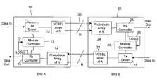
- FIG. 1is a block diagram illustrating two electro-optical modules according to an embodiment of the invention.
- a first electro-optical module 10 at end Ais connected, via a parallel optical ribbon 30 , to a second electro-optical module 20 at end B.
- the first electro-optical module 10comprises a VCSEL array 12 comprising N VCSELs arranged in parallel.
- a photodiode array 14comprising N photodiodes arranged in parallel.
- a module controller 13is further provided, as well as a receiver controller 16 , arranged to receive signals from the photodiode array.
- a transmitter driver 11which controls the VCSEL array is also included.
- the transmitter driver 11is arranged to receive data in, in the form of an electrical signal, and to control the VCSEL to convert the electrical signal into an optical signal, which is transmitted via the parallel optical fiber 30 .
- the parallel optical signal received at the photodiode array 14is converted into an electrical signal and passed to the receiver controller 16 , and then output as an electrical data out signal.
- the overall operation of the electro-optical module to convert between the optical and electrical domainsis controlled by the module controller 13 , in a conventional manner.
- a loss of signal flag 15provided via the receiver controller to the module controller 13 .
- the loss of signal flagindicates to the module controller that one of the receive lanes received by the photodiode array has lost an optical signal, in that no optical signal at all is being received thereon.
- the loss of signal flag 15also indicates to the module controller on which of the receive lanes i the loss of signal has occurred.
- the electro-optical module 20has a corresponding structure to the first electro-optical module 10 .
- the second electro-optical module 20comprises a photodiode array 24 , having N photodiodes arranged in parallel.
- the photodiode array 24feeds a signal to the receiver controller at 26 , which then outputs an electrical data out signal.
- a VCSEL arraycomprising N VCSEL lasers arranged in parallel.
- a transmitter driver circuit 21is arranged to receive an electrical data input signal, and to drive VCSEL array 22 so to produce a parallel optical signal, which is then output.
- the overall operation of the electro-optical module 20 to convert between the electrical and optical domainsis controlled by the module controller 23 , in a conventional manner.
- the photodiode array 24 of the second electro-optical module 20is coupled to the VCSEL array 12 of the first electro-optical module 10
- the VCSEL array 22 of the second electro-optical module 20is coupled to the photodiode array 14 of the first electro-optical module 10 .
- the couplingis performed by a parallel optical ribbon, in this case having 2N optical fibers.
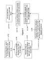
- step 2 . 2assume at step 2 . 2 that the electro optical modules are in normal operation, and that there are N active links in both directions i.e. from A to B, and B to A.
- the optical power in the parallel optical ribbon 30may exceed eye safe levels.
- the ith link in a particular directione.g. from A to B
- the laser light being transmitted on that linkis escaping from the optical fiber.
- the receiver controllerIn response to the detected loss of power, at step 2 . 8 the receiver controller asserts the loss of signal flag, and indicates on which receive lane the loss of signal has occurred to the module controller. In response, at step 2 . 10 the module controller signals the transmitter driver to put the corresponding transmit lane into an eye safe signaling mode. In this respect, as noted previously there are a corresponding number of transmit lanes and receive lanes in the first and second optical transceivers 10 and 20 . Therefore, for example, if the loss of signal has been detected on the third receive lane, then the module controller signals the transmitter driver to put the third transmit lane into an eye safe mode. More generally, where a loss of signal is detected on the ith receive lane, then the ith transmit lane is controlled so as to be put into an eye-safe signaling mode.
- the transmitter drivercontrols the VCSEL to render the corresponding transmit lane into an eye safe signaling mode, and at step 2 . 14 , the corresponding transmit lane transmits in the eye safe signaling mode.
- an electro-optical moduledetects a loss of signal on one of its receive lanes, it causes the corresponding transmit lane to transmit an eye safe signaling mode signal, which is preferably in a predetermined format. More particularly, according to a preferred embodiment the eye safe signal which is transmitted is a beacon type signal, in which the transmitter will turn on for a predetermined time, followed by a period where no light is emitted. The average power over a period of less than one second is arranged to be below the eye safety limit.
- FIG. 3illustrates the steps performed by the electro-optical module at the other end of the link, when the eye safe beacon signal is received.
- steps 3 . 2 and 3 . 4are identical to steps 2 . 2 and 2 . 4 described previously.
- the electro-optical module at the other end of the linki.e. the original receiver end
- the electro-optical module at the other end of the linkwill be transmitting the eye safe beacon signal on its transmit lane which corresponds to the receive lane at which it had detected a loss of signal.
- the receiver array at the original transmit enddetects the eye safe signal on its corresponding receive lane to the transmit lane on which it was originally transmitting, at step 3 . 6 .
- the receiver controllerindicates the detection of the eye safe signal on the particular receive lane to the module controller, at step 3 . 8 . Receipt of the eye safe signal on the receive lane tells the module controller that the corresponding transmit lane must have suffered a fault, such that the signal that it is transmitting thereon is not being received at the other end of the link.
- the module controllersignals the transmit controller to put the corresponding transmit lane into an eye safe mode itself.
- the transmit drivercontrols the VCSEL array to put the appropriate transmit lane into eye safe mode.
- the eye safe signalis preferably in the same format as the received eye safe signal. That is, a beacon signal wherein the average power of the beacon over the period of less than one second is below the eye safety limit.
- both of the ith transmit lanes transmitted from the electro-optical modules 10 and 20are transmitting in eye safe signaling mode, that is, transmitting a beacon signal at an eye safe power level.
- eye safe signaling modethat is, transmitting a beacon signal at an eye safe power level.
- the parallel optical fiber ribbonis repaired at step 4 . 4 .
- the eye safe signaling mode signal transmitted on the ith transmit lane from the original transmit endis received on the ith receive lane of the receiver end electro optical transceiver, at step 4 . 6 .
- the receiver controller at the receiver end electro optical transceiverindicates this fact to the module controller, which then passes a control signal to the transmitter driver of the transceiver, to indicate that normal operation of the ith transmit lane may resume.
- normal transmission operation on the ith transmit lanemay resume.
- the photodiode array at the original transmit end electro-optical transceiverdetects that normal transmission is occurring on its ith receive lane, whereas previously it was receiving the eye safe beaconing signal. In such a situation the resumption of normal operation on a receive lane which was previously beaconing in eyesafe mode indicates that the fiber link must have been repaired, and hence the original transmit end transceiver understands that normal transmission may be resumed on it's ith transmit lane. Thus, the module controller at the original transmit end transceiver controls the transmitter driver to cause the ith transmit lane to resume normal operation. Once this has occurred, then the link has been re-established in both directions.
- both of the transceivershave all their transmit lanes in eye safe beaconing mode.
- optical powercan be in the form of a beaconing signal, or because the transceiver at the other end has commenced normal transmit operations, and hence a normal information carrying optical signal.
- the ability to commence normal transmission on a lane immediately after receipt of a normal transmission being received on the corresponding receive lanemeans that the start-up procedure in both directions in shortened, as for any transmit and receive lane pair it is only necessary to wait for the beacon signal from one end, then both directions are enabled.
- the beacon signalhas a long duty cycle (i.e. is off for a relatively long time)
- transmissioncould start occurring in one direction a relatively long time before the other direction, if it was necessary to wait for a beacon signal from both ends.
- each transmit laneis “paired” with a receive lane, even if more than one transmit lane/receive lane is paired with the same receive lane/transmit lane.
- transmit lane iis, paired with receive lanes 2i and 2i+1, whereas at end B receive lane i is paired with transmit lanes 2i and 2i+1.
- lane i from A to Bbreaks, then the loss of signal is detected at the receiver array at transceiver B, and one of transmit lanes 2i and 2i+1 from B to A is caused to enter the eyesafe signaling mode, to signal the breakage to transceiver A so that transceiver A can control the its own transmit lane on the broken fiber to render it eye-safe.
- one of the lanes from B to Acan stay open.
- transceiver Asignals this to transceiver B by causing its own transmit lane i to enter the eyesafe signaling mode.
- transceiver Bdoes not know which of the two transmit lanes is broken, and hence must put them both into eye safe mode. Nevertheless, eye safe operation is still guaranteed, whilst the remainder of the transmission lanes in both directions which remain unaffected can remain in operation.
- multiple transmit lanesare “paired” with multiple receive lanes.
- a group of transmit lanes 1 to jis paired with receiver lanes 1 to j, where j is an integer less than N, where N is the total number of transmit lanes (or receive lanes).
- Nis the total number of transmit lanes (or receive lanes).
- the embodiments of the inventionallow parallel optical links to be controlled substantially on a per lane basis, by pairing transmit and receive lanes, such that if a loss of power is detected on a receive lane, the corresponding transmit lane can be used as a signaling lane to tell the transmitter at the other end of the link to go into an eye-safe transmission mode.
- other transmission and receive lane pairs on the linkremain unaffected, and can continue with normal operation. Hence, the entire link is not lost by breakage in only a subset of the fiber links.
- the foregoing techniquesmay be performed by, for example, an optical signal processor, a single central processor, a multiprocessor, one or more digital signal processors, gate arrays of logic gates, or hardwired logic circuits for executing a sequence of signals or program of instruction to perform functions of the invention by operating on input data and generating output.
- the methodsmay advantageously be implements in one or more computer programs that are executable on a programmable system including at least one programmable processor coupled to receive data and instructions from, and to transmit data and instructions to, a data storage system, at least one in/out device, and at least one output device.
- Each computer programmay be implemented in a high-level procedural or object-oriented programming language, or in assembly or machine language if desired; and in any case, the language may be complied or interpreted language.
- Suitable processorsinclude, by way of example, both general and special purpose microprocessors. Generally, a processor will receive instructions and data from read-only memory and/or random access memory.
- Storage devices suitable for tangibly embodying computer program instructions and datainclude all forms of non-volatile memory, including by way of example, semiconductor devices, such as EPROM, EEPROM, and flash memory devices; magnetic disks such as internal hard disks and removable disks; magneto-optical disks; and CD-ROM disks. Any of the foregoing may be supplemented by or incorporated in, specially designed application-specific integrated circuits (ASICS).
- ASICSapplication-specific integrated circuits
Landscapes
- Physics & Mathematics (AREA)
- Electromagnetism (AREA)
- Engineering & Computer Science (AREA)
- Computer Networks & Wireless Communication (AREA)
- Signal Processing (AREA)
- Optical Communication System (AREA)
Abstract
Description
Claims (20)
Priority Applications (2)
| Application Number | Priority Date | Filing Date | Title |
|---|---|---|---|
| US11/732,996US7787767B2 (en) | 2007-04-05 | 2007-04-05 | Eye safety in electro-optical transceivers |
| US11/836,519US7581891B2 (en) | 2004-10-15 | 2007-08-09 | Laser adjustment in integrated optoelectronic modules/fiber optic cables |
Applications Claiming Priority (1)
| Application Number | Priority Date | Filing Date | Title |
|---|---|---|---|
| US11/732,996US7787767B2 (en) | 2007-04-05 | 2007-04-05 | Eye safety in electro-optical transceivers |
Related Child Applications (2)
| Application Number | Title | Priority Date | Filing Date |
|---|---|---|---|
| US10/965,984Continuation-In-PartUS7575380B2 (en) | 2004-10-15 | 2004-10-15 | Integrated optical fiber and electro-optical converter |
| US11/836,519Continuation-In-PartUS7581891B2 (en) | 2004-10-15 | 2007-08-09 | Laser adjustment in integrated optoelectronic modules/fiber optic cables |
Publications (2)
| Publication Number | Publication Date |
|---|---|
| US20080247752A1 US20080247752A1 (en) | 2008-10-09 |
| US7787767B2true US7787767B2 (en) | 2010-08-31 |
Family
ID=39827004
Family Applications (1)
| Application Number | Title | Priority Date | Filing Date |
|---|---|---|---|
| US11/732,996Active2028-11-23US7787767B2 (en) | 2004-10-15 | 2007-04-05 | Eye safety in electro-optical transceivers |
Country Status (1)
| Country | Link |
|---|---|
| US (1) | US7787767B2 (en) |
Cited By (11)
| Publication number | Priority date | Publication date | Assignee | Title |
|---|---|---|---|---|
| US20100028004A1 (en)* | 2008-08-01 | 2010-02-04 | Masaru Nishino | Optical communication device, optical communication system, optical output control method and program |
| US20110013905A1 (en)* | 2009-07-17 | 2011-01-20 | Avago Technologies Fiber Ip (Singapore) Pte. Ltd. | Active optical cable apparatus and method for detecting optical fiber breakage |
| US20140133846A1 (en)* | 2012-03-27 | 2014-05-15 | Miaobin Gao | Optical link handshake techniques and configurations |
| US9232592B2 (en) | 2012-04-20 | 2016-01-05 | Trilumina Corp. | Addressable illuminator with eye-safety circuitry |
| US10038304B2 (en) | 2009-02-17 | 2018-07-31 | Trilumina Corp. | Laser arrays for variable optical properties |
| US10244181B2 (en) | 2009-02-17 | 2019-03-26 | Trilumina Corp. | Compact multi-zone infrared laser illuminator |
| US10393521B2 (en) | 2016-10-13 | 2019-08-27 | Stanley Black & Decker Inc. | Laser line generating device |
| US10615871B2 (en) | 2009-02-17 | 2020-04-07 | Trilumina Corp. | High speed free-space optical communications |
| US10778329B1 (en) | 2019-03-26 | 2020-09-15 | Ciena Corporation | Multi-fiber interface automatic power reduction systems and methods |
| US11095365B2 (en) | 2011-08-26 | 2021-08-17 | Lumentum Operations Llc | Wide-angle illuminator module |
| US12288960B2 (en)* | 2020-10-08 | 2025-04-29 | Quanta Computer Inc. | Method and system for control of laser emissions for safety |
Families Citing this family (6)
| Publication number | Priority date | Publication date | Assignee | Title |
|---|---|---|---|---|
| CN101660943A (en)* | 2009-09-29 | 2010-03-03 | 中兴通讯股份有限公司 | Optical power detection device and working method thereof |
| US8576382B2 (en) | 2011-03-22 | 2013-11-05 | Exelis, Inc. | Method and apparatus for controlling laser transmissions for enhanced safety |
| US9287991B2 (en)* | 2012-10-17 | 2016-03-15 | Christie Digital Systems Usa, Inc. | Light module interlock system |
| US9391698B1 (en)* | 2013-10-23 | 2016-07-12 | Google Inc. | Systems and methods for achieving improved eye safety of an optical transceiver |
| US9413454B1 (en)* | 2014-06-30 | 2016-08-09 | Juniper Networks, Inc. | Automatic bandwidth adjustment on multi-fiber optics |
| CN114791653A (en)* | 2015-03-24 | 2022-07-26 | 申泰公司 | Optical block with textured surface |
Citations (6)
| Publication number | Priority date | Publication date | Assignee | Title |
|---|---|---|---|---|
| US5515361A (en)* | 1995-02-24 | 1996-05-07 | International Business Machines Corporation | Link monitoring and management in optical star networks |
| US20020149810A1 (en) | 2001-02-09 | 2002-10-17 | International Business Machines Corporation | Laser safety method for DC coupled parallel optical link |
| US20030095303A1 (en) | 2001-11-16 | 2003-05-22 | Cunningham David G. | Open fiber control for optical transceivers |
| US7062177B1 (en)* | 2002-06-25 | 2006-06-13 | Cypress Semiconductor Corp. | Out of band communications link for 4-lane optical modules using dark fibers and low-bandwidth LEDs |
| US7248797B2 (en)* | 2000-09-29 | 2007-07-24 | Transmode Systems Ab | Transmitter-receiver device and a communication system |
| US7529488B2 (en)* | 2001-02-05 | 2009-05-05 | Finisar Corporation | Optical transceiver module with onboard diagnostics accessible via pins |
- 2007
- 2007-04-05USUS11/732,996patent/US7787767B2/enactiveActive
Patent Citations (6)
| Publication number | Priority date | Publication date | Assignee | Title |
|---|---|---|---|---|
| US5515361A (en)* | 1995-02-24 | 1996-05-07 | International Business Machines Corporation | Link monitoring and management in optical star networks |
| US7248797B2 (en)* | 2000-09-29 | 2007-07-24 | Transmode Systems Ab | Transmitter-receiver device and a communication system |
| US7529488B2 (en)* | 2001-02-05 | 2009-05-05 | Finisar Corporation | Optical transceiver module with onboard diagnostics accessible via pins |
| US20020149810A1 (en) | 2001-02-09 | 2002-10-17 | International Business Machines Corporation | Laser safety method for DC coupled parallel optical link |
| US20030095303A1 (en) | 2001-11-16 | 2003-05-22 | Cunningham David G. | Open fiber control for optical transceivers |
| US7062177B1 (en)* | 2002-06-25 | 2006-06-13 | Cypress Semiconductor Corp. | Out of band communications link for 4-lane optical modules using dark fibers and low-bandwidth LEDs |
Cited By (24)
| Publication number | Priority date | Publication date | Assignee | Title |
|---|---|---|---|---|
| US20100028004A1 (en)* | 2008-08-01 | 2010-02-04 | Masaru Nishino | Optical communication device, optical communication system, optical output control method and program |
| US8190023B2 (en)* | 2008-08-01 | 2012-05-29 | Nec Corporation | Optical communication device, optical communication system, optical output control method and program |
| US10038304B2 (en) | 2009-02-17 | 2018-07-31 | Trilumina Corp. | Laser arrays for variable optical properties |
| US10615871B2 (en) | 2009-02-17 | 2020-04-07 | Trilumina Corp. | High speed free-space optical communications |
| US11075695B2 (en) | 2009-02-17 | 2021-07-27 | Lumentum Operations Llc | Eye-safe optical laser system |
| US10244181B2 (en) | 2009-02-17 | 2019-03-26 | Trilumina Corp. | Compact multi-zone infrared laser illuminator |
| US11405105B2 (en) | 2009-02-17 | 2022-08-02 | Lumentum Operations Llc | System for optical free-space transmission of a string of binary data |
| US11121770B2 (en) | 2009-02-17 | 2021-09-14 | Lumentum Operations Llc | Optical laser device |
| US10938476B2 (en) | 2009-02-17 | 2021-03-02 | Lumentum Operations Llc | System for optical free-space transmission of a string of binary data |
| CN101958748A (en)* | 2009-07-17 | 2011-01-26 | 安华高科技光纤Ip(新加坡)私人有限公司 | Active fiber optic cable plant and the method that is used for the detection fiber breakage |
| US20110013905A1 (en)* | 2009-07-17 | 2011-01-20 | Avago Technologies Fiber Ip (Singapore) Pte. Ltd. | Active optical cable apparatus and method for detecting optical fiber breakage |
| US11451013B2 (en) | 2011-08-26 | 2022-09-20 | Lumentum Operations Llc | Wide-angle illuminator module |
| US11095365B2 (en) | 2011-08-26 | 2021-08-17 | Lumentum Operations Llc | Wide-angle illuminator module |
| US20140133846A1 (en)* | 2012-03-27 | 2014-05-15 | Miaobin Gao | Optical link handshake techniques and configurations |
| US9112601B2 (en)* | 2012-03-27 | 2015-08-18 | Intel Corporation | Optical link handshake techniques and configurations |
| US9232592B2 (en) | 2012-04-20 | 2016-01-05 | Trilumina Corp. | Addressable illuminator with eye-safety circuitry |
| US10989533B2 (en) | 2016-10-13 | 2021-04-27 | Stanley Black & Decker Inc. | Laser line generating device |
| US10393521B2 (en) | 2016-10-13 | 2019-08-27 | Stanley Black & Decker Inc. | Laser line generating device |
| US11815353B2 (en) | 2016-10-13 | 2023-11-14 | Stanley Black & Decker Inc. | Laser line generating device |
| CN112106312A (en)* | 2019-03-26 | 2020-12-18 | 希尔纳公司 | Multi-fiber interface automatic power reduction system and method |
| WO2020198294A1 (en)* | 2019-03-26 | 2020-10-01 | Ciena Corporation | Multi-fiber interface automatic power reduction systems and methods |
| US10778329B1 (en) | 2019-03-26 | 2020-09-15 | Ciena Corporation | Multi-fiber interface automatic power reduction systems and methods |
| CN112106312B (en)* | 2019-03-26 | 2022-12-23 | 希尔纳公司 | Multi-fiber interface automatic power reduction system and method |
| US12288960B2 (en)* | 2020-10-08 | 2025-04-29 | Quanta Computer Inc. | Method and system for control of laser emissions for safety |
Also Published As
| Publication number | Publication date |
|---|---|
| US20080247752A1 (en) | 2008-10-09 |
Similar Documents
| Publication | Publication Date | Title |
|---|---|---|
| US7787767B2 (en) | Eye safety in electro-optical transceivers | |
| US7092630B2 (en) | Open fiber control for optical transceivers | |
| US7072582B2 (en) | Optical transmitter power setting using feedback | |
| US7860399B2 (en) | Host-independent link validation between optical communications modules | |
| US20110013905A1 (en) | Active optical cable apparatus and method for detecting optical fiber breakage | |
| US8139951B2 (en) | Fiber-optic long-haul transmission system | |
| EP0850514B1 (en) | System, method and device for monitoring a fiber optic cable | |
| US20050201761A1 (en) | SINGLE FIBER TRANSCEIVER with FAULT LOCALIZATION | |
| KR101647336B1 (en) | Method and apparatus for suppressing pcie noise output in optical fiber communications, and communications node | |
| JPH06204948A (en) | Device and method of fail-safe automatic interruption for high-output light communication system | |
| US20240014896A1 (en) | Optical splitting apparatus, optical splitting system, passive optical network, and optical fiber fault detection method | |
| US20210247578A1 (en) | Power over fiber system and data communication devices | |
| JP4044560B2 (en) | Optical transmission line failure detection system | |
| US6658030B1 (en) | Laser safety method and device for duplex open loop parallel optical link | |
| EP1309109B1 (en) | Apparatus and method for monitoring an optical transmission line | |
| AU672631B2 (en) | Optical communication system | |
| CN113285750B (en) | Fault diagnosis method for optical fiber communication equipment and power communication network | |
| JPH10224299A (en) | Optical signal output monitor circuit for optical transmitter | |
| US20240214065A1 (en) | Fault locating method for optical network and related device | |
| CN119276348B (en) | Optical fiber line detection device, optical fiber line detection method, electronic equipment and storage medium | |
| AU612247B2 (en) | Supervision in glass fibre duplex transmission systems | |
| US20020036767A1 (en) | Method for monitoring an optical waveguide, as well as monitoring system and monitoring unit for said method | |
| US20040001721A1 (en) | Methods and apparatus for monitoring optical transmissions | |
| WO2023223572A1 (en) | Communication device, optical power supply system, and optical power supply method | |
| US6845189B2 (en) | System and a method for limiting the maximum of light transmitted from a ribbon fiber |
Legal Events
| Date | Code | Title | Description |
|---|---|---|---|
| AS | Assignment | Owner name:EMCORE CORPORATION, NEW JERSEY Free format text:ASSIGNMENT OF ASSIGNORS INTEREST;ASSIGNOR:WANG, XIAOZHONG;REEL/FRAME:019212/0035 Effective date:20070402 | |
| AS | Assignment | Owner name:BANK OF AMERICA, N.A., ILLINOIS Free format text:SECURITY AGREEMENT;ASSIGNOR:EMCORE CORPORATION;REEL/FRAME:021824/0019 Effective date:20080926 Owner name:BANK OF AMERICA, N.A.,ILLINOIS Free format text:SECURITY AGREEMENT;ASSIGNOR:EMCORE CORPORATION;REEL/FRAME:021824/0019 Effective date:20080926 | |
| STCF | Information on status: patent grant | Free format text:PATENTED CASE | |
| AS | Assignment | Owner name:EMCORE SOLAR POWER, INC., NEW MEXICO Free format text:RELEASE BY SECURED PARTY;ASSIGNOR:BANK OF AMERICA, N.A.;REEL/FRAME:027050/0880 Effective date:20110831 Owner name:EMCORE CORPORATION, NEW MEXICO Free format text:RELEASE BY SECURED PARTY;ASSIGNOR:BANK OF AMERICA, N.A.;REEL/FRAME:027050/0880 Effective date:20110831 | |
| AS | Assignment | Owner name:EMCORE SOLAR POWER, INC., NEW MEXICO Free format text:PARTIAL RELEASE OF SECURITY INTEREST;ASSIGNOR:WELLS FARGO BANK, NATIONAL ASSOCIATION;REEL/FRAME:028192/0189 Effective date:20120507 Owner name:EMCORE CORPORATION, NEW MEXICO Free format text:PARTIAL RELEASE OF SECURITY INTEREST;ASSIGNOR:WELLS FARGO BANK, NATIONAL ASSOCIATION;REEL/FRAME:028192/0189 Effective date:20120507 | |
| FEPP | Fee payment procedure | Free format text:PAYOR NUMBER ASSIGNED (ORIGINAL EVENT CODE: ASPN); ENTITY STATUS OF PATENT OWNER: LARGE ENTITY | |
| AS | Assignment | Owner name:SUMITOMO ELECTRIC DEVICE INNOVATIONS, U.S.A., INC. Free format text:ASSIGNMENT OF ASSIGNORS INTEREST;ASSIGNOR:EMCORE CORPORATION;REEL/FRAME:030006/0126 Effective date:20130225 | |
| FPAY | Fee payment | Year of fee payment:4 | |
| MAFP | Maintenance fee payment | Free format text:PAYMENT OF MAINTENANCE FEE, 8TH YEAR, LARGE ENTITY (ORIGINAL EVENT CODE: M1552) Year of fee payment:8 | |
| MAFP | Maintenance fee payment | Free format text:PAYMENT OF MAINTENANCE FEE, 12TH YEAR, LARGE ENTITY (ORIGINAL EVENT CODE: M1553); ENTITY STATUS OF PATENT OWNER: LARGE ENTITY Year of fee payment:12 |