US7787419B2 - System and method for providing a mesh network using a plurality of wireless access points (WAPs) - Google Patents
System and method for providing a mesh network using a plurality of wireless access points (WAPs)Download PDFInfo
- Publication number
- US7787419B2 US7787419B2US10/606,565US60656503AUS7787419B2US 7787419 B2US7787419 B2US 7787419B2US 60656503 AUS60656503 AUS 60656503AUS 7787419 B2US7787419 B2US 7787419B2
- Authority
- US
- United States
- Prior art keywords
- access point
- cell
- wireless access
- signal
- mesh network
- Prior art date
- Legal status (The legal status is an assumption and is not a legal conclusion. Google has not performed a legal analysis and makes no representation as to the accuracy of the status listed.)
- Expired - Fee Related, expires
Links
Images


Classifications
- H—ELECTRICITY
- H04—ELECTRIC COMMUNICATION TECHNIQUE
- H04L—TRANSMISSION OF DIGITAL INFORMATION, e.g. TELEGRAPHIC COMMUNICATION
- H04L47/00—Traffic control in data switching networks
- H04L47/10—Flow control; Congestion control
- H04L47/12—Avoiding congestion; Recovering from congestion
- H04L47/125—Avoiding congestion; Recovering from congestion by balancing the load, e.g. traffic engineering
- H—ELECTRICITY
- H04—ELECTRIC COMMUNICATION TECHNIQUE
- H04L—TRANSMISSION OF DIGITAL INFORMATION, e.g. TELEGRAPHIC COMMUNICATION
- H04L47/00—Traffic control in data switching networks
- H04L47/10—Flow control; Congestion control
- H04L47/15—Flow control; Congestion control in relation to multipoint traffic
- H—ELECTRICITY
- H04—ELECTRIC COMMUNICATION TECHNIQUE
- H04L—TRANSMISSION OF DIGITAL INFORMATION, e.g. TELEGRAPHIC COMMUNICATION
- H04L47/00—Traffic control in data switching networks
- H04L47/10—Flow control; Congestion control
- H04L47/24—Traffic characterised by specific attributes, e.g. priority or QoS
- H—ELECTRICITY
- H04—ELECTRIC COMMUNICATION TECHNIQUE
- H04L—TRANSMISSION OF DIGITAL INFORMATION, e.g. TELEGRAPHIC COMMUNICATION
- H04L47/00—Traffic control in data switching networks
- H04L47/70—Admission control; Resource allocation
- H—ELECTRICITY
- H04—ELECTRIC COMMUNICATION TECHNIQUE
- H04L—TRANSMISSION OF DIGITAL INFORMATION, e.g. TELEGRAPHIC COMMUNICATION
- H04L47/00—Traffic control in data switching networks
- H04L47/70—Admission control; Resource allocation
- H04L47/76—Admission control; Resource allocation using dynamic resource allocation, e.g. in-call renegotiation requested by the user or requested by the network in response to changing network conditions
- H04L47/765—Admission control; Resource allocation using dynamic resource allocation, e.g. in-call renegotiation requested by the user or requested by the network in response to changing network conditions triggered by the end-points
- H04L47/767—Admission control; Resource allocation using dynamic resource allocation, e.g. in-call renegotiation requested by the user or requested by the network in response to changing network conditions triggered by the end-points after changing the attachment point, e.g. after hand-off
- H—ELECTRICITY
- H04—ELECTRIC COMMUNICATION TECHNIQUE
- H04L—TRANSMISSION OF DIGITAL INFORMATION, e.g. TELEGRAPHIC COMMUNICATION
- H04L47/00—Traffic control in data switching networks
- H04L47/70—Admission control; Resource allocation
- H04L47/82—Miscellaneous aspects
- H04L47/824—Applicable to portable or mobile terminals
- H—ELECTRICITY
- H04—ELECTRIC COMMUNICATION TECHNIQUE
- H04L—TRANSMISSION OF DIGITAL INFORMATION, e.g. TELEGRAPHIC COMMUNICATION
- H04L49/00—Packet switching elements
- H04L49/35—Switches specially adapted for specific applications
- H04L49/351—Switches specially adapted for specific applications for local area network [LAN], e.g. Ethernet switches
- H—ELECTRICITY
- H04—ELECTRIC COMMUNICATION TECHNIQUE
- H04L—TRANSMISSION OF DIGITAL INFORMATION, e.g. TELEGRAPHIC COMMUNICATION
- H04L67/00—Network arrangements or protocols for supporting network services or applications
- H04L67/01—Protocols
- H04L67/04—Protocols specially adapted for terminals or networks with limited capabilities; specially adapted for terminal portability
- H—ELECTRICITY
- H04—ELECTRIC COMMUNICATION TECHNIQUE
- H04L—TRANSMISSION OF DIGITAL INFORMATION, e.g. TELEGRAPHIC COMMUNICATION
- H04L67/00—Network arrangements or protocols for supporting network services or applications
- H04L67/14—Session management
- H—ELECTRICITY
- H04—ELECTRIC COMMUNICATION TECHNIQUE
- H04L—TRANSMISSION OF DIGITAL INFORMATION, e.g. TELEGRAPHIC COMMUNICATION
- H04L69/00—Network arrangements, protocols or services independent of the application payload and not provided for in the other groups of this subclass
- H04L69/40—Network arrangements, protocols or services independent of the application payload and not provided for in the other groups of this subclass for recovering from a failure of a protocol instance or entity, e.g. service redundancy protocols, protocol state redundancy or protocol service redirection
- H—ELECTRICITY
- H04—ELECTRIC COMMUNICATION TECHNIQUE
- H04W—WIRELESS COMMUNICATION NETWORKS
- H04W16/00—Network planning, e.g. coverage or traffic planning tools; Network deployment, e.g. resource partitioning or cells structures
- H04W16/14—Spectrum sharing arrangements between different networks
- H04W16/16—Spectrum sharing arrangements between different networks for PBS [Private Base Station] arrangements
- H—ELECTRICITY
- H04—ELECTRIC COMMUNICATION TECHNIQUE
- H04W—WIRELESS COMMUNICATION NETWORKS
- H04W28/00—Network traffic management; Network resource management
- H04W28/02—Traffic management, e.g. flow control or congestion control
- H04W28/10—Flow control between communication endpoints
- H04W28/12—Flow control between communication endpoints using signalling between network elements
- H—ELECTRICITY
- H04—ELECTRIC COMMUNICATION TECHNIQUE
- H04W—WIRELESS COMMUNICATION NETWORKS
- H04W28/00—Network traffic management; Network resource management
- H04W28/16—Central resource management; Negotiation of resources or communication parameters, e.g. negotiating bandwidth or QoS [Quality of Service]
- H04W28/18—Negotiating wireless communication parameters
- H04W28/20—Negotiating bandwidth
- H—ELECTRICITY
- H04—ELECTRIC COMMUNICATION TECHNIQUE
- H04W—WIRELESS COMMUNICATION NETWORKS
- H04W36/00—Hand-off or reselection arrangements
- H04W36/24—Reselection being triggered by specific parameters
- H04W36/30—Reselection being triggered by specific parameters by measured or perceived connection quality data
- H04W36/302—Reselection being triggered by specific parameters by measured or perceived connection quality data due to low signal strength
- H—ELECTRICITY
- H04—ELECTRIC COMMUNICATION TECHNIQUE
- H04W—WIRELESS COMMUNICATION NETWORKS
- H04W72/00—Local resource management
- H04W72/04—Wireless resource allocation
- H—ELECTRICITY
- H04—ELECTRIC COMMUNICATION TECHNIQUE
- H04W—WIRELESS COMMUNICATION NETWORKS
- H04W8/00—Network data management
- H04W8/02—Processing of mobility data, e.g. registration information at HLR [Home Location Register] or VLR [Visitor Location Register]; Transfer of mobility data, e.g. between HLR, VLR or external networks
- H04W8/04—Registration at HLR or HSS [Home Subscriber Server]
- H—ELECTRICITY
- H04—ELECTRIC COMMUNICATION TECHNIQUE
- H04L—TRANSMISSION OF DIGITAL INFORMATION, e.g. TELEGRAPHIC COMMUNICATION
- H04L1/00—Arrangements for detecting or preventing errors in the information received
- H04L1/12—Arrangements for detecting or preventing errors in the information received by using return channel
- H04L1/16—Arrangements for detecting or preventing errors in the information received by using return channel in which the return channel carries supervisory signals, e.g. repetition request signals
- H04L1/1607—Details of the supervisory signal
- H—ELECTRICITY
- H04—ELECTRIC COMMUNICATION TECHNIQUE
- H04L—TRANSMISSION OF DIGITAL INFORMATION, e.g. TELEGRAPHIC COMMUNICATION
- H04L69/00—Network arrangements, protocols or services independent of the application payload and not provided for in the other groups of this subclass
- H04L69/30—Definitions, standards or architectural aspects of layered protocol stacks
- H04L69/32—Architecture of open systems interconnection [OSI] 7-layer type protocol stacks, e.g. the interfaces between the data link level and the physical level
- H04L69/322—Intralayer communication protocols among peer entities or protocol data unit [PDU] definitions
- H04L69/329—Intralayer communication protocols among peer entities or protocol data unit [PDU] definitions in the application layer [OSI layer 7]
- H—ELECTRICITY
- H04—ELECTRIC COMMUNICATION TECHNIQUE
- H04W—WIRELESS COMMUNICATION NETWORKS
- H04W84/00—Network topologies
- H04W84/02—Hierarchically pre-organised networks, e.g. paging networks, cellular networks, WLAN [Wireless Local Area Network] or WLL [Wireless Local Loop]
- H04W84/10—Small scale networks; Flat hierarchical networks
- H04W84/12—WLAN [Wireless Local Area Networks]
- H—ELECTRICITY
- H04—ELECTRIC COMMUNICATION TECHNIQUE
- H04W—WIRELESS COMMUNICATION NETWORKS
- H04W84/00—Network topologies
- H04W84/18—Self-organising networks, e.g. ad-hoc networks or sensor networks
- H—ELECTRICITY
- H04—ELECTRIC COMMUNICATION TECHNIQUE
- H04W—WIRELESS COMMUNICATION NETWORKS
- H04W88/00—Devices specially adapted for wireless communication networks, e.g. terminals, base stations or access point devices
- H04W88/08—Access point devices
- H—ELECTRICITY
- H04—ELECTRIC COMMUNICATION TECHNIQUE
- H04W—WIRELESS COMMUNICATION NETWORKS
- H04W92/00—Interfaces specially adapted for wireless communication networks
- H04W92/16—Interfaces between hierarchically similar devices
- H04W92/20—Interfaces between hierarchically similar devices between access points
Definitions
- Embodiments of the present applicationrelate generally to hybrid wired/wireless networking, and more particularly to a method and system for providing a mesh network using a plurality of wireless access points.
- FIG. 1 ais a block diagram 100 of the OSI model. Referring to FIG.
- the OSI modelhas seven distinct functional layers including layer 7 , an application layer 114 ; layer 6 , a presentation layer 112 ; layer 5 , a session layer 110 ; layer 4 , a transport layer 108 , layer 3 , a network layer 106 ; layer 2 : a data link layer 104 ; and layer 1 , a physical layer 102 .
- the physical layer 102may further include a physical layer convergence procedure (PLCP) sublayer 102 b and a physical media dependent sublayer 102 a .
- the data link layer 104may also include a Medium access control (MAC) layer 104 a.
- MACMedium access control
- each OSI layerdescribes certain tasks which are necessary for facilitating the transfer of information through interfacing layers and ultimately through the network. Notwithstanding, the OSI model does not describe any particular implementation of the various layers.
- OSI layers 1 to 4generally handle network control and data transmission and reception, generally referred to as end-to-end network services. Layers 5 to 7 handle application issues, generally referred to as application services. Specific functions of each layer may vary depending on factors such as protocol and/or interface requirements or specifications that are necessary for implementation of a particular layer.
- the Ethernet protocolmay provide collision detection and carrier sensing in the physical layer.
- Layer 1the physical layer 102 , is responsible for handling all electrical, optical, opto-electrical and mechanical requirements for interfacing to the communication media.
- the physical layer 102may facilitate the transfer of electrical signals representing an information bitstream.
- the physical layer 102may also provide services such as, encoding, decoding, synchronization, clock data recovery, and transmission and reception of bit streams.
- the PLCP layer 102 bmay be configured to adapt and map services provided by the physical layer 102 to the functions provided by the device specific PMD sublayer 102 a .
- the PLCP layer 102 bmay be adapted to map PHY sublayer service data units (PDSUs) into a suitable packet and/or framing format necessary for providing communication services between two or more entities communicating via the physical medium.
- the PMD layer 102 aspecifies the actual methodology and/or protocols which may be used for receiving and transmitting via the physical medium.
- the MAC sublayer 104 amay be adapted to provide, for example, any necessary drivers which may be utilized to access the functions and services provided by the PLCP sublayer 102 b . Accordingly, higher layer services may be adapted to utilize the services provided by the MAC sublayer 104 a with little or no dependence on the PMD sublayer 102 a.
- the 802.11is a suite of specifications promulgated by the Institute of Electrical and Electronics Engineers (IEEE), which provide communication standards for the MAC and physical (PHY) layer of the OSI model.
- IEEEInstitute of Electrical and Electronics Engineers
- the 801.11 standardalso provides communication standards for wired and wireless local area networks (WLANs). More specifically, the 802.11 standard specifies five (5) types of physical layers for WLANs. These include, frequency hopping spread spectrum (FHSS), direct sequence spread spectrum (DSSS), infrared (IR) communication, high rate direct sequence spread spectrum spread spectrum (HR-DSS) and orthogonal frequency division multiplexing (OFDM).
- FHSSfrequency hopping spread spectrum
- DSSSdirect sequence spread spectrum
- IRinfrared
- HR-DSShigh rate direct sequence spread spectrum spread spectrum
- OFDMorthogonal frequency division multiplexing
- the 802.11 standardalso provides a PLCP frame format for each of the specified PHY layers.
- Ethernet speedsbeing increased from about 1-2 megabit per second (Mbps), to 10 Mbps, to 100 Mbps, to 1 gigabit per second (Gbps) to 10 Gbps.
- 802.11b, 802.11a and 802.11gwhich have been adapted to facilitate the demands for increased data rates.
- the 802.1 ⁇ g standardfor example, provides a maximum data rate of about 54 Mbps at a transmitter/receiver range of 19 meters (m) in a frequency range of 2.4 GHz to 2.4835 GHz.
- the 802.11b standardfor example, provides a maximum data rate of about 11 Mbps at a transmitter/receiver range of 57 meters (m) in a frequency range of 2.4 GHz to 2.4835 GHz.
- the 802.11a standardfor example, may be adapted to provide a maximum data rate of about 54 Mbps at a transmitter/receiver range of 12 meters (m) in a 300 MHz segmented bandwidth ranging from 5.150 GHz to 5.350 GHz and from 5.725 GHz to 5.825 GHz.
- the 802.11 standardforms the basis of the other standards in the suite of specifications, and the 802.11b, 802.11a and 802.11g standards provide various enhancements and new features to their predecessor standards. Notwithstanding, there are certain elementary building blocks that are common to all the standards in the suite of specifications. For example, all the standards in the suite of specifications utilize the Ethernet protocol and utilize carrier sense multiple access with collision avoidance (CSMA/CA) for distribution coordination function (DCF) and point coordination function (PCF).
- CSMA/CAcarrier sense multiple access with collision avoidance
- DCFdistribution coordination function
- PCFpoint coordination function
- CSMA/CAutilizes a simple negotiation scheme to permit access to a communication medium. If a transmitting entity wishes to transmit information to a receiving entity, the transmitting entity may sense the communication medium for communication traffic. In a case where the communication medium is busy, the transmitting entity may desist from making a transmission and attempt transmission at a subsequent time. In a case where the communication transmission is not busy, then the transmitting entity may send information over the communication medium. Notwithstanding, there may be a case where two or more transmission entities sense that the communication medium is not busy and attempt transmission at the same instant. To avoid collisions and retransmissions, CSMA/CA or a ready to send (RTS) and clear to send (CTS) messaging scheme may be employed, for example.
- RTSready to send
- CTSclear to send
- the transmitting devicemay send a ready to send message to one or more receiving device. Subsequent to the receipt of the ready to send message, the receiving device may send a clear to send message. Upon receipt of the clear to send message by the transmitting device, the transmitting device may initiate transfer of data to the receiving device. Upon receiving packets or frames from the transmitting device, the receiving device may acknowledge the received frames.
- the 802.11b standardcommonly called Wi-Fi, which represents wireless fidelity, is backward compatible with its predecessor standard 802.11.
- 802.11utilizes phase-shift keying (PSK) as a modulation scheme
- 802.11butilizes a hybrid PSK scheme called complementary code keying (CCK).
- CCKpermits higher data rate and particularly less susceptible to interference effects such as multipath-propagation interference, the PSK.
- the 802.11a standardprovides wireless asynchronous transfer mode (ATM) support and is typically utilized in access hubs.
- 802.11autilizes orthogonal frequency-division multiplexing (OFDM) modulation/encoding scheme, which provides a maximum data rate 54 Mbps.
- OFDMorthogonal frequency-division multiplexing
- Orthogonal frequency-division multiplexingis a digital modulation technique which splits a signal into several narrowband channels, with each channel having a different frequency. Each narrowband channel is arranged so as to minimize the effects of crosstalk between the channels and symbols in the data stream.
- 802.11a equipmentSince equipment designed to provide support for 802.11a operates at frequencies in the ranges 5.150 GHz to 5.350 GHz and from 5.725 GHz to 5.825 GHz, 802.11a equipment will not interoperate with equipment designed to operate with the 802.11b standard which defines operation in the 2.4 to 2.4835 GHz frequency band.
- 802.11b standardwhich defines operation in the 2.4 to 2.4835 GHz frequency band.
- One major drawbackis that companies that have invested in 802.11b equipment and infrastructure may not readily upgrade their network without significant expenditure.
- the 802.11g standardwas developed as an extension to 802.11b standard.
- the 802.11g standardmay utilize a similar OFDM modulation scheme as the 802.11a standard and delivers speeds comparable with the 802.11a standard. Since 802.11g compatible equipment operates in the same portion of the electromagnetic spectrum as 802.11b compatible equipment, 802.11 g is backwards compatible with existing 802.11b WLAN infrastructures. Due to backward compatibility of 802.11g with 802.11b, it would be desirable to have an 802.11b compliant radio card capable of interfacing directly with an 802.11g compliant access point and also an 802.11g compliant radio card capable of interfacing directly with an 802.11b compliant access point.
- 802.11g compatible equipmentoperates in the 2.4 GHz to 2.4835 GHz frequency range
- a typical transmitted signalutilizes a bandwidth of approximately 22 MHz, about a third or 30% of the total allocated bandwidth. This limits the number of non-overlapping channels utilized by an 802.11g access point to three (3).
- 802.11bA similar scenario exists with 802.11b. Accordingly, many of the channel assignment and frequency reuse schemes associated with the 802.11b standard may be inherent in the 802.11g.
- RF interferencemay pose additional operational problems with 802.11b and 802.11g equipment designed to operate in the 2.4 GHz portion of the electromagnetic spectrum.
- the 2.4 GHz portion of the spectrumis an unlicensed region which has been utilized for some time and is crowded with potential interfering devices. Some of these devices include cordless telephone, microwave ovens, intercom systems and baby monitors. Other potential interfering devices may be Bluetooth devices. Accordingly, interference poses interference problems with the 802.11b and 802.11 g standards.
- 802.11a compatible equipmentutilizes eight non-overlapping channels, as compared to three non-overlapping channels utilized by 802.11b. Accordingly, 802.11a access points may be deployed in a more dense manner than, for example 802.11b compatible equipment. For example, up to twelve access points each having a different assigned frequency may be deployed in a given area without causing co-channel interference. Consequently, 802.11a may be particularly useful in overcoming some of the problems associated with channel assignment, especially in areas that may have a dense user population and where increased throughput may be critical. Notwithstanding, the higher operating frequency of 802.11a along with its shorter operating range, may significantly increase deployment cost since a larger number of access points are required to service a given service area.
- a method for providing a mesh network using a plurality of access pointsmay include the step of coupling a first access point located in a first cell to at least a second access point located in a second cell.
- Servicemay be initially provided to an access device by a first access point located in the first cell.
- the access devicemay be serviced by a second access point located in a second cell whenever a signal for the access device falls below a specified threshold level.
- the second cellmay be a neighboring cell, which may be located adjacent to the first cell.
- a first signalmay be transmitted from a first beamforming antenna to the second access point.
- the first beamforming antennamay be coupled to the first access point.
- a second signalmay be transmitted from a second beamforming antenna to the first access point.
- the second beamforming antennamay be coupled to the second access point.
- a path for facilitating transmission of the first signal between the first beamforming antenna and the second beamforming antennamay be an uplink channel.
- a path for facilitating transmission of the second signal between the second beamforming antenna and the first beamforming antennamay be a downlink channel.
- the uplink channel and the downlink channelmay be a backhaul channel.
- the first access point located in a first cellmay be coupled to a third access point located in the first cell. Accordingly, an access device may be serviced by a third access point located in the first cell whenever a signal level of the access device falls below a specified threshold level. Either of the first access point and the access device may be configured to determine when the signal of an access device falls below a specified threshold level.
- Another embodiment of the inventionmay provide a machine-readable storage, having stored thereon a computer program having at least one code section adapted to facilitate communication in a mesh network using a plurality of access devices, the at least one code section being executable by a machine for causing the machine to perform the steps described above.
- a mesh network using a plurality of access pointsmay include means for coupling a first access point located in a first cell to at least a second access point located in a second cell and means for providing service initially to at least one of a plurality of access devices by the a first access point located in the first cell.
- the inventionprovides a means for servicing an access device by a second access point located in the second cell whenever a signal for the access device falls below a specified threshold.
- the second cellmay be a neighboring cell located adjacent to the first cell.
- the systemmay further include a first beamforming antenna coupled to the first access point for transmitting a first signal from the first access point to the second access point.
- a second beamforming antenna coupled to the second access pointmay be adapted to transmitting a second signal from a second access point to the first access point.
- a path for facilitating transmission between a first beamforming antenna and the second beamforming antennamay be an uplink channel.
- a path for facilitating transmission between the second beamforming antenna and the first beamforming antennamay be a downlink channel.
- the uplink channel and the downlink channelmay be a backhaul channel.
- the systemmay further include means for coupling the first access point located in a first cell to at least a third access point located in the first cell.
- the systemmay further include means for servicing an access device by a third access point located in the first cell whenever a signal level corresponding to the access device falls below a specified threshold.
- Either of the first access point and/or an access devicemay include means for determining when a signal level corresponding to the access device falls below a specified threshold.
- FIG. 1 ais a block diagram of the OSI model.
- FIG. 1 bis a block diagram illustrating a general PLCP frame as defined by 802.11.
- FIG. 1 cis a block diagram illustrating a PLCP frame utilized by frequency hopping spread spectrum as defined by 802.11.
- FIG. 1 dis a block diagram illustrating a PLCP frame for direct sequence spread spectrum and high rate direct sequence spread spectrum as defined by 802.11.
- FIG. 1 eis a block diagram illustrating a PLCP frame for orthogonal frequency division multiplexing as defined by 802.11.
- FIG. 2is a block diagram of system for providing a mesh network using a plurality of wireless access points in accordance with an embodiment of the invention.
- FIG. 3Ais a block diagram of an inter-mesh network handoff in accordance with an embodiment of the invention.
- FIG. 3Bis a flow diagram illustrating exemplary steps for facilitating communication in a mesh network, such as the network of FIG. 3A , using a plurality of access points, in accordance with an embodiment of the invention.
- FIG. 4is a block diagram of an intra-mesh network handoff in accordance with an embodiment of the invention.
- FIG. 5is a block diagram of an exemplary system that utilizes beam forming in accordance with an embodiment of the invention.
- FIG. 6is a block diagram of a system for providing a mesh network in accordance with an embodiment of the invention.
- a method for providing a mesh network using a plurality of access pointsmay include the step of coupling a first access point located in a first cell to at least a second access point located in a second cell.
- Servicemay be initially provided to an access device by a first access point located in the first cell.
- the access devicemay be serviced by a second access point located in a second cell whenever a signal for the access device falls below a specified threshold level.
- the second cellmay be a neighboring cell, which may be located adjacent to the first cell.
- FIG. 1 bis a block diagram 120 illustrating a general PLCP frame as defined by 802.11.
- preamble 122may include synchronization (SYNC) data 122 a and synchronization delimiter 122 b .
- the PLCP header 124may include, for example PLCP signal field (PSF) 124 a , service data 124 b , length 124 c and other fields.
- PSFPLCP signal field
- the preamble 122may be dependent on the PHY.
- the SYNC data 122 amay include a unique bit stream that may be adapted to signal timing parameters such as the start of a frame.
- the SYNC data 122 ais used for bit synchronization and demodulation.
- the SYNC delimiter 122 bprovides frame timing information and may be adapted to delimit the end of synchronization information.
- the PLCP header 124may be adapted to contain information used for decoding the frame.
- the PSF 124 amay be adapted to include communication data rate information.
- the service data 124 bis generally reserved, but may be utilized to provide application specific functionality.
- the length 124 cmay be adapted to indicate the length of the MAC data 126 . In this regard, the length 124 c may be expressed in terms of the time required to transmit the MAC data 126 .
- FIG. 1 cis a block diagram 130 illustrating a PLCP frame utilized by frequency hopping spread spectrum as defined by 802.11.
- a SYNC data 132PLCP header 134 and PSDU 136 .
- the PLCP header 134may include, for example, PSDU length word (PLW) 134 a , PLCP signaling field (PSF) 134 b , header error check field or CRC 134 c and other fields.
- the PLW 134 amay specify the number of octets contained in the PSDU 136 .
- the PSF 134be may be 4-bits in length and may be used to denote the communication data rate.
- FIG. 1 dis a block diagram 140 illustrating a PLCP frame for direct sequence spread spectrum and high rate direct sequence spread spectrum (HR-DSS) as defined by 802.11.
- preamble 142may include synchronization (SYNC) data 142 a and synchronization delimiter 142 b .
- the PLCP header 144may include PLCP signal field (PSF) 144 a , service data 144 b , length 144 c , and CRC field 144 d .
- PSFPLCP signal field
- the SYNC data 142 amay be 128 bits as compared to 8 bits for SYNC data 132 a for frequency hopping spread spectrum.
- the CRC 144 dis 16 bits, which is similar to CRC 134 c for frequency hopping spread spectrum.
- FIG. 1 eis a block diagram 150 illustrating a PLCP frame for orthogonal frequency division multiplexing as defined by 802.11.
- preamble 152may include synchronization (SYNC) data 152 a and synchronization delimiter 152 b .
- the PLCP header 154may include length 154 a , PLCP signal field (PSF) 154 b , reserved field 154 c , parity 154 d , tail 154 e and service 154 f .
- PSFPLCP signal field
- the length 154 ais a 12-bit field that may be adapted to indicate the length of the frame.
- the PSF 154 bis a 4-bit field that may indicate a modulation scheme utilized and its associated coding rate of the PSDU. For example, the specification utilizes binary 1011 to represent 6 Mbps, 1111 to represent 9 Mbps, 1010 to represent 12 Mbps, 1110 to represent 18 Mbps, 1001 to represent 24 Mbps, 1011 to represent 36 Mbps, 1000 to represent 48 Mbps and finally, 1100 to represent the maximum standardized rate if 54 Mbps.
- the reserved field 154 cis a 1 bit field that is reserved for future use and may be adapted for application specific use.
- the parity field 154 dmay indicate odd or even parity.
- the tail field 154 eis a 6-bit field.
- the service field 154 fis a 16-bit field that may be adapted to indicate the type of service.
- FIG. 2is a block diagram of system 200 for providing a mesh network using a plurality of wireless access points (WAPs) in accordance with an embodiment of the invention.
- WAPswireless access points
- FIG. 2there is illustrated a plurality of cells 202 , 204 , 206 , 208 , 210 , 212 , 214 , 216 , 218 , 220 , 222 , 224 , with each cell containing an access point (AP) 202 a , 204 a , 206 a , 208 a , 210 a , 212 a , 214 a , 216 a , 218 a , 220 a , 222 a , 224 a , respectively.
- APaccess point
- Each cellmay represent a separate mesh network.
- cell 220may represent a first mesh network and cell 214 may represent a second mesh network.
- access point 202 amay be adapted to provide WLAN service within a coverage area indicated by cell 202 .
- access point 214 amay be adapted to provide WLAN service within a coverage area indicated by cell 214 .
- the range of an access point located within and serving a particular cellmay be extended by interconnecting or coupling neighboring and surrounding cells.
- Cell 202has six (6) neighboring cells, namely 204 , 206 , 214 , 216 , 218 , 224 .
- Each of the access points 204 a , 206 a , 214 a , 216 a , 218 a , 224 a located in the cells 204 , 206 , 214 , 216 , 218 , 224 respectively,may be adapted to provide WLAN service within a coverage area indicated by cell 204 , 206 , 214 , 216 , 218 , 224 , respectively.
- the coverage area of access point 202may be extended into any portion of any one or more of the neighboring cells 204 , 206 , 214 , 216 , 218 , 224 by coupling the access points 204 a , 206 a , 214 a , 216 a , 218 a , and 224 a , to access point 202 a .
- an access device located in any one of cells 202 , 204 , 206 , 214 a , 216 a , 218 a , 224may communicate with a device located in any one of the cells 202 , 204 , 206 , 214 , 216 , 218 , 224 .
- an access device located in cell 214 serviced by access point 214 amay communicate with an access device located in cell 202 which may be serviced by access point 202 a .
- an access device located in cell 216 serviced by access point 216 amay communicate with an access device located in cell 224 which may be serviced by access point 224 a.
- a mobile access devicemay actively roam from a first mesh network to a second mesh network. For example, an access device may move from a first mesh network represented by cell 216 into second mesh network represented by cell 202 .
- intra-mesh network and inter-mesh network hand-offmay be provided.
- inter-mesh network handoffan access device moving from a first cell representing a first mesh network may be handed off to a second cell representing a second mesh network.
- intra-mesh network handoffan access device being serviced by a first access point located within a particular cell may be handed off to a second access point located within the same particular cell.
- FIG. 3Ais a block diagram 300 of a inter-mesh network handoff in accordance with an embodiment of the invention.
- a first cell 302corresponding to a first mesh network having an access point AP 1 302 a and a second cell 304 corresponding to a second mesh network having an access point AP 2 304 a .
- Located in the first cellis an access device 306 .
- Inter-mesh handoffmay involve handoff from a first serving access point, for example access point 302 a, to a second access point, for example access point 304 a , both access points being located within different cells or on different mesh networks.
- an inter-mesh network handoffmay occur from access point 302 a to 304 a.
- access point 302 amay initially provide service to access device 306 which may be mobile within the cell 302 . However, as access device 306 migrates to the fringe of the cell 302 , a signal received from access point 302 a may fade until it reaches, for example, a handover threshold.
- the handover thresholdmay be dependent on one or more signal parameters such as the signal strength received from one or more of access point 302 a and access point 302 b .
- the access device 306may dynamically keep a record of the frequency and corresponding signal strength of any received channel it encounters. For example, the access device 306 may be adapted to actively scan a list of frequencies for available channels.
- the record of the frequency and corresponding signal strength of any received channelmay serve as a handoff candidate list.
- the access device 306may be adapted to select the best candidate for a handoff from the candidate list based on, for example, a channel having the strongest signal strength. In a case where the access device 306 determines that the best access point for a handoff is access point 304 a , then the access device may tune it transceiver to an available transmit and/or receive channel corresponding to the access point 304 a . At this point, the access point 304 a provides service to the access device 306 .
- FIG. 3Bis a flow diagram illustrating exemplary steps for facilitating communication in a mesh network, such as the network of FIG. 3A , using a plurality of access points, in accordance with an embodiment of the invention.
- AP 302 amay initially provide service to AD 306 .
- AD 306may dynamically keep a record (i.e., AD 306 generates and maintains such record) of the frequency and corresponding signal strength of any received channel it encounters. Such record of frequencies and signal strengths may serve as a handoff candidate list.
- AP 304 amay service AD 306 .
- FIG. 4is a block diagram 400 of an intra-mesh network handoff in accordance with an embodiment of the invention.
- cell 402corresponding to a mesh network having a first access point AP 1 402 a and a second access point AP 2 402 b .
- access device 406Located in cell 402 is an access device 406 .
- Intra-mesh handoffmay include handoff from a first serving access point to a second access point, both access points being located within the same cell or on the same mesh network.
- an intra-mesh network handoffmay occur from access point 402 a to 402 b which may both be located in the same mesh network or cell.
- access point 402 amay initially provide service to access device 406 which may be mobile within cell 402 . However, as access device 406 migrates away from access point 402 a and towards access point 402 b , a signal received from access point 402 a may fade until it reaches, for example, a handover threshold. Simultaneous with the fading of the signal received from access point 402 a , a signal having increasing signal strength may be received from access point 402 b . The access device 406 may dynamically keep a record of the frequency and corresponding signal strength of any received channel it encounters including the frequencies and signal strength for available channels of access point 402 b in its handoff candidate list.
- the access device 406may be adapted to select the best candidate for a handoff from the candidate list based on, for example, a channel having the strongest signal strength. In a case where the access device 406 determines that the best access point for a handoff is access point 402 b , then the access device 406 may tune its transceiver to an available transmit and/or receive channel corresponding to the access point 402 b . At this point, the access point 402 b provides service to the access device 406 .
- a client or access devicemay initiate dissociation when signal strength drops below a threshold level.
- the clientmay initiate re-association when a signal strength of the new access point is above a threshold level.
- the new access pointmay send a message to the current access point informing the switch of a possible association of the client with the new access point.
- the current access pointmay send a response to the new access point to handover session context data.
- the current access pointmay send, for example, a security block to the new access point.
- the new access pointmay acknowledge the receipt of the security block.
- the new access pointmay identify the new switch serving the access point of the move.
- the new switchmay notify the current switch of the re-association.
- the current switchmay respond to the new switch with switch filtering information.
- An access devicemay initiate disassociation when signal strength falls below a specified threshold.
- the access devicemay initiate re-association when signal strength of a new access point is above a certain threshold.
- the new access pointmay send a message to the current AP to announce its re-association.
- the current access pointmay send a response to the new access point to handover session context data.
- the session datamay be, for example, encryption data which may prevent re-authentication.
- the current access pointmay send a security block to the new access point.
- the new access pointmay acknowledge receipt.
- the new access pointmay notify a switch of the move.
- the switchmay transfer filtering information from one port to another.
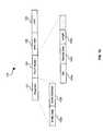
- FIG. 5is a block diagram of an exemplary system 500 that utilizes beam forming in accordance with an embodiment of the invention. Referring to FIG. 5 , there is shown a first cell 502 having an access point 502 a and an access device 502 b located therein. A second cell 504 may have an access point 504 a and an access device 504 b located therein.
- a beam forming antenna associated with access point 502 amay be adapted to provide communication with an access point 504 b .
- one or more transmit and receive frequenciesmay be assigned as communication channels to provide communication between access point 502 a and access point 504 a using the beam forming antenna path.
- the assigned channelsmay constitute a backbone channel 506 .
- the backbone channel 506may be adapted to utilize an 802.11b standard, while a mesh network 502 associated with access point 502 a and a mesh network 504 associated with access point 504 a may utilize an 802.11b or 802.1g standard.
- the backbone channelmay provide a communication path that may reduce interference with other channels in a particular cell, thereby increasing transmission throughput.
- a plurality of access devices located in cell 502may utilize channels other than those assigned to the backbone channel.
- a plurality of access devices located in cell 504may utilize channels other than those assigned to the backbone channel.
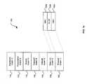
- FIG. 6is a block diagram of a system for providing a mesh network in accordance with an embodiment of the invention.
- a processor 604a transmitter 606 , an application block 608 , a database 610 and a receiver 612 .
- Processor 604 , transmitter 606 , application block 608 , database 610 and receiver 612may be variously coupled to processor 604 .
- the processor 604 , transmitter 606 and receiver 612may contain suitable logic and/or software that may be adapted to facilitate communication in a mesh network in accordance with the invention.
- FIG. 6may also include a beamforming antenna 614 .
- the beamforming antenna 614may include a plurality of receiver antenna elements and transmitter antenna elements. Accordingly, each of the plurality of receiver antenna elements and transmitter elements may be adapted to function as a beamforming antenna.
- Database 610may store applications and/or data that may be utilized by processor 606 .
- Processor 604under control of one or more applications such as application 608 , may be adapted to control transmitter 606 and receiver 608 to facilitate communication in a mesh network in accordance with an embodiment of the invention.
- Processor 604may be adapted to control communication over a first access point located in a first cell, which may be coupled to a second access point located in a second cell.
- the processor 604may be adapted to control receiver 612 and transmitter 606 to initially provide service to an access device by the first access point.
- the processor 604may be configured to determine when a signal level of an access device falls below a specified threshold level.
- a second processor similar to processor 604which may be associated with a second access point located within a second neighboring cell, may be configured to provide service to the access device. Accordingly, processor 604 may be adapted to terminate or discontinue serving the access device once the second processor starts to provide service to the access device.
- Processor 604may be adapted to control transmitter 606 to transmit a first signal from, for example, a first antenna element or sector of beamforming antenna 614 . Similarly, processor 604 may be adapted to control receiver 612 to receive a second signal that may be transmitted from a second beamforming antenna coupled to the second access point. Alternatively, processor 604 may be adapted to control transmitter 606 to transmit a first signal via a wired connection coupling the first and second access points. Similarly, processor 604 may be adapted to control receiver 612 to receive a second signal that may be transmitted from the second access point to the first access point via a wired connection.
- one or more of the PLCP frames illustrated in FIG. 1 b , FIG. 1 c , FIG. 1 d and FIG. 1 emay be adapted to contain information which may be utilized for providing communication between the plurality of access points in one or more mesh networks in accordance the embodiments of the invention. Additionally, the PLCP frames may be adapted to convey information for any one or more of the 801.11a, 802.11b and 802.11g modes of operation utilized by access points and/or access devices in accordance the embodiments of the invention.
- a method for providing a mesh network using a plurality of access pointsmay include the step of coupling a first access point located in a first cell to at least a second access point located in a second cell.
- Servicemay be initially provided to an access device by a first access point located in the first cell.
- the access devicemay be serviced by a second access point located in a second cell whenever a signal for the access device falls below a specified threshold level.
- the second cellmay be a neighboring cell, which may be located adjacent to the first cell.
- a first signalmay be transmitted from a first beamforming antenna to the second access point.
- the first beamforming antennamay be coupled to the first access point.
- a second signalmay be transmitted from a second beamforming antenna to the first access point.
- the second beamforming antennamay be coupled to the second access point.
- a path for facilitating transmission of the first signal between the first beamforming antenna and the second beamforming antennamay be an uplink channel.
- a path for facilitating transmission of the second signal between the second beamforming antenna and the first beamforming antennamay be a downlink channel.
- the uplink channel and the downlink channelmay be a backhaul channel.
- a backhaul link or channel between mesh network access pointsmay be utilizing a higher data rate protocol than the individual mesh networks or cells.
- the backhaul link or channelmay utilize 802.11a while the individual cell may utilize 802.11b or 802.11g.
- the backhaul channel or linkmay utilize long distance type wireless standards such as 802.16.
- the first access point located in a first cellmay be coupled to a third access point located in the first cell. Accordingly, an access device may be serviced by a third access point located in the first cell whenever a signal level of the access device falls below a specified threshold level. Either of the first access point and the access device may be configured to determine when the signal of an access device falls below a specified threshold level.
- the present inventionmay be realized in hardware, software, or a combination of hardware and software.
- the present inventionmay be realized in a centralized fashion in one computer system, or in a distributed fashion where different elements are spread across several interconnected computer systems. Any kind of computer system or other apparatus adapted for carrying out the methods described herein is suited.
- a typical combination of hardware and softwaremay be a general-purpose computer system with a computer program that, when being loaded and executed, controls the computer system such that it carries out the methods described herein.
- the present inventionalso may be embedded in a computer program product, which comprises all the features enabling the implementation of the methods described herein, and which when loaded in a computer system is able to carry out these methods.
- Computer program in the present contextmeans any expression, in any language, code or notation, of a set of instructions intended to cause a system having an information processing capability to perform a particular function either directly or after either or both of the following: a) conversion to another language, code or notation; b) reproduction in a different material form.
Landscapes
- Engineering & Computer Science (AREA)
- Computer Networks & Wireless Communication (AREA)
- Signal Processing (AREA)
- Quality & Reliability (AREA)
- Computer Security & Cryptography (AREA)
- Databases & Information Systems (AREA)
- Mobile Radio Communication Systems (AREA)
Abstract
Description
Claims (30)
Priority Applications (15)
| Application Number | Priority Date | Filing Date | Title |
|---|---|---|---|
| US10/606,565US7787419B2 (en) | 2002-09-17 | 2003-06-26 | System and method for providing a mesh network using a plurality of wireless access points (WAPs) |
| EP03752174AEP1543434B1 (en) | 2002-09-17 | 2003-09-09 | System for transfer of authentication during access device handover |
| PCT/US2003/028311WO2004027637A1 (en) | 2002-09-17 | 2003-09-09 | System for transfer of authentication during access device handover |
| EP03749502AEP1573949A4 (en) | 2002-09-17 | 2003-09-09 | SYSTEM AND METHOD FOR IMPLEMENTING A SUPERCANAL IN A MULTIPROTOCOL AND MULTIBAND WIRED / WIRELESS HYBRID NETWORK |
| EP08012489.4AEP1978710B1 (en) | 2002-09-17 | 2003-09-09 | System for transfer of authentication during access device handover |
| PCT/US2003/028058WO2004028057A2 (en) | 2002-09-17 | 2003-09-09 | System and method for providing a super channel in a multi-band multi-protocol hybrid wired/wireless network |
| EP03797889.7AEP1543433B1 (en) | 2002-09-17 | 2003-09-09 | A wireless access point in a hybrid wire/wireless network |
| PCT/US2003/028136WO2004027635A1 (en) | 2002-09-17 | 2003-09-09 | A wireless access point in a hybrid wire/wireless network |
| EP03021047.0AEP1401151B1 (en) | 2002-09-17 | 2003-09-17 | System and method for providing a mesh network using a plurality of wireless access points (WAPs) |
| EP04010593AEP1492273A3 (en) | 2003-06-26 | 2004-05-04 | Method for providing seamless connectivity and communication in a multi-band multi-protocol hybrid/wireless network |
| EP04010591.8AEP1492272B1 (en) | 2003-06-26 | 2004-05-04 | Method for providing a wireless access point (WAP) having multiple integrated transceiver devices for use in a hybrid wired/wireless network |
| EP20040011698EP1492274B1 (en) | 2003-06-26 | 2004-05-17 | Method for providing a mesh network using a plurality of wireless access points (WAPS) |
| EP04012806.8AEP1492275B1 (en) | 2003-06-26 | 2004-05-28 | System and method for providing a super channel in a multi-band multi-protocol hybrid wired/wireless network |
| US12/872,141US8537780B2 (en) | 2002-09-17 | 2010-08-31 | System and method for providing a mesh network using a plurality of wireless access points (WAPs) |
| US13/966,883US20130329676A1 (en) | 2002-09-17 | 2013-08-14 | SYSTEM AND METHOD FOR PROVIDING A MESH NETWORK USING A PLURALITY OF WIRELESS ACCESS POINTS (WAPs) |
Applications Claiming Priority (5)
| Application Number | Priority Date | Filing Date | Title |
|---|---|---|---|
| US41130102P | 2002-09-17 | 2002-09-17 | |
| US41126102P | 2002-09-17 | 2002-09-17 | |
| US43309402P | 2002-12-13 | 2002-12-13 | |
| US43598402P | 2002-12-20 | 2002-12-20 | |
| US10/606,565US7787419B2 (en) | 2002-09-17 | 2003-06-26 | System and method for providing a mesh network using a plurality of wireless access points (WAPs) |
Related Child Applications (1)
| Application Number | Title | Priority Date | Filing Date |
|---|---|---|---|
| US12/872,141ContinuationUS8537780B2 (en) | 2002-09-17 | 2010-08-31 | System and method for providing a mesh network using a plurality of wireless access points (WAPs) |
Publications (2)
| Publication Number | Publication Date |
|---|---|
| US20040114546A1 US20040114546A1 (en) | 2004-06-17 |
| US7787419B2true US7787419B2 (en) | 2010-08-31 |
Family
ID=31950776
Family Applications (3)
| Application Number | Title | Priority Date | Filing Date |
|---|---|---|---|
| US10/606,565Expired - Fee RelatedUS7787419B2 (en) | 2002-09-17 | 2003-06-26 | System and method for providing a mesh network using a plurality of wireless access points (WAPs) |
| US12/872,141Expired - LifetimeUS8537780B2 (en) | 2002-09-17 | 2010-08-31 | System and method for providing a mesh network using a plurality of wireless access points (WAPs) |
| US13/966,883AbandonedUS20130329676A1 (en) | 2002-09-17 | 2013-08-14 | SYSTEM AND METHOD FOR PROVIDING A MESH NETWORK USING A PLURALITY OF WIRELESS ACCESS POINTS (WAPs) |
Family Applications After (2)
| Application Number | Title | Priority Date | Filing Date |
|---|---|---|---|
| US12/872,141Expired - LifetimeUS8537780B2 (en) | 2002-09-17 | 2010-08-31 | System and method for providing a mesh network using a plurality of wireless access points (WAPs) |
| US13/966,883AbandonedUS20130329676A1 (en) | 2002-09-17 | 2013-08-14 | SYSTEM AND METHOD FOR PROVIDING A MESH NETWORK USING A PLURALITY OF WIRELESS ACCESS POINTS (WAPs) |
Country Status (2)
| Country | Link |
|---|---|
| US (3) | US7787419B2 (en) |
| EP (1) | EP1401151B1 (en) |
Cited By (1)
| Publication number | Priority date | Publication date | Assignee | Title |
|---|---|---|---|---|
| US20100135252A1 (en)* | 2004-03-03 | 2010-06-03 | The Trustees Of Columbia University In The City Of New York | Methods and systems for reducing mac layer handoff latency in wireless networks |
Families Citing this family (70)
| Publication number | Priority date | Publication date | Assignee | Title |
|---|---|---|---|---|
| US7039417B2 (en)* | 2003-09-25 | 2006-05-02 | Lenovo Pte Ltd | Apparatus, system, and method for mitigating access point data rate degradation |
| US7916803B2 (en) | 2003-04-10 | 2011-03-29 | Qualcomm Incorporated | Modified preamble structure for IEEE 802.11a extensions to allow for coexistence and interoperability between 802.11a devices and higher data rate, MIMO or otherwise extended devices |
| US8743837B2 (en)* | 2003-04-10 | 2014-06-03 | Qualcomm Incorporated | Modified preamble structure for IEEE 802.11A extensions to allow for coexistence and interoperability between 802.11A devices and higher data rate, MIMO or otherwise extended devices |
| KR101195304B1 (en)* | 2003-07-17 | 2012-10-26 | 인터디지탈 테크날러지 코포레이션 | Method and system for delivery of assistance data |
| WO2005025148A1 (en)* | 2003-09-08 | 2005-03-17 | Philips Intellectual Property & Standards Gmbh | Method of providing a medium access protocol |
| US20050090259A1 (en)* | 2003-10-24 | 2005-04-28 | Qualcomm Incorporated | Handoff between a wireless local area network and a cellular communication system |
| US7072652B2 (en)* | 2003-12-15 | 2006-07-04 | Intel Corporation | Handoff apparatus, systems, and methods |
| US20050195810A1 (en)* | 2004-03-04 | 2005-09-08 | Chang Industry, Inc. | Transparent link layer mesh router |
| US7181182B2 (en)* | 2004-03-17 | 2007-02-20 | Interdigital Technology Corporation | Method for steering a smart antenna for a WLAN using a self-monitored re-scan |
| US7200376B2 (en)* | 2004-03-17 | 2007-04-03 | Interdigital Technology Corporation | Method for steering smart antenna beams for a WLAN using MAC layer functions |
| DK1751890T3 (en)* | 2004-05-27 | 2017-06-12 | Qualcomm Inc | MODIFIED INTRODUCTION STRUCTURE FOR IEEE 802.11A EXTENSIONS TO ENABLE CO-EXISTENCE AND INTEROPERABILITY BETWEEN 802.11A DEVICES AND HIGHER DATARATES, MIMO OR OTHER EXTENDED DEVICES |
| US7158814B2 (en)* | 2004-06-10 | 2007-01-02 | Interdigital Technology Corporation | Method and system for utilizing smart antennas establishing a backhaul network |
| BRPI0511368A (en)* | 2004-06-10 | 2007-12-04 | Interdigital Tech Corp | method and system of use of smart antennas in the establishment of return network |
| US20060045056A1 (en)* | 2004-08-31 | 2006-03-02 | O'hara Robert B Jr | Border access point protocol facilitating wireless client macro-mobility |
| US7366120B2 (en)* | 2004-10-18 | 2008-04-29 | Nortel Networks, Ltd | Method and apparatus for improving quality of service over meshed bachaul facilities in a wireless network |
| US7929484B2 (en)* | 2004-11-11 | 2011-04-19 | Pine Valley Investments, Inc. | Wireless communication network providing multi-hop communications |
| WO2006066007A1 (en) | 2004-12-16 | 2006-06-22 | Nortel Networks Limited | Pico cell wireless local area network (wlan) |
| CN101088300B (en)* | 2004-12-22 | 2012-07-04 | 艾利森电话股份有限公司 | Distributed Picocell Mobility |
| US7599333B2 (en)* | 2005-02-08 | 2009-10-06 | Qualcomm Incorporated | Wireless messaging preambles allowing for beamforming and legacy device coexistence |
| WO2006099540A2 (en)* | 2005-03-15 | 2006-09-21 | Trapeze Networks, Inc. | System and method for distributing keys in a wireless network |
| US7515573B2 (en) | 2005-04-27 | 2009-04-07 | Symbol Technologies, Inc. | Method, system and apparatus for creating an active client list to support layer 3 roaming in wireless local area networks (WLANS) |
| US7443809B2 (en) | 2005-04-27 | 2008-10-28 | Symbol Technologies, Inc. | Method, system and apparatus for creating a mesh network of wireless switches to support layer 3 roaming in wireless local area networks (WLANs) |
| US7529203B2 (en) | 2005-05-26 | 2009-05-05 | Symbol Technologies, Inc. | Method, system and apparatus for load balancing of wireless switches to support layer 3 roaming in wireless local area networks (WLANs) |
| US7957362B2 (en)* | 2005-06-01 | 2011-06-07 | Texas Instruments Incorporated | System and method of communication in mesh networks |
| TW200718238A (en) | 2005-06-16 | 2007-05-01 | Qualcomm Inc | Handoffs in a meshed wireless system |
| US7573859B2 (en) | 2005-10-13 | 2009-08-11 | Trapeze Networks, Inc. | System and method for remote monitoring in a wireless network |
| WO2007044986A2 (en) | 2005-10-13 | 2007-04-19 | Trapeze Networks, Inc. | System and method for remote monitoring in a wireless network |
| US7724703B2 (en) | 2005-10-13 | 2010-05-25 | Belden, Inc. | System and method for wireless network monitoring |
| US8638762B2 (en) | 2005-10-13 | 2014-01-28 | Trapeze Networks, Inc. | System and method for network integrity |
| CN100417118C (en)* | 2005-10-28 | 2008-09-03 | 华为技术有限公司 | System and method for updating the location of network mobile nodes in a wireless mesh network |
| US20070183439A1 (en)* | 2006-01-05 | 2007-08-09 | Osann Robert Jr | Combined directional and mobile interleaved wireless mesh network |
| US20070160020A1 (en)* | 2006-01-05 | 2007-07-12 | Robert Osann | Interleaved wireless mesh network |
| US8102868B2 (en)* | 2006-01-05 | 2012-01-24 | Folusha Forte B.V., Llc | Interleaved and directional wireless mesh network |
| US20070297366A1 (en)* | 2006-01-05 | 2007-12-27 | Robert Osann | Synchronized wireless mesh network |
| US8761125B2 (en)* | 2006-05-01 | 2014-06-24 | The Hong Kong University Of Science And Technology | Scalable wireless mesh networks |
| US7558266B2 (en) | 2006-05-03 | 2009-07-07 | Trapeze Networks, Inc. | System and method for restricting network access using forwarding databases |
| CN101444126B (en)* | 2006-05-09 | 2011-08-31 | 日本电气株式会社 | Mobile radio communication system and handover executing method in the same |
| US8966018B2 (en) | 2006-05-19 | 2015-02-24 | Trapeze Networks, Inc. | Automated network device configuration and network deployment |
| EP2025045B1 (en)* | 2006-05-23 | 2011-05-11 | Intel Corporation | Chip-lens array antenna system |
| CN101427486B (en)* | 2006-05-23 | 2013-06-19 | 英特尔公司 | Millimeter-wave communication system with directional antenna and one or more millimeter-wave reflectors |
| US9258702B2 (en) | 2006-06-09 | 2016-02-09 | Trapeze Networks, Inc. | AP-local dynamic switching |
| US8818322B2 (en) | 2006-06-09 | 2014-08-26 | Trapeze Networks, Inc. | Untethered access point mesh system and method |
| US9191799B2 (en) | 2006-06-09 | 2015-11-17 | Juniper Networks, Inc. | Sharing data between wireless switches system and method |
| DE102006028000A1 (en)* | 2006-06-14 | 2007-12-20 | Basf Ag | Process for the alkenylation of carboxylic acid amides |
| US7804806B2 (en) | 2006-06-30 | 2010-09-28 | Symbol Technologies, Inc. | Techniques for peer wireless switch discovery within a mobility domain |
| US7826869B2 (en) | 2006-07-07 | 2010-11-02 | Symbol Technologies, Inc. | Mobility relay techniques for reducing layer 3 mobility control traffic and peering sessions to provide scalability in large wireless switch networks |
| US7961690B2 (en) | 2006-07-07 | 2011-06-14 | Symbol Technologies, Inc. | Wireless switch network architecture implementing mobility areas within a mobility domain |
| US7639648B2 (en) | 2006-07-20 | 2009-12-29 | Symbol Technologies, Inc. | Techniques for home wireless switch redundancy and stateful switchover in a network of wireless switches supporting layer 3 mobility within a mobility domain |
| US7613150B2 (en) | 2006-07-20 | 2009-11-03 | Symbol Technologies, Inc. | Hitless restart mechanism for non-stop data-forwarding in the event of L3-mobility control-plane failure in a wireless switch |
| US8340110B2 (en) | 2006-09-15 | 2012-12-25 | Trapeze Networks, Inc. | Quality of service provisioning for wireless networks |
| US7873061B2 (en) | 2006-12-28 | 2011-01-18 | Trapeze Networks, Inc. | System and method for aggregation and queuing in a wireless network |
| US7885233B2 (en) | 2007-07-31 | 2011-02-08 | Symbol Technologies, Inc. | Forwarding broadcast/multicast data when wireless clients layer 3 roam across IP subnets in a WLAN |
| US8902904B2 (en) | 2007-09-07 | 2014-12-02 | Trapeze Networks, Inc. | Network assignment based on priority |
| US8238942B2 (en) | 2007-11-21 | 2012-08-07 | Trapeze Networks, Inc. | Wireless station location detection |
| EP2104395A1 (en)* | 2008-03-19 | 2009-09-23 | British Telecommunications Public Limited Company | Mobile communication access point |
| WO2009106791A1 (en)* | 2008-02-26 | 2009-09-03 | British Telecommunications Public Limited Company | Mobile communication access point |
| US8150357B2 (en) | 2008-03-28 | 2012-04-03 | Trapeze Networks, Inc. | Smoothing filter for irregular update intervals |
| KR101404275B1 (en)* | 2008-05-30 | 2014-06-30 | 엘지전자 주식회사 | Channel allocation mechanism of PPDUs for Very High Throughput (VHT) wireless local access network system and station supporting the channel allocation mechanism |
| US8978105B2 (en)* | 2008-07-25 | 2015-03-10 | Trapeze Networks, Inc. | Affirming network relationships and resource access via related networks |
| US8036161B2 (en) | 2008-07-30 | 2011-10-11 | Symbol Technologies, Inc. | Wireless switch with virtual wireless switch modules |
| US8238298B2 (en) | 2008-08-29 | 2012-08-07 | Trapeze Networks, Inc. | Picking an optimal channel for an access point in a wireless network |
| CN102204349B (en)* | 2008-09-29 | 2014-12-24 | 株式会社东芝 | Pre-evaluation of multiple network access points |
| US8064910B2 (en)* | 2008-12-30 | 2011-11-22 | Verizon Patent And Licensing Inc. | Proactive handover policy |
| EP2365711B1 (en)* | 2010-03-12 | 2016-02-10 | Siemens Aktiengesellschaft | Wireless network, in particular for automation, real time and/or industrial applications |
| US8660057B2 (en) | 2010-08-26 | 2014-02-25 | Golba, Llc | Method and system for distributed communication |
| US8665788B1 (en)* | 2011-04-01 | 2014-03-04 | Texas Instruments Incorporated | Phy device preamble formatting SUWs, inverse SUWs, sync, and tone |
| JP2016504782A (en)* | 2012-10-31 | 2016-02-12 | テレフオンアクチーボラゲット エル エム エリクソン(パブル) | Distributing synchronization packets over WIFI transmission links |
| US9706415B2 (en)* | 2013-10-31 | 2017-07-11 | Aruba Networks, Inc. | Method for RF management, frequency reuse and increasing overall system capacity using network-device-to-network-device channel estimation and standard beamforming techniques |
| US11503479B2 (en)* | 2019-05-10 | 2022-11-15 | Parallel Wireless, Inc. | Backhaul dynamic link distance |
| US11064442B1 (en)* | 2020-01-21 | 2021-07-13 | Sprint Communications Company L.P. | Uplink channel power management in dual connectivity devices |
Citations (33)
| Publication number | Priority date | Publication date | Assignee | Title |
|---|---|---|---|---|
| US4718081A (en)* | 1986-11-13 | 1988-01-05 | General Electric Company | Method and apparatus for reducing handoff errors in a cellular radio telephone communications system |
| WO1994028645A1 (en) | 1993-05-26 | 1994-12-08 | The Trustees Of Columbia University In The City Of New York | Method and apparatus for supporting mobile communications in asynchronous transfer mode based networks |
| US5396541A (en) | 1992-10-23 | 1995-03-07 | At&T Corp. | Call handoff in a wireless telephone system |
| US5640678A (en)* | 1992-12-10 | 1997-06-17 | Kokusai Denshin Denwa Kabushiki Kaisha | Macrocell-microcell communication system with minimal mobile channel hand-off |
| US5640676A (en)* | 1995-05-11 | 1997-06-17 | Motorola, Inc. | Method for generating a handoff candidate list |
| US5659596A (en) | 1995-04-12 | 1997-08-19 | International Business Machines Corporation | System for location of communication end users |
| WO1997031487A2 (en) | 1996-02-23 | 1997-08-28 | Nokia Telecommunications Oy | Handover in a mobile communication system |
| US5915221A (en)* | 1995-08-08 | 1999-06-22 | Telefonaktiebolaget Lm Ericsson | Neighbor cell list creation and verification in a telecommunications system |
| US5940598A (en) | 1997-01-28 | 1999-08-17 | Bell Atlantic Network Services, Inc. | Telecommunications network to internetwork universal server |
| US5953320A (en)* | 1997-08-08 | 1999-09-14 | Qualcomm Incorporated | Method and apparatus for constructing a temporary list of neighboring base stations in a wireless communication device |
| US5970410A (en) | 1996-02-27 | 1999-10-19 | Airnet Communications Corp. | Cellular system plan using in band-translators to enable efficient deployment of high capacity base transceiver systems |
| US6075989A (en)* | 1998-01-20 | 2000-06-13 | Motorola, Inc. | Method and apparatus for determining a need to handoff a mobile communication signal in a wireless communication system |
| US6081523A (en) | 1997-12-05 | 2000-06-27 | Advanced Micro Devices, Inc. | Arrangement for transmitting packet data segments from a media access controller across multiple physical links |
| US6108323A (en)* | 1997-11-26 | 2000-08-22 | Nokia Mobile Phones Limited | Method and system for operating a CDMA cellular system having beamforming antennas |
| US6119005A (en) | 1998-05-27 | 2000-09-12 | Lucent Technologies Inc. | System for automated determination of handoff neighbor list for cellular communication systems |
| US6154652A (en) | 1997-12-04 | 2000-11-28 | Samsung Electronics Co., Ltd. | Device and method for performing handoff in mobile communication system |
| US6216002B1 (en)* | 1998-05-11 | 2001-04-10 | Ericsson Inc. | Method for selecting base transceiver stations for gathering data to determine a mobile station's location in a wireless network |
| US6215982B1 (en)* | 1996-06-28 | 2001-04-10 | Cisco Systems, Inc. | Wireless communication method and device with auxiliary receiver for selecting different channels |
| US6219346B1 (en) | 1997-12-02 | 2001-04-17 | At&T Corp. | Packet switching architecture in cellular radio |
| US6272351B1 (en) | 1996-12-19 | 2001-08-07 | Cisco Technology, Inc. | System and method for relaying signals to base stations in a wireless communications system |
| US20010012279A1 (en) | 1998-07-21 | 2001-08-09 | Serge Haumont | Method and apparatus for the transmission of packets of data |
| US6329902B1 (en) | 1994-04-20 | 2001-12-11 | Cellco Partnership | Wide area two-way paging using a mesh network with paging receivers |
| US6370380B1 (en) | 1999-02-17 | 2002-04-09 | Telefonaktiebolaget Lm Ericsson (Publ) | Method for secure handover |
| US20020077151A1 (en)* | 2000-12-18 | 2002-06-20 | Gary Matthews | Polymorphic cellular network architecture |
| US6505043B1 (en)* | 1999-05-20 | 2003-01-07 | Nec Corporation | Mobile communication system capable of selecting relevant base station to be connected to mobile station from base-station-described neighbor list produced based on the number of times of hand-over operations |
| US6587680B1 (en) | 1999-11-23 | 2003-07-01 | Nokia Corporation | Transfer of security association during a mobile terminal handover |
| US6657981B1 (en)* | 2000-01-17 | 2003-12-02 | Accton Technology Corporation | System and method using packet filters for wireless network communication |
| US6725038B1 (en)* | 1999-01-26 | 2004-04-20 | Nokia Corporation | Method and apparatus for speeding up AAL2 connection setup during handover in advanced cellular networks |
| US6760778B1 (en) | 1998-09-09 | 2004-07-06 | At&T Wireless Services, Inc. | System and method for communication between airborne and ground-based entities |
| US6947768B2 (en)* | 2001-09-28 | 2005-09-20 | Kabushiki Kaisha Toshiba | Base station apparatus and terminal apparatus |
| US6956824B2 (en) | 2001-06-14 | 2005-10-18 | Tropic Networks Inc. | Extension of link aggregation protocols over the network |
| US7092714B2 (en)* | 2002-02-12 | 2006-08-15 | Airnet Communications Corporation | Method for improving RF spectrum efficiency with repeater backhauls |
| EP1059773B1 (en) | 1999-06-08 | 2008-05-28 | Intel Corporation | Communications protocol for packet data particularly in mesh topology wireless networks |
Family Cites Families (6)
| Publication number | Priority date | Publication date | Assignee | Title |
|---|---|---|---|---|
| JP2836595B2 (en)* | 1996-08-21 | 1998-12-14 | 日本電気株式会社 | Automatic frequency allocation method for mobile communication system |
| US6957042B2 (en)* | 2000-01-10 | 2005-10-18 | Airnet Communications Corporation | Packet based backhaul channel configuration for a wireless repeater |
| US6963549B1 (en)* | 2000-01-26 | 2005-11-08 | Ntt Multimedia Communications Laboratories, Inc. | Technique for reserving bandwidth for communications over a wireless system |
| US6754191B1 (en)* | 2000-06-22 | 2004-06-22 | Nortel Networks Limited | Method and apparatus for supplemental channel soft hand off in CDMA systems |
| GB2370449A (en) | 2000-12-15 | 2002-06-26 | Motorola Inc | Cell selection using kinetic characteristics |
| EP1257093B1 (en)* | 2001-05-08 | 2006-07-26 | Agere Systems Guardian Corporation | Wireless network system comprising access points |
- 2003
- 2003-06-26USUS10/606,565patent/US7787419B2/ennot_activeExpired - Fee Related
- 2003-09-17EPEP03021047.0Apatent/EP1401151B1/ennot_activeExpired - Lifetime
- 2010
- 2010-08-31USUS12/872,141patent/US8537780B2/ennot_activeExpired - Lifetime
- 2013
- 2013-08-14USUS13/966,883patent/US20130329676A1/ennot_activeAbandoned
Patent Citations (34)
| Publication number | Priority date | Publication date | Assignee | Title |
|---|---|---|---|---|
| US4718081A (en)* | 1986-11-13 | 1988-01-05 | General Electric Company | Method and apparatus for reducing handoff errors in a cellular radio telephone communications system |
| US5396541A (en) | 1992-10-23 | 1995-03-07 | At&T Corp. | Call handoff in a wireless telephone system |
| US5640678A (en)* | 1992-12-10 | 1997-06-17 | Kokusai Denshin Denwa Kabushiki Kaisha | Macrocell-microcell communication system with minimal mobile channel hand-off |
| WO1994028645A1 (en) | 1993-05-26 | 1994-12-08 | The Trustees Of Columbia University In The City Of New York | Method and apparatus for supporting mobile communications in asynchronous transfer mode based networks |
| US5487065A (en)* | 1993-05-26 | 1996-01-23 | The Trustees Of Columbia University In The City Of New York | Method and apparatus for supporting mobile communications in asynchronous transfer mode based networks |
| US6329902B1 (en) | 1994-04-20 | 2001-12-11 | Cellco Partnership | Wide area two-way paging using a mesh network with paging receivers |
| US5659596A (en) | 1995-04-12 | 1997-08-19 | International Business Machines Corporation | System for location of communication end users |
| US5640676A (en)* | 1995-05-11 | 1997-06-17 | Motorola, Inc. | Method for generating a handoff candidate list |
| US5915221A (en)* | 1995-08-08 | 1999-06-22 | Telefonaktiebolaget Lm Ericsson | Neighbor cell list creation and verification in a telecommunications system |
| WO1997031487A2 (en) | 1996-02-23 | 1997-08-28 | Nokia Telecommunications Oy | Handover in a mobile communication system |
| US5970410A (en) | 1996-02-27 | 1999-10-19 | Airnet Communications Corp. | Cellular system plan using in band-translators to enable efficient deployment of high capacity base transceiver systems |
| US6215982B1 (en)* | 1996-06-28 | 2001-04-10 | Cisco Systems, Inc. | Wireless communication method and device with auxiliary receiver for selecting different channels |
| US6272351B1 (en) | 1996-12-19 | 2001-08-07 | Cisco Technology, Inc. | System and method for relaying signals to base stations in a wireless communications system |
| US5940598A (en) | 1997-01-28 | 1999-08-17 | Bell Atlantic Network Services, Inc. | Telecommunications network to internetwork universal server |
| US5953320A (en)* | 1997-08-08 | 1999-09-14 | Qualcomm Incorporated | Method and apparatus for constructing a temporary list of neighboring base stations in a wireless communication device |
| US6108323A (en)* | 1997-11-26 | 2000-08-22 | Nokia Mobile Phones Limited | Method and system for operating a CDMA cellular system having beamforming antennas |
| US6219346B1 (en) | 1997-12-02 | 2001-04-17 | At&T Corp. | Packet switching architecture in cellular radio |
| US6154652A (en) | 1997-12-04 | 2000-11-28 | Samsung Electronics Co., Ltd. | Device and method for performing handoff in mobile communication system |
| US6081523A (en) | 1997-12-05 | 2000-06-27 | Advanced Micro Devices, Inc. | Arrangement for transmitting packet data segments from a media access controller across multiple physical links |
| US6075989A (en)* | 1998-01-20 | 2000-06-13 | Motorola, Inc. | Method and apparatus for determining a need to handoff a mobile communication signal in a wireless communication system |
| US6216002B1 (en)* | 1998-05-11 | 2001-04-10 | Ericsson Inc. | Method for selecting base transceiver stations for gathering data to determine a mobile station's location in a wireless network |
| US6119005A (en) | 1998-05-27 | 2000-09-12 | Lucent Technologies Inc. | System for automated determination of handoff neighbor list for cellular communication systems |
| US20010012279A1 (en) | 1998-07-21 | 2001-08-09 | Serge Haumont | Method and apparatus for the transmission of packets of data |
| US6760778B1 (en) | 1998-09-09 | 2004-07-06 | At&T Wireless Services, Inc. | System and method for communication between airborne and ground-based entities |
| US6725038B1 (en)* | 1999-01-26 | 2004-04-20 | Nokia Corporation | Method and apparatus for speeding up AAL2 connection setup during handover in advanced cellular networks |
| US6370380B1 (en) | 1999-02-17 | 2002-04-09 | Telefonaktiebolaget Lm Ericsson (Publ) | Method for secure handover |
| US6505043B1 (en)* | 1999-05-20 | 2003-01-07 | Nec Corporation | Mobile communication system capable of selecting relevant base station to be connected to mobile station from base-station-described neighbor list produced based on the number of times of hand-over operations |
| EP1059773B1 (en) | 1999-06-08 | 2008-05-28 | Intel Corporation | Communications protocol for packet data particularly in mesh topology wireless networks |
| US6587680B1 (en) | 1999-11-23 | 2003-07-01 | Nokia Corporation | Transfer of security association during a mobile terminal handover |
| US6657981B1 (en)* | 2000-01-17 | 2003-12-02 | Accton Technology Corporation | System and method using packet filters for wireless network communication |
| US20020077151A1 (en)* | 2000-12-18 | 2002-06-20 | Gary Matthews | Polymorphic cellular network architecture |
| US6956824B2 (en) | 2001-06-14 | 2005-10-18 | Tropic Networks Inc. | Extension of link aggregation protocols over the network |
| US6947768B2 (en)* | 2001-09-28 | 2005-09-20 | Kabushiki Kaisha Toshiba | Base station apparatus and terminal apparatus |
| US7092714B2 (en)* | 2002-02-12 | 2006-08-15 | Airnet Communications Corporation | Method for improving RF spectrum efficiency with repeater backhauls |
Non-Patent Citations (1)
| Title |
|---|
| European Search Report corresponding to European Patent Application Serial No. 04011698.0-1249, dated Feb. 12, 2010. |
Cited By (2)
| Publication number | Priority date | Publication date | Assignee | Title |
|---|---|---|---|---|
| US20100135252A1 (en)* | 2004-03-03 | 2010-06-03 | The Trustees Of Columbia University In The City Of New York | Methods and systems for reducing mac layer handoff latency in wireless networks |
| US8737351B2 (en)* | 2004-03-03 | 2014-05-27 | The Trustees Of Columbia University In The City Of New York | Methods and systems for reducing MAC layer handoff latency in wireless networks |
Also Published As
| Publication number | Publication date |
|---|---|
| US20040114546A1 (en) | 2004-06-17 |
| EP1401151A3 (en) | 2007-02-14 |
| EP1401151B1 (en) | 2014-03-26 |
| US20130329676A1 (en) | 2013-12-12 |
| EP1401151A2 (en) | 2004-03-24 |
| US8537780B2 (en) | 2013-09-17 |
| US20110026487A1 (en) | 2011-02-03 |
Similar Documents
| Publication | Publication Date | Title |
|---|---|---|
| US7787419B2 (en) | System and method for providing a mesh network using a plurality of wireless access points (WAPs) | |
| US9014196B2 (en) | System and method for providing a super channel in a multi-band multi-protocol hybrid wired/wireless network | |
| US7889761B2 (en) | Method and system for providing bandwidth allocation and sharing in a hybrid wired/wireless network | |
| US8315211B2 (en) | Method and system for location based configuration of a wireless access point (WAP) and an access device in a hybrid wired/wireless network | |
| US20120207057A1 (en) | System and Method for Providing a Wireless Access Point (WAP) Having Multiple Integrated Transceivers for Use in a Hybrid Wired/Wireless Network | |
| US20040054798A1 (en) | Method and system for providing seamless connectivity and communication in a multi-band multi-protocol hybrid wired/wireless network | |
| WO2004028057A2 (en) | System and method for providing a super channel in a multi-band multi-protocol hybrid wired/wireless network | |
| EP1543433B1 (en) | A wireless access point in a hybrid wire/wireless network | |
| EP1552320A1 (en) | Method and system for location based configuration of a wireless access point (wap) and an access device in a hybrid wired/wireless network | |
| EP1978710B1 (en) | System for transfer of authentication during access device handover | |
| EP1492274B1 (en) | Method for providing a mesh network using a plurality of wireless access points (WAPS) | |
| EP1492275B1 (en) | System and method for providing a super channel in a multi-band multi-protocol hybrid wired/wireless network | |
| EP1471407B1 (en) | Providing seamless connectivity between multiple communication bands having different communication protocols in a hybrid wired/wireless network | |
| EP1492272B1 (en) | Method for providing a wireless access point (WAP) having multiple integrated transceiver devices for use in a hybrid wired/wireless network | |
| EP1492273A2 (en) | Method for providing seamless connectivity and communication in a multi-band multi-protocol hybrid/wireless network | |
| EP1547295A4 (en) | METHOD AND SYSTEM FOR ALLOCATING AND SHARING BANDWIDTH IN A CABLE / WIRELESS HYBRID NETWORK |
Legal Events
| Date | Code | Title | Description |
|---|---|---|---|
| AS | Assignment | Owner name:BROADCOM CORPORATION, CALIFORNIA Free format text:ASSIGNMENT OF ASSIGNORS INTEREST;ASSIGNORS:KARAOGUZ, JEYHAN;SESHADRI, NAMBIRAJAN;REEL/FRAME:013895/0645 Effective date:20030612 | |
| STCF | Information on status: patent grant | Free format text:PATENTED CASE | |
| FPAY | Fee payment | Year of fee payment:4 | |
| AS | Assignment | Owner name:AVAGO TECHNOLOGIES GENERAL IP (SINGAPORE) PTE. LTD., SINGAPORE Free format text:ASSIGNMENT OF ASSIGNORS INTEREST;ASSIGNOR:BROADCOM CORPORATION;REEL/FRAME:041706/0001 Effective date:20170120 Owner name:AVAGO TECHNOLOGIES GENERAL IP (SINGAPORE) PTE. LTD Free format text:ASSIGNMENT OF ASSIGNORS INTEREST;ASSIGNOR:BROADCOM CORPORATION;REEL/FRAME:041706/0001 Effective date:20170120 | |
| AS | Assignment | Owner name:BROADCOM CORPORATION, CALIFORNIA Free format text:TERMINATION AND RELEASE OF SECURITY INTEREST IN PATENTS;ASSIGNOR:BANK OF AMERICA, N.A., AS COLLATERAL AGENT;REEL/FRAME:041712/0001 Effective date:20170119 | |
| MAFP | Maintenance fee payment | Free format text:PAYMENT OF MAINTENANCE FEE, 8TH YEAR, LARGE ENTITY (ORIGINAL EVENT CODE: M1552) Year of fee payment:8 | |
| AS | Assignment | Owner name:AVAGO TECHNOLOGIES INTERNATIONAL SALES PTE. LIMITE Free format text:MERGER;ASSIGNOR:AVAGO TECHNOLOGIES GENERAL IP (SINGAPORE) PTE. LTD.;REEL/FRAME:047196/0687 Effective date:20180509 | |
| AS | Assignment | Owner name:AVAGO TECHNOLOGIES INTERNATIONAL SALES PTE. LIMITE Free format text:CORRECTIVE ASSIGNMENT TO CORRECT THE EFFECTIVE DATE OF MERGER TO 9/5/2018 PREVIOUSLY RECORDED AT REEL: 047196 FRAME: 0687. ASSIGNOR(S) HEREBY CONFIRMS THE MERGER;ASSIGNOR:AVAGO TECHNOLOGIES GENERAL IP (SINGAPORE) PTE. LTD.;REEL/FRAME:047630/0344 Effective date:20180905 | |
| AS | Assignment | Owner name:AVAGO TECHNOLOGIES INTERNATIONAL SALES PTE. LIMITE Free format text:CORRECTIVE ASSIGNMENT TO CORRECT THE PROPERTY NUMBERS PREVIOUSLY RECORDED AT REEL: 47630 FRAME: 344. ASSIGNOR(S) HEREBY CONFIRMS THE ASSIGNMENT;ASSIGNOR:AVAGO TECHNOLOGIES GENERAL IP (SINGAPORE) PTE. LTD.;REEL/FRAME:048883/0267 Effective date:20180905 | |
| FEPP | Fee payment procedure | Free format text:MAINTENANCE FEE REMINDER MAILED (ORIGINAL EVENT CODE: REM.); ENTITY STATUS OF PATENT OWNER: LARGE ENTITY | |
| LAPS | Lapse for failure to pay maintenance fees | Free format text:PATENT EXPIRED FOR FAILURE TO PAY MAINTENANCE FEES (ORIGINAL EVENT CODE: EXP.); ENTITY STATUS OF PATENT OWNER: LARGE ENTITY | |
| STCH | Information on status: patent discontinuation | Free format text:PATENT EXPIRED DUE TO NONPAYMENT OF MAINTENANCE FEES UNDER 37 CFR 1.362 | |
| FP | Lapsed due to failure to pay maintenance fee | Effective date:20220831 |