US7787355B2 - M-ary orthogonal keying system - Google Patents
M-ary orthogonal keying systemDownload PDFInfo
- Publication number
- US7787355B2 US7787355B2US10/153,412US15341202AUS7787355B2US 7787355 B2US7787355 B2US 7787355B2US 15341202 AUS15341202 AUS 15341202AUS 7787355 B2US7787355 B2US 7787355B2
- Authority
- US
- United States
- Prior art keywords
- code
- complementary
- sequence
- orthogonal
- modulation system
- Prior art date
- Legal status (The legal status is an assumption and is not a legal conclusion. Google has not performed a legal analysis and makes no representation as to the accuracy of the status listed.)
- Expired - Fee Related, expires
Links
Images


Classifications
- H—ELECTRICITY
- H03—ELECTRONIC CIRCUITRY
- H03M—CODING; DECODING; CODE CONVERSION IN GENERAL
- H03M7/00—Conversion of a code where information is represented by a given sequence or number of digits to a code where the same, similar or subset of information is represented by a different sequence or number of digits
- H03M7/14—Conversion to or from non-weighted codes
- H03M7/20—Conversion to or from n-out-of-m codes
- H—ELECTRICITY
- H04—ELECTRIC COMMUNICATION TECHNIQUE
- H04J—MULTIPLEX COMMUNICATION
- H04J13/00—Code division multiplex systems
- H04J13/0007—Code type
- H04J13/004—Orthogonal
- H04J13/0048—Walsh
- H—ELECTRICITY
- H04—ELECTRIC COMMUNICATION TECHNIQUE
- H04J—MULTIPLEX COMMUNICATION
- H04J13/00—Code division multiplex systems
- H04J13/10—Code generation
- H—ELECTRICITY
- H04—ELECTRIC COMMUNICATION TECHNIQUE
- H04L—TRANSMISSION OF DIGITAL INFORMATION, e.g. TELEGRAPHIC COMMUNICATION
- H04L23/00—Apparatus or local circuits for systems other than those covered by groups H04L15/00 - H04L21/00
- H04L23/02—Apparatus or local circuits for systems other than those covered by groups H04L15/00 - H04L21/00 adapted for orthogonal signalling
- H—ELECTRICITY
- H04—ELECTRIC COMMUNICATION TECHNIQUE
- H04L—TRANSMISSION OF DIGITAL INFORMATION, e.g. TELEGRAPHIC COMMUNICATION
- H04L27/00—Modulated-carrier systems
- H04L27/26—Systems using multi-frequency codes
- H04L27/2601—Multicarrier modulation systems
- H04L27/2602—Signal structure
- H—ELECTRICITY
- H04—ELECTRIC COMMUNICATION TECHNIQUE
- H04L—TRANSMISSION OF DIGITAL INFORMATION, e.g. TELEGRAPHIC COMMUNICATION
- H04L27/00—Modulated-carrier systems
- H04L27/26—Systems using multi-frequency codes
- H04L27/2601—Multicarrier modulation systems
- H04L27/2602—Signal structure
- H04L27/26035—Maintenance of orthogonality, e.g. for signals exchanged between cells or users, or by using covering codes or sequences
- H—ELECTRICITY
- H04—ELECTRIC COMMUNICATION TECHNIQUE
- H04L—TRANSMISSION OF DIGITAL INFORMATION, e.g. TELEGRAPHIC COMMUNICATION
- H04L27/00—Modulated-carrier systems
- H04L27/26—Systems using multi-frequency codes
- H04L27/2601—Multicarrier modulation systems
- H04L27/2614—Peak power aspects
- H04L27/2615—Reduction thereof using coding
- H04L27/2617—Reduction thereof using coding using block codes
- H—ELECTRICITY
- H04—ELECTRIC COMMUNICATION TECHNIQUE
- H04L—TRANSMISSION OF DIGITAL INFORMATION, e.g. TELEGRAPHIC COMMUNICATION
- H04L27/00—Modulated-carrier systems
- H04L27/26—Systems using multi-frequency codes
- H04L27/2601—Multicarrier modulation systems
- H04L27/2614—Peak power aspects
- H04L27/2621—Reduction thereof using phase offsets between subcarriers
Definitions
- This inventionrelates to wireless communication systems and, more particularly, to a digital modulation system that uses modified orthogonal codes, such as M-ary orthogonal Keying (MOK) to encode information.
- modified orthogonal codessuch as M-ary orthogonal Keying (MOK)
- a wireless communications channelcan rarely be modeled as purely line-of-site. Therefore, one must consider the many independent paths that are the result of scattering and reflection of a signal between the many objects that lie between and around the transmitting station and the receiving station.
- the scattering and reflection of the signalcreates many different “copies” of the transmitted signal (“multipath signals”) arriving at the receiving station with various amounts of delay, phase shift and attenuation.
- multipath signalsthe transmitted signal
- the received signalis made up of the sum of many signals, each traveling over a separate path. Since these path lengths are not equal, the information carried over the radio link will experience a spread in delay as it travels between the transmitting station and the receiving station.
- delay spreadThe amount of time dispersion between the earliest received copy of the transmitted signal and the latest arriving copy having a signal strength above a certain level is often referred to as delay spread.
- Delay spreadcan cause intersymbol interference (ISI).
- ISIintersymbol interference
- a multipath componentis the combination of multipath signals arriving at the receiver at nearly the same delay. These variations in the amplitude of the multipath components is generally referred to as Rayleigh fading, which can cause large blocks of information to be lost.
- Digital modulation techniquescan be used to improve the wireless communication link by providing greater noise immunity and robustness.
- the data to be transmitted over the wireless communication linkcan be represented or encoded as a time sequence of symbols, where each symbol has M finite states, and each symbol represents N bits of information.
- Digital modulationinvolves choosing a particular code symbol from the M finite code symbols based on the N bits of information applied to the modulator.
- log 2 M bits of informationcan be represented or encoded by M different codes or code symbols which are transmitted.
- the transmitted codesare received as several delayed replicas of the transmitted codes, and the receiver correlates the delayed versions of the received codes with the known codes by performing a summation of autocorrelation values for all possible multipath delays.
- the autocorrelation sidelobesshow the correlation values between the known codes and the time shifted replicas of the received codes. If a code is the same or is a shifted version of itself, then the code will have a high level of autocorrelation or autocorrelation sidelobes. For example, for a code (111 ⁇ 1), the autocorrelation for a zero shift is:
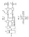
- FIG. 1shows a general block diagram of an M-ary orthogonal keying system 10 .
- input datais scrambled by a scrambler 12 as specified in the current Institute of Electrical and Electronics Engineers (IEEE) 802.11 standard.
- the datais then provided to a serial-to-parallel converter 14 which converts the serial data into 8 parallel bits forming a data symbol.
- IEEEInstitute of Electrical and Electronics Engineers
- a first modulator 16receives three (3) of the parallel bits and produces a code of length 8 chips from a look-up table
- a second modulator 18receives three (3) of the parallel bits and produces a second code of length 8 from a look-up table. Chips are actually code bits, but they are called chips to distinguish them from data bits.
- one of the parallel bitsis provided to a first exclusive-or (XOR) gate 20 which inverts the code from the first modulator if the bit has a value of one.
- the last remaining bitis provided to a second XOR gate 22 which inverts the code from the second modulator 18 if the bit has a value of one.
- the output I out of the XOR gate 20is applied to signal circuitry 21 to convert all 0's to ⁇ 1's for transmission.
- the circuitry 21can also manipulate, convert and/or process I out before being used to modulate a carrier with frequency ⁇ by mixer 24 .
- the output Q out from the XOR 22is applied to signal circuitry 23 to convert all 0's into ⁇ 1's for transmission.
- the circuitry 23can manipulate, convert and/or process Q out before being used to modulate a 90 degrees shifted carrier by mixer 26 .
- the first modulator 16corresponds to the in-phase (I) component of the output signal
- the second modulator 18corresponds to the quadrature (Q) component of the output signal.
- the modulators 16 and 18are performing M-ary orthogonal keying or encoding because each receive log 2 M bits of information and chooses one out of M orthogonal codes. By having both I and Q components with different polarities, a total of (2M) 2 possible code combinations exist, so a total of 2+2 log 2 M bits can be encoded into one orthogonal code. In this example, M is equal to 8.
- the M codes in an M-ary orthogonal keying systemare usually based on M chip Walsh codes. Using the M chip Walsh codes in an M-ary orthogonal keying system is advantageous because the M chip Walsh codes are orthogonal, which means they exhibit zero cross-correlation, so the M chip Walsh codes tend to be easily distinguishable from each other. However, using Walsh codes as the orthogonal codes can create potential problems. For example, when Walsh code 0 (all 1's) is selected as the code symbol, Walsh code 0 may appear as an unmodulated continuous wave (CW) carrier signal.
- CWcontinuous wave
- the present inventioninvolves a digital (de)modulation system which provides enhanced multipath performance by using modified orthogonal codes with reduced autocorrelation sidelobes while maintaining the cross-correlation properties of the modified codes.
- the modified orthogonal codeshave autocorrelation sidelobes that do not exceed one-half the length of the modified orthogonal code.
- an M-ary orthogonal keying (MOK) systemis used which modifies orthogonal Walsh codes using a complementary code to improve the auto-correlation properties of the Walsh codes, thereby enhancing the multipath performance of the MOK system while maintaining the orthogonality and low cross-correlation characteristics of the Walsh codes.
- FIG. 1shows a block diagram of a M-ary orthogonal keying (MOK) system using Walsh codes modified by a cover sequence (11111100);
- MOKM-ary orthogonal keying
- FIG. 2shows a block diagram of a digital modulation system using modified orthogonal codes to reduce the autocorrelation sidelobes of the orthogonal codes
- FIG. 3shows a block diagram of an embodiment of a MOK system according to the principles of the present invention
- FIG. 4shows a graphical comparison of packet error ratio versus delay spread for a MOK system using Walsh codes modified by a cover sequence in current systems v. modified Walsh codes to reduce the autocorrelation sidelobes;
- FIG. 5shows a block diagram of another embodiment of the MOK system according to the principles of the present invention.
- FIG. 6shows a graphical comparison of packet error ratio versus delay spread for embodiments of the MOK system using Walsh codes modified by a cover sequence in current systems v. modified Walsh codes to reduce the autocorrelation sidelobes;
- FIG. 7shows a block diagram of another embodiment of the MOK system according to certain principles of the present invention.
- FIG. 8shows a digital demodulator according to certain principles of the present invention
- FIG. 9shows a demodulation system using the digital demodulator according to certain principles of the present invention.
- FIG. 10shows another embodiment of a demodulation system using the digital demodulator according to the principles of the present invention.
- FIG. 2shows a digital modulator 28 according to the principles of the present invention.
- the modulator 28chooses a corresponding one of M codes.
- the M codesare produced by modifying a set of orthogonal codes to reduce the autocorrelation levels associated with those orthogonal codes while maintaining the orthogonality of the set. For example, if the same chip(s) in the codes of the orthogonal code set is inverted, the modified orthogonal codes remain orthogonal.
- an orthogonal code setis modified with another code to produce M orthogonal N-chip codes having autocorrelation sidelobes which do not exceed N/2 in value.
- the modulator 28can perform the modification of the orthogonal codes using some processing circuitry implementing some logic to perform the modification, or the modulator 28 can store the modified orthogonal codes in a look-up table.
- the modulator 28can also store different sets of modified orthogonal codes depending on desired changes in operation or calculate different sets of the modified orthogonal codes.
- the modification of the orthogonal codescan be performed by an element by element multiplication of the orthogonal codes with a code having good autocorrelation properties.
- the modulator 28produces codes with low autocorrelation properties while maintaining at least some of the orthogonality characteristics of the original orthogonal codes.
- the data bitsare shown as being received in parallel, and the code chips are shown as being produced serially.
- the data bitscan be received serially, and/or the code chips can be produced in parallel.
- Complementary codes or sequencesare sets of sequences characterized by the property that for shifts in the sequences the autocorrelations of the sequences sum to zero except for the main peak at zero shift.
- complementary codescan be used to modify the set(s) of orthogonal codes of the modulator 28 .
- Complementary codesare discussed in Robert L. Frank, “Polyphase Complementary Codes.” IEEE Transactions On Information Theory, Vol. IT-26, No. 6, November 1980, pp. 641–647.
- complementary sequencesare:
- Complementary codeshave low auto-correlation sidelobes, and a complementary code multiplied by a Walsh function produces another complementary code. As such, if a complementary code is used to modify a Walsh code set, the resulting modified Walsh codes are complementary and have the same low auto-correlation sidelobes.
- the modified Walsh code setalso remains orthogonal, which means that the cross correlation between any two different codes is zero (for a zero delay).
- FIG. 3shows an embodiment of a MOK system 30 using modulators 32 and 34 to produce length 8 codes in response to 3 information bits from the serial to parallel converter 14 .
- the set of orthogonal codesis the length 8 Walsh code set, and the Walsh code set is modified using a complementary code.
- the length 8 Walsh code setis:
- the Walsh codesare modified by an element by element exclusive-or with the code ⁇ 11111100 ⁇ , so the last two chips of each Walsh code (or the chips of the last two columns of the Walsh code set) are inverted.
- This modifying codehowever, has auto-correlation sidelobes with a worst-case magnitude of 5 (using ⁇ 1's for the 0's), which is an autocorrelation value greater than one-half the length of the 8 chip code and produces multipath performance problems.
- the MOK system 30uses (a) length 8 complementary code(s), for example the sequences ⁇ 11101101 ⁇ or ⁇ 1110101 1 ⁇ , to modify the length 8 Walsh code set.
- length 8 complementary code(s)for example the sequences ⁇ 11101101 ⁇ or ⁇ 1110101 1 ⁇
- the modified Walsh code setappears as:
- This modified Walsh code setproduces worst-case autocorrelation sidelobes having a magnitude or value of only 2. As such, this modified code compares favorably in performance to complementary Barker codes which have autocorrelation sidelobes bounded to only one.
- Complementary Barker codesare discussed in Robert L. Frank, “Polyphase Complementary Codes.” IEEE Transactions On Information Theory, Vol. IT-26, No. 6, November 1980, pp. 641–647. However, Barker codes or sequences only exist for certain odd lengths such as length 11. The first of the two complementary codes specifically mentioned above has improved cross-correlation properties for time shifted codes.
- the scrambler 12receives data and scrambles the data according to the IEEE 802.11 standard.
- the scrambler 12may not be necessary, and the data can be manipulated by some other form of data conversion, interleaving or modification, or the data can be fed directly into the serial-to-parallel converter 14 .
- the serial-to-parallel converter 14is a 1:8 multiplexer (MUX) which produces a data symbol of 8 data bits in parallel according to a 1.375 MHz clock signal.
- the eight bit data symbolis encoded into a symbol comprising a I/Q code pair of 8 codes or codewords, so the symbol interval is equal to the code length.
- the first modulator 32Three (3) of the bits of the data symbol are provided to the first modulator 32 which produces a corresponding length 8 Walsh code which has been modified by a complementary code.
- the first modulator 32produces the length 8 Walsh code at a chip rate of about 11 MHz as dictated by an 11 MHz clock signal.
- each symbolcontains 8 data bits, which are encoded into independent I and Q codes of 8 chips. Chips are actually code bits, but they are called chips to distinguish them from data bits.
- the first modulator 32corresponds to the I phase modulation branch of the MOK system 30 which produces the I component of the of the signal to be transmitted.
- a second set of three (3) bits of the data symbol from the converter 14is provided to the second modulator 34 which produces a corresponding length 8 Walsh code which has been modified using a complementary code.
- the second modulator 34corresponds to the Q phase modulation branch of the MOK system 30 which produces the Q component of the of the signal to be transmitted.
- the second modulator 34also produces a length 8 Walsh code at a chip rate of about 11 MHz as dictated by the 11 MHz clock signal.
- first XOR gate 36Of the remaining two of eight bits of the data symbol from the serial to parallel converter 14 , one is provided to a first XOR gate 36 . If the bit is a 0, the first XOR gate 36 changes the polarity of the length 8 Walsh code from the first modulator 32 . The resulting modified Walsh code I out is provided to signal circuitry 21 to change any 0's to 1's and perform any additional signal processing and/or conversion before being provided to the first mixer 24 to modulate a carrier of frequency ⁇ . The last remaining bit is provided to a second XOR gate 38 . If the bit is a 0, the second XOR gate 38 changes the polarity of the length 8 Walsh code from the second modulator 34 .
- the resulting modified Walsh code Q outis provided to the signal circuitry 23 for any conversion and/or processing before being provided to the second mixer 26 to modulate a 90 degree shifted version of the carrier with frequency ⁇ . If instead of 0's, ⁇ 1's are used, the first and second XOR gates 36 and 38 , can be replaced by multipliers to change the polarity of I out and Q out . Subsequently, the I out modulated carrier and the Q out modulated carrier are combined and transmitted. As such, this particular embodiment of the MOK system 30 partitions 8 bits of incoming data into 4 bits for the I branch and 4 bits for the Q branch.
- the three data bits on the I branchare encoded into a code of 8 chips, and the three data bits on the Q branch are encoded in parallel into a code of 8 chips. Because the last two bits encode information by determining the polarity of the 8 bit symbols respectively, the MOK system 30 encodes 8 data bits into 2 codes which are both picked from a set of 16 possible codes. In this example, there are 8 modified Walsh codes, which can be inverted to get 16 codes. With a symbol rate of 1.375 MSps and 8 bits/symbol, the data rate for the MOK system 30 is 11 MBps.
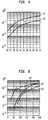
- FIG. 4shows a graphical comparison of the packet error ratio v. delay spread (ns) in multipath fading channels using 8 bits per symbol at 11 Mbps and a 4 taps channel matched filter as would be understood by one of ordinary skill in the art.
- Curve 40corresponds to digital modulation using Walsh codes modified by the cover sequence (11111100) of systems of the current art
- curve 42corresponds to digital modulation using Walsh codes modified by a complementary code (11101011) according to the principles of the present invention.
- the channel model usedhas an exponentially decaying power delay profile and independent Rayleigh fading paths.
- FIG. 4shows that by using the complementary code, the system can tolerate a delay spread that is about 50% larger (curve 42 ) than for the other code (curve 40 ) to achieve a packet error ratio of 1% or 10%.
- FIG. 5shows an embodiment of a MOK system 50 which can be used as a fallback mode for the MOK system 30 ( FIG. 3 ).
- the input datais scrambled by the scrambler 12 according to the IEEE 802.11 standard.
- the datais provided to a serial to parallel converter 52 .
- the serial to parallel converter 52in this embodiment produces 5 bit data symbols in parallel at a data symbol rate of 1.375 MSps.
- From the 5 bit data symbolthree bits are received by a modulator 54 which encodes the 3 bits into a length 8 modified Walsh code according to the principles of the present invention.
- the length 8 modified Walsh codeis provided to both I and Q branches 56 and 58 .
- this embodimentallows a fallback mode with independent phase modulation, such as quadrature phase shift keying (QPSK) or 8-phase shift keying (8-PSK), of the same code on the multiple phase modulation paths, such as the I and Q branches 56 and 58 in this embodiment.
- QPSKquadrature phase shift keying
- 8-PSK8-phase shift keying
- the 8 chip modified Walsh codeis serially provided to a first XOR gate 60
- the 8 chip Walsh codeis serially provided to a second XOR gate 62 .
- one bitgoes to the first XOR gate 60 to adjust the polarity of the length 8 modified Walsh code and produce I out on the I branch 56
- the other bitgoes to the second XOR gate 62 to adjust the polarity of the length 8 modified Walsh code and produce Q out on the Q branch 58 .
- the first and second XOR gates 60 and 62can be replaced by multipliers. As such, given data symbols of 5 bits/symbol and a symbol rate of 1.375 MBps, this embodiment provides a data rate of 6.8 MBps.
- FIG. 6shows a graphical comparison of the packet error ratio v. delay spread (ns) in multipath fading channels using 1) Walsh codes modified by the cover sequence (11111100) of current systems with quadrature phase shift keying (QPSK) at a fallback rate of 6.8 Mbps (curve 63 ), 2) Walsh codes modified by a complementary code (for example, 11101011) using 8-phase shift keying (8-PSK) at 8.25 Mbps (curve 64 ), and 3) Walsh codes modified by a complementary code (for example, 11101011) using QPSK at a fallback rate of 6.8 Mbps and the same code on I and Q branches (curve 65 ).
- the channel model usedhas an exponentially decaying power delay profile and independent Rayleigh fading paths.
- FIG. 6shows that the delay spread tolerance is more than doubled by using the codes proposed by the invention. Additionally, FIG. 6 shows that the digital modulation system can be used with alternative modulation schemes, such as 8-PSK instead of QPSK, to get a higher data rate (8.25 Mbps) without losing much delay spread performance as would be understood by one of skill in the art.
- 8-PSKinstead of QPSK
- FIG. 7shows an embodiment of a MOK system 66 which can be used as a fallback mode for the MOK system 30 ( FIG. 3 ).
- the input datais scrambled by the scrambler 12 according to the IEEE 802.11 standard.
- the scrambled datais provided to a serial to parallel converter 68 .
- the serial to parallel converter 68in this embodiment produces 4 bit data symbols in parallel at a symbol rate of 1.375 MSps. From the 4 bit data symbol, three bits are received by a modulator 70 which encodes the 3 bits into a length 8 modified Walsh code according to the principles of the present invention.
- the modulator 70serially produces the length 8 Walsh code at a rate of 11 MHz.
- the length 8 modified Walsh codeis provided to an XOR gate 72 corresponding to both the I and Q branches.
- the length 8 modified Walsh codeis multiplied by the remaining bit of the data symbol from the serial-to-parallel converter 68 to adjust the polarity of the length 8 code and produce I out and Q out in serial form.
- the XOR gate 72can be replaced by a multiplier. As such, given data symbols of 4 bits/symbol and a symbol rate of 1.375 MBps, this embodiment provides a data rate of 5.5 MBps.
- FIG. 8shows a digital demodulation system 76 which can be used at a receiver (not shown) to receive transmitted codes from a transmitter (not shown) using an embodiment of the digital modulation system described above.
- the digital demodulation system 76receives a modified orthogonal code according to the principles of the present invention. In response to the modified orthogonal code, the digital demodulation system produces a corresponding data symbol.
- the code chips and/or the data bitscan be in parallel or in series.
- FIG. 9shows a demodulation system 80 using the digital demodulation system according to the principles of the present invention.
- the received signalis supplied to both I and Q branches 82 and 84 of the demodulation system 80 .
- a first mixer 86multiplies the received signal by the cos ⁇ t, where ⁇ is the carrier frequency, to extract the modulated I information
- a second mixer 88multiplies the received signal by sin ⁇ t to extract the modulated Q information.
- the I and Q informationare provided to correlator blocks 90 and 92 , respectively.
- the correlator blocks 90 and 92contain 8 correlators for correlating time delayed versions of the I information and the Q information, respectively.
- the find code blocks 94 and 96find the known modified orthogonal codes according to the present invention which give the highest correlation magnitudes for the I and Q information.
- the demodulator 76FIG. 8 or portions thereof can be performed in or receive the output from the find code blocks 94 and 96 to decode the known orthogonal codes into corresponding data bits.
- the digital demodulation system 76FIG. 8 or portions thereof can be implemented in the find code blocks 94 and 96 , in the detect polarity blocks 98 and 100 , branching off of the of the I and Q paths 82 and 84 and/or at the output of detect polarity blocks 98 and 100 to decode the modified orthogonal codes to produce the corresponding data bits.
- the detect polarity blocks 98 and 100each decodes an additional data bit each from the polarity of the found modified orthogonal code.
- FIG. 10shows an embodiment of a demodulation system 110 which can be used at the fallback rate for the demodulator system 80 ( FIG. 9 ) receiving code symbols from the modulator system 50 ( FIG. 5 ) where the same code is transmitted on multiple modulation paths.
- the difference between the demodulation system 110 and the full rate demodulation system of FIG. 9is that the code detection block 112 adds the squared correlation outputs of the I and Q correlators 90 and 92 and detects the modified orthogonal code according to the present invention which gave the highest correlation complex magnitude.
- the same codeis on both the I and Q paths 82 and 84 for digital demodulation.
- a block 114finds the modified orthogonal code with the highest complex correlation magnitude.
- the demodulator 76 or portions thereofcan be performed in or receive the output from the find code block 112 to decode the modified orthogonal codes into corresponding data bits.
- the digital demodulation system 76 ( FIG. 8 ) or portions thereofcan be implemented in the code detection block 112 , in a phase detector 114 , branching off of the path 116 and/or at the output of the phase detector 114 to decode the modified orthogonal codes and produce the corresponding data bits.
- the phase detector 114detects the phase of the complex correlation output to decode an extra 2 bits per code symbol for QPSK or an extra 3 bits per code symbol for 8-PSK.
- the digital modulation systemhas been described as using orthogonal codes of 1's and 0's which are modified by codes of 1's and 0's, but the digital modulation system can be performed using codes of 1's and ⁇ 1's or 1's and 0's depending on the embodiment.
- codes of 1's and ⁇ 1'sare received at the receiver, and the correlation determinations are described in terms of 1's and ⁇ 1's , but the demodulation system can use 1's and 0's or 1's and ⁇ 1's depending on the embodiment.
- the digital modulation systemhas been described using a particular configuration of distinct components, but the digital modulation system can be performed in different configurations and in conjunction with other processes. Additionally, the various components making up the digital modulation system and their respective operating parameters and characteristics should be properly matched up with the operating environment to provide proper operation. It should also be understood that the digital modulation system and portions thereof can be implemented in application specific integrated circuits, software-driven processing circuitry, firmware, lookup-tables or other arrangements of discrete components as would be understood by one of ordinary skill in the art with the benefit of this disclosure. What has been described is merely illustrative of the application of the principles of the present invention. Those skilled in the art will readily recognize that these and various other modifications, arrangements and methods can be made to the present invention without strictly following the exemplary applications illustrated and described herein and without departing from the spirit and scope of the present invention.
Landscapes
- Engineering & Computer Science (AREA)
- Computer Networks & Wireless Communication (AREA)
- Signal Processing (AREA)
- Theoretical Computer Science (AREA)
- Digital Transmission Methods That Use Modulated Carrier Waves (AREA)
Abstract
Description
| 1 | 1 | 1 | −1 | |||
| shifted | 1 | 1 | 1 | −1 | ||
| 1 | 1 | 1 | 1 | |||
| correlation = sum of multiplied values = 4. | ||
For a shift of one chip, the autocorrelation is:
| 1 | 1 | 1 | −1 | ||||
| shifted | 1 | 1 | 1 | −1 | |||
| 1 | 1 | −1 | |||||
| correlation = sum of multiplied values = 1. | ||
For a shift of 2 chips, the autocorrelation is:
| 1 | 1 | 1 | −1 | |||||
| shifted | 1 | 1 | 1 | −1 | ||||
| 1 | −1 | |||||||
| correlation = sum of multiplied values = 0. | ||
For a shift of 3 chips, the autocorrelation is:
| 1 | 1 | 1 | −1 | ||||||
| shifted | 1 | 1 | 1 | −1 | |||||
| multiplication | −1 | ||||||||
| correlation = sum of multiplied values = −1. | ||
Larger shifts give an autocorrelation value of zero, so the maximum autocorrelation sidelobe in this example has a value or magnitude of 1. In this example, −1's are used in the receiver instead of 0's. The autocorrelation sidelobes give an indication about multipath performance. If the autocorrelation sidelobes are large, several multipath components heavily interfere with each other.
| 1 | 1 | 1 | 1 | 1 | 1 | 1 | 1 | ||
| 1 | 1 | 1 | 1 | 0 | 0 | 0 | 0 | ||
| 1 | 1 | 0 | 0 | 1 | 1 | 0 | 0 | ||
| 1 | 0 | 0 | 1 | 1 | 0 | 0 | 1 | ||
| 1 | 0 | 1 | 0 | 1 | 0 | 1 | 0 | ||
| 1 | 0 | 1 | 0 | 0 | 1 | 0 | 1 | ||
| 1 | 0 | 0 | 1 | 0 | 1 | 1 | 0 | ||
| 1 | 1 | 0 | 0 | 0 | 0 | 1 | 1 | ||
In previous systems, the Walsh codes are modified by an element by element exclusive-or with the code {11111100}, so the last two chips of each Walsh code (or the chips of the last two columns of the Walsh code set) are inverted. This modifying code, however, has auto-correlation sidelobes with a worst-case magnitude of 5 (using −1's for the 0's), which is an autocorrelation value greater than one-half the length of the 8 chip code and produces multipath performance problems.
| 1 | 1 | 1 | 0 | 1 | 0 | 1 | 1 | ||
| 1 | 1 | 1 | 0 | 0 | 1 | 0 | 0 | ||
| 1 | 1 | 0 | 1 | 1 | 0 | 0 | 0 | ||
| 1 | 0 | 0 | 0 | 1 | 1 | 0 | 1 | ||
| 1 | 0 | 1 | 1 | 1 | 1 | 1 | 0 | ||
| 1 | 0 | 1 | 1 | 0 | 0 | 0 | 1 | ||
| 1 | 0 | 0 | 0 | 0 | 0 | 1 | 0 | ||
| 1 | 1 | 0 | 1 | 0 | 1 | 1 | 1 | ||
This modified Walsh code set produces worst-case autocorrelation sidelobes having a magnitude or value of only 2. As such, this modified code compares favorably in performance to complementary Barker codes which have autocorrelation sidelobes bounded to only one. Complementary Barker codes are discussed in Robert L. Frank, “Polyphase Complementary Codes.” IEEE Transactions On Information Theory, Vol. IT-26, No. 6, November 1980, pp. 641–647. However, Barker codes or sequences only exist for certain odd lengths such as
Claims (64)
Priority Applications (5)
| Application Number | Priority Date | Filing Date | Title |
|---|---|---|---|
| US10/153,412US7787355B2 (en) | 1998-04-08 | 2002-05-22 | M-ary orthogonal keying system |
| US11/484,443US7583582B2 (en) | 1996-07-30 | 2006-07-10 | M-ary orthogonal keying system |
| US11/981,880US7778146B2 (en) | 1996-07-30 | 2007-10-31 | M-ary orthogonal keying system |
| US12/508,785US7957256B2 (en) | 1996-07-30 | 2009-07-24 | M-ary orthogonal keying system |
| US13/080,018US8514690B2 (en) | 1996-07-30 | 2011-04-05 | M-ary orthogonal keying system |
Applications Claiming Priority (2)
| Application Number | Priority Date | Filing Date | Title |
|---|---|---|---|
| US09/057,310US6404732B1 (en) | 1996-07-30 | 1998-04-08 | Digital modulation system using modified orthogonal codes to reduce autocorrelation |
| US10/153,412US7787355B2 (en) | 1998-04-08 | 2002-05-22 | M-ary orthogonal keying system |
Related Parent Applications (1)
| Application Number | Title | Priority Date | Filing Date |
|---|---|---|---|
| US09/057,310ContinuationUS6404732B1 (en) | 1996-07-30 | 1998-04-08 | Digital modulation system using modified orthogonal codes to reduce autocorrelation |
Related Child Applications (2)
| Application Number | Title | Priority Date | Filing Date |
|---|---|---|---|
| US11/484,443ContinuationUS7583582B2 (en) | 1996-07-30 | 2006-07-10 | M-ary orthogonal keying system |
| US11/981,880ContinuationUS7778146B2 (en) | 1996-07-30 | 2007-10-31 | M-ary orthogonal keying system |
Publications (2)
| Publication Number | Publication Date |
|---|---|
| US20020186651A1 US20020186651A1 (en) | 2002-12-12 |
| US7787355B2true US7787355B2 (en) | 2010-08-31 |
Family
ID=22009820
Family Applications (2)
| Application Number | Title | Priority Date | Filing Date |
|---|---|---|---|
| US09/057,310Expired - LifetimeUS6404732B1 (en) | 1996-07-30 | 1998-04-08 | Digital modulation system using modified orthogonal codes to reduce autocorrelation |
| US10/153,412Expired - Fee RelatedUS7787355B2 (en) | 1996-07-30 | 2002-05-22 | M-ary orthogonal keying system |
Family Applications Before (1)
| Application Number | Title | Priority Date | Filing Date |
|---|---|---|---|
| US09/057,310Expired - LifetimeUS6404732B1 (en) | 1996-07-30 | 1998-04-08 | Digital modulation system using modified orthogonal codes to reduce autocorrelation |
Country Status (7)
| Country | Link |
|---|---|
| US (2) | US6404732B1 (en) |
| EP (2) | EP0949765A3 (en) |
| JP (3) | JPH11331041A (en) |
| KR (1) | KR19990083039A (en) |
| AU (1) | AU2359199A (en) |
| BR (1) | BR9901243A (en) |
| CA (1) | CA2261824C (en) |
Cited By (2)
| Publication number | Priority date | Publication date | Assignee | Title |
|---|---|---|---|---|
| US20100260274A1 (en)* | 2009-04-09 | 2010-10-14 | Seiko Epson Corporation | Communication method and communication system |
| US20110182170A1 (en)* | 1996-07-30 | 2011-07-28 | Nee D J Richard Van | Digital Modulation System Using Modified Orthogonal Codes To Reduce Autocorrelation |
Families Citing this family (39)
| Publication number | Priority date | Publication date | Assignee | Title |
|---|---|---|---|---|
| US6404732B1 (en)* | 1996-07-30 | 2002-06-11 | Agere Systems Guardian Corp. | Digital modulation system using modified orthogonal codes to reduce autocorrelation |
| US5982807A (en)* | 1997-03-17 | 1999-11-09 | Harris Corporation | High data rate spread spectrum transceiver and associated methods |
| US6426978B1 (en) | 1998-10-01 | 2002-07-30 | Ericsson Inc. | Digital communication systems and methods for differential and/or amplitude encoding and decoding secondary symbols |
| KR100294711B1 (en)* | 1999-03-15 | 2001-07-12 | 서평원 | Frame Synchronization Method using Optimal Pilot Symbol |
| US7643540B2 (en)* | 1999-03-15 | 2010-01-05 | Lg Electronics Inc. | Pilot signals for synchronization and/or channel estimation |
| US7496132B2 (en)* | 1999-03-15 | 2009-02-24 | Kg Electronics Inc. | Pilot signals for synchronization and/or channel estimation |
| US7039036B1 (en)* | 1999-04-01 | 2006-05-02 | Texas Instruments Incorporated | Reduced complexity primary and secondary synchronization codes with good correlation properties for WCDMA |
| FR2795894B1 (en)* | 1999-06-29 | 2001-10-05 | Commissariat Energie Atomique | MULTI-MAK MODULATION/DEMODULATION TRANSMISSION METHOD, CORRESPONDING TRANSMITTER AND RECEIVER |
| US6885691B1 (en)* | 1999-08-02 | 2005-04-26 | Lg Information & Communications, Ltd. | Scrambling codes and channelization codes for multiple chip rate signals in CDMA cellular mobile radio communication system |
| US6987752B1 (en)* | 1999-09-15 | 2006-01-17 | Lucent Technologies Inc. | Method and apparatus for frequency offset estimation and interleaver synchronization using periodic signature sequences |
| FR2803467B1 (en) | 1999-12-30 | 2002-02-08 | Mitsubishi Electric Inf Tech | METHOD OF ESTIMATING A TRANSMISSION OR TELECOMMUNICATION CHANNEL |
| US6845104B2 (en)* | 2000-06-14 | 2005-01-18 | Ipr Licensing, Inc. | Receiver for time division multiplex system without explicit time slot assignment |
| FR2813474B1 (en)* | 2000-08-28 | 2002-12-13 | Commissariat Energie Atomique | NON-CONSISTENT DP-MOK RECEPTION METHOD WITH MULTIPLE PATH COMBINATION AND CORRESPONDING RECEIVER |
| DE60036949T2 (en) | 2000-11-20 | 2008-02-07 | Lucent Technologies Inc. | Method and apparatus for detecting phase modulated CCK symbols with a correlator bank |
| CN1146171C (en)* | 2000-11-24 | 2004-04-14 | 华为技术有限公司 | Realization Method of Large Capacity Synchronous Code Division Multiple Access Spread Spectrum Communication System |
| US20020122468A1 (en)* | 2001-01-12 | 2002-09-05 | Terion, Inc. | Quasi orthogonal hybrid walsh-PN codes for CDMA application in HF modems |
| RU2188516C1 (en)* | 2001-05-21 | 2002-08-27 | Военный университет связи | Quaternary-coded radio signal transmission system |
| US7389537B1 (en) | 2001-10-09 | 2008-06-17 | Juniper Networks, Inc. | Rate limiting data traffic in a network |
| AU2003211106A1 (en)* | 2002-02-20 | 2003-09-09 | Xtremespectrum, Inc. | M-ary orthagonal coded communications method and system |
| FR2845842B1 (en)* | 2002-10-09 | 2005-01-14 | Canon Kk | OPTIMIZED TRANSMISSION AND RECEPTION METHODS AND DEVICES |
| ES2255390B1 (en)* | 2004-05-28 | 2008-02-01 | Vicente Diaz Fuente | DEVICE AND METHOD OF OPTIMAL ESTIMATION OF THE DISTORTION OF THE TRANSMISSION MEDIA THROUGH THE SEQUENTIAL ISSUANCE OF PAIRS OF COMPLEMENTARY SEQUENCES IN QUADRATURE. |
| RU2258313C1 (en)* | 2004-06-15 | 2005-08-10 | Государственное образовательное учреждение высшего профессионального образования "Ульяновский государственный технический университет" | System for transmitting quadruple-encoded radio signals |
| JP2008524112A (en)* | 2004-12-20 | 2008-07-10 | コーニング インコーポレイテッド | How to make a glass envelope |
| US7826472B2 (en)* | 2005-02-18 | 2010-11-02 | Avaya Inc. | Methods and systems for providing priority access to 802.11 endpoints using DCF protocol |
| US7587660B2 (en)* | 2005-04-22 | 2009-09-08 | Kansas State University Research Foundation | Multiple-access code generation |
| US8910027B2 (en)* | 2005-11-16 | 2014-12-09 | Qualcomm Incorporated | Golay-code generation |
| US8429502B2 (en)* | 2005-11-16 | 2013-04-23 | Qualcomm Incorporated | Frame format for millimeter-wave systems |
| US8583995B2 (en)* | 2005-11-16 | 2013-11-12 | Qualcomm Incorporated | Multi-mode processor |
| US8418040B2 (en)* | 2005-11-16 | 2013-04-09 | Qualcomm Incorporated | Method and apparatus for single carrier and OFDM sub-block transmission |
| RU2315428C9 (en)* | 2006-06-23 | 2008-04-27 | Федеральный научно-производственный центр Открытое акционерное общество "Научно-производственное объединение "Марс" | System for transmitting data with multi access and time division of channels |
| US8472497B2 (en)* | 2007-10-10 | 2013-06-25 | Qualcomm Incorporated | Millimeter wave beaconing with directional antennas |
| US8503547B2 (en)* | 2007-10-11 | 2013-08-06 | Qualcomm Incorporated | Scrambling codes for secondary synchronization codes in wireless communication systems |
| JP5474823B2 (en)* | 2007-12-28 | 2014-04-16 | コーニンクレッカ フィリップス エヌ ヴェ | System and method for multi-resolution packet communication for ultra-low power wireless networks |
| US20110182169A1 (en)* | 2009-09-13 | 2011-07-28 | Research Institute Of Tsinghua University In Shenzhen | Code division multiplexing method and system |
| US8400995B2 (en)* | 2010-09-22 | 2013-03-19 | Freescale Semiconductor, Inc. | System and method for descrambling data |
| US9240853B2 (en) | 2012-11-16 | 2016-01-19 | Huawei Technologies Co., Ltd. | Systems and methods for sparse code multiple access |
| JP6255248B2 (en)* | 2014-01-14 | 2017-12-27 | パナソニック株式会社 | Multi-sector radar |
| RU2740001C1 (en)* | 2020-03-05 | 2020-12-30 | федеральное государственное казенное военное образовательное учреждение высшего образования Военная академия связи имени Маршала Советского Союза С.М. Буденного" Министерства обороны Российской Федерации | Device for transmission of four-coded radio signals |
| CN112350716B (en)* | 2020-11-27 | 2023-08-04 | 中科南京智能技术研究院 | Complement operation method and device and operation method of complement operation device |
Citations (15)
| Publication number | Priority date | Publication date | Assignee | Title |
|---|---|---|---|---|
| US4514853A (en) | 1982-12-13 | 1985-04-30 | The United States Of America As Represented By The Secretary Of The Army | Multiplexed noise code generator utilizing transposed codes |
| US5309474A (en) | 1990-06-25 | 1994-05-03 | Qualcomm Incorporated | System and method for generating signal waveforms in a CDMA cellular telephone system |
| US5325394A (en)* | 1992-06-29 | 1994-06-28 | Motorola, Inc. | Method and apparatus for canceling spread-spectrum noise |
| US5533013A (en)* | 1992-12-01 | 1996-07-02 | Nokia Mobile Phones Limited | Communication method and system |
| WO1996024198A1 (en) | 1995-02-01 | 1996-08-08 | Hitachi, Ltd. | Spectrum spreading communication device and communication system |
| US5602833A (en)* | 1994-12-19 | 1997-02-11 | Qualcomm Incorporated | Method and apparatus for using Walsh shift keying in a spread spectrum communication system |
| EP0828365A2 (en) | 1996-09-04 | 1998-03-11 | Lucent Technologies Inc. | Multicarrier modulation using complementarycodes and amplitude modulation |
| US5751761A (en)* | 1993-07-20 | 1998-05-12 | Qualcomm Incorporated | System and method for orthogonal spread spectrum sequence generation in variable data rate systems |
| DE19646299A1 (en) | 1996-11-11 | 1998-05-14 | Bosch Gmbh Robert | Method for decoding complementary codes |
| US5809060A (en) | 1994-02-17 | 1998-09-15 | Micrilor, Inc. | High-data-rate wireless local-area network |
| US5848060A (en)* | 1994-01-11 | 1998-12-08 | Ericsson Inc. | Cellular/satellite communications system with improved frequency re-use |
| US6108317A (en)* | 1995-11-01 | 2000-08-22 | Stm Wireless, Inc. | Cyclic code phase multiple access for inbound satellite communications |
| US6404732B1 (en)* | 1996-07-30 | 2002-06-11 | Agere Systems Guardian Corp. | Digital modulation system using modified orthogonal codes to reduce autocorrelation |
| US6452958B1 (en)* | 1996-07-30 | 2002-09-17 | Agere Systems Guardian Corp | Digital modulation system using extended code set |
| US7583582B2 (en)* | 1996-07-30 | 2009-09-01 | Agere Systems Inc. | M-ary orthogonal keying system |
Family Cites Families (19)
| Publication number | Priority date | Publication date | Assignee | Title |
|---|---|---|---|---|
| US4176316A (en) | 1953-03-30 | 1979-11-27 | International Telephone & Telegraph Corp. | Secure single sideband communication system using modulated noise subcarrier |
| FR2461411B1 (en)* | 1979-07-13 | 1985-10-31 | Trt Telecom Radio Electr | DATA TRANSMISSION SYSTEM USING SPECTRUM SPREADING PRINCIPLES |
| US4513288A (en)* | 1982-03-29 | 1985-04-23 | The United States Of America As Represented By The Secretary Of The Army | Group-complementary code sets for implementing pulse-compression processing with optimum aperiodic autocorrelation and optimum cross-correlation properties |
| US4494228A (en)* | 1982-08-12 | 1985-01-15 | The United States Of America As Represented By The Secretary Of The Army | Orthogonal code division multiple access communications systems |
| US4529633A (en) | 1983-01-14 | 1985-07-16 | Diab-Barracuda Ab | Thermal camouflage |
| US4529963A (en)* | 1983-06-22 | 1985-07-16 | Gutleber Frank S | Code expansion generator |
| US4707839A (en) | 1983-09-26 | 1987-11-17 | Harris Corporation | Spread spectrum correlator for recovering CCSK data from a PN spread MSK waveform |
| US4771425A (en)* | 1984-10-29 | 1988-09-13 | Stratacom, Inc. | Synchoronous packet voice/data communication system |
| US4901307A (en) | 1986-10-17 | 1990-02-13 | Qualcomm, Inc. | Spread spectrum multiple access communication system using satellite or terrestrial repeaters |
| US5148429A (en)* | 1988-10-27 | 1992-09-15 | Kabushiki Kaisha Toshiba | Voice data transmission system and method |
| US5109390A (en) | 1989-11-07 | 1992-04-28 | Qualcomm Incorporated | Diversity receiver in a cdma cellular telephone system |
| US5187671A (en) | 1990-08-24 | 1993-02-16 | Microelectronics And Computer Technology Corporation | Automated interconnect routing system |
| JP2823341B2 (en)* | 1990-08-29 | 1998-11-11 | 積水化学工業株式会社 | Spread spectrum communication system and apparatus |
| US5218619A (en) | 1990-12-17 | 1993-06-08 | Ericsson Ge Mobile Communications Holding, Inc. | CDMA subtractive demodulation |
| US5151919A (en) | 1990-12-17 | 1992-09-29 | Ericsson-Ge Mobile Communications Holding Inc. | Cdma subtractive demodulation |
| US5357454A (en) | 1991-07-25 | 1994-10-18 | Ericsson Ge Mobile Communications Holding, Inc. | Fast walsh transform processor |
| JPH05145515A (en) | 1991-11-19 | 1993-06-11 | Canon Inc | Spread spectrum communication equipment |
| US5353352A (en) | 1992-04-10 | 1994-10-04 | Ericsson Ge Mobile Communications Inc. | Multiple access coding for radio communications |
| JPH07170288A (en)* | 1993-12-15 | 1995-07-04 | Hitachi Ltd | Voice communication system and voice communication method |
- 1998
- 1998-04-08USUS09/057,310patent/US6404732B1/ennot_activeExpired - Lifetime
- 1999
- 1999-02-15CACA002261824Apatent/CA2261824C/ennot_activeExpired - Fee Related
- 1999-03-29EPEP99302446Apatent/EP0949765A3/ennot_activeWithdrawn
- 1999-04-06AUAU23591/99Apatent/AU2359199A/ennot_activeAbandoned
- 1999-04-07JPJP11100555Apatent/JPH11331041A/enactivePending
- 1999-04-08BRBR9901243-0Apatent/BR9901243A/ennot_activeApplication Discontinuation
- 1999-04-08KRKR1019990012278Apatent/KR19990083039A/ennot_activeWithdrawn
- 1999-04-13EPEP99302875Apatent/EP0952678A1/ennot_activeWithdrawn
- 2002
- 2002-05-22USUS10/153,412patent/US7787355B2/ennot_activeExpired - Fee Related
- 2003
- 2003-08-14JPJP2003293511Apatent/JP3905500B2/ennot_activeExpired - Lifetime
- 2006
- 2006-10-25JPJP2006289337Apatent/JP4527702B2/ennot_activeExpired - Lifetime
Patent Citations (16)
| Publication number | Priority date | Publication date | Assignee | Title |
|---|---|---|---|---|
| US4514853A (en) | 1982-12-13 | 1985-04-30 | The United States Of America As Represented By The Secretary Of The Army | Multiplexed noise code generator utilizing transposed codes |
| US5309474A (en) | 1990-06-25 | 1994-05-03 | Qualcomm Incorporated | System and method for generating signal waveforms in a CDMA cellular telephone system |
| US5325394A (en)* | 1992-06-29 | 1994-06-28 | Motorola, Inc. | Method and apparatus for canceling spread-spectrum noise |
| US5533013A (en)* | 1992-12-01 | 1996-07-02 | Nokia Mobile Phones Limited | Communication method and system |
| US5751761A (en)* | 1993-07-20 | 1998-05-12 | Qualcomm Incorporated | System and method for orthogonal spread spectrum sequence generation in variable data rate systems |
| US5848060A (en)* | 1994-01-11 | 1998-12-08 | Ericsson Inc. | Cellular/satellite communications system with improved frequency re-use |
| US5809060A (en) | 1994-02-17 | 1998-09-15 | Micrilor, Inc. | High-data-rate wireless local-area network |
| US5602833A (en)* | 1994-12-19 | 1997-02-11 | Qualcomm Incorporated | Method and apparatus for using Walsh shift keying in a spread spectrum communication system |
| WO1996024198A1 (en) | 1995-02-01 | 1996-08-08 | Hitachi, Ltd. | Spectrum spreading communication device and communication system |
| US6108317A (en)* | 1995-11-01 | 2000-08-22 | Stm Wireless, Inc. | Cyclic code phase multiple access for inbound satellite communications |
| US6404732B1 (en)* | 1996-07-30 | 2002-06-11 | Agere Systems Guardian Corp. | Digital modulation system using modified orthogonal codes to reduce autocorrelation |
| US6452958B1 (en)* | 1996-07-30 | 2002-09-17 | Agere Systems Guardian Corp | Digital modulation system using extended code set |
| US7079567B2 (en)* | 1996-07-30 | 2006-07-18 | Agere Systems, Inc. | Digital modulation system using extended code set |
| US7583582B2 (en)* | 1996-07-30 | 2009-09-01 | Agere Systems Inc. | M-ary orthogonal keying system |
| EP0828365A2 (en) | 1996-09-04 | 1998-03-11 | Lucent Technologies Inc. | Multicarrier modulation using complementarycodes and amplitude modulation |
| DE19646299A1 (en) | 1996-11-11 | 1998-05-14 | Bosch Gmbh Robert | Method for decoding complementary codes |
Non-Patent Citations (12)
| Title |
|---|
| Agere Claim Construction Brief - Agere Systems v. Intersil Corporation - Federal District Court (Delaware), Civil Action No. 02-1544-JJF Sep. 2006. |
| Aldis, J.P., et al, "Physical layer Architecture And Performance In The Wand User Trial System," ACTS Mobile Communications, Summer '96, Granada, Spain, Nov. 27-29, 1996, pp. i-x, 196-203. |
| Defendant Sony Computer Entertainment America Inc.'s Answer and Counterclaim To Plaintiffs First Amended Complaint For Patent Infringement - Agere Systems v. Sony Corporation, et al., U.S. Distric Court, Eastern District of Texas, Marshall Division, Case No. 2:06-CV-00079-TJW Nov. 2006. |
| Frank, Robert L.; "Polyphase Complementary Codes", IEEE Transactions on Information Theory, vol. IT-26, pp. 641-647, Nov. 1980.* |
| Intersil Opening Brief on Claim Construction - Agere Systems v. Intersil Corporaton - Federal District Court (Delaware), Civil Action No. 02-1544-JJF Sep. 2006. |
| van Nee, R, "Multipath Effects On GPS Code Phase Measurements" Navigation Journal Of The Institute Of Navigation, vol. 39, No. 2, Summer 1992, pp. 177-190. |
| van Nee, R, "OFDM Codes For Peak To Average Power Reduction And Error Correction," IEEE, 1996, pp. 740-744. |
| van Nee, R, "OFDM Codes For Peak-To-Average Power Reduction And Error Correction," Global Telecommunications Conference (GLOBCOM), us, New York, Nov. 1996, pp. 740-744. |
| van Nee, R, et al. "Magic In Reality, Building The Wand Modem," ACTS Mobile Communications, Summer '97, Aalborg Denmark, Oct. 7-10, 1997, pp. 533-538, 775-780. |
| van Nee, R, et al. "Performance Degradation Due To Code Tracking Errors In Spread-Spectrum Code-Division Multiple-Access Systems," IEEE Journal On Selected Areas in Communications, vol. 14, No. 8, Oct. 1996, pp. 1669-1679. |
| van Nee, R, et al. OFDM For Wireless Multimedia Communications, Chapter 10: "Applications of OFDM," pp. 229-241, Artech House, 2000. |
| Wilkinson, T, et al, "Minimisation Of The Peak To Mean Envelope Power Ratio Of Multicarrier Transmission Schemes By Block Coding," Proceedings Of The Vehicular Technology Conference, US, New York, Jul. 1995, pp. 825-829. |
Cited By (4)
| Publication number | Priority date | Publication date | Assignee | Title |
|---|---|---|---|---|
| US20110182170A1 (en)* | 1996-07-30 | 2011-07-28 | Nee D J Richard Van | Digital Modulation System Using Modified Orthogonal Codes To Reduce Autocorrelation |
| US8514690B2 (en) | 1996-07-30 | 2013-08-20 | Lsi Corporation | M-ary orthogonal keying system |
| US20100260274A1 (en)* | 2009-04-09 | 2010-10-14 | Seiko Epson Corporation | Communication method and communication system |
| US8363751B2 (en)* | 2009-04-09 | 2013-01-29 | Seiko Epson Corporation | Communication method and communication system |
Also Published As
| Publication number | Publication date |
|---|---|
| US20020186651A1 (en) | 2002-12-12 |
| JP2007049749A (en) | 2007-02-22 |
| US6404732B1 (en) | 2002-06-11 |
| AU2359199A (en) | 1999-10-21 |
| JP3905500B2 (en) | 2007-04-18 |
| JP4527702B2 (en) | 2010-08-18 |
| CA2261824A1 (en) | 1999-10-08 |
| BR9901243A (en) | 2000-01-18 |
| JP2004015828A (en) | 2004-01-15 |
| EP0949765A3 (en) | 1999-10-27 |
| CA2261824C (en) | 2005-05-10 |
| JPH11331041A (en) | 1999-11-30 |
| EP0949765A2 (en) | 1999-10-13 |
| KR19990083039A (en) | 1999-11-25 |
| EP0952678A1 (en) | 1999-10-27 |
Similar Documents
| Publication | Publication Date | Title |
|---|---|---|
| US7787355B2 (en) | M-ary orthogonal keying system | |
| US7583582B2 (en) | M-ary orthogonal keying system | |
| US7079567B2 (en) | Digital modulation system using extended code set | |
| CA2292627C (en) | Wireless communications system for transmitting and receiving data with increased data rates and robustness | |
| JP3406319B2 (en) | High-speed data transmission wireless local area network | |
| US5237586A (en) | Rake receiver with selective ray combining | |
| EP1311095B1 (en) | Method for spread-spectrum digital communication by golay complementary sequence modulation | |
| KR100343089B1 (en) | A method and apparatus for facilitating multi-rate data transmission by selecting a plurality of spreading codes | |
| EP1118193B1 (en) | Encoding/decoding additional symbols in a communications system | |
| US6674790B1 (en) | System and method employing concatenated spreading sequences to provide data modulated spread signals having increased data rates with extended multi-path delay spread | |
| USRE41931E1 (en) | Receiver module and receiver formed from several cascaded modules | |
| JP4272593B2 (en) | Digital modulation system using orthogonal code modified to reduce autocorrelation | |
| JP3475242B2 (en) | Receiving device, receiving method, program, and information recording medium | |
| WO2012037638A1 (en) | A tri-phase code generator in a cdma wireless communication system |
Legal Events
| Date | Code | Title | Description |
|---|---|---|---|
| STCF | Information on status: patent grant | Free format text:PATENTED CASE | |
| FPAY | Fee payment | Year of fee payment:4 | |
| AS | Assignment | Owner name:DEUTSCHE BANK AG NEW YORK BRANCH, AS COLLATERAL AG Free format text:PATENT SECURITY AGREEMENT;ASSIGNORS:LSI CORPORATION;AGERE SYSTEMS LLC;REEL/FRAME:032856/0031 Effective date:20140506 | |
| AS | Assignment | Owner name:AVAGO TECHNOLOGIES GENERAL IP (SINGAPORE) PTE. LTD Free format text:ASSIGNMENT OF ASSIGNORS INTEREST;ASSIGNOR:AGERE SYSTEMS LLC;REEL/FRAME:035365/0634 Effective date:20140804 | |
| AS | Assignment | Owner name:LSI CORPORATION, CALIFORNIA Free format text:TERMINATION AND RELEASE OF SECURITY INTEREST IN PATENT RIGHTS (RELEASES RF 032856-0031);ASSIGNOR:DEUTSCHE BANK AG NEW YORK BRANCH, AS COLLATERAL AGENT;REEL/FRAME:037684/0039 Effective date:20160201 Owner name:AGERE SYSTEMS LLC, PENNSYLVANIA Free format text:TERMINATION AND RELEASE OF SECURITY INTEREST IN PATENT RIGHTS (RELEASES RF 032856-0031);ASSIGNOR:DEUTSCHE BANK AG NEW YORK BRANCH, AS COLLATERAL AGENT;REEL/FRAME:037684/0039 Effective date:20160201 | |
| AS | Assignment | Owner name:BANK OF AMERICA, N.A., AS COLLATERAL AGENT, NORTH CAROLINA Free format text:PATENT SECURITY AGREEMENT;ASSIGNOR:AVAGO TECHNOLOGIES GENERAL IP (SINGAPORE) PTE. LTD.;REEL/FRAME:037808/0001 Effective date:20160201 Owner name:BANK OF AMERICA, N.A., AS COLLATERAL AGENT, NORTH Free format text:PATENT SECURITY AGREEMENT;ASSIGNOR:AVAGO TECHNOLOGIES GENERAL IP (SINGAPORE) PTE. LTD.;REEL/FRAME:037808/0001 Effective date:20160201 | |
| AS | Assignment | Owner name:AVAGO TECHNOLOGIES GENERAL IP (SINGAPORE) PTE. LTD., SINGAPORE Free format text:TERMINATION AND RELEASE OF SECURITY INTEREST IN PATENTS;ASSIGNOR:BANK OF AMERICA, N.A., AS COLLATERAL AGENT;REEL/FRAME:041710/0001 Effective date:20170119 Owner name:AVAGO TECHNOLOGIES GENERAL IP (SINGAPORE) PTE. LTD Free format text:TERMINATION AND RELEASE OF SECURITY INTEREST IN PATENTS;ASSIGNOR:BANK OF AMERICA, N.A., AS COLLATERAL AGENT;REEL/FRAME:041710/0001 Effective date:20170119 | |
| MAFP | Maintenance fee payment | Free format text:PAYMENT OF MAINTENANCE FEE, 8TH YEAR, LARGE ENTITY (ORIGINAL EVENT CODE: M1552) Year of fee payment:8 | |
| AS | Assignment | Owner name:AVAGO TECHNOLOGIES INTERNATIONAL SALES PTE. LIMITE Free format text:MERGER;ASSIGNOR:AVAGO TECHNOLOGIES GENERAL IP (SINGAPORE) PTE. LTD.;REEL/FRAME:047196/0687 Effective date:20180509 | |
| AS | Assignment | Owner name:AVAGO TECHNOLOGIES INTERNATIONAL SALES PTE. LIMITE Free format text:CORRECTIVE ASSIGNMENT TO CORRECT THE EFFECTIVE DATE OF MERGER TO 9/5/2018 PREVIOUSLY RECORDED AT REEL: 047196 FRAME: 0687. ASSIGNOR(S) HEREBY CONFIRMS THE MERGER;ASSIGNOR:AVAGO TECHNOLOGIES GENERAL IP (SINGAPORE) PTE. LTD.;REEL/FRAME:047630/0344 Effective date:20180905 | |
| AS | Assignment | Owner name:AVAGO TECHNOLOGIES INTERNATIONAL SALES PTE. LIMITE Free format text:CORRECTIVE ASSIGNMENT TO CORRECT THE PROPERTY NUMBERS PREVIOUSLY RECORDED AT REEL: 47630 FRAME: 344. ASSIGNOR(S) HEREBY CONFIRMS THE ASSIGNMENT;ASSIGNOR:AVAGO TECHNOLOGIES GENERAL IP (SINGAPORE) PTE. LTD.;REEL/FRAME:048883/0267 Effective date:20180905 | |
| FEPP | Fee payment procedure | Free format text:MAINTENANCE FEE REMINDER MAILED (ORIGINAL EVENT CODE: REM.); ENTITY STATUS OF PATENT OWNER: LARGE ENTITY | |
| LAPS | Lapse for failure to pay maintenance fees | Free format text:PATENT EXPIRED FOR FAILURE TO PAY MAINTENANCE FEES (ORIGINAL EVENT CODE: EXP.); ENTITY STATUS OF PATENT OWNER: LARGE ENTITY | |
| STCH | Information on status: patent discontinuation | Free format text:PATENT EXPIRED DUE TO NONPAYMENT OF MAINTENANCE FEES UNDER 37 CFR 1.362 | |
| FP | Lapsed due to failure to pay maintenance fee | Effective date:20220831 |