US7787272B2 - Inverter based storage in dynamic distribution systems including distributed energy resources - Google Patents
Inverter based storage in dynamic distribution systems including distributed energy resourcesDownload PDFInfo
- Publication number
- US7787272B2 US7787272B2US11/681,024US68102407AUS7787272B2US 7787272 B2US7787272 B2US 7787272B2US 68102407 AUS68102407 AUS 68102407AUS 7787272 B2US7787272 B2US 7787272B2
- Authority
- US
- United States
- Prior art keywords
- power
- inverter
- controller
- set point
- storage device
- Prior art date
- Legal status (The legal status is an assumption and is not a legal conclusion. Google has not performed a legal analysis and makes no representation as to the accuracy of the status listed.)
- Active, expires
Links
- 238000003860storageMethods0.000titleclaimsdescription31
- 238000009826distributionMethods0.000titledescription12
- 238000004146energy storageMethods0.000claimsabstractdescription75
- 230000008859changeEffects0.000claimsabstractdescription52
- 238000000034methodMethods0.000claimsdescription15
- 230000007704transitionEffects0.000claimsdescription9
- 230000001105regulatory effectEffects0.000claimsdescription6
- 230000001276controlling effectEffects0.000claimsdescription5
- 238000010586diagramMethods0.000description12
- 238000002347injectionMethods0.000description5
- 239000007924injectionSubstances0.000description5
- 238000005516engineering processMethods0.000description4
- 239000000446fuelSubstances0.000description4
- 230000010354integrationEffects0.000description3
- 230000004044responseEffects0.000description3
- 238000012546transferMethods0.000description3
- 230000008901benefitEffects0.000description2
- 230000005540biological transmissionEffects0.000description2
- 238000004891communicationMethods0.000description2
- 230000006870functionEffects0.000description2
- 230000001939inductive effectEffects0.000description2
- 238000004519manufacturing processMethods0.000description2
- 238000012986modificationMethods0.000description2
- 230000004048modificationEffects0.000description2
- 230000008569processEffects0.000description2
- XUIMIQQOPSSXEZ-UHFFFAOYSA-NSiliconChemical compound[Si]XUIMIQQOPSSXEZ-UHFFFAOYSA-N0.000description1
- KEAYESYHFKHZAL-UHFFFAOYSA-NSodiumChemical compound[Na]KEAYESYHFKHZAL-UHFFFAOYSA-N0.000description1
- BNOODXBBXFZASF-UHFFFAOYSA-N[Na].[S]Chemical compound[Na].[S]BNOODXBBXFZASF-UHFFFAOYSA-N0.000description1
- 230000032683agingEffects0.000description1
- 230000002457bidirectional effectEffects0.000description1
- 230000033228biological regulationEffects0.000description1
- 239000003990capacitorSubstances0.000description1
- 238000006243chemical reactionMethods0.000description1
- 238000002485combustion reactionMethods0.000description1
- 238000011161developmentMethods0.000description1
- 230000018109developmental processEffects0.000description1
- 238000007599dischargingMethods0.000description1
- 239000007789gasSubstances0.000description1
- 239000005431greenhouse gasSubstances0.000description1
- 230000012010growthEffects0.000description1
- 230000008676importEffects0.000description1
- 238000007689inspectionMethods0.000description1
- 230000003993interactionEffects0.000description1
- 238000002955isolationMethods0.000description1
- 230000033001locomotionEffects0.000description1
- 239000000463materialSubstances0.000description1
- 229910001510metal chlorideInorganic materials0.000description1
- 238000010248power generationMethods0.000description1
- 230000002028prematureEffects0.000description1
- 230000009467reductionEffects0.000description1
- 238000012552reviewMethods0.000description1
- 229910052710siliconInorganic materials0.000description1
- 239000010703siliconSubstances0.000description1
- 238000001228spectrumMethods0.000description1
- 238000009987spinningMethods0.000description1
- 239000013589supplementSubstances0.000description1
Images


Classifications
- H—ELECTRICITY
- H02—GENERATION; CONVERSION OR DISTRIBUTION OF ELECTRIC POWER
- H02J—CIRCUIT ARRANGEMENTS OR SYSTEMS FOR SUPPLYING OR DISTRIBUTING ELECTRIC POWER; SYSTEMS FOR STORING ELECTRIC ENERGY
- H02J3/00—Circuit arrangements for AC mains or AC distribution networks
- H02J3/28—Arrangements for balancing of the load in a network by storage of energy
- H02J3/32—Arrangements for balancing of the load in a network by storage of energy using batteries with converting means
- H—ELECTRICITY
- H02—GENERATION; CONVERSION OR DISTRIBUTION OF ELECTRIC POWER
- H02J—CIRCUIT ARRANGEMENTS OR SYSTEMS FOR SUPPLYING OR DISTRIBUTING ELECTRIC POWER; SYSTEMS FOR STORING ELECTRIC ENERGY
- H02J3/00—Circuit arrangements for AC mains or AC distribution networks
- H02J3/28—Arrangements for balancing of the load in a network by storage of energy
- H02J3/30—Arrangements for balancing of the load in a network by storage of energy using dynamo-electric machines coupled to flywheels
- H—ELECTRICITY
- H02—GENERATION; CONVERSION OR DISTRIBUTION OF ELECTRIC POWER
- H02J—CIRCUIT ARRANGEMENTS OR SYSTEMS FOR SUPPLYING OR DISTRIBUTING ELECTRIC POWER; SYSTEMS FOR STORING ELECTRIC ENERGY
- H02J3/00—Circuit arrangements for AC mains or AC distribution networks
- H02J3/38—Arrangements for parallely feeding a single network by two or more generators, converters or transformers
- H02J3/381—Dispersed generators
- H—ELECTRICITY
- H02—GENERATION; CONVERSION OR DISTRIBUTION OF ELECTRIC POWER
- H02J—CIRCUIT ARRANGEMENTS OR SYSTEMS FOR SUPPLYING OR DISTRIBUTING ELECTRIC POWER; SYSTEMS FOR STORING ELECTRIC ENERGY
- H02J2300/00—Systems for supplying or distributing electric power characterised by decentralized, dispersed, or local generation
- H02J2300/20—The dispersed energy generation being of renewable origin
- H02J2300/22—The renewable source being solar energy
- H02J2300/24—The renewable source being solar energy of photovoltaic origin
- H—ELECTRICITY
- H02—GENERATION; CONVERSION OR DISTRIBUTION OF ELECTRIC POWER
- H02J—CIRCUIT ARRANGEMENTS OR SYSTEMS FOR SUPPLYING OR DISTRIBUTING ELECTRIC POWER; SYSTEMS FOR STORING ELECTRIC ENERGY
- H02J2300/00—Systems for supplying or distributing electric power characterised by decentralized, dispersed, or local generation
- H02J2300/20—The dispersed energy generation being of renewable origin
- H02J2300/28—The renewable source being wind energy
- H—ELECTRICITY
- H02—GENERATION; CONVERSION OR DISTRIBUTION OF ELECTRIC POWER
- H02J—CIRCUIT ARRANGEMENTS OR SYSTEMS FOR SUPPLYING OR DISTRIBUTING ELECTRIC POWER; SYSTEMS FOR STORING ELECTRIC ENERGY
- H02J2300/00—Systems for supplying or distributing electric power characterised by decentralized, dispersed, or local generation
- H02J2300/30—The power source being a fuel cell
- H—ELECTRICITY
- H02—GENERATION; CONVERSION OR DISTRIBUTION OF ELECTRIC POWER
- H02J—CIRCUIT ARRANGEMENTS OR SYSTEMS FOR SUPPLYING OR DISTRIBUTING ELECTRIC POWER; SYSTEMS FOR STORING ELECTRIC ENERGY
- H02J3/00—Circuit arrangements for AC mains or AC distribution networks
- H02J3/38—Arrangements for parallely feeding a single network by two or more generators, converters or transformers
- H02J3/46—Controlling of the sharing of output between the generators, converters, or transformers
- H02J3/50—Controlling the sharing of the out-of-phase component
- Y—GENERAL TAGGING OF NEW TECHNOLOGICAL DEVELOPMENTS; GENERAL TAGGING OF CROSS-SECTIONAL TECHNOLOGIES SPANNING OVER SEVERAL SECTIONS OF THE IPC; TECHNICAL SUBJECTS COVERED BY FORMER USPC CROSS-REFERENCE ART COLLECTIONS [XRACs] AND DIGESTS
- Y02—TECHNOLOGIES OR APPLICATIONS FOR MITIGATION OR ADAPTATION AGAINST CLIMATE CHANGE
- Y02E—REDUCTION OF GREENHOUSE GAS [GHG] EMISSIONS, RELATED TO ENERGY GENERATION, TRANSMISSION OR DISTRIBUTION
- Y02E10/00—Energy generation through renewable energy sources
- Y02E10/50—Photovoltaic [PV] energy
- Y02E10/56—Power conversion systems, e.g. maximum power point trackers
- Y—GENERAL TAGGING OF NEW TECHNOLOGICAL DEVELOPMENTS; GENERAL TAGGING OF CROSS-SECTIONAL TECHNOLOGIES SPANNING OVER SEVERAL SECTIONS OF THE IPC; TECHNICAL SUBJECTS COVERED BY FORMER USPC CROSS-REFERENCE ART COLLECTIONS [XRACs] AND DIGESTS
- Y02—TECHNOLOGIES OR APPLICATIONS FOR MITIGATION OR ADAPTATION AGAINST CLIMATE CHANGE
- Y02E—REDUCTION OF GREENHOUSE GAS [GHG] EMISSIONS, RELATED TO ENERGY GENERATION, TRANSMISSION OR DISTRIBUTION
- Y02E10/00—Energy generation through renewable energy sources
- Y02E10/70—Wind energy
- Y02E10/76—Power conversion electric or electronic aspects
- Y—GENERAL TAGGING OF NEW TECHNOLOGICAL DEVELOPMENTS; GENERAL TAGGING OF CROSS-SECTIONAL TECHNOLOGIES SPANNING OVER SEVERAL SECTIONS OF THE IPC; TECHNICAL SUBJECTS COVERED BY FORMER USPC CROSS-REFERENCE ART COLLECTIONS [XRACs] AND DIGESTS
- Y02—TECHNOLOGIES OR APPLICATIONS FOR MITIGATION OR ADAPTATION AGAINST CLIMATE CHANGE
- Y02E—REDUCTION OF GREENHOUSE GAS [GHG] EMISSIONS, RELATED TO ENERGY GENERATION, TRANSMISSION OR DISTRIBUTION
- Y02E60/00—Enabling technologies; Technologies with a potential or indirect contribution to GHG emissions mitigation
- Y02E60/16—Mechanical energy storage, e.g. flywheels or pressurised fluids
- Y—GENERAL TAGGING OF NEW TECHNOLOGICAL DEVELOPMENTS; GENERAL TAGGING OF CROSS-SECTIONAL TECHNOLOGIES SPANNING OVER SEVERAL SECTIONS OF THE IPC; TECHNICAL SUBJECTS COVERED BY FORMER USPC CROSS-REFERENCE ART COLLECTIONS [XRACs] AND DIGESTS
- Y02—TECHNOLOGIES OR APPLICATIONS FOR MITIGATION OR ADAPTATION AGAINST CLIMATE CHANGE
- Y02E—REDUCTION OF GREENHOUSE GAS [GHG] EMISSIONS, RELATED TO ENERGY GENERATION, TRANSMISSION OR DISTRIBUTION
- Y02E70/00—Other energy conversion or management systems reducing GHG emissions
- Y02E70/30—Systems combining energy storage with energy generation of non-fossil origin
Definitions
- the field of the disclosurerelates generally to power systems. More specifically, the disclosure relates to energy storage usage in an inverter based distributed energy resource included in a dynamic distribution system.
- DERdistributed energy resources
- small independent power generation systemswhich may be owned by, and located near, consumers of electrical power.
- DERsinclude a wide range of technologies, such as internal combustion engines, gas turbines, micro-turbines, photovoltaic cells, fuel cells, wind-power, storage systems, etc.
- DERscan provide reliable power in critical applications as a backup to the primary electrical supply. For example, an interruption of power to a hospital can have life-threatening consequences. Similarly, when power to a factory is interrupted, productivity is lost, materials in process are wasted, and other costs are incurred in association with restarting the production line. Additionally, power from a DER can be provided to the main power grid to reduce energy price peaks by arbitraging energy price differentials. Geographically distributed sources of power, such as wind, solar, or hydroelectric power, may be too limited or intermittent to be used as the basis for a centralized power plant.
- these types of power sourcescan supplement or replace conventional power sources when the main power grid is available and can provide a backup when the main power grid is unavailable to increase energy efficiency and to reduce pollution and greenhouse gas emissions through the use of combined heat and power DER systems.
- DERsalso can be used to meet load growth requirements and to enhance the robustness of the transmission system with a minimal addition of new lines.
- DERscan include two broad categories of electrical power sources: Direct current (DC) sources, such as fuel cells, solar cells, and batteries; and high-frequency analog current (AC) sources, such as micro-turbines and wind turbines.
- DCDirect current
- AChigh-frequency analog current
- Both types of sourcesare typically used to provide an intermediate DC voltage, that may be produced directly by DC sources, and produced indirectly from AC sources, for example by rectification.
- the intermediate DC voltageis subsequently converted to AC voltage or current at the required frequency, amplitude, and phase angle for use.
- the conversion from the intermediate DC voltage to the usable AC voltageis performed by a voltage inverter that can rapidly control the magnitude and phase of its output voltage.
- DERsmay be designed to operate in one of two modes: (1) “isolation” or “island” mode, wherein the DER is isolated from the main grid, and (2) normal “grid” mode, wherein the DER is connected to the main grid to either import power from or export power to the main grid. Smooth and efficient transition between the two modes is a necessity to effectively integrate DERs into the distribution system without harming the integrity of the remaining system.
- a centralized electrical power utilityis in a position to monitor and coordinate the production and distribution of power from multiple generators.
- DERsmay include independent producers of power who have limited awareness or communication with each other. Even if the independent producers of power are able to communicate with each other, there may not be an effective way to ensure that they cooperate.
- Effective integration of DERs into the distribution systemalso benefits from fast acting energy sources, such as storage, which provide the energy required by the loads until slower sources ramp-up their energy output when a DER isolates from the distribution system.
- Storage sourcesalso allow the exploitation of energy price differentials by charging of the DER when power costs are low (i.e. at night) and discharging of the DER when power costs are high (i.e. during peak loads).
- storage within an intermittent renewablesuch as a wind and/or a solar system can discharge when the renewable energy is low (no wind or sun) and charge when there is excess renewable energy (high wind at 2 a.m.).
- a method and a system for effective utilization of power and/or energy storage resources within a DER systemare provided in an exemplary embodiment.
- Each active component of the distribution systemreacts to local information such as a voltage, a current, and a frequency to correctly change its operating point.
- a controller for controlling a charge and/or a discharge of an energy storage device used in a distributed energy resourcecalculates a maximum frequency change for the inverter based on a first comparison between a first power set point and a measured power from the inverter.
- the first power set pointis defined based on a charge level of the energy storage device.
- a minimum frequency change for the inverteris calculated based on a second comparison between a second power set point and the measured power from the inverter.
- An operating frequency for the inverteris calculated based on a third comparison between a power set point and a measured power flow.
- a requested frequency for the inverteris calculated by combining the calculated maximum frequency change, the calculated minimum frequency change, and the calculated operating frequency.
- the calculated requested frequencyis integrated to determine a phase angle of a voltage of the inverter to control a frequency of an output power of the inverter.
- a microsourcein an exemplary embodiment, includes an inverter, an energy storage device operably coupled with the inverter, and a controller operably coupled with the energy storage device and the inverter.
- the controllercalculates a maximum frequency change for the inverter based on a first comparison between a first power set point and a measured power from the inverter.
- the first power set pointis defined based on a charge level of the energy storage device.
- a minimum frequency change for the inverteris calculated based on a second comparison between a second power set point and the measured power from the inverter.
- An operating frequency for the inverteris calculated based on a third comparison between a power set point and a measured power flow.
- a requested frequency for the inverteris calculated by combining the calculated maximum frequency change, the calculated minimum frequency change, and the calculated operating frequency.
- the calculated requested frequencyis integrated to determine a phase angle of a voltage of the inverter to control a frequency of an output power of the inverter.
- a method of controlling a charge and/or a discharge of an energy storage device used in a distributed energy resourceis provided.
- a maximum frequency change for the inverteris calculated based on a first comparison between a first power set point and a measured power from the inverter.
- the first power set pointis defined based on a charge level of the energy storage device.
- a second frequency change for the inverteris calculated based on a second comparison between a minimum power set point and the measured power from the inverter.
- An operating frequency for the inverteris calculated based on a third comparison between a power set point and a measured power flow.
- a requested frequency for the inverteris calculated by combining the calculated maximum frequency change, the calculated minimum frequency change, and the calculated operating frequency. The calculated requested frequency is integrated to determine a phase angle of a voltage of the inverter to control a frequency of an output power of the inverter.
- FIG. 1depicts a block diagram of a distributed energy resource system in accordance with an exemplary embodiment.
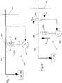
- FIG. 2is a diagram of a microgrid that includes a microsource implementing a unit power control scheme in accordance with an exemplary embodiment.
- FIG. 3is a diagram of a microgrid that includes a microsource implementing a zone power control scheme in accordance with an exemplary embodiment.
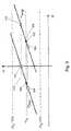
- FIG. 4is a graph depicting the relationship between steady state unit power vs. frequency for two exemplary microsources having different loads for use in a unit power control scheme in accordance with an exemplary embodiment.
- FIG. 5is a graph depicting the relationship between steady state zone power vs. frequency for two exemplary microsources having different loads for use in a zone power control scheme in accordance with an exemplary embodiment.
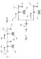
- FIG. 6is a diagram of two microsources used in a single zone in accordance with an exemplary embodiment.
- FIG. 7is a diagram of two microsources used in multiple zones in accordance with an exemplary embodiment.
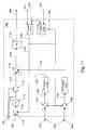
- FIG. 8is a block diagram of an energy storage control system for a distributed energy resource in accordance with an exemplary embodiment.
- FIG. 9is a block diagram of a voltage regulator of the energy storage control system of FIG. 8 in accordance with an exemplary embodiment.
- FIG. 10is a graph depicting a sliding window for applying storage power limits in accordance with an exemplary embodiment.
- FIG. 11is a block diagram of a droop controller of the energy storage control system of FIG. 8 in accordance with an exemplary embodiment.
- FIG. 12is a block diagram of a combined energy and power storage control system for a distributed energy resource in accordance with an exemplary embodiment.
- FIG. 13is a graph of an exemplary voltage droop regulation characteristic for a voltage regulator in accordance with an exemplary embodiment.
- a distributed energy resource (DER) system 100is shown in accordance with an exemplary embodiment.
- DERdistributed energy resource
- Such an exemplary systemis described, for example, in U.S. Pat. No. 7,116,010 and/or in U.S. Patent Publication No. 2006/000208574, the contents of which are incorporated by reference.
- the disclosure of the present applicationis limited by or in conflict with the disclosures of U.S. Pat. No. 7,116,010 and U.S. Patent Publication No. 2006/000208574, the disclosure of the present application controls.
- DER system 100may include a utility supply 102 connected to a feeder line 104 that interconnects one or more microsource systems 106 a , 106 b , 106 c , and 106 d and one or more loads 108 a , 108 b , and 108 c .
- DER system 100may include a plurality of feeder lines.
- Feeder line 104 , the one or more microsource systems 106 a , 106 b , 106 c , and 106 d , and the one or more loads 108 a , 108 b , and 108 ccan form a microgrid 110 .
- Utility supply 102can connect microgrid 110 to other similar microgrids distributed throughout DER system 100 .
- a microsource systemcan include exemplary microsource power sources, power storage, and power controllers.
- the power sourcecan be, for example, a fuel cell, hydroelectric generator, photovoltaic array, windmill, microturbine, etc.
- the power storageif present, can be, for example, a battery or flywheel.
- Feeder line 104may include one or more interface switches.
- An exemplary interface switchis described, for example, in U.S. patent application Ser. No. 11/266,976, filed Nov. 4, 2005 and entitled INTERFACE SWITCH FOR DISTRIBUTED ENERGY RESOURCES, the contents of which are incorporated by reference. Where the disclosure of the present application is limited by or in conflict with the disclosure of U.S. patent application Ser. No. 11/266,976, the disclosure of the present application controls.
- the interface switchif used, can be positioned between feeder line 104 and utility supply 102 so that microgrid 110 can be isolated from utility supply 102 . When microgrid 110 is isolated from utility supply 102 , the microgrid 110 is said to be operating in “island mode”.
- microgrid 110When microgrid 110 is connected to the utility supply 110 , the microgrid 110 is said to be operating in “grid mode”.
- the one or more loads 108 a , 108 b , and 108 cmay receive power from both the grid and local sources, depending on the current situational demands.
- microsourcesWhen a microsource or microgrid operates in island mode, load tracking problems can arise because typical power sources used in microsources, such as microturbines or fuel cells, tend to respond slowly, with time constants ranging from 10 to 200 seconds. Additionally, these types of power sources may be inertialess. Conventional utility power systems store energy in the inertia of the spinning mass of a generator. When a new load comes online, the initial energy balance can be met by the system's inertia, which results in a slight reduction in system frequency. Because power sources in microsources may be inertialess, a microsource may include power storage to ensure initial energy balance when loads are added during island mode.
- Each microsource system 106 a , 106 b , 106 c , and 106 dpreferably includes a microsource controller.
- the microsource controllerresponds to events using local information to respond to voltage drops, faults, blackouts, etc. and to switch to island operation mode as needed.
- the microsource controllercontrols the change in the output power of the system components as they change from a dispatched power mode to one in which frequency is controlled and load following is provided.
- Control schemes for a power controller in DER system 100can be classified into one of three broad classes: unit power control, zone power control, and a mixed system using both unit power control and zone power control.
- load changesare matched by a corresponding power injection from the utility because a microsource holds its injection to a set point P 0 .
- the microsourcematches the power demand as loads change.
- Each microsource system 106 a , 106 b , 106 c , and 106 dregulates the voltage magnitude at its connection point and the injected power using either a variable slope method or a fixed slope method.
- Each microsource system 106 a , 106 b , 106 c , and 106 dregulates the voltage magnitude at its connection point and the power that is flowing in the feeder.
- the microsource systems 106 a , 106 b , 106 c , and 106 dpick-up extra load demands, and as a result, show a constant load to the utility grid.
- DER system 100becomes a true dispatchable load as seen from the utility side supporting demand-side management arrangements.
- the symbol, Fis used for power flow in a zone and the symbol, P, is used for the power output from a microsource.
- load changesare matched by a different power injection from the microsource because the controller holds the flow of power coming from the grid, F line , to a constant value.
- all of the microsourcesparticipate in matching the power demand as loads change.
- Microgrid 200may include a microsource 202 and a load 108 .
- Microsource 202may be connected to feeder line 104 by an inductor 204 .
- An interface switchmay be provided, for example, in feeder line 104 . The interface switch can be opened to isolate microgrid 200 from the rest of DER system 100 and can be closed to connect microgrid 200 to the rest of DER system 100 .
- Microsource 202may include a controller capable of measuring a current through inductor 204 and of measuring a system voltage at a point 206 in feeder line 104 where inductor 204 joins feeder line 104 .
- Microgrid 300may include a microsource 302 and load 108 .
- Microsource 302may be connected to feeder line 104 by inductor 204 .
- An interface switchmay be provided, for example, in feeder line 104 . The interface switch can be opened to isolate microgrid 300 from the rest of DER system 100 and can be closed to connect microgrid 300 to the rest of DER system 100 .
- Microsource 302may include a controller capable of measuring a current at a point 304 in feeder line 104 between utility supply 102 and inductor 204 and of measuring a system voltage at a point 206 in feeder line 104 where inductor 204 joins feeder line 104 .
- FIG. 4shows steady state characteristics. The response may deviate from the characteristic during a transition period.
- Two exemplary microsources included in the microgridare shown. The microsources have different power set points though this is not required.
- a first microsourcehas a first power set point 402 .
- a second microsourcehas a second power set point 404 .
- First power set point 402 and second power set point 404are the amount of power injected by each source when connected to the grid at a system frequency ⁇ o .
- the slope of the characteristicis switched to vertical, as shown by the arrows, to move the first microsource frequency upwards to a fifth power set point 408 operating at ⁇ exp 412 .
- the resulting frequency of ⁇ imp 420will be smaller than the system frequency ⁇ o .
- the first microsourcemay move from the system frequency ⁇ o at first power set point 402 to a sixth power set point 414 operating at ⁇ imp 420 .
- the minimum and maximum power limitsare enforced by switching the characteristic with constant slope to a vertical steady state characteristic when the minimum or maximum power limit is reached.
- FIG. 5a graph depicting the relationship between steady state zone power and frequency using a fixed minimum slope method and zone power control is shown in accordance with an exemplary embodiment.
- Two exemplary microsourcesare included in the microgrid.
- the microsourceshave different power set points.
- a first microsourcehas a first flow set point 500 .
- a second microsourcehas a second flow set point 502 .
- F lineis the power (imported means positive) from the rest of DER system 100
- P sourceis the power injected or absorbed by microsource 302 .
- the power injected or absorbed by microsource 302is assumed: to be greater than the minimum power output, P min , of microsource 302 and less than the maximum power output, P max , of microsource 302 .
- P minis positive or zero
- P maxis the maximum power output
- Loadis the overall loading level seen by microsource 302 .
- the flow in the zonestracks the requested values at the system frequency ⁇ o .
- the two microsourcesreadjust the flow depending on the arrangement of the microsources with respect to each other and utility supply 102 .
- the relative location of loads and microsourcesis irrelevant, but when regulating zone power flow, the relative location of loads and microsources is important.
- a first microsource 604 and a second microsource 610are arranged in series in a single zone. The use of a single zone is for illustrative purposes only. There can be a greater or a lesser number of microsources in a single zone.
- the zoneincludes a first load 606 and a second load 612 on a local power bus 614 connected by an interface switch 600 to utility supply 102 .
- interface switch 600opens.
- a first flow 602 nearest to the utility systemis zero in island mode.
- a second flow 608may increase to compensate for the first flow 602 transition to zero.
- first flow 602moves from the system frequency ⁇ o , at first flow set point 500 to a third flow set point 510 operating at the frequency ⁇ exp 514 .
- Second flow 608moves from the system frequency ⁇ o at second flow set point 502 to a fourth power set point 512 .
- the systemoperates at frequency ⁇ exp 514 where first flow 602 is zero.
- Frequency ⁇ exp 514is larger than the nominal system frequency ⁇ o because the system was exporting to the grid (
- a first microsource 706 and a second microsource 710are arranged in parallel in two zones.
- the use of two zones each with a single microsourceis for illustrative purposes only. There can be a greater or a lesser number of microsources in a greater or a lesser number of zones.
- a first load 708is located on a first local power bus 714 connected by an interface switch 700 to utility supply 102 .
- a second load 712is located on a second local power bus 716 connected by interface switch 700 to utility supply 102 .
- a first flow 702flows through first local power bus 714
- a second flow 704flows through second local power bus 716 .
- the grid flowis the algebraic sum of first flow 702 and second flow 704 .
- interface switch 700opens.
- first flow 702moves from the system frequency ⁇ o at first flow set point 500 to a fifth flow set point 504 operating at the frequency ⁇ par 508 .
- Second flow 704moves from the system frequency ⁇ o at second flow set point 502 to a sixth power set point 506 at the frequency ⁇ par 508 .
- microsource system 800including an energy storage device 860 is shown in accordance with an exemplary embodiment.
- Microsource system 800 and its various componentsmay be implemented in or include hardware, firmware, software, and/or any combination of these methods.
- microsource system 800may include circuitry that can implement the processes indicated in the form of hardware, firmware, and/or a processor executing instructions embodied in software.
- Microsource system 800connects to a grid through feeder lines 802 .
- Feeder lines 802extend toward utility supply 102 in a first direction 804 and away from utility supply 102 in a second direction 806 .
- Microsource system 800connects to feeder lines 802 through bus lines 803 .
- Microsource system 800may include an inductor 824 , a transformer 850 , an inverter 852 , a voltage regulator 854 , a P- ⁇ droop controller 856 , a charging coordinator 858 , and energy storage device 860 .
- a first sensor 808measures a feeder current 814 through feeder lines 802 and transmits the measured feeder current to P- ⁇ droop controller 856 .
- a second sensor 810measures a feeder bus voltage at the connection point of bus lines 803 with feeder lines 802 , transmits the measured feeder bus voltage 816 to voltage regulator 854 , and transmits the measured feeder bus voltage 818 to P- ⁇ droop controller 856 .
- a third sensor 812measures an inverter current through bus lines 803 between transformer 850 and feeder lines 802 , transmits the measured inverter current 820 to voltage regulator 854 , and transmits the measured inverter current 822 to P- ⁇ droop controller 856 .
- Inverter 852connects to feeder lines 802 through inductance 824 and transformer 850 . Inverter 852 generates an output voltage at a phase angle of ⁇ . In general, the magnitude of ⁇ is small enough to satisfy the approximation sin( ⁇ ) ⁇ . This implies that power is linear relative to ⁇ . Voltage regulator 854 assists in decoupling interactions between DER microsources and includes a voltage vs. reactive power droop controller so that, as the reactive power Q generated by the inverter becomes more capacitive, a local voltage set point 826 is reduced. Conversely, as Q becomes more inductive, local voltage set point 826 is increased. P- ⁇ droop controller 856 provides the P- ⁇ and/or F- ⁇ functions described with reference to FIGS.
- P- ⁇ droop controller 856additionally provides control over energy storage device 860 using information from charging coordinator 858 .
- Charging coordinator 858controls the rate of charge and discharge and the charge levels of energy storage device 860 by setting power output limits on P- ⁇ droop controller 856 .
- Energy storage device 860connects with inverter 852 through a DC bus 842 .
- Voltage regulator 854may include a Q measured block 900 , a ⁇ block 902 , a magnitude block 904 , and a controller 906 .
- the local voltage set point 826is input to voltage regulator 854 .
- a regulated output voltage 828is output from voltage regulator 854 and input to inverter 852 . Creating an appropriate regulated output voltage at the terminals of inverter 852 regulates the feeder bus voltage.
- a reactive power 912is calculated in Q measured block 900 using the measured feeder bus voltage 816 and the measured inverter current 820 as inputs.
- the calculated reactive power 912is input to a ⁇ block 902 , which calculates a modified reactive power 914 .
- the modified reactive power 914is subtracted from local voltage set point 826 in a summer 908 to define a desired local voltage set point 916 based on a droop constant ⁇ defined in ⁇ block 902 .
- ⁇ block 902is implemented to exhibit a voltage vs. reactive current droop as shown with reference to FIG. 13 .
- Droop constant ⁇is the slope of the droop characteristic line 1300 .
- reactive power Qbecomes more inductive, the desired local voltage set point 916 becomes larger than the local voltage set point 826 .
- reactive power Q becomes more capacitivethe desired local voltage set point 916 becomes smaller than the local voltage set point 826 .
- the magnitude 918 of the measured feeder bus voltage 816is determined in magnitude block 904 .
- the magnitude 918 of the measured feeder bus voltage 816is compared to the desired local voltage set point 916 .
- a summer 910subtracts the magnitude 918 of the measured feeder bus voltage 816 from the desired local voltage set point 916 .
- the resulting voltage error 920is input to controller 906 to generate the regulated output voltage 828 .
- controller 906is a proportional-integral controller.
- Energy storage device 860normally operates in flow control mode with a F- ⁇ characteristic as shown in FIG. 5 . In some situations, energy storage device 860 may operate in unit power control mode with a P- ⁇ characteristic as shown in FIG. 4 . In either case, the limits of power from energy storage device 860 are used. With reference to FIG. 10 , the range of output power, P, available from energy storage device 860 imposes a window 1007 on feeder flow, F, such that P load ⁇ P max ⁇ F ⁇ P load ⁇ P min , where P load is the load on the system, and P max and P min are the limits on energy storage device 860 . When charging, P min is negative.
- a system F- ⁇ operating point 1000is defined for the system frequency ⁇ o .
- the limits for the feeder flow, Fcan be visualized on the F- ⁇ plane as a window whose width 1006 is the difference between F min 1002 and F max 1004 which equals the difference between P max and P min .
- the location of the window on the F-axisdepends on the value of P load . As P load increases, window 1007 slides to the right on the F- ⁇ plane. Conversely, if the load is reduced, window 1007 slides to the left on the F- ⁇ plane.
- An example flow set point 1008falls within window 1007 .
- Situationsare possible that can result in the flow set point falling outside window 1007 .
- load levels while connected to the grid, an incorrect choice for the flow set point, a change in output power of other microsources, and a transfer to island modeall can cause the flow set point to fall outside window 1007 .
- a first flow set point 1010falls to the left of window 1007 .
- P maxis exceeded.
- a second flow set point 1012falls to the right of window 1007 .
- P minis exceeded.
- the controlsreset the flow set point to the closest edge of window 1007 .
- P- ⁇ droop controller 856is shown in accordance with an exemplary embodiment.
- P- ⁇ droop controller 856may include a P measure block 1100 , a first summer 1102 , a first proportional-integral (PI) controller 1104 , a second summer 1106 , a second PI controller 1108 , an F measure block 1110 , a third summer 1112 , a multiplier 1114 , a fourth summer 1116 , a fifth summer 1118 , and an integrator 1120 .
- Inputs of P- ⁇ droop controller 856include the measured inverter current 822 , the measured feeder current 814 , and the measured feeder bus voltage 818 .
- inputs of P- ⁇ droop controller 856also include power limits 834 from charging coordinator 858 , a power set point 830 , and a frequency set point 832 .
- Outputs of P- ⁇ droop controller 856include an inverter phase angle 836 input to inverter 852 and a P meas 838 input to charging coordinator 858 .
- P- ⁇ droop controller 856may be used to provide zone power control or unit power control.
- power set point 830may be P o or F o and a power flow 1148 input to third summer 1112 may be F meas 1132 or P meas 838 .
- Inputs of F measure block 1110include the measured feeder current 814 and the measured feeder bus voltage 818 .
- F measure block 1110outputs F meas 1132 .
- Inputs of P measure block 1100include the measured inverter current 822 and the measured feeder bus voltage 818 .
- P measure block 1100outputs P meas 838 to first summer 1102 and second summer 1106 .
- P measure block 1100outputs P meas 838 to third summer 1112 . If unit power control is used, the sign of slope m in multiplier block 1114 is reversed. F measure block 1110 outputs F meas 1132 to third summer 1112 if zone power control is used.
- Power limits 834include a P max set point 1134 of energy storage device 860 and a P min set point 1140 of energy storage device 860 . Changing the limits P max and P min controls the width of window 1007 shown with reference to FIG. 10 .
- Charging coordinator 858controls the charge state of energy storage device 860 through the limits P max and P min .
- First summer 1102compares P max set point 1134 with P meas 838 to calculate a first power difference 1136 input to first PI controller 1104 . For example, first summer 1102 subtracts P meas 838 from P max set point 1134 .
- First PI controller 1104controls the maximum power through a maximum frequency change 1138 , ⁇ max , that is limited between a minimum frequency and 0 Hz.
- the minimum frequencyis ⁇ 1 Hz.
- Second summer 1106compares P min set point 1140 with P meas 838 to calculate a second power difference 1142 input to second PI controller 1108 . For example, second summer 1106 subtracts P meas 838 from P min set point 1140 .
- Second PI controller 1108controls the minimum power through a minimum frequency change 1144 , ⁇ min , that is limited between 0 Hz and a maximum frequency.
- the maximum frequencyis 1 Hz.
- ⁇ max and ⁇ minare scaled as radians for input to fifth summer 1118 .
- Maximum frequency change 1138 and minimum frequency change 1144maintain the flow set point within window 1007 .
- control parameters of the first and second PI controllers 1104 , 1108are set such that a steady state at a limit is reached in 10-20 cycles.
- Third summer 1112compares power set point 830 with power flow 1148 to calculate a third power difference 1150 input to multiplier 1114 .
- third summer 1112subtracts power flow 1148 from power set point 830 .
- Multiplier 1114multiplies third power difference 1150 by the slope m to determine a frequency change 1152 .
- frequency change 1152may be defined as m(F o ⁇ F meas ) or ⁇ m(P o ⁇ P meas ).
- Fourth summer 1116adds frequency set point 832 to frequency change 1152 to calculate an operating frequency 1154 input to fifth summer 1118 .
- Fifth summer 1118adds operating frequency 1154 with maximum frequency change 1138 and minimum frequency change 1144 to calculate a requested frequency 1156 input to integrator 1120 .
- the output of the integrator 1120is inverter phase angle 836 , which is rotating in time at frequency ⁇ req .
- Inverter phase angle 836is reset to zero when it exceeds 2 ⁇ radians.
- charging coordinator 858controls the rate of charge and discharge and the charge levels of energy storage device 860 by setting power limits 834 on P- ⁇ droop controller 856 . For example, if energy storage device 860 is fully charged, P max set point 1134 is set to zero, forcing the power set point 830 to match the effective load. Charging coordinator 858 can be implemented, for example, using a look up table or an analog circuit. Inputs to charging coordinator 858 include a charge level and a storage power 840 of energy storage device 860 and P meas 838 calculated by P- ⁇ droop controller 856 . The outputs are power limits 834 input to P- ⁇ droop controller 856 .
- Control of energy storage device 860utilizes two distinct parameters: 1) a storage power, P s , that determines how fast energy can be extracted or injected into energy storage device 860 , and 2) an energy level, E s , that can be stored in energy storage device 860 .
- the silicon devices in inverter 852may have a thermal upper bound that limits the peak current capabilities to about 2 pu of their nominal rated value.
- the resulting peak currentdefines a parameter ⁇ P peak .
- the output power from energy storage device 860has a rating P dis based on its preferred discharge rate and a rating P chg based on its preferred charge rate. These maximum charge and discharge rates are used when the distribution system requires the highest available level of power.
- P min and P max in P- ⁇ droop controller 856enforces the required rate limits. For example, to fix the discharge rate at P dis , P min and P max can be set to P dis . As a result, the other microsources increase or decrease their output as the loads change. Alternatively, to fix the discharge rate at P dis , P max can be set to P dis . As a result, energy storage device 860 tracks load changes without exceeding the ideal discharge rate, P dis .
- Charging coordinator 858also enforces energy levels to avoid overcharging energy storage device 860 and to ensure enough power supply to loads during island mode for a determined period of time. Again, these limits are enforced by P min and P max .
- a minimum energy level E mincorresponds with an energy level at which energy storage device 860 can only be charged because there is no available energy.
- a maximum energy level E maxcorresponds with an energy level at which energy storage device 860 can only be discharged because there is no available storage.
- a minimum reserve energy level E min — rescorresponds with the minimum reserve value of energy that energy storage device 860 maintains to provide short-term energy to loads during islanding.
- a maximum reserve energy level E max — rescorresponds with the maximum reserve value of energy that energy storage device 860 generally does not exceed except during a brief time in island operation.
- E min , E max , E min — res , and E max — resdictate the behavior of charging coordinator 858 .
- energy storage device 860In a first storage region, between E min — res and E max — res , the energy is considered within normal values.
- energy storage device 860In a second storage region, between E min and E min — res , energy storage device 860 is normally charged to a level between E min — res and E max — res , but can be discharged to balance power when islanding.
- energy storage device 860is normally discharged to a level between E min — res and E max — res , but can be charged to balance power when islanding.
- Energy storage device 860has high energy requirements to allow transfer of energy from low load periods to peak periods and high power requirements for load tracking and power quality needs. In general, if a battery is optimized for energy applications, recurring power demands, such as islanding or power quality events, tend to cause premature failure. Battery systems for bulk energy applications use such technologies as flow batteries and high-temperature batteries (such as sodium-sulfur and sodium-metal chloride). These need to be able to have continuous discharge over a specific time period. At the other end of the spectrum are uninterruptible power supply (UPS) systems or power battery applications, which demand high power discharge in seconds. To support both energy storage and power storage functions, a plurality of storage devices may be mounted in parallel. The rate of power change could be controlled using a ramp filter in P- ⁇ droop controller 856 , which controls the rate of change of the requested frequency 1156 , and therefore, the rate of power change.
- UPSuninterruptible power supply
- a power storage system 1200is connected to microsource system 800 in accordance with an exemplary embodiment to support high energy and high power requirements.
- Power storage system 1200may include an energy storage controller 1202 , a chopper controller 1204 , a power storage device 1206 , and a DC-DC chopper 1208 .
- Power storage system 1200connects to DC bus 842 between energy storage device 860 and inverter 852 through DC-DC chopper 1208 .
- Power storage system 1200provides a fast rate of energy, generally ⁇ 1 second, to inverter 852 .
- Energy storage controller 1202controls the rate of discharge of energy storage device 860 by measuring a DC current 1212 drawn by inverter 852 from energy storage device 860 .
- Energy storage controller 1202further receives a ramp rate 1210 as an input to calculate an output current 1214 .
- Output current 1214is input to chopper controller 1204 as an injected current reference which holds the power rate from energy storage device 860 to a maximum power ramp rate.
- Control of energy storage device 860 and power storage device 1206is coordinated through various input parameters.
- the basic coordinationis through the rate of charge or discharge.
- the discharge rateis provided by ramp rate 1210 through the energy storage controller.
- the charge rateis controlled by the limits provided by the charging coordinator 858 .
- ramp rate 1210may reduce the need for continually changing the power limits input to P- ⁇ droop controller 856 and may remove the need to enforce a rate limit on inverter 852 .
- the amount of power stored at power storage device 1206may be dictated by the amount of power required to make up the difference between what is needed by inverter 852 and what can be provided by energy storage device 860 .
Landscapes
- Engineering & Computer Science (AREA)
- Power Engineering (AREA)
- Supply And Distribution Of Alternating Current (AREA)
- Charge And Discharge Circuits For Batteries Or The Like (AREA)
Abstract
Description


allows power to change between P=0 and P=Pmaxas frequency changes over Δω. A
Claims (21)
Priority Applications (3)
| Application Number | Priority Date | Filing Date | Title |
|---|---|---|---|
| US11/681,024US7787272B2 (en) | 2007-03-01 | 2007-03-01 | Inverter based storage in dynamic distribution systems including distributed energy resources |
| PCT/US2008/054577WO2008109265A1 (en) | 2007-03-01 | 2008-02-21 | Inverter based storage in dynamic distribution systems including distributed energy resources |
| EP08730390AEP2132852A1 (en) | 2007-03-01 | 2008-02-21 | Inverter based storage in dynamic distribution systems including distributed energy resources |
Applications Claiming Priority (1)
| Application Number | Priority Date | Filing Date | Title |
|---|---|---|---|
| US11/681,024US7787272B2 (en) | 2007-03-01 | 2007-03-01 | Inverter based storage in dynamic distribution systems including distributed energy resources |
Publications (2)
| Publication Number | Publication Date |
|---|---|
| US20080212343A1 US20080212343A1 (en) | 2008-09-04 |
| US7787272B2true US7787272B2 (en) | 2010-08-31 |
Family
ID=39535816
Family Applications (1)
| Application Number | Title | Priority Date | Filing Date |
|---|---|---|---|
| US11/681,024Active2028-08-22US7787272B2 (en) | 2007-03-01 | 2007-03-01 | Inverter based storage in dynamic distribution systems including distributed energy resources |
Country Status (3)
| Country | Link |
|---|---|
| US (1) | US7787272B2 (en) |
| EP (1) | EP2132852A1 (en) |
| WO (1) | WO2008109265A1 (en) |
Cited By (14)
| Publication number | Priority date | Publication date | Assignee | Title |
|---|---|---|---|---|
| US20120306275A1 (en)* | 2011-06-02 | 2012-12-06 | Robert Bosch Gmbh | System and Method for Charging and Discharging a Li-ION Battery |
| US8781638B2 (en) | 2012-04-27 | 2014-07-15 | Gregory C. Rouse | Campus energy manager |
| US9312699B2 (en) | 2012-10-11 | 2016-04-12 | Flexgen Power Systems, Inc. | Island grid power supply apparatus and methods using energy storage for transient stabilization |
| US20160268818A1 (en)* | 2015-03-10 | 2016-09-15 | Lsis Co., Ltd. | Electricity providing system including battery energy storage system |
| US9472954B2 (en) | 2012-10-08 | 2016-10-18 | Eaton Corporation | Generator dispatching or load shedding control method and system for microgrid applications |
| US9553517B2 (en) | 2013-03-01 | 2017-01-24 | Fllexgen Power Systems, Inc. | Hybrid energy storage system and methods |
| US9564757B2 (en) | 2013-07-08 | 2017-02-07 | Eaton Corporation | Method and apparatus for optimizing a hybrid power system with respect to long-term characteristics by online optimization, and real-time forecasts, prediction or processing |
| US9923372B2 (en) | 2015-03-26 | 2018-03-20 | Toyota Motor Engineering & Manufacturing North America, Inc. | Energy management system |
| US9941696B2 (en) | 2014-04-06 | 2018-04-10 | CleanSpark Technologies LLC | Establishing communication and power sharing links between components of a distributed energy system |
| US9964978B2 (en) | 2015-04-14 | 2018-05-08 | Princeton Power Systems, Inc. | Control systems for microgrid power inverter and methods thereof |
| US10289080B2 (en) | 2012-10-11 | 2019-05-14 | Flexgen Power Systems, Inc. | Multi-generator applications using variable speed and solid state generators for efficiency and frequency stabilization |
| US10574055B2 (en) | 2014-12-30 | 2020-02-25 | Flexgen Power Systems, Inc. | Transient power stabilization device with active and reactive power control |
| US10734821B2 (en) | 2018-03-08 | 2020-08-04 | Saudi Arabian Oil Company | Power control system |
| EP4089872A1 (en)* | 2021-05-12 | 2022-11-16 | Hitachi, Ltd. | Power supply system, power supply management device, and power supply |
Families Citing this family (40)
| Publication number | Priority date | Publication date | Assignee | Title |
|---|---|---|---|---|
| US9721312B2 (en)* | 2007-03-21 | 2017-08-01 | Steven Y. Goldsmith | Customized electric power storage device for inclusion in a microgrid |
| US9263894B2 (en)* | 2007-03-21 | 2016-02-16 | Sandia Corporation | Customized electric power storage device for inclusion in a collective microgrid |
| US7839027B2 (en)* | 2008-10-09 | 2010-11-23 | The Aes Corporation | Frequency responsive charge sustaining control of electricity storage systems for ancillary services on an electrical power grid |
| US20100198420A1 (en)* | 2009-02-03 | 2010-08-05 | Optisolar, Inc. | Dynamic management of power production in a power system subject to weather-related factors |
| US8222765B2 (en)* | 2009-02-13 | 2012-07-17 | First Solar, Inc. | Photovoltaic power plant output |
| US8315745B2 (en) | 2009-04-24 | 2012-11-20 | Hunter Defense Technologies, Inc. | Mobile micro-grid power system controller and method |
| CN101877486B (en)* | 2009-04-30 | 2013-04-10 | 比亚迪股份有限公司 | Battery energy storage power station used for balancing power network load |
| CA2768459A1 (en)* | 2009-07-14 | 2011-01-20 | Enphase Energy, Inc. | Method and apparatus for identifying redeployed distributed generator components |
| BR112012003700A2 (en)* | 2009-08-19 | 2016-04-05 | Skytron Energy Gmbh | regulation for power plant |
| JPWO2011078151A1 (en)* | 2009-12-24 | 2013-05-09 | 三洋電機株式会社 | Power supply method, computer-readable recording medium, and power generation system |
| DE102010000838A1 (en)* | 2010-01-12 | 2011-07-14 | SkyWind GmbH, 24782 | Method and device for synchronizing a generator in a network |
| US8338987B2 (en)* | 2010-02-26 | 2012-12-25 | General Electric Company | Power generation frequency control |
| US8914158B2 (en)* | 2010-03-11 | 2014-12-16 | Aes Corporation, The | Regulation of contribution of secondary energy sources to power grid |
| US8478452B2 (en)* | 2010-04-06 | 2013-07-02 | Battelle Memorial Institute | Grid regulation services for energy storage devices based on grid frequency |
| EP2477298B1 (en) | 2011-01-15 | 2021-04-21 | GE Energy Power Conversion Technology Limited | Controllers for static energy supply units |
| US10879727B1 (en)* | 2011-05-26 | 2020-12-29 | James Carl Cooper | Power source load control |
| US11183843B1 (en)* | 2011-05-26 | 2021-11-23 | J. Carl Cooper | Power source load control |
| US11522365B1 (en)* | 2011-05-26 | 2022-12-06 | J. Carl Cooper | Inverter power source load dependent frequency control and load shedding |
| US9287714B2 (en)* | 2011-11-30 | 2016-03-15 | Michael Ropp | Method and system for island detection and anti-islanding protection in distributed power generation systems |
| CN103475018B (en)* | 2012-06-07 | 2016-06-08 | 北京能高自动化技术股份有限公司 | Based on the self-adaptation control method of grid-connected inverter of dynamic power grid resonant frequency identification |
| AU2013274314A1 (en)* | 2012-06-13 | 2015-01-22 | S&C Electric Company | Power grid photo-voltaic integration using distributed energy storage and management |
| JP5968719B2 (en)* | 2012-08-06 | 2016-08-10 | 京セラ株式会社 | Management system, management method, control device, and storage battery device |
| US9236763B2 (en)* | 2012-11-12 | 2016-01-12 | Dresser, Inc. | Device and method for distributing power at a remote pumping system |
| JP6081178B2 (en)* | 2012-12-14 | 2017-02-15 | 株式会社日立製作所 | Power converter and control method of power converter |
| JP5633872B1 (en) | 2013-02-08 | 2014-12-03 | 日本電気株式会社 | Battery control device, battery control system, battery control method, and recording medium |
| CN103236710B (en)* | 2013-04-12 | 2016-05-25 | 国家电网公司 | Adopt the THE UPFC of modular construction |
| JP6455661B2 (en)* | 2014-12-24 | 2019-01-23 | 富士電機株式会社 | Independent operation system |
| US10008854B2 (en) | 2015-02-19 | 2018-06-26 | Enphase Energy, Inc. | Method and apparatus for time-domain droop control with integrated phasor current control |
| US9971371B2 (en)* | 2015-03-17 | 2018-05-15 | Mitsubishi Electric Research Laboratories, Inc. | Method for predicting a voltage collapse in a micro-grid connected to a power distribution network |
| EP3308444B1 (en)* | 2015-06-12 | 2020-01-29 | Enphase Energy, Inc. | Method and apparatus for control of intelligent loads in microgrids |
| WO2017012650A1 (en)* | 2015-07-20 | 2017-01-26 | Abb Schweiz Ag | Feeder power flow control within a microgrid |
| CN105186673A (en)* | 2015-10-27 | 2015-12-23 | 厦门大学 | Multi-energy-storage solar charging station based on slide average filter |
| WO2018213273A1 (en)* | 2017-05-15 | 2018-11-22 | Dynapower Company Llc | Method and system for extracting excess power |
| JP6640925B2 (en)* | 2017-05-29 | 2020-02-05 | 京セラ株式会社 | Management system, management method, control device, and storage battery device |
| CN107403284A (en)* | 2017-08-10 | 2017-11-28 | 新奥泛能网络科技股份有限公司 | The computational methods of distributed energy resource system primary energy comprehensive utilization ratio |
| US11862979B1 (en)* | 2019-10-11 | 2024-01-02 | Mohd Hasan Ali | Triple-function battery energy storage system for hybrid microgrid system |
| US11404907B2 (en)* | 2019-11-25 | 2022-08-02 | Hitachi Energy Switzerland Ag | Distributed voltage control for power networks |
| FR3131120A1 (en)* | 2021-12-17 | 2023-06-23 | Electricite De France | Device, method and computer program for controlling a voltage source |
| CN117578536B (en)* | 2023-10-19 | 2024-06-18 | 上海勘测设计研究院有限公司 | Network-structured energy storage control method and system for weak alternating current system |
| US12322974B1 (en)* | 2024-01-04 | 2025-06-03 | Michael Ropp | Method and apparatus for detection of arbitrarily located single-phase open circuits by inverter-based resources |
Citations (38)
| Publication number | Priority date | Publication date | Assignee | Title |
|---|---|---|---|---|
| US4096394A (en) | 1975-03-25 | 1978-06-20 | A.G. fur industrielle Elektronic AGIE | Apparatus for supplying electrical energy to a load |
| US4315163A (en) | 1980-09-16 | 1982-02-09 | Frank Bienville | Multipower electrical system for supplying electrical energy to a house or the like |
| US5041959A (en) | 1990-08-14 | 1991-08-20 | General Electric Company | Control system for a current source converter supplying an AC bus |
| US5198698A (en) | 1991-02-11 | 1993-03-30 | Best Power Technology, Inc. | Auxiliary power supply system for providing dc power on demand |
| US5329222A (en) | 1992-11-30 | 1994-07-12 | Westinghouse Electric Corporation | Apparatus and method for dynamic voltage restoration of utility distribution networks |
| US5536976A (en) | 1994-03-03 | 1996-07-16 | Gas Research Institute | Multiple service load solid state switching for controlled cogeneration system |
| US5559704A (en) | 1992-11-23 | 1996-09-24 | General Electric Company | Method to compute horsepower required by an internal combustion engine coupled to an auxiliary alternator |
| US5563802A (en) | 1994-01-26 | 1996-10-08 | Onan Corporation | Generator power system and method |
| US5596492A (en) | 1994-06-14 | 1997-01-21 | Electric Power Research Institute, Inc. | Method and apparatus for de-centralized signal frequency restoration in a distributed UPS system |
| US5614770A (en) | 1994-06-06 | 1997-03-25 | Helionetics, Inc. | Structure and method for performing active injection mode filtering on an AC power system |
| US5710699A (en) | 1996-05-28 | 1998-01-20 | General Electric Company | Power electronic interface circuits for batteries and ultracapacitors in electric vehicles and battery storage systems |
| US5745356A (en) | 1996-06-25 | 1998-04-28 | Exide Electronics Corporation | Independent load sharing of AC power systems connected in parallel |
| US5811960A (en) | 1996-10-02 | 1998-09-22 | United Power Corporation | Battery-less uninterruptable sequel power supply |
| US6014015A (en) | 1997-08-08 | 2000-01-11 | Alpha Technologies, Inc. | Electrical generator employing rotary engine |
| US6111764A (en) | 1998-10-12 | 2000-08-29 | Sanyo Denki Co., Ltd. | Power failure-free power supply apparatus |
| US6134124A (en) | 1999-05-12 | 2000-10-17 | Abb Power T&D Company Inc. | Universal distributed-resource interface |
| US6172432B1 (en) | 1999-06-18 | 2001-01-09 | Gen-Tran Corporation | Automatic transfer switch |
| US6188205B1 (en) | 1999-03-09 | 2001-02-13 | Mitsubishi Denki Kabushiki Kaisha | Power system control apparatus and power system control method |
| US6219591B1 (en) | 1998-05-15 | 2001-04-17 | Abb Power T&D Company Inc. | Voltage instability predictor (VIP)—method and system for performing adaptive control to improve voltage stability in power systems |
| US6219623B1 (en) | 1997-11-24 | 2001-04-17 | Plug Power, Inc. | Anti-islanding method and apparatus for distributed power generation |
| US6249411B1 (en) | 1999-10-07 | 2001-06-19 | International Business Machines Corporation | Over-voltage protection circuit and method for preventing system shutdown in a power system employing multiple power supplies |
| US6252310B1 (en) | 1999-07-28 | 2001-06-26 | Nextek Power Systems, Inc. | Balanced modular power management system and method |
| US6285917B1 (en) | 1996-12-03 | 2001-09-04 | Kabushiki Kaisha Toshiba | Electric power system protection and control system and distributed control system |
| US6288456B1 (en) | 1998-05-19 | 2001-09-11 | Sure Power Corporation | Power system |
| US6347027B1 (en) | 1997-11-26 | 2002-02-12 | Energyline Systems, Inc. | Method and apparatus for automated reconfiguration of an electric power distribution system with enhanced protection |
| US6356471B1 (en) | 2000-07-10 | 2002-03-12 | Powerware Corporation | Dynamic feedback adaptive control system and method for paralleling electric power sources and an uninterruptible power supply including same |
| US6359423B1 (en) | 1999-10-19 | 2002-03-19 | Kabushiki Kaisha Toshiba | Method and system for suppressing a voltage fluctuation in a power system |
| US6465910B2 (en) | 2001-02-13 | 2002-10-15 | Utc Fuel Cells, Llc | System for providing assured power to a critical load |
| US20030036806A1 (en) | 2001-06-25 | 2003-02-20 | Schienbein Lawrence A. | Modular, integrated power conversion and energy management system |
| EP1286444A2 (en) | 2001-08-21 | 2003-02-26 | Institut für Solare Energieversorgungstechnik (ISET) Verein an der Gesamthochschule Kassel e.V. | Device for parallel operation of equal range single-phase or three-phase voltage sources |
| EP1383224A1 (en) | 2001-04-27 | 2004-01-21 | Kabushiki Kaisha Kobe Seiko sho | Hybrid construction equipment power control apparatus |
| US20040051387A1 (en)* | 2002-09-17 | 2004-03-18 | Lasseter Robert H. | Control of small distributed energy resources |
| US20040080165A1 (en) | 2001-12-31 | 2004-04-29 | Capstone Turbine Corporation | Turbogenerator/motor controller with ancillary energy storage/discharge |
| US6787933B2 (en) | 2001-01-10 | 2004-09-07 | Capstone Turbine Corporation | Power generation system having transient ride-through/load-leveling capabilities |
| US6812586B2 (en) | 2001-01-30 | 2004-11-02 | Capstone Turbine Corporation | Distributed power system |
| US6870279B2 (en) | 1998-01-05 | 2005-03-22 | Capstone Turbine Corporation | Method and system for control of turbogenerator power and temperature |
| US7042110B2 (en) | 2003-05-07 | 2006-05-09 | Clipper Windpower Technology, Inc. | Variable speed distributed drive train wind turbine system |
| US20060208574A1 (en) | 2005-03-18 | 2006-09-21 | Wisconsin Alumni Research Foundation | Control of small distributed energy resources |
- 2007
- 2007-03-01USUS11/681,024patent/US7787272B2/enactiveActive
- 2008
- 2008-02-21EPEP08730390Apatent/EP2132852A1/ennot_activeWithdrawn
- 2008-02-21WOPCT/US2008/054577patent/WO2008109265A1/enactiveApplication Filing
Patent Citations (41)
| Publication number | Priority date | Publication date | Assignee | Title |
|---|---|---|---|---|
| US4096394A (en) | 1975-03-25 | 1978-06-20 | A.G. fur industrielle Elektronic AGIE | Apparatus for supplying electrical energy to a load |
| US4315163A (en) | 1980-09-16 | 1982-02-09 | Frank Bienville | Multipower electrical system for supplying electrical energy to a house or the like |
| US5041959A (en) | 1990-08-14 | 1991-08-20 | General Electric Company | Control system for a current source converter supplying an AC bus |
| US5198698A (en) | 1991-02-11 | 1993-03-30 | Best Power Technology, Inc. | Auxiliary power supply system for providing dc power on demand |
| US5559704A (en) | 1992-11-23 | 1996-09-24 | General Electric Company | Method to compute horsepower required by an internal combustion engine coupled to an auxiliary alternator |
| US5329222A (en) | 1992-11-30 | 1994-07-12 | Westinghouse Electric Corporation | Apparatus and method for dynamic voltage restoration of utility distribution networks |
| US5563802A (en) | 1994-01-26 | 1996-10-08 | Onan Corporation | Generator power system and method |
| US5536976A (en) | 1994-03-03 | 1996-07-16 | Gas Research Institute | Multiple service load solid state switching for controlled cogeneration system |
| US5614770A (en) | 1994-06-06 | 1997-03-25 | Helionetics, Inc. | Structure and method for performing active injection mode filtering on an AC power system |
| US5596492A (en) | 1994-06-14 | 1997-01-21 | Electric Power Research Institute, Inc. | Method and apparatus for de-centralized signal frequency restoration in a distributed UPS system |
| US5710699A (en) | 1996-05-28 | 1998-01-20 | General Electric Company | Power electronic interface circuits for batteries and ultracapacitors in electric vehicles and battery storage systems |
| US5745356A (en) | 1996-06-25 | 1998-04-28 | Exide Electronics Corporation | Independent load sharing of AC power systems connected in parallel |
| US5811960A (en) | 1996-10-02 | 1998-09-22 | United Power Corporation | Battery-less uninterruptable sequel power supply |
| US6285917B1 (en) | 1996-12-03 | 2001-09-04 | Kabushiki Kaisha Toshiba | Electric power system protection and control system and distributed control system |
| US6014015A (en) | 1997-08-08 | 2000-01-11 | Alpha Technologies, Inc. | Electrical generator employing rotary engine |
| US6219623B1 (en) | 1997-11-24 | 2001-04-17 | Plug Power, Inc. | Anti-islanding method and apparatus for distributed power generation |
| US6347027B1 (en) | 1997-11-26 | 2002-02-12 | Energyline Systems, Inc. | Method and apparatus for automated reconfiguration of an electric power distribution system with enhanced protection |
| US6870279B2 (en) | 1998-01-05 | 2005-03-22 | Capstone Turbine Corporation | Method and system for control of turbogenerator power and temperature |
| US6219591B1 (en) | 1998-05-15 | 2001-04-17 | Abb Power T&D Company Inc. | Voltage instability predictor (VIP)—method and system for performing adaptive control to improve voltage stability in power systems |
| US6288456B1 (en) | 1998-05-19 | 2001-09-11 | Sure Power Corporation | Power system |
| US6111764A (en) | 1998-10-12 | 2000-08-29 | Sanyo Denki Co., Ltd. | Power failure-free power supply apparatus |
| US6188205B1 (en) | 1999-03-09 | 2001-02-13 | Mitsubishi Denki Kabushiki Kaisha | Power system control apparatus and power system control method |
| US6134124A (en) | 1999-05-12 | 2000-10-17 | Abb Power T&D Company Inc. | Universal distributed-resource interface |
| US6172432B1 (en) | 1999-06-18 | 2001-01-09 | Gen-Tran Corporation | Automatic transfer switch |
| US6252310B1 (en) | 1999-07-28 | 2001-06-26 | Nextek Power Systems, Inc. | Balanced modular power management system and method |
| US6249411B1 (en) | 1999-10-07 | 2001-06-19 | International Business Machines Corporation | Over-voltage protection circuit and method for preventing system shutdown in a power system employing multiple power supplies |
| US6359423B1 (en) | 1999-10-19 | 2002-03-19 | Kabushiki Kaisha Toshiba | Method and system for suppressing a voltage fluctuation in a power system |
| US6356471B1 (en) | 2000-07-10 | 2002-03-12 | Powerware Corporation | Dynamic feedback adaptive control system and method for paralleling electric power sources and an uninterruptible power supply including same |
| US6787933B2 (en) | 2001-01-10 | 2004-09-07 | Capstone Turbine Corporation | Power generation system having transient ride-through/load-leveling capabilities |
| US6812586B2 (en) | 2001-01-30 | 2004-11-02 | Capstone Turbine Corporation | Distributed power system |
| US6465910B2 (en) | 2001-02-13 | 2002-10-15 | Utc Fuel Cells, Llc | System for providing assured power to a critical load |
| EP1383224A1 (en) | 2001-04-27 | 2004-01-21 | Kabushiki Kaisha Kobe Seiko sho | Hybrid construction equipment power control apparatus |
| US7069673B2 (en) | 2001-04-27 | 2006-07-04 | Kabushiki Kaisha Kobe Seiko Sho (Kobe Steel, Ltd.) | Hybrid construction equipment power control apparatus |
| US20030036806A1 (en) | 2001-06-25 | 2003-02-20 | Schienbein Lawrence A. | Modular, integrated power conversion and energy management system |
| EP1286444A2 (en) | 2001-08-21 | 2003-02-26 | Institut für Solare Energieversorgungstechnik (ISET) Verein an der Gesamthochschule Kassel e.V. | Device for parallel operation of equal range single-phase or three-phase voltage sources |
| US6693809B2 (en) | 2001-08-21 | 2004-02-17 | Institut Fuer Solare Energieversorgungstechnik (Iset) Verein An Der Universitaet Gesamthochschule Kassel E.V. | Device for equal-rated parallel operation of single-or three-phase voltage sources |
| US20040080165A1 (en) | 2001-12-31 | 2004-04-29 | Capstone Turbine Corporation | Turbogenerator/motor controller with ancillary energy storage/discharge |
| US20040051387A1 (en)* | 2002-09-17 | 2004-03-18 | Lasseter Robert H. | Control of small distributed energy resources |
| US7116010B2 (en) | 2002-09-17 | 2006-10-03 | Wisconsin Alumni Research Foundation | Control of small distributed energy resources |
| US7042110B2 (en) | 2003-05-07 | 2006-05-09 | Clipper Windpower Technology, Inc. | Variable speed distributed drive train wind turbine system |
| US20060208574A1 (en) | 2005-03-18 | 2006-09-21 | Wisconsin Alumni Research Foundation | Control of small distributed energy resources |
Non-Patent Citations (9)
| Title |
|---|
| DOE News, The DER Weekly, vol. 2, No. 10, pp. 1-4. Mar. 9, 2001. |
| Lasseter, Robert, "MicroGrids," IEEE, No. 0-7803-7322-7, pp. 305-308. Jul. 2002. |
| Lasseter, Robert, et al. "White Paper on Integration of Distributed Energy Resources the CERTS MicroGrid Concept," Consortium for Electric Reliability Technology Solutions, pp. 1-27. Apr. 2002. |
| Lasseter, Robert, Kevin Tomsovic, and Paolo Piagi. "Scenarios for Distributed Technology Applications with Steady State and Dynamic Models of Loads and Micro-Sources," Consortium for Electric Reliability Technology Solutions. Apr. 14, 2000. |
| Notice of Allowance issued in U.S. Appl. No. 11/681,014 mailed July 30, 2009. |
| PCT International Search Report for PCT/US2008/054566 dated Jul. 11, 2008. |
| PCT International Search Report for PCT/US2008/054572 dated Jul. 11, 2008. |
| PCT International Search Report for PCT/US2008/054577 dated Jul. 11, 2008. |
| Son, Kwang, et al., "A Newton-Type Current Injection Model of UPFC for Studying Low-Frequency Oscillations," Power Engineering Society General Meeting, IEEE vol. 4, Jul. 13-17, 2003. (Abstract). |
Cited By (21)
| Publication number | Priority date | Publication date | Assignee | Title |
|---|---|---|---|---|
| US8760118B2 (en)* | 2011-06-02 | 2014-06-24 | Robert Bosch Gmbh | System and method for charging and discharging a Li-ion battery |
| US20120306275A1 (en)* | 2011-06-02 | 2012-12-06 | Robert Bosch Gmbh | System and Method for Charging and Discharging a Li-ION Battery |
| US8781638B2 (en) | 2012-04-27 | 2014-07-15 | Gregory C. Rouse | Campus energy manager |
| US9472954B2 (en) | 2012-10-08 | 2016-10-18 | Eaton Corporation | Generator dispatching or load shedding control method and system for microgrid applications |
| US10008853B2 (en) | 2012-10-08 | 2018-06-26 | Eaton Intelligent Power Limited | Generator dispatching or load shedding control method and system for microgrid applications |
| US10615597B2 (en) | 2012-10-11 | 2020-04-07 | Flexgen Power Systems, Inc. | Grid power supply apparatus and methods using energy storage for transient stabilization |
| US10289080B2 (en) | 2012-10-11 | 2019-05-14 | Flexgen Power Systems, Inc. | Multi-generator applications using variable speed and solid state generators for efficiency and frequency stabilization |
| US9312699B2 (en) | 2012-10-11 | 2016-04-12 | Flexgen Power Systems, Inc. | Island grid power supply apparatus and methods using energy storage for transient stabilization |
| US9553517B2 (en) | 2013-03-01 | 2017-01-24 | Fllexgen Power Systems, Inc. | Hybrid energy storage system and methods |
| US9564757B2 (en) | 2013-07-08 | 2017-02-07 | Eaton Corporation | Method and apparatus for optimizing a hybrid power system with respect to long-term characteristics by online optimization, and real-time forecasts, prediction or processing |
| US9941696B2 (en) | 2014-04-06 | 2018-04-10 | CleanSpark Technologies LLC | Establishing communication and power sharing links between components of a distributed energy system |
| US10658839B2 (en) | 2014-04-06 | 2020-05-19 | Cleanspark, Inc. | Establishing communication and power sharing links between components of a distributed energy system |
| US11581732B2 (en) | 2014-04-06 | 2023-02-14 | Fortress Power Llc | Establishing communication and power sharing links between components of a distributed energy system |
| US12170443B2 (en) | 2014-04-06 | 2024-12-17 | Fortress Power Llc | Establishing communication and power sharing links between components of a distributed energy system |
| US10574055B2 (en) | 2014-12-30 | 2020-02-25 | Flexgen Power Systems, Inc. | Transient power stabilization device with active and reactive power control |
| US20160268818A1 (en)* | 2015-03-10 | 2016-09-15 | Lsis Co., Ltd. | Electricity providing system including battery energy storage system |
| US10090685B2 (en)* | 2015-03-10 | 2018-10-02 | Lsis Co., Ltd. | Electricity providing system including battery energy storage system |
| US9923372B2 (en) | 2015-03-26 | 2018-03-20 | Toyota Motor Engineering & Manufacturing North America, Inc. | Energy management system |
| US9964978B2 (en) | 2015-04-14 | 2018-05-08 | Princeton Power Systems, Inc. | Control systems for microgrid power inverter and methods thereof |
| US10734821B2 (en) | 2018-03-08 | 2020-08-04 | Saudi Arabian Oil Company | Power control system |
| EP4089872A1 (en)* | 2021-05-12 | 2022-11-16 | Hitachi, Ltd. | Power supply system, power supply management device, and power supply |
Also Published As
| Publication number | Publication date |
|---|---|
| EP2132852A1 (en) | 2009-12-16 |
| US20080212343A1 (en) | 2008-09-04 |
| WO2008109265A1 (en) | 2008-09-12 |
Similar Documents
| Publication | Publication Date | Title |
|---|---|---|
| US7787272B2 (en) | Inverter based storage in dynamic distribution systems including distributed energy resources | |
| US7920942B2 (en) | Control of combined storage and generation in distributed energy resources | |
| Pannala et al. | Effective control and management scheme for isolated and grid connected DC microgrid | |
| Datta et al. | Battery energy storage system control for mitigating PV penetration impact on primary frequency control and state-of-charge recovery | |
| US10923919B2 (en) | Method and apparatus for controlling power flow in a hybrid power system | |
| US7715950B2 (en) | Non-inverter based distributed energy resource for use in a dynamic distribution system | |
| US7687937B2 (en) | Control of small distributed energy resources | |
| Molina | Distributed energy storage systems for applications in future smart grids | |
| Colson et al. | A review of challenges to real-time power management of microgrids | |
| US10554047B2 (en) | Control method of an electric microgrid | |
| US7116010B2 (en) | Control of small distributed energy resources | |
| Nazaripouya et al. | Nergy storage in microgrids: challenges, applications and research need | |
| Sun et al. | Implementation and CHIL testing of a microgrid control system | |
| Yasin et al. | Fuzzy logic power management for a PV/wind microgrid with backup and storage systems | |
| Yasin | Energy management of a stand-alone DC microgrid based on PV/Wind/Battery/Diesel Gen. combined with super-capacitor | |
| Karaki et al. | Frequency and voltage restoration for droop controlled AC microgrids | |
| Singh et al. | Small-signal modeling and stability analysis of autonomous direct current microgrid with distributed energy storage system | |
| Fang et al. | Power management of virtual synchronous generators through using hybrid energy storage systems | |
| Atcitty et al. | Battery energy storage system | |
| Loh et al. | Autonomous operation of hybrid AC-DC microgrids with progressive energy flow tuning | |
| Pozo et al. | Battery energy storage system for a hybrid generation system grid connected using fuzzy controllers | |
| Ghosh et al. | Energy management techniques to enhance DC-bus voltage transient stability and power balancing issues for islanded DC microgrids | |
| Jingang et al. | Research on Frequency and Voltage Control Strategy of Virtual Synchronous Generator for Island Wide Microgrid | |
| Ahmad | Real-Time Control and Power Management for Interconnected Microgrids with Self-Healing Capability | |
| Prajapati et al. | Intelligent Frequency Regulation under a Deregulated Control System Using Distributed Energy Storage Systems |
Legal Events
| Date | Code | Title | Description |
|---|---|---|---|
| AS | Assignment | Owner name:WISCONSIN ALUMNI RESEARCH FOUNDATION, WISCONSIN Free format text:ASSIGNMENT OF ASSIGNORS INTEREST;ASSIGNORS:LASSETER, ROBERT H;PIAGI, PAOLO;REEL/FRAME:019584/0198;SIGNING DATES FROM 20070426 TO 20070501 Owner name:WISCONSIN ALUMNI RESEARCH FOUNDATION, WISCONSIN Free format text:ASSIGNMENT OF ASSIGNORS INTEREST;ASSIGNORS:LASSETER, ROBERT H;PIAGI, PAOLO;SIGNING DATES FROM 20070426 TO 20070501;REEL/FRAME:019584/0198 | |
| STCF | Information on status: patent grant | Free format text:PATENTED CASE | |
| CC | Certificate of correction | ||
| CC | Certificate of correction | ||
| CC | Certificate of correction | ||
| FEPP | Fee payment procedure | Free format text:PAT HOLDER NO LONGER CLAIMS SMALL ENTITY STATUS, ENTITY STATUS SET TO UNDISCOUNTED (ORIGINAL EVENT CODE: STOL); ENTITY STATUS OF PATENT OWNER: LARGE ENTITY | |
| FPAY | Fee payment | Year of fee payment:4 | |
| MAFP | Maintenance fee payment | Free format text:PAYMENT OF MAINTENANCE FEE, 8TH YEAR, LARGE ENTITY (ORIGINAL EVENT CODE: M1552) Year of fee payment:8 | |
| AS | Assignment | Owner name:UNITED STATES DEPARTMENT OF ENERGY, DISTRICT OF COLUMBIA Free format text:CONFIRMATORY LICENSE;ASSIGNOR:UNIVERSITY OF WISCONSIN-MADISON;REEL/FRAME:054647/0565 Effective date:20100520 | |
| MAFP | Maintenance fee payment | Free format text:PAYMENT OF MAINTENANCE FEE, 12TH YEAR, LARGE ENTITY (ORIGINAL EVENT CODE: M1553); ENTITY STATUS OF PATENT OWNER: LARGE ENTITY Year of fee payment:12 |