US7787270B2 - DC-DC and DC-AC power conversion system - Google Patents
DC-DC and DC-AC power conversion systemDownload PDFInfo
- Publication number
- US7787270B2 US7787270B2US11/810,825US81082507AUS7787270B2US 7787270 B2US7787270 B2US 7787270B2US 81082507 AUS81082507 AUS 81082507AUS 7787270 B2US7787270 B2US 7787270B2
- Authority
- US
- United States
- Prior art keywords
- isolated
- conversion system
- power conversion
- phase
- galvanic
- Prior art date
- Legal status (The legal status is an assumption and is not a legal conclusion. Google has not performed a legal analysis and makes no representation as to the accuracy of the status listed.)
- Active - Reinstated, expires
Links
- 238000006243chemical reactionMethods0.000titleclaimsabstractdescription48
- HBMJWWWQQXIZIP-UHFFFAOYSA-Nsilicon carbideChemical compound[Si+]#[C-]HBMJWWWQQXIZIP-UHFFFAOYSA-N0.000claimsdescription36
- 229910010271silicon carbideInorganic materials0.000claimsdescription36
- 239000004065semiconductorSubstances0.000claimsdescription12
- 238000002955isolationMethods0.000claimsdescription10
- 239000003990capacitorSubstances0.000claimsdescription9
- 238000001914filtrationMethods0.000claimsdescription6
- XUIMIQQOPSSXEZ-UHFFFAOYSA-NSiliconChemical compound[Si]XUIMIQQOPSSXEZ-UHFFFAOYSA-N0.000claimsdescription4
- 230000009471actionEffects0.000claimsdescription4
- 229910052710siliconInorganic materials0.000claimsdescription4
- 239000010703siliconSubstances0.000claimsdescription4
- 230000001360synchronised effectEffects0.000claimsdescription4
- 230000002457bidirectional effectEffects0.000claims2
- 238000011144upstream manufacturingMethods0.000claims2
- 238000010586diagramMethods0.000description10
- 238000000034methodMethods0.000description5
- XEEYBQQBJWHFJM-UHFFFAOYSA-NIronChemical group[Fe]XEEYBQQBJWHFJM-UHFFFAOYSA-N0.000description4
- 238000012986modificationMethods0.000description3
- 230000004048modificationEffects0.000description3
- 230000003071parasitic effectEffects0.000description3
- 238000013459approachMethods0.000description2
- 230000004888barrier functionEffects0.000description2
- 230000008901benefitEffects0.000description2
- 230000003137locomotive effectEffects0.000description2
- 238000004806packaging method and processMethods0.000description2
- 238000011084recoveryMethods0.000description2
- 238000011160researchMethods0.000description2
- 239000007787solidSubstances0.000description2
- 230000009286beneficial effectEffects0.000description1
- 230000015556catabolic processEffects0.000description1
- 238000013016dampingMethods0.000description1
- 238000006731degradation reactionMethods0.000description1
- 238000013461designMethods0.000description1
- 238000011161developmentMethods0.000description1
- 238000009413insulationMethods0.000description1
- 230000010354integrationEffects0.000description1
- 238000004519manufacturing processMethods0.000description1
- 239000000463materialSubstances0.000description1
- 239000002707nanocrystalline materialSubstances0.000description1
- 230000007935neutral effectEffects0.000description1
- 238000012545processingMethods0.000description1
- 230000007704transitionEffects0.000description1
Images


Classifications
- H—ELECTRICITY
- H02—GENERATION; CONVERSION OR DISTRIBUTION OF ELECTRIC POWER
- H02J—CIRCUIT ARRANGEMENTS OR SYSTEMS FOR SUPPLYING OR DISTRIBUTING ELECTRIC POWER; SYSTEMS FOR STORING ELECTRIC ENERGY
- H02J4/00—Circuit arrangements for mains or distribution networks not specified as AC or DC
- H—ELECTRICITY
- H02—GENERATION; CONVERSION OR DISTRIBUTION OF ELECTRIC POWER
- H02M—APPARATUS FOR CONVERSION BETWEEN AC AND AC, BETWEEN AC AND DC, OR BETWEEN DC AND DC, AND FOR USE WITH MAINS OR SIMILAR POWER SUPPLY SYSTEMS; CONVERSION OF DC OR AC INPUT POWER INTO SURGE OUTPUT POWER; CONTROL OR REGULATION THEREOF
- H02M1/00—Details of apparatus for conversion
- H02M1/14—Arrangements for reducing ripples from DC input or output
- H—ELECTRICITY
- H02—GENERATION; CONVERSION OR DISTRIBUTION OF ELECTRIC POWER
- H02M—APPARATUS FOR CONVERSION BETWEEN AC AND AC, BETWEEN AC AND DC, OR BETWEEN DC AND DC, AND FOR USE WITH MAINS OR SIMILAR POWER SUPPLY SYSTEMS; CONVERSION OF DC OR AC INPUT POWER INTO SURGE OUTPUT POWER; CONTROL OR REGULATION THEREOF
- H02M7/00—Conversion of AC power input into DC power output; Conversion of DC power input into AC power output
- H02M7/02—Conversion of AC power input into DC power output without possibility of reversal
- H02M7/04—Conversion of AC power input into DC power output without possibility of reversal by static converters
- H02M7/12—Conversion of AC power input into DC power output without possibility of reversal by static converters using discharge tubes with control electrode or semiconductor devices with control electrode
- H02M7/21—Conversion of AC power input into DC power output without possibility of reversal by static converters using discharge tubes with control electrode or semiconductor devices with control electrode using devices of a triode or transistor type requiring continuous application of a control signal
- H02M7/217—Conversion of AC power input into DC power output without possibility of reversal by static converters using discharge tubes with control electrode or semiconductor devices with control electrode using devices of a triode or transistor type requiring continuous application of a control signal using semiconductor devices only
- H—ELECTRICITY
- H02—GENERATION; CONVERSION OR DISTRIBUTION OF ELECTRIC POWER
- H02M—APPARATUS FOR CONVERSION BETWEEN AC AND AC, BETWEEN AC AND DC, OR BETWEEN DC AND DC, AND FOR USE WITH MAINS OR SIMILAR POWER SUPPLY SYSTEMS; CONVERSION OF DC OR AC INPUT POWER INTO SURGE OUTPUT POWER; CONTROL OR REGULATION THEREOF
- H02M1/00—Details of apparatus for conversion
- H02M1/0067—Converter structures employing plural converter units, other than for parallel operation of the units on a single load
- H02M1/007—Plural converter units in cascade
Definitions
- the present inventionis directed to power electronics, and more particularly to a DC-DC and DC-AC power conversion system with galvanic isolation and with DC input voltages derived from a combination of three single-phase and three-phase AC-DC converters.
- FIG. 1exemplifies the large number of cells, or levels, required in these cascaded converter block architectures. These architectures are disadvantageous in that they inherently necessitate a high level of complexity and part count. A large number of cascaded cells are required with this approach due to limited voltage ratings of available Si semiconductors.
- FIG. 2exemplifies the large number of cells, or levels, required in a multi-level NPC converter block architecture.
- the architecture illustrated in FIG. 2utilizes a HV-IGBT-based multi-level NPC converter configuration on the primary side.
- the limited voltage rating and switching frequency of current high voltage IGBTsresult in a large component count and low system performance.
- High power density solid-state electronics transformers for solid-state power substationsprovide functionalities beyond a conventional line frequency iron core transformer. These functionalities include: (1) step up or down voltage level with galvanic isolation between low frequency input and output, which is the function of a conventional line frequency transformer, with a much higher power density resulted from intermediate high frequency isolation transformer; (2) ability to convert output frequency, e.g. get DC or 60 Hz or 400 Hz power at the output from 50 Hz or 60 Hz input power; (3) generate multiple outputs at different frequencies and voltage levels; and (4) provide advanced control functions for entire power system, such as reactive power compensation, voltage regulation, and active harmonic filtering, active damping etc.
- SiC MOSFETSiC MOSFET
- SiC BJTSiC Schottky
- PiNIntegrated Network
- JBS diodesetc. offer application benefits, such as lower conduction and switching losses, higher voltage and higher temperature capabilities than their counterparts of Si devices.
- Those featuresare critical to implementation of a high density high frequency medium voltage SSPS.
- those SiC devicespresently have a yield that is lower than Si devices, and a cost that is higher than Si devices.
- Significant challengesremain to developing such a smaller solid state electronics transformer for a solid-state power substation (SSPS). These include, but are not limited to:
- Passive componentssuch as DC bus capacitors, input and output filters, and contactors can limit power densities. Minimizing the use of such devices is critical;
- DC-DC and DC-AC power converterthat is suitable for implementing a power conversion system (i.e. solid-state power substation (SSPS)) including controls to minimize all passive components associated with the SSPS.
- SSPSsolid-state power substation
- the present inventionis directed to a galvanic isolated DC-DC or DC-AC power conversion system that is coupled to a plurality of DC sources which are derived from a combination of a plurality of single-phase and three-phase AC-DC converters.
- the DC-DC or DC-AC converters including a rectification stage at the secondary side of a high frequency transformertogether comprise a mixed silicon-carbide (SiC) and silicon (Si) device topology.
- Each galvanically isolated DC-DC or DC-AC converterin another embodiment, comprises a pulse width modulated H-bridge with all silicon carbide (SiC) power switches or mixed SiC and Si power switches.
- SiCsilicon carbide
- the galvanic isolated DC-DC or DC-AC power conversion system in still embodimentis configured to provide mixed type outputs (mixed frequency, e.g. DC with 50 or 60 Hz, with 400 Hz; mixed voltage levels).
- mixed type outputse.g. DC with 50 or 60 Hz, with 400 Hz; mixed voltage levels.
- FIG. 1illustrates an electronic transformer architecture that employs cascaded converter blocks to handle high voltages on the primary side, and that is known in the art
- FIG. 2illustrates an electronic transformer architecture that employs a multi-level NPC converter block architecture, and that is known in the art
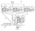
- FIG. 3illustrates a power conversion system (solid-state power substation (SSPS)) using a plurality of DC-DC power converters, according to one embodiment of the present invention
- FIG. 4is a schematic diagram illustrating more detail of a single DC-DC power converter architecture for one of the DC-DC power converters shown in FIG. 3 ;
- FIG. 5illustrates a direct AC inversion to generate single-phase AC voltage, which results from a sinusoidal high frequency modulated waveform at the transformer shown in FIG. 4 and filtering action with leakage inductance of the high frequency transformer (and/or with additional inductance) and the DC link capacitor of the direct AC inverter.
- the low frequency modulated, e.g. half sinusoidal, DC voltage at the DC link of the direct AC inverteris unfolded to obtain the ultimate low frequency AC output.
- Three-phase AC voltagecan be obtained with three sets of the circuit depicted in FIG. 5 ;
- FIG. 6is a high level diagram illustrating the power conversion system using a plurality of DC-DC power converters shown in FIG. 3 , in which a SiC bridge has failed in one of the DC-DC converters and the failed cell is bypassed;
- FIG. 7is a high level diagram illustrating the power conversion system using a plurality of DC-DC power converters shown in FIG. 3 , in which a SiC bridge has failed in one of the DC-DC converters and the failed cell is disconnected;
- FIG. 8is a waveform diagram illustrating line current waveforms for the two operating modes when a SiC fails as shown in FIGS. 6 and 7 respectively in which the top waveform corresponds to FIG. 6 and the bottom waveform corresponds to FIG. 7 ;
- FIG. 9is a block diagram illustrating a power conversion system with a mixed type output according to one embodiment of the present invention.
- FIG. 3illustrates a power conversion system (solid-state power substation (SSPS)) 10 that employs a plurality of modular DC-DC and DC-AC power converters, each including a high frequency galvanic isolation transformer 24 , to provide a form and fit replacement for a conventional iron core transformer.
- SSPSsolid-state power substation
- 3is based upon 1) rectification of high voltage AC to high voltage DC links by using a Si SCR or diode bridge 16 combined with SiC MOSFET H-bridges 18 ; 2) modular SiC MOSFET H-bridge DC-DC converters 14 inverting high voltage DC links to high frequency AC links; 3) modular high frequency transformers 24 coupled to the high frequency AC links; 4) rectifiers 19 at the secondary side of the high frequency transformers 24 to create a DC bus 25 ; and 5) output power block 50 to construct a desired AC voltage output signal.
- Each DC-DC converter 14can be seen to include a modular H-bridge DC-DC power converter with a galvanic isolation high frequency transformer 24 .
- the outputs of these DC-DC power converters 14can be placed in parallel to provide a fault tolerant DC bus 25 , as shown in FIG. 3 .
- the present inventionis not so limited however, and it shall be understood that the power conversion system 10 can provide numerous combinations of output voltages and types of output voltages, depending only on where the output voltage is generated by the power conversion system 10 . Different DC voltages can be generated, for example, by changing the turns ratio of one or more transformers 24 .
- Direct AC inversioncan be use to generate single-phase AC voltage, which results from a sinusoidal high frequency modulated waveform at the transformer 24 and filtering action with leakage inductance of the high frequency transformer (and/or with additional inductance) and the DC link capacitor of the direct AC inverter described herein below with reference to FIG. 5 .
- the low frequency modulated, e.g. half sinusoidal DC voltage at the DC link of the direct AC inverteris unfolded to obtain the ultimate low frequency AC output.
- Three-phase AC voltagecan be obtained with three sets of the circuit depicted in FIG. 5 .
- Mixed multiple types of outputs(DC only, DC w/60 Hz w/400 Hz outputs, . . . , etc.) can thus be provided using the techniques described above.
- a separate DC-AC convertercan also be added onto the common DC link 25 to provide a functional replacement of a conventional transformer.
- FIG. 4is a schematic diagram illustrating in more detail, a single DC-DC converter 14 .
- Each DC-DC converter 14includes a SiC MOSFET full bridge 27 coupled to an Si or SiC diode bridge 29 through a high frequency galvanic isolation transformer 24 .
- the transformer 24 outputsare rectified via a set of Si fast recovery diodes 31 or SiC Schottky diodes, and then filtered via a reactor/inductor 33 and a filter capacitor 35 to provide a DC output.
- DC-DC converter 14in one embodiment employs a SiC MOSFET H-bridge topology common to all DC-DC converters 14 , and also common to other portions of the power conversion system 10 .
- This simple H-bridge building blockwas found by the present inventors to enable a topology having minimized commutation loops and parasitic inductance. These features can be important since tight packaging and integration of the modules are important for high frequency operation with minimized electrical and EMI stresses.
- the H-bridge based DC-DC converter 14can be readily adapted for phase-shifted soft-switching if MOSFET and antiparallel diode 21 switching losses prove to be unacceptable with hard-switched operation. Multi-level NPC converters would require significant modifications to accommodate such soft-switched operation, and thus are disadvantageous when compared with the H-bridge based DC-DC converter 14 .
- the phase-shifting technique employedexploits parasitic circuit elements, such as device capacitances, to provide low-loss switching transitions without the need for additional components. Suitable phase-shifting techniques are widely used in commercial DC-DC power supplies, and so phase-shifting techniques will not be discussed in detail herein.
- the DC-DC converter 14 topologyalso advantageously leads to the use of modular lower power high frequency transformers 24 .
- This featureallows easier procurement and manufacturing of magnetic cores because processing of high frequency and high power magnetic cores, such as nanocrystalline material, for large cores is a significant challenge.
- the foregoing modular high frequency transformers 24can have higher power density than a single transformer solution due to distributed thermal management and less insulation requirements.
- the size and weight of the high voltage DC link capacitor 32can therefore be dramatically reduced.
- the DC-DC converter 14can also be controlled with respect to every other DC-DC converter 14 by interleaving multiple threads to minimize switching frequency ripple and thus the size and weight of the output filters 33 , 35 . Further, phase shifting techniques associated with the DC-DC converter output can be implemented to achieve soft switching, reduced EMI, and high performance. Interleaving and phase shifting are well known in the digital and analog arts, and so are not discussed in further detail herein to preserve brevity and enhance clarity.
- SiC MOSFETbody diodes
- PiN or JBSantiparallel diodes
- the SiC MOSFETsmay be operated in a synchronous rectifier mode to further improve their efficiency. Operating the SiC MOSFETs in a synchronous rectifier mode will alleviate the necessity to employ antiparallel diodes in the SiC modules.
- FIG. 5illustrates a direct AC inversion 100 to generate a single-phase AC voltage, which results from a sinusoidal high frequency modulated waveform at the transformer and filtering action with leakage inductance of the high frequency transformer (and/or with additional inductance) and the DC link capacitor of the direct AC inverter.
- the low frequency modulated, e.g. half sinusoidal, DC voltage at the DC link of the direct AC inverteris unfolded to obtain the ultimate low frequency AC output.
- Three-phase AC voltagecan be obtained with three sets of the circuit 100 depicted in FIG. 5 .
- FIG. 6a high level diagram illustrates the power conversion system 10 using a plurality of DC-DC power converters 14 shown in FIG. 3 , in which a SiC bridge 17 has failed in one of the DC-DC converters 14 , and the failed cell is bypassed.
- FIG. 7is a high level diagram illustrating the power conversion system 10 using a plurality of DC-DC power converters 14 shown in FIG. 3 , in which a SiC bridge 17 has failed in one of the DC-DC converters 14 , and the failed cell is disconnected.
- FIG. 8is a waveform diagram illustrating line current waveforms for the two operating modes when a SiC fails as shown in FIGS. 6 and 7 respectively in which the top waveform corresponds to the condition shown in FIG. 6 and the bottom waveform corresponds to the condition shown in FIG. 7 . All three phases A, B, C are still connected to the grid and can draw current during the operating condition depicted in FIG. 6 , while no current is flowing in the isolated phase A depicted in FIG. 7 .
- FIG. 9is a block diagram illustrating a power conversion system 200 with a mixed type output according to one embodiment of the present invention.
- the power conversion system 200corresponds to the power conversion system 10 , but now is also configured to provide different level DC voltage outputs 202 , 204 and different frequency AC voltage outputs 206 , 208 .
- three phase ACis depicted, single phase AC or any other desired combination of AC and DC voltages can just as easily be provided using appropriate configurations.
- a modular DC-DC converter 14provides a form and fit replacement for a conventional iron core transformer.
- the DC-DC converter 14includes modular soft-switched SiC MOSFET H-bridges 17 , each coupled to its own high-voltage DC bus from an AC-DC stage 12 .
- each DC-DC converter 14converts a high voltage DC link voltage to a common DC voltage through an associated high frequency galvanic isolation transformer and low voltage rectifier.
- the DC-DC converters 14are controlled in a way that (a) input ripple power from the SiC H-bridges 18 in each phase of the AC-DC stage 12 is canceled at a common DC bus to minimize high-voltage DC link capacitance; and (b) interleaving of multiple threads cancels the switching frequency ripple so that the output filter can be minimized. (c) Soft-switching of DC-DC power converters 14 can be achieved through phase shifted, soft-switching PWM H-bridges. Another embodiment employs direct AC inversion to produce a desired AC output from the AC link resulting in maximum power density and efficiency.
Landscapes
- Engineering & Computer Science (AREA)
- Power Engineering (AREA)
- Dc-Dc Converters (AREA)
Abstract
Description
Claims (23)
Priority Applications (1)
| Application Number | Priority Date | Filing Date | Title |
|---|---|---|---|
| US11/810,825US7787270B2 (en) | 2007-06-06 | 2007-06-06 | DC-DC and DC-AC power conversion system |
Applications Claiming Priority (1)
| Application Number | Priority Date | Filing Date | Title |
|---|---|---|---|
| US11/810,825US7787270B2 (en) | 2007-06-06 | 2007-06-06 | DC-DC and DC-AC power conversion system |
Publications (2)
| Publication Number | Publication Date |
|---|---|
| US20080304296A1 US20080304296A1 (en) | 2008-12-11 |
| US7787270B2true US7787270B2 (en) | 2010-08-31 |
Family
ID=40095724
Family Applications (1)
| Application Number | Title | Priority Date | Filing Date |
|---|---|---|---|
| US11/810,825Active - Reinstated2028-04-01US7787270B2 (en) | 2007-06-06 | 2007-06-06 | DC-DC and DC-AC power conversion system |
Country Status (1)
| Country | Link |
|---|---|
| US (1) | US7787270B2 (en) |
Cited By (30)
| Publication number | Priority date | Publication date | Assignee | Title |
|---|---|---|---|---|
| US20070151272A1 (en)* | 2006-01-03 | 2007-07-05 | York International Corporation | Electronic control transformer using DC link voltage |
| US20100014325A1 (en)* | 2008-07-15 | 2010-01-21 | General Electric Company | Ac-ac converter with high frequency link |
| US20100238692A1 (en)* | 2009-03-20 | 2010-09-23 | Cree, Inc. | Rectifier with sic bipolar junction transistor rectifying elements |
| US20100259098A1 (en)* | 2009-04-08 | 2010-10-14 | Lear Corporation | Vehicle inverter for powering consumer electronic devices |
| US20110133573A1 (en)* | 2009-12-07 | 2011-06-09 | Illinois Tool Works Inc. | Ground power unit for aircraft |
| US20120126733A1 (en)* | 2010-11-19 | 2012-05-24 | El-Refaie Ayman Mohamed Fawzi | High power-density, high back emf permanent magnet machine and method of making same |
| US20120274139A1 (en)* | 2011-04-29 | 2012-11-01 | General Electric Company | Switching coordination of distributed dc-dc converters for highly efficient photovoltaic power plants |
| CN103715912A (en)* | 2013-11-22 | 2014-04-09 | 哈尔滨宏宇整流开关厂 | Intelligent temperature control device of mold pressing platform variable-frequency power source |
| US8736102B1 (en)* | 2010-10-07 | 2014-05-27 | The Boeing Company | Multifunctional power converter |
| US8811038B2 (en) | 2011-11-11 | 2014-08-19 | Gridco, Inc. | Apparatus and method for soft switching in a medium voltage to low voltage converter |
| US20150249401A1 (en)* | 2012-01-27 | 2015-09-03 | Kk-Electronic A/S | Control system for power stacks in a power converter, power converter with such control system and wind turbine with such power converter |
| US9318974B2 (en) | 2014-03-26 | 2016-04-19 | Solaredge Technologies Ltd. | Multi-level inverter with flying capacitor topology |
| US20160211763A1 (en)* | 2015-01-19 | 2016-07-21 | Delta Electronics, Inc. | Wind power conversion system |
| US9537423B2 (en) | 2012-09-24 | 2017-01-03 | General Electric Company | Power conversion system |
| US9685900B2 (en) | 2010-11-19 | 2017-06-20 | General Electric Company | Low-inductance, high-efficiency induction machine and method of making same |
| US9722511B2 (en) | 2012-12-07 | 2017-08-01 | General Electric Company | Systems and methods for controlling an electrical power supply |
| US9780682B2 (en) | 2015-10-05 | 2017-10-03 | Resilient Power Systems, LLC | Power management utilizing synchronous common coupling |
| US9941813B2 (en) | 2013-03-14 | 2018-04-10 | Solaredge Technologies Ltd. | High frequency multi-level inverter |
| US9942964B2 (en) | 2016-08-12 | 2018-04-10 | Honeywell International Inc. | Constant current regulator for airfield ground lighting |
| US10027240B1 (en)* | 2017-01-06 | 2018-07-17 | General Electric Company | Ground fault isolation for power converters with silicon carbide MOSFETs |
| US10148205B2 (en)* | 2017-02-02 | 2018-12-04 | General Electric Company | Control method for power converters with inverter blocks with silicon carbide MOSFETs |
| US10153712B2 (en)* | 2017-05-15 | 2018-12-11 | Virginia Tech Intellectual Properties, Inc. | Circulating current injection control |
| US10608545B2 (en) | 2015-10-05 | 2020-03-31 | Resilient Power Systems, LLC | Power management utilizing synchronous common coupling |
| US10770970B2 (en) | 2017-06-09 | 2020-09-08 | Ford Global Technologies, Llc | Flying capacitor based variable voltage converter |
| CN112292804A (en)* | 2018-04-30 | 2021-01-29 | 通用电气公司 | Control method of power converter with inverter block with silicon carbide MOSFETs |
| US11394302B2 (en) | 2020-08-10 | 2022-07-19 | Terminal Power LLC | DC-DC auto-converter module |
| TWI779585B (en)* | 2020-05-14 | 2022-10-01 | 台達電子工業股份有限公司 | Multi-phase ac/dc converter |
| EP4156482A1 (en)* | 2021-09-28 | 2023-03-29 | Schneider Electric IT Corporation | A novel approach for dc to ac inversion |
| US20240014758A1 (en)* | 2020-11-19 | 2024-01-11 | Sanden Corporation | Power conversion device |
| US11923716B2 (en) | 2019-09-13 | 2024-03-05 | Milwaukee Electric Tool Corporation | Power converters with wide bandgap semiconductors |
Families Citing this family (103)
| Publication number | Priority date | Publication date | Assignee | Title |
|---|---|---|---|---|
| GB2415841B (en)* | 2004-11-08 | 2006-05-10 | Enecsys Ltd | Power conditioning unit |
| US10693415B2 (en) | 2007-12-05 | 2020-06-23 | Solaredge Technologies Ltd. | Testing of a photovoltaic panel |
| US11881814B2 (en) | 2005-12-05 | 2024-01-23 | Solaredge Technologies Ltd. | Testing of a photovoltaic panel |
| US8405367B2 (en) | 2006-01-13 | 2013-03-26 | Enecsys Limited | Power conditioning units |
| GB2434490B (en) | 2006-01-13 | 2009-04-01 | Enecsys Ltd | Power conditioning unit |
| US9088178B2 (en) | 2006-12-06 | 2015-07-21 | Solaredge Technologies Ltd | Distributed power harvesting systems using DC power sources |
| US8319483B2 (en) | 2007-08-06 | 2012-11-27 | Solaredge Technologies Ltd. | Digital average input current control in power converter |
| US11888387B2 (en) | 2006-12-06 | 2024-01-30 | Solaredge Technologies Ltd. | Safety mechanisms, wake up and shutdown methods in distributed power installations |
| US11735910B2 (en) | 2006-12-06 | 2023-08-22 | Solaredge Technologies Ltd. | Distributed power system using direct current power sources |
| US8384243B2 (en) | 2007-12-04 | 2013-02-26 | Solaredge Technologies Ltd. | Distributed power harvesting systems using DC power sources |
| US8473250B2 (en) | 2006-12-06 | 2013-06-25 | Solaredge, Ltd. | Monitoring of distributed power harvesting systems using DC power sources |
| US8963369B2 (en) | 2007-12-04 | 2015-02-24 | Solaredge Technologies Ltd. | Distributed power harvesting systems using DC power sources |
| US11855231B2 (en) | 2006-12-06 | 2023-12-26 | Solaredge Technologies Ltd. | Distributed power harvesting systems using DC power sources |
| US12316274B2 (en) | 2006-12-06 | 2025-05-27 | Solaredge Technologies Ltd. | Pairing of components in a direct current distributed power generation system |
| US8618692B2 (en) | 2007-12-04 | 2013-12-31 | Solaredge Technologies Ltd. | Distributed power system using direct current power sources |
| US8947194B2 (en) | 2009-05-26 | 2015-02-03 | Solaredge Technologies Ltd. | Theft detection and prevention in a power generation system |
| US11309832B2 (en) | 2006-12-06 | 2022-04-19 | Solaredge Technologies Ltd. | Distributed power harvesting systems using DC power sources |
| US11296650B2 (en) | 2006-12-06 | 2022-04-05 | Solaredge Technologies Ltd. | System and method for protection during inverter shutdown in distributed power installations |
| US9112379B2 (en) | 2006-12-06 | 2015-08-18 | Solaredge Technologies Ltd. | Pairing of components in a direct current distributed power generation system |
| US8816535B2 (en) | 2007-10-10 | 2014-08-26 | Solaredge Technologies, Ltd. | System and method for protection during inverter shutdown in distributed power installations |
| US8319471B2 (en) | 2006-12-06 | 2012-11-27 | Solaredge, Ltd. | Battery power delivery module |
| US9130401B2 (en) | 2006-12-06 | 2015-09-08 | Solaredge Technologies Ltd. | Distributed power harvesting systems using DC power sources |
| US11569659B2 (en) | 2006-12-06 | 2023-01-31 | Solaredge Technologies Ltd. | Distributed power harvesting systems using DC power sources |
| US11687112B2 (en) | 2006-12-06 | 2023-06-27 | Solaredge Technologies Ltd. | Distributed power harvesting systems using DC power sources |
| US8013472B2 (en) | 2006-12-06 | 2011-09-06 | Solaredge, Ltd. | Method for distributed power harvesting using DC power sources |
| US7994657B2 (en)* | 2006-12-22 | 2011-08-09 | Solarbridge Technologies, Inc. | Modular system for unattended energy generation and storage |
| US7786622B2 (en)* | 2007-03-01 | 2010-08-31 | Graco Children's Products Inc. | Juvenile product inductive power transfer |
| US7755916B2 (en) | 2007-10-11 | 2010-07-13 | Solarbridge Technologies, Inc. | Methods for minimizing double-frequency ripple power in single-phase power conditioners |
| US9291696B2 (en) | 2007-12-05 | 2016-03-22 | Solaredge Technologies Ltd. | Photovoltaic system power tracking method |
| US11264947B2 (en) | 2007-12-05 | 2022-03-01 | Solaredge Technologies Ltd. | Testing of a photovoltaic panel |
| CN105244905B (en) | 2007-12-05 | 2019-05-21 | 太阳能安吉有限公司 | Release mechanism in distributed power device is waken up and method for closing |
| WO2009072076A2 (en) | 2007-12-05 | 2009-06-11 | Solaredge Technologies Ltd. | Current sensing on a mosfet |
| WO2009073867A1 (en) | 2007-12-05 | 2009-06-11 | Solaredge, Ltd. | Parallel connected inverters |
| EP2235807B1 (en) | 2007-12-20 | 2019-05-08 | SolarCity Corporation | Grid synchronisation |
| US8111052B2 (en) | 2008-03-24 | 2012-02-07 | Solaredge Technologies Ltd. | Zero voltage switching |
| US7888819B2 (en)* | 2008-04-23 | 2011-02-15 | Phoenixtec Power Co., Ltd. | Multi-input power converter and uninterruptible power supply having the same |
| EP2294669B8 (en) | 2008-05-05 | 2016-12-07 | Solaredge Technologies Ltd. | Direct current power combiner |
| CA2751492C (en)* | 2009-02-11 | 2014-08-12 | Tomas U. Jonsson | Method in a cascaded two-level converter, control device and computer program products |
| US8482947B2 (en) | 2009-07-31 | 2013-07-09 | Solarbridge Technologies, Inc. | Apparatus and method for controlling DC-AC power conversion |
| CA2714820A1 (en)* | 2009-09-09 | 2011-03-09 | Universite Du Quebec A Trois-Rivieres | Power converter system and method |
| US8462518B2 (en) | 2009-10-12 | 2013-06-11 | Solarbridge Technologies, Inc. | Power inverter docking system for photovoltaic modules |
| US12418177B2 (en) | 2009-10-24 | 2025-09-16 | Solaredge Technologies Ltd. | Distributed power system using direct current power sources |
| US8824178B1 (en) | 2009-12-31 | 2014-09-02 | Solarbridge Technologies, Inc. | Parallel power converter topology |
| EP2524422B1 (en) | 2010-01-11 | 2018-05-09 | Philips Lighting Holding B.V. | Ac/dc converter circuit |
| EP2372893B1 (en)* | 2010-03-31 | 2012-06-27 | Ce+T | Multilevel inverter |
| GB2482653B (en) | 2010-06-07 | 2012-08-29 | Enecsys Ltd | Solar photovoltaic systems |
| US8503200B2 (en) | 2010-10-11 | 2013-08-06 | Solarbridge Technologies, Inc. | Quadrature-corrected feedforward control apparatus and method for DC-AC power conversion |
| US8279649B2 (en) | 2010-10-11 | 2012-10-02 | Solarbridge Technologies, Inc. | Apparatus and method for controlling a power inverter |
| US9160408B2 (en) | 2010-10-11 | 2015-10-13 | Sunpower Corporation | System and method for establishing communication with an array of inverters |
| US10673222B2 (en) | 2010-11-09 | 2020-06-02 | Solaredge Technologies Ltd. | Arc detection and prevention in a power generation system |
| US10230310B2 (en) | 2016-04-05 | 2019-03-12 | Solaredge Technologies Ltd | Safety switch for photovoltaic systems |
| GB2485527B (en) | 2010-11-09 | 2012-12-19 | Solaredge Technologies Ltd | Arc detection and prevention in a power generation system |
| US10673229B2 (en) | 2010-11-09 | 2020-06-02 | Solaredge Technologies Ltd. | Arc detection and prevention in a power generation system |
| US8842454B2 (en) | 2010-11-29 | 2014-09-23 | Solarbridge Technologies, Inc. | Inverter array with localized inverter control |
| US9467063B2 (en) | 2010-11-29 | 2016-10-11 | Sunpower Corporation | Technologies for interleaved control of an inverter array |
| GB2486408A (en) | 2010-12-09 | 2012-06-20 | Solaredge Technologies Ltd | Disconnection of a string carrying direct current |
| GB2483317B (en) | 2011-01-12 | 2012-08-22 | Solaredge Technologies Ltd | Serially connected inverters |
| US8193788B2 (en) | 2011-04-27 | 2012-06-05 | Solarbridge Technologies, Inc. | Method and device for controlling a configurable power supply to provide AC and/or DC power output |
| US9065354B2 (en) | 2011-04-27 | 2015-06-23 | Sunpower Corporation | Multi-stage power inverter for power bus communication |
| US8611107B2 (en) | 2011-04-27 | 2013-12-17 | Solarbridge Technologies, Inc. | Method and system for controlling a multi-stage power inverter |
| US8922185B2 (en) | 2011-07-11 | 2014-12-30 | Solarbridge Technologies, Inc. | Device and method for global maximum power point tracking |
| US8570005B2 (en) | 2011-09-12 | 2013-10-29 | Solaredge Technologies Ltd. | Direct current link circuit |
| US8284574B2 (en) | 2011-10-17 | 2012-10-09 | Solarbridge Technologies, Inc. | Method and apparatus for controlling an inverter using pulse mode control |
| FR2982092B1 (en)* | 2011-11-02 | 2015-01-02 | Valeo Systemes De Controle Moteur | POWER MODULE AND ELECTRIC DEVICE FOR POWER SUPPLY AND CHARGING COMBINED WITH ACCUMULATOR AND MOTOR |
| GB2497275A (en) | 2011-11-25 | 2013-06-12 | Enecsys Ltd | Modular adjustable power factor renewable energy inverter system |
| GB2498365A (en) | 2012-01-11 | 2013-07-17 | Solaredge Technologies Ltd | Photovoltaic module |
| GB2498790A (en) | 2012-01-30 | 2013-07-31 | Solaredge Technologies Ltd | Maximising power in a photovoltaic distributed power system |
| GB2498791A (en) | 2012-01-30 | 2013-07-31 | Solaredge Technologies Ltd | Photovoltaic panel circuitry |
| US9853565B2 (en) | 2012-01-30 | 2017-12-26 | Solaredge Technologies Ltd. | Maximized power in a photovoltaic distributed power system |
| GB2499991A (en) | 2012-03-05 | 2013-09-11 | Solaredge Technologies Ltd | DC link circuit for photovoltaic array |
| US10115841B2 (en) | 2012-06-04 | 2018-10-30 | Solaredge Technologies Ltd. | Integrated photovoltaic panel circuitry |
| US9276635B2 (en) | 2012-06-29 | 2016-03-01 | Sunpower Corporation | Device, system, and method for communicating with a power inverter using power line communications |
| CA2884599A1 (en) | 2012-09-13 | 2014-03-20 | Moog Inc. | Active voltage bus system and method |
| US9385620B1 (en) | 2013-01-10 | 2016-07-05 | Lockheed Martin Corporation | AC link converter switch engine |
| WO2014152948A2 (en) | 2013-03-14 | 2014-09-25 | Engineered Electric Company | Bidirectional power converter |
| US9548619B2 (en) | 2013-03-14 | 2017-01-17 | Solaredge Technologies Ltd. | Method and apparatus for storing and depleting energy |
| EP3506370B1 (en) | 2013-03-15 | 2023-12-20 | Solaredge Technologies Ltd. | Bypass mechanism |
| US9584044B2 (en) | 2013-03-15 | 2017-02-28 | Sunpower Corporation | Technologies for converter topologies |
| US9564835B2 (en) | 2013-03-15 | 2017-02-07 | Sunpower Corporation | Inverter communications using output signal |
| US9882507B2 (en) | 2013-04-16 | 2018-01-30 | Solarcity Corporation | Power factor adjustment in multi-phase power system |
| CN104811073B (en)* | 2014-01-24 | 2019-05-31 | 通用电气能源电能变换科技有限公司 | Converter module, device, system and correlation technique |
| US9621063B2 (en) | 2015-03-11 | 2017-04-11 | DRS Consolidated Controls, Inc. | Reference current generation in bidirectional power converter |
| US9698700B2 (en) | 2015-03-11 | 2017-07-04 | DRS Consolidated Controls, Inc. | Predictive current control in bidirectional power converter |
| US12057807B2 (en) | 2016-04-05 | 2024-08-06 | Solaredge Technologies Ltd. | Chain of power devices |
| US11018623B2 (en) | 2016-04-05 | 2021-05-25 | Solaredge Technologies Ltd. | Safety switch for photovoltaic systems |
| US11177663B2 (en) | 2016-04-05 | 2021-11-16 | Solaredge Technologies Ltd. | Chain of power devices |
| US10840813B2 (en)* | 2016-06-02 | 2020-11-17 | Mitsubishi Electric Corporation | Power conversion system |
| EP3407447A1 (en)* | 2017-05-24 | 2018-11-28 | Siemens Aktiengesellschaft | Highly redundant direct current network |
| JP7398961B2 (en) | 2017-06-12 | 2023-12-15 | ティーエーイー テクノロジーズ, インコーポレイテッド | Multi-level multi-quadrant hysteresis current controller and method for its control |
| EP3639361A4 (en) | 2017-06-16 | 2021-03-24 | TAE Technologies, Inc. | Multi-level hysteresis voltage controllers for voltage modulators and methods for control thereof |
| US20200412273A1 (en)* | 2018-02-27 | 2020-12-31 | North Carolina State University | Cascaded modular multilevel converter for medium-voltage power electronics systems |
| KR20200135399A (en) | 2018-03-22 | 2020-12-02 | 티에이이 테크놀로지스, 인크. | Systems and methods for power management and control |
| EP3949063A4 (en) | 2019-03-29 | 2023-03-01 | TAE Technologies, Inc. | MODULE-BASED ENERGY SYSTEMS WITH CONVERTER SOURCE MODULES AND METHODS THEREOF |
| WO2021136677A1 (en)* | 2019-12-31 | 2021-07-08 | Abb Schweiz Ag | Method for operating a power electronic converter device with floating cells |
| AU2021254739A1 (en) | 2020-04-14 | 2022-12-01 | Tae Technologies, Inc. | Modular cascaded energy systems with a cooling apparatus and with replaceable energy source capability |
| CA3191441A1 (en) | 2020-04-14 | 2021-10-21 | Tae Technologies, Inc. | Systems, devices, and methods for charging and discharging module-based cascaded energy systems |
| AU2021271701A1 (en)* | 2020-05-14 | 2022-12-22 | Tae Technologies, Inc. | Systems, devices, and methods for rail-based and other electric vehicles with modular cascaded energy systems |
| US20240359595A1 (en)* | 2020-08-24 | 2024-10-31 | Tae Technologies, Inc. | Modular Cascaded Energy Systems with a Cooling Apparatus and with Replaceable Energy Source Capability |
| US11923782B2 (en) | 2020-09-28 | 2024-03-05 | Tae Technologies, Inc. | Multi-phase module-based energy system frameworks and methods related thereto |
| JP2023543834A (en) | 2020-09-30 | 2023-10-18 | ティーエーイー テクノロジーズ, インコーポレイテッド | Systems, devices, and methods for intraphase and interphase equilibrium in module-based cascaded energy systems |
| CA3207256A1 (en) | 2021-01-13 | 2022-07-21 | Tae Technologies, Inc. | Systems, devices, and methods for module-based cascaded energy systems |
| JP2024528571A (en) | 2021-07-07 | 2024-07-30 | ティーエーイー テクノロジーズ, インコーポレイテッド | Systems, devices, and methods for a modular-based cascaded energy system configured to interface with renewable energy sources - Patents.com |
| CN114825446B (en)* | 2022-05-26 | 2023-05-09 | 上海交通大学 | Active damping and stabilization control method for dual active bridge microinverters |
Citations (10)
| Publication number | Priority date | Publication date | Assignee | Title |
|---|---|---|---|---|
| US3517300A (en) | 1968-04-16 | 1970-06-23 | Gen Electric | Power converter circuits having a high frequency link |
| US5311419A (en)* | 1992-08-17 | 1994-05-10 | Sundstrand Corporation | Polyphase AC/DC converter |
| US5943229A (en) | 1998-06-02 | 1999-08-24 | Abb Power T&D Company Inc. | Solid state transformer |
| US5982645A (en)* | 1992-08-25 | 1999-11-09 | Square D Company | Power conversion and distribution system |
| WO2001071897A1 (en) | 2000-03-18 | 2001-09-27 | Alstom | An improved electrical substation |
| US6320767B1 (en)* | 1998-12-18 | 2001-11-20 | Kabushiki Kaisha Toshiba | Inverter apparatus |
| US6747881B2 (en)* | 2001-09-04 | 2004-06-08 | Semikron Elektronik Gmbh | Frequency converter |
| US6967854B2 (en)* | 2003-10-30 | 2005-11-22 | Asm Assembly Automation Ltd. | Configurable power supply system for machine components |
| US20070170900A1 (en)* | 2006-01-23 | 2007-07-26 | Samsung Electronics Co., Ltd. | Power supply device |
| US7518886B1 (en)* | 2005-02-18 | 2009-04-14 | Virginia Tech Intellectual Properties, Inc. | Multiphase soft switched DC/DC converter and active control technique for fuel cell ripple current elimination |
- 2007
- 2007-06-06USUS11/810,825patent/US7787270B2/enactiveActive - Reinstated
Patent Citations (11)
| Publication number | Priority date | Publication date | Assignee | Title |
|---|---|---|---|---|
| US3517300A (en) | 1968-04-16 | 1970-06-23 | Gen Electric | Power converter circuits having a high frequency link |
| US5311419A (en)* | 1992-08-17 | 1994-05-10 | Sundstrand Corporation | Polyphase AC/DC converter |
| US5982645A (en)* | 1992-08-25 | 1999-11-09 | Square D Company | Power conversion and distribution system |
| US5943229A (en) | 1998-06-02 | 1999-08-24 | Abb Power T&D Company Inc. | Solid state transformer |
| US6320767B1 (en)* | 1998-12-18 | 2001-11-20 | Kabushiki Kaisha Toshiba | Inverter apparatus |
| WO2001071897A1 (en) | 2000-03-18 | 2001-09-27 | Alstom | An improved electrical substation |
| US6879062B2 (en) | 2000-03-18 | 2005-04-12 | Alstom | Electrical substation |
| US6747881B2 (en)* | 2001-09-04 | 2004-06-08 | Semikron Elektronik Gmbh | Frequency converter |
| US6967854B2 (en)* | 2003-10-30 | 2005-11-22 | Asm Assembly Automation Ltd. | Configurable power supply system for machine components |
| US7518886B1 (en)* | 2005-02-18 | 2009-04-14 | Virginia Tech Intellectual Properties, Inc. | Multiphase soft switched DC/DC converter and active control technique for fuel cell ripple current elimination |
| US20070170900A1 (en)* | 2006-01-23 | 2007-07-26 | Samsung Electronics Co., Ltd. | Power supply device |
Non-Patent Citations (12)
| Title |
|---|
| 15 kV/16.7 Hz Energy Supply System with Medium Frequency Transformer and 6.5 kV IIBTs in Resonant Operation, B. Engel, M. Victor, G. Bachmann, A. Falk, EPE Conference 2003. |
| A Power Electronic-Based Distribution Transformer, Edward R. Ronan, Scott D. Sudhoff, Steven F. Glover, Dudley L. Galloway, IEEE Transactions on Power Delivery, vol. 17, No. 2., Apr. 2002. |
| Alstrom's "eTransformer" Makes Trains Lighter and Frees Up Space, Innotrans 2004. |
| An Actively Cooled High Power, High Frequency Transformer With High Insulation Capability, Lothar Heinemann, ABB High Voltage Products, IEEE IAS Conference 2002. |
| Analysis and Design of Electronic Transformers for Electric Power Distribution System, Moonshik Kang, Prasad N. Enjeti, Ira J. Pitel, IEEE Transactions on Power Electronics, vol. 14, No. 6, Nov. 1999. |
| Configurable Front-End Converters for Multicurrent Locomotives Operated on 16 2/3 Hz AC and 3 kV DC Systems, Alfred Rufer, Nikolaus Schibli, Christophe Chabert, Claudio Zimmermann, IEEE Transactions on Power Electronics, Sep. 2003. |
| Design Considerations for a Medium Frequency Transformer in a Line Side Power Conversion System, Tommy Kjellqvist, Staffan Norrga, Stefan Ostlund, IEEE Power Electronics Specialists Conference 2004. |
| eTransformer to Revolutionize Train Design, Article from Alstrom Website, 2003. |
| Laimer, et al., "Zero-Ripple EMI Input Filter Concepts for Application in a 1-U 500kHz Si/SiC Three-Phase PWM Rectifier", IEICE/IEEE Intele C '03, Oct. 19-23, 2003, pp. 750-756.* |
| Light Transformers for Kilowatt SMPS Based on Nanocrystalline Softmagnetic Cores, M. Ferch, IEE PEVSD Conference 1998. |
| Medium Frequency Transformer for Traction Applications making use of Multilevel Converter: Small Scale Prototype Test Results, Mauro Carpita, Marc Pellerin, Joel Herminjard, SPEEDAM Conference 2006. |
| Multilevel Intelligent Universal Transformer for Medium Voltage Applications, Jih-Sheng Lai, Arindam Maitra, Arshad Mansoor, Frank Goodman, IEEE IAS Conference 2005. |
Cited By (62)
| Publication number | Priority date | Publication date | Assignee | Title |
|---|---|---|---|---|
| US20070151272A1 (en)* | 2006-01-03 | 2007-07-05 | York International Corporation | Electronic control transformer using DC link voltage |
| US20100014325A1 (en)* | 2008-07-15 | 2010-01-21 | General Electric Company | Ac-ac converter with high frequency link |
| US8644037B2 (en) | 2008-07-15 | 2014-02-04 | General Electric Company | AC-AC converter with high frequency link |
| US8218345B2 (en)* | 2009-03-20 | 2012-07-10 | Cree, Inc. | Rectifier with SiC bipolar junction transistor rectifying elements |
| US20100238692A1 (en)* | 2009-03-20 | 2010-09-23 | Cree, Inc. | Rectifier with sic bipolar junction transistor rectifying elements |
| US20100259098A1 (en)* | 2009-04-08 | 2010-10-14 | Lear Corporation | Vehicle inverter for powering consumer electronic devices |
| US8085565B2 (en)* | 2009-04-08 | 2011-12-27 | Lear Corporation | Vehicle inverter for powering consumer electronic devices |
| US9413264B2 (en)* | 2009-12-07 | 2016-08-09 | Illinois Tool Works Inc. | Ground power unit for aircraft |
| US20110133573A1 (en)* | 2009-12-07 | 2011-06-09 | Illinois Tool Works Inc. | Ground power unit for aircraft |
| US8736102B1 (en)* | 2010-10-07 | 2014-05-27 | The Boeing Company | Multifunctional power converter |
| US9685900B2 (en) | 2010-11-19 | 2017-06-20 | General Electric Company | Low-inductance, high-efficiency induction machine and method of making same |
| US20120126733A1 (en)* | 2010-11-19 | 2012-05-24 | El-Refaie Ayman Mohamed Fawzi | High power-density, high back emf permanent magnet machine and method of making same |
| US10946748B2 (en)* | 2010-11-19 | 2021-03-16 | General Electric Company | High power-density, high back EMF permanent magnet machine and method of making same |
| US20170257050A1 (en)* | 2010-11-19 | 2017-09-07 | General Electric Company | High power-density, high back emf permanent magnet machine and method of making same |
| US20170217320A1 (en)* | 2010-11-19 | 2017-08-03 | General Electric Company | High power-density, high back emf permanent magnet machine and method of making same |
| US9780716B2 (en)* | 2010-11-19 | 2017-10-03 | General Electric Company | High power-density, high back emf permanent magnet machine and method of making same |
| US20120274139A1 (en)* | 2011-04-29 | 2012-11-01 | General Electric Company | Switching coordination of distributed dc-dc converters for highly efficient photovoltaic power plants |
| US8829715B2 (en)* | 2011-04-29 | 2014-09-09 | General Electric Company | Switching coordination of distributed dc-dc converters for highly efficient photovoltaic power plants |
| US8811038B2 (en) | 2011-11-11 | 2014-08-19 | Gridco, Inc. | Apparatus and method for soft switching in a medium voltage to low voltage converter |
| US20150249401A1 (en)* | 2012-01-27 | 2015-09-03 | Kk-Electronic A/S | Control system for power stacks in a power converter, power converter with such control system and wind turbine with such power converter |
| US9276488B2 (en)* | 2012-01-27 | 2016-03-01 | Kk Wind Solutions A/S | Control system for power stacks in a power converter, power converter with such control system and wind turbine with such power converter |
| US9537423B2 (en) | 2012-09-24 | 2017-01-03 | General Electric Company | Power conversion system |
| US9722511B2 (en) | 2012-12-07 | 2017-08-01 | General Electric Company | Systems and methods for controlling an electrical power supply |
| US11545912B2 (en) | 2013-03-14 | 2023-01-03 | Solaredge Technologies Ltd. | High frequency multi-level inverter |
| US11742777B2 (en) | 2013-03-14 | 2023-08-29 | Solaredge Technologies Ltd. | High frequency multi-level inverter |
| US12119758B2 (en) | 2013-03-14 | 2024-10-15 | Solaredge Technologies Ltd. | High frequency multi-level inverter |
| US9941813B2 (en) | 2013-03-14 | 2018-04-10 | Solaredge Technologies Ltd. | High frequency multi-level inverter |
| CN103715912A (en)* | 2013-11-22 | 2014-04-09 | 哈尔滨宏宇整流开关厂 | Intelligent temperature control device of mold pressing platform variable-frequency power source |
| US11296590B2 (en) | 2014-03-26 | 2022-04-05 | Solaredge Technologies Ltd. | Multi-level inverter |
| US10700588B2 (en) | 2014-03-26 | 2020-06-30 | Solaredge Technologies Ltd. | Multi-level inverter |
| US12136890B2 (en) | 2014-03-26 | 2024-11-05 | Solaredge Technologies Ltd. | Multi-level inverter |
| US9318974B2 (en) | 2014-03-26 | 2016-04-19 | Solaredge Technologies Ltd. | Multi-level inverter with flying capacitor topology |
| US10153685B2 (en) | 2014-03-26 | 2018-12-11 | Solaredge Technologies Ltd. | Power ripple compensation |
| US11855552B2 (en) | 2014-03-26 | 2023-12-26 | Solaredge Technologies Ltd. | Multi-level inverter |
| US10404154B2 (en) | 2014-03-26 | 2019-09-03 | Solaredge Technologies Ltd | Multi-level inverter with flying capacitor topology |
| US10886831B2 (en) | 2014-03-26 | 2021-01-05 | Solaredge Technologies Ltd. | Multi-level inverter |
| US10680506B2 (en) | 2014-03-26 | 2020-06-09 | Solaredge Technologies Ltd. | Multi-level inverter |
| US10680505B2 (en) | 2014-03-26 | 2020-06-09 | Solaredge Technologies Ltd. | Multi-level inverter |
| US10886832B2 (en) | 2014-03-26 | 2021-01-05 | Solaredge Technologies Ltd. | Multi-level inverter |
| US11632058B2 (en) | 2014-03-26 | 2023-04-18 | Solaredge Technologies Ltd. | Multi-level inverter |
| US9722505B2 (en)* | 2015-01-19 | 2017-08-01 | Delta Electronics, Inc. | Wind power conversion system with plural first converting circuits and a second converting circuit |
| US20160211763A1 (en)* | 2015-01-19 | 2016-07-21 | Delta Electronics, Inc. | Wind power conversion system |
| US9780682B2 (en) | 2015-10-05 | 2017-10-03 | Resilient Power Systems, LLC | Power management utilizing synchronous common coupling |
| US9906155B2 (en) | 2015-10-05 | 2018-02-27 | Resilient Power Systems, LLC | Power management utilizing a high-frequency low voltage pre-charge and synchronous common coupling |
| US10811988B2 (en) | 2015-10-05 | 2020-10-20 | Resilient Power Systems, LLC | Power management utilizing synchronous common coupling |
| US10608545B2 (en) | 2015-10-05 | 2020-03-31 | Resilient Power Systems, LLC | Power management utilizing synchronous common coupling |
| US9942964B2 (en) | 2016-08-12 | 2018-04-10 | Honeywell International Inc. | Constant current regulator for airfield ground lighting |
| US10027240B1 (en)* | 2017-01-06 | 2018-07-17 | General Electric Company | Ground fault isolation for power converters with silicon carbide MOSFETs |
| US10148205B2 (en)* | 2017-02-02 | 2018-12-04 | General Electric Company | Control method for power converters with inverter blocks with silicon carbide MOSFETs |
| US10153712B2 (en)* | 2017-05-15 | 2018-12-11 | Virginia Tech Intellectual Properties, Inc. | Circulating current injection control |
| US10770970B2 (en) | 2017-06-09 | 2020-09-08 | Ford Global Technologies, Llc | Flying capacitor based variable voltage converter |
| CN112292804A (en)* | 2018-04-30 | 2021-01-29 | 通用电气公司 | Control method of power converter with inverter block with silicon carbide MOSFETs |
| CN112292804B (en)* | 2018-04-30 | 2025-06-24 | 通用电气可再生能源西班牙有限公司 | Control method of power converter having inverter block with silicon carbide MOSFET |
| US11923716B2 (en) | 2019-09-13 | 2024-03-05 | Milwaukee Electric Tool Corporation | Power converters with wide bandgap semiconductors |
| US12341373B2 (en) | 2019-09-13 | 2025-06-24 | Milwaukee Electric Tool Corporation | Power converters with wide bandgap semiconductors |
| US11923767B2 (en) | 2020-05-14 | 2024-03-05 | Delta Electronics, Inc. | Multi-phase AC/DC converter |
| TWI779585B (en)* | 2020-05-14 | 2022-10-01 | 台達電子工業股份有限公司 | Multi-phase ac/dc converter |
| US11394302B2 (en) | 2020-08-10 | 2022-07-19 | Terminal Power LLC | DC-DC auto-converter module |
| US20240014758A1 (en)* | 2020-11-19 | 2024-01-11 | Sanden Corporation | Power conversion device |
| US12431829B2 (en)* | 2020-11-19 | 2025-09-30 | Sanden Corporation | Power conversion device |
| EP4156482A1 (en)* | 2021-09-28 | 2023-03-29 | Schneider Electric IT Corporation | A novel approach for dc to ac inversion |
| US12401289B2 (en) | 2021-09-28 | 2025-08-26 | Schneider Electric It Corporation | Approach for DC to AC inversion |
Also Published As
| Publication number | Publication date |
|---|---|
| US20080304296A1 (en) | 2008-12-11 |
Similar Documents
| Publication | Publication Date | Title |
|---|---|---|
| US7787270B2 (en) | DC-DC and DC-AC power conversion system | |
| US7679941B2 (en) | Power conversion system with galvanically isolated high frequency link | |
| US11588397B2 (en) | Three-level power conversion system and control method | |
| Zheng et al. | Current-source solid-state DC transformer integrating LVDC microgrid, energy storage, and renewable energy into MVDC grid | |
| EP3257146B1 (en) | Dc-dc converter | |
| US8259477B2 (en) | Multiphase resonant converter for DC-DC applications | |
| Ertl et al. | A novel multicell DC-AC converter for applications in renewable energy systems | |
| US8929114B2 (en) | Three-level active neutral point clamped zero voltage switching converter | |
| Rathore et al. | A comparison of soft-switched DC-DC converters for fuel cell to utility interface application | |
| US11689115B2 (en) | Bidirectional AC-DC converter with multilevel power factor correction | |
| EP2571154B1 (en) | PV inverter with input parallel output series connected flyback converters feeding a fullbridge grid converter | |
| US12119767B2 (en) | Multilevel power conversion system and method | |
| Siwakoti et al. | Power electronics converters—An overview | |
| Schrittwieser et al. | Modulation and control of a three-phase phase-modular isolated matrix-type PFC rectifier | |
| Afsharian et al. | A new PWM and commutation scheme for one phase loss operation of three-phase isolated buck matrix-type rectifier | |
| US10873254B2 (en) | Electrical circuit for zero-voltage soft-switching in DC-DC converter under all load conditions | |
| US11990835B2 (en) | Power conversion system and control method | |
| He et al. | Zero-voltage-switching sinusoidal pulsewidth modulation method for three-phase four-wire inverter | |
| Mhiesan et al. | Evaluation of 1.2 kV SiC MOSFETs in multilevel cascaded H-bridge three-phase inverter for medium-voltage grid applications | |
| Nayak et al. | A soft-switched PWM technique for a single stage isolated DC-AC converter with synchronous rectification | |
| Ikeda et al. | Isolated and wide imput ranged boost full bridge DC-DC converter for improved resilience of renewable energy systems | |
| Gandomi et al. | Five-level T-type converter based fault-tolerant isolated dc-dc topology using WBG devices | |
| KR20250008064A (en) | Single-phase 3-stage buck-boost inverter | |
| Jarraya et al. | Efficiency evaluation of a single phase and a three phase dual active bridge isolated DC-DC converter | |
| Yelaverthi | Three-phase unfolding based soft dc-link converter topologies for ac to dc applications |
Legal Events
| Date | Code | Title | Description |
|---|---|---|---|
| AS | Assignment | Owner name:GENERAL ELECTRIC COMPANY, NEW YORK Free format text:ASSIGNMENT OF ASSIGNORS INTEREST;ASSIGNORS:RAJU, RAVISEKHAR NADIMPALLI;DATTA, RAJIB;RITTER, ALLEN MICHAEL;AND OTHERS;REEL/FRAME:019460/0673;SIGNING DATES FROM 20070604 TO 20070606 Owner name:GENERAL ELECTRIC COMPANY, NEW YORK Free format text:ASSIGNMENT OF ASSIGNORS INTEREST;ASSIGNORS:RAJU, RAVISEKHAR NADIMPALLI;DATTA, RAJIB;RITTER, ALLEN MICHAEL;AND OTHERS;SIGNING DATES FROM 20070604 TO 20070606;REEL/FRAME:019460/0673 | |
| FEPP | Fee payment procedure | Free format text:PAYOR NUMBER ASSIGNED (ORIGINAL EVENT CODE: ASPN); ENTITY STATUS OF PATENT OWNER: LARGE ENTITY | |
| REMI | Maintenance fee reminder mailed | ||
| LAPS | Lapse for failure to pay maintenance fees | ||
| REIN | Reinstatement after maintenance fee payment confirmed | ||
| FP | Lapsed due to failure to pay maintenance fee | Effective date:20140831 | |
| FEPP | Fee payment procedure | Free format text:PETITION RELATED TO MAINTENANCE FEES FILED (ORIGINAL EVENT CODE: PMFP); ENTITY STATUS OF PATENT OWNER: LARGE ENTITY Free format text:PETITION RELATED TO MAINTENANCE FEES GRANTED (ORIGINAL EVENT CODE: PMFG); ENTITY STATUS OF PATENT OWNER: LARGE ENTITY | |
| PRDP | Patent reinstated due to the acceptance of a late maintenance fee | Effective date:20150630 | |
| FPAY | Fee payment | Year of fee payment:4 | |
| STCF | Information on status: patent grant | Free format text:PATENTED CASE | |
| SULP | Surcharge for late payment | ||
| MAFP | Maintenance fee payment | Free format text:PAYMENT OF MAINTENANCE FEE, 8TH YEAR, LARGE ENTITY (ORIGINAL EVENT CODE: M1552) Year of fee payment:8 | |
| MAFP | Maintenance fee payment | Free format text:PAYMENT OF MAINTENANCE FEE, 12TH YEAR, LARGE ENTITY (ORIGINAL EVENT CODE: M1553); ENTITY STATUS OF PATENT OWNER: LARGE ENTITY Year of fee payment:12 |