US7786894B2 - Methods, apparatus, and systems for monitoring transmission systems - Google Patents
Methods, apparatus, and systems for monitoring transmission systemsDownload PDFInfo
- Publication number
- US7786894B2 US7786894B2US11/425,287US42528706AUS7786894B2US 7786894 B2US7786894 B2US 7786894B2US 42528706 AUS42528706 AUS 42528706AUS 7786894 B2US7786894 B2US 7786894B2
- Authority
- US
- United States
- Prior art keywords
- transmission system
- condition
- sensing platform
- sensor
- sensing
- Prior art date
- Legal status (The legal status is an assumption and is not a legal conclusion. Google has not performed a legal analysis and makes no representation as to the accuracy of the status listed.)
- Active, expires
Links
- 230000005540biological transmissionEffects0.000titleclaimsabstractdescription131
- 238000012544monitoring processMethods0.000titleclaimsabstractdescription35
- 238000000034methodMethods0.000titleclaimsabstractdescription26
- 230000002547anomalous effectEffects0.000claimsdescription53
- 238000006243chemical reactionMethods0.000claimsdescription13
- 230000001939inductive effectEffects0.000claimsdescription10
- 238000012545processingMethods0.000claimsdescription10
- 230000033001locomotionEffects0.000claimsdescription8
- 238000001228spectrumMethods0.000claimsdescription6
- 230000000694effectsEffects0.000claimsdescription4
- 230000005611electricityEffects0.000claimsdescription3
- 230000003287optical effectEffects0.000claimsdescription3
- 239000004020conductorSubstances0.000description18
- 230000008569processEffects0.000description8
- 238000004891communicationMethods0.000description6
- 230000001133accelerationEffects0.000description5
- 230000008901benefitEffects0.000description5
- 238000001914filtrationMethods0.000description4
- 238000001514detection methodMethods0.000description3
- 238000010586diagramMethods0.000description3
- 230000004044responseEffects0.000description3
- 239000003990capacitorSubstances0.000description2
- 230000008859changeEffects0.000description2
- 238000005516engineering processMethods0.000description2
- 239000000463materialSubstances0.000description2
- 238000012986modificationMethods0.000description2
- 230000004048modificationEffects0.000description2
- 230000001105regulatory effectEffects0.000description2
- XLYOFNOQVPJJNP-UHFFFAOYSA-NwaterSubstancesOXLYOFNOQVPJJNP-UHFFFAOYSA-N0.000description2
- 241001465754MetazoaSpecies0.000description1
- XAGFODPZIPBFFR-UHFFFAOYSA-NaluminiumChemical compound[Al]XAGFODPZIPBFFR-UHFFFAOYSA-N0.000description1
- 229910052782aluminiumInorganic materials0.000description1
- 230000003466anti-cipated effectEffects0.000description1
- 230000009194climbingEffects0.000description1
- 230000001010compromised effectEffects0.000description1
- 238000013461designMethods0.000description1
- 230000002500effect on skinEffects0.000description1
- 230000002708enhancing effectEffects0.000description1
- 238000011156evaluationMethods0.000description1
- 238000004880explosionMethods0.000description1
- 239000000284extractSubstances0.000description1
- 239000012212insulatorSubstances0.000description1
- 230000000116mitigating effectEffects0.000description1
- 230000005693optoelectronicsEffects0.000description1
- 238000011045prefiltrationMethods0.000description1
- 230000008439repair processEffects0.000description1
- 238000005096rolling processMethods0.000description1
- 229920006395saturated elastomerPolymers0.000description1
- 238000012360testing methodMethods0.000description1
- 230000000007visual effectEffects0.000description1
Images


Classifications
- H—ELECTRICITY
- H04—ELECTRIC COMMUNICATION TECHNIQUE
- H04Q—SELECTING
- H04Q9/00—Arrangements in telecontrol or telemetry systems for selectively calling a substation from a main station, in which substation desired apparatus is selected for applying a control signal thereto or for obtaining measured values therefrom
- H—ELECTRICITY
- H04—ELECTRIC COMMUNICATION TECHNIQUE
- H04L—TRANSMISSION OF DIGITAL INFORMATION, e.g. TELEGRAPHIC COMMUNICATION
- H04L12/00—Data switching networks
- H04L12/66—Arrangements for connecting between networks having differing types of switching systems, e.g. gateways
- H—ELECTRICITY
- H04—ELECTRIC COMMUNICATION TECHNIQUE
- H04Q—SELECTING
- H04Q2209/00—Arrangements in telecontrol or telemetry systems
- H04Q2209/80—Arrangements in the sub-station, i.e. sensing device
- H04Q2209/86—Performing a diagnostic of the sensing device
- H—ELECTRICITY
- H04—ELECTRIC COMMUNICATION TECHNIQUE
- H04Q—SELECTING
- H04Q2209/00—Arrangements in telecontrol or telemetry systems
- H04Q2209/80—Arrangements in the sub-station, i.e. sensing device
- H04Q2209/88—Providing power supply at the sub-station
Definitions
- This inventionrelates to sensing systems in general and more specifically to methods, apparatus, and systems for monitoring transmission systems.
- Transmission systemssuch as pipelines, cell towers and electrical power transmission systems
- many elements of such transmission systemsare often located in remote areas where monitoring of the systems may be quite difficult, dangerous, and expensive.
- damage to these transmission systemscan result in even more costly and extensive repairs.
- damage to multiple towers of an electrical power transmission systemcould cause cascading or “rolling” blackouts.
- One embodiment of a sensing platform for monitoring a transmission systemmay comprise a sensor that senses one or more conditions relating to a condition of the transmission system and/or the condition of an environment around the transmission system.
- a control systemoperatively associated with the sensor produces output data based on an output signal produced by the sensor.
- a transmitteroperatively associated with the control system transmits the output data from the control system.
- a system for monitoring a transmission systemmay comprise a plurality of sensing platforms operatively associated with the transmission system at a corresponding plurality of locations along the transmission system.
- Each sensing platformmay include a sensor that senses one or more conditions of the transmission system, a control system that produces output data based on output signals from the sensor, and a transceiver that transmits the output data from the control system.
- At least one endpoint receiverreceives the output data transmitted by a sensing platform.
- a method for monitoring a transmission systemmay involve the steps of: Sensing one or more conditions of the transmission system and/or an environment around the transmission system, and transmitting data related to the sensed condition.
- FIG. 1is a pictorial representation of a system for monitoring a transmission system according to one embodiment of the invention
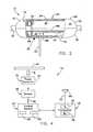
- FIG. 2is a side view in elevation of one embodiment of a sensing platform with a portion of the housing broken away to reveal the internal subsystems and components;
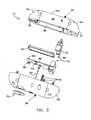
- FIG. 3is an exploded perspective view of the sensing platform illustrated in FIG. 2 ;
- FIG. 4is a schematic block diagram of the sensing platform illustrated in FIGS. 2 and 3 ;
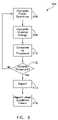
- FIG. 5is a schematic block diagram of a data processing routine utilized by a control system.
- FIG. 6is a schematic block diagram of an analysis routine.
- FIG. 1One embodiment of a monitoring system 10 is shown in FIG. 1 as it may be used to monitor a portion, or even substantially the entirety, of a transmission system 12 .
- the transmission system 12may comprise an electrical power transmission system 38 , although the invention may be used with other types of transmission systems as well.
- the monitoring system 10may comprise a plurality of individual sensing platforms 14 provided at various locations 16 along the transmission system 12 .
- Monitoring system 10may also comprise at least one endpoint receiver 18 . Endpoint receiver 18 may be positioned so that it receives information 20 transmitted by at least one of the plurality of sensing platforms 14 .
- endpoint receiver 18may be operatively associated with a user interface system 22 , such as, for example, a personal computer, to allow a user (not shown) to interpret and/or act on the information 20 received by endpoint receiver 18 .
- user interface system 22may also allow the user to transmit information or programming instructions to the various sensing platforms 14 .
- each sensing platform 14may be identical to the others (although this need not be the case), and may comprise a chassis or housing 24 sized to receive the various components and subsystems comprising the individual sensing platform 14 .
- the sensing platform 14may comprise at least one sensor 26 , a control system or processor 28 , and a transmitter 30 .
- the sensing platform 14also may be provided with a receiver 32 , in which case the combination of the transmitter 30 and receiver 32 may be referred to herein in the alternative as a transceiver 34 .
- the one or more sensors 26 comprising the sensing platform 14may be used to sense one or more conditions of the transmission system 12 and/or one or more conditions of an environment around the transmission system 12 .
- the control system or processor 28is operatively associated with the sensor(s) 26 and is also responsive to output signal(s) 36 produced by the sensor(s) 26 that relates to the sensed condition(s).
- the control system 28produces information 20 that relates to or is derived from the sensed condition.
- the transmitter 30is then used to transmit the information 20 produced by the control system 28 .
- the sensing platform 14may also be provided with a power conversion system 72 .
- Power conversion system 72extracts energy from the transmission system 12 ( FIG. 1 ) and converts it into a form useable by the sensing platform 14 .
- the transmission system 12comprises an electrical power transmission system 38 (see FIG. 1 )
- the power conversion system 72may comprise an inductive power converter 74 .
- inductive power converter 74may comprise a wire coil 76 positioned so that it is within an alternating magnetic field (shown schematically at “B” in FIG. 4 ) surrounding an electrical conductor 40 of the electrical power transmission system 38 .
- the alternating magnetic field Binduces an alternating electric current in wire coil 76 which may then be rectified and/or regulated by the inductive power converter 74 so that it is useable by the sensing platform 14 .
- each sensing platform 14monitors at least one condition of the transmission system 12 , such as, for example, vibrations detected in the transmission system 12 due to an event 55 occurring on or nearby support tower 42 . See FIG. 1 .
- each sensing platform 14may monitor at least one condition of an environment around the transmission system 12 , such as, for example, an ambient temperature or light in the infrared wavelength range that may be emitted by various objects or persons in the environment around the transmission system 12 .
- the control system 28 of each sensing platform 14may be configured to evaluate or analyze the output signals 36 produced by the sensor or sensors 26 to produce information 20 .
- the control system 28analyzes the output signal(s) 36 from the sensor(s) 26 to determine whether the sensed condition is a normal condition or an anomalous condition. If the sensed condition is determined to be an anomalous condition, the control system 28 may operate the transmitter 30 of the sensing platform 14 to transmit information 20 . The transmitted information 20 is ultimately received by the endpoint receiver 18 ( FIG. 1 ). If the sensed condition is determined to be a normal condition, then no information need be sent, although it could be.
- each sensing platform 14may be provided with a transceiver 34 (e.g., a transmitter 30 and a receiver 32 ). Consequently, in an embodiment wherein the monitoring system 10 comprises a plurality of sensing platforms 14 having such transceivers 34 , signals transmitted by one sensing platform 14 may be received by one or more nearby sensing platforms 14 . The nearby sensing platform(s) 14 may then re-transmit the signal, see FIG. 1 . In this manner, the transmitted signal may be relayed by various ones of the sensing platforms 14 comprising the monitoring system 10 until the signal is ultimately received by the endpoint receiver 18 .
- a transceiver 34e.g., a transmitter 30 and a receiver 32
- Additional redundancymay be realized by providing the monitoring system 10 with two or more endpoint receivers 18 located at different positions along the transmission system 12 (not depicted). If, for some reason, the signal from a sensing platform 14 fails to be relayed by nearby sensing platforms 14 along one direction, (thus fails to reach a first endpoint receiver 18 ), the signal from sensing platform 14 relayed by nearby sensing platforms 14 in the other direction may be received by a second endpoint receiver 18 located at the different position. Of course, the provision of additional endpoint receivers 18 at various points along the transmission system 12 may provide additional measures of redundancy.
- the endpoint receiver 18may be presented in human-readable form, thereby allowing a user or system operator to interpret and/or act upon the information 20 , as the case may be.
- the endpoint receiver 18is operatively associated with a user interface system 22 for this purpose.
- the user interface system 22may present the received information 20 on a display system 78 . For example, if the information 20 relates to an anomalous condition (e.g., event 55 , FIG.
- the user interface system 22may provide an indication about the anomalous condition, what it may relate to (e.g., vibrations, temperature, or infrared signature), as well as the particular sensing platform(s) 14 that detected the anomalous condition. Additional information, data, and options may also be provided by user interface system 22 , as will be described in further detail herein.
- One advantage of the present inventionis that it may be used to monitor a transmission system 12 and to provide to an endpoint receiver 18 information 20 regarding one or more monitored conditions.
- the information 20 regarding the one or more monitored conditionsmay be evaluated by a user to make a determination about whether the integrity of the transmission system 12 is, or may soon be, compromised.
- a usermay utilize the information 20 about the monitored condition or conditions for purposes other than evaluating the integrity and security of the transmission system 12 .
- the information 20 provided by one or more of the sensing platforms 14may be utilized to derive information about the passage of persons or vehicles within sensing range of one or more of the individual sensing platforms 14 . Still other purposes and variations are possible, as would become apparent to persons having ordinary skill in the art after having become familiar with the teachings provided herein. Consequently, the methods, apparatus, and systems shown and described herein should not be regarded as limited to any particular purpose.
- the power conversion system 72which may be provided in each of the sensing platforms 14 .
- deriving from the transmission system 12 the energy required to operate the individual sensing platforms 14dispenses with the need to provide each individual sensing platform 14 with a separate power supply (e.g., a storage battery) capable of operating the sensing platform 14 .
- the power conversion system 72will allow the individual sensing platforms 14 to be readily located at even remote areas along the transmission system 12 without concern for providing a separate power source (e.g., a storage battery) to the sensing platforms 14 .
- the arrangementalso dispenses with the need to periodically service or replace the storage battery.
- a plurality of individual sensing platforms 14may be mounted at various locations 16 (see FIG. 1 ) along the transmission system 12 , thereby allowing extended portions, or even substantially the entirety, of the transmission system 12 to be monitored. Alternatively, only selected portions of the transmission system 12 may be monitored with the monitoring system 10 .
- the ability of the sensing platforms 14 to relay transmissions from adjacent sensing platforms 14allows low-power transmitters (e.g., transceivers) to be utilized.
- the signal relaying capabilityalso dispenses with the need to provide more than one endpoint receiver 18 , although multiple endpoint receivers 18 may be provided if so desired.
- the signals transmitted by the individual sensing platforms 14are typically of sufficient strength so that they may be received by more than one adjacent sensing platform 14 . Consequently, the signal may continue to be relayed even though one of the sensing platforms 14 receiving the transmitted signal may be unable to re-transmit (e.g., relay) the signal.
- the various individual sensing platforms 14 and monitoring system 10are not limited to use with electrical power transmission systems 38 , but could also be used with other types of transmission systems, such as, for example, telecommunications (e.g., telephone) systems, oil pipelines, gas pipelines, water pipelines, or other types of systems for moving or transmitting resources, such as electricity or materials, from one location to another.
- telecommunicationse.g., telephone
- oil pipelinese.g., gas pipelines
- water pipelinese.g., water pipelines
- the transmission system 12may comprise an electrical power transmission system 38 having a plurality of electrical conductors 40 supported by a plurality of support towers 42 .
- the monitoring system 10may be used with other types of transmission systems, such as, for example, telecommunications (e.g., telephone) systems, oil pipelines, gas pipelines, water pipelines, or other types of systems for moving or transmitting resources, such as electricity or materials, from one location to another. Consequently, the present invention should not be regarded as limited to use with any particular type of transmission system 12 .
- the monitoring system 10may comprise at least one, and typically a plurality of sensing platforms 14 provided at various locations 16 along the transmission system 12 .
- the various sensing platforms 14are mounted to one of the electrical conductors 40 at locations 16 nearby the support towers 42 . So positioning the various sensing platforms 14 nearby the support towers 42 will allow the sensing platforms 14 to more easily monitor conditions (e.g., event 55 ) on and around the support towers 42 . Of course, other positioning arrangements may be utilized depending on the particular type of transmission system 12 and the conditions to be monitored.
- the various ones of the sensing platforms 14 comprising the monitoring system 10may be identical to one another, although this need not be the case.
- various ones of the sensing platforms 14 comprising the monitoring system 10may be provided with different sensing capabilities depending on where they are to be located on the transmission system 12 and depending on the particular condition(s) that is/are desired to be sensed.
- various ones of the sensing platforms 14may include or lack certain other components (e.g., a transmitter 30 or receiver 32 ), again depending on the particular application, as well as the desired sensing and monitoring capabilities of the monitoring system 10 . Consequently, the present invention should not be regarded as limited to arrangements wherein the sensing platforms 14 are identical to one another.
- a sensing platform 14may comprise a housing 24 sized to receive the various components and subsystems of the sensing platform 14 .
- housing 24may comprise a two-piece or split housing 24 having a first half 44 and a second half 46 .
- the first and second halves 44 and 46 of split housing 24may define one or more respective cavities (e.g., cavities 48 and 50 ) therein sized to receive the various subsystems and components of the sensing platform 14 .
- the first and second halves 44 and 46may be releasably secured to one another (e.g., via a plurality of fasteners 52 ) to allow the first and second halves 44 and 46 to be readily separated, thereby providing easy access to the various systems and components housed therein.
- the two-piece arrangement of housing 24also allows the sensing platform 14 to be readily secured to the electrical conductor 40 of the electrical power transmission system 38 .
- the housing 24may also need to be provided with certain other features and attributes to allow it to function well in the intended application (e.g., with the particular type of transmission system 12 involved) and in the expected environment.
- the housing 24should be configured to minimize the likelihood of corona discharge at the voltages expected in the electrical power transmission system 38 . Protection against corona discharge is particularly important wherein the voltages involved are in the tens of kilovolt range or higher.
- One shape that will minimize corona dischargecomprises a generally cylindrically-shaped main body portion 54 having a pair of generally hemispherically-shaped end portions 56 , 57 , as best seen in FIGS. 2 and 3 .
- other shapesare possible, as would become apparent to persons having ordinary skill in the art after having become familiar with the teachings provided herein.
- any fasteners 52 used to fasten together the two halves 44 and 46 of housing 24should be recessed within the halves 44 and 46 so that the fasteners 52 do not protrude beyond the exterior surface 58 of housing 24 , as best seen in FIG. 2 .
- housing 24should also be made from an electrically conductive material (e.g., aluminum) so that housing 24 will remain at the same electrical potential as the electrical conductor 40 .
- suitable precautionsalso should be taken to prevent the housing 24 from carrying electrical current that would normally be carried by electrical conductor 40 .
- One suitable precautionis to provide an insulator 60 ( FIG. 3 ) between one of the end portions (e.g., end portion 56 ) of housing 24 and the electrical conductor 40 , while allowing the other end portion (e.g., end portion 57 ) of housing 24 to remain in electrical contact with electrical conductor 40 .
- the sensing platform 14may be provided with a variety of subsystems and components in order to carry out the functional and operational aspects of the sensing platform 14 .
- the various subsystems and componentsare provided on a single printed wiring board 68 sized to be received within housing 24 .
- Printed wiring board 68may be housed within the second or lower half 46 of housing 24 .
- a cover plate 90may be used to secure the printed wiring board 68 within the second half 46 and to insulate it from electrical conductor 40 , as best seen in FIGS. 2 and 3 .
- other arrangementsare possible, as would become apparent to persons having ordinary skill in the art after having become familiar with the teachings provided herein.
- Sensing platform 14may be provided one or more sensors 26 suitable for sensing any of a wide range of conditions of the transmission system 12 ( FIG. 1 ).
- sensor 26may be used to sense at least one condition of the transmission system 12 or may be used to sense at least one condition of an environment surrounding the transmission system 12 .
- Exemplary sensors that may be utilized in sensing platform 14include, but are not limited to, motion sensors (e.g., accelerometers), acoustic sensors, temperature sensors, and optical sensors (e.g., detectors and cameras).
- each sensing platform 14is provided with three sensors 26 : A two-axis accelerometer 62 , an infrared detector 64 , and a temperature sensor 66 , see FIG. 3 .
- the various sensors 26may be mounted to printed wiring board 68 .
- Two-axis accelerometer 62detects or senses movement (e.g., acceleration) along two different axes, which may be perpendicular to one another, although this is not required.
- movemente.g., acceleration
- the two-axis accelerometer 62should not be regarded as limited to detecting accelerations along two axes, but could instead comprise a single-axis accelerometer, a three-axis accelerometer, or any combination of single- or multi-axis accelerometers, as may be required to sense or detect the desired motion.
- two-axis accelerometer 62may be used to detect motion (e.g., vibrations) of the transmission system 12 , such as, for example, vibrations caused by event 55 occurring on or near support tower 42 , see FIG. 1 .
- Two-axis accelerometer 62may comprise any of a wide range of accelerometers now known in the art or that may be developed in the future that arc, or would be, suitable for the intended application. Consequently, the present invention should not be regarded as limited to any particular type of accelerometer.
- the two-axis accelerometer 62comprises an “accelerometer on a chip,” such as, for example product No. ADXL203, available from Analog Devices, Inc., of Norwood, Mass.
- the two-axis accelerometer 62may be mounted to the printed wiring board 68 .
- the infrared detector 64may be used to detect light in the infrared portion of the electromagnetic spectrum. Consequently, the infrared detector 64 may be used to detect objects (e.g., persons, animals, or vehicles) or events that emit infrared signatures.
- infrared detector 64comprises a multi-element sensor having a field of view sufficient to encompass the desired area to be sensed.
- the monitoring systemis utilized to monitor an electrical power transmission system 38
- Infrared detector 64may comprise any of a wide variety of infrared detectors that are known in the art or that may be developed in the future. Consequently, the present invention should not be regarded as limited to use with any particular type of infrared detector 64 .
- infrared detector 64may comprise an infrared detector available from PerkinElmer Optoelectronics, Inc., of Fremont, Calif. as product no. LHi1128.
- infrared detector 64may be mounted on printed wiring board 68 .
- a suitable lens 70may be mounted to housing 24 , as best seen in FIGS. 2 and 3 .
- other arrangementsare possible, as would become apparent to persons having ordinary skill in the art after having become familiar with the teachings provided herein.
- Sensing platform 14may also be provided with a temperature sensor 66 for monitoring an ambient temperature, which may be desirable in certain applications.
- temperature sensor 66may comprise a temperature sensor available from Microchip Technology Inc., of Chandler, Ariz. as product No. TC1047. Temperature sensor 66 may be mounted on printed wiring board 68 , although other arrangements are possible.
- the sensing platform 14may also comprise a control system or processor 28 operatively associated with the sensor or sensors 26 .
- Control system 28receives output signals 36 from each of the sensors 26 and produces information 20 relating to the one or more conditions sensed by the sensors 26 .
- Control system or processor 28may also be mounted to printed wiring board 68 and may comprise one or more general-purpose digital signal processors or “computers on a chip” of the type well known in the art and readily commercially available.
- the control system 28comprises two digital signal processors 80 and 82 that operate together to perform the functions and operations of control system 28 .
- the first digital signal processor 80operates the various sensors 26 , receives the various output signals 36 produced by the sensors 26 , and analyzes the output signals 36 to produce information 20 about the sensed conditions.
- the second digital signal processor 82receives the information 20 from the first digital signal processor 80 and operates the transceiver 34 .
- the digital signal processors 80 and 82may comprise any of a wide range of processors now known in the art or that may be developed in the future that are, or would be, suitable for the particular application. Consequently, the present invention should not be regarded as limited to any particular type of processor, or even combinations of processors. However, by way of example, in one embodiment, both digital signal processors 80 and 82 may comprise processors, available from Microchip Technology Inc., of Chandler, Ariz., as product No. PIC30F6012.
- each sensing platform 14with a transceiver 34 comprising a transmitter 30 and a receiver 32 .
- a receiver 32need not be provided, depending on the functionality that is to be provided by sensing platform 14 .
- the transceiver 34may be connected to a suitable antenna 84 to allow signals (e.g., information 20 ) to be transmitted by and received from the transceiver 34 as radio-frequency signals, see FIG. 1 .
- Transceiver 34may comprise any of a wide range of transceivers known in the art and that would be suitable for the intended application. Consequently, transceiver 34 should not be regarded as limited to any particular type of transceiver. However, by way of example, in one embodiment, transceiver 34 comprises product No. MICRF505 transceiver available from Micrel, Inc., of San Jose, Calif.
- the information 20could be transmitted along one or more components (e.g., electrical conductors 40 ) of the transmission system 12 itself.
- the information 20need not be transmitted by radio, but could instead be transmitted by other means (e.g., by light), as would become apparent to persons having ordinary skill in the art after having become familiar with the teachings provided herein. Consequently, the present invention should not be regarded as limited to the particular types of transmitters (e.g., radio-frequency transmitters) shown and described herein.
- each sensing platform 14may be provided with a power conversion system 72 .
- Power conversion system 72allows each sensing platform 14 to be operated by energy derived from the transmission system 12 .
- Power conversion system 72thereby allows the sensing platform 14 to be operated without the need to provide a separate power source, such as a storage battery.
- Power conversion system 72may comprise any of a wide range of systems suitable for deriving energy from the particular type of transmission system 12 . Consequently, the present invention should not be regarded as limited to any particular type of power conversion system.
- the transmission system 12comprises an electrical power transmission system 38
- power conversion system 72comprises an inductive power converter 74 .
- inductive power converter 74may comprise a wire coil 76 ( FIG. 2 ) positioned so that it is contained within an alternating magnetic field B produced by the electrical power transmission system 38 .
- wire coil 76may be wrapped around a portion of a two-piece or split core element 86 that is configured to surround electrical conductor 40 when the sensing platform 14 is mounted thereto, as best seen in FIGS. 2 and 3 .
- the alternating magnetic field B surrounding the electrical conductor 40will induce an alternating current flow in wire coil 76 .
- Inductive power converter 74may also be provided with suitable rectification and regulation circuitry (not shown) to convert the alternating current in wire coil 76 into a regulated, direct current suitable for use by the various components and systems comprising the sensing platform 14 .
- inductive power converter 74it will be advantageous to design inductive power converter 74 so that it will be substantially vibration-free during operation, as vibrations produced by inductive power converter 74 would be detected by any accelerometers or motion sensors provided on the sensing platform 14 . Vibration-free operation can be enhanced by ensuring that the split core element 86 remains linear (e.g., does not become magnetically saturated) during operation. Inductive power converter 74 may also be provided with one or more large capacitors or “super” capacitors (not shown) to provide electrical power to the sensing platform 14 for some period of time (e.g., minutes) if the current flow in the electrical conductor 40 is lost. Therefore, sensing platform 14 will be able to transmit information about the anomalous condition (e.g., power loss in the electrical conductor 40 ). Alternatively, other back-up power supplies (e.g., storage batteries) could be utilized.
- other back-up power suppliese.g., storage batteries
- endpoint receiver 18may comprise a receiver (not shown) suitable for receiving information 20 transmitted by one or more sensing platforms 14 .
- Endpoint receiver 18may also be provided with a transmitter (also not shown) for transmitting data to the various sensing platforms 14 .
- the receiver and transmitterare combined into a transceiver that may be identical to the transceiver utilized in the sensing platforms 14 , thus will not be described in further detail herein.
- endpoint receiver 18may be configured to operate in conjunction with user interface system 22 . Consequently, endpoint receiver 18 need not be provided with a separate user interface system, although a user interface could be provided directly on endpoint receiver 18 . However, endpoint receiver 18 may be provided with a suitable data interface system (also not shown) suitable for allowing endpoint receiver 18 to communicate with user interface system 22 .
- user interface system 22comprises a general purpose programmable computer (e.g., a personal computer)
- the data interface system provided on the endpoint receiver 18may comprise any of a wide range of data interface systems or communication links 77 suitable for communicating with the particular type of computer comprising the user interface system 22 . Consequently, the present invention should not be regarded as limited to any particular type of data interface system.
- the data interface systemmay comprise an RS-232 data interface system.
- communication link 77may comprise an existing communication system (e.g., telephone lines, microwave relay stations, fiber-optic lines, etc.) located with or nearby the transmission system 12 .
- an existing communication systeme.g., telephone lines, microwave relay stations, fiber-optic lines, etc.
- informationmay be transmitted between endpoint receiver 18 and user interface system 22 via an existing communication system.
- Such an arrangementmay allow one or more endpoint receivers 18 to be conveniently mounted on one or more support towers 42 ( FIG. 1 ) and tied-in to the existing communication system (e.g., telephone line), thereby allowing the user interface system 22 to be provided at any convenient location.
- user interface system 22may comprise any of a wide range of systems and devices known in the art or that may be developed in the future that are or would be suitable for allowing the desired degree of user interface with monitoring system 10 .
- the user interface system 22may comprise a general purpose programmable computer system, such as a personal computer having a display system 78 and a keyboard 88 .
- Information 20 received by endpoint receiver 18may be displayed on the display system 78 of user interface system 22 .
- the keyboard 88may be utilized to manipulate the information 20 and/or change the layout of the information 20 provided on display system 78 .
- user interface system 22may be used to send data and/or programming information or modifications back to the sensing platforms 14 via the transceiver provided in the endpoint receiver 18 .
- the monitoring system 10may be operated as follows to sense at least one condition of the transmission system 12 .
- the various sensing platforms 14may be used to sense one or more conditions of the transmission system 12 , ranging from, for example, vibrations of the transmission system 12 sensed by the two-axis accelerometer 62 , infrared light emitted by objects or persons within the sensing area of infrared sensor detector 64 , and/or the ambient temperature, as sensed by the temperature sensor 66 ( FIG. 3 ).
- the output signal(s) 36 from the sensor or sensors 26are received by the control system or processor 28 ( FIG. 4 ). While the control system or processor 28 may simply pass-on the signals to the transmitter 30 ( FIG.
- control system or processor 28may first evaluate or analyze the output signals 36 in order to determine whether the sensed conditions are normal or anomalous. In this way, only information 20 that relates to an anomalous condition need be transmitted.
- a data processing routine 92 that may be utilized by the control system 28 ( FIG. 4 ) to evaluate the output signals 36is illustrated in FIG. 5 .
- the output signal 36 from the sensors 26 ( FIG. 4 )may be pre-filtered at step 94 in order to remove unwanted or undesirable components (e.g., 60 Hz noise and harmonics thereof) from the output signals 36 in order to simplify subsequent processing and analysis.
- the pre-filtering process 94may involve the use of one or more analog or digital filters, such as high-pass, low-pass, or band-pass filters.
- the particular characteristics of the pre-filter 94may vary depending on the particular types of output signals 36 produced by the various sensors 26 and would be easily selected by persons having ordinary skill in the art after having become familiar with the teachings provided herein and after considering the particular sensors 26 to be utilized and noise components to be removed. Consequently, the particular types of filters that may be utilized in the pre-filtering process will not be described in further detail herein.
- filtered signalsmay then be digitized at step 96 .
- digitizationneed not be performed if the signals already comprise digital, as opposed to analog, signals.
- the digitized signalsmay then be processed by any of a wide variety of digital signal processing techniques in order to produce signals that may be more conducive to the subsequent analysis process 104 .
- the particular digital signal processing techniqueswill depend on the type of analysis to be performed, e.g., to determine whether the output signals 36 are indicative of a normal condition or an anomalous condition, as well as on the particular nature of the output signals 36 , e.g., whether the output signals 36 were generated by an accelerometer (e.g., a two-axis accelerometer 62 ), an infrared sensor (e.g., infrared detector 64 ), or by a temperature sensor (e.g., temperature sensor 66 ), see FIG. 3 .
- an output signal from a temperature sensore.g., temperature sensor 66
- an output signal from a temperature sensorwill require much less processing than an output signal generated by an accelerometer (e.g.
- a subsequent digital signal processing techniquemay comprise a Fast-Fourier Transform (FFT) step 98 , in which the output signals are converted from the time domain into the frequency domain.
- FFTFast-Fourier Transform
- a subsequent filtering step 102may then be conducted to filter or remove unwanted components from the processed signal.
- the output signals 36may then be analyzed at step 104 .
- the analysis process 104may be performed to determine whether the output signal 36 produced by the sensor 26 is indicative of a normal condition or an anomalous condition.
- One way to make such a determinationis to compare the output signal 36 with a threshold value or values associated with a normal condition. If the output signal 36 is outside the threshold value or values, then the sensed condition is regarded as anomalous.
- the particular threshold value or values that may be utilizedwill depend on the particular sensor output signal to be analyzed, as well as on the particular type of transmission system 12 and environment. In certain circumstances, it will be sufficient to simply compare the processed output signal with the corresponding threshold value or values established for the particular sensor. However, in other cases, it may be necessary to additionally process the data before making the comparison.
- a better determination as to whether data from a motion sensore.g., two-axis accelerometers 62 ) are indicative of a normal condition or an anomalous condition may require the power spectrum of the signal to be computed, as illustrated in step 106 .
- the impulse energy of the power spectrummay then be computed at step 108 .
- the computed impulse energymay then be compared with a corresponding threshold value or values at step 110 .
- the threshold value or valuesmay be developed from testing associated with the particular type of transmission system 12 , as well as on the particular type of sensor.
- suitable threshold valuesmay be determined by measuring accelerations detected by one or more sensing platforms 14 mounted on the electrical conductors 40 in response to simulated events. The resulting responses may then be used to establish corresponding threshold values.
- accelerationsthemselves could be analyzed (e.g., as they are detected in the time domain), it will generally be easier to perform the analysis if the acceleration data is converted into the frequency domain (e.g., via Fast-Fourier Transform of process 98 , FIG. 5 ).
- the power spectrum and impulse energycan be calculated (at steps 106 and 108 , respectively) by known techniques. In this way, threshold values associated with potentially threatening activities can be determined and programmed into the control system 28 ( FIG. 4 ).
- a reporte.g., transmit information 20
- the information 20 provided in the report (e.g., at step 114 ) transmitted by the sensing platform 14may comprise any of a wide range of information.
- information 20may contain processed data (e.g., the calculated impulse energy), as well as unprocessed or raw data produced by the sensors 26 ( FIG. 4 ).
- the information 20may also include data from other sensors 26 even if the data produced thereby was determined to be indicative of a normal condition.
- the information 20may also contain the identity and/or location of the sensing platform 14 that detected the anomalous condition.
- information 20may comprise any of a wide variety of information that may be useful to a system operator if an anomalous condition is detected.
- the information 20 transmitted by the sensing platform 14 that detected the anomalous conditionmay be relayed by one or more other sensing platforms 14 provided on the transmission system 12 before being received by endpoint receiver 18 , as already described.
- Endpoint receiver 18may operate in conjunction with user interface system 22 in order to provide the information 20 in any desired form.
- user interface system 22may be programmed to provide a visual and/or aural alarm.
- the identification and location of the particular sensing platform or platforms 14 that detected the anomalous conditionmay also be provided, along with processed data and/or raw data. Any other information may be provided that would be deemed useful to a system operator in evaluating the seriousness of the situation.
- the sensing platform 14is provided with an optical sensor (e.g., a camera), image data from the camera may be provided to allow a user to perhaps determine the cause of the anomalous condition.
- an optical sensore.g., a camera
- the user interface system 22 and endpoint receiver 18may also be used to transmit information to the various sensing platforms 14 .
- the userin response to receiving information 20 indicative of the detection of an anomalous condition, the user may instruct the user interface system 22 to send a signal to the sensing platform 14 requesting additional data relating to the detected condition.
- the user interface system 22could also be used to re-program one or more of the other sensing platforms 14 to, for example, change the threshold levels. Such re-programming could allow the anomalous condition to be determined with more certainty by determining whether other sensing platforms 14 detected similar data.
- re-programming of the sensing platforms 14need not be done upon the detection of an anomalous condition, but could be done at any time.
- Many other variationsare possible, as would become apparent to persons having ordinary skill in the art after having become familiar with the teachings provided herein. Consequently, the present invention should not be regarded as limited to the particular programming sequences and operational scenarios shown and described herein.
Landscapes
- Engineering & Computer Science (AREA)
- Computer Networks & Wireless Communication (AREA)
- Signal Processing (AREA)
- Alarm Systems (AREA)
- Arrangements For Transmission Of Measured Signals (AREA)
- Selective Calling Equipment (AREA)
Abstract
Description
Claims (17)
Priority Applications (4)
| Application Number | Priority Date | Filing Date | Title |
|---|---|---|---|
| US11/425,287US7786894B2 (en) | 2006-06-20 | 2006-06-20 | Methods, apparatus, and systems for monitoring transmission systems |
| PCT/US2007/069419WO2007149668A2 (en) | 2006-06-20 | 2007-05-22 | Methods, apparatus, and systems for monitoring transmission systems |
| US12/572,141US8941491B2 (en) | 2006-06-20 | 2009-10-01 | Methods, apparatus, and systems for monitoring transmission systems |
| US14/605,709US9398352B2 (en) | 2006-06-20 | 2015-01-26 | Methods, apparatus, and systems for monitoring transmission systems |
Applications Claiming Priority (1)
| Application Number | Priority Date | Filing Date | Title |
|---|---|---|---|
| US11/425,287US7786894B2 (en) | 2006-06-20 | 2006-06-20 | Methods, apparatus, and systems for monitoring transmission systems |
Related Child Applications (1)
| Application Number | Title | Priority Date | Filing Date |
|---|---|---|---|
| US12/572,141DivisionUS8941491B2 (en) | 2006-06-20 | 2009-10-01 | Methods, apparatus, and systems for monitoring transmission systems |
Publications (2)
| Publication Number | Publication Date |
|---|---|
| US20080024321A1 US20080024321A1 (en) | 2008-01-31 |
| US7786894B2true US7786894B2 (en) | 2010-08-31 |
Family
ID=38834207
Family Applications (3)
| Application Number | Title | Priority Date | Filing Date |
|---|---|---|---|
| US11/425,287Active2027-02-15US7786894B2 (en) | 2006-06-20 | 2006-06-20 | Methods, apparatus, and systems for monitoring transmission systems |
| US12/572,141ActiveUS8941491B2 (en) | 2006-06-20 | 2009-10-01 | Methods, apparatus, and systems for monitoring transmission systems |
| US14/605,709Active2026-07-28US9398352B2 (en) | 2006-06-20 | 2015-01-26 | Methods, apparatus, and systems for monitoring transmission systems |
Family Applications After (2)
| Application Number | Title | Priority Date | Filing Date |
|---|---|---|---|
| US12/572,141ActiveUS8941491B2 (en) | 2006-06-20 | 2009-10-01 | Methods, apparatus, and systems for monitoring transmission systems |
| US14/605,709Active2026-07-28US9398352B2 (en) | 2006-06-20 | 2015-01-26 | Methods, apparatus, and systems for monitoring transmission systems |
Country Status (2)
| Country | Link |
|---|---|
| US (3) | US7786894B2 (en) |
| WO (1) | WO2007149668A2 (en) |
Cited By (180)
| Publication number | Priority date | Publication date | Assignee | Title |
|---|---|---|---|---|
| US20100033345A1 (en)* | 2006-06-20 | 2010-02-11 | Battelle Energy Alliance, Llc | Methods, apparatus, and systems for monitoring transmission systems |
| US20100114392A1 (en)* | 2008-11-06 | 2010-05-06 | Mark Lancaster | Real-Time Power Line Rating |
| US20100151735A1 (en)* | 2008-12-17 | 2010-06-17 | Fci Americas Technology, Inc. | Data collecting connection |
| US8160825B1 (en)* | 2011-10-26 | 2012-04-17 | Roe Jr George Samuel | Process for remote grounding, transmission sensing, and temperature monitoring device |
| US8738318B2 (en) | 2010-08-02 | 2014-05-27 | Lindsey Manufacturing Company | Dynamic electric power line monitoring system |
| US20150122047A1 (en)* | 2013-11-05 | 2015-05-07 | Honda Motor Co., Ltd. | Cable track monitoring system and method |
| US9042812B1 (en) | 2013-11-06 | 2015-05-26 | At&T Intellectual Property I, Lp | Surface-wave communications and methods thereof |
| US9113347B2 (en) | 2012-12-05 | 2015-08-18 | At&T Intellectual Property I, Lp | Backhaul link for distributed antenna system |
| US9209902B2 (en) | 2013-12-10 | 2015-12-08 | At&T Intellectual Property I, L.P. | Quasi-optical coupler |
| US9312919B1 (en) | 2014-10-21 | 2016-04-12 | At&T Intellectual Property I, Lp | Transmission device with impairment compensation and methods for use therewith |
| US9461706B1 (en) | 2015-07-31 | 2016-10-04 | At&T Intellectual Property I, Lp | Method and apparatus for exchanging communication signals |
| US9490869B1 (en) | 2015-05-14 | 2016-11-08 | At&T Intellectual Property I, L.P. | Transmission medium having multiple cores and methods for use therewith |
| US9503189B2 (en) | 2014-10-10 | 2016-11-22 | At&T Intellectual Property I, L.P. | Method and apparatus for arranging communication sessions in a communication system |
| US9509415B1 (en) | 2015-06-25 | 2016-11-29 | At&T Intellectual Property I, L.P. | Methods and apparatus for inducing a fundamental wave mode on a transmission medium |
| US9519014B2 (en) | 2012-12-06 | 2016-12-13 | Dynamic Engineers, Inc. | Systems and methods for calculating power transmission line capacity |
| US9520945B2 (en) | 2014-10-21 | 2016-12-13 | At&T Intellectual Property I, L.P. | Apparatus for providing communication services and methods thereof |
| US9525210B2 (en) | 2014-10-21 | 2016-12-20 | At&T Intellectual Property I, L.P. | Guided-wave transmission device with non-fundamental mode propagation and methods for use therewith |
| US9525524B2 (en) | 2013-05-31 | 2016-12-20 | At&T Intellectual Property I, L.P. | Remote distributed antenna system |
| US9531427B2 (en) | 2014-11-20 | 2016-12-27 | At&T Intellectual Property I, L.P. | Transmission device with mode division multiplexing and methods for use therewith |
| US9564947B2 (en) | 2014-10-21 | 2017-02-07 | At&T Intellectual Property I, L.P. | Guided-wave transmission device with diversity and methods for use therewith |
| US20170038406A1 (en)* | 2013-03-14 | 2017-02-09 | Hubbell Incorporated | Apparatuses, Systems and Methods for Determining Effective Wind Speed |
| US9577306B2 (en) | 2014-10-21 | 2017-02-21 | At&T Intellectual Property I, L.P. | Guided-wave transmission device and methods for use therewith |
| US9608740B2 (en) | 2015-07-15 | 2017-03-28 | At&T Intellectual Property I, L.P. | Method and apparatus for launching a wave mode that mitigates interference |
| US9608692B2 (en) | 2015-06-11 | 2017-03-28 | At&T Intellectual Property I, L.P. | Repeater and methods for use therewith |
| US9615269B2 (en) | 2014-10-02 | 2017-04-04 | At&T Intellectual Property I, L.P. | Method and apparatus that provides fault tolerance in a communication network |
| US9628854B2 (en) | 2014-09-29 | 2017-04-18 | At&T Intellectual Property I, L.P. | Method and apparatus for distributing content in a communication network |
| US9628116B2 (en) | 2015-07-14 | 2017-04-18 | At&T Intellectual Property I, L.P. | Apparatus and methods for transmitting wireless signals |
| US9640850B2 (en) | 2015-06-25 | 2017-05-02 | At&T Intellectual Property I, L.P. | Methods and apparatus for inducing a non-fundamental wave mode on a transmission medium |
| US9653770B2 (en) | 2014-10-21 | 2017-05-16 | At&T Intellectual Property I, L.P. | Guided wave coupler, coupling module and methods for use therewith |
| US9654173B2 (en) | 2014-11-20 | 2017-05-16 | At&T Intellectual Property I, L.P. | Apparatus for powering a communication device and methods thereof |
| US9667317B2 (en) | 2015-06-15 | 2017-05-30 | At&T Intellectual Property I, L.P. | Method and apparatus for providing security using network traffic adjustments |
| US9680670B2 (en) | 2014-11-20 | 2017-06-13 | At&T Intellectual Property I, L.P. | Transmission device with channel equalization and control and methods for use therewith |
| US9685992B2 (en) | 2014-10-03 | 2017-06-20 | At&T Intellectual Property I, L.P. | Circuit panel network and methods thereof |
| US9692101B2 (en) | 2014-08-26 | 2017-06-27 | At&T Intellectual Property I, L.P. | Guided wave couplers for coupling electromagnetic waves between a waveguide surface and a surface of a wire |
| US9697724B2 (en) | 2010-09-22 | 2017-07-04 | Hubbell Incorporated | Transmission line measuring device and method for connectivity and monitoring |
| US9705561B2 (en) | 2015-04-24 | 2017-07-11 | At&T Intellectual Property I, L.P. | Directional coupling device and methods for use therewith |
| US9705571B2 (en) | 2015-09-16 | 2017-07-11 | At&T Intellectual Property I, L.P. | Method and apparatus for use with a radio distributed antenna system |
| US9722318B2 (en) | 2015-07-14 | 2017-08-01 | At&T Intellectual Property I, L.P. | Method and apparatus for coupling an antenna to a device |
| US9729197B2 (en) | 2015-10-01 | 2017-08-08 | At&T Intellectual Property I, L.P. | Method and apparatus for communicating network management traffic over a network |
| US9735833B2 (en) | 2015-07-31 | 2017-08-15 | At&T Intellectual Property I, L.P. | Method and apparatus for communications management in a neighborhood network |
| US9742462B2 (en) | 2014-12-04 | 2017-08-22 | At&T Intellectual Property I, L.P. | Transmission medium and communication interfaces and methods for use therewith |
| US9749013B2 (en) | 2015-03-17 | 2017-08-29 | At&T Intellectual Property I, L.P. | Method and apparatus for reducing attenuation of electromagnetic waves guided by a transmission medium |
| US9749053B2 (en) | 2015-07-23 | 2017-08-29 | At&T Intellectual Property I, L.P. | Node device, repeater and methods for use therewith |
| US9748626B2 (en) | 2015-05-14 | 2017-08-29 | At&T Intellectual Property I, L.P. | Plurality of cables having different cross-sectional shapes which are bundled together to form a transmission medium |
| US9755697B2 (en) | 2014-09-15 | 2017-09-05 | At&T Intellectual Property I, L.P. | Method and apparatus for sensing a condition in a transmission medium of electromagnetic waves |
| US9762289B2 (en) | 2014-10-14 | 2017-09-12 | At&T Intellectual Property I, L.P. | Method and apparatus for transmitting or receiving signals in a transportation system |
| US9769020B2 (en) | 2014-10-21 | 2017-09-19 | At&T Intellectual Property I, L.P. | Method and apparatus for responding to events affecting communications in a communication network |
| US9769128B2 (en) | 2015-09-28 | 2017-09-19 | At&T Intellectual Property I, L.P. | Method and apparatus for encryption of communications over a network |
| US9780834B2 (en) | 2014-10-21 | 2017-10-03 | At&T Intellectual Property I, L.P. | Method and apparatus for transmitting electromagnetic waves |
| US9784766B2 (en) | 2013-03-12 | 2017-10-10 | Lindsey Manufacturing Company | Dynamic real time transmission line monitor and method of monitoring a transmission line using the same |
| US9793955B2 (en) | 2015-04-24 | 2017-10-17 | At&T Intellectual Property I, Lp | Passive electrical coupling device and methods for use therewith |
| US9793954B2 (en) | 2015-04-28 | 2017-10-17 | At&T Intellectual Property I, L.P. | Magnetic coupling device and methods for use therewith |
| US9793951B2 (en) | 2015-07-15 | 2017-10-17 | At&T Intellectual Property I, L.P. | Method and apparatus for launching a wave mode that mitigates interference |
| US9800327B2 (en) | 2014-11-20 | 2017-10-24 | At&T Intellectual Property I, L.P. | Apparatus for controlling operations of a communication device and methods thereof |
| US9820146B2 (en) | 2015-06-12 | 2017-11-14 | At&T Intellectual Property I, L.P. | Method and apparatus for authentication and identity management of communicating devices |
| US9838896B1 (en) | 2016-12-09 | 2017-12-05 | At&T Intellectual Property I, L.P. | Method and apparatus for assessing network coverage |
| US9836957B2 (en) | 2015-07-14 | 2017-12-05 | At&T Intellectual Property I, L.P. | Method and apparatus for communicating with premises equipment |
| US9847566B2 (en) | 2015-07-14 | 2017-12-19 | At&T Intellectual Property I, L.P. | Method and apparatus for adjusting a field of a signal to mitigate interference |
| US9847850B2 (en) | 2014-10-14 | 2017-12-19 | At&T Intellectual Property I, L.P. | Method and apparatus for adjusting a mode of communication in a communication network |
| US9853342B2 (en) | 2015-07-14 | 2017-12-26 | At&T Intellectual Property I, L.P. | Dielectric transmission medium connector and methods for use therewith |
| US9860075B1 (en) | 2016-08-26 | 2018-01-02 | At&T Intellectual Property I, L.P. | Method and communication node for broadband distribution |
| US9866309B2 (en) | 2015-06-03 | 2018-01-09 | At&T Intellectual Property I, Lp | Host node device and methods for use therewith |
| US9865911B2 (en) | 2015-06-25 | 2018-01-09 | At&T Intellectual Property I, L.P. | Waveguide system for slot radiating first electromagnetic waves that are combined into a non-fundamental wave mode second electromagnetic wave on a transmission medium |
| US9871282B2 (en) | 2015-05-14 | 2018-01-16 | At&T Intellectual Property I, L.P. | At least one transmission medium having a dielectric surface that is covered at least in part by a second dielectric |
| US9871283B2 (en) | 2015-07-23 | 2018-01-16 | At&T Intellectual Property I, Lp | Transmission medium having a dielectric core comprised of plural members connected by a ball and socket configuration |
| US9876264B2 (en) | 2015-10-02 | 2018-01-23 | At&T Intellectual Property I, Lp | Communication system, guided wave switch and methods for use therewith |
| US9876605B1 (en) | 2016-10-21 | 2018-01-23 | At&T Intellectual Property I, L.P. | Launcher and coupling system to support desired guided wave mode |
| US9876570B2 (en) | 2015-02-20 | 2018-01-23 | At&T Intellectual Property I, Lp | Guided-wave transmission device with non-fundamental mode propagation and methods for use therewith |
| US9882257B2 (en) | 2015-07-14 | 2018-01-30 | At&T Intellectual Property I, L.P. | Method and apparatus for launching a wave mode that mitigates interference |
| US9882277B2 (en) | 2015-10-02 | 2018-01-30 | At&T Intellectual Property I, Lp | Communication device and antenna assembly with actuated gimbal mount |
| US9893795B1 (en) | 2016-12-07 | 2018-02-13 | At&T Intellectual Property I, Lp | Method and repeater for broadband distribution |
| US9906269B2 (en) | 2014-09-17 | 2018-02-27 | At&T Intellectual Property I, L.P. | Monitoring and mitigating conditions in a communication network |
| US9904535B2 (en) | 2015-09-14 | 2018-02-27 | At&T Intellectual Property I, L.P. | Method and apparatus for distributing software |
| US9911020B1 (en) | 2016-12-08 | 2018-03-06 | At&T Intellectual Property I, L.P. | Method and apparatus for tracking via a radio frequency identification device |
| US9913139B2 (en) | 2015-06-09 | 2018-03-06 | At&T Intellectual Property I, L.P. | Signal fingerprinting for authentication of communicating devices |
| US9912027B2 (en) | 2015-07-23 | 2018-03-06 | At&T Intellectual Property I, L.P. | Method and apparatus for exchanging communication signals |
| US9912381B2 (en) | 2015-06-03 | 2018-03-06 | At&T Intellectual Property I, Lp | Network termination and methods for use therewith |
| US9912419B1 (en) | 2016-08-24 | 2018-03-06 | At&T Intellectual Property I, L.P. | Method and apparatus for managing a fault in a distributed antenna system |
| US9917341B2 (en) | 2015-05-27 | 2018-03-13 | At&T Intellectual Property I, L.P. | Apparatus and method for launching electromagnetic waves and for modifying radial dimensions of the propagating electromagnetic waves |
| US9927517B1 (en) | 2016-12-06 | 2018-03-27 | At&T Intellectual Property I, L.P. | Apparatus and methods for sensing rainfall |
| US9948333B2 (en) | 2015-07-23 | 2018-04-17 | At&T Intellectual Property I, L.P. | Method and apparatus for wireless communications to mitigate interference |
| US9948354B2 (en) | 2015-04-28 | 2018-04-17 | At&T Intellectual Property I, L.P. | Magnetic coupling device with reflective plate and methods for use therewith |
| US9954287B2 (en) | 2014-11-20 | 2018-04-24 | At&T Intellectual Property I, L.P. | Apparatus for converting wireless signals and electromagnetic waves and methods thereof |
| US9967173B2 (en) | 2015-07-31 | 2018-05-08 | At&T Intellectual Property I, L.P. | Method and apparatus for authentication and identity management of communicating devices |
| US9970759B2 (en) | 2014-09-02 | 2018-05-15 | Electric Power Research Institute, Inc. | Sensor and method for identifying downed power transmission conductors and structures |
| US9973940B1 (en) | 2017-02-27 | 2018-05-15 | At&T Intellectual Property I, L.P. | Apparatus and methods for dynamic impedance matching of a guided wave launcher |
| US9991580B2 (en) | 2016-10-21 | 2018-06-05 | At&T Intellectual Property I, L.P. | Launcher and coupling system for guided wave mode cancellation |
| US9997819B2 (en) | 2015-06-09 | 2018-06-12 | At&T Intellectual Property I, L.P. | Transmission medium and method for facilitating propagation of electromagnetic waves via a core |
| US9998870B1 (en) | 2016-12-08 | 2018-06-12 | At&T Intellectual Property I, L.P. | Method and apparatus for proximity sensing |
| US9999038B2 (en) | 2013-05-31 | 2018-06-12 | At&T Intellectual Property I, L.P. | Remote distributed antenna system |
| US10009065B2 (en) | 2012-12-05 | 2018-06-26 | At&T Intellectual Property I, L.P. | Backhaul link for distributed antenna system |
| US10009901B2 (en) | 2015-09-16 | 2018-06-26 | At&T Intellectual Property I, L.P. | Method, apparatus, and computer-readable storage medium for managing utilization of wireless resources between base stations |
| US10009067B2 (en) | 2014-12-04 | 2018-06-26 | At&T Intellectual Property I, L.P. | Method and apparatus for configuring a communication interface |
| US10009063B2 (en) | 2015-09-16 | 2018-06-26 | At&T Intellectual Property I, L.P. | Method and apparatus for use with a radio distributed antenna system having an out-of-band reference signal |
| US10020844B2 (en) | 2016-12-06 | 2018-07-10 | T&T Intellectual Property I, L.P. | Method and apparatus for broadcast communication via guided waves |
| US10020587B2 (en) | 2015-07-31 | 2018-07-10 | At&T Intellectual Property I, L.P. | Radial antenna and methods for use therewith |
| US10027397B2 (en) | 2016-12-07 | 2018-07-17 | At&T Intellectual Property I, L.P. | Distributed antenna system and methods for use therewith |
| US10033108B2 (en) | 2015-07-14 | 2018-07-24 | At&T Intellectual Property I, L.P. | Apparatus and methods for generating an electromagnetic wave having a wave mode that mitigates interference |
| US10033107B2 (en) | 2015-07-14 | 2018-07-24 | At&T Intellectual Property I, L.P. | Method and apparatus for coupling an antenna to a device |
| US10044409B2 (en) | 2015-07-14 | 2018-08-07 | At&T Intellectual Property I, L.P. | Transmission medium and methods for use therewith |
| US10051629B2 (en) | 2015-09-16 | 2018-08-14 | At&T Intellectual Property I, L.P. | Method and apparatus for use with a radio distributed antenna system having an in-band reference signal |
| US10051483B2 (en) | 2015-10-16 | 2018-08-14 | At&T Intellectual Property I, L.P. | Method and apparatus for directing wireless signals |
| US10069535B2 (en) | 2016-12-08 | 2018-09-04 | At&T Intellectual Property I, L.P. | Apparatus and methods for launching electromagnetic waves having a certain electric field structure |
| US10074890B2 (en) | 2015-10-02 | 2018-09-11 | At&T Intellectual Property I, L.P. | Communication device and antenna with integrated light assembly |
| US10079661B2 (en) | 2015-09-16 | 2018-09-18 | At&T Intellectual Property I, L.P. | Method and apparatus for use with a radio distributed antenna system having a clock reference |
| US10090594B2 (en) | 2016-11-23 | 2018-10-02 | At&T Intellectual Property I, L.P. | Antenna system having structural configurations for assembly |
| US10090606B2 (en) | 2015-07-15 | 2018-10-02 | At&T Intellectual Property I, L.P. | Antenna system with dielectric array and methods for use therewith |
| US10103801B2 (en) | 2015-06-03 | 2018-10-16 | At&T Intellectual Property I, L.P. | Host node device and methods for use therewith |
| US10103422B2 (en) | 2016-12-08 | 2018-10-16 | At&T Intellectual Property I, L.P. | Method and apparatus for mounting network devices |
| US10135145B2 (en) | 2016-12-06 | 2018-11-20 | At&T Intellectual Property I, L.P. | Apparatus and methods for generating an electromagnetic wave along a transmission medium |
| US10135147B2 (en) | 2016-10-18 | 2018-11-20 | At&T Intellectual Property I, L.P. | Apparatus and methods for launching guided waves via an antenna |
| US10135146B2 (en) | 2016-10-18 | 2018-11-20 | At&T Intellectual Property I, L.P. | Apparatus and methods for launching guided waves via circuits |
| US10136434B2 (en) | 2015-09-16 | 2018-11-20 | At&T Intellectual Property I, L.P. | Method and apparatus for use with a radio distributed antenna system having an ultra-wideband control channel |
| US10142086B2 (en) | 2015-06-11 | 2018-11-27 | At&T Intellectual Property I, L.P. | Repeater and methods for use therewith |
| US10139820B2 (en) | 2016-12-07 | 2018-11-27 | At&T Intellectual Property I, L.P. | Method and apparatus for deploying equipment of a communication system |
| US10144036B2 (en) | 2015-01-30 | 2018-12-04 | At&T Intellectual Property I, L.P. | Method and apparatus for mitigating interference affecting a propagation of electromagnetic waves guided by a transmission medium |
| US10148016B2 (en) | 2015-07-14 | 2018-12-04 | At&T Intellectual Property I, L.P. | Apparatus and methods for communicating utilizing an antenna array |
| US10154493B2 (en) | 2015-06-03 | 2018-12-11 | At&T Intellectual Property I, L.P. | Network termination and methods for use therewith |
| US10170840B2 (en) | 2015-07-14 | 2019-01-01 | At&T Intellectual Property I, L.P. | Apparatus and methods for sending or receiving electromagnetic signals |
| US10168695B2 (en) | 2016-12-07 | 2019-01-01 | At&T Intellectual Property I, L.P. | Method and apparatus for controlling an unmanned aircraft |
| US10178445B2 (en) | 2016-11-23 | 2019-01-08 | At&T Intellectual Property I, L.P. | Methods, devices, and systems for load balancing between a plurality of waveguides |
| US10205655B2 (en) | 2015-07-14 | 2019-02-12 | At&T Intellectual Property I, L.P. | Apparatus and methods for communicating utilizing an antenna array and multiple communication paths |
| US10205307B2 (en) | 2010-03-23 | 2019-02-12 | Southwire Company, Llc | Power line maintenance monitoring |
| US10224634B2 (en) | 2016-11-03 | 2019-03-05 | At&T Intellectual Property I, L.P. | Methods and apparatus for adjusting an operational characteristic of an antenna |
| US10225025B2 (en) | 2016-11-03 | 2019-03-05 | At&T Intellectual Property I, L.P. | Method and apparatus for detecting a fault in a communication system |
| US10228001B2 (en) | 2010-09-22 | 2019-03-12 | Hubbell Incorporated | Transmission line measuring device and method for connectivity |
| US10243784B2 (en) | 2014-11-20 | 2019-03-26 | At&T Intellectual Property I, L.P. | System for generating topology information and methods thereof |
| US10243270B2 (en) | 2016-12-07 | 2019-03-26 | At&T Intellectual Property I, L.P. | Beam adaptive multi-feed dielectric antenna system and methods for use therewith |
| US10264586B2 (en) | 2016-12-09 | 2019-04-16 | At&T Mobility Ii Llc | Cloud-based packet controller and methods for use therewith |
| US10291334B2 (en) | 2016-11-03 | 2019-05-14 | At&T Intellectual Property I, L.P. | System for detecting a fault in a communication system |
| US10291311B2 (en) | 2016-09-09 | 2019-05-14 | At&T Intellectual Property I, L.P. | Method and apparatus for mitigating a fault in a distributed antenna system |
| US10298293B2 (en) | 2017-03-13 | 2019-05-21 | At&T Intellectual Property I, L.P. | Apparatus of communication utilizing wireless network devices |
| US10305190B2 (en) | 2016-12-01 | 2019-05-28 | At&T Intellectual Property I, L.P. | Reflecting dielectric antenna system and methods for use therewith |
| US10312567B2 (en) | 2016-10-26 | 2019-06-04 | At&T Intellectual Property I, L.P. | Launcher with planar strip antenna and methods for use therewith |
| US10320586B2 (en) | 2015-07-14 | 2019-06-11 | At&T Intellectual Property I, L.P. | Apparatus and methods for generating non-interfering electromagnetic waves on an insulated transmission medium |
| US10326689B2 (en) | 2016-12-08 | 2019-06-18 | At&T Intellectual Property I, L.P. | Method and system for providing alternative communication paths |
| US10326494B2 (en) | 2016-12-06 | 2019-06-18 | At&T Intellectual Property I, L.P. | Apparatus for measurement de-embedding and methods for use therewith |
| US10340983B2 (en) | 2016-12-09 | 2019-07-02 | At&T Intellectual Property I, L.P. | Method and apparatus for surveying remote sites via guided wave communications |
| US10340573B2 (en) | 2016-10-26 | 2019-07-02 | At&T Intellectual Property I, L.P. | Launcher with cylindrical coupling device and methods for use therewith |
| US10340601B2 (en) | 2016-11-23 | 2019-07-02 | At&T Intellectual Property I, L.P. | Multi-antenna system and methods for use therewith |
| US10340600B2 (en) | 2016-10-18 | 2019-07-02 | At&T Intellectual Property I, L.P. | Apparatus and methods for launching guided waves via plural waveguide systems |
| US10341142B2 (en) | 2015-07-14 | 2019-07-02 | At&T Intellectual Property I, L.P. | Apparatus and methods for generating non-interfering electromagnetic waves on an uninsulated conductor |
| US10340603B2 (en) | 2016-11-23 | 2019-07-02 | At&T Intellectual Property I, L.P. | Antenna system having shielded structural configurations for assembly |
| US10348391B2 (en) | 2015-06-03 | 2019-07-09 | At&T Intellectual Property I, L.P. | Client node device with frequency conversion and methods for use therewith |
| US10348046B2 (en)* | 2014-10-01 | 2019-07-09 | Ormazabal Protection & Automation, S.L.U. | Insulated high-voltage adapter |
| US10355367B2 (en) | 2015-10-16 | 2019-07-16 | At&T Intellectual Property I, L.P. | Antenna structure for exchanging wireless signals |
| US10359749B2 (en) | 2016-12-07 | 2019-07-23 | At&T Intellectual Property I, L.P. | Method and apparatus for utilities management via guided wave communication |
| US10361489B2 (en) | 2016-12-01 | 2019-07-23 | At&T Intellectual Property I, L.P. | Dielectric dish antenna system and methods for use therewith |
| US10374316B2 (en) | 2016-10-21 | 2019-08-06 | At&T Intellectual Property I, L.P. | System and dielectric antenna with non-uniform dielectric |
| US10382976B2 (en) | 2016-12-06 | 2019-08-13 | At&T Intellectual Property I, L.P. | Method and apparatus for managing wireless communications based on communication paths and network device positions |
| US10389029B2 (en) | 2016-12-07 | 2019-08-20 | At&T Intellectual Property I, L.P. | Multi-feed dielectric antenna system with core selection and methods for use therewith |
| US10389037B2 (en) | 2016-12-08 | 2019-08-20 | At&T Intellectual Property I, L.P. | Apparatus and methods for selecting sections of an antenna array and use therewith |
| US10396887B2 (en) | 2015-06-03 | 2019-08-27 | At&T Intellectual Property I, L.P. | Client node device and methods for use therewith |
| US10391867B1 (en) | 2018-06-09 | 2019-08-27 | Nxp Aeronautics Research, Llc | Apparatus having electric-field actuated generator for powering electrical load within vicinity of powerlines |
| US10411356B2 (en) | 2016-12-08 | 2019-09-10 | At&T Intellectual Property I, L.P. | Apparatus and methods for selectively targeting communication devices with an antenna array |
| US10439675B2 (en) | 2016-12-06 | 2019-10-08 | At&T Intellectual Property I, L.P. | Method and apparatus for repeating guided wave communication signals |
| US10446936B2 (en) | 2016-12-07 | 2019-10-15 | At&T Intellectual Property I, L.P. | Multi-feed dielectric antenna system and methods for use therewith |
| US10491021B1 (en) | 2018-06-09 | 2019-11-26 | Nxp Aeronautics Research, Llc | Generating electric power within vicinity of powerlines using electric field and electrical pathway to ground |
| US10498044B2 (en) | 2016-11-03 | 2019-12-03 | At&T Intellectual Property I, L.P. | Apparatus for configuring a surface of an antenna |
| US10530505B2 (en) | 2016-12-08 | 2020-01-07 | At&T Intellectual Property I, L.P. | Apparatus and methods for launching electromagnetic waves along a transmission medium |
| US10535928B2 (en) | 2016-11-23 | 2020-01-14 | At&T Intellectual Property I, L.P. | Antenna system and methods for use therewith |
| US10547348B2 (en) | 2016-12-07 | 2020-01-28 | At&T Intellectual Property I, L.P. | Method and apparatus for switching transmission mediums in a communication system |
| US10601494B2 (en) | 2016-12-08 | 2020-03-24 | At&T Intellectual Property I, L.P. | Dual-band communication device and method for use therewith |
| US10637149B2 (en) | 2016-12-06 | 2020-04-28 | At&T Intellectual Property I, L.P. | Injection molded dielectric antenna and methods for use therewith |
| US10644799B2 (en)* | 2017-03-30 | 2020-05-05 | Verizon Patent And Licensing Inc. | Wireless infrastructure with distributed fiber networks |
| US10650940B2 (en) | 2015-05-15 | 2020-05-12 | At&T Intellectual Property I, L.P. | Transmission medium having a conductive material and methods for use therewith |
| US10665942B2 (en) | 2015-10-16 | 2020-05-26 | At&T Intellectual Property I, L.P. | Method and apparatus for adjusting wireless communications |
| US10679767B2 (en) | 2015-05-15 | 2020-06-09 | At&T Intellectual Property I, L.P. | Transmission medium having a conductive material and methods for use therewith |
| US10694379B2 (en) | 2016-12-06 | 2020-06-23 | At&T Intellectual Property I, L.P. | Waveguide system with device-based authentication and methods for use therewith |
| US10727599B2 (en) | 2016-12-06 | 2020-07-28 | At&T Intellectual Property I, L.P. | Launcher with slot antenna and methods for use therewith |
| US10755542B2 (en) | 2016-12-06 | 2020-08-25 | At&T Intellectual Property I, L.P. | Method and apparatus for surveillance via guided wave communication |
| US10777873B2 (en) | 2016-12-08 | 2020-09-15 | At&T Intellectual Property I, L.P. | Method and apparatus for mounting network devices |
| US10784670B2 (en) | 2015-07-23 | 2020-09-22 | At&T Intellectual Property I, L.P. | Antenna support for aligning an antenna |
| US10811767B2 (en) | 2016-10-21 | 2020-10-20 | At&T Intellectual Property I, L.P. | System and dielectric antenna with convex dielectric radome |
| US10819035B2 (en) | 2016-12-06 | 2020-10-27 | At&T Intellectual Property I, L.P. | Launcher with helical antenna and methods for use therewith |
| US10916969B2 (en) | 2016-12-08 | 2021-02-09 | At&T Intellectual Property I, L.P. | Method and apparatus for providing power using an inductive coupling |
| US10938108B2 (en) | 2016-12-08 | 2021-03-02 | At&T Intellectual Property I, L.P. | Frequency selective multi-feed dielectric antenna system and methods for use therewith |
| US11032819B2 (en) | 2016-09-15 | 2021-06-08 | At&T Intellectual Property I, L.P. | Method and apparatus for use with a radio distributed antenna system having a control channel reference signal |
| US11237078B2 (en)* | 2018-12-13 | 2022-02-01 | Sicame | Monitoring system of wind-induced motion or vibration in at least one overhead cable, in particular a conductor aerial cable of a transmission or distribution |
| US11431168B2 (en) | 2019-08-26 | 2022-08-30 | Nxp Aeronautics Research, Llc | UAV airways systems and apparatus |
Families Citing this family (40)
| Publication number | Priority date | Publication date | Assignee | Title |
|---|---|---|---|---|
| US20110288777A1 (en)* | 2010-05-19 | 2011-11-24 | Varun Gupta | System, device and method for automatic detection and reporting of location and extent of service failure in utility and telecommunication networks |
| CN102023604A (en)* | 2010-11-24 | 2011-04-20 | 陕西电力科学研究院 | Intelligent online monitoring system capable of preventing external damage on transmission line |
| US20130054162A1 (en) | 2011-08-31 | 2013-02-28 | Tollgrade Communications, Inc. | Methods and apparatus for determining conditions of power lines |
| CA2864096C (en)* | 2012-02-14 | 2021-03-23 | Tollgrade Communications, Inc. | Power line management system |
| FR3002810B1 (en)* | 2013-03-01 | 2017-02-24 | Inst Francais Des Sciences Et Tech Des Transp De L'amenagement Et Des Reseaux | ELECTRIC ENERGY GENERATOR, ELECTRICAL POWER SUPPLY, SENSOR COMPRISING SUCH AN ELECTRIC POWER SUPPLY |
| US20140278150A1 (en)* | 2013-03-14 | 2014-09-18 | Cooper Technologies Company | Utility pole condition sensors |
| US12356206B2 (en) | 2013-03-15 | 2025-07-08 | Digital Global Systems, Inc. | Systems and methods for automated financial settlements for dynamic spectrum sharing |
| US11646918B2 (en) | 2013-03-15 | 2023-05-09 | Digital Global Systems, Inc. | Systems, methods, and devices for electronic spectrum management for identifying open space |
| US10257727B2 (en) | 2013-03-15 | 2019-04-09 | DGS Global Systems, Inc. | Systems methods, and devices having databases and automated reports for electronic spectrum management |
| US9622041B2 (en) | 2013-03-15 | 2017-04-11 | DGS Global Systems, Inc. | Systems, methods, and devices for electronic spectrum management |
| US10219163B2 (en) | 2013-03-15 | 2019-02-26 | DGS Global Systems, Inc. | Systems, methods, and devices for electronic spectrum management |
| US10237770B2 (en) | 2013-03-15 | 2019-03-19 | DGS Global Systems, Inc. | Systems, methods, and devices having databases and automated reports for electronic spectrum management |
| US10271233B2 (en) | 2013-03-15 | 2019-04-23 | DGS Global Systems, Inc. | Systems, methods, and devices for automatic signal detection with temporal feature extraction within a spectrum |
| US10257729B2 (en) | 2013-03-15 | 2019-04-09 | DGS Global Systems, Inc. | Systems, methods, and devices having databases for electronic spectrum management |
| US12256233B2 (en) | 2013-03-15 | 2025-03-18 | Digital Global Systems, Inc. | Systems and methods for automated financial settlements for dynamic spectrum sharing |
| US10257728B2 (en) | 2013-03-15 | 2019-04-09 | DGS Global Systems, Inc. | Systems, methods, and devices for electronic spectrum management |
| US10299149B2 (en) | 2013-03-15 | 2019-05-21 | DGS Global Systems, Inc. | Systems, methods, and devices for electronic spectrum management |
| US10231206B2 (en) | 2013-03-15 | 2019-03-12 | DGS Global Systems, Inc. | Systems, methods, and devices for electronic spectrum management for identifying signal-emitting devices |
| US9972989B2 (en) | 2014-03-31 | 2018-05-15 | Aclara Technologies Llc | Optical voltage sensing for underground medium voltage wires |
| CN104102190B (en)* | 2014-06-12 | 2017-01-04 | 江苏伯克利物联科技有限公司 | A kind of combustion gas Real-time security monitoring system based on technology of Internet of things |
| GB201411694D0 (en)* | 2014-07-01 | 2014-08-13 | Aluminium Lighting Company The Ltd | A system for monitoring the structural health of lighting column stock |
| TWI535328B (en)* | 2014-07-08 | 2016-05-21 | 國立臺灣大學 | Grid gateway and transmission tower management system with multiple grid gateways |
| WO2016033443A1 (en) | 2014-08-29 | 2016-03-03 | Tollgrade Communications, Inc. | Power extraction for a medium voltage sensor using a capacitive voltage divider |
| CN110050299B (en)* | 2016-12-22 | 2021-01-15 | 阿尔卑斯阿尔派株式会社 | Sensor Nodes and Vibration Monitoring Systems |
| US10498951B2 (en) | 2017-01-23 | 2019-12-03 | Digital Global Systems, Inc. | Systems, methods, and devices for unmanned vehicle detection |
| US10459020B2 (en) | 2017-01-23 | 2019-10-29 | DGS Global Systems, Inc. | Systems, methods, and devices for automatic signal detection based on power distribution by frequency over time within a spectrum |
| US12205477B2 (en) | 2017-01-23 | 2025-01-21 | Digital Global Systems, Inc. | Unmanned vehicle recognition and threat management |
| US10700794B2 (en) | 2017-01-23 | 2020-06-30 | Digital Global Systems, Inc. | Systems, methods, and devices for automatic signal detection based on power distribution by frequency over time within an electromagnetic spectrum |
| US12183213B1 (en) | 2017-01-23 | 2024-12-31 | Digital Global Systems, Inc. | Unmanned vehicle recognition and threat management |
| US10529241B2 (en) | 2017-01-23 | 2020-01-07 | Digital Global Systems, Inc. | Unmanned vehicle recognition and threat management |
| US11443155B2 (en)* | 2018-01-19 | 2022-09-13 | Lindsey Manufacturing Company | Insulator leakage current detector and method of detecting insulator leakage current |
| GB201809227D0 (en)* | 2018-06-05 | 2018-07-25 | Univ Cape Town | A sensor and a sensor network for monitoring utility poles |
| US10943461B2 (en) | 2018-08-24 | 2021-03-09 | Digital Global Systems, Inc. | Systems, methods, and devices for automatic signal detection based on power distribution by frequency over time |
| EP3857201A4 (en)* | 2018-09-26 | 2022-06-22 | Structural Lines Pty Ltd | POLE MONITORING SYSTEM AND DEVICE |
| US11167859B2 (en)* | 2018-12-12 | 2021-11-09 | Parker-Hannifin Corporation | Remote fuel system sensor with wireless energy harvesting |
| NO345597B1 (en)* | 2019-09-17 | 2021-05-03 | Comrod As | System for monitoring a power distribution network and method of building such system |
| NO345714B1 (en) | 2019-11-27 | 2021-06-28 | Comrod As | Rope robot and method for mounting an object to a power line |
| US12034294B2 (en)* | 2019-12-30 | 2024-07-09 | Pacific Gas And Electric Company | System, server and method for monitoring utility systems |
| US12051313B2 (en)* | 2019-12-30 | 2024-07-30 | Pacific Gas And Electric Company | System, server and method for monitoring utility systems |
| US20210219383A1 (en)* | 2020-01-13 | 2021-07-15 | Tricon Sales LLC | System and method for powerline monitoring |
Citations (17)
| Publication number | Priority date | Publication date | Assignee | Title |
|---|---|---|---|---|
| US4420752A (en)* | 1978-03-20 | 1983-12-13 | Murray W. Davis | Real-time parameter sensor-transmitter |
| US4589081A (en)* | 1983-03-15 | 1986-05-13 | Dynatrend, Incorporated | Intelligent surveillance alarm system and method |
| US4829298A (en)* | 1983-04-13 | 1989-05-09 | Fernandes Roosevelt A | Electrical power line monitoring systems, including harmonic value measurements and relaying communications |
| US4961644A (en)* | 1987-04-27 | 1990-10-09 | British Telecommunications Public Limited Company | Transmission line surveillance system measuring changes in phase of propagated signals |
| US5132968A (en)* | 1991-01-14 | 1992-07-21 | Robotic Guard Systems, Inc. | Environmental sensor data acquisition system |
| US5818821A (en)* | 1994-12-30 | 1998-10-06 | Intelogis, Inc. | Universal lan power line carrier repeater system and method |
| US6167525A (en)* | 1997-02-26 | 2000-12-26 | Pirelli Cavi E Sistemi S.P.A. | Method and system for analysis of electric power transmission link status |
| US6205867B1 (en)* | 1998-10-07 | 2001-03-27 | American Electric Power, Inc. | Power line sag monitor |
| US6333975B1 (en)* | 1998-03-03 | 2001-12-25 | Itron, Inc. | Method and system for reading intelligent utility meters |
| US20040054921A1 (en) | 2001-10-02 | 2004-03-18 | Land H. Bruce | Integrated monitoring and damage assessment system |
| US6845333B2 (en)* | 2002-04-17 | 2005-01-18 | Schweitzer Engineering Laboratories, Inc. | Protective relay with synchronized phasor measurement capability for use in electric power systems |
| US20050231387A1 (en)* | 2004-04-20 | 2005-10-20 | Markelz Paul H | Railroad crossing monitoring and citation system |
| US6965320B1 (en) | 2001-10-31 | 2005-11-15 | Star Trak Pigging Technologies, Inc. | Cathodic test lead and pig monitoring system |
| US20060077918A1 (en)* | 2004-10-13 | 2006-04-13 | Shiwen Mao | Method and apparatus for control and routing of wireless sensor networks |
| US7053770B2 (en)* | 2004-09-10 | 2006-05-30 | Nivis , Llc | System and method for communicating alarm conditions in a mesh network |
| US7282944B2 (en)* | 2003-07-25 | 2007-10-16 | Power Measurement, Ltd. | Body capacitance electric field powered device for high voltage lines |
| US7292797B2 (en)* | 2004-03-02 | 2007-11-06 | Seiko Epson Corporation | Toner quantity measuring device, method of measuring toner quantity and image forming apparatus |
Family Cites Families (56)
| Publication number | Priority date | Publication date | Assignee | Title |
|---|---|---|---|---|
| US4110944A (en)* | 1977-01-14 | 1978-09-05 | Gaynor Carlson | Animal protective guard |
| US4794328A (en)* | 1983-04-13 | 1988-12-27 | Niagara Mohawk Power Corporation | Tool for mounting a sensor module on a live power transmission line |
| US4794327A (en)* | 1983-04-13 | 1988-12-27 | Fernandes Roosevelt A | Electrical parameter sensing module for mounting on and removal from an energized high voltage power conductor |
| US4777381A (en)* | 1983-04-13 | 1988-10-11 | Fernandes Roosevelt A | Electrical power line and substation monitoring apparatus and systems |
| US4714893A (en)* | 1983-04-13 | 1987-12-22 | Niagara Mohawk Power Corporation | Apparatus for measuring the potential of a transmission line conductor |
| US4799005A (en)* | 1983-04-13 | 1989-01-17 | Fernandes Roosevelt A | Electrical power line parameter measurement apparatus and systems, including compact, line-mounted modules |
| US4855671A (en)* | 1983-04-13 | 1989-08-08 | Fernandes Roosevelt A | Electrical power line and substation monitoring apparatus |
| US4689752A (en)* | 1983-04-13 | 1987-08-25 | Niagara Mohawk Power Corporation | System and apparatus for monitoring and control of a bulk electric power delivery system |
| US4709339A (en)* | 1983-04-13 | 1987-11-24 | Fernandes Roosevelt A | Electrical power line parameter measurement apparatus and systems, including compact, line-mounted modules |
| US5140257A (en)* | 1984-06-22 | 1992-08-18 | Davis Murray W | System for rating electric power transmission lines and equipment |
| US5341088A (en)* | 1984-06-22 | 1994-08-23 | Davis Murray W | System for rating electric power transmission lines and equipment |
| US4886980A (en)* | 1985-11-05 | 1989-12-12 | Niagara Mohawk Power Corporation | Transmission line sensor apparatus operable with near zero current line conditions |
| US4801937A (en)* | 1986-06-16 | 1989-01-31 | Fernandes Roosevelt A | Line mounted apparatus for remote measurement of power system or environmental parameters beyond line-of-site distanc |
| US4823022A (en)* | 1987-05-15 | 1989-04-18 | Lindsey Manufacturing Company | Apparatus and method for sensing power line conditions |
| US4818990A (en)* | 1987-09-11 | 1989-04-04 | Fernandes Roosevelt A | Monitoring system for power lines and right-of-way using remotely piloted drone |
| US5029101A (en)* | 1987-09-18 | 1991-07-02 | Fernandes Roosevelt A | High voltage conductor mounted line powered monitoring system |
| US5006846A (en)* | 1987-11-12 | 1991-04-09 | Granville J Michael | Power transmission line monitoring system |
| US4904996A (en)* | 1988-01-19 | 1990-02-27 | Fernandes Roosevelt A | Line-mounted, movable, power line monitoring system |
| US4843372A (en)* | 1988-01-21 | 1989-06-27 | Thomas Savino | Bridge sway and deflection detection system |
| FR2700018B1 (en)* | 1992-12-29 | 1995-02-24 | Inst Francais Du Petrole | Method and device for seismic prospecting using a drilling tool in action in a well. |
| US5351032A (en)* | 1993-02-19 | 1994-09-27 | Regents Of The University Of California | Power line detection system |
| EP0757870A4 (en)* | 1994-04-25 | 1997-07-02 | Foster Miller Inc | Self-powered powerline sensor |
| US5550476A (en)* | 1994-09-29 | 1996-08-27 | Pacific Gas And Electric Company | Fault sensor device with radio transceiver |
| US6122077A (en)* | 1996-12-11 | 2000-09-19 | Pfu Limited | Image scanner |
| US5898558A (en)* | 1998-02-20 | 1999-04-27 | Electric Power Research Institute, Inc. | Protective overload device |
| US7103511B2 (en)* | 1998-10-14 | 2006-09-05 | Statsignal Ipc, Llc | Wireless communication networks for providing remote monitoring of devices |
| US6677743B1 (en)* | 1999-03-05 | 2004-01-13 | Foster-Miller, Inc. | High voltage powerline sensor with a plurality of voltage sensing devices |
| US6794991B2 (en)* | 1999-06-15 | 2004-09-21 | Gastronics′ Inc. | Monitoring method |
| US6226933B1 (en)* | 1999-08-10 | 2001-05-08 | Robert S. Nelson | Apparatus and method for enhancing the survivability of exposed structures |
| US6998962B2 (en)* | 2000-04-14 | 2006-02-14 | Current Technologies, Llc | Power line communication apparatus and method of using the same |
| US6965302B2 (en)* | 2000-04-14 | 2005-11-15 | Current Technologies, Llc | Power line communication system and method of using the same |
| US7277822B2 (en)* | 2000-09-28 | 2007-10-02 | Blemel Kenneth G | Embedded system for diagnostics and prognostics of conduits |
| US20030162539A1 (en)* | 2002-02-28 | 2003-08-28 | Fiut Brian D. | System and method for remote monitoring of basestations |
| US7626508B2 (en)* | 2002-03-05 | 2009-12-01 | Aeromesh Corporation | Monitoring system and method |
| US20040208590A1 (en)* | 2002-07-12 | 2004-10-21 | Adtran, Inc. | Fiber-optic interconnect arrangement for providing lightning-protection coupling of baseband processor to radio frequency transceiver |
| US7834754B2 (en)* | 2002-07-19 | 2010-11-16 | Ut-Battelle, Llc | Method and system for monitoring environmental conditions |
| NO318809B1 (en) | 2002-10-07 | 2005-05-09 | Protura As | Device for monitoring an electric air line |
| US6776522B2 (en)* | 2002-10-09 | 2004-08-17 | Steven J. Syracuse | Apparatus and system for monitoring temperature of high voltage conductors |
| IL152310A (en)* | 2002-10-15 | 2010-05-17 | Magal Security Systems Ltd | System and method for detecting, locating and recognizing an approach toward an elongated installation |
| US6965303B2 (en)* | 2002-12-10 | 2005-11-15 | Current Technologies, Llc | Power line communication system and method |
| AU2003304436A1 (en)* | 2002-12-13 | 2005-03-07 | Utah State University Research Foundation | A vehicle mounted system and method for capturing and processing physical data |
| WO2005079340A2 (en)* | 2004-02-13 | 2005-09-01 | Lacasse Photoplastics, Inc. | Intelligent directional fire alarm system |
| ES2690529T3 (en)* | 2004-11-01 | 2018-11-21 | Atecnum Corporation | An electrical instrument platform for mounting on and removing an energized high voltage power conductor |
| CA2594979A1 (en)* | 2005-01-19 | 2006-07-27 | Power Measurement Ltd. | Sensor apparatus |
| US7558206B2 (en)* | 2005-06-21 | 2009-07-07 | Current Technologies, Llc | Power line communication rate limiting system and method |
| US7714735B2 (en)* | 2005-09-13 | 2010-05-11 | Daniel Rockwell | Monitoring electrical assets for fault and efficiency correction |
| US7786894B2 (en)* | 2006-06-20 | 2010-08-31 | Battelle Energy Alliance, Llc | Methods, apparatus, and systems for monitoring transmission systems |
| US8067945B2 (en)* | 2008-01-02 | 2011-11-29 | At&T Intellectual Property I, L.P. | Method and apparatus for monitoring a material medium |
| US7764169B2 (en)* | 2008-03-12 | 2010-07-27 | Eaton Corporation | System for monitoring a plurality of sensors |
| MX2011004874A (en)* | 2008-11-06 | 2011-11-01 | Southwire Co | Real-time power line rating. |
| US8002592B2 (en)* | 2008-12-17 | 2011-08-23 | Hubbell Incorporated | Data collecting connection |
| US8115102B2 (en)* | 2009-10-07 | 2012-02-14 | Tyco Electronics Corporation | Wildlife guard assemblies and methods for using the same |
| US8365471B2 (en)* | 2010-02-01 | 2013-02-05 | Aluma Tower Company, Inc. | Automated telescoping tower |
| US8738318B2 (en)* | 2010-08-02 | 2014-05-27 | Lindsey Manufacturing Company | Dynamic electric power line monitoring system |
| US8434274B2 (en)* | 2011-01-06 | 2013-05-07 | Clifford M. Anderson, JR. | Raptor nest exclusion device |
| US8438998B2 (en)* | 2011-04-08 | 2013-05-14 | Power Line Sentry, Llc | Avian flight diverter |
- 2006
- 2006-06-20USUS11/425,287patent/US7786894B2/enactiveActive
- 2007
- 2007-05-22WOPCT/US2007/069419patent/WO2007149668A2/enactiveApplication Filing
- 2009
- 2009-10-01USUS12/572,141patent/US8941491B2/enactiveActive
- 2015
- 2015-01-26USUS14/605,709patent/US9398352B2/enactiveActive
Patent Citations (18)
| Publication number | Priority date | Publication date | Assignee | Title |
|---|---|---|---|---|
| US4420752A (en)* | 1978-03-20 | 1983-12-13 | Murray W. Davis | Real-time parameter sensor-transmitter |
| US4589081A (en)* | 1983-03-15 | 1986-05-13 | Dynatrend, Incorporated | Intelligent surveillance alarm system and method |
| US4829298A (en)* | 1983-04-13 | 1989-05-09 | Fernandes Roosevelt A | Electrical power line monitoring systems, including harmonic value measurements and relaying communications |
| US4961644A (en)* | 1987-04-27 | 1990-10-09 | British Telecommunications Public Limited Company | Transmission line surveillance system measuring changes in phase of propagated signals |
| US5132968A (en)* | 1991-01-14 | 1992-07-21 | Robotic Guard Systems, Inc. | Environmental sensor data acquisition system |
| US5818821A (en)* | 1994-12-30 | 1998-10-06 | Intelogis, Inc. | Universal lan power line carrier repeater system and method |
| US6167525A (en)* | 1997-02-26 | 2000-12-26 | Pirelli Cavi E Sistemi S.P.A. | Method and system for analysis of electric power transmission link status |
| US6333975B1 (en)* | 1998-03-03 | 2001-12-25 | Itron, Inc. | Method and system for reading intelligent utility meters |
| US6205867B1 (en)* | 1998-10-07 | 2001-03-27 | American Electric Power, Inc. | Power line sag monitor |
| US20040054921A1 (en) | 2001-10-02 | 2004-03-18 | Land H. Bruce | Integrated monitoring and damage assessment system |
| US6965320B1 (en) | 2001-10-31 | 2005-11-15 | Star Trak Pigging Technologies, Inc. | Cathodic test lead and pig monitoring system |
| US6845333B2 (en)* | 2002-04-17 | 2005-01-18 | Schweitzer Engineering Laboratories, Inc. | Protective relay with synchronized phasor measurement capability for use in electric power systems |
| US7282944B2 (en)* | 2003-07-25 | 2007-10-16 | Power Measurement, Ltd. | Body capacitance electric field powered device for high voltage lines |
| US7292797B2 (en)* | 2004-03-02 | 2007-11-06 | Seiko Epson Corporation | Toner quantity measuring device, method of measuring toner quantity and image forming apparatus |
| US20050231387A1 (en)* | 2004-04-20 | 2005-10-20 | Markelz Paul H | Railroad crossing monitoring and citation system |
| US7053770B2 (en)* | 2004-09-10 | 2006-05-30 | Nivis , Llc | System and method for communicating alarm conditions in a mesh network |
| US20060077918A1 (en)* | 2004-10-13 | 2006-04-13 | Shiwen Mao | Method and apparatus for control and routing of wireless sensor networks |
| US7304976B2 (en)* | 2004-10-13 | 2007-12-04 | Virginia Tech Intellectual Properties, Inc. | Method and apparatus for control and routing of wireless sensor networks |
Cited By (263)
| Publication number | Priority date | Publication date | Assignee | Title |
|---|---|---|---|---|
| US8941491B2 (en)* | 2006-06-20 | 2015-01-27 | Battelle Energy Alliance, Llc | Methods, apparatus, and systems for monitoring transmission systems |
| US9398352B2 (en) | 2006-06-20 | 2016-07-19 | Battelle Energy Alliance, Llc | Methods, apparatus, and systems for monitoring transmission systems |
| US20100033345A1 (en)* | 2006-06-20 | 2010-02-11 | Battelle Energy Alliance, Llc | Methods, apparatus, and systems for monitoring transmission systems |
| US20100114392A1 (en)* | 2008-11-06 | 2010-05-06 | Mark Lancaster | Real-Time Power Line Rating |
| US8386198B2 (en) | 2008-11-06 | 2013-02-26 | Southwire Company | Real-time power line rating |
| US8744790B2 (en) | 2008-11-06 | 2014-06-03 | Southwire Company | Real-time power line rating |
| US20100151735A1 (en)* | 2008-12-17 | 2010-06-17 | Fci Americas Technology, Inc. | Data collecting connection |
| US8002592B2 (en) | 2008-12-17 | 2011-08-23 | Hubbell Incorporated | Data collecting connection |
| US20110287662A1 (en)* | 2008-12-17 | 2011-11-24 | Burndy Technology Llc | Data collecting connection |
| US8475219B2 (en)* | 2008-12-17 | 2013-07-02 | Hubbell Incorporated | Data collecting connection |
| US10205307B2 (en) | 2010-03-23 | 2019-02-12 | Southwire Company, Llc | Power line maintenance monitoring |
| US10031889B2 (en) | 2010-08-02 | 2018-07-24 | Lindsey Manufacturing Co. | Dynamic electric power line monitoring system |
| US8738318B2 (en) | 2010-08-02 | 2014-05-27 | Lindsey Manufacturing Company | Dynamic electric power line monitoring system |
| US9767685B2 (en) | 2010-09-22 | 2017-09-19 | Hubbell Incorporated | Transmission line measuring device and method for connectivity and monitoring |
| US9697724B2 (en) | 2010-09-22 | 2017-07-04 | Hubbell Incorporated | Transmission line measuring device and method for connectivity and monitoring |
| US9928730B2 (en) | 2010-09-22 | 2018-03-27 | Hubbell Incorporated | Transmission line measuring device and method for connectivity and monitoring |
| US10228001B2 (en) | 2010-09-22 | 2019-03-12 | Hubbell Incorporated | Transmission line measuring device and method for connectivity |
| US8160825B1 (en)* | 2011-10-26 | 2012-04-17 | Roe Jr George Samuel | Process for remote grounding, transmission sensing, and temperature monitoring device |
| US9699785B2 (en) | 2012-12-05 | 2017-07-04 | At&T Intellectual Property I, L.P. | Backhaul link for distributed antenna system |
| US10009065B2 (en) | 2012-12-05 | 2018-06-26 | At&T Intellectual Property I, L.P. | Backhaul link for distributed antenna system |
| US10194437B2 (en) | 2012-12-05 | 2019-01-29 | At&T Intellectual Property I, L.P. | Backhaul link for distributed antenna system |
| US9119127B1 (en) | 2012-12-05 | 2015-08-25 | At&T Intellectual Property I, Lp | Backhaul link for distributed antenna system |
| US9788326B2 (en) | 2012-12-05 | 2017-10-10 | At&T Intellectual Property I, L.P. | Backhaul link for distributed antenna system |
| US9113347B2 (en) | 2012-12-05 | 2015-08-18 | At&T Intellectual Property I, Lp | Backhaul link for distributed antenna system |
| US9519014B2 (en) | 2012-12-06 | 2016-12-13 | Dynamic Engineers, Inc. | Systems and methods for calculating power transmission line capacity |
| US9784766B2 (en) | 2013-03-12 | 2017-10-10 | Lindsey Manufacturing Company | Dynamic real time transmission line monitor and method of monitoring a transmission line using the same |
| US9720010B2 (en)* | 2013-03-14 | 2017-08-01 | Hubbell Incorporated | Apparatuses, systems and methods for determining effective wind speed |
| US20170038406A1 (en)* | 2013-03-14 | 2017-02-09 | Hubbell Incorporated | Apparatuses, Systems and Methods for Determining Effective Wind Speed |
| US9525524B2 (en) | 2013-05-31 | 2016-12-20 | At&T Intellectual Property I, L.P. | Remote distributed antenna system |
| US9999038B2 (en) | 2013-05-31 | 2018-06-12 | At&T Intellectual Property I, L.P. | Remote distributed antenna system |
| US10051630B2 (en) | 2013-05-31 | 2018-08-14 | At&T Intellectual Property I, L.P. | Remote distributed antenna system |
| US10091787B2 (en) | 2013-05-31 | 2018-10-02 | At&T Intellectual Property I, L.P. | Remote distributed antenna system |
| US9930668B2 (en) | 2013-05-31 | 2018-03-27 | At&T Intellectual Property I, L.P. | Remote distributed antenna system |
| US20150122047A1 (en)* | 2013-11-05 | 2015-05-07 | Honda Motor Co., Ltd. | Cable track monitoring system and method |
| US9372138B2 (en)* | 2013-11-05 | 2016-06-21 | Honda Motor Co., Ltd. | Cable track monitoring system and method |
| US9042812B1 (en) | 2013-11-06 | 2015-05-26 | At&T Intellectual Property I, Lp | Surface-wave communications and methods thereof |
| US9154966B2 (en) | 2013-11-06 | 2015-10-06 | At&T Intellectual Property I, Lp | Surface-wave communications and methods thereof |
| US9674711B2 (en) | 2013-11-06 | 2017-06-06 | At&T Intellectual Property I, L.P. | Surface-wave communications and methods thereof |
| US9661505B2 (en) | 2013-11-06 | 2017-05-23 | At&T Intellectual Property I, L.P. | Surface-wave communications and methods thereof |
| US9467870B2 (en) | 2013-11-06 | 2016-10-11 | At&T Intellectual Property I, L.P. | Surface-wave communications and methods thereof |
| US9876584B2 (en) | 2013-12-10 | 2018-01-23 | At&T Intellectual Property I, L.P. | Quasi-optical coupler |
| US9209902B2 (en) | 2013-12-10 | 2015-12-08 | At&T Intellectual Property I, L.P. | Quasi-optical coupler |
| US9794003B2 (en) | 2013-12-10 | 2017-10-17 | At&T Intellectual Property I, L.P. | Quasi-optical coupler |
| US9479266B2 (en) | 2013-12-10 | 2016-10-25 | At&T Intellectual Property I, L.P. | Quasi-optical coupler |
| US10096881B2 (en) | 2014-08-26 | 2018-10-09 | At&T Intellectual Property I, L.P. | Guided wave couplers for coupling electromagnetic waves to an outer surface of a transmission medium |
| US9692101B2 (en) | 2014-08-26 | 2017-06-27 | At&T Intellectual Property I, L.P. | Guided wave couplers for coupling electromagnetic waves between a waveguide surface and a surface of a wire |
| US9970759B2 (en) | 2014-09-02 | 2018-05-15 | Electric Power Research Institute, Inc. | Sensor and method for identifying downed power transmission conductors and structures |
| US10224980B2 (en) | 2014-09-15 | 2019-03-05 | At&T Intellectual Property I, L.P. | Method and apparatus for sensing a condition in a transmission medium of electromagnetic waves |
| US9755697B2 (en) | 2014-09-15 | 2017-09-05 | At&T Intellectual Property I, L.P. | Method and apparatus for sensing a condition in a transmission medium of electromagnetic waves |
| US9876532B2 (en) | 2014-09-15 | 2018-01-23 | At&T Intellectual Property I, L.P. | Method and apparatus for sensing a condition in a transmission medium of electromagnetic waves |
| US9768833B2 (en) | 2014-09-15 | 2017-09-19 | At&T Intellectual Property I, L.P. | Method and apparatus for sensing a condition in a transmission medium of electromagnetic waves |
| US10530423B2 (en) | 2014-09-15 | 2020-01-07 | At&T Intellectual Property I, L.P. | Method and apparatus for sensing a condition in a transmission medium of electromagnetic waves |
| US9893766B2 (en) | 2014-09-15 | 2018-02-13 | At&T Intellectual Property I, L.P. | Method and apparatus for sensing a condition in a transmission medium of electromagnetic waves |
| US10063280B2 (en) | 2014-09-17 | 2018-08-28 | At&T Intellectual Property I, L.P. | Monitoring and mitigating conditions in a communication network |
| US9906269B2 (en) | 2014-09-17 | 2018-02-27 | At&T Intellectual Property I, L.P. | Monitoring and mitigating conditions in a communication network |
| US9628854B2 (en) | 2014-09-29 | 2017-04-18 | At&T Intellectual Property I, L.P. | Method and apparatus for distributing content in a communication network |
| US10348046B2 (en)* | 2014-10-01 | 2019-07-09 | Ormazabal Protection & Automation, S.L.U. | Insulated high-voltage adapter |
| US9615269B2 (en) | 2014-10-02 | 2017-04-04 | At&T Intellectual Property I, L.P. | Method and apparatus that provides fault tolerance in a communication network |
| US9973416B2 (en) | 2014-10-02 | 2018-05-15 | At&T Intellectual Property I, L.P. | Method and apparatus that provides fault tolerance in a communication network |
| US9998932B2 (en) | 2014-10-02 | 2018-06-12 | At&T Intellectual Property I, L.P. | Method and apparatus that provides fault tolerance in a communication network |
| US9685992B2 (en) | 2014-10-03 | 2017-06-20 | At&T Intellectual Property I, L.P. | Circuit panel network and methods thereof |
| US9503189B2 (en) | 2014-10-10 | 2016-11-22 | At&T Intellectual Property I, L.P. | Method and apparatus for arranging communication sessions in a communication system |
| US9866276B2 (en) | 2014-10-10 | 2018-01-09 | At&T Intellectual Property I, L.P. | Method and apparatus for arranging communication sessions in a communication system |
| US9762289B2 (en) | 2014-10-14 | 2017-09-12 | At&T Intellectual Property I, L.P. | Method and apparatus for transmitting or receiving signals in a transportation system |
| US9847850B2 (en) | 2014-10-14 | 2017-12-19 | At&T Intellectual Property I, L.P. | Method and apparatus for adjusting a mode of communication in a communication network |
| US9973299B2 (en) | 2014-10-14 | 2018-05-15 | At&T Intellectual Property I, L.P. | Method and apparatus for adjusting a mode of communication in a communication network |
| US9571209B2 (en) | 2014-10-21 | 2017-02-14 | At&T Intellectual Property I, L.P. | Transmission device with impairment compensation and methods for use therewith |
| US9780834B2 (en) | 2014-10-21 | 2017-10-03 | At&T Intellectual Property I, L.P. | Method and apparatus for transmitting electromagnetic waves |
| US9312919B1 (en) | 2014-10-21 | 2016-04-12 | At&T Intellectual Property I, Lp | Transmission device with impairment compensation and methods for use therewith |
| US9871558B2 (en) | 2014-10-21 | 2018-01-16 | At&T Intellectual Property I, L.P. | Guided-wave transmission device and methods for use therewith |
| US9705610B2 (en) | 2014-10-21 | 2017-07-11 | At&T Intellectual Property I, L.P. | Transmission device with impairment compensation and methods for use therewith |
| US9520945B2 (en) | 2014-10-21 | 2016-12-13 | At&T Intellectual Property I, L.P. | Apparatus for providing communication services and methods thereof |
| US9769020B2 (en) | 2014-10-21 | 2017-09-19 | At&T Intellectual Property I, L.P. | Method and apparatus for responding to events affecting communications in a communication network |
| US9653770B2 (en) | 2014-10-21 | 2017-05-16 | At&T Intellectual Property I, L.P. | Guided wave coupler, coupling module and methods for use therewith |
| US9627768B2 (en) | 2014-10-21 | 2017-04-18 | At&T Intellectual Property I, L.P. | Guided-wave transmission device with non-fundamental mode propagation and methods for use therewith |
| US9954286B2 (en) | 2014-10-21 | 2018-04-24 | At&T Intellectual Property I, L.P. | Guided-wave transmission device with non-fundamental mode propagation and methods for use therewith |
| US9596001B2 (en) | 2014-10-21 | 2017-03-14 | At&T Intellectual Property I, L.P. | Apparatus for providing communication services and methods thereof |
| US9577307B2 (en) | 2014-10-21 | 2017-02-21 | At&T Intellectual Property I, L.P. | Guided-wave transmission device and methods for use therewith |
| US9577306B2 (en) | 2014-10-21 | 2017-02-21 | At&T Intellectual Property I, L.P. | Guided-wave transmission device and methods for use therewith |
| US9912033B2 (en) | 2014-10-21 | 2018-03-06 | At&T Intellectual Property I, Lp | Guided wave coupler, coupling module and methods for use therewith |
| US9876587B2 (en) | 2014-10-21 | 2018-01-23 | At&T Intellectual Property I, L.P. | Transmission device with impairment compensation and methods for use therewith |
| US9564947B2 (en) | 2014-10-21 | 2017-02-07 | At&T Intellectual Property I, L.P. | Guided-wave transmission device with diversity and methods for use therewith |
| US9525210B2 (en) | 2014-10-21 | 2016-12-20 | At&T Intellectual Property I, L.P. | Guided-wave transmission device with non-fundamental mode propagation and methods for use therewith |
| US9948355B2 (en) | 2014-10-21 | 2018-04-17 | At&T Intellectual Property I, L.P. | Apparatus for providing communication services and methods thereof |
| US9960808B2 (en) | 2014-10-21 | 2018-05-01 | At&T Intellectual Property I, L.P. | Guided-wave transmission device and methods for use therewith |
| US9800327B2 (en) | 2014-11-20 | 2017-10-24 | At&T Intellectual Property I, L.P. | Apparatus for controlling operations of a communication device and methods thereof |
| US9654173B2 (en) | 2014-11-20 | 2017-05-16 | At&T Intellectual Property I, L.P. | Apparatus for powering a communication device and methods thereof |
| US9749083B2 (en) | 2014-11-20 | 2017-08-29 | At&T Intellectual Property I, L.P. | Transmission device with mode division multiplexing and methods for use therewith |
| US9531427B2 (en) | 2014-11-20 | 2016-12-27 | At&T Intellectual Property I, L.P. | Transmission device with mode division multiplexing and methods for use therewith |
| US9544006B2 (en) | 2014-11-20 | 2017-01-10 | At&T Intellectual Property I, L.P. | Transmission device with mode division multiplexing and methods for use therewith |
| US9712350B2 (en) | 2014-11-20 | 2017-07-18 | At&T Intellectual Property I, L.P. | Transmission device with channel equalization and control and methods for use therewith |
| US9680670B2 (en) | 2014-11-20 | 2017-06-13 | At&T Intellectual Property I, L.P. | Transmission device with channel equalization and control and methods for use therewith |
| US9954287B2 (en) | 2014-11-20 | 2018-04-24 | At&T Intellectual Property I, L.P. | Apparatus for converting wireless signals and electromagnetic waves and methods thereof |
| US10243784B2 (en) | 2014-11-20 | 2019-03-26 | At&T Intellectual Property I, L.P. | System for generating topology information and methods thereof |
| US9742521B2 (en) | 2014-11-20 | 2017-08-22 | At&T Intellectual Property I, L.P. | Transmission device with mode division multiplexing and methods for use therewith |
| US10009067B2 (en) | 2014-12-04 | 2018-06-26 | At&T Intellectual Property I, L.P. | Method and apparatus for configuring a communication interface |
| US9742462B2 (en) | 2014-12-04 | 2017-08-22 | At&T Intellectual Property I, L.P. | Transmission medium and communication interfaces and methods for use therewith |
| US10144036B2 (en) | 2015-01-30 | 2018-12-04 | At&T Intellectual Property I, L.P. | Method and apparatus for mitigating interference affecting a propagation of electromagnetic waves guided by a transmission medium |
| US9876571B2 (en) | 2015-02-20 | 2018-01-23 | At&T Intellectual Property I, Lp | Guided-wave transmission device with non-fundamental mode propagation and methods for use therewith |
| US9876570B2 (en) | 2015-02-20 | 2018-01-23 | At&T Intellectual Property I, Lp | Guided-wave transmission device with non-fundamental mode propagation and methods for use therewith |
| US9749013B2 (en) | 2015-03-17 | 2017-08-29 | At&T Intellectual Property I, L.P. | Method and apparatus for reducing attenuation of electromagnetic waves guided by a transmission medium |
| US9793955B2 (en) | 2015-04-24 | 2017-10-17 | At&T Intellectual Property I, Lp | Passive electrical coupling device and methods for use therewith |
| US9831912B2 (en) | 2015-04-24 | 2017-11-28 | At&T Intellectual Property I, Lp | Directional coupling device and methods for use therewith |
| US9705561B2 (en) | 2015-04-24 | 2017-07-11 | At&T Intellectual Property I, L.P. | Directional coupling device and methods for use therewith |
| US10224981B2 (en) | 2015-04-24 | 2019-03-05 | At&T Intellectual Property I, Lp | Passive electrical coupling device and methods for use therewith |
| US9948354B2 (en) | 2015-04-28 | 2018-04-17 | At&T Intellectual Property I, L.P. | Magnetic coupling device with reflective plate and methods for use therewith |
| US9793954B2 (en) | 2015-04-28 | 2017-10-17 | At&T Intellectual Property I, L.P. | Magnetic coupling device and methods for use therewith |
| US9871282B2 (en) | 2015-05-14 | 2018-01-16 | At&T Intellectual Property I, L.P. | At least one transmission medium having a dielectric surface that is covered at least in part by a second dielectric |
| US9490869B1 (en) | 2015-05-14 | 2016-11-08 | At&T Intellectual Property I, L.P. | Transmission medium having multiple cores and methods for use therewith |
| US9748626B2 (en) | 2015-05-14 | 2017-08-29 | At&T Intellectual Property I, L.P. | Plurality of cables having different cross-sectional shapes which are bundled together to form a transmission medium |
| US9887447B2 (en) | 2015-05-14 | 2018-02-06 | At&T Intellectual Property I, L.P. | Transmission medium having multiple cores and methods for use therewith |
| US10650940B2 (en) | 2015-05-15 | 2020-05-12 | At&T Intellectual Property I, L.P. | Transmission medium having a conductive material and methods for use therewith |
| US10679767B2 (en) | 2015-05-15 | 2020-06-09 | At&T Intellectual Property I, L.P. | Transmission medium having a conductive material and methods for use therewith |
| US9917341B2 (en) | 2015-05-27 | 2018-03-13 | At&T Intellectual Property I, L.P. | Apparatus and method for launching electromagnetic waves and for modifying radial dimensions of the propagating electromagnetic waves |
| US9967002B2 (en) | 2015-06-03 | 2018-05-08 | At&T Intellectual I, Lp | Network termination and methods for use therewith |
| US10797781B2 (en) | 2015-06-03 | 2020-10-06 | At&T Intellectual Property I, L.P. | Client node device and methods for use therewith |
| US10103801B2 (en) | 2015-06-03 | 2018-10-16 | At&T Intellectual Property I, L.P. | Host node device and methods for use therewith |
| US9866309B2 (en) | 2015-06-03 | 2018-01-09 | At&T Intellectual Property I, Lp | Host node device and methods for use therewith |
| US10812174B2 (en) | 2015-06-03 | 2020-10-20 | At&T Intellectual Property I, L.P. | Client node device and methods for use therewith |
| US9912381B2 (en) | 2015-06-03 | 2018-03-06 | At&T Intellectual Property I, Lp | Network termination and methods for use therewith |
| US10396887B2 (en) | 2015-06-03 | 2019-08-27 | At&T Intellectual Property I, L.P. | Client node device and methods for use therewith |
| US9912382B2 (en) | 2015-06-03 | 2018-03-06 | At&T Intellectual Property I, Lp | Network termination and methods for use therewith |
| US10348391B2 (en) | 2015-06-03 | 2019-07-09 | At&T Intellectual Property I, L.P. | Client node device with frequency conversion and methods for use therewith |
| US10050697B2 (en) | 2015-06-03 | 2018-08-14 | At&T Intellectual Property I, L.P. | Host node device and methods for use therewith |
| US10154493B2 (en) | 2015-06-03 | 2018-12-11 | At&T Intellectual Property I, L.P. | Network termination and methods for use therewith |
| US9935703B2 (en) | 2015-06-03 | 2018-04-03 | At&T Intellectual Property I, L.P. | Host node device and methods for use therewith |
| US9913139B2 (en) | 2015-06-09 | 2018-03-06 | At&T Intellectual Property I, L.P. | Signal fingerprinting for authentication of communicating devices |
| US9997819B2 (en) | 2015-06-09 | 2018-06-12 | At&T Intellectual Property I, L.P. | Transmission medium and method for facilitating propagation of electromagnetic waves via a core |
| US9608692B2 (en) | 2015-06-11 | 2017-03-28 | At&T Intellectual Property I, L.P. | Repeater and methods for use therewith |
| US10027398B2 (en) | 2015-06-11 | 2018-07-17 | At&T Intellectual Property I, Lp | Repeater and methods for use therewith |
| US10142086B2 (en) | 2015-06-11 | 2018-11-27 | At&T Intellectual Property I, L.P. | Repeater and methods for use therewith |
| US10142010B2 (en) | 2015-06-11 | 2018-11-27 | At&T Intellectual Property I, L.P. | Repeater and methods for use therewith |
| US9820146B2 (en) | 2015-06-12 | 2017-11-14 | At&T Intellectual Property I, L.P. | Method and apparatus for authentication and identity management of communicating devices |
| US9667317B2 (en) | 2015-06-15 | 2017-05-30 | At&T Intellectual Property I, L.P. | Method and apparatus for providing security using network traffic adjustments |
| US9865911B2 (en) | 2015-06-25 | 2018-01-09 | At&T Intellectual Property I, L.P. | Waveguide system for slot radiating first electromagnetic waves that are combined into a non-fundamental wave mode second electromagnetic wave on a transmission medium |
| US9787412B2 (en) | 2015-06-25 | 2017-10-10 | At&T Intellectual Property I, L.P. | Methods and apparatus for inducing a fundamental wave mode on a transmission medium |
| US9509415B1 (en) | 2015-06-25 | 2016-11-29 | At&T Intellectual Property I, L.P. | Methods and apparatus for inducing a fundamental wave mode on a transmission medium |
| US10069185B2 (en) | 2015-06-25 | 2018-09-04 | At&T Intellectual Property I, L.P. | Methods and apparatus for inducing a non-fundamental wave mode on a transmission medium |
| US9640850B2 (en) | 2015-06-25 | 2017-05-02 | At&T Intellectual Property I, L.P. | Methods and apparatus for inducing a non-fundamental wave mode on a transmission medium |
| US10090601B2 (en) | 2015-06-25 | 2018-10-02 | At&T Intellectual Property I, L.P. | Waveguide system and methods for inducing a non-fundamental wave mode on a transmission medium |
| US9882657B2 (en) | 2015-06-25 | 2018-01-30 | At&T Intellectual Property I, L.P. | Methods and apparatus for inducing a fundamental wave mode on a transmission medium |
| US9947982B2 (en) | 2015-07-14 | 2018-04-17 | At&T Intellectual Property I, Lp | Dielectric transmission medium connector and methods for use therewith |
| US9929755B2 (en) | 2015-07-14 | 2018-03-27 | At&T Intellectual Property I, L.P. | Method and apparatus for coupling an antenna to a device |
| US9836957B2 (en) | 2015-07-14 | 2017-12-05 | At&T Intellectual Property I, L.P. | Method and apparatus for communicating with premises equipment |
| US9853342B2 (en) | 2015-07-14 | 2017-12-26 | At&T Intellectual Property I, L.P. | Dielectric transmission medium connector and methods for use therewith |
| US9628116B2 (en) | 2015-07-14 | 2017-04-18 | At&T Intellectual Property I, L.P. | Apparatus and methods for transmitting wireless signals |
| US9847566B2 (en) | 2015-07-14 | 2017-12-19 | At&T Intellectual Property I, L.P. | Method and apparatus for adjusting a field of a signal to mitigate interference |
| US9882257B2 (en) | 2015-07-14 | 2018-01-30 | At&T Intellectual Property I, L.P. | Method and apparatus for launching a wave mode that mitigates interference |
| US10205655B2 (en) | 2015-07-14 | 2019-02-12 | At&T Intellectual Property I, L.P. | Apparatus and methods for communicating utilizing an antenna array and multiple communication paths |
| US10044409B2 (en) | 2015-07-14 | 2018-08-07 | At&T Intellectual Property I, L.P. | Transmission medium and methods for use therewith |
| US10320586B2 (en) | 2015-07-14 | 2019-06-11 | At&T Intellectual Property I, L.P. | Apparatus and methods for generating non-interfering electromagnetic waves on an insulated transmission medium |
| US9722318B2 (en) | 2015-07-14 | 2017-08-01 | At&T Intellectual Property I, L.P. | Method and apparatus for coupling an antenna to a device |
| US10170840B2 (en) | 2015-07-14 | 2019-01-01 | At&T Intellectual Property I, L.P. | Apparatus and methods for sending or receiving electromagnetic signals |
| US10341142B2 (en) | 2015-07-14 | 2019-07-02 | At&T Intellectual Property I, L.P. | Apparatus and methods for generating non-interfering electromagnetic waves on an uninsulated conductor |
| US10148016B2 (en) | 2015-07-14 | 2018-12-04 | At&T Intellectual Property I, L.P. | Apparatus and methods for communicating utilizing an antenna array |
| US10033108B2 (en) | 2015-07-14 | 2018-07-24 | At&T Intellectual Property I, L.P. | Apparatus and methods for generating an electromagnetic wave having a wave mode that mitigates interference |
| US10033107B2 (en) | 2015-07-14 | 2018-07-24 | At&T Intellectual Property I, L.P. | Method and apparatus for coupling an antenna to a device |
| US10090606B2 (en) | 2015-07-15 | 2018-10-02 | At&T Intellectual Property I, L.P. | Antenna system with dielectric array and methods for use therewith |
| US9793951B2 (en) | 2015-07-15 | 2017-10-17 | At&T Intellectual Property I, L.P. | Method and apparatus for launching a wave mode that mitigates interference |
| US9608740B2 (en) | 2015-07-15 | 2017-03-28 | At&T Intellectual Property I, L.P. | Method and apparatus for launching a wave mode that mitigates interference |
| US10784670B2 (en) | 2015-07-23 | 2020-09-22 | At&T Intellectual Property I, L.P. | Antenna support for aligning an antenna |
| US9912027B2 (en) | 2015-07-23 | 2018-03-06 | At&T Intellectual Property I, L.P. | Method and apparatus for exchanging communication signals |
| US10074886B2 (en) | 2015-07-23 | 2018-09-11 | At&T Intellectual Property I, L.P. | Dielectric transmission medium comprising a plurality of rigid dielectric members coupled together in a ball and socket configuration |
| US9871283B2 (en) | 2015-07-23 | 2018-01-16 | At&T Intellectual Property I, Lp | Transmission medium having a dielectric core comprised of plural members connected by a ball and socket configuration |
| US9948333B2 (en) | 2015-07-23 | 2018-04-17 | At&T Intellectual Property I, L.P. | Method and apparatus for wireless communications to mitigate interference |
| US9749053B2 (en) | 2015-07-23 | 2017-08-29 | At&T Intellectual Property I, L.P. | Node device, repeater and methods for use therewith |
| US9806818B2 (en) | 2015-07-23 | 2017-10-31 | At&T Intellectual Property I, Lp | Node device, repeater and methods for use therewith |
| US10020587B2 (en) | 2015-07-31 | 2018-07-10 | At&T Intellectual Property I, L.P. | Radial antenna and methods for use therewith |
| US9461706B1 (en) | 2015-07-31 | 2016-10-04 | At&T Intellectual Property I, Lp | Method and apparatus for exchanging communication signals |
| US9838078B2 (en) | 2015-07-31 | 2017-12-05 | At&T Intellectual Property I, L.P. | Method and apparatus for exchanging communication signals |
| US9735833B2 (en) | 2015-07-31 | 2017-08-15 | At&T Intellectual Property I, L.P. | Method and apparatus for communications management in a neighborhood network |
| US9967173B2 (en) | 2015-07-31 | 2018-05-08 | At&T Intellectual Property I, L.P. | Method and apparatus for authentication and identity management of communicating devices |
| US9904535B2 (en) | 2015-09-14 | 2018-02-27 | At&T Intellectual Property I, L.P. | Method and apparatus for distributing software |
| US10079661B2 (en) | 2015-09-16 | 2018-09-18 | At&T Intellectual Property I, L.P. | Method and apparatus for use with a radio distributed antenna system having a clock reference |
| US10225842B2 (en) | 2015-09-16 | 2019-03-05 | At&T Intellectual Property I, L.P. | Method, device and storage medium for communications using a modulated signal and a reference signal |
| US10136434B2 (en) | 2015-09-16 | 2018-11-20 | At&T Intellectual Property I, L.P. | Method and apparatus for use with a radio distributed antenna system having an ultra-wideband control channel |
| US10349418B2 (en) | 2015-09-16 | 2019-07-09 | At&T Intellectual Property I, L.P. | Method and apparatus for managing utilization of wireless resources via use of a reference signal to reduce distortion |
| US10009901B2 (en) | 2015-09-16 | 2018-06-26 | At&T Intellectual Property I, L.P. | Method, apparatus, and computer-readable storage medium for managing utilization of wireless resources between base stations |
| US9705571B2 (en) | 2015-09-16 | 2017-07-11 | At&T Intellectual Property I, L.P. | Method and apparatus for use with a radio distributed antenna system |
| US10009063B2 (en) | 2015-09-16 | 2018-06-26 | At&T Intellectual Property I, L.P. | Method and apparatus for use with a radio distributed antenna system having an out-of-band reference signal |
| US10051629B2 (en) | 2015-09-16 | 2018-08-14 | At&T Intellectual Property I, L.P. | Method and apparatus for use with a radio distributed antenna system having an in-band reference signal |
| US9769128B2 (en) | 2015-09-28 | 2017-09-19 | At&T Intellectual Property I, L.P. | Method and apparatus for encryption of communications over a network |
| US9729197B2 (en) | 2015-10-01 | 2017-08-08 | At&T Intellectual Property I, L.P. | Method and apparatus for communicating network management traffic over a network |
| US9882277B2 (en) | 2015-10-02 | 2018-01-30 | At&T Intellectual Property I, Lp | Communication device and antenna assembly with actuated gimbal mount |
| US9876264B2 (en) | 2015-10-02 | 2018-01-23 | At&T Intellectual Property I, Lp | Communication system, guided wave switch and methods for use therewith |
| US10074890B2 (en) | 2015-10-02 | 2018-09-11 | At&T Intellectual Property I, L.P. | Communication device and antenna with integrated light assembly |
| US10665942B2 (en) | 2015-10-16 | 2020-05-26 | At&T Intellectual Property I, L.P. | Method and apparatus for adjusting wireless communications |
| US10355367B2 (en) | 2015-10-16 | 2019-07-16 | At&T Intellectual Property I, L.P. | Antenna structure for exchanging wireless signals |
| US10051483B2 (en) | 2015-10-16 | 2018-08-14 | At&T Intellectual Property I, L.P. | Method and apparatus for directing wireless signals |
| US9912419B1 (en) | 2016-08-24 | 2018-03-06 | At&T Intellectual Property I, L.P. | Method and apparatus for managing a fault in a distributed antenna system |
| US9860075B1 (en) | 2016-08-26 | 2018-01-02 | At&T Intellectual Property I, L.P. | Method and communication node for broadband distribution |
| US10291311B2 (en) | 2016-09-09 | 2019-05-14 | At&T Intellectual Property I, L.P. | Method and apparatus for mitigating a fault in a distributed antenna system |
| US11032819B2 (en) | 2016-09-15 | 2021-06-08 | At&T Intellectual Property I, L.P. | Method and apparatus for use with a radio distributed antenna system having a control channel reference signal |
| US10340600B2 (en) | 2016-10-18 | 2019-07-02 | At&T Intellectual Property I, L.P. | Apparatus and methods for launching guided waves via plural waveguide systems |
| US10135146B2 (en) | 2016-10-18 | 2018-11-20 | At&T Intellectual Property I, L.P. | Apparatus and methods for launching guided waves via circuits |
| US10135147B2 (en) | 2016-10-18 | 2018-11-20 | At&T Intellectual Property I, L.P. | Apparatus and methods for launching guided waves via an antenna |
| US9991580B2 (en) | 2016-10-21 | 2018-06-05 | At&T Intellectual Property I, L.P. | Launcher and coupling system for guided wave mode cancellation |
| US9876605B1 (en) | 2016-10-21 | 2018-01-23 | At&T Intellectual Property I, L.P. | Launcher and coupling system to support desired guided wave mode |
| US10811767B2 (en) | 2016-10-21 | 2020-10-20 | At&T Intellectual Property I, L.P. | System and dielectric antenna with convex dielectric radome |
| US10374316B2 (en) | 2016-10-21 | 2019-08-06 | At&T Intellectual Property I, L.P. | System and dielectric antenna with non-uniform dielectric |
| US10312567B2 (en) | 2016-10-26 | 2019-06-04 | At&T Intellectual Property I, L.P. | Launcher with planar strip antenna and methods for use therewith |
| US10340573B2 (en) | 2016-10-26 | 2019-07-02 | At&T Intellectual Property I, L.P. | Launcher with cylindrical coupling device and methods for use therewith |
| US10224634B2 (en) | 2016-11-03 | 2019-03-05 | At&T Intellectual Property I, L.P. | Methods and apparatus for adjusting an operational characteristic of an antenna |
| US10225025B2 (en) | 2016-11-03 | 2019-03-05 | At&T Intellectual Property I, L.P. | Method and apparatus for detecting a fault in a communication system |
| US10498044B2 (en) | 2016-11-03 | 2019-12-03 | At&T Intellectual Property I, L.P. | Apparatus for configuring a surface of an antenna |
| US10291334B2 (en) | 2016-11-03 | 2019-05-14 | At&T Intellectual Property I, L.P. | System for detecting a fault in a communication system |
| US10178445B2 (en) | 2016-11-23 | 2019-01-08 | At&T Intellectual Property I, L.P. | Methods, devices, and systems for load balancing between a plurality of waveguides |
| US10535928B2 (en) | 2016-11-23 | 2020-01-14 | At&T Intellectual Property I, L.P. | Antenna system and methods for use therewith |
| US10340603B2 (en) | 2016-11-23 | 2019-07-02 | At&T Intellectual Property I, L.P. | Antenna system having shielded structural configurations for assembly |
| US10340601B2 (en) | 2016-11-23 | 2019-07-02 | At&T Intellectual Property I, L.P. | Multi-antenna system and methods for use therewith |
| US10090594B2 (en) | 2016-11-23 | 2018-10-02 | At&T Intellectual Property I, L.P. | Antenna system having structural configurations for assembly |
| US10305190B2 (en) | 2016-12-01 | 2019-05-28 | At&T Intellectual Property I, L.P. | Reflecting dielectric antenna system and methods for use therewith |
| US10361489B2 (en) | 2016-12-01 | 2019-07-23 | At&T Intellectual Property I, L.P. | Dielectric dish antenna system and methods for use therewith |
| US10755542B2 (en) | 2016-12-06 | 2020-08-25 | At&T Intellectual Property I, L.P. | Method and apparatus for surveillance via guided wave communication |
| US10727599B2 (en) | 2016-12-06 | 2020-07-28 | At&T Intellectual Property I, L.P. | Launcher with slot antenna and methods for use therewith |
| US10326494B2 (en) | 2016-12-06 | 2019-06-18 | At&T Intellectual Property I, L.P. | Apparatus for measurement de-embedding and methods for use therewith |
| US10637149B2 (en) | 2016-12-06 | 2020-04-28 | At&T Intellectual Property I, L.P. | Injection molded dielectric antenna and methods for use therewith |
| US10819035B2 (en) | 2016-12-06 | 2020-10-27 | At&T Intellectual Property I, L.P. | Launcher with helical antenna and methods for use therewith |
| US10020844B2 (en) | 2016-12-06 | 2018-07-10 | T&T Intellectual Property I, L.P. | Method and apparatus for broadcast communication via guided waves |
| US10694379B2 (en) | 2016-12-06 | 2020-06-23 | At&T Intellectual Property I, L.P. | Waveguide system with device-based authentication and methods for use therewith |
| US10439675B2 (en) | 2016-12-06 | 2019-10-08 | At&T Intellectual Property I, L.P. | Method and apparatus for repeating guided wave communication signals |
| US10382976B2 (en) | 2016-12-06 | 2019-08-13 | At&T Intellectual Property I, L.P. | Method and apparatus for managing wireless communications based on communication paths and network device positions |
| US10135145B2 (en) | 2016-12-06 | 2018-11-20 | At&T Intellectual Property I, L.P. | Apparatus and methods for generating an electromagnetic wave along a transmission medium |
| US9927517B1 (en) | 2016-12-06 | 2018-03-27 | At&T Intellectual Property I, L.P. | Apparatus and methods for sensing rainfall |
| US10359749B2 (en) | 2016-12-07 | 2019-07-23 | At&T Intellectual Property I, L.P. | Method and apparatus for utilities management via guided wave communication |
| US10027397B2 (en) | 2016-12-07 | 2018-07-17 | At&T Intellectual Property I, L.P. | Distributed antenna system and methods for use therewith |
| US10389029B2 (en) | 2016-12-07 | 2019-08-20 | At&T Intellectual Property I, L.P. | Multi-feed dielectric antenna system with core selection and methods for use therewith |
| US9893795B1 (en) | 2016-12-07 | 2018-02-13 | At&T Intellectual Property I, Lp | Method and repeater for broadband distribution |
| US10446936B2 (en) | 2016-12-07 | 2019-10-15 | At&T Intellectual Property I, L.P. | Multi-feed dielectric antenna system and methods for use therewith |
| US10168695B2 (en) | 2016-12-07 | 2019-01-01 | At&T Intellectual Property I, L.P. | Method and apparatus for controlling an unmanned aircraft |
| US10139820B2 (en) | 2016-12-07 | 2018-11-27 | At&T Intellectual Property I, L.P. | Method and apparatus for deploying equipment of a communication system |
| US10243270B2 (en) | 2016-12-07 | 2019-03-26 | At&T Intellectual Property I, L.P. | Beam adaptive multi-feed dielectric antenna system and methods for use therewith |
| US10547348B2 (en) | 2016-12-07 | 2020-01-28 | At&T Intellectual Property I, L.P. | Method and apparatus for switching transmission mediums in a communication system |
| US10411356B2 (en) | 2016-12-08 | 2019-09-10 | At&T Intellectual Property I, L.P. | Apparatus and methods for selectively targeting communication devices with an antenna array |
| US9998870B1 (en) | 2016-12-08 | 2018-06-12 | At&T Intellectual Property I, L.P. | Method and apparatus for proximity sensing |
| US10326689B2 (en) | 2016-12-08 | 2019-06-18 | At&T Intellectual Property I, L.P. | Method and system for providing alternative communication paths |
| US10103422B2 (en) | 2016-12-08 | 2018-10-16 | At&T Intellectual Property I, L.P. | Method and apparatus for mounting network devices |
| US10601494B2 (en) | 2016-12-08 | 2020-03-24 | At&T Intellectual Property I, L.P. | Dual-band communication device and method for use therewith |
| US10938108B2 (en) | 2016-12-08 | 2021-03-02 | At&T Intellectual Property I, L.P. | Frequency selective multi-feed dielectric antenna system and methods for use therewith |
| US10916969B2 (en) | 2016-12-08 | 2021-02-09 | At&T Intellectual Property I, L.P. | Method and apparatus for providing power using an inductive coupling |
| US9911020B1 (en) | 2016-12-08 | 2018-03-06 | At&T Intellectual Property I, L.P. | Method and apparatus for tracking via a radio frequency identification device |
| US10530505B2 (en) | 2016-12-08 | 2020-01-07 | At&T Intellectual Property I, L.P. | Apparatus and methods for launching electromagnetic waves along a transmission medium |
| US10389037B2 (en) | 2016-12-08 | 2019-08-20 | At&T Intellectual Property I, L.P. | Apparatus and methods for selecting sections of an antenna array and use therewith |
| US10069535B2 (en) | 2016-12-08 | 2018-09-04 | At&T Intellectual Property I, L.P. | Apparatus and methods for launching electromagnetic waves having a certain electric field structure |
| US10777873B2 (en) | 2016-12-08 | 2020-09-15 | At&T Intellectual Property I, L.P. | Method and apparatus for mounting network devices |
| US10340983B2 (en) | 2016-12-09 | 2019-07-02 | At&T Intellectual Property I, L.P. | Method and apparatus for surveying remote sites via guided wave communications |
| US10264586B2 (en) | 2016-12-09 | 2019-04-16 | At&T Mobility Ii Llc | Cloud-based packet controller and methods for use therewith |
| US9838896B1 (en) | 2016-12-09 | 2017-12-05 | At&T Intellectual Property I, L.P. | Method and apparatus for assessing network coverage |
| US9973940B1 (en) | 2017-02-27 | 2018-05-15 | At&T Intellectual Property I, L.P. | Apparatus and methods for dynamic impedance matching of a guided wave launcher |
| US10298293B2 (en) | 2017-03-13 | 2019-05-21 | At&T Intellectual Property I, L.P. | Apparatus of communication utilizing wireless network devices |
| US10644799B2 (en)* | 2017-03-30 | 2020-05-05 | Verizon Patent And Licensing Inc. | Wireless infrastructure with distributed fiber networks |
| US11011922B2 (en) | 2018-06-09 | 2021-05-18 | Nxp Aeronautics Research, Llc | Monitoring tower with device powered using differentials in electric field strengths within vicinity of powerlines |
| US10491021B1 (en) | 2018-06-09 | 2019-11-26 | Nxp Aeronautics Research, Llc | Generating electric power within vicinity of powerlines using electric field and electrical pathway to ground |
| US10498169B1 (en) | 2018-06-09 | 2019-12-03 | Nxp Aeronautics Research, Llc | Buoyancy-assisted UAV having electric-field actuated generator for powering electrical load within vicinity of powerlines |
| US11011923B2 (en) | 2018-06-09 | 2021-05-18 | Nxp Aeronautics Research, Llc | UAV having electric-field actuated generator for powering electrical load within vicinity of powerlines |
| US10391867B1 (en) | 2018-06-09 | 2019-08-27 | Nxp Aeronautics Research, Llc | Apparatus having electric-field actuated generator for powering electrical load within vicinity of powerlines |
| US11011924B2 (en) | 2018-06-09 | 2021-05-18 | Nxp Aeronautics Research, Llc | Charging UAV using electric-field actuated generator within vicinity of powerlines |
| US10493851B1 (en) | 2018-06-09 | 2019-12-03 | Nxp Aeronautics Research, Llc | Charging UAV using electric-field actuated generator within vicinity of powerlines |
| US11731515B2 (en) | 2018-06-09 | 2023-08-22 | Nxp Aeronautics Research, Llc | Apparatus having electric-field actuated generator for powering electrical load within vicinity of powerlines |
| US11865926B2 (en) | 2018-06-09 | 2024-01-09 | Nxp Aeronautics Research, Llc | Electric-field actuated generator for powering electrical load when within vicinity of powerlines including powering UAVs |
| US11949267B2 (en) | 2018-06-09 | 2024-04-02 | Nxp Aeronautics Research, Llc | Apparatus having electric-field actuated generator for powering electrical load within vicinity of powerlines |
| US11237078B2 (en)* | 2018-12-13 | 2022-02-01 | Sicame | Monitoring system of wind-induced motion or vibration in at least one overhead cable, in particular a conductor aerial cable of a transmission or distribution |
| US11431168B2 (en) | 2019-08-26 | 2022-08-30 | Nxp Aeronautics Research, Llc | UAV airways systems and apparatus |
Also Published As
| Publication number | Publication date |
|---|---|
| WO2007149668A3 (en) | 2008-06-26 |
| US20100033345A1 (en) | 2010-02-11 |
| WO2007149668A2 (en) | 2007-12-27 |
| US9398352B2 (en) | 2016-07-19 |
| US20150215685A1 (en) | 2015-07-30 |
| US20080024321A1 (en) | 2008-01-31 |
| US8941491B2 (en) | 2015-01-27 |
Similar Documents
| Publication | Publication Date | Title |
|---|---|---|
| US7786894B2 (en) | Methods, apparatus, and systems for monitoring transmission systems | |
| US6882275B2 (en) | Microsystem using magnetometer and inclinometer for anti-theft protection of valuables | |
| KR101691559B1 (en) | Remote monitoring system and method for charging infrastructure of electrical vehicles | |
| EP1253429A2 (en) | Electromagnetic emission source identification apparatus and associated method, computer device, and computer software program product | |
| WO2018035339A1 (en) | Electrical wall outlet fire detection system | |
| CN115620480A (en) | Early warning system based on high-altitude intelligent automatic monitoring | |
| CN102279995A (en) | Security pre-warning system based on Internet of things | |
| CN112907869B (en) | Intrusion detection system based on multiple sensing technologies | |
| KR101909024B1 (en) | Perimeter Intrusion Detection System using multifunctional complex fence sensor | |
| CN107326934A (en) | Intelligent well cover monitoring system based on Internet of Things | |
| KR102015959B1 (en) | INTELLIGENT SECURITY SYSTEM BASED ON DEEP LEARNING USING IoT CAMERA AND METHOD FOR PROCESSING THEREOF | |
| CN107588799A (en) | A kind of architectural electricity equipment on-line monitoring system | |
| CN109658663A (en) | A kind of comprehensive security protection intelligent monitor system of the cell based on technology of Internet of things | |
| CN108332789A (en) | A kind of structural healthy monitoring system of train pantograph | |
| KR102671640B1 (en) | Unmanned Forest Fire Surveillance System | |
| CN107993426A (en) | Equipment working state monitors system and its monitoring method | |
| CN119600785A (en) | A construction engineering site safety monitoring and early warning system | |
| KR20180066688A (en) | Digital Social Shield System using Deep Active Semi-Supervised Learning | |
| CN107742385A (en) | A kind of micro-vibration warning system and method | |
| KR20170017961A (en) | Internet Protocol Based Monitoring System for Offshore Platform and Ships | |
| CN105976564A (en) | Functional remote monitoring system | |
| CN101639971B (en) | Method and equipment for protecting personal safety or property safety | |
| CN202548333U (en) | Radiation source monitoring device | |
| CN207184712U (en) | Airdrome luggage extracts conveying rotating disc gateway supervising device and monitoring system | |
| US20220349726A1 (en) | Systems and methods for monitoring safety of an environment |
Legal Events
| Date | Code | Title | Description |
|---|---|---|---|
| AS | Assignment | Owner name:BATTELLE ENERGY ALLIANCE, LLC, IDAHO Free format text:ASSIGNMENT OF ASSIGNORS INTEREST;ASSIGNORS:POLK, ROBERT E.;SVOBODA, JOHN M.;WEST, PHILLIP B.;AND OTHERS;REEL/FRAME:018044/0055;SIGNING DATES FROM 20060626 TO 20060801 Owner name:BATTELLE ENERGY ALLIANCE, LLC, IDAHO Free format text:ASSIGNMENT OF ASSIGNORS INTEREST;ASSIGNORS:POLK, ROBERT E.;SVOBODA, JOHN M.;WEST, PHILLIP B.;AND OTHERS;SIGNING DATES FROM 20060626 TO 20060801;REEL/FRAME:018044/0055 | |
| AS | Assignment | Owner name:ENERGY, UNITED STATES DEPARTMENT OF, DISTRICT OF C Free format text:CONFIRMATORY LICENSE;ASSIGNOR:BATTELLE ENERGY ALLIANCE, LLC;REEL/FRAME:018494/0923 Effective date:20060918 | |
| FEPP | Fee payment procedure | Free format text:PAYOR NUMBER ASSIGNED (ORIGINAL EVENT CODE: ASPN); ENTITY STATUS OF PATENT OWNER: LARGE ENTITY | |
| STCF | Information on status: patent grant | Free format text:PATENTED CASE | |
| RR | Request for reexamination filed | Effective date:20120914 | |
| B1 | Reexamination certificate first reexamination | Free format text:CLAIMS 1, 3, 4, 7, 9, 12, 13 AND 17 ARE DETERMINED TO BE PATENTABLE AS AMENDED.CLAIMS 2, 5, 6, 8, 10, 11 AND 14-16, DEPENDENT ON AN AMENDED CLAIM, ARE DETERMINED TO BE PATENTABLE.NEW CLAIMS 18-25 ARE ADDED AND DETERMINED TO BE PATENTABLE. | |
| FPAY | Fee payment | Year of fee payment:4 | |
| CC | Certificate of correction | ||
| MAFP | Maintenance fee payment | Free format text:PAYMENT OF MAINTENANCE FEE, 8TH YEAR, LARGE ENTITY (ORIGINAL EVENT CODE: M1552) Year of fee payment:8 | |
| MAFP | Maintenance fee payment | Free format text:PAYMENT OF MAINTENANCE FEE, 12TH YEAR, LARGE ENTITY (ORIGINAL EVENT CODE: M1553); ENTITY STATUS OF PATENT OWNER: LARGE ENTITY Year of fee payment:12 |