US7785674B2 - Delivery systems for delivering functional compounds to substrates and processes of using the same - Google Patents
Delivery systems for delivering functional compounds to substrates and processes of using the sameDownload PDFInfo
- Publication number
- US7785674B2 US7785674B2US11/777,145US77714507AUS7785674B2US 7785674 B2US7785674 B2US 7785674B2US 77714507 AUS77714507 AUS 77714507AUS 7785674 B2US7785674 B2US 7785674B2
- Authority
- US
- United States
- Prior art keywords
- housing
- ultrasonic horn
- waveguide assembly
- horn
- ultrasonic
- Prior art date
- Legal status (The legal status is an assumption and is not a legal conclusion. Google has not performed a legal analysis and makes no representation as to the accuracy of the status listed.)
- Expired - Fee Related, expires
Links
- FRTNGFWRHXYBJW-UHFFFAOYSA-NCC(O)C(C)O.CC(O)CC(C)OChemical compoundCC(O)C(C)O.CC(O)CC(C)OFRTNGFWRHXYBJW-UHFFFAOYSA-N0.000description1
- LTTLSCOLDIQIOR-UHFFFAOYSA-KCC1=CC(O)=C2C(=O)C3=C(O)C=C(O)C4=C3/C3=C5\C6=C4C(O)=CC(O)=C6C(=O)C4=C5/C(=C(C)\C=C/4O)C1=C23.O=C1C2=C(C(=O)C3=C(O)C=CC(O)=C13)C(O)=C(O)C=C2.O=C1C2=C(C=CC=C2)C(=O)C2=C1C=C(S(=O)(=O)O[Na])C(O)=C2O.O=C1C2=CC=CC=C2C(=O)C2=C1C(NC1=C(S(=O)(=O)O[Na])C=CC=C1)=CC=C2NC1=C(S(=O)(=O)O[Na])C=CC=C1Chemical compoundCC1=CC(O)=C2C(=O)C3=C(O)C=C(O)C4=C3/C3=C5\C6=C4C(O)=CC(O)=C6C(=O)C4=C5/C(=C(C)\C=C/4O)C1=C23.O=C1C2=C(C(=O)C3=C(O)C=CC(O)=C13)C(O)=C(O)C=C2.O=C1C2=C(C=CC=C2)C(=O)C2=C1C=C(S(=O)(=O)O[Na])C(O)=C2O.O=C1C2=CC=CC=C2C(=O)C2=C1C(NC1=C(S(=O)(=O)O[Na])C=CC=C1)=CC=C2NC1=C(S(=O)(=O)O[Na])C=CC=C1LTTLSCOLDIQIOR-UHFFFAOYSA-K0.000description1
- RBKLTZAODCUSAK-UHFFFAOYSA-NCC1=CC2C=C3CC4OCOC5=C4C(=C(O)C4=C5C(=O)C5=C(C4)C(C(=O)O)CCC5O)C3=C(O)C2C(=O)N1N.[H]N(C(=O)C1=C(O)C=CC=C1)C1=CC=CC=C1Chemical compoundCC1=CC2C=C3CC4OCOC5=C4C(=C(O)C4=C5C(=O)C5=C(C4)C(C(=O)O)CCC5O)C3=C(O)C2C(=O)N1N.[H]N(C(=O)C1=C(O)C=CC=C1)C1=CC=CC=C1RBKLTZAODCUSAK-UHFFFAOYSA-N0.000description1
- OFVLGDICTFRJMM-HXUBFXLBSA-NCN(C)C1C(O)=C(C(N)=O)C(=O)[C@@]2(O)C(O)=C3C(=O)C4=C(O)C=CC=C4[C@](C)(O)C3CC12Chemical compoundCN(C)C1C(O)=C(C(N)=O)C(=O)[C@@]2(O)C(O)=C3C(=O)C4=C(O)C=CC=C4[C@](C)(O)C3CC12OFVLGDICTFRJMM-HXUBFXLBSA-N0.000description1
- LSMAMTNEGLKJAP-UHFFFAOYSA-NCOC1=C2C(=O)C3=C(C(=O)C2=CC=C1)C(O)=C1CC(O)(C(C)=O)CC(OC2CC(N)C(O)C(C)O2)C1=C3O.O=C1CC(C2=CC=CC=C2)OC2=C1C(O)=C(O)C(O)=C2.O=C1CC(C2=CC=CC=C2)OC2=C1C(O)=C(O)C(OC1OC(C(=O)O)C(O)C(O)C1O)=C2Chemical compoundCOC1=C2C(=O)C3=C(C(=O)C2=CC=C1)C(O)=C1CC(O)(C(C)=O)CC(OC2CC(N)C(O)C(C)O2)C1=C3O.O=C1CC(C2=CC=CC=C2)OC2=C1C(O)=C(O)C(O)=C2.O=C1CC(C2=CC=CC=C2)OC2=C1C(O)=C(O)C(OC1OC(C(=O)O)C(O)C(O)C1O)=C2LSMAMTNEGLKJAP-UHFFFAOYSA-N0.000description1
- OFVLGDICTFRJMM-IFRPXPRWSA-NC[C@](C(CC(C(C(O)=C(C(N)=O)C1=O)N(C)C)[C@@]11O)C2=C1O)(c(cccc1O)c1C2=O)OChemical compoundC[C@](C(CC(C(C(O)=C(C(N)=O)C1=O)N(C)C)[C@@]11O)C2=C1O)(c(cccc1O)c1C2=O)OOFVLGDICTFRJMM-IFRPXPRWSA-N0.000description1
- PXBIJHCRIKTQAL-UHFFFAOYSA-NNC(=O)C1=C(O)C=CC=C1.O=C(O)C1=C(OC(=O)C2=C(O)C=CC=C2)C=CC=C1.[H]N(C(C)=O)C(=O)C1=C(O)C=CC=C1Chemical compoundNC(=O)C1=C(O)C=CC=C1.O=C(O)C1=C(OC(=O)C2=C(O)C=CC=C2)C=CC=C1.[H]N(C(C)=O)C(=O)C1=C(O)C=CC=C1PXBIJHCRIKTQAL-UHFFFAOYSA-N0.000description1
- BMCWTGHFIMDZIK-UHFFFAOYSA-NNC(CC1=CC=CC=C1)C(=O)O.O=C1OC(CO)C(O)C1OChemical compoundNC(CC1=CC=CC=C1)C(=O)O.O=C1OC(CO)C(O)C1OBMCWTGHFIMDZIK-UHFFFAOYSA-N0.000description1
- PGZAJVNQPYFLQM-UHFFFAOYSA-NO=C(C1=CC=C(O)C=C1O)C1=C(O)C=C(O)C=C1.O=C(C1=CC=CC=C1O)C1=C(O)C=CC=C1Chemical compoundO=C(C1=CC=C(O)C=C1O)C1=C(O)C=C(O)C=C1.O=C(C1=CC=CC=C1O)C1=C(O)C=CC=C1PGZAJVNQPYFLQM-UHFFFAOYSA-N0.000description1
- SMQUZDBALVYZAC-UHFFFAOYSA-N[H]C(=O)C1=C(O)C=CC=C1Chemical compound[H]C(=O)C1=C(O)C=CC=C1SMQUZDBALVYZAC-UHFFFAOYSA-N0.000description1
- JYGXADMDTFJGBT-VWUMJDOOSA-N[H][C@@]12CCC3=CC(=O)CC[C@]3(C)[C@@]1([H])[C@@H](O)C[C@@]1(C)[C@@]2([H])CC[C@]1(O)C(=O)COChemical compound[H][C@@]12CCC3=CC(=O)CC[C@]3(C)[C@@]1([H])[C@@H](O)C[C@@]1(C)[C@@]2([H])CC[C@]1(O)C(=O)COJYGXADMDTFJGBT-VWUMJDOOSA-N0.000description1
Images


Classifications
- A—HUMAN NECESSITIES
- A61—MEDICAL OR VETERINARY SCIENCE; HYGIENE
- A61N—ELECTROTHERAPY; MAGNETOTHERAPY; RADIATION THERAPY; ULTRASOUND THERAPY
- A61N1/00—Electrotherapy; Circuits therefor
- A61N1/18—Applying electric currents by contact electrodes
- A61N1/20—Applying electric currents by contact electrodes continuous direct currents
- A61N1/30—Apparatus for iontophoresis, i.e. transfer of media in ionic state by an electromotoric force into the body, or cataphoresis
- A61N1/303—Constructional details
- B—PERFORMING OPERATIONS; TRANSPORTING
- B08—CLEANING
- B08B—CLEANING IN GENERAL; PREVENTION OF FOULING IN GENERAL
- B08B3/00—Cleaning by methods involving the use or presence of liquid or steam
- B08B3/04—Cleaning involving contact with liquid
- B08B3/10—Cleaning involving contact with liquid with additional treatment of the liquid or of the object being cleaned, e.g. by heat, by electricity or by vibration
- B08B3/12—Cleaning involving contact with liquid with additional treatment of the liquid or of the object being cleaned, e.g. by heat, by electricity or by vibration by sonic or ultrasonic vibrations
- C—CHEMISTRY; METALLURGY
- C25—ELECTROLYTIC OR ELECTROPHORETIC PROCESSES; APPARATUS THEREFOR
- C25D—PROCESSES FOR THE ELECTROLYTIC OR ELECTROPHORETIC PRODUCTION OF COATINGS; ELECTROFORMING; APPARATUS THEREFOR
- C25D13/00—Electrophoretic coating characterised by the process
- C25D13/04—Electrophoretic coating characterised by the process with organic material
- C—CHEMISTRY; METALLURGY
- C25—ELECTROLYTIC OR ELECTROPHORETIC PROCESSES; APPARATUS THEREFOR
- C25D—PROCESSES FOR THE ELECTROLYTIC OR ELECTROPHORETIC PRODUCTION OF COATINGS; ELECTROFORMING; APPARATUS THEREFOR
- C25D13/00—Electrophoretic coating characterised by the process
- C25D13/22—Servicing or operating apparatus or multistep processes
Definitions
- the present disclosuregenerally relates to delivery systems capable of delivering functional compounds to substrates for use in products. More particularly, the present disclosure relates to incorporating pharmaceutical and nutritional compounds into substrates using a delivery system with a carrier component comprising an ultrasonically energized and electrically charged adsorbent.
- the ultrasonically energized and electrically charged adsorbentcan adsorb the desired functional compounds and bind the functional compounds to the surface of the substrate.
- the functional compoundscan be any material that acts upon a substrate or otherwise provides a benefit once delivered to the desired location.
- Examples of functional compounds that may enhance the value of a productinclude pharmaceuticals that are intended to be ingested, transferred transdermally, or subcutaneously injected into a human or animal patient's body, vitamins and nutrients, and various other additives that can be similarly introduced into or onto the body of a patient.
- non-pharmaceutical functional compoundscan be incorporated into consumer products to improve the product's overall value.
- products whose use is mainly for outdoors, such as deck furniture and automobile coverscould benefit by having UV absorbing compounds (UV absorbers) incorporated onto their surfaces. By absorbing UV rays, these compounds could provide an outdoor product having improved aesthetic properties and durability.
- UV absorbersUV absorbing compounds
- the present methods for delivering the functional compounds to productsare expensive and complex. Specifically, the present methods require the use of complex chemical formulations and long, complex chemical processes to incorporate the compounds into a delivery system to facilitate the delivery of the compounds into or onto a product.
- the present disclosureis directed to delivery systems capable of delivering functional compounds into or onto substrates for use in consumer products.
- the delivery systemsinclude a carrier component comprising an ultrasonically energized and electrically charged adsorbent and a functional compound.
- the functional compoundis a pharmaceutical or nutritional compound for use in a medicament to be used in or on a human or animal patient's body.
- the functional compoundis a UV absorber for use in an outdoor product such as deck furniture.
- the present disclosureis directed to a process of delivering functional compounds to a substrate.
- the processcomprising: introducing an aqueous effluent comprising at least one functional compound through at least one inlet port of an elongate housing of a treatment chamber, the housing comprising longitudinally opposite ends and an interior space, the housing being further generally closed at at least one longitudinal end, and wherein the housing comprises an adsorbent located within an interior space; ultrasonically energizing and electrically charging the adsorbent at a predetermined ultrasonic frequency and electrode potential within the housing using an electrically-charged elongate ultrasonic waveguide assembly; adsorbing the functional compound to the surface of the energized and electrically charged adsorbent to form a carrier component of a delivery system; exhausting the carrier component from at least one outlet port of the housing; and contacting the carrier component with a substrate.
- the electrically-charged elongate ultrasonic waveguide assemblycomprises an elongate ultrasonic horn.
- the present disclosureis further directed to a process of delivering functional compounds to a substrate.
- the processcomprising: introducing an aqueous effluent comprising at least one functional compound through at least one inlet port of an elongate housing of a treatment chamber, the housing comprising longitudinally opposite ends and an interior space, the housing being further generally closed at at least one longitudinal end, and wherein the housing comprises an adsorbent located within an interior space; ultrasonically energizing and electrically charging the adsorbent at a predetermined ultrasonic frequency and electrode potential within the housing using a first electrically-charged elongate ultrasonic waveguide assembly and a second electrically-charged elongate ultrasonic waveguide assembly, wherein the first waveguide assembly and the second waveguide assembly are oriented in parallel within the housing; adsorbing the functional compound to the surface of the energized and electrically charged adsorbent to form a carrier component of a delivery system; exhausting the carrier component from at least one outlet port of the housing
- the present disclosureis further directed to a process of delivering functional compounds to a substrate.
- the processcomprising: introducing an aqueous effluent comprising at least one functional compound through at least one inlet port of an elongate housing of a treatment chamber, the housing comprising longitudinally opposite ends and an interior space, the housing being further generally closed at at least one longitudinal end, and wherein the housing comprises an adsorbent located within an interior space; ultrasonically energizing and electrically charging the adsorbent at a predetermined ultrasonic frequency and electrode potential within the housing using a first electrically-charged elongate ultrasonic waveguide assembly and a second electrically-charged elongate ultrasonic waveguide assembly, wherein both the first waveguide assembly and the second waveguide assembly independently have terminal ends, and wherein the terminal end of the first waveguide assembly faces towards the terminal end of the second waveguide assembly; adsorbing the functional compound to the surface of the energized and electrically charged adsorbent to form a carrier
- the present disclosureis further directed to a process of delivering functional compounds to a substrate.
- the processcomprising: introducing an aqueous effluent comprising at least one functional compound through at least one inlet port of an elongate housing of a treatment chamber, the housing comprising longitudinally opposite ends and an interior space, the housing being further generally closed at at least one longitudinal end, and wherein the housing comprises an adsorbent located within an interior space; ultrasonically energizing and electrically charging the adsorbent at a predetermined ultrasonic frequency and electrode potential within the housing using a first electrically-charged elongate ultrasonic waveguide assembly and a second electrically-charged elongate ultrasonic waveguide assembly, wherein both the first waveguide assembly and the second waveguide assembly independently have terminal ends, and wherein the terminal end of the first waveguide assembly faces away from the terminal end of the second waveguide assembly; adsorbing the functional compound to the surface of the energized and electrically charged adsorbent to form a
- FIG. 1is a schematic of a treatment chamber for use in a process according to one embodiment of the present disclosure for delivering functional compounds to a substrate;
- FIG. 2Ais a schematic of a treatment chamber for use in a process according to a second embodiment of the present disclosure for delivering functional compounds to a substrate;
- FIG. 2Bis a top plan view of the treatment chamber of FIG. 2 ;
- FIG. 3a schematic of a treatment chamber for use in a process according to a third embodiment of the present disclosure for delivering functional compounds to a substrate;
- FIG. 4is a schematic of a treatment chamber for use in a process according to a fourth embodiment of the present disclosure for delivering functional compounds to a substrate;
- FIG. 5is a schematic of a treatment chamber for use in a process according to a fifth embodiment of the present disclosure for delivering functional compounds to a substrate;
- FIG. 6is a schematic of a treatment chamber for use in a process according to a sixth embodiment of the present disclosure for delivering functional compounds to a substrate;
- FIG. 7is a schematic of a treatment chamber for use in a process according to a seventh embodiment of the present disclosure for delivering functional compounds to a substrate.
- FIG. 8is a schematic of a treatment chamber according to an eighth embodiment of the present disclosure for ultrasonically treating and electrolyzing a liquid.
- the present disclosureis generally directed to a delivery system for delivering functional compounds to a substrate and processes for using the same.
- Functional compoundsare any material that acts upon a substrate or otherwise provides a benefit once delivered to the desired location.
- the functional compoundscan be any pharmaceutical and/or nutritionally suitable substance that can provide a benefit to a location on or within a patient's body once delivered.
- the term “patient”refers to both human and non-human patients.
- the functional compoundscan be used to provide a benefit to an inanimate substrate or product.
- the delivery systemis generally directed to the construction of a carrier component containing an energized and electrically charged adsorbent and one or more functional compounds and use of such a carrier component to selectively deliver the functional compounds contained on the component to a substrate.
- the carrier componentacts as a carrier for a functional compound.
- the energized and electrically charged adsorbent contained within the carrier componentprovides a bonding site on the surface of the component for a functional compound.
- the functional compoundsbecome adsorbed onto the surface of the energized and electrically charged adsorbent.
- the resulting carrier componentcan then be used to deliver the functional compound to a particular location.
- the carrier componentcan be used as is, for instance, or can be combined with a liquid, gel, or other vehicle which may facilitate delivery of the component depending upon the particular application. Such liquid and gel vehicles are known to those skilled in the art.
- the carrier component and/or vehiclecan also be used in conjunction with a drug delivery apparatus, such as a bandage or modified tampon.
- the adsorbentis alumina.
- alumina powder alone or alumina-containing beads/particlesmay be used, depending upon the functional compound and the trigger for releasing it.
- the aluminais an alumina powder, preferably a Brockmann I activated aluminum oxide powder (also referred to herein as activated alumina).
- Aluminasare hydrophilic and have high capacities.
- activated aluminacould suitable capture anionic dyes and surfactants, and chelate with many non-polar dyes.
- dyes with SO 3 —, CO 2 —, and PO 3 — substituentscan suitably bind to the surface of activated alumina.
- structures having polyhydroxy groupssuch as 1,2-dihydroxybenzene can suitably chelate with activated alumina. Examples of polyhydroxy containing structures can include, for example:
- Activated aluminacan be characterized by its Brockmann activity (e.g., activity grades of I, II, III, IV, and V), which is measured using the Brockmann and Schodder test disclosed in Brockmann & Schodder, Ber. Dtsh. Chem. Ges., 74B, 73 (1941).
- Brockmann activitye.g., activity grades of I, II, III, IV, and V
- the activity gradeis measured as follows: a standardized volume of a pair of test dyes dissolved in a standard solvent is applied to a standardized column, and after chromatographic development, the activity grade is shown by whether the test dyes separate or not.
- test dye pairsthat can be used are: (I) azobenzene and p-methoxyazobenzene, (II) p-methoxyazobenzene and Sudan Yellow, (III) Sudan Yellow and Sudan Red, (IV) Sudan Red and p-aminoazobenzene, and (V) p-aminoazobenzene and p-hydroxyazobenzene. Specifically, 20 milligrams of each of the two dyes from the above dye pairs is weighed into 50 milliliters of a solvent mixture containing one part pure benzene and four parts pure petroleum ether (boiling point 50-70° C.) to produce test dye solutions.
- test dye solutionTen milliliters of each test dye solution are then applied to the top of a column containing 100-150 millimeters of the adsorbent to be tested.
- the columnsare then eluted with 20 milliliters of eluent, which is the same mixture as used for the solvent above.
- eluent20 milliliters of eluent, which is the same mixture as used for the solvent above.
- the activity gradeis then given by the number of the pair of test dyes, in addition to the distance, in millimeters, from the top of the column to the front of the foremost migrated dye.
- An activated alumina having a Brockmann I Activityis the most reactive.
- Brockmann I activated aluminacan be converted to grades of lower activity by simply adding water. Specifically, to convert a Brockmann I activated alumina to a Brockmann II activated alumina, 3% (by total weight activated alumina powder) water is added to the Brockmann I activated alumina. To convert the grade I activated alumina to a grade III activated alumina, 6% (by total weight activated alumina powder) water is added, for grade IV, 10% (by total weight activated alumina powder) water is added to the Brockmann I activated alumina, and for grade V, 15% (by total weight activated alumina powder) water is added.
- Suitable Brockmann I activated alumina powdersare commercially available from CAMAG Scientific Inc. (Wilmington, N.C.) and Sigma-Aldrich (St. Louis, Mo.).
- the aluminacan be a particle such as an alumina or silica bead or particle.
- the types of particles to be useddepend on the functional compound and the trigger for releasing it.
- the alumina particlesare activated alumina particles produced from the activated alumina powder described above.
- alumina particleis an alumina particle that can contain various other ingredients.
- the particlecan contain any material that does not adversely interfere with the ability of the functional compound to bond to alumina.
- at least a portion of the alumina contained by the particleshould be present on the surface of the particle so that the alumina is available for adsorbing the functional compound.
- the alumina particles for use in delivering the functional compoundsare alumina sol particles.
- Alumina solsare colloidal hydrous alumina that can maintain a wide range of viscosities and are highly heat resistant. Many different types of alumina sols are commercially available with varying particle sizes. Of particular advantage, alumina sols can be prepared that carry a relatively strong positive surface charge or zeta potential.
- the particle that is reacted with the functional compoundcontains primarily, and in some embodiments, exclusively alumina. Examples of alumina particle materials include Aluminasol-100 and Aluminasol-200, which are both commercially available from Nissan Chemical America (Houston, Tex.).
- the particlecan contain a core material coated with alumina.
- the aluminacan form a continuous or a discontinuous coating over the particle.
- the core materialcan be, for instance, an inorganic oxide, such as silica.
- silica solscan be used that contain silica nanoparticles that have an alumina surface coating. Such sols are commercially available from Nissan Chemical America (Houston, Tex.).
- the silicais coated with alumina to provide stability to the sols over certain pH ranges.
- alumina coated silica solsmay have greater stability in some applications of the present disclosure in comparison to pure alumina sols.
- Specific examples of alumina coated particles with silica coresinclude SNOWTEX-AK®, available from Nissan Chemical America (Houston, Tex.) and Ludox Cl®, available from Grace Davison (Columbia, Md.).
- the particlesWhen the alumina is in particle form, the particles have an average particle size of from about 5 nanometers to less than 500 microns. More suitably, the alumina particles have an average particle size of from about 10 nanometers to less than 1 micron, and even more suitably, from about 15 nanometers to about 25 nanometers.
- adsorbent materialsare also suitable for use in the present disclosure.
- examplesinclude activated carbon and zeolites.
- Activated carbonis hydrophobic in nature and generally favors organic materials.
- zeolitesare hydrated alumino-silicate minerals with porous structures. They are hydrophilic with polar, regular channels, and are typically used in air separation and dehydration.
- an adsorbentthat has been energized using ultrasonic energy and electrically charged using an electric current source, such as described more fully below, can more efficiently and more effectively bind to functional compounds, allowing for an improved delivery of these functional compounds to substrates.
- an adsorbentthat has been energized using ultrasonic energy and electrically charged using an electric current source, such as described more fully below, can more efficiently and more effectively bind to functional compounds, allowing for an improved delivery of these functional compounds to substrates.
- microcavitation within the fluid containing the functional compoundswill occur.
- microconvective currentsare produced, which result in a flow of fluid in an otherwise stagnant zone.
- the acoustic wave produced by the ultrasonic energyproduces a pulsed bulk motion that further provides for fluid agitation.
- the increased fluid flow produced by both the microcavitation and the acoustic waveresults in reducing the thickness of the hydrodynamic boundary layer that surrounds the adsorbent. This effect allows for improved mass transport of the functional compounds in the fluid to the surface of the adsorbent, allowing for a quicker, more effective adsorption.
- electrostatic forcescan cause greater binding between the adsorbent and the functional compound. Specifically, as described more fully below, the adsorbent can become negatively or positively charged depending upon the direction and strength of the electrode potential.
- an electrode potentialcan be produced within the treatment chamber to more positively charge the adsorbent (e.g., adsorbent as an anode), which will cause a stronger attraction and binding between the more positive adsorbent and the negative functional compound.
- the positively charged adsorbentis attracted to the cathode (i.e., negatively charged). This attraction further enhances the positive charge of the adsorbent, thereby enhancing the effectiveness of adsorption of negatively charged functional compounds.
- the carrier component of the delivery system of the present disclosureincludes one or more functional compounds.
- the functional compounds for use in the processes of the present disclosurecan include any suitable pharmaceutical, nutritional, or other functional compound containing at least one of the following moieties: SO 3 —, CO 2 —, PO 3 —,
- the above moietiesmay form a relatively strong bond to the energized adsorbent surface. Without wishing to be bound by theory, it is believed that the above moieties form a bidentate ligand bonding system with the adsorbent's surfaces. Specifically, it is believed that the adsorbent forms a covalent bond and a coordinate bond with the above moieties. Furthermore, it is believed that a surface reaction occurs causing the functional compound to remain on the surface of the energized adsorbent (unless triggerably released) and form a coating thereon.
- the functional compoundcan cover the entire resulting adsorbent-containing carrier component or can be located at particular locations on the carrier component. Further, it should be understood that the components of the present disclosure can contain more than one functional compound so as to deliver multiple treatments to a substrate.
- the functional compoundsinclude pharmaceuticals, xenobiotics, therapeutic agents, nutritional agents, anti-viral agents, anti-microbial agents, UV absorbers, and signal agents.
- Xenobioticsis a general term used to describe any chemical interacting with an organism that does not occur in the normal metabolic pathways of that organism.
- Hydrocortisoneis a natural anti-inflammatory hormone of the glucocorticoid family of hormones produced by the adrenal cortex. Hydrocortisone has the structural formula:
- antifungal compoundsinclude salicylanilide and albofungin, which have the structural formulas:
- antiviral compoundscan be used as the functional compounds in the delivery system of the present disclosure.
- the antiviral compoundis an anthraquinone dye.
- Anthraquinone dyesinclude, for example, Acid Green 25 (also referred to as Alizarine Cyanine Green F), Alizarin Red S, Quinalizarin, and Hypericin. The structural formulas for these anthraquinone dyes are shown below:
- Suitable pharmaceuticalscan include Baicalin Hydrate, Baicalein, and Daunorubicin, which have been used as anticancer drugs by blocking proliferation and increasing apoptosis in human umbilical vascular endothelial cells.
- the formulas for these pharmaceuticalsare shown below:
- Still additional pharmaceutical compounds which may be used in the delivery system of the present disclosureinclude salicylamide, salacetamide, and salsalate, which are analgesic, antipyretic, and anti-inflammatory compounds.
- salicylamideaminosamide, salacetamide, and salsalate.
- salsalateanalgesic, antipyretic, and anti-inflammatory compounds.
- the structural formulas for these compoundsare provided below:
- the delivery systemdelivers ultraviolet (UV) absorbers to a substrate.
- UV absorbersare commonly used in products to slow down the product breakdown caused by exposure to sunlight.
- UV absorberscan be used in products such as automobile covers, boat covers, deck furniture, and the like.
- UV absorbersare also useful in sunscreens and sunblocks.
- suitable UV absorberscan include hydroxybenzophenones, which act as UV blockers by adsorbing the radiation and emitting the energy by an alternative pathway.
- Particularly preferred hydroxybenzophenonesare 2,2′-dihydroxybenzophenone and 2,2′,4,4′-tetrahydroxybenzophenone, whose chemical structures are shown below:
- zeta potentialmeans a potential gradient that arises across an interface. This term particularly refers to the potential gradient that arises across the interface between the Stern layer in contact with the carrier component of the delivery system of the present disclosure and the diffuse layer surrounding the component.
- Zeta potential measurementscan be taken using, for example, a Zumblels instrument which is commercially available from the Brookhaven Instrument Corporation (Holtsville, N.Y.). In general, zeta potential measurements can be conducted by adding one to three drops of a sample into a cuvet containing 1 mM KCl solution, and using the instrument's default functions preset for aqueous solutions.
- the bond of the carrier componentin some embodiments can be relatively permanent and substantive. Consequently, the delivery system of the present disclosure can be used to affix functional compounds to various substrates without the use of chemical binders or other attachment structures.
- the carrier component of the delivery systemcan include along its surface a pharmaceutical functional compound, and yet the carrier component may still retain sufficient positive charge to allow it to be attached to a negatively charged bandage or other topically contacting substrate. Then upon the occurrence of a specific chemical or environmental stimulus, the functional compound contained on the carrier component can be selectively released to the body of a patient, and the carrier components will remain affixed to the bandage.
- a signal agentsuch as a fragrance or perfume
- a fragrancemay be adsorbed to one bonding site of the energized adsorbent and an antibiotic may be adsorbed to a second bonding site of the energized adsorbent to form the carrier component of the delivery system.
- the delivery systemcan then be delivered to an infected site. Upon removal of the infection, and the return to a more normal acidic environment, the fragrance may be released, thereby providing an indication of the effective treatment of the infection.
- One particularly preferred fragranceis the alkaline fragrance, salicyladehyde, which has the formula:
- the carrier components used in the delivery system of the present disclosurecan be present in various forms, shapes, and sizes depending upon the desired result.
- the carrier componentscan be a sphere, a crystal, a rod, a disk, a tube, or a string of particles.
- the size of the carrier componentcan also vary dramatically.
- the carrier componentcan have an average dimension of less than 1 millimeter. More suitably, the carrier component can have an average dimension of less than 500 microns, and even more suitably, of less than 100 microns.
- the average dimension of the carrier componentrefers to the average length, width, height, or diameter of the carrier component.
- the general process for using the delivery system to deliver functional compounds to a substratecomprises: (1) introducing an aqueous effluent comprising at least one functional compound through at least one inlet port of an elongate housing of a treatment chamber; (2) ultrasonically energizing and electrically charging an adsorbent at a predetermined ultrasonic frequency and electrode potential within the housing using an electrically charged elongate ultrasonic waveguide assembly comprising an elongate ultrasonic horn; (3) adsorbing the functional compound to the surface of the energized and electrically charged adsorbent to form a carrier component for a delivery system; (4) exhausting the carrier component from at least one outlet port of the housing; and (5) contacting the carrier component in the delivery system with a substrate.
- an adsorbentis energized using ultrasonic energy and, further, electrically charged using an electrode potential.
- an alumina powder or alumina-containing particle as described aboveis contacted with ultrasonic energy produced by the ultrasonic waveguide assembly as described below.
- the energized adsorbentis then contacted with one or more functional compounds to adsorb the functional compound to the surface of the energized adsorbent.
- the adsorption of the functional compound to the adsorbenttakes place in a batch process.
- one or more functional compoundsare dissolved in an aqueous solution with stirring at a rate of from about 5 revolutions per minute (rpm) to about 800 rpm in a storage tank.
- the aqueous solutioncontains from about 0.1% (by weight) to about 50% (by weight) functional compounds with the balance being water.
- the aqueous solutiontypically has a temperature of from about 20° C. to about 90° C.
- an ultrasonic hornsuch as described above, is placed into this tank to activate the adsorbent.
- an electrical current sourcesuch as a DC current generator, can be connected both to the sidewall of the storage tank and to the horn using electrical wires to create an electrode potential within the tank.
- Adsorbentis then slowly added and activated with ultrasonic energy produced by the ultrasonic horn operating at a frequency of from about 15 kHz to about 100 kHz, more suitably at a frequency of from about 15 kHz to about 60 kHz, and even more suitably, from about 20 kHz to about 40 kHz.
- the adsorbentis electrically charged with an electrode potential, produced by the generator, being in the range of from about 0.1V to about 15V and, more suitably, from about 0.5V to about 5.0V and, even more suitably, from about 1.0V to about 3.0V.
- the mixtureis stirred for about 10 seconds to about 10 minutes, suitably from about 5 minutes to about 10 minutes, to allow the functional compounds to bind to the surface of the energized and electrically charged adsorbent.
- the energizing of the adsorbent and the adsorption of the functional compound to the adsorbenttakes place in a continuous treatment system.
- the treatment chamber of the continuous treatment systemcontains from about 10% (by void volume) to about 90% (by void volume) adsorbent. More suitably, the adsorbent present in the chamber in an amount of from about 30% (by void volume) to about 70% (by void volume).
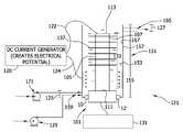
- FIG. 1provides a treatment chamber, generally indicated at 121 , to be used in the processes of the present disclosure to energize and electrically charge adsorbents in accordance with one embodiment of the present disclosure.
- the treatment chamber 121is generally elongate and has a general inlet end 125 (a lower end in the orientation of the illustrated embodiment) and a general outlet end 127 (an upper end in the orientation of the illustrated embodiment).
- the treatment chamber 121is configured such that fluid (e.g., aqueous effluent containing functional compounds to be adsorbed to an adsorbent and added to a substrate) enters the treatment chamber 121 generally at the inlet end 125 thereof, flows generally longitudinally within the chamber (e.g., upward in the orientation of illustrated embodiment) and exits the chamber generally at the outlet end 127 of the chamber.
- fluide.g., aqueous effluent containing functional compounds to be adsorbed to an adsorbent and added to a substrate
- upper and lowerare used herein in accordance with the vertical orientation of the treatment chamber 121 illustrated in the various drawings and are not intended to describe a necessary orientation of the chamber in use. That is, while the chamber 121 is most suitably oriented vertically, with the outlet end 127 of the chamber above the inlet end 125 as illustrated in the various drawings, it is understood that the chamber may be oriented with the inlet end above the outlet end, or it may be oriented other than in a vertical orientation (see FIGS. 4-6 ) and remain within the scope of this disclosure.
- axial and “longitudinal”refer directionally herein to the vertical direction of the chamber 121 (e.g., end-to-end such as the vertical direction in the illustrated embodiment of FIG. 1 ).
- transverserefer herein to a direction normal to the axial (e.g., longitudinal) direction.
- inner and outerare also used in reference to a direction transverse to the axial direction of the treatment chamber 121 , with the term “inner” referring to a direction toward the interior of the chamber and the term “outer” referring to a direction toward the exterior of the chamber.
- the inlet end 125 of the treatment chamber 121is in fluid communication with a suitable intake system, generally indicated at 129 , that is operable to direct one or more aqueous effluents to, and more suitably through, the chamber 121 .
- a suitable intake systemgenerally indicated at 129
- the intake system 129may comprise one or more pumps operable to pump the respective effluents from a corresponding source thereof to the inlet end 125 of the chamber 121 via suitable conduits (not shown).
- the intake system 129may be configured to deliver more than one aqueous solution to the treatment chamber 121 without departing from the scope of this disclosure. It is also contemplated that intake systems other than that illustrated in FIG. 1 and described herein may be used to deliver one or more effluents to the inlet end 125 of the treatment chamber 121 without departing from the scope of this disclosure.
- the inlet end 125may be in fluid communication with an air sparge, generally indicated at 171 , designed to force air into the interior of the housing.
- the air sparge 171facilitates the flow of liquid (e.g., aqueous effluent) transversely inward toward the horn to thereby facilitate ultrasonic energization (i.e., agitation) of the liquid.
- the airis forced through a porous media so as to create small air bubbles.
- the air sparged used in the treatment chamberhas a gas diffuser porosity rated from medium to fine and a gas flow rate of from about 0.01 liters per minute to about 100 liters per minute and, more suitably, from about 10 liters per minute to about 50 liters per minute.
- the air spargeforces air into the interior of the housing at a gas pressure of from about 0.2 psi to about 100 psi and, more suitably, from about 10 psi to about 50 psi, depending upon the desired gas flow rate and back pressure of the treatment system.
- the treatment chamber 121comprises a housing 151 defining an interior space 153 of the chamber through which liquid delivered to the chamber flows from the inlet end 125 to the outlet end 127 thereof.
- the housing 151suitably comprises an elongate tube 155 generally defining, at least in part, a sidewall 157 of the chamber 121 .
- the tube 155may have one or more inlet ports (one such inlet port being illustrated in FIG. 1 and indicated at 159 ) formed therein through which one or more effluents to be treated within the chamber 121 are delivered to the interior space 153 thereof. It should be understood by one skilled in the art that the inlet end of the housing may include more than one port.
- the housingmay comprise two inlet ports, wherein the first inlet port and the second inlet port are suitably in parallel, spaced relationship with each other.
- the housingmay comprise two inlet ends 269 and 279 .
- the two inlet ends 269 and 279may further independently include at least one inlet port (indicated generally at 235 and 245 , respectively).
- the housingfurther comprises an inlet collar (not shown) that is connected to and mounted on one end of the tube to further define (along with the inlet port) the inlet end of the chamber.
- the inlet collar at the inlet end of the chamberis generally annular and has at least one, and more suitably a plurality of inlet ports formed therein for receiving aqueous effluents into the interior space of the chamber.
- At least one inlet portis oriented generally tangentially relative to the annular collar so that liquid flows into the interior space of the chamber generally tangentially thereto to impart a swirling action to liquid as it enters the chamber.
- a pair of inlet portsis arranged in parallel alignment with each and extends generally tangentially relative to the annular collar, with one port being designated herein as the outer inlet port and the other port being designated the inner inlet port.
- This dual tangential inlet port arrangementis particularly useful for initiating mixing of components within the effluent before the effluent is further subjected to ultrasonic treatment and electric charge within the chamber.
- This actioncombined with the swirling action resulting from the tangential direction in which the aqueous effluent are directed into the chamber, facilitate an initial mixing of these components before the aqueous effluent flows further through the chamber for ultrasonic and electric treatment.
- additional componentsmay be delivered into the interior space of the chamber via the inlet port formed in the chamber sidewall.
- the collarmay also have an additional tangential set of inlet ports and a pair of generally vertically oriented inlet ports.
- the housing 251may comprise a closure 263 connected to and substantially closing the longitudinally opposite end of the sidewall 257 , and having at least one outlet port 265 therein to generally define the outlet end 227 of the treatment chamber 221 .
- the sidewall 257e.g., defined by the elongate tube 255
- the sidewall 257has an inner surface 267 that together with the waveguide assembly (or waveguide assemblies described further below, and generally indicated at 201 and 203 ) and the closure 263 define the interior space 253 of the chamber.
- the tube 255is generally cylindrical so that the chamber sidewall 257 is generally annular in cross-section.
- the cross-section of the chamber sidewall 257may be other than annular, such as polygonal or another suitable shape, and remains within the scope of this disclosure.
- the chamber sidewall 257 of the illustrated chamber 221is suitably constructed of a transparent material, although it is understood that any suitable material may be used as long as the material is compatible with the liquid solutions being treated in the chamber, the pressure at which the chamber is intended to operate, and other environmental conditions within the chamber such as temperature.
- a waveguide assemblyextends longitudinally at least in part within the interior space 153 of the chamber 121 to ultrasonically energize liquid (and any other components of the aqueous effluent) flowing through the interior space 153 of the chamber 121 .
- the waveguide assembly 101 of the illustrated embodimentextends longitudinally from the lower or inlet end 125 of the chamber 121 up into the interior space 153 thereof to a terminal end 113 of the waveguide assembly disposed intermediate the inlet port (e.g., inlet port 159 where it is present).
- the waveguide assemblymay extend laterally from a housing sidewall of the chamber, running horizontally through the interior space thereof.
- the waveguide assembly 101is mounted, either directly or indirectly, to the chamber housing 151 as will be described later herein.
- the waveguide assembly 101suitably comprises an elongate horn assembly, generally indicated at 133 , disposed entirely with the interior space 153 of the housing 151 intermediate the inlet port 159 and the outlet port 165 for complete submersion within the liquid being treated within the chamber 121 , and more suitably, in the illustrated embodiment, it is aligned coaxially with the chamber sidewall 157 .
- the horn assembly 133has an outer surface 107 that together with the inner surface 167 of the sidewall 157 defines a flow path within the interior space 153 of the chamber 121 along which liquid and other components flow past the horn within the chamber (this portion of the flow path being broadly referred to herein as the ultrasonic treatment zone).
- the horn assembly 133has an upper end defining a terminal end of the horn assembly (and therefore the terminal end 113 of the waveguide assembly) and a longitudinally opposite lower end 111 .
- the waveguide assembly 101also comprises a booster coaxially aligned with and connected at an upper end thereof to the lower end 111 of the horn assembly 133 . It is understood, however, that the waveguide assembly 101 may comprise only the horn assembly 133 and remain within the scope of this disclosure. It is also contemplated that the booster may be disposed entirely exterior of the chamber housing 151 , with the horn assembly 133 mounted on the chamber housing 151 without departing from the scope of this disclosure.
- the waveguide assembly 101and more particularly the booster is suitably mounted on the chamber housing 151 , e.g., on the tube 155 defining the chamber sidewall 157 , at the upper end thereof by a mounting member (not shown) that is configured to vibrationally isolate the waveguide assembly (which vibrates ultrasonically during operation thereof) from the treatment chamber housing. That is, the mounting member inhibits the transfer of longitudinal and transverse mechanical vibration of the waveguide assembly 101 to the chamber housing 151 while maintaining the desired transverse position of the waveguide assembly (and in particular the horn assembly 133 ) within the interior space 153 of the chamber housing and allowing both longitudinal and transverse displacement of the horn assembly within the chamber housing.
- the mounting memberalso at least in part (e.g., along with the booster and/or lower end of the horn assembly) closes the inlet end 125 of the chamber 121 .
- suitable mounting member configurationsare illustrated and described in U.S. Pat. No. 6,676,003, the entire disclosure of which is incorporated herein by reference to the extent it is consistent herewith.
- the mounting memberis of single piece construction. Even more suitably the mounting member may be formed integrally with the booster (and more broadly with the waveguide assembly 101 ). However, it is understood that the mounting member may be constructed separate from the waveguide assembly 101 and remain within the scope of this disclosure. It is also understood that one or more components of the mounting member may be separately constructed and suitably connected or otherwise assembled together.
- the mounting memberis further constructed to be generally rigid (e.g., resistant to static displacement under load) so as to hold the waveguide assembly 101 in proper alignment within the interior space 153 of the chamber 121 .
- the rigid mounting memberin one embodiment may be constructed of a non-elastomeric material, more suitably metal, and even more suitably the same metal from which the booster (and more broadly the waveguide assembly 101 ) is constructed.
- the term “rigid”is not, however, intended to mean that the mounting member is incapable of dynamic flexing and/or bending in response to ultrasonic vibration of the waveguide assembly 101 .
- the rigid mounting membermay be constructed of an elastomeric material that is sufficiently resistant to static displacement under load but is otherwise capable of dynamic flexing and/or bending in response to ultrasonic vibration of the waveguide assembly 101 .
- suitable ultrasonic drive systems 131include a Model 20A3000 system available from Dukane Ultrasonics of St. Charles, Ill., and a Model 2000CS system available from Herrmann Ultrasonics of Schaumberg, Ill.
- the drive system 131is capable of operating the waveguide assembly 101 at a frequency in the range of about 15 kHz to about 100 kHz, more suitably in the range of about 15 kHz to about 60 kHz, and even more suitably in the range of about 20 kHz to about 40 kHz.
- Such ultrasonic drive systems 131are well known to those skilled in the art and need not be further described herein.
- the horn assembly 133comprising an elongate, generally cylindrical horn 105 having an outer surface 107 , and two or more (i.e., a plurality of) agitating members 137 connected to the horn and extending at least in part transversely outward from the outer surface of the horn in longitudinally spaced relationship with each other.
- the horn 105is suitably sized to have a length equal to about one-half of the resonating wavelength (otherwise commonly referred to as one-half wavelength) of the horn.
- the horn 105is suitably configured to resonate in the ultrasonic frequency ranges recited previously, and most suitably at 20 kHz.
- the horn 105may be suitably constructed of a titanium alloy (e.g., Ti6Al4V) and sized to resonate at 20 kHz.
- the one-half wavelength horn 105 operating at such frequenciesthus has a length (corresponding to a one-half wavelength) in the range of about 4 inches to about 6 inches, more suitably in the range of about 4.5 inches to about 5.5 inches, even more suitably in the range of about 5.0 inches to about 5.5 inches, and most suitably a length of about 5.25 inches (133.4 mm).
- the treatment chamber 121may include a horn 105 sized to have any increment of one-half wavelength without departing from the scope of this disclosure.
- the agitating members 137comprise a series of six washer-shaped rings that extend continuously about the circumference of the horn 105 in longitudinally spaced relationship with each other and transversely (e.g., radially in the illustrated embodiment) outward from the outer surface of the horn. In this manner the vibrational displacement of each of the agitating members 137 relative to the horn 105 is relatively uniform about the circumference of the horn. It is understood, however, that the agitating members 137 need not each be continuous about the circumference of the horn 105 .
- the agitating members 137may instead be in the form of spokes, blades, fins or other discrete structural members that extend transversely outward from the outer surface 107 of the horn 105 .
- two of the six agitating membersare in a T-shape 701 , 703 , 705 , and 707 .
- the two agitating members surrounding the nodal regionas described more fully below, are in a T-shape. It has been found that members in the T-shape, generate a strong radial (e.g., horizontal) acoustic wave that further increases the cavitation effect as described more fully herein.
- the horn assembly 133 of the illustrated embodiment of FIG. 1has a length of about 5.25 inches (133.4 mm), one of the rings 137 is suitably disposed adjacent the terminal end 113 of the horn 105 (and hence of the waveguide assembly 101 ), and more suitably is longitudinally spaced approximately 0.063 inches (1.6 mm) from the terminal end of the horn 105 .
- the uppermost ring 137may be disposed at the terminal end of the horn 105 and remain within the scope of this disclosure.
- the rings 137are each about 0.125 inches (3.2 mm) in thickness and are longitudinally spaced from each other (between facing surfaces of the rings) a distance of about 0.875 inches (22.2 mm).
- the number of agitating members 137may be less than or more than six without departing from the scope of this disclosure. It is also understood that the longitudinal spacing between the agitating members 137 may be other than as illustrated in FIG. 1 and described above (e.g., either closer or spaced further apart). Furthermore, while the rings 137 illustrated in FIG. 1 are equally longitudinally spaced from each other, it is alternatively contemplated that where more than two agitating members are present the spacing between longitudinally consecutive agitating members need not be uniform to remain within the scope of this disclosure. Furthermore, as illustrated in FIGS. 4-6 , when the waveguide assembly extends laterally within the interior space of the chamber, the agitating members may be laterally spaced from one another.
- the locations of the agitating members 137are at least in part a function of the intended vibratory displacement of the agitating members upon vibration of the horn assembly 133 .
- the horn assembly 133has a nodal region located generally longitudinally centrally of the horn 105 (e.g., between the third and fourth rings).
- the “nodal region” of the horn 105refers to a longitudinal region or segment of the horn member along which little (or no) longitudinal displacement occurs during ultrasonic vibration of the horn and transverse (e.g., radial in the illustrated embodiment) displacement of the horn is generally maximized.
- the configuration of the one-half wavelength horn 105is such that the nodal region is particularly defined by a nodal plane (i.e., a plane transverse to the horn member at which no longitudinal displacement occurs while transverse displacement is generally maximized) is present.
- This planeis also sometimes referred to as a “nodal point”.
- agitating members 137e.g., in the illustrated embodiment, the rings
- agitating members that are disposed longitudinally further from the nodal region of the horn 105will experience primarily longitudinal displacement while agitating members that are longitudinally nearer to the nodal region will experience an increased amount of transverse displacement and a decreased amount of longitudinal displacement relative to the longitudinally distal agitating members.
- the horn 105may be configured so that the nodal region is other than centrally located longitudinally on the horn member without departing from the scope of this disclosure. It is also understood that one or more of the agitating members 137 may be longitudinally located on the horn so as to experience both longitudinal and transverse displacement relative to the horn upon ultrasonic vibration of the horn 105 .
- the agitating members 137are sufficiently constructed (e.g., in material and/or dimension such as thickness and transverse length, which is the distance that the agitating member extends transversely outward from the outer surface 107 of the horn 105 ) to facilitate dynamic motion, and in particular dynamic flexing/bending of the agitating members in response to the ultrasonic vibration of the horn.
- the agitating members 137 and horn 105are suitably constructed and arranged to operate the agitating members in what is referred to herein as an ultrasonic cavitation mode at the predetermined frequency.
- the ultrasonic cavitation mode of the agitating membersrefers to the vibrational displacement of the agitating members sufficient to result in cavitation (i.e., the formation, growth, and implosive collapse of bubbles in a liquid) of the liquid being treated at the predetermined ultrasonic frequency.
- the liquid flowing within the chambercomprises an aqueous effluent, and more particularly water
- the ultrasonic frequency at which the waveguide assembly 101 is to be operatedi.e., the predetermined frequency
- the agitating members 137are suitably constructed to provide a vibrational displacement of at least 1.75 mils (i.e., 0.00175 inches, or 0.044 mm) to establish a cavitation mode of the agitating members.
- the waveguide assembly 101may be configured differently (e.g., in material, size, etc.) to achieve a desired cavitation mode associated with the particular liquid being treated. For example, as the viscosity of the liquid being treated changes, the cavitation mode of the agitating members may need to be changed.
- the cavitation mode of the agitating memberscorresponds to a resonant mode of the agitating members whereby vibrational displacement of the agitating members is amplified relative to the displacement of the horn.
- cavitationmay occur without the agitating members operating in their resonant mode, or even at a vibrational displacement that is greater than the displacement of the horn, without departing from the scope of this disclosure.
- the transverse length of the agitating memberalso at least in part defines the size (and at least in part the direction) of the flow path along which liquid or other flowable components in the interior space of the chamber flows past the horn.
- the hornmay have a radius of about 0.875 inches (22.2 mm) and the transverse length of each ring is, as discussed above, about 0.5 inches (12.7 mm).
- the radius of the inner surface of the housing sidewallis approximately 1.75 inches (44.5 mm) so that the transverse spacing between each ring and the inner surface of the housing sidewall is about 0.375 inches (9.5 mm). It is contemplated that the spacing between the horn outer surface and the inner surface of the chamber sidewall and/or between the agitating members and the inner surface of the chamber sidewall may be greater or less than described above without departing from the scope of this disclosure.
- the horn 105may be constructed of a metal having suitable acoustical and mechanical properties.
- suitable metals for construction of the horn 105include, without limitation, aluminum, monel, titanium, stainless steel, and some alloy steels. It is also contemplated that all or part of the horn 105 may be coated with another metal such as silver, platinum, gold, palladium, lead dioxide, and copper to mention a few.
- the agitating members 137are constructed of the same material as the horn 105 , and are more suitably formed integrally with the horn. In other embodiments, one or more of the agitating members 137 may instead be formed separate from the horn 105 and connected thereto.
- agitating members 137e.g., the rings illustrated in FIG. 1 are relatively flat, i.e., relatively rectangular in cross-section, it is understood that the rings may have a cross-section that is other than rectangular without departing from the scope of this disclosure.
- the term “cross-section”is used in this instance to refer to a cross-section taken along one transverse direction (e.g., radially in the illustrated embodiment) relative to the horn outer surface 107 ).
- the agitating members 137e.g., the rings illustrated in FIG.
- one or more of the agitating membersmay have at least one longitudinal (e.g., axial) component to take advantage of transverse vibrational displacement of the horn (e.g., at and near the nodal region of the horn illustrated in FIG. 1 ) during ultrasonic vibration of the waveguide assembly 101 .
- the proximal end of the horn 105is suitably spaced longitudinally from the inlet port 125 in FIG. 1 to define what is referred to herein as a liquid intake zone in which initial swirling of liquid within the interior space 153 of the chamber housing 151 occurs upstream of the horn 105 .
- This intake zoneis particularly useful where the treatment chamber 121 is used for mixing two or more components together whereby initial mixing is facilitated by the swirling action in the intake zone as the components to be mixed enter the chamber housing 151 .
- the proximal end of the horn 105may be nearer to the inlet port 125 than is illustrated in FIG. 1 , and may be substantially adjacent to the inlet port so as to generally omit the intake zone, without departing from the scope of this disclosure.
- a baffle assemblygenerally indicated at 245 is disposed within the interior space 253 of the chamber 221 , and in particular generally transversely adjacent the inner surface 267 of the sidewall 257 and in generally transversely opposed relationship with the horn 205 .
- the baffle assembly 245comprises one or more baffle members 247 disposed adjacent the inner surface 267 of the housing sidewall 257 and extending at least in part transversely inward from the inner surface of the sidewall toward the horn 205 .
- the one or more baffle members 247extend transversely inward from the housing sidewall inner surface 267 to a position longitudinally intersticed with the agitating members 237 that extend outward from the outer surface 207 of the horn 205 .
- the term “longitudinally intersticed”is used herein to mean that a longitudinal line drawn parallel to the longitudinal axis of the horn 205 passes through both the agitating members 237 and the baffle members 247 .
- the baffle assembly 245comprises five, generally annular baffle members 247 (i.e., extending continuously about the horn 205 ) longitudinally intersticed with the six agitating members 237 .
- the five annular baffle members 247 illustrated in FIG. 2Aare of the same thickness as the agitating members 237 in our previous dimensional example (i.e., 0.125 inches (3.2 mm)) and are spaced longitudinally from each other (e.g., between opposed faces of consecutive baffle members) equal to the longitudinal spacing between the rings (i.e., 0.875 inches (22.2 mm)).
- Each of the annular baffle members 247has a transverse length (e.g., inward of the inner surface 267 of the housing sidewall 257 ) of about 0.5 inches (12.7 mm) so that the innermost edges of the baffle members extend transversely inward beyond the outermost edges of the agitating members 237 (e.g., the rings). It is understood, however, that the baffle members 247 need not extend transversely inward beyond the outermost edges of the agitating members 237 of the horn 205 to remain within the scope of this disclosure.
- openingsmay be formed in the baffle members other than at the outer edges where the baffle members abut the housing, and remain within the scope of this disclosure. It is also understood, that these notches may number more or less than four, as discussed above, and may even be completely omitted.
- baffle members 247 illustrated in FIG. 2Aare each generally flat, e.g., having a generally thin rectangular cross-section, it is contemplated that one or more of the baffle members may each be other than generally flat or rectangular in cross-section to further facilitate the flow of gas bubbles along the interior space 253 of the chamber 221 .
- cross-sectionis used in this instance to refer to a cross-section taken along one transverse direction (e.g., radially in the illustrated embodiment, relative to the horn outer surface 207 ).
- the treatment chamber 121is further connected to an electrical conducting generator, such as a DC current generator (indicated at 120 ), for creating an electrical potential within the interior space 153 of the chamber housing 151 .
- an electrical conducting generatorsuch as a DC current generator (indicated at 120 )
- the performance of the electrochemical reactoroften suffers from mass-transport limitations and the size of the specific electrode area.
- one of the main factors that control the rate of a chemical reactionis the rate at which the reactants come together.
- the generator 120can be connected to the chamber 121 through electrical wires (indicated at 122 and 124 ) to one or more components of the treatment chamber 121 .
- electrical wires 122 and 124electrically connect the DC current generator 120 to the terminal end of the horn 105 (e.g., the terminal end 113 of the waveguide assembly 101 ) and the sidewall 157 of the chamber housing 151 , respectively.
- the electrical current producedcreates an electrode potential such that the sidewall of the chamber housing shows properties typical of an anode and the horn shows the properties of a cathode, or vice versa.
- the electrode potential produced by the generator 120 of the present disclosureis in the range of from about 0.1V to about 15V. More suitably, the electrode potential is in the range of from about 0.5V to about 5.0V and, more suitably, from about 1.0V to about 3.0V. Furthermore, typical current density produced by the electrode potential within the treatment chamber ranges from about 0.1 kA/m 2 to a bout 2 kA/m 2 and, more suitably, the current density can be from about 1 kA/m 2 to about 1.5 kA/m 2 .
- the electrode potentialwill be determined and produced in an amount required for the desired purpose of treatment chamber.
- the electrode potential producedwill be that which is necessary to produce a positively charged adsorbent on the outer surface of the horn (e.g., anode).
- the electrode potential producedwill be that which is necessary to produce a less positively charged or negatively charged adsorbent on the outer surface of the horn (e.g., cathode).
- the generator 120is connected to the sidewall 157 and the terminal end 119 of the horn 105 in FIG. 1 , the generator can be connected to numerous other areas of the treatment chamber 21 without departing from the scope of this disclosure.
- the electrical wirescan connect the generator to multiple waveguide assemblies, each being fully disposed within the interior of the chamber housing of a single treatment chamber. More particularly, as illustrated in FIGS.
- the housing 151As there is an electrode potential produced within the interior 153 of the chamber housing 151 by connecting the sidewall 157 of the housing 151 and the outer surface 107 of the horn 105 to a generator 120 , it is desirable for the housing 151 to be electrically insulated from the waveguide assembly 101 to maintain the electrode-like effect. As such, in the illustrated embodiment, the housing sidewall 157 is separated from the waveguide assembly 101 (and thus, the horn 105 ) by at least two insulating members 10 and 12 .
- the insulating members 10 , 12can be made using any insulating material known in the art.
- the insulating members 10 , 12may be produced using any one of a multitude of known inorganic or organic insulating materials.
- Particularly suitable materials that could be used for the insulating members 10 , 12include solid materials with a high dielectric strength, such as for example, glass, mylar, kapton, ceramic, phenolic glass/epoxy laminates, and the like.
- the liquid, containing the produced carrier componentis exhausted from the treatment chamber 121 through at least one outlet end 127 .
- the outlet end 127is capable of letting the liquid escape from the chamber 121 , while providing enough flow resistance to keep the pressure within the chamber 121 at a suitable level.
- the pressure within the chamber 121is maintained within a range of from about 1 pound/square inch (psi) to about 10 psi. While the illustrated embodiment of FIG.
- FIG. 1depicts a treatment chamber 121 having only one outlet port 165 in the outlet end 127 , it should be understood that the treatment chamber used in the processes of the present disclosure can suitably contain more than one inlet port and inlet end without departing from the scope of this disclosure.
- substratesthat will benefit from the functional compounds delivered by the delivery system include substrates such as woven and non-woven materials made from a polyolefin polymer such as polypropylene, polyethylene, polyester, and the like. These substrates are then used in products such as child care articles, face mask fabrics, air filtration fabrics, medical gowns, medical drapes, wipes, hand towels, facial tissue, bath tissue, transdermal delivery devices, wound dressings, automobile covers, boat covers, and deck furniture.
- substratessuch as woven and non-woven materials made from a polyolefin polymer such as polypropylene, polyethylene, polyester, and the like.
- substrates made from synthetic polymerscan undergo a pretreatment process for increasing the negative surface charge.
- pretreatment processesinclude subjecting the substrate to a corona treatment or to an electret treatment.
- An electret treatmentfor example, is disclosed in U.S. Pat. No. 5,964,926 issued to Cohen, which is incorporated herein by reference in its entirety.
- Such pretreatmentshave been found not only to increase the negative surface charge of polymeric materials, but also assist in wetting out the polymer and enhancing surface adhesion between the polymer and the carrier component of the delivery system of the present disclosure.
- substrates contacted with the carrier componentscan also undergo various post treatment processes which further serve to affix the components to the substrate.
- the substratescan be subjected to radio frequency radiation or to microwave radiation.
- Adsorbentssuch as alumina, are known to adsorb radio frequency and microwave radiation causing the carrier components to heat. Once heated, it is believed that the components become further embedded into the polymeric substrate. Further, the particles can be heated without also heating the substrate to higher than desired temperatures.
- the substrateis the skin of a patient.
- the carrier componentcan be combined with a lotion or formulation for transdermal use.
- the carrier componentcan contain a UV absorber and be combined with a skin care formulation to be used as a sunscreen lotion or sunblock.
- the substrateis tissue inside of the body of a patient, such as an organ or muscle.
- the carrier componentcan be administered to the patient orally, parenterally, intraperitoneally, intravenously, or intradermally.
- the carrier component of the delivery systemcan be used with capsules, tablets, pills, powders, and granules for oral administration.
- the carrier componentsare ordinarily combined with one or more adjuvants appropriate to the indicated route of administration.
- Liquid dosage forms for oral administrationcan include pharmaceutically acceptable emulsions, solutions, suspensions, syrups, and elixirs containing inert diluents commonly used in the art, such as water.
- Such delivery systemscan also comprise adjuvants, such as wetting agents, emulsifying and suspending agents, and sweetening, flavoring, and perfuming agents.
- the delivery systems containing the carrier componentscan be injected into the patient for the purpose of delivering the functional compounds.
- the componentcan be contacted with the patient parenterally, intraperitoneally, intratumor, or intrapleural.
- parentalas used herein includes subcutaneous, intravenous, intramuscular, or intrasternal injection, or infusion technique.
- Injectable delivery system preparationsfor example sterile injectable aqueous or oleaginous suspensions, can be formulated according to the known art using suitable dispersing or wetting agents and suspending agents.
- suitable dispersing or wetting agents and suspending agentsinclude water, Ringer's solution, and isotonic sodium chloride solution.
- sterile, fixed oilsare conventionally employed as a solvent or suspending medium.
- any bland fixed oilmay be employed, including synthetic mono- or diglycerides.
- fatty acidssuch as oleic acid are useful in the preparation of injectables.
- Dimethyl acetamide, surfactants including ionic and non-ionic detergents, and polyethylene glycolscan also be used. Mixtures of solvents and wetting agents discussed herein are also useful.
- the delivery systemis administered parentally.
- Formulations for parenteral administrationcan be in the form of aqueous or non-aqueous isotonic sterile injection solutions or suspensions. These solutions and suspensions can be prepared from sterile powders or granules having one or more of the diluents mentioned for the use in the formulations for oral administration.
- the carrier componentscan be dissolved in water, polyethylene glycol, propylene glycol, ethanol, corn oil, cottonseed oil, peanut oil, sesame oil, benzyl alcohol, sodium chloride, and/or various buffers. Other adjuvants and modes of administration are well and widely known in the pharmaceutical art.
- the bound functional compound in the delivery systemcan be used with or without a triggerable release.
- the functional compoundscan be selectively released by an environmentally created pH trigger, such as by either a basic or acidic environmental condition.
- the functional compoundcan be an antifungal compound that is released in the basic/alkaline environment of a vagina with a yeast infection.
- the functional compoundis an anti-microbial to treat an infection in the basic environment of the small intestine after it has passed through the acidic environment of the stomach.
- triggering mechanismscan suitably include exposure to changes in temperature, moisture, chemical stimuli, body exudates, and combinations thereof.
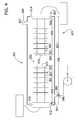
- the treatment chambercan include more than one waveguide assembly having at least two horn assemblies for ultrasonically treating and electrically charging adsorbent.
- the treatment chamber 221comprises a housing 251 defining an interior space 253 of the chamber 221 through which liquid is delivered from two laterally opposing inlet ends 269 and 279 .
- the housing 251comprises an elongate tube 255 defining, at least in part, a sidewall 257 of the chamber 221 .
- the tube 255has two inlet ports 240 and 245 formed therein and being laterally opposed to one another through which one or more functional compounds in an aqueous effluent to be adsorbed within the chamber 221 are delivered to the interior space 253 thereof, and at least one outlet port 265 through which the liquid, once treated, exits the chamber 221 .
- Two waveguide assemblies 201 and 203extend longitudinally at least in part within the interior space 253 of the chamber 221 to ultrasonically energize adsorbent located within the interior space 253 of the chamber 221 .
- Each waveguide assembly 201 and 203separately includes an elongate horn assembly, generally indicated at 233 and 235 , respectively, each disposed entirely within the interior space 253 of the housing 251 intermediate the inlet ports 269 and 279 and the outlet port 265 for complete submersion within the liquid within the chamber 221 .
- Each horn assembly 233 and 235can be independently constructed as described (including the horns 205 and 209 , along with the plurality of agitating members 237 and 239 and baffle assemblies 245 and 249 ) for the single horn assembly configuration of FIG. 1 above.
- a generator(not shown) can be electrically connected to the outside surfaces 207 and 211 of horns 205 and 209 , respectively, of the two horn assemblies 233 and 235 to create an electrode potential within the interior 253 of the housing 251 of the chamber 221 .
- the adsorbent (not shown) located on the outer surface 211 of the second horn 209is electrically charged as an anode
- the adsorbent (not shown) located on the outer surface 207 of the first horn 205is electrically charged as a cathode (see also FIG.
- the housing 251is separated from the first waveguide assembly 201 using at least a first insulating member 210 and at least a second insulating member 212 and from the second waveguide assembly 203 using at least a third insulating member 214 and at least a fourth insulating member 216 .
- the treatment chamber 421is similar to the treatment chamber 221 of FIG. 2A in that the chamber 421 contains two separate waveguide assemblies 401 and 403 .
- the waveguide assemblies 401 , 403 of FIG. 3are further separated within the interior space 453 of the housing 451 by a mesh substrate 450 that runs laterally between the first waveguide assembly 401 and the second waveguide assembly 403 .
- the mesh substrate 450extends from the upper longitudinal end (e.g., first longitudinal end) of the housing, generally indicated at 463 (e.g., corresponding to closure 263 of FIG. 2A ) to the lower longitudinal end (e.g., second longitudinal end) of the housing, generally indicated at 473 .
- the mesh substrateis generally capable of separating gases being generated as compounds are electrolyzed from the liquid. For example, in the electrolysis of ammonia, nitrogen gas is formed at the anode and hydrogen gas is formed at the cathode. It is desirable to keep these gases separate for later resale purposes.
- the mesh substratecan be used to allow formed ions to migrate across the treatment chamber from the anode to the cathode so as to keep ionic neutrality in the entire liquid.
- the electrolysis of waterforms hydrogen gas and oxygen gas.
- oxygen gasis formed along with the hydrogen ion (H + ) and, at the cathode, hydrogen gas is formed along with the hydroxyl ion (OH ⁇ ). Both the hydrogen and hydroxyl ions can migrate across this mesh substrate so as to maintain ionic neutrality within the interior of the treatment chamber.
- the mesh substratecan be made of any suitable material known in the art.
- one particular material for the mesh substrateis stainless steel.
- Further examplesinclude, mesh substrates made from polyethylene, polypropylene, and perfluorinated materials.
- the mesh substratehas a pore size of from about 15 microns to about 450 microns and, more suitably, from about 20 microns to about 100 microns.
- the mesh substratetypically has a thickness of from about 0.001 inches to a bout 0.05 inches and, more suitably, from about 0.005 inches to about 0.04 inches.
- the housing 451As the treatment chamber 421 is divided into two compartments by the mesh substrate 450 , it is suitable for the housing 451 to include more than one outlet port. Specifically, in the illustrated embodiment, there are two outlet ports 427 and 429 . More specifically, the first outlet port 427 allows liquid that has had functional compounds removed and adsorbed by the adsorbent located on the first waveguide assembly 401 to exit the interior space 453 of the chamber housing 451 , and the second outlet port 429 allows liquid that has had functional compounds removed and adsorbed by the adsorbent located on the second waveguide assembly 403 to exit the interior space 453 of the chamber housing 451 . It should be understood by one skilled in the art that, while FIG. 3 depicts two outlet ports, the housing 451 of the treatment chamber 421 may include more than two outlet ports, or alternatively only one outlet port, without departing from the scope of this disclosure.
- the treatment chamber 521is generally elongate, however, in contrast to FIGS. 1-3 , the treatment chamber 521 is configured such that fluid enters the chamber 521 at the inlet end 535 thereof, flows generally laterally within the chamber (e.g., toward the right in the orientation of illustrated embodiment) and exits the chamber 521 generally at the outlet end 527 of the chamber 521 .
- the treatment chamber 521comprises a housing 551 defining an interior space 553 of the chamber 521 through which liquid is delivered from at least one inlet port 569 .
- the housing 551comprises an elongate tube 555 defining, at least in part, a sidewall 557 of the chamber 521 .
- the housing 551has two longitudinally opposing ends through which one or more aqueous effluents having functional compounds to be adsorbed by the adsorbent within the chamber 521 are delivered to the interior space 553 thereof, and at least one outlet port 565 through which the liquid, once the functional compounds have been adsorbed, exits the chamber 521 .
- Each waveguide assembly 501 and 503extend laterally at least in part within the interior space 553 of the chamber 521 to ultrasonically energize and electrically charge adsorbent within the interior space 553 of the chamber 521 .
- Each waveguide assembly 501 and 503separately includes an elongate horn assembly, generally indicated at 533 and 535 , respectively, each disposed entirely within the interior space 553 of the housing 551 intermediate the inlet port 569 and the outlet port 565 for complete submersion within the liquid within the chamber 521 .
- the terminal ends 573 and 575 of horn assemblies 533 and 535respectively, directly face towards each other.
- Each horn assembly 533 and 535can be independently constructed as described (including the horns 505 and 509 , along with the plurality of agitating members 537 and 539 and baffle assemblies (not shown)) for the single horn assembly configuration of FIG. 1 above.
- an electric DC current generator(not shown) can be electrically connected to the outside surfaces 507 and 511 of horns 505 and 509 , respectively, of the two horn assemblies 533 and 535 to create an electrode potential within the interior space 553 of the housing 551 of the chamber 521 .
- the outer surface 511 of the second horn 509 (and the adsorbent located thereon (not shown))is electrically charged as an anode, while the outer surface 507 of the first horn 505 (and the adsorbent located thereon (not shown)) is electrically charged as a cathode.
- the housing 551is separated from the first waveguide assembly 501 using at least a first insulating member 510 and at least a second insulating member 512 and from the second waveguide assembly 503 using at least a third insulating member 514 and at least a fourth insulating member 516 .
- the terminal ends 673 and 675 of horn assemblies 633 and 635face away from each other.
- the waveguide assemblies 633 and 635are separated within the interior space 653 of the housing 651 by a mesh substrate 650 , similar to the mesh substrate of FIG. 3 , that runs laterally between the first waveguide assembly 601 and the second waveguide assembly 603 .
- the mesh substrate 650extends from the upper longitudinal end (e.g., first longitudinal end) of the housing, generally indicated at 663 (e.g., corresponding to closure 263 of FIG. 2A ) to the lower longitudinal end (e.g., 2nd longitudinal end) of the housing, generally indicated at 678 .
- the mesh substrate 650provides structural support to the first waveguide assembly 601 and second waveguide assembly 603 , and more particularly, is constructed to substantially vibrationally isolate the first waveguide assembly 601 and second waveguide assembly 603 within the interior space 653 from the chamber housing 651 .
- the first waveguide assembly 601 and the second waveguide assembly 603can suitably be mounted on the mesh substrate 650 by a mounting member (not shown).
- the mounting member used as described above for the illustrated embodiment of FIG. 1can be used as the mounting member in this embodiment.
- the housing 651As the treatment chamber 621 is divided into two compartments by the mesh substrate 650 , it is suitable for the housing 651 to include more than one inlet port (as illustrated, the housing includes a first inlet port, generally indicated at 669 , and a second inlet port, generally indicated at 679 ) and more than one outlet port (as illustrated, the housing includes a first outlet port, generally indicated at 627 , and a second outlet port, generally indicated at 629 ).
- the first inlet port 669allows one or more liquid solutions having functional compounds to enter into the interior space 653 of the chamber housing 651 to be adsorbed by adsorbent located the first waveguide assembly 601 and then the first outlet port 627 allows liquid that has had functional compounds removed and adsorbed by the adsorbent located on the first waveguide assembly 601 to exit the interior space 653 of the chamber housing 651
- the second inlet port 679allows one or more liquid solutions having functional compounds to enter into the interior space 653 of the chamber housing 651 to be adsorbed by the adsorbent located on the second waveguide assembly 603 and then the second outlet port 629 allows liquid that has had functional compounds removed and adsorbed by adsorbent located on the second waveguide assembly 603 to exit the interior space 653 of the chamber housing 651 .
- the treatment chamber 721is generally elongate and configured such that fluid enters the chamber 721 at the inlet end 759 thereof, flows generally laterally within the chamber (e.g., toward the left in the orientation of illustrated embodiment) and exits the chamber 721 generally at the outlet end 727 of the chamber 721 .
- the treatment chamber 721comprises a housing 751 defining an interior space 753 of the chamber 721 through which liquid is delivered from at least one inlet port 769 .
- the housing 751comprises an elongate tube 755 defining, at least in part, a sidewall 757 of the chamber 721 .
- the housing 751has two longitudinally opposing ends through which one or more liquid solutions having functional compounds to be adsorbed within the chamber 721 are delivered to the interior space 753 thereof, and at least one outlet port 765 through which the liquid exits the chamber 721 .
- Each waveguide assembly 701 and 703extend laterally at least in part within the interior space 753 of the chamber 721 to ultrasonically energize and electrically charge adsorbent within the interior space 753 of the chamber 721 .
- Each waveguide assembly 701 and 703separately includes an elongate horn assembly, generally indicated at 733 and 735 , respectively, each disposed entirely within the interior space 753 of the housing 751 intermediate the inlet port 769 and the outlet port 765 for complete submersion within the liquid within the chamber 721 .
- the second horn, indicated generally at 709 , of second horn assembly 735 of the second waveguide assembly 703is configured in a hollow cylinder shape.
- the first horn member, indicated at 715 , of the first horn assembly 733 of the first waveguide assembly 701is disposed lengthwise within the hollow cylinder shaped second horn 709 .
- the second horncan be configured in a U-shape and includes two arm members.
- the first horn member of the first horn assembly of the first waveguide assemblyis disposed between the first arm member and the second arm member of the second horn.
- this configurationcan allow for better overlap of the agitating members, producing increased cavitation.
- each horn assembly 733 and 735can further include the plurality of agitating members 737 and 739 , respectively, and baffle assemblies (not shown) as with the single horn assembly configuration of FIG. 1 above.
- the treatment chamber 821comprises a housing 851 defining an interior space 853 of the chamber 821 through which liquid is delivered from three laterally aligned inlet ends 869 , 879 and 889 .
- the housing 851comprises an elongate tube defining, at least in part, a sidewall 857 of the chamber 821 .
- the tubehas three inlet ports 840 , 845 and 850 formed therein and being laterally aligned to one another through which one or more liquid solutions or components to be treated within the chamber 821 are delivered to the interior space 853 thereof, and at least one outlet port 865 through which the liquid, once treated, exits the chamber 821 .
- Each waveguide assembly 801 and 803extend longitudinally at least in part within the interior space 853 of the chamber 821 to ultrasonically energize liquid flowing through the interior space 853 of the chamber 821 .
- Each waveguide assembly 801 and 803separately includes a plate-like elongate horn assembly, generally indicated at 833 and 835 , respectively, each disposed entirely within the interior space 853 of the housing 851 intermediate the inlet ports 869 , 879 and 889 and the outlet port 865 for complete submersion within the liquid being treated within the chamber 821 .
- Each horn assembly 833 and 835can be independently constructed as described (including the horns 805 and 809 , along with the plurality of agitating members 837 and 839 and baffle assemblies (not shown)) for the single horn assembly configuration of FIG. 1 above.
- the agitating members 837 and 839when present, are flat disk-like pieces that surround the outer surface of the plate-like horn members.
- a generator(not shown) can be electrically connected to the outside surfaces of horns 805 and 809 as discussed of the treatment chamber in FIG. 2A above.
Landscapes
- Chemical & Material Sciences (AREA)
- Engineering & Computer Science (AREA)
- Organic Chemistry (AREA)
- Metallurgy (AREA)
- Health & Medical Sciences (AREA)
- Materials Engineering (AREA)
- Electrochemistry (AREA)
- Chemical Kinetics & Catalysis (AREA)
- Radiology & Medical Imaging (AREA)
- Veterinary Medicine (AREA)
- Public Health (AREA)
- General Health & Medical Sciences (AREA)
- Animal Behavior & Ethology (AREA)
- Life Sciences & Earth Sciences (AREA)
- Nuclear Medicine, Radiotherapy & Molecular Imaging (AREA)
- Biomedical Technology (AREA)
- Physical Or Chemical Processes And Apparatus (AREA)
- Medicinal Preparation (AREA)
Abstract
Description


a tautomer thereof, or a functional equivalent thereof, wherein R and R′ independently comprise a hydrogen, an alkyl group, or an aryl group. As used herein, a “functional equivalent” to one of the above moieties refers to functional compounds that include similar reactive groups as shown above, but which are not positioned on the molecule exactly as shown above and yet will bond with the energized adsorbent in a similar manner. Furthermore, it should be understood that various additional R groups may be included with the above moieties as long as the R groups do not interfere with the bond that is formed with the energized adsorbent.


Claims (20)
Priority Applications (6)
| Application Number | Priority Date | Filing Date | Title |
|---|---|---|---|
| US11/777,145US7785674B2 (en) | 2007-07-12 | 2007-07-12 | Delivery systems for delivering functional compounds to substrates and processes of using the same |
| KR20107003103AKR101494481B1 (en) | 2007-07-12 | 2008-07-09 | Delivery systems for delivering functional compounds to substrates and processes of using the same |
| CN2008801067660ACN101801451B (en) | 2007-07-12 | 2008-07-09 | Delivery systems for delivering functional compounds to substrates and processes of using the same |
| PCT/IB2008/052760WO2009007920A2 (en) | 2007-07-12 | 2008-07-09 | Delivery systems for delivering functional compounds to substrates and processes of using the same |
| BRPI0812630ABRPI0812630A2 (en) | 2007-07-12 | 2008-07-09 | of functional compounds to a substrate |
| EP08789242.8AEP2175922B1 (en) | 2007-07-12 | 2008-07-09 | Delivery systems for delivering functional compounds to substrates and processes of using the same |
Applications Claiming Priority (1)
| Application Number | Priority Date | Filing Date | Title |
|---|---|---|---|
| US11/777,145US7785674B2 (en) | 2007-07-12 | 2007-07-12 | Delivery systems for delivering functional compounds to substrates and processes of using the same |
Publications (2)
| Publication Number | Publication Date |
|---|---|
| US20090017225A1 US20090017225A1 (en) | 2009-01-15 |
| US7785674B2true US7785674B2 (en) | 2010-08-31 |
Family
ID=40229185
Family Applications (1)
| Application Number | Title | Priority Date | Filing Date |
|---|---|---|---|
| US11/777,145Expired - Fee RelatedUS7785674B2 (en) | 2007-07-12 | 2007-07-12 | Delivery systems for delivering functional compounds to substrates and processes of using the same |
Country Status (6)
| Country | Link |
|---|---|
| US (1) | US7785674B2 (en) |
| EP (1) | EP2175922B1 (en) |
| KR (1) | KR101494481B1 (en) |
| CN (1) | CN101801451B (en) |
| BR (1) | BRPI0812630A2 (en) |
| WO (1) | WO2009007920A2 (en) |
Cited By (15)
| Publication number | Priority date | Publication date | Assignee | Title |
|---|---|---|---|---|
| US20090014393A1 (en)* | 2007-07-12 | 2009-01-15 | Kimberly-Clark Worldwide, Inc. | Treatment chamber for separating compounds from aqueous effluent |
| US20100150859A1 (en)* | 2008-12-15 | 2010-06-17 | Kimberly-Clark Worldwide, Inc. | Methods of preparing metal-modified silica nanoparticles |
| US7998322B2 (en) | 2007-07-12 | 2011-08-16 | Kimberly-Clark Worldwide, Inc. | Ultrasonic treatment chamber having electrode properties |
| US8034286B2 (en) | 2006-09-08 | 2011-10-11 | Kimberly-Clark Worldwide, Inc. | Ultrasonic treatment system for separating compounds from aqueous effluent |
| US8057573B2 (en) | 2007-12-28 | 2011-11-15 | Kimberly-Clark Worldwide, Inc. | Ultrasonic treatment chamber for increasing the shelf life of formulations |
| US8143318B2 (en) | 2007-12-28 | 2012-03-27 | Kimberly-Clark Worldwide, Inc. | Ultrasonic treatment chamber for preparing emulsions |
| US8163388B2 (en) | 2008-12-15 | 2012-04-24 | Kimberly-Clark Worldwide, Inc. | Compositions comprising metal-modified silica nanoparticles |
| US8206024B2 (en) | 2007-12-28 | 2012-06-26 | Kimberly-Clark Worldwide, Inc. | Ultrasonic treatment chamber for particle dispersion into formulations |
| US8215822B2 (en) | 2007-12-28 | 2012-07-10 | Kimberly-Clark Worldwide, Inc. | Ultrasonic treatment chamber for preparing antimicrobial formulations |
| US8454889B2 (en) | 2007-12-21 | 2013-06-04 | Kimberly-Clark Worldwide, Inc. | Gas treatment system |
| US20130214055A9 (en)* | 2006-09-08 | 2013-08-22 | Kimberly-Clark Worldwide, Inc. | Ultrasonic liquid treatment and delivery system and process |
| US8616759B2 (en) | 2006-09-08 | 2013-12-31 | Kimberly-Clark Worldwide, Inc. | Ultrasonic treatment system |
| US8632613B2 (en) | 2007-12-27 | 2014-01-21 | Kimberly-Clark Worldwide, Inc. | Process for applying one or more treatment agents to a textile web |
| US8858892B2 (en) | 2007-12-21 | 2014-10-14 | Kimberly-Clark Worldwide, Inc. | Liquid treatment system |
| US9283188B2 (en) | 2006-09-08 | 2016-03-15 | Kimberly-Clark Worldwide, Inc. | Delivery systems for delivering functional compounds to substrates and processes of using the same |
Families Citing this family (6)
| Publication number | Priority date | Publication date | Assignee | Title |
|---|---|---|---|---|
| US9421504B2 (en)* | 2007-12-28 | 2016-08-23 | Kimberly-Clark Worldwide, Inc. | Ultrasonic treatment chamber for preparing emulsions |
| US20140163047A1 (en)* | 2009-12-21 | 2014-06-12 | Instituto Presbiteriano Mackenzie | Composition of a ceramic matrix with a controlled release drug, a tablet obtained from the composition and methods for obtaining the composition and the tablet |
| CN110167614B (en)* | 2016-10-17 | 2022-02-22 | 洁霺生医科技股份有限公司 | micro-delivery device |
| CN107413287A (en)* | 2017-08-15 | 2017-12-01 | 泰州希斯曼金属制品有限公司 | The electrochemical process for treating of the nanoscale object of bactericidal metal is used in Biomedia |
| US20220000153A1 (en)* | 2018-11-05 | 2022-01-06 | Strauss Group Ltd. | Method and system for processing a material by pressure wave |
| EP4083269A4 (en)* | 2019-12-23 | 2024-01-03 | Dipsol Chemicals Co., Ltd. | Zinc-nickel-silica composite plating bath and method for plating using said plating bath |
Citations (191)
| Publication number | Priority date | Publication date | Assignee | Title |
|---|---|---|---|---|
| US2307206A (en) | 1940-03-14 | 1943-01-05 | Armour & Co | Spraying device |
| US2584053A (en) | 1949-11-28 | 1952-01-29 | Sonic Res Corp | Means for the application of alternating shear at sonic frequencies to the treatmentof material |
| US2946981A (en) | 1954-05-05 | 1960-07-26 | Bendix Aviat Corp | Sonic transducers for fluid mediums |
| US3202281A (en) | 1964-10-01 | 1965-08-24 | Weston David | Method for the flotation of finely divided minerals |
| US3246881A (en) | 1963-07-16 | 1966-04-19 | Branson Instr | Process and apparatus for treating heat sensitive material with sonic vibrations |
| US3249453A (en) | 1961-07-29 | 1966-05-03 | Bayer Ag | Ultrasonic preparation of finely dispersed dyestuff |
| US3273631A (en) | 1964-01-13 | 1966-09-20 | Neuman Entpr Ltd | Ultrasonic fluid heating, vaporizing, cleaning and separating apparatus |
| US3275787A (en) | 1963-12-30 | 1966-09-27 | Gen Electric | Process and apparatus for producing particles by electron melting and ultrasonic agitation |
| US3325348A (en) | 1964-09-24 | 1967-06-13 | Fitchburg Paper | Ultrasonic device for placing materials in suspension |
| US3326470A (en) | 1965-04-27 | 1967-06-20 | Babcock & Wilcox Co | Liquid atomizer |
| US3338992A (en) | 1959-12-15 | 1967-08-29 | Du Pont | Process for forming non-woven filamentary structures from fiber-forming synthetic organic polymers |
| US3341394A (en) | 1966-12-21 | 1967-09-12 | Du Pont | Sheets of randomly distributed continuous filaments |
| US3479873A (en) | 1967-11-13 | 1969-11-25 | Fischer & Porter Co | Self-cleaning electrodes |
| US3490584A (en) | 1965-08-31 | 1970-01-20 | Cavitron Corp | Method and apparatus for high frequency screening of materials |
| US3502763A (en) | 1962-02-03 | 1970-03-24 | Freudenberg Carl Kg | Process of producing non-woven fabric fleece |
| US3519251A (en) | 1968-07-11 | 1970-07-07 | Frederick G Hammitt | Vibratory unit with baffle |
| US3542615A (en) | 1967-06-16 | 1970-11-24 | Monsanto Co | Process for producing a nylon non-woven fabric |
| US3542345A (en) | 1968-06-13 | 1970-11-24 | Ultrasonic Systems | Ultrasonic vials and method and apparatus for mixing materials in same |
| US3567185A (en) | 1968-10-03 | 1971-03-02 | Shell Oil Co | Fluid resonator system |
| US3664191A (en) | 1970-06-01 | 1972-05-23 | Fischer & Porter Co | Explosion-proof self-cleaning electrodes |
| US3692618A (en) | 1969-10-08 | 1972-09-19 | Metallgesellschaft Ag | Continuous filament nonwoven web |
| US3782547A (en) | 1971-10-12 | 1974-01-01 | Harry Dietert Co | Structure for ultrasonic screening |
| US3802817A (en) | 1969-10-01 | 1974-04-09 | Asahi Chemical Ind | Apparatus for producing non-woven fleeces |
| US3865350A (en) | 1974-01-14 | 1975-02-11 | Wilson A Burtis | Liquid homogenizing device |
| GB1404575A (en) | 1971-07-27 | 1975-09-03 | Kodak Ltd | Method of dispersing a pigment in a resin |
| US4062768A (en) | 1972-11-14 | 1977-12-13 | Locker Industries Limited | Sieving of materials |
| US4168295A (en) | 1975-11-20 | 1979-09-18 | Vernon D. Beehler | Apparatus for enhancing chemical reactions |
| US4218221A (en) | 1978-01-30 | 1980-08-19 | Cottell Eric Charles | Production of fuels |
| US4259021A (en) | 1978-04-19 | 1981-03-31 | Paul R. Goudy, Jr. | Fluid mixing apparatus and method |
| US4266879A (en) | 1975-01-16 | 1981-05-12 | Mcfall Richard T | Fluid resonator |
| US4340563A (en) | 1980-05-05 | 1982-07-20 | Kimberly-Clark Corporation | Method for forming nonwoven webs |
| US4372296A (en) | 1980-11-26 | 1983-02-08 | Fahim Mostafa S | Treatment of acne and skin disorders and compositions therefor |
| US4511254A (en) | 1982-12-06 | 1985-04-16 | Henry North | Cavitators |
| US4556467A (en) | 1981-06-22 | 1985-12-03 | Mineral Separation Corporation | Apparatus for ultrasonic processing of materials |
| CH657067A5 (en) | 1979-11-08 | 1986-08-15 | Cottell Eric Charles | Process for separating suspended solids and agglomerated other solids in suspending and bonding liquids respectively |
| JPS6239839U (en) | 1985-08-29 | 1987-03-10 | ||
| US4663220A (en) | 1985-07-30 | 1987-05-05 | Kimberly-Clark Corporation | Polyolefin-containing extrudable compositions and methods for their formation into elastomeric products including microfibers |
| US4673512A (en) | 1984-07-06 | 1987-06-16 | Internationale Octrooi Maatschappij "Octropfa" Bv | Particle separation |
| US4693879A (en) | 1984-10-09 | 1987-09-15 | Mitsubishi Chemical Industries Ltd. | Ultrasonic vibration sieving apparatus and process for purifying carbon black by using the apparatus |
| US4706509A (en) | 1984-10-23 | 1987-11-17 | Friedrich Loffler | Method of and an apparatus for ultrasonic measuring of the solids concentration and particle size distribution in a suspension |
| US4708878A (en) | 1983-07-13 | 1987-11-24 | Ulrich Hagelauer | Process for temperature controlling a liquid |
| US4726522A (en) | 1985-05-13 | 1988-02-23 | Toa Nenryo Kogyo Kabushiki Kaisha | Vibrating element for ultrasonic atomization having curved multi-stepped edged portion |
| US4743361A (en) | 1983-10-31 | 1988-05-10 | Internationale Octrooi Maatschappij "Octropa" Bv | Manipulation of particles |
| EP0269941A1 (en) | 1986-11-21 | 1988-06-08 | ULTRAVIOLET TECHNOLOGY ITALIA S.r.l. | Fluid sterilizing process and device |
| US4848159A (en) | 1987-05-22 | 1989-07-18 | The Boeing Company | Ultrasonic inspection probe for laminated structures |
| US4877516A (en) | 1986-05-27 | 1989-10-31 | National Research Development Corporation | Manipulating particulate matter |
| US4879011A (en) | 1987-08-07 | 1989-11-07 | National Research Development Corporation | Process for controlling a reaction by ultrasonic standing wave |
| US4929279A (en) | 1989-02-21 | 1990-05-29 | Basf Corporation | Process for dispersing organic pigments with ultrasonic radiation |
| US4983045A (en) | 1985-11-22 | 1991-01-08 | Reica Corporation | Mixer |
| DE9017338U1 (en) | 1990-12-20 | 1991-03-07 | Bandelin electronic GmbH & Co KG, 12207 Berlin | Flow vessel for a disintegrator |
| US5006266A (en) | 1987-10-14 | 1991-04-09 | National Research Development Corporation | Manipulating means utilizing ultrasonic wave energy for use with particulate material |
| US5026167A (en) | 1989-10-19 | 1991-06-25 | Heat Systems Incorporated | Ultrasonic fluid processing system |
| US5032027A (en) | 1989-10-19 | 1991-07-16 | Heat Systems Incorporated | Ultrasonic fluid processing method |
| EP0292470B1 (en) | 1987-05-19 | 1991-10-16 | Wolfgang Dipl.-Ing. Stuckart | Process for separating substances from liquids and apparatus for carrying out the process |
| US5059249A (en) | 1989-02-21 | 1991-10-22 | Basf Corp. | Process for dispersing organic pigments with ultrasonic radiation |
| EP0459967A3 (en) | 1990-05-17 | 1992-04-08 | Monsanto Company | Pigmented dispersion and its use in colored thermoplastic resin sheet |
| US5169067A (en) | 1990-07-30 | 1992-12-08 | Aisin Seiki Kabushiki Kaisha | Electromagnetically operated ultrasonic fuel injection device |
| US5242557A (en) | 1991-03-21 | 1993-09-07 | Tioxide Group Services Limited | Method for preparing pigments |
| US5258413A (en) | 1992-06-22 | 1993-11-02 | The University Of Akron | Continuous ultrasonic devulcanization of valcanized elastomers |
| US5326164A (en) | 1993-10-28 | 1994-07-05 | Logan James R | Fluid mixing device |
| US5330100A (en) | 1992-01-27 | 1994-07-19 | Igor Malinowski | Ultrasonic fuel injector |
| US5335449A (en) | 1991-08-15 | 1994-08-09 | Net/Tech International, Inc. | Delivery system for an agriculturally active chemical |
| US5391000A (en) | 1990-03-07 | 1995-02-21 | Reica Corporation | Mixing apparatus |
| CA2175065A1 (en) | 1993-10-26 | 1995-05-04 | Linda S. Kramer | A process for activating a metal surface for conversion coating |
| US5466722A (en) | 1992-08-21 | 1995-11-14 | Stoffer; James O. | Ultrasonic polymerization process |
| DE4444525A1 (en) | 1994-11-30 | 1996-06-05 | Hielscher Gmbh | Ultrasonic liquid vaporiser using sonotrode |
| US5536921A (en) | 1994-02-15 | 1996-07-16 | International Business Machines Corporation | System for applying microware energy in processing sheet like materials |
| US5583292A (en) | 1991-03-23 | 1996-12-10 | Krautkramer Gmbh & Co. | Ultrasonic measuring process for the wall thickness curve of a weld seam of a pipe |
| US5585565A (en) | 1993-07-06 | 1996-12-17 | Tuboscope Vetco International, Inc. | Method for the ultrasonic inspection of pipe and tubing and a transducer assembly for use therewith |
| US5665383A (en) | 1993-02-22 | 1997-09-09 | Vivorx Pharmaceuticals, Inc. | Methods for the preparation of immunostimulating agents for in vivo delivery |
| US5681457A (en) | 1995-10-10 | 1997-10-28 | Mahoney; Robert F. | Electrodynamic fluid treatment system |
| US5711888A (en) | 1993-05-11 | 1998-01-27 | Sonosep Biotech, Inc. | Multilayered piezoelectric resonator for the separation of suspended particles |
| US5803270A (en) | 1995-10-31 | 1998-09-08 | Institute Of Paper Science & Technology, Inc. | Methods and apparatus for acoustic fiber fractionation |
| US5831166A (en) | 1996-01-23 | 1998-11-03 | Agency Of Industrial Science & Technology, Ministry Of International Trade & Industry | Method of non-contact micromanipulation using ultrasound |
| US5840179A (en)* | 1997-06-19 | 1998-11-24 | Jtm Industries, Inc. | Ultrasonic conditioning and wet scubbing of fly ash |
| US5868153A (en) | 1995-12-21 | 1999-02-09 | Kimberly-Clark Worldwide, Inc. | Ultrasonic liquid flow control apparatus and method |
| US5873968A (en) | 1995-12-22 | 1999-02-23 | Kimberly-Clark Worldwide, Inc. | Laminate filter media |
| EP0648531B1 (en) | 1993-10-16 | 1999-04-07 | W.S. Atkins Consultants Limited | Fluid processing |
| US5902489A (en) | 1995-11-08 | 1999-05-11 | Hitachi, Ltd. | Particle handling method by acoustic radiation force and apparatus therefore |
| US5916203A (en) | 1997-11-03 | 1999-06-29 | Kimberly-Clark Worldwide, Inc. | Composite material with elasticized portions and a method of making the same |
| US5922355A (en) | 1996-08-22 | 1999-07-13 | Research Triangle Pharmaceuticals | Composition and method of preparing microparticles of water-insoluble substances |
| US5935883A (en) | 1995-11-30 | 1999-08-10 | Kimberly-Clark Worldwide, Inc. | Superfine microfiber nonwoven web |
| US5964926A (en) | 1996-12-06 | 1999-10-12 | Kimberly-Clark Worldwide, Inc. | Gas born particulate filter and method of making |
| US6010592A (en) | 1994-06-23 | 2000-01-04 | Kimberly-Clark Corporation | Method and apparatus for increasing the flow rate of a liquid through an orifice |
| US6020277A (en) | 1994-06-23 | 2000-02-01 | Kimberly-Clark Corporation | Polymeric strands with enhanced tensile strength, nonwoven webs including such strands, and methods for making same |
| EP0983968A2 (en) | 1998-09-04 | 2000-03-08 | Fraunhofer-Gesellschaft Zur Förderung Der Angewandten Forschung E.V. | Process and apparatus for treating wastes of biological origin |
| US6053424A (en) | 1995-12-21 | 2000-04-25 | Kimberly-Clark Worldwide, Inc. | Apparatus and method for ultrasonically producing a spray of liquid |
| US6055859A (en) | 1996-10-01 | 2000-05-02 | Agency Of Industrial Science And Technology | Non-contact micromanipulation method and apparatus |
| US6060416A (en) | 1996-08-27 | 2000-05-09 | Mitsui Chemicals | Prepolymerized solid catalyst, process for preparing the same, and process for heterogeneous polymerization of olefins |
| US6074466A (en) | 1997-10-31 | 2000-06-13 | Seiren Co., Ltd. | Method of manufacturing water base disperse ink for ink-jet recording |
| JP2000158364A (en) | 1998-11-20 | 2000-06-13 | Agency Of Ind Science & Technol | Method and device for ultrasonic non-contact micromanipuration using plurality of sound source |
| US6090731A (en) | 1994-10-31 | 2000-07-18 | Kimberly-Clark Worldwide, Inc. | High density nonwoven filter media |
| JP3086258B2 (en) | 1994-11-18 | 2000-09-11 | ローヌプーラン シミ | Functionalized polyorganosiloxanes and one method of making them |
| DE19913397A1 (en) | 1999-03-25 | 2000-09-28 | Marc Breitbach | Regeneration of loaded adsorbents used widely throughout industry, in liquid-flushed fluidized bed, is enhanced by subjecting them to ultrasound for outstanding rates of heat and mass transfer, reaching all particles |
| US6169045B1 (en) | 1993-11-16 | 2001-01-02 | Kimberly-Clark Worldwide, Inc. | Nonwoven filter media |
| WO2001004382A1 (en)* | 1999-07-13 | 2001-01-18 | Yeda Research And Development Co. Ltd. | Sonoelectrochemical synthesis of inorganic fullerene-like nanoparticles of metal chalcogenides |
| JP2001017970A (en) | 1999-07-08 | 2001-01-23 | Kubota Corp | Water treatment equipment using a submerged membrane filtration device |
| DE19938254A1 (en) | 1999-08-12 | 2001-02-22 | Hielscher Gmbh | Regenerating adsorbents comprises rinsing adsorbents charged with materials under elevated pressure with water and simultaneously subjecting to ultrasound field |
| US6218483B1 (en) | 1996-05-06 | 2001-04-17 | Rohm And Haas Company | Powder coating of epoxy resin, imidazole-epoxy resin catalyst or polyamine, polyamine powder and amine scavenger |
| US6221258B1 (en) | 1996-06-14 | 2001-04-24 | Case Western Reserve University | Method and apparatus for acoustically driven media filtration |
| US6254787B1 (en) | 1998-04-30 | 2001-07-03 | L'air Liquide, Societe Anonyme Pour L'etude Et L'exploitation Des Procedes Georges Claude | Method for establishing a fluid containing size-controlled particles |
| US6266836B1 (en) | 1996-10-04 | 2001-07-31 | Consejo Superior De Investigaciones Cientificas | Process and device for continuous ultrasonic washing of textile |
| JP2001252588A (en) | 2000-03-13 | 2001-09-18 | Nippon Shokubai Co Ltd | Powder classifying method |
| US20010040935A1 (en) | 1991-06-11 | 2001-11-15 | Case Leslie Catron | Commercial power production by catalytic fusion of deuterium gas |
| US6332541B1 (en) | 1997-05-03 | 2001-12-25 | University College Cardiff Consultants Ltd | Particle manipulation |
| FR2793811B1 (en) | 1999-05-17 | 2002-01-11 | R V X | CEMENTING PROCESS, REACTOR FOR CARRYING OUT SAID METHOD AND INSTALLATION COMPRISING SUCH A REACTOR |
| US6361697B1 (en) | 1995-01-10 | 2002-03-26 | William S. Coury | Decontamination reactor system and method of using same |
| US6380264B1 (en) | 1994-06-23 | 2002-04-30 | Kimberly-Clark Corporation | Apparatus and method for emulsifying a pressurized multi-component liquid |
| US6383301B1 (en) | 1998-08-04 | 2002-05-07 | E. I. Du Pont De Nemours And Company | Treatment of deagglomerated particles with plasma-activated species |
| DE19854013C2 (en) | 1998-11-12 | 2002-07-11 | Hielscher Gmbh | Ultrasonic horn |
| US6450417B1 (en) | 1995-12-21 | 2002-09-17 | Kimberly-Clark Worldwide Inc. | Ultrasonic liquid fuel injection apparatus and method |
| KR20020073778A (en) | 2001-03-16 | 2002-09-28 | 주경 | Mix disintegration apparatus of super fines powder using ultrasonic wave |
| US6467350B1 (en) | 2001-03-15 | 2002-10-22 | The Regents Of The University Of California | Cylindrical acoustic levitator/concentrator |
| US20020164274A1 (en) | 2001-05-04 | 2002-11-07 | Haggett Randall D. | Flowthrough device for the ultrasonic destruction of microorganisms in fluids |
| US6482327B1 (en) | 1998-11-20 | 2002-11-19 | Proudo Co., Ltd. | Liquid treating process and apparatus, as well as liquid treating system |
| US6506584B1 (en) | 2000-04-28 | 2003-01-14 | Battelle Memorial Institute | Apparatus and method for ultrasonic treatment of a liquid |
| US20030048692A1 (en) | 2001-09-07 | 2003-03-13 | Bernard Cohen | Apparatus for mixing, atomizing, and applying liquid coatings |
| JP2003103152A (en) | 2001-09-28 | 2003-04-08 | Fuji Photo Film Co Ltd | Method and device for mixing liquid or solution |
| US6547951B1 (en) | 1999-03-15 | 2003-04-15 | Daishin Design Corporation | Method and apparatus for treatment of organic matter-containing wastewater |
| US6547935B2 (en) | 2001-01-06 | 2003-04-15 | Harold W. Scott | Method and apparatus for treating fluids |
| US6551607B1 (en) | 1998-12-31 | 2003-04-22 | Kimberly-Clark Worldwide, Inc. | Method for sequestration of skin irritants with substrate compositions |
| US6593436B2 (en) | 2000-11-29 | 2003-07-15 | Crompton Corporation | Continuous manufacture of silicone copolymers via static mixing plug flow reactors |
| US20030143110A1 (en) | 1998-06-23 | 2003-07-31 | Novapharm Research (Australia) Pty. Ltd. | Disinfection |
| US6627265B2 (en) | 1997-12-18 | 2003-09-30 | Ppg Industries Ohio, Inc. | Methods and apparatus for depositing pyrolytic coatings having a fade zone over a substrate and articles produced thereby |
| US6655826B1 (en) | 1998-02-25 | 2003-12-02 | Eliseo Alfredo Bonilla Leanos | Device for the treatment of liquids by mechanical vibration |
| US6676003B2 (en) | 2001-12-18 | 2004-01-13 | Kimberly-Clark Worldwide, Inc. | Rigid isolation of rotary ultrasonic horn |
| JP2004020176A (en) | 2002-06-20 | 2004-01-22 | Masao Umemoto | Ultrasonic heating method |
| US20040022695A1 (en) | 2002-07-30 | 2004-02-05 | Simon William P. | High volume ultrasonic flow cell |
| US6689730B2 (en) | 1998-02-20 | 2004-02-10 | The Procter & Gamble Company | Garment stain removal product which uses sonic or ultrasonic waves |
| WO2004026452A1 (en) | 2002-09-13 | 2004-04-01 | Dr. Hielscher Gmbh | Method and through-flow cell for continuous treatment of free-flowing compositions by means of ultrasound |
| US20040065599A1 (en) | 2002-10-02 | 2004-04-08 | Amit Lal | Method and apparatus for separating particles by size |
| US6739524B2 (en) | 2000-05-22 | 2004-05-25 | Shurflo Pump Manufacturing Company, Inc. | Condiment dispensing nozzle apparatus and method |
| US20040120904A1 (en) | 2002-12-20 | 2004-06-24 | Kimberly-Clark Worldwide, Inc. | Delivery system for functional compounds |
| DE29825063U1 (en) | 1998-11-12 | 2004-06-24 | Dr. Hielscher Gmbh | Monolithic ultrasonic sonotrode has half-wave segments, each with plate-shaped ring near vibration maximum; ultrasonic power is radiated on both sides via ring segment surfaces |
| US6770600B1 (en) | 2003-02-28 | 2004-08-03 | Rohm And Haas Company | Delivery systems for cyclopropene compounds |
| JP2004256783A (en) | 2003-02-24 | 2004-09-16 | Tatsufumi Nishikawa | Surface decoration paint with molecular chain shortened by ultrasonic wave |
| US20040187524A1 (en) | 2001-10-22 | 2004-09-30 | Council Of Scientific & Industrial Research | Process of making rare earth doped optical fibre |
| US6817541B2 (en) | 2000-09-01 | 2004-11-16 | Del Industries, Inc. | Ozone systems and methods for agricultural applications |
| US6818128B2 (en) | 2002-06-20 | 2004-11-16 | The Halliday Foundation, Inc. | Apparatus for directing ultrasonic energy |
| US20050000914A1 (en) | 2003-06-27 | 2005-01-06 | Hakan Dahlberg | Ultrasonic transducer system |
| US20050008560A1 (en) | 2003-05-20 | 2005-01-13 | Futaba Corporation | Ultra-dispersed nanocarbon and method for preparing the same |
| US20050025797A1 (en) | 2003-04-08 | 2005-02-03 | Xingwu Wang | Medical device with low magnetic susceptibility |
| WO2005011804A2 (en) | 2003-07-31 | 2005-02-10 | Costantino Peter D | Ultasound treatment and imaging system |
| US6858181B2 (en) | 2002-01-22 | 2005-02-22 | Kabushiki Kaisha Sunseal | Method for cleaning and sterilizing medical equipment after use |
| US6878288B2 (en) | 2002-12-17 | 2005-04-12 | Harold W. Scott | System and apparatus for removing dissolved and suspended solids from a fluid stream |
| WO2004064487A3 (en) | 2003-01-14 | 2005-04-14 | Univ Akron | Ultrasound assisted process for increasing the crystallinity of slow crystallizable polymers |
| US20050082234A1 (en) | 2000-09-04 | 2005-04-21 | Jurg Solenthaler | Device and method for siezing,sizing, sifting, filtering or sorting substances |
| US20050084438A1 (en) | 2003-10-16 | 2005-04-21 | Kimberly-Clark Worldwide, Inc. | Method for reducing odor using metal-modified silica particles |
| US20050084464A1 (en) | 2003-10-16 | 2005-04-21 | Kimberly-Clark Worldwide, Inc. | Method for reducing odor using metal-modified particles |
| US6883724B2 (en) | 2001-09-19 | 2005-04-26 | Nanomist Systems, Llc | Method and device for production, extraction and delivery of mist with ultrafine droplets |
| US6890593B2 (en) | 1999-05-19 | 2005-05-10 | Sarnoff Corporation | Method of coating micrometer sized inorganic particles |
| JP2005118688A (en) | 2003-10-17 | 2005-05-12 | Iwatani Industrial Gases Corp | Classification device |
| US6897628B2 (en) | 2003-05-16 | 2005-05-24 | Sulphco, Inc. | High-power ultrasound generator and use in chemical reactions |
| US6902650B2 (en) | 2002-11-01 | 2005-06-07 | International Paper Company | Method of making a stratified paper |
| US20050129161A1 (en) | 2002-03-12 | 2005-06-16 | Michel Laberge | Apparatus and method for fusion reactor |
| US6911153B2 (en) | 2001-06-22 | 2005-06-28 | The Halliday Foundation, Inc. | Method and apparatus for treating fluid mixtures with ultrasonic energy |
| US6929750B2 (en) | 2001-03-09 | 2005-08-16 | Erysave Ab | Device and method for separation |
| US6936151B1 (en) | 1999-07-20 | 2005-08-30 | University Of Wales, Bangor | Manipulation of particles in liquid media |
| US6935770B2 (en) | 2000-02-28 | 2005-08-30 | Manfred Lorenz Locher | Cavitation mixer |
| US20050207431A1 (en) | 2004-03-16 | 2005-09-22 | Nec Infrontia Corporation | IP telephony method and IP telephone system |
| US20050260106A1 (en) | 2002-05-30 | 2005-11-24 | Evgeny Marhasin | Ultrasonic reactor and process for ultrasonic treatment of materials |
| US20060000034A1 (en) | 2004-06-30 | 2006-01-05 | Mcgrath Kevin P | Textile ink composition |
| US20060008442A1 (en) | 2002-04-30 | 2006-01-12 | Macdonald John G | Metal ion modified high surface area materials for odor removal and control |
| CN1247628C (en) | 2003-12-31 | 2006-03-29 | 中国化工建设总公司常州涂料化工研究院 | Composite nano material modified emulsion and its preparation method |
| WO2006043970A2 (en) | 2004-04-07 | 2006-04-27 | Andre Jouanneau | Method and apparatus for the generation and the utilization of plasma solid |
| DE102004040233B4 (en) | 2004-08-13 | 2006-06-01 | Dr. Hielscher Gmbh | Preparation of algae bio product, useful e.g. as nutrient; and in medicine, comprises preparing algal suspension, providing algal suspension on discharge cell and subjecting the algal suspension on a discharge cell in a narrow column |
| US20060120212A1 (en) | 2004-12-07 | 2006-06-08 | Reika Kogyo Kabushiki Kaisha | Stirring and mixing device |
| WO2006073645A1 (en) | 2004-12-30 | 2006-07-13 | Kimberly-Clark Worldwide, Inc. | Process for the destruction of microorganisms on a product using ultrasonic energy |
| US7150779B2 (en) | 2002-04-26 | 2006-12-19 | Board Of Regents, The University Of Texas System | Modulated acoustic agglomeration system and method |
| WO2006037591A3 (en) | 2004-10-04 | 2006-12-28 | Leibniz Inst Neue Materialien | Method for production of nanoparticles with custom surface chemistry and corresponding colloids |
| US7156201B2 (en) | 2004-11-04 | 2007-01-02 | Advanced Ultrasonic Solutions, Inc. | Ultrasonic rod waveguide-radiator |
| DE102005025118B4 (en) | 2005-05-27 | 2007-05-24 | Igv Institut Für Getreideverarbeitung Gmbh | Cleaning method and apparatus for detachment of microorganisms, mosses and lower plants |
| US20070114306A1 (en) | 2003-12-18 | 2007-05-24 | Hamamatsu Photonics K.K. | Microparticles, microparticle production method, and microparticle production apparatus |
| WO2007060245A1 (en) | 2005-11-28 | 2007-05-31 | Dr. Hielscher Gmbh | Method and devices for sonicating liquids with low-frequency high energy ultrasound |
| US20070170277A1 (en) | 2006-01-23 | 2007-07-26 | Kimberly-Clark Worldwide, Inc. | Ultrasonic liquid delivery device |
| DE102005034629B4 (en) | 2005-07-19 | 2007-09-13 | Dr. Hielscher Gmbh | Device and method for the mechanical disruption of cells |
| WO2007095871A3 (en) | 2006-02-24 | 2007-10-18 | Ustav Makromolekularni Chemie | Superparamagnetic nanoparticles based on iron oxides with modified surface, method of their preparation and application |
| US7322431B2 (en) | 2002-09-27 | 2008-01-29 | Ultrasonic Processors Limited | Advanced ultrasonic processor |
| US20080063718A1 (en) | 2006-09-08 | 2008-03-13 | Kimberly-Clark Worldwide, Inc. | Delivery Systems For Delivering Functional Compounds to Substrates and Processes of Using the Same |
| US20080061000A1 (en) | 2006-09-08 | 2008-03-13 | Kimberly Clark Worldwide, Inc. | Ultrasonic Treatment System For Separating Compounds From Aqueous Effluent |
| WO2008029379A1 (en) | 2006-09-08 | 2008-03-13 | Kimberly-Clark Worldwide, Inc. | Ultrasonic treatment system and method of using the system |
| US20080069887A1 (en) | 2006-09-15 | 2008-03-20 | 3M Innovative Properties Company | Method for nanoparticle surface modification |
| CN101153138A (en) | 2006-09-25 | 2008-04-02 | 天津市振东涂料有限公司 | Method of producing ultra-bright light catalysis degradation antimicrobial environment protection paint |
| WO2008047259A1 (en) | 2006-09-08 | 2008-04-24 | Kimberly-Clark Worldwide, Inc. | Ultrasonic liquid treatment and delivery system and process |
| US20080155763A1 (en) | 2006-12-28 | 2008-07-03 | Kimberly-Clark Worldwide, Inc. | Process for dyeing a textile web |
| WO2008085806A1 (en) | 2007-01-03 | 2008-07-17 | Nanogram Corporation | Nanoparticle inks based on silicon/germanium, doped particles, printing and processes for semiconductor applications |
| US20080192568A1 (en) | 2004-05-24 | 2008-08-14 | Dr. Hielscher Gmbh | Method and Device For Introducing Ultrasound Into a Flowable Medium |
| US7414009B2 (en) | 2001-12-21 | 2008-08-19 | Showa Denko K.K. | Highly active photocatalyst particles, method of production therefor, and use thereof |
| US7419519B2 (en) | 2005-01-07 | 2008-09-02 | Dynea Chemicals Oy | Engineered non-polymeric organic particles for chemical mechanical planarization |
| US7424883B2 (en) | 2006-01-23 | 2008-09-16 | Kimberly-Clark Worldwide, Inc. | Ultrasonic fuel injector |
| US7516664B2 (en) | 2006-03-04 | 2009-04-14 | Intelligendt Systems & Services Gmbh & Co. Kg | Method for the ultrasound testing of a workpiece within a curved region of its surface and device suitable for the execution of the process |
Family Cites Families (12)
| Publication number | Priority date | Publication date | Assignee | Title |
|---|---|---|---|---|
| US262553A (en)* | 1882-08-15 | Horace e | ||
| US2281185A (en)* | 1937-11-02 | 1942-04-28 | Forster Friedrich | Building element |
| US3053195A (en)* | 1959-04-14 | 1962-09-11 | Larkin R Williamson | High pressure hydraulic pump |
| US7336019B1 (en)* | 2005-07-01 | 2008-02-26 | Puskas William L | Apparatus, circuitry, signals, probes and methods for cleaning and/or processing with sound |
| US7211928B2 (en)* | 1996-08-05 | 2007-05-01 | Puskas William L | Apparatus, circuitry, signals and methods for cleaning and/or processing with sound |
| US6368414B1 (en)* | 1999-06-17 | 2002-04-09 | Walter Johnson | Washing parts with ultrasonic energy |
| US20010039200A1 (en)* | 2000-04-20 | 2001-11-08 | Henry Azima | Portable communications equipment |
| US20050155779A1 (en)* | 2003-04-08 | 2005-07-21 | Xingwu Wang | Coated substrate assembly |
| US7064545B2 (en)* | 2004-08-30 | 2006-06-20 | General Electric Company | Method and apparatus of background suppression in MR imaging using spin locking |
| US8500541B2 (en)* | 2005-08-19 | 2013-08-06 | Wms Gaming Inc. | Wagering game with preview feature for a winning payline |
| US7998322B2 (en)* | 2007-07-12 | 2011-08-16 | Kimberly-Clark Worldwide, Inc. | Ultrasonic treatment chamber having electrode properties |
| US7947184B2 (en)* | 2007-07-12 | 2011-05-24 | Kimberly-Clark Worldwide, Inc. | Treatment chamber for separating compounds from aqueous effluent |
- 2007
- 2007-07-12USUS11/777,145patent/US7785674B2/ennot_activeExpired - Fee Related
- 2008
- 2008-07-09EPEP08789242.8Apatent/EP2175922B1/ennot_activeNot-in-force
- 2008-07-09BRBRPI0812630Apatent/BRPI0812630A2/ennot_activeIP Right Cessation
- 2008-07-09CNCN2008801067660Apatent/CN101801451B/ennot_activeExpired - Fee Related
- 2008-07-09WOPCT/IB2008/052760patent/WO2009007920A2/enactiveApplication Filing
- 2008-07-09KRKR20107003103Apatent/KR101494481B1/ennot_activeExpired - Fee Related
Patent Citations (206)
| Publication number | Priority date | Publication date | Assignee | Title |
|---|---|---|---|---|
| US2307206A (en) | 1940-03-14 | 1943-01-05 | Armour & Co | Spraying device |
| US2584053A (en) | 1949-11-28 | 1952-01-29 | Sonic Res Corp | Means for the application of alternating shear at sonic frequencies to the treatmentof material |
| US2946981A (en) | 1954-05-05 | 1960-07-26 | Bendix Aviat Corp | Sonic transducers for fluid mediums |
| US3338992A (en) | 1959-12-15 | 1967-08-29 | Du Pont | Process for forming non-woven filamentary structures from fiber-forming synthetic organic polymers |
| US3249453A (en) | 1961-07-29 | 1966-05-03 | Bayer Ag | Ultrasonic preparation of finely dispersed dyestuff |
| US3502763A (en) | 1962-02-03 | 1970-03-24 | Freudenberg Carl Kg | Process of producing non-woven fabric fleece |
| US3246881A (en) | 1963-07-16 | 1966-04-19 | Branson Instr | Process and apparatus for treating heat sensitive material with sonic vibrations |
| US3275787A (en) | 1963-12-30 | 1966-09-27 | Gen Electric | Process and apparatus for producing particles by electron melting and ultrasonic agitation |
| US3273631A (en) | 1964-01-13 | 1966-09-20 | Neuman Entpr Ltd | Ultrasonic fluid heating, vaporizing, cleaning and separating apparatus |
| US3325348A (en) | 1964-09-24 | 1967-06-13 | Fitchburg Paper | Ultrasonic device for placing materials in suspension |
| US3202281A (en) | 1964-10-01 | 1965-08-24 | Weston David | Method for the flotation of finely divided minerals |
| US3326470A (en) | 1965-04-27 | 1967-06-20 | Babcock & Wilcox Co | Liquid atomizer |
| US3490584A (en) | 1965-08-31 | 1970-01-20 | Cavitron Corp | Method and apparatus for high frequency screening of materials |
| US3341394A (en) | 1966-12-21 | 1967-09-12 | Du Pont | Sheets of randomly distributed continuous filaments |
| US3542615A (en) | 1967-06-16 | 1970-11-24 | Monsanto Co | Process for producing a nylon non-woven fabric |
| US3479873A (en) | 1967-11-13 | 1969-11-25 | Fischer & Porter Co | Self-cleaning electrodes |
| US3542345A (en) | 1968-06-13 | 1970-11-24 | Ultrasonic Systems | Ultrasonic vials and method and apparatus for mixing materials in same |
| US3519251A (en) | 1968-07-11 | 1970-07-07 | Frederick G Hammitt | Vibratory unit with baffle |
| US3567185A (en) | 1968-10-03 | 1971-03-02 | Shell Oil Co | Fluid resonator system |
| US3802817A (en) | 1969-10-01 | 1974-04-09 | Asahi Chemical Ind | Apparatus for producing non-woven fleeces |
| US3692618A (en) | 1969-10-08 | 1972-09-19 | Metallgesellschaft Ag | Continuous filament nonwoven web |
| US3664191A (en) | 1970-06-01 | 1972-05-23 | Fischer & Porter Co | Explosion-proof self-cleaning electrodes |
| GB1404575A (en) | 1971-07-27 | 1975-09-03 | Kodak Ltd | Method of dispersing a pigment in a resin |
| US3782547A (en) | 1971-10-12 | 1974-01-01 | Harry Dietert Co | Structure for ultrasonic screening |
| US4062768A (en) | 1972-11-14 | 1977-12-13 | Locker Industries Limited | Sieving of materials |
| US3865350A (en) | 1974-01-14 | 1975-02-11 | Wilson A Burtis | Liquid homogenizing device |
| US4266879A (en) | 1975-01-16 | 1981-05-12 | Mcfall Richard T | Fluid resonator |
| US4168295A (en) | 1975-11-20 | 1979-09-18 | Vernon D. Beehler | Apparatus for enhancing chemical reactions |
| US4218221A (en) | 1978-01-30 | 1980-08-19 | Cottell Eric Charles | Production of fuels |
| US4259021A (en) | 1978-04-19 | 1981-03-31 | Paul R. Goudy, Jr. | Fluid mixing apparatus and method |
| CH657067A5 (en) | 1979-11-08 | 1986-08-15 | Cottell Eric Charles | Process for separating suspended solids and agglomerated other solids in suspending and bonding liquids respectively |
| US4340563A (en) | 1980-05-05 | 1982-07-20 | Kimberly-Clark Corporation | Method for forming nonwoven webs |
| US4372296A (en) | 1980-11-26 | 1983-02-08 | Fahim Mostafa S | Treatment of acne and skin disorders and compositions therefor |
| US4556467A (en) | 1981-06-22 | 1985-12-03 | Mineral Separation Corporation | Apparatus for ultrasonic processing of materials |
| US4511254A (en) | 1982-12-06 | 1985-04-16 | Henry North | Cavitators |
| US4708878A (en) | 1983-07-13 | 1987-11-24 | Ulrich Hagelauer | Process for temperature controlling a liquid |
| US4743361A (en) | 1983-10-31 | 1988-05-10 | Internationale Octrooi Maatschappij "Octropa" Bv | Manipulation of particles |
| US4673512A (en) | 1984-07-06 | 1987-06-16 | Internationale Octrooi Maatschappij "Octropfa" Bv | Particle separation |
| USRE33524E (en) | 1984-07-06 | 1991-01-22 | National Research Development Corporation | Particle separation |
| US4693879A (en) | 1984-10-09 | 1987-09-15 | Mitsubishi Chemical Industries Ltd. | Ultrasonic vibration sieving apparatus and process for purifying carbon black by using the apparatus |
| US4706509A (en) | 1984-10-23 | 1987-11-17 | Friedrich Loffler | Method of and an apparatus for ultrasonic measuring of the solids concentration and particle size distribution in a suspension |
| US4726522A (en) | 1985-05-13 | 1988-02-23 | Toa Nenryo Kogyo Kabushiki Kaisha | Vibrating element for ultrasonic atomization having curved multi-stepped edged portion |
| US4663220A (en) | 1985-07-30 | 1987-05-05 | Kimberly-Clark Corporation | Polyolefin-containing extrudable compositions and methods for their formation into elastomeric products including microfibers |
| JPS6239839U (en) | 1985-08-29 | 1987-03-10 | ||
| US4983045A (en) | 1985-11-22 | 1991-01-08 | Reica Corporation | Mixer |
| US4877516A (en) | 1986-05-27 | 1989-10-31 | National Research Development Corporation | Manipulating particulate matter |
| EP0269941A1 (en) | 1986-11-21 | 1988-06-08 | ULTRAVIOLET TECHNOLOGY ITALIA S.r.l. | Fluid sterilizing process and device |
| EP0292470B1 (en) | 1987-05-19 | 1991-10-16 | Wolfgang Dipl.-Ing. Stuckart | Process for separating substances from liquids and apparatus for carrying out the process |
| US5164094A (en) | 1987-05-19 | 1992-11-17 | Wolfgang Stuckart | Process for the separation of substances from a liquid and device for effecting such a process |
| US4848159A (en) | 1987-05-22 | 1989-07-18 | The Boeing Company | Ultrasonic inspection probe for laminated structures |
| US4879011A (en) | 1987-08-07 | 1989-11-07 | National Research Development Corporation | Process for controlling a reaction by ultrasonic standing wave |
| US5006266A (en) | 1987-10-14 | 1991-04-09 | National Research Development Corporation | Manipulating means utilizing ultrasonic wave energy for use with particulate material |
| US4929279A (en) | 1989-02-21 | 1990-05-29 | Basf Corporation | Process for dispersing organic pigments with ultrasonic radiation |
| US5059249A (en) | 1989-02-21 | 1991-10-22 | Basf Corp. | Process for dispersing organic pigments with ultrasonic radiation |
| US5032027A (en) | 1989-10-19 | 1991-07-16 | Heat Systems Incorporated | Ultrasonic fluid processing method |
| US5026167A (en) | 1989-10-19 | 1991-06-25 | Heat Systems Incorporated | Ultrasonic fluid processing system |
| US5391000A (en) | 1990-03-07 | 1995-02-21 | Reica Corporation | Mixing apparatus |
| EP0459967A3 (en) | 1990-05-17 | 1992-04-08 | Monsanto Company | Pigmented dispersion and its use in colored thermoplastic resin sheet |
| US5169067A (en) | 1990-07-30 | 1992-12-08 | Aisin Seiki Kabushiki Kaisha | Electromagnetically operated ultrasonic fuel injection device |
| DE9017338U1 (en) | 1990-12-20 | 1991-03-07 | Bandelin electronic GmbH & Co KG, 12207 Berlin | Flow vessel for a disintegrator |
| US5242557A (en) | 1991-03-21 | 1993-09-07 | Tioxide Group Services Limited | Method for preparing pigments |
| US5583292A (en) | 1991-03-23 | 1996-12-10 | Krautkramer Gmbh & Co. | Ultrasonic measuring process for the wall thickness curve of a weld seam of a pipe |
| US20010040935A1 (en) | 1991-06-11 | 2001-11-15 | Case Leslie Catron | Commercial power production by catalytic fusion of deuterium gas |
| US5335449A (en) | 1991-08-15 | 1994-08-09 | Net/Tech International, Inc. | Delivery system for an agriculturally active chemical |
| US5330100A (en) | 1992-01-27 | 1994-07-19 | Igor Malinowski | Ultrasonic fuel injector |
| US5258413A (en) | 1992-06-22 | 1993-11-02 | The University Of Akron | Continuous ultrasonic devulcanization of valcanized elastomers |
| US5466722A (en) | 1992-08-21 | 1995-11-14 | Stoffer; James O. | Ultrasonic polymerization process |
| US5665383A (en) | 1993-02-22 | 1997-09-09 | Vivorx Pharmaceuticals, Inc. | Methods for the preparation of immunostimulating agents for in vivo delivery |
| US5711888A (en) | 1993-05-11 | 1998-01-27 | Sonosep Biotech, Inc. | Multilayered piezoelectric resonator for the separation of suspended particles |
| US5585565A (en) | 1993-07-06 | 1996-12-17 | Tuboscope Vetco International, Inc. | Method for the ultrasonic inspection of pipe and tubing and a transducer assembly for use therewith |
| EP0648531B1 (en) | 1993-10-16 | 1999-04-07 | W.S. Atkins Consultants Limited | Fluid processing |
| CA2175065A1 (en) | 1993-10-26 | 1995-05-04 | Linda S. Kramer | A process for activating a metal surface for conversion coating |
| US5326164A (en) | 1993-10-28 | 1994-07-05 | Logan James R | Fluid mixing device |
| US6169045B1 (en) | 1993-11-16 | 2001-01-02 | Kimberly-Clark Worldwide, Inc. | Nonwoven filter media |
| US5536921A (en) | 1994-02-15 | 1996-07-16 | International Business Machines Corporation | System for applying microware energy in processing sheet like materials |
| US6380264B1 (en) | 1994-06-23 | 2002-04-30 | Kimberly-Clark Corporation | Apparatus and method for emulsifying a pressurized multi-component liquid |
| US6020277A (en) | 1994-06-23 | 2000-02-01 | Kimberly-Clark Corporation | Polymeric strands with enhanced tensile strength, nonwoven webs including such strands, and methods for making same |
| US6010592A (en) | 1994-06-23 | 2000-01-04 | Kimberly-Clark Corporation | Method and apparatus for increasing the flow rate of a liquid through an orifice |
| US6090731A (en) | 1994-10-31 | 2000-07-18 | Kimberly-Clark Worldwide, Inc. | High density nonwoven filter media |
| JP3086258B2 (en) | 1994-11-18 | 2000-09-11 | ローヌプーラン シミ | Functionalized polyorganosiloxanes and one method of making them |
| DE4444525A1 (en) | 1994-11-30 | 1996-06-05 | Hielscher Gmbh | Ultrasonic liquid vaporiser using sonotrode |
| US6361697B1 (en) | 1995-01-10 | 2002-03-26 | William S. Coury | Decontamination reactor system and method of using same |
| US5681457A (en) | 1995-10-10 | 1997-10-28 | Mahoney; Robert F. | Electrodynamic fluid treatment system |
| US5979664A (en) | 1995-10-31 | 1999-11-09 | Institute Of Paper Science And Technology, Inc. | Methods and apparatus for acoustic fiber fractionation |
| US5803270A (en) | 1995-10-31 | 1998-09-08 | Institute Of Paper Science & Technology, Inc. | Methods and apparatus for acoustic fiber fractionation |
| US5902489A (en) | 1995-11-08 | 1999-05-11 | Hitachi, Ltd. | Particle handling method by acoustic radiation force and apparatus therefore |
| US5935883A (en) | 1995-11-30 | 1999-08-10 | Kimberly-Clark Worldwide, Inc. | Superfine microfiber nonwoven web |
| US6624100B1 (en) | 1995-11-30 | 2003-09-23 | Kimberly-Clark Worldwide, Inc. | Microfiber nonwoven web laminates |
| US6659365B2 (en) | 1995-12-21 | 2003-12-09 | Kimberly-Clark Worldwide, Inc. | Ultrasonic liquid fuel injection apparatus and method |
| US6053424A (en) | 1995-12-21 | 2000-04-25 | Kimberly-Clark Worldwide, Inc. | Apparatus and method for ultrasonically producing a spray of liquid |
| US6450417B1 (en) | 1995-12-21 | 2002-09-17 | Kimberly-Clark Worldwide Inc. | Ultrasonic liquid fuel injection apparatus and method |
| US20030066899A1 (en) | 1995-12-21 | 2003-04-10 | Gipson Lamar Heath | Ultrasonic liquid fuel injection apparatus and method |
| US6315215B1 (en) | 1995-12-21 | 2001-11-13 | Kimberly-Clark Worldwide, Inc. | Apparatus and method for ultrasonically self-cleaning an orifice |
| US5868153A (en) | 1995-12-21 | 1999-02-09 | Kimberly-Clark Worldwide, Inc. | Ultrasonic liquid flow control apparatus and method |
| US5873968A (en) | 1995-12-22 | 1999-02-23 | Kimberly-Clark Worldwide, Inc. | Laminate filter media |
| US5831166A (en) | 1996-01-23 | 1998-11-03 | Agency Of Industrial Science & Technology, Ministry Of International Trade & Industry | Method of non-contact micromanipulation using ultrasound |
| US6218483B1 (en) | 1996-05-06 | 2001-04-17 | Rohm And Haas Company | Powder coating of epoxy resin, imidazole-epoxy resin catalyst or polyamine, polyamine powder and amine scavenger |
| US6221258B1 (en) | 1996-06-14 | 2001-04-24 | Case Western Reserve University | Method and apparatus for acoustically driven media filtration |
| US5922355A (en) | 1996-08-22 | 1999-07-13 | Research Triangle Pharmaceuticals | Composition and method of preparing microparticles of water-insoluble substances |
| US6060416A (en) | 1996-08-27 | 2000-05-09 | Mitsui Chemicals | Prepolymerized solid catalyst, process for preparing the same, and process for heterogeneous polymerization of olefins |
| US6055859A (en) | 1996-10-01 | 2000-05-02 | Agency Of Industrial Science And Technology | Non-contact micromanipulation method and apparatus |
| US6266836B1 (en) | 1996-10-04 | 2001-07-31 | Consejo Superior De Investigaciones Cientificas | Process and device for continuous ultrasonic washing of textile |
| US5964926A (en) | 1996-12-06 | 1999-10-12 | Kimberly-Clark Worldwide, Inc. | Gas born particulate filter and method of making |
| US6332541B1 (en) | 1997-05-03 | 2001-12-25 | University College Cardiff Consultants Ltd | Particle manipulation |
| US5840179A (en)* | 1997-06-19 | 1998-11-24 | Jtm Industries, Inc. | Ultrasonic conditioning and wet scubbing of fly ash |
| US6074466A (en) | 1997-10-31 | 2000-06-13 | Seiren Co., Ltd. | Method of manufacturing water base disperse ink for ink-jet recording |
| US5916203A (en) | 1997-11-03 | 1999-06-29 | Kimberly-Clark Worldwide, Inc. | Composite material with elasticized portions and a method of making the same |
| US6627265B2 (en) | 1997-12-18 | 2003-09-30 | Ppg Industries Ohio, Inc. | Methods and apparatus for depositing pyrolytic coatings having a fade zone over a substrate and articles produced thereby |
| US6689730B2 (en) | 1998-02-20 | 2004-02-10 | The Procter & Gamble Company | Garment stain removal product which uses sonic or ultrasonic waves |
| US6655826B1 (en) | 1998-02-25 | 2003-12-02 | Eliseo Alfredo Bonilla Leanos | Device for the treatment of liquids by mechanical vibration |
| US6254787B1 (en) | 1998-04-30 | 2001-07-03 | L'air Liquide, Societe Anonyme Pour L'etude Et L'exploitation Des Procedes Georges Claude | Method for establishing a fluid containing size-controlled particles |
| US20030143110A1 (en) | 1998-06-23 | 2003-07-31 | Novapharm Research (Australia) Pty. Ltd. | Disinfection |
| US6383301B1 (en) | 1998-08-04 | 2002-05-07 | E. I. Du Pont De Nemours And Company | Treatment of deagglomerated particles with plasma-activated species |
| EP0983968A2 (en) | 1998-09-04 | 2000-03-08 | Fraunhofer-Gesellschaft Zur Förderung Der Angewandten Forschung E.V. | Process and apparatus for treating wastes of biological origin |
| DE29825063U1 (en) | 1998-11-12 | 2004-06-24 | Dr. Hielscher Gmbh | Monolithic ultrasonic sonotrode has half-wave segments, each with plate-shaped ring near vibration maximum; ultrasonic power is radiated on both sides via ring segment surfaces |
| DE19854013C2 (en) | 1998-11-12 | 2002-07-11 | Hielscher Gmbh | Ultrasonic horn |
| JP2000158364A (en) | 1998-11-20 | 2000-06-13 | Agency Of Ind Science & Technol | Method and device for ultrasonic non-contact micromanipuration using plurality of sound source |
| US6482327B1 (en) | 1998-11-20 | 2002-11-19 | Proudo Co., Ltd. | Liquid treating process and apparatus, as well as liquid treating system |
| US6551607B1 (en) | 1998-12-31 | 2003-04-22 | Kimberly-Clark Worldwide, Inc. | Method for sequestration of skin irritants with substrate compositions |
| US6547951B1 (en) | 1999-03-15 | 2003-04-15 | Daishin Design Corporation | Method and apparatus for treatment of organic matter-containing wastewater |
| DE19913397A1 (en) | 1999-03-25 | 2000-09-28 | Marc Breitbach | Regeneration of loaded adsorbents used widely throughout industry, in liquid-flushed fluidized bed, is enhanced by subjecting them to ultrasound for outstanding rates of heat and mass transfer, reaching all particles |
| FR2793811B1 (en) | 1999-05-17 | 2002-01-11 | R V X | CEMENTING PROCESS, REACTOR FOR CARRYING OUT SAID METHOD AND INSTALLATION COMPRISING SUCH A REACTOR |
| US6890593B2 (en) | 1999-05-19 | 2005-05-10 | Sarnoff Corporation | Method of coating micrometer sized inorganic particles |
| JP2001017970A (en) | 1999-07-08 | 2001-01-23 | Kubota Corp | Water treatment equipment using a submerged membrane filtration device |
| WO2001004382A1 (en)* | 1999-07-13 | 2001-01-18 | Yeda Research And Development Co. Ltd. | Sonoelectrochemical synthesis of inorganic fullerene-like nanoparticles of metal chalcogenides |
| US6936151B1 (en) | 1999-07-20 | 2005-08-30 | University Of Wales, Bangor | Manipulation of particles in liquid media |
| DE19938254A1 (en) | 1999-08-12 | 2001-02-22 | Hielscher Gmbh | Regenerating adsorbents comprises rinsing adsorbents charged with materials under elevated pressure with water and simultaneously subjecting to ultrasound field |
| DE19938254B4 (en) | 1999-08-12 | 2004-05-19 | Dr. Hielscher Gmbh | Process for regenerating adsorbents |
| US6935770B2 (en) | 2000-02-28 | 2005-08-30 | Manfred Lorenz Locher | Cavitation mixer |
| JP2001252588A (en) | 2000-03-13 | 2001-09-18 | Nippon Shokubai Co Ltd | Powder classifying method |
| US6506584B1 (en) | 2000-04-28 | 2003-01-14 | Battelle Memorial Institute | Apparatus and method for ultrasonic treatment of a liquid |
| US6739524B2 (en) | 2000-05-22 | 2004-05-25 | Shurflo Pump Manufacturing Company, Inc. | Condiment dispensing nozzle apparatus and method |
| US6817541B2 (en) | 2000-09-01 | 2004-11-16 | Del Industries, Inc. | Ozone systems and methods for agricultural applications |
| US20050082234A1 (en) | 2000-09-04 | 2005-04-21 | Jurg Solenthaler | Device and method for siezing,sizing, sifting, filtering or sorting substances |
| US6593436B2 (en) | 2000-11-29 | 2003-07-15 | Crompton Corporation | Continuous manufacture of silicone copolymers via static mixing plug flow reactors |
| US7083764B2 (en) | 2001-01-06 | 2006-08-01 | Scott Harold W | Method and apparatus for treating liquids |
| US6547935B2 (en) | 2001-01-06 | 2003-04-15 | Harold W. Scott | Method and apparatus for treating fluids |
| US6929750B2 (en) | 2001-03-09 | 2005-08-16 | Erysave Ab | Device and method for separation |
| US6467350B1 (en) | 2001-03-15 | 2002-10-22 | The Regents Of The University Of California | Cylindrical acoustic levitator/concentrator |
| KR20020073778A (en) | 2001-03-16 | 2002-09-28 | 주경 | Mix disintegration apparatus of super fines powder using ultrasonic wave |
| US20020164274A1 (en) | 2001-05-04 | 2002-11-07 | Haggett Randall D. | Flowthrough device for the ultrasonic destruction of microorganisms in fluids |
| US6911153B2 (en) | 2001-06-22 | 2005-06-28 | The Halliday Foundation, Inc. | Method and apparatus for treating fluid mixtures with ultrasonic energy |
| US20030048692A1 (en) | 2001-09-07 | 2003-03-13 | Bernard Cohen | Apparatus for mixing, atomizing, and applying liquid coatings |
| US6883724B2 (en) | 2001-09-19 | 2005-04-26 | Nanomist Systems, Llc | Method and device for production, extraction and delivery of mist with ultrafine droplets |
| JP2003103152A (en) | 2001-09-28 | 2003-04-08 | Fuji Photo Film Co Ltd | Method and device for mixing liquid or solution |
| US20040187524A1 (en) | 2001-10-22 | 2004-09-30 | Council Of Scientific & Industrial Research | Process of making rare earth doped optical fibre |
| US6676003B2 (en) | 2001-12-18 | 2004-01-13 | Kimberly-Clark Worldwide, Inc. | Rigid isolation of rotary ultrasonic horn |
| US7582156B2 (en) | 2001-12-21 | 2009-09-01 | Showa Denko K.K. | Highly active photocatalyst particles, method of production therefor, and use thereof |
| US7414009B2 (en) | 2001-12-21 | 2008-08-19 | Showa Denko K.K. | Highly active photocatalyst particles, method of production therefor, and use thereof |
| US6858181B2 (en) | 2002-01-22 | 2005-02-22 | Kabushiki Kaisha Sunseal | Method for cleaning and sterilizing medical equipment after use |
| US20050129161A1 (en) | 2002-03-12 | 2005-06-16 | Michel Laberge | Apparatus and method for fusion reactor |
| US7150779B2 (en) | 2002-04-26 | 2006-12-19 | Board Of Regents, The University Of Texas System | Modulated acoustic agglomeration system and method |
| US20060008442A1 (en) | 2002-04-30 | 2006-01-12 | Macdonald John G | Metal ion modified high surface area materials for odor removal and control |
| US20050260106A1 (en) | 2002-05-30 | 2005-11-24 | Evgeny Marhasin | Ultrasonic reactor and process for ultrasonic treatment of materials |
| US6818128B2 (en) | 2002-06-20 | 2004-11-16 | The Halliday Foundation, Inc. | Apparatus for directing ultrasonic energy |
| JP2004020176A (en) | 2002-06-20 | 2004-01-22 | Masao Umemoto | Ultrasonic heating method |
| US20040022695A1 (en) | 2002-07-30 | 2004-02-05 | Simon William P. | High volume ultrasonic flow cell |
| WO2004026452A1 (en) | 2002-09-13 | 2004-04-01 | Dr. Hielscher Gmbh | Method and through-flow cell for continuous treatment of free-flowing compositions by means of ultrasound |
| US7322431B2 (en) | 2002-09-27 | 2008-01-29 | Ultrasonic Processors Limited | Advanced ultrasonic processor |
| US7108137B2 (en) | 2002-10-02 | 2006-09-19 | Wisconsin Alumni Research Foundation | Method and apparatus for separating particles by size |
| US20040065599A1 (en) | 2002-10-02 | 2004-04-08 | Amit Lal | Method and apparatus for separating particles by size |
| US6902650B2 (en) | 2002-11-01 | 2005-06-07 | International Paper Company | Method of making a stratified paper |
| US6878288B2 (en) | 2002-12-17 | 2005-04-12 | Harold W. Scott | System and apparatus for removing dissolved and suspended solids from a fluid stream |
| US20040142041A1 (en) | 2002-12-20 | 2004-07-22 | Macdonald John Gavin | Triggerable delivery system for pharmaceutical and nutritional compounds and methods of utilizing same |
| US20040120904A1 (en) | 2002-12-20 | 2004-06-24 | Kimberly-Clark Worldwide, Inc. | Delivery system for functional compounds |
| WO2004064487A3 (en) | 2003-01-14 | 2005-04-14 | Univ Akron | Ultrasound assisted process for increasing the crystallinity of slow crystallizable polymers |
| JP2004256783A (en) | 2003-02-24 | 2004-09-16 | Tatsufumi Nishikawa | Surface decoration paint with molecular chain shortened by ultrasonic wave |
| US6770600B1 (en) | 2003-02-28 | 2004-08-03 | Rohm And Haas Company | Delivery systems for cyclopropene compounds |
| US20050025797A1 (en) | 2003-04-08 | 2005-02-03 | Xingwu Wang | Medical device with low magnetic susceptibility |
| US6897628B2 (en) | 2003-05-16 | 2005-05-24 | Sulphco, Inc. | High-power ultrasound generator and use in chemical reactions |
| US20050008560A1 (en) | 2003-05-20 | 2005-01-13 | Futaba Corporation | Ultra-dispersed nanocarbon and method for preparing the same |
| US20050000914A1 (en) | 2003-06-27 | 2005-01-06 | Hakan Dahlberg | Ultrasonic transducer system |
| WO2005011804A2 (en) | 2003-07-31 | 2005-02-10 | Costantino Peter D | Ultasound treatment and imaging system |
| US20050084438A1 (en) | 2003-10-16 | 2005-04-21 | Kimberly-Clark Worldwide, Inc. | Method for reducing odor using metal-modified silica particles |
| US20050084464A1 (en) | 2003-10-16 | 2005-04-21 | Kimberly-Clark Worldwide, Inc. | Method for reducing odor using metal-modified particles |
| JP2005118688A (en) | 2003-10-17 | 2005-05-12 | Iwatani Industrial Gases Corp | Classification device |
| US20070114306A1 (en) | 2003-12-18 | 2007-05-24 | Hamamatsu Photonics K.K. | Microparticles, microparticle production method, and microparticle production apparatus |
| CN1247628C (en) | 2003-12-31 | 2006-03-29 | 中国化工建设总公司常州涂料化工研究院 | Composite nano material modified emulsion and its preparation method |
| US20050207431A1 (en) | 2004-03-16 | 2005-09-22 | Nec Infrontia Corporation | IP telephony method and IP telephone system |
| WO2006043970A2 (en) | 2004-04-07 | 2006-04-27 | Andre Jouanneau | Method and apparatus for the generation and the utilization of plasma solid |
| US20080192568A1 (en) | 2004-05-24 | 2008-08-14 | Dr. Hielscher Gmbh | Method and Device For Introducing Ultrasound Into a Flowable Medium |
| US20060000034A1 (en) | 2004-06-30 | 2006-01-05 | Mcgrath Kevin P | Textile ink composition |
| DE102004040233B4 (en) | 2004-08-13 | 2006-06-01 | Dr. Hielscher Gmbh | Preparation of algae bio product, useful e.g. as nutrient; and in medicine, comprises preparing algal suspension, providing algal suspension on discharge cell and subjecting the algal suspension on a discharge cell in a narrow column |
| WO2006037591A3 (en) | 2004-10-04 | 2006-12-28 | Leibniz Inst Neue Materialien | Method for production of nanoparticles with custom surface chemistry and corresponding colloids |
| US7156201B2 (en) | 2004-11-04 | 2007-01-02 | Advanced Ultrasonic Solutions, Inc. | Ultrasonic rod waveguide-radiator |
| US20060120212A1 (en) | 2004-12-07 | 2006-06-08 | Reika Kogyo Kabushiki Kaisha | Stirring and mixing device |
| WO2006073645A1 (en) | 2004-12-30 | 2006-07-13 | Kimberly-Clark Worldwide, Inc. | Process for the destruction of microorganisms on a product using ultrasonic energy |
| US7419519B2 (en) | 2005-01-07 | 2008-09-02 | Dynea Chemicals Oy | Engineered non-polymeric organic particles for chemical mechanical planarization |
| DE102005025118B4 (en) | 2005-05-27 | 2007-05-24 | Igv Institut Für Getreideverarbeitung Gmbh | Cleaning method and apparatus for detachment of microorganisms, mosses and lower plants |
| DE102005034629B4 (en) | 2005-07-19 | 2007-09-13 | Dr. Hielscher Gmbh | Device and method for the mechanical disruption of cells |
| US20080251375A1 (en) | 2005-11-28 | 2008-10-16 | Harald Hielscher | Method and Devices for Sonicating Liquids with Low-Frequency High Energy Ultrasound |
| WO2007060245A1 (en) | 2005-11-28 | 2007-05-31 | Dr. Hielscher Gmbh | Method and devices for sonicating liquids with low-frequency high energy ultrasound |
| EP1954388A1 (en) | 2005-11-28 | 2008-08-13 | Dr. Hielscher GmbH | Method and devices for sonicating liquids with low-frequency high energy ultrasound |
| US20070170277A1 (en) | 2006-01-23 | 2007-07-26 | Kimberly-Clark Worldwide, Inc. | Ultrasonic liquid delivery device |
| US7424883B2 (en) | 2006-01-23 | 2008-09-16 | Kimberly-Clark Worldwide, Inc. | Ultrasonic fuel injector |
| WO2007095871A3 (en) | 2006-02-24 | 2007-10-18 | Ustav Makromolekularni Chemie | Superparamagnetic nanoparticles based on iron oxides with modified surface, method of their preparation and application |
| US7516664B2 (en) | 2006-03-04 | 2009-04-14 | Intelligendt Systems & Services Gmbh & Co. Kg | Method for the ultrasound testing of a workpiece within a curved region of its surface and device suitable for the execution of the process |
| US20080062811A1 (en) | 2006-09-08 | 2008-03-13 | Kimberly-Clark Worldwide, Inc. | Ultrasonic liquid treatment chamber and continuous flow mixing system |
| WO2008047259A1 (en) | 2006-09-08 | 2008-04-24 | Kimberly-Clark Worldwide, Inc. | Ultrasonic liquid treatment and delivery system and process |
| US20080063718A1 (en) | 2006-09-08 | 2008-03-13 | Kimberly-Clark Worldwide, Inc. | Delivery Systems For Delivering Functional Compounds to Substrates and Processes of Using the Same |
| WO2008029379A1 (en) | 2006-09-08 | 2008-03-13 | Kimberly-Clark Worldwide, Inc. | Ultrasonic treatment system and method of using the system |
| US20080061000A1 (en) | 2006-09-08 | 2008-03-13 | Kimberly Clark Worldwide, Inc. | Ultrasonic Treatment System For Separating Compounds From Aqueous Effluent |
| US20080069887A1 (en) | 2006-09-15 | 2008-03-20 | 3M Innovative Properties Company | Method for nanoparticle surface modification |
| CN101153138A (en) | 2006-09-25 | 2008-04-02 | 天津市振东涂料有限公司 | Method of producing ultra-bright light catalysis degradation antimicrobial environment protection paint |
| US20080155763A1 (en) | 2006-12-28 | 2008-07-03 | Kimberly-Clark Worldwide, Inc. | Process for dyeing a textile web |
| WO2008085806A1 (en) | 2007-01-03 | 2008-07-17 | Nanogram Corporation | Nanoparticle inks based on silicon/germanium, doped particles, printing and processes for semiconductor applications |
Non-Patent Citations (56)
| Title |
|---|
| "Controlled Thermonuclear Fusion" viewed at http://library.thinkquest.org/17940/texts/fusion-controlled/fusion-controlled.html on Oct. 23, 2007. |
| "Thermonuclear Fusion Energy Source for Future Generations," viewed at http://nature.com/news/2006/060109/full/060109-5.html on May 4, 2007. |
| Blume, T. and Neis, U. "Improved wastewater disinfection by ultrasonic pre-treatment." Ultrasonics Sonochemistry, 2004, No. 11, pp. 333-336. |
| Brenner et al, Single-bubble sonoluminescence, Reviews of Modern Physics, vol. 74, Apr. 2002, pp. 425-484. |
| D.R.O. Morrison, "Cold Fusion Update No. 9", Jan. 1994, from Newsgroups sci.physics.fusion, http://www.groups.google.com. |
| Durant et. al. "Sonoelectroreduction of Metallic Salts: A New Method for the Production of Reactive Metallic Powders for Organometallic Reactions and Its Application in Organozinc Chemistry" Eur. J. Org. Chem. 1999, p. 2845-2851.* |
| European Office Action regarding European Application No. 07805228.9, dated Oct. 9, 2009. |
| Final Office Action Regarding U.S. Appl. No. 11/530,311, dated Jun. 23, 2009. |
| Flannigan, "Measurement of Pressure and Density Inside a Single Sonoluminescing Bubble," Physical Review Letters (May 26, 2006), PRL 96. |
| International Search Report and Written Opinion for PCT/IB2008/052764 mailed Apr. 2, 2009. |
| International Search Report and Written Opinion from PCT/IB2008/052766, dated Mar. 31, 2009. |
| International Search Report and Written Opinion issued Aug. 18, 2009 for PCT/IB2008/055517. |
| International Search Report and Written Opinion issued Aug. 18, 2009 for PCT/IB2008/055518. |
| International Search Report and Written Opinion issued Aug. 18, 2009 for PCT/IB2008/055520. |
| International Search Report and Written Opinion regarding PCT/IB2007/052945, dated Feb. 1, 2008. |
| International Search Report and Written Opinion regarding PCT/IB2007/052947, dated Mar. 12, 2008. |
| International Search Report and Written Opinion regarding PCT/IB2007/052988, dated Feb. 14, 2008. |
| International Search Report and Written Opinion regarding PCT/IB2007/053621, dated Feb. 14, 2008. |
| International Search Report and Written Opinion regarding PCT/IB2007/053622, dated Feb. 14, 2008. |
| International Search Report and Written Opinion regarding PCT/IB2007/053623, dated Feb. 14, 2008. |
| International Search Report and Written Opinion regarding PCT/IB2007/054892 dated May 15, 2008. |
| International Search Report and Written Opinion regarding PCT/IB2007/054898 dated May 15, 2008. |
| International Search Report and Written Opinion regarding PCT/IB2008/052760, dated Feb. 17, 2009. |
| International Search Report and Written Opinion regarding PCT/IB2008/055394, dated Sep. 28, 2009. |
| International Search Report and Written Opinion regarding PCT/IB2008/055395, dated Sep. 14, 2009. |
| International Search Report and Written Opinion regarding PCT/IB2008/055396, dated Jul. 29, 2009. |
| International Search Report and Written Opinion regarding PCT/IB2008/055514, dated Aug. 25, 2009. |
| International Search Report and Written Opinion, PCT/IB2008/055051 (Feb. 20, 2009). |
| J. Lister, Plasma Physics and Controlled Fusion 48, pp. 715-716 (2006). |
| J.D. Lawson, "Some Criteria for a Power Producing Thermonuclear Reactor", Proc. Phys. Soc. B70, pp. 6-10 (1957). |
| Kloeppel, James E. "Temperature inside collapsing bubble four times that of the sun," News Bureau, University of Illinois at Urbana-Champaign, Dated Mar. 2, 2005. |
| L.A. Artsimovich, "Controlled Thermonuclear Reactions", Gordon and Breach Science Publishers, New York, first English translation, 1964. |
| Lahey, Taleyarkhan, and Nigmatulin, Bubble Power, IEEE spectrum, May 2005, pp. 39-43. |
| Lei et. al. "Synthesis of Tungsten Nanoparticles by Sonoelectrochemistry" Ultrasonics Sonochemistry 14 (2007) p. 81-83; available online Apr. 4, 2006.* |
| Non-final office action regarding U.S. Appl. No. 11/530,311, dated Nov. 5, 2008. |
| Non-final office action regarding U.S. Appl. No. 11/617,497, dated Jun. 26, 2009. |
| Non-final office action regarding U.S. Appl. No. 11/617,515, dated Mar. 27, 2009. |
| Non-final office action regarding U.S. Appl. No. 11/950,943, dated May 1, 2009. |
| Non-final Office Action regarding U.S. Appl. No. 12/335,231, dated Oct. 15, 2009. |
| Peplow, Mark, "Desktop fusion is back on the table," viewed at http//nature.com/news/2006/060109/full/060109-5.html on May 4, 2007. |
| Taleyarkhan, et al. "Additional Evidence of Nuclear Emissions During Acoustic Cavitation," Physical Review E, (Mar. 2004). vol. 69. |
| Taleyarkhan, et al., "Evidence for Nuclear Emissions During Acoustic Cavitation," Science, (Mar. 8, 2002), vol. 295, pp. 1868-1873. |
| Tal-Figiel B., The Formation of Stable W/O, O/W, W/O/W Cosmetic Emulsions in an Ultrasonic Field, viewed at http://www.atypon-link.com/ICHEME/doi/abs/10.1205/cherd06199 on Oct. 19, 2007. |
| U.S. Appl. No. 11/617,497, filed Dec. 28, 2006. |
| U.S. Appl. No. 11/617,515, filed Dec. 28, 2006. |
| U.S. Appl. No. 11/777,140, filed Jul. 12, 2007. |
| U.S. Appl. No. 11/777,151, filed Jul. 12, 2007. |
| U.S. Appl. No. 11/950,943, filed Dec. 5, 2007. |
| U.S. Appl. No. 11/963,139, filed Dec. 21, 2007. |
| U.S. Appl. No. 11/963,237, filed Dec. 21, 2007. |
| U.S. Appl. No. 11/965,435, filed Dec. 27, 2007. |
| U.S. Appl. No. 11/966,418, filed Dec. 28, 2007. |
| U.S. Appl. No. 11/966,447, filed Dec. 28, 2007. |
| U.S. Appl. No. 11/966,458, filed Dec. 28, 2007. |
| U.S. Appl. No. 11/966,472, filed Dec. 28, 2007. |
| U.S. Department of Energy, "Report of the Review of Low Energy Nuclear Reactions", Dec. 1, 2004 (USDOE). |
Cited By (18)
| Publication number | Priority date | Publication date | Assignee | Title |
|---|---|---|---|---|
| US8616759B2 (en) | 2006-09-08 | 2013-12-31 | Kimberly-Clark Worldwide, Inc. | Ultrasonic treatment system |
| US20130214055A9 (en)* | 2006-09-08 | 2013-08-22 | Kimberly-Clark Worldwide, Inc. | Ultrasonic liquid treatment and delivery system and process |
| US8034286B2 (en) | 2006-09-08 | 2011-10-11 | Kimberly-Clark Worldwide, Inc. | Ultrasonic treatment system for separating compounds from aqueous effluent |
| US9283188B2 (en) | 2006-09-08 | 2016-03-15 | Kimberly-Clark Worldwide, Inc. | Delivery systems for delivering functional compounds to substrates and processes of using the same |
| US9239036B2 (en)* | 2006-09-08 | 2016-01-19 | Kimberly-Clark Worldwide, Inc. | Ultrasonic liquid treatment and delivery system and process |
| US7947184B2 (en)* | 2007-07-12 | 2011-05-24 | Kimberly-Clark Worldwide, Inc. | Treatment chamber for separating compounds from aqueous effluent |
| US7998322B2 (en) | 2007-07-12 | 2011-08-16 | Kimberly-Clark Worldwide, Inc. | Ultrasonic treatment chamber having electrode properties |
| US20090014393A1 (en)* | 2007-07-12 | 2009-01-15 | Kimberly-Clark Worldwide, Inc. | Treatment chamber for separating compounds from aqueous effluent |
| US8858892B2 (en) | 2007-12-21 | 2014-10-14 | Kimberly-Clark Worldwide, Inc. | Liquid treatment system |
| US8454889B2 (en) | 2007-12-21 | 2013-06-04 | Kimberly-Clark Worldwide, Inc. | Gas treatment system |
| US8632613B2 (en) | 2007-12-27 | 2014-01-21 | Kimberly-Clark Worldwide, Inc. | Process for applying one or more treatment agents to a textile web |
| US8215822B2 (en) | 2007-12-28 | 2012-07-10 | Kimberly-Clark Worldwide, Inc. | Ultrasonic treatment chamber for preparing antimicrobial formulations |
| US8206024B2 (en) | 2007-12-28 | 2012-06-26 | Kimberly-Clark Worldwide, Inc. | Ultrasonic treatment chamber for particle dispersion into formulations |
| US8143318B2 (en) | 2007-12-28 | 2012-03-27 | Kimberly-Clark Worldwide, Inc. | Ultrasonic treatment chamber for preparing emulsions |
| US8057573B2 (en) | 2007-12-28 | 2011-11-15 | Kimberly-Clark Worldwide, Inc. | Ultrasonic treatment chamber for increasing the shelf life of formulations |
| US20100150859A1 (en)* | 2008-12-15 | 2010-06-17 | Kimberly-Clark Worldwide, Inc. | Methods of preparing metal-modified silica nanoparticles |
| US8685178B2 (en)* | 2008-12-15 | 2014-04-01 | Kimberly-Clark Worldwide, Inc. | Methods of preparing metal-modified silica nanoparticles |
| US8163388B2 (en) | 2008-12-15 | 2012-04-24 | Kimberly-Clark Worldwide, Inc. | Compositions comprising metal-modified silica nanoparticles |
Also Published As
| Publication number | Publication date |
|---|---|
| EP2175922A2 (en) | 2010-04-21 |
| EP2175922B1 (en) | 2014-12-17 |
| EP2175922A4 (en) | 2011-01-19 |
| KR20100041828A (en) | 2010-04-22 |
| WO2009007920A3 (en) | 2009-04-30 |
| KR101494481B1 (en) | 2015-02-17 |
| CN101801451B (en) | 2012-07-18 |
| WO2009007920A2 (en) | 2009-01-15 |
| BRPI0812630A2 (en) | 2019-09-24 |
| CN101801451A (en) | 2010-08-11 |
| US20090017225A1 (en) | 2009-01-15 |
Similar Documents
| Publication | Publication Date | Title |
|---|---|---|
| US7785674B2 (en) | Delivery systems for delivering functional compounds to substrates and processes of using the same | |
| US9283188B2 (en) | Delivery systems for delivering functional compounds to substrates and processes of using the same | |
| KR101553419B1 (en) | Treatment chamber for separating compounds from aqueous effluent | |
| Feng et al. | Dual-mode-driven micromotor based on foam-like carbon nitride and Fe3O4 with improved manipulation and photocatalytic performance | |
| Podaru et al. | Pulsed magnetic field induced fast drug release from magneto liposomes via ultrasound generation | |
| EP0633030A1 (en) | Protein encapsulated insoluble gas microspheres and their preparation and use as ultrasonic imaging agents | |
| Basha et al. | Studies on the adsorption and kinetics of photodegradation of pharmaceutical compound, indomethacin using novel photocatalytic adsorbents (IPCAs) | |
| JP2021098668A (en) | Carrier for cell delivery | |
| JP2011083632A (en) | Improved separation | |
| US4846786A (en) | Bioreactor containing suspended, immobilized species | |
| Zhu et al. | On-demand generation of double emulsions based on interface shearing for controlled ultrasound activation | |
| CN111171359A (en) | Method for activating polytetrafluoroethylene and application | |
| AU2006209711A1 (en) | Process for producing coated fine particle | |
| CN113476603B (en) | Magnetic nanoparticle wrapped by erythrocyte membrane as well as preparation method and application of magnetic nanoparticle | |
| JP3633979B2 (en) | Endotoxin adsorbent, adsorption removal method and adsorber | |
| CN1120807C (en) | Organic waste water treaitng magnetic field and supersonic wave method | |
| Barba | Phenomenological and Formulation Aspects in Tailored Nanoliposome Production | |
| ES2659840T3 (en) | Coated column with adsorption carrier | |
| JP2001204816A (en) | Body fluid treatment device for direct blood perfusion | |
| WO2024185906A1 (en) | A method and apparatus for manufacturing stabilized activated water containing ultrafine bubbles, and stabilized activated water containing ultrafine bubbles by using the same | |
| Rad et al. | Study of nano-dual organic-hydroxide drug delivery system for anticancer drugs | |
| Zhang | Rational Design of Pickering Interfacial Catalysts for the Aerobic Alcohol Oxidation in Particle-Stabilized Foams | |
| Wu et al. | Advanced cavitation agents: A comprehensive review of micro/nano-sonocatalysts and sonosensitizers | |
| CN118162106A (en) | Method for preparing enzyme-linked metal oxide adsorbent by using finite field reactor and defluorination application of adsorbent | |
| Dinç | Investigation of Active Microparticle Motion at Structured Oil-Aqueous Interfaces and Microcargo Release Via Interfacial Shear |
Legal Events
| Date | Code | Title | Description |
|---|---|---|---|
| AS | Assignment | Owner name:KIMBERLY-CLARK WORLDWIDE, INC., WISCONSIN Free format text:ASSIGNMENT OF ASSIGNORS INTEREST;ASSIGNORS:JANSSEN, ROBERT ALLEN;AHLES, JOHN GLEN;EHLERT, THOMAS DAVID;AND OTHERS;REEL/FRAME:020154/0205;SIGNING DATES FROM 20071025 TO 20071031 Owner name:KIMBERLY-CLARK WORLDWIDE, INC., WISCONSIN Free format text:ASSIGNMENT OF ASSIGNORS INTEREST;ASSIGNORS:JANSSEN, ROBERT ALLEN;AHLES, JOHN GLEN;EHLERT, THOMAS DAVID;AND OTHERS;SIGNING DATES FROM 20071025 TO 20071031;REEL/FRAME:020154/0205 | |
| STCF | Information on status: patent grant | Free format text:PATENTED CASE | |
| FPAY | Fee payment | Year of fee payment:4 | |
| AS | Assignment | Owner name:KIMBERLY-CLARK WORLDWIDE, INC., WISCONSIN Free format text:NAME CHANGE;ASSIGNOR:KIMBERLY-CLARK WORLDWIDE, INC.;REEL/FRAME:034880/0704 Effective date:20150101 | |
| MAFP | Maintenance fee payment | Free format text:PAYMENT OF MAINTENANCE FEE, 8TH YEAR, LARGE ENTITY (ORIGINAL EVENT CODE: M1552) Year of fee payment:8 | |
| FEPP | Fee payment procedure | Free format text:MAINTENANCE FEE REMINDER MAILED (ORIGINAL EVENT CODE: REM.); ENTITY STATUS OF PATENT OWNER: LARGE ENTITY | |
| LAPS | Lapse for failure to pay maintenance fees | Free format text:PATENT EXPIRED FOR FAILURE TO PAY MAINTENANCE FEES (ORIGINAL EVENT CODE: EXP.); ENTITY STATUS OF PATENT OWNER: LARGE ENTITY | |
| STCH | Information on status: patent discontinuation | Free format text:PATENT EXPIRED DUE TO NONPAYMENT OF MAINTENANCE FEES UNDER 37 CFR 1.362 | |
| FP | Lapsed due to failure to pay maintenance fee | Effective date:20220831 |