US7785326B2 - System for intramedullary rod fixation and method therefor - Google Patents
System for intramedullary rod fixation and method thereforDownload PDFInfo
- Publication number
- US7785326B2 US7785326B2US11/250,498US25049805AUS7785326B2US 7785326 B2US7785326 B2US 7785326B2US 25049805 AUS25049805 AUS 25049805AUS 7785326 B2US7785326 B2US 7785326B2
- Authority
- US
- United States
- Prior art keywords
- rod
- leg
- bone
- screw
- receiving bore
- Prior art date
- Legal status (The legal status is an assumption and is not a legal conclusion. Google has not performed a legal analysis and makes no representation as to the accuracy of the status listed.)
- Active, expires
Links
- 238000000034methodMethods0.000titleclaimsabstractdescription10
- 210000000988bone and boneAnatomy0.000claimsabstractdescription85
- 230000000399orthopedic effectEffects0.000claimsdescription4
- 238000009434installationMethods0.000abstractdescription7
- 210000002414legAnatomy0.000description17
- 230000000712assemblyEffects0.000description11
- 238000000429assemblyMethods0.000description11
- 208000010392Bone FracturesDiseases0.000description8
- 206010017076FractureDiseases0.000description8
- 230000033001locomotionEffects0.000description7
- 230000035876healingEffects0.000description6
- 210000002303tibiaAnatomy0.000description5
- 238000011282treatmentMethods0.000description5
- 230000006835compressionEffects0.000description4
- 238000007906compressionMethods0.000description4
- 238000010276constructionMethods0.000description4
- 238000002594fluoroscopyMethods0.000description4
- 230000001483mobilizing effectEffects0.000description4
- 238000013459approachMethods0.000description3
- 230000008468bone growthEffects0.000description3
- 238000003780insertionMethods0.000description3
- 230000037431insertionEffects0.000description3
- 239000000463materialSubstances0.000description3
- RTAQQCXQSZGOHL-UHFFFAOYSA-NTitaniumChemical compound[Ti]RTAQQCXQSZGOHL-UHFFFAOYSA-N0.000description2
- 210000002320radiusAnatomy0.000description2
- 229910001220stainless steelInorganic materials0.000description2
- 239000010935stainless steelSubstances0.000description2
- 239000010936titaniumSubstances0.000description2
- 210000000623ulnaAnatomy0.000description2
- 210000000689upper legAnatomy0.000description2
- 241000238876AcariSpecies0.000description1
- 208000024779Comminuted FracturesDiseases0.000description1
- 229910001200FerrotitaniumInorganic materials0.000description1
- 206010031243Osteogenesis imperfectaDiseases0.000description1
- 208000002607PseudarthrosisDiseases0.000description1
- 208000027418Wounds and injuryDiseases0.000description1
- 230000002159abnormal effectEffects0.000description1
- 238000004873anchoringMethods0.000description1
- 230000036770blood supplyEffects0.000description1
- 239000000919ceramicSubstances0.000description1
- 239000002131composite materialSubstances0.000description1
- 230000006378damageEffects0.000description1
- 238000005553drillingMethods0.000description1
- 210000003414extremityAnatomy0.000description1
- 210000002082fibulaAnatomy0.000description1
- 230000012010growthEffects0.000description1
- 210000002758humerusAnatomy0.000description1
- 208000014674injuryDiseases0.000description1
- 229910052751metalInorganic materials0.000description1
- 239000002184metalSubstances0.000description1
- 150000002739metalsChemical class0.000description1
- 238000012986modificationMethods0.000description1
- 230000004048modificationEffects0.000description1
- 210000000426patellar ligamentAnatomy0.000description1
- 239000004033plasticSubstances0.000description1
- 229920003023plasticPolymers0.000description1
- 238000010079rubber tappingMethods0.000description1
- 210000004872soft tissueAnatomy0.000description1
- 230000000087stabilizing effectEffects0.000description1
- 229910052719titaniumInorganic materials0.000description1
Images


Classifications
- A—HUMAN NECESSITIES
- A61—MEDICAL OR VETERINARY SCIENCE; HYGIENE
- A61B—DIAGNOSIS; SURGERY; IDENTIFICATION
- A61B17/00—Surgical instruments, devices or methods
- A61B17/56—Surgical instruments or methods for treatment of bones or joints; Devices specially adapted therefor
- A61B17/58—Surgical instruments or methods for treatment of bones or joints; Devices specially adapted therefor for osteosynthesis, e.g. bone plates, screws or setting implements
- A61B17/68—Internal fixation devices, including fasteners and spinal fixators, even if a part thereof projects from the skin
- A61B17/72—Intramedullary devices, e.g. pins or nails
- A—HUMAN NECESSITIES
- A61—MEDICAL OR VETERINARY SCIENCE; HYGIENE
- A61B—DIAGNOSIS; SURGERY; IDENTIFICATION
- A61B17/00—Surgical instruments, devices or methods
- A61B17/16—Instruments for performing osteoclasis; Drills or chisels for bones; Trepans
- A61B17/17—Guides or aligning means for drills, mills, pins or wires
- A61B17/1717—Guides or aligning means for drills, mills, pins or wires for applying intramedullary nails or pins
- A—HUMAN NECESSITIES
- A61—MEDICAL OR VETERINARY SCIENCE; HYGIENE
- A61B—DIAGNOSIS; SURGERY; IDENTIFICATION
- A61B17/00—Surgical instruments, devices or methods
- A61B17/56—Surgical instruments or methods for treatment of bones or joints; Devices specially adapted therefor
- A61B17/58—Surgical instruments or methods for treatment of bones or joints; Devices specially adapted therefor for osteosynthesis, e.g. bone plates, screws or setting implements
- A61B17/68—Internal fixation devices, including fasteners and spinal fixators, even if a part thereof projects from the skin
- A61B17/72—Intramedullary devices, e.g. pins or nails
- A61B17/7233—Intramedullary devices, e.g. pins or nails with special means of locking the nail to the bone
- A61B17/725—Intramedullary devices, e.g. pins or nails with special means of locking the nail to the bone with locking pins or screws of special form
- A—HUMAN NECESSITIES
- A61—MEDICAL OR VETERINARY SCIENCE; HYGIENE
- A61B—DIAGNOSIS; SURGERY; IDENTIFICATION
- A61B17/00—Surgical instruments, devices or methods
- A61B17/56—Surgical instruments or methods for treatment of bones or joints; Devices specially adapted therefor
- A61B17/58—Surgical instruments or methods for treatment of bones or joints; Devices specially adapted therefor for osteosynthesis, e.g. bone plates, screws or setting implements
- A61B17/68—Internal fixation devices, including fasteners and spinal fixators, even if a part thereof projects from the skin
- A61B17/84—Fasteners therefor or fasteners being internal fixation devices
- A61B17/86—Pins or screws or threaded wires; nuts therefor
- A61B17/8605—Heads, i.e. proximal ends projecting from bone
- A—HUMAN NECESSITIES
- A61—MEDICAL OR VETERINARY SCIENCE; HYGIENE
- A61B—DIAGNOSIS; SURGERY; IDENTIFICATION
- A61B17/00—Surgical instruments, devices or methods
- A61B17/56—Surgical instruments or methods for treatment of bones or joints; Devices specially adapted therefor
- A61B17/58—Surgical instruments or methods for treatment of bones or joints; Devices specially adapted therefor for osteosynthesis, e.g. bone plates, screws or setting implements
- A61B17/68—Internal fixation devices, including fasteners and spinal fixators, even if a part thereof projects from the skin
- A61B17/72—Intramedullary devices, e.g. pins or nails
- A61B17/7291—Intramedullary devices, e.g. pins or nails for small bones, e.g. in the foot, ankle, hand or wrist
- A—HUMAN NECESSITIES
- A61—MEDICAL OR VETERINARY SCIENCE; HYGIENE
- A61B—DIAGNOSIS; SURGERY; IDENTIFICATION
- A61B17/00—Surgical instruments, devices or methods
- A61B17/56—Surgical instruments or methods for treatment of bones or joints; Devices specially adapted therefor
- A61B17/58—Surgical instruments or methods for treatment of bones or joints; Devices specially adapted therefor for osteosynthesis, e.g. bone plates, screws or setting implements
- A61B17/68—Internal fixation devices, including fasteners and spinal fixators, even if a part thereof projects from the skin
- A61B17/84—Fasteners therefor or fasteners being internal fixation devices
- A61B17/86—Pins or screws or threaded wires; nuts therefor
- A61B17/8625—Shanks, i.e. parts contacting bone tissue
- A—HUMAN NECESSITIES
- A61—MEDICAL OR VETERINARY SCIENCE; HYGIENE
- A61B—DIAGNOSIS; SURGERY; IDENTIFICATION
- A61B17/00—Surgical instruments, devices or methods
- A61B17/56—Surgical instruments or methods for treatment of bones or joints; Devices specially adapted therefor
- A61B17/58—Surgical instruments or methods for treatment of bones or joints; Devices specially adapted therefor for osteosynthesis, e.g. bone plates, screws or setting implements
- A61B17/68—Internal fixation devices, including fasteners and spinal fixators, even if a part thereof projects from the skin
- A61B17/84—Fasteners therefor or fasteners being internal fixation devices
- A61B17/86—Pins or screws or threaded wires; nuts therefor
- A61B17/8685—Pins or screws or threaded wires; nuts therefor comprising multiple separate parts
Definitions
- the present inventionrelates generally to the treatment of bone fractures or abnormal bone conditions which require osteotomies, and more particularly to an intramedullary rod system for stabilizing bone segments.
- One approachinvolves driving metallic pins through the two sections of bone to be joined and connecting them to one or more plates bearing against the external surface of the bones.
- Such an arrangementmay cause injury to the surrounding outer layer and decrease blood supply and delay or inhibit bone healing. Plates also tend to shield the bone from stress and decrease the strength of the underlying bone.
- Another approach for treating fracturesinvolves the use of an intramedullary nail or rod which is inserted into the medullary canal of the bone, so as to be affixed therein. After complete healing of the bone at the fracture site, the rod may be removed through a hole drilled in the proximal or distal end of the bone.
- FIG. 1A prior art flexible intramedullary nailing technique for affixing and mobilizing bone segments is illustrated in FIG. 1 .
- This techniqueincludes drilling oblique lateral and medial openings 12 , 14 in the fractured bone 10 above the physis 16 , then inserting pre-bent flexible stainless steel or titanium nails 18 and 20 (shown in dashed line), which are typically 2-4 mm in diameter, into the bone interior or canal 22 through the openings in a retrograde manner.
- pre-bent flexible stainless steel or titanium nails 18 and 20shown in dashed line
- each nail 18 , 20Prior to insertion, each nail 18 , 20 must be bent or curved such that their apexes 24 , 26 are at the level of the fracture 25 . Since the fracture may be oblique to a central axis of the bone as shown in FIG.
- the nails 18 , 20may be bent at different locations. Using fluoroscopy to visualize rod progression and placement, the nails are advanced through the bone until they cross the fracture. The nails are then cut to length. Distal ends 28 and 30 of the nails are left extending slightly into the soft tissue surrounding the bone 10 .
- FIG. 2depicts another prior art solution that makes use of a flexible rod 32 (shown in dashed line).
- the rod 32is inserted into the medullary canal 22 of the tibia 10 .
- the rod 32is inserted manually as far as possible.
- An image intensifieris used to locate the distal end 34 of the rod.
- the proximal end 36 of the rodis then bent over in an attempt to anchor the rod to the bone area.
- the distal end 34may be left unanchored to allow for growth of the bone, resulting in unpredictable positioning of the rod.
- the distal end 34may also be bent over and fixedly attached to the distal end of the bone, but is nevertheless haphazard and imprecise.
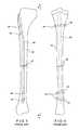
- FIGS. 3 and 4show another prior art solution involving an unreamed tibial nail 40 (shown in dashed line).
- the nail 40is inserted into the medullary canal 22 of the tibia 10 , medial to the patellar tendon and as superior as possible.
- the nail 40includes a plurality of openings 42 for receiving screws 44 . Once in position, the location of the openings 42 are determined by fluoroscopy and the screws 44 are inserted transversely through the bone and openings 42 for anchoring the nail 40 in place.
- this type of systemmay be acceptable for bones having relatively large cross sections, it is difficult to implement in smaller bone structures due to size restraints. This is especially typical pediatric cases.
- a typical nailmay have a diameter in the range of 8-9 mm and the screws may have a thread diameter of approximately 4 mm in order to properly secure the nail to the bone.
- a suitable nailmay have a diameter in the range of 2-4 mm and thus would require a screw with a substantially smaller thread diameter.
- forming a hole in the 2-4 mm nailwould be quite difficult, and the provision of a substantially smaller screw to fit in the hole would not provide sufficient cross-pinning to isolate movement of the nail or to fix it in a desired position.
- a screw assemblyfor securing an intramedullary rod in a medullary canal of a bone.
- the screw assemblyincludes a screw body with a shaft and at least one receiving bore that extends transversely through the shaft.
- the boreis adapted to receive an intramedullary rod.
- a securing memberis movable toward the bore to thereby secure the rod to the screw assembly.
- a system for securing an intramedullary rod in a medullary canal of a boneincludes an intramedullary rod and a screw assembly for receiving the rod.
- the screw assemblyhas a receiving bore extending transversely therethrough for receiving the intramedullary rod and a securing member movable toward the receiving bore for securing the rod to the screw assembly.
- An alignment jigmay also be provided for aligning the rod with the receiving bore during installation.
- a method for installing an intramedullary rod within a medullary canal of a bonecomprises providing a screw with a transverse bore, installing the screw into the bone such that the transverse bore is within the medullary canal, and inserting an intramedullary rod into the medullary canal and through the transverse bore. The intramedullary rod may then be secured to the screw.
- FIG. 1is a front elevational view of a prior art intramedullary nailing system for affixing and mobilizing separated bone segments of a bone structure;
- FIG. 2is a front elevational view of a further prior art intramedullary nailing system
- FIG. 3is a front elevational view if yet a further prior art intramedullary nailing system
- FIG. 4is a side elevational view as viewed from section plane 4 - 4 of FIG. 3 ;
- FIG. 5is a front elevational view of an intramedullary nailing system in accordance with an exemplary embodiment of the present invention for affixing and/or mobilizing separated bone segments of a bone structure;
- FIG. 6is an enlarged front view of a portion of the nailing system of FIG. 5 showing a bone segment in cross section;
- FIG. 7is a side elevational view of the nailing system of FIG. 6 ;
- FIG. 8is a top plan view of the nailing system taken along section plane 8 - 8 of FIG. 6 ;
- FIG. 9is an exploded perspective view of the nailing system in accordance with the present invention.
- FIG. 10is a front elevational view of an alignment jig together with an installed bone screw for aligning an intramedullary rod with a transverse opening in the screw in accordance with the present invention
- FIG. 11is a view similar to FIG. 10 with the alignment device in proper position for boring a hole through the bone;
- FIG. 12is a view similar to FIG. 10 and illustrating insertion of the intramedullary rod through the bored hole in alignment with the bore of the screw;
- FIG. 13is a front elevational view of an alignment jig in accordance with a further embodiment of the invention in proper position for boring a hole through the bone;
- FIG. 14is a view similar to FIG. 13 and illustrating insertion of the intramedullary rod through the bored hole and screws;
- FIG. 15is an enlarged front view of a nailing system in accordance with a further embodiment of the invention.
- an intramedullary nailing system 100in accordance with an exemplary embodiment of the present invention for affixing and/or mobilizing two or more separated bone segments, such as segments 114 , 116 , and 118 , of a bone structure 106 is illustrated.
- the system 100preferably includes an intramedullary nail or rod 102 (shown in hidden line) that is adapted to extend into the medullary canal 104 (also shown in hidden line) of the bone structure 106 with one or more fractures 108 , 110 and a screw assembly 112 that anchors the rod 102 within the medullary canal to secure the bone segments together during the treatment process.
- the system 100 of the present inventionis especially suitable in pediatric orthopedics for fixation of fractured bones such as the tibia, femur and humerus, complications caused by osteogenesis imperfecta, pseudoarthrosis of the tibia, and so on.
- the present inventionis not limited to treatment of the afore-mentioned bones for the afore-mentioned conditions, but is also applicable to a wide variety of bone structures (such as the fibula, ulna and radius), bone sizes and conditions for both pediatric and general orthopedics.
- the intramedullary rod 102is preferably of conventional construction and can be formed of various materials, such as titanium or stainless steel.
- the rod 102is also preferably circular in cross section, and of a sufficiently small diameter to fit within the medullary canal of the particular bone structure to be treated.
- rods with diameters of 2, 2.5, 3, and 4 mmare commonly used for pediatric applications.
- the intramedullary rod 102is not limited to the particular sizes, cross sectional shape or materials mentioned above, but may be constructed of different sizes, different cross sectional shapes such as square, triangular, oval, and so on, and different materials such as metals, ceramics, plastics, composites, or combinations thereof.
- the screw assembly 112preferably includes a screw body 120 with a locking member 122 positionable within an internal cavity 130 of the screw body for fixing the rod 102 to the screw assembly 112 .
- the screw body 120has a shaft 126 with a head portion 124 formed at one end thereof and an auger portion 128 formed at an opposite end.
- the shaft 126includes a transversely extending receiving bore 134 and the longitudinally extending internal cavity 130 that substantially coincides with a central axis 132 of the shaft and that intersects the internal cavity.
- a central axis 135 of the receiving bore 134 and the central axis 132 of the shaft 126are substantially perpendicular to each other.
- the internal cavity 130is preferably internally threaded for receiving and engaging the locking member 122 .
- the receiving bore 134can have a smooth inner surface and is sized to receive the intramedullary rod 102 .
- the head portion 124preferably has a generally flat front surface 136 and a curved rear surface 138 that extends between the front surface 136 and the shaft 126 .
- the diameter of the head portion 124is approximately 1.5 times the diameter of the shaft 126 .
- a hexagonally-shaped depression 140extends into the head portion 124 from the front surface 136 and intersects with the front end of the internal cavity 130 .
- the depression 140is adapted to receive a corresponding suitably shaped or hexagonally-shaped tool (not shown) for turning the screw assembly 112 during installation and removal as well as for alignment purposes, as will be described in greater detail below.
- Alignment indicator marks 142are formed in the front surface 136 of the head portion 124 at opposite sides of the depression 140 .
- the slots 142are preferably parallel with the central axis 135 of the receiving bore 134 so that the bore can be properly oriented during installation of the screw assembly 112 .
- the slots 142can be replaced with other marks, ticks, protrusions, or any other visually distinguishable indicating means for specifying the orientation of the receiving bore 134 .
- the head portion 124including the depression 140 , is not limited to the particular shape as shown and described, but may assume a wide variety of shapes and tool engaging configurations.
- the auger portion 128includes a conical section 144 with a spiral thread 146 that gradually diminishes in thread diameter toward the tip 148 to form a self-tapping configuration that facilitates boring into the bone structure as well as attachment of the screw assembly to the bone structure during installation. It will be understood that the auger portion 128 is not limited to the conical shape, but may alternatively be cylindrical with a uniform screw thread diameter or of any other suitable configuration.
- the locking member 122is preferably in the form of a set screw with outer threads 150 that engage the inner threads of the internal cavity 130 .
- a hexagonally-shaped, for example, depression 152is formed in an end face 154 of the locking member 122 .
- the depression 152is adapted to receive a corresponding or hexagonally-shaped tool (not shown) for turning the locking member 122 inside the internal cavity 130 toward or away from the receiving bore 134 to thereby clamp or release the intramedullary rod 10 within the receiving bore.
- the alignment jig 160includes a base member 162 with a first leg 164 and a second leg 166 that extends upwardly from the first leg.
- the first and second legsare substantially perpendicular to each other.
- a hexagonally-shaped, for example, bar 168is pivotally connected to an outer free end of the second leg 166 at a pivot joint 170 .
- the bar 168is sized and shaped to be received within the respective or hexagonal depression 140 of the screw head portion 120 .
- a tubular guide member 172extends downwardly from the first leg 164 and includes a central bore 174 (shown in hidden line) that substantially coincides with an opening 176 (shown in hidden lines) in the first leg 164 .
- a proximal surface 178 of the first leg 164is planar.
- the distance between a centerline of the central bore 174 and an inner surface 175 of the second leg 166 (or outer end of the hexagonal bar 168 )is preferably chosen so that when the alignment jig 160 is in the position shown in FIG. 11 , the central bore 174 will be aligned with the medullary canal of the bone and the receiving bore 134 of the screw assembly 112 .
- the particular number of screw assemblies 112 and their location along the length of the bone structure 106can be determined by fluoroscopy or other techniques, and may be based on the type and size of the bone structure, the age of the injured person, the number of breaks, and so on.
- the screw assemblies 112can then be installed at the determined locations by directly boring through the bone with the screw assemblies with an appropriate tool, such as a hex key connected to the chuck of a drill (not shown) or the like. In some circumstances, it may be desirable to drill pilot holes prior to transverse installation of the screw assemblies in the bone structure.
- the screw assembly 112is rotated until the alignment indicator slots 142 are aligned with the longitudinal direction of the bone structure 106 such that the receiving bore 134 is centered in the medullary canal 104 and also in alignment with the longitudinal direction of the bone structure, as shown in FIG. 8 . Since the receiving bore 134 is within the bone structure 106 , it may be difficult to view and align the receiving bore using fluoroscopy only. Accordingly, the alignment indicator slots 142 facilitate blind alignment of the first receiving 134 in the medullary canal.
- the hex rod 168 of the alignment jigis inserted into the hexagonal depression 140 .
- the base member 162is then rotated about the pivot joint 170 until the proximal surface 178 of the first leg 164 is in contact with the distal end 180 of the bone structure 106 .
- the exposed end of the hex rod 168is in contact with the inner surface 175 of the second leg 166 .
- the hex rod 168is preferably substantially perpendicular to the second leg 166 and parallel to the first leg 164 , as shown in FIGS. 11 and 12 .
- the central bore 174 of the tubular guide member 172is thus automatically aligned with the central axis 135 of the receiving bore 134 of the screw assembly 112 .
- a drill bit 182(shown in hidden line) is then inserted through the central bore 174 and the opening 176 .
- the drill bit 182Upon rotation by a rotary tool 184 , such as a drill or the like, the drill bit 182 forms a hole 186 in the distal end 180 of the bone structure 106 . It will be understood that the hole may additionally or alternatively be formed at the proximal end of the bone structure.
- the drill bitis removed and an intramedullary rod 102 is inserted through the central bore 174 , the opening 176 , the hole 186 , the medullary canal 104 (see FIGS. 6 and 12 ), and finally the receiving bore 134 of the screw assembly 112 .
- FIGS. 13 and 14When multiple screw assemblies are to be placed at different positions along the length of the bone, a plurality of alignment jigs with different leg sizes and guide member positions can be used, as illustrated in FIGS. 13 and 14 .
- the alignment jig 160 A as shownis substantially similar in construction to the alignment jig 160 previously described, with the exception that the second arm 166 A is shorter than the second arm 166 , and the position of the tubular guide member 172 and opening 176 are at a different location on the first leg 164 A to accommodate the extra width of the distal end 180 of the bone structure 106 .
- the embodiment of FIGS. 13 and 14is specifically adapted to accommodate bone growth of a patient.
- first leg 164 and/or the second leg 166may be telescopic or otherwise adjustable in length for adapting to any bone size and screw assembly placement. In this manner, a single alignment jig can be used for a variety of different alignment requirements.
- the rod 102is inserted through the receiving bore of each screw assembly as shown in FIG. 5 .
- the particular position of the rod 102 with respect to the screw assemblies 112can be verified through radiographic studies.
- the alignment jig 160is then removed and the locking member 122 of each screw assembly is rotated until the rod 102 is clamped between the locking member 122 and the inner wall of the receiving bore 134 (see FIG. 8 ).
- the intramedullary rodis securely fixed to the bone segments.
- one or more of the screw assembliesmay be left unclamped to provide for bone movement.
- a screw assembly 112 in accordance with the present invention with a shaft diameter of 5 mmcan be fixedly attached to a 2 mm diameter rod.
- a screw assembly 112 with a shaft diameter of 6 mmcan be fixedly attached to a 3 mm diameter rod, and so on.
- the particular sizes of screw assemblies and rod diameterscan be adjusted to accommodate a wide variety of bone structures and conditions.
- the relatively large diameter of the screw assembly 112enables it to span the medullary canal 104 and be securely fastened to opposite sides of a bone structure and to the intramedullary rod to thereby securely hold the bone segments together.
- the present inventionmay be used in treatments involving both compression and non-compression modes.
- the compression modewould include fixing the intramedullary rod at multiple positions for maximum bone stability that in many cases may allow at least partial weight bearing on the affected limb.
- the non-compression modewould include fixing the intramedullary rod at a single position (or even no fixation at all) to the screw assembly while allowing longitudinal guided motion of the rod through the receiving bore of a second screw assembly.
- the receiving borewould thus serve as a guide to ensure only linear movement of the rod during bone growth or treatment procedures.
- FIG. 15an intramedullary nailing system 200 in accordance with a further embodiment of the invention is illustrated.
- the system 200is similar in construction to the system 100 previously described, with the exception that two intramedullary nails or rods 102 A, 102 B are secured within a medullary canal 104 of a bone structure 106 by a pair of screw assemblies 202 A and 202 B, respectively. As shown, the screw assemblies 202 A and 202 B extend through the bone structure 106 from opposite directions.
- Each screw assembly 202 A, 202 Bis similar in construction to the screw assembly 112 , with the exception that a second receiving bore 204 is provided in the shaft 126 A between the receiving bore 134 and the conical section 144 to accommodate the extra intramedullary rod.
- the second receiving bore 204is preferably parallel to the receiving bore 134 .
- the rod 102 Ais secured to the screw assembly 202 A in a manner previously described, and is adapted to slide freely through the screw assembly 202 B via the second receiving bore 204 .
- the rod 102 Bis secured to the screw assembly 202 B and is adapted to slide freely through the screw assembly 202 A via the bore 204 . As illustrated in FIG.
- the rod or nail 102 Ais secured within the receiving bore of the screw assembly 202 A.
- this rodcan slide freely within a second receiving bore 204 of the second screw assembly 202 B.
- the nail or rod 102 Bis fixedly positioned within the first receiving bore 134 of the screw assembly 202 B and can slide freely within the second receiving bore 204 of the screw assembly 202 A.
- Such arrangementcompensates for possible movement of one segment of the broken bone with respect to another bone segment, while assuring the required stability of the bone structure.
- orientation and/or positionas may be used throughout the specification, such as but not limited to: lateral, medial, longitudinal, inner, outer, front, rear, upwardly, downwardly, as well as their derivatives and equivalent terms, relate to relative rather than absolute orientations and/or positions.
Landscapes
- Health & Medical Sciences (AREA)
- Orthopedic Medicine & Surgery (AREA)
- Surgery (AREA)
- Life Sciences & Earth Sciences (AREA)
- Heart & Thoracic Surgery (AREA)
- Veterinary Medicine (AREA)
- Engineering & Computer Science (AREA)
- Biomedical Technology (AREA)
- Nuclear Medicine, Radiotherapy & Molecular Imaging (AREA)
- Medical Informatics (AREA)
- Molecular Biology (AREA)
- Animal Behavior & Ethology (AREA)
- General Health & Medical Sciences (AREA)
- Public Health (AREA)
- Neurology (AREA)
- Dentistry (AREA)
- Oral & Maxillofacial Surgery (AREA)
- Surgical Instruments (AREA)
Abstract
Description
Claims (5)
Priority Applications (1)
| Application Number | Priority Date | Filing Date | Title |
|---|---|---|---|
| US11/250,498US7785326B2 (en) | 2005-10-14 | 2005-10-14 | System for intramedullary rod fixation and method therefor |
Applications Claiming Priority (1)
| Application Number | Priority Date | Filing Date | Title |
|---|---|---|---|
| US11/250,498US7785326B2 (en) | 2005-10-14 | 2005-10-14 | System for intramedullary rod fixation and method therefor |
Publications (2)
| Publication Number | Publication Date |
|---|---|
| US20070100342A1 US20070100342A1 (en) | 2007-05-03 |
| US7785326B2true US7785326B2 (en) | 2010-08-31 |
Family
ID=37997481
Family Applications (1)
| Application Number | Title | Priority Date | Filing Date |
|---|---|---|---|
| US11/250,498Active2029-03-21US7785326B2 (en) | 2005-10-14 | 2005-10-14 | System for intramedullary rod fixation and method therefor |
Country Status (1)
| Country | Link |
|---|---|
| US (1) | US7785326B2 (en) |
Cited By (22)
| Publication number | Priority date | Publication date | Assignee | Title |
|---|---|---|---|---|
| US20100211118A1 (en)* | 2009-02-16 | 2010-08-19 | Stryker Trauma Ag | Bone screw and method of manufacturing same |
| US8303589B2 (en) | 2008-06-24 | 2012-11-06 | Extremity Medical Llc | Fixation system, an intramedullary fixation assembly and method of use |
| US8313487B2 (en) | 2008-06-24 | 2012-11-20 | Extremity Medical Llc | Fixation system, an intramedullary fixation assembly and method of use |
| US8328806B2 (en) | 2008-06-24 | 2012-12-11 | Extremity Medical, Llc | Fixation system, an intramedullary fixation assembly and method of use |
| US8343199B2 (en) | 2008-06-24 | 2013-01-01 | Extremity Medical, Llc | Intramedullary fixation screw, a fixation system, and method of fixation of the subtalar joint |
| US20130197518A1 (en)* | 2011-06-14 | 2013-08-01 | Amit Gupta | Intramedullary system for managing a bone fracture |
| US9017329B2 (en) | 2008-06-24 | 2015-04-28 | Extremity Medical, Llc | Intramedullary fixation assembly and method of use |
| US9044282B2 (en) | 2008-06-24 | 2015-06-02 | Extremity Medical Llc | Intraosseous intramedullary fixation assembly and method of use |
| US9289220B2 (en) | 2008-06-24 | 2016-03-22 | Extremity Medical Llc | Intramedullary fixation assembly and method of use |
| WO2018157170A1 (en)* | 2017-02-27 | 2018-08-30 | Paragon 28, Inc. | Targeting instruments, systems and methods of use |
| US10327829B2 (en) | 2012-12-28 | 2019-06-25 | Paragon 28, Inc. | Alignment guide apparatus, methods and systems |
| US10610241B2 (en) | 2016-10-24 | 2020-04-07 | Paragon 28, Inc. | Osteotomy systems, devices and methods |
| US10758280B2 (en) | 2017-10-09 | 2020-09-01 | Acumed Llc | System and method for bone fixation using a nail locked to an encircling anchor |
| US10799276B2 (en) | 2017-07-11 | 2020-10-13 | Paragon 28, Inc. | Bone fixation system, assembly, implants, devices, insertion guides, and methods of use |
| US10888338B2 (en) | 2017-02-27 | 2021-01-12 | Paragon 28, Inc. | Intramedullary nail alignment guides, fixation guides, devices, systems, and methods of use |
| US10918431B2 (en) | 2017-03-30 | 2021-02-16 | Paragon 28, Inc. | Bone fixation system, assembly, implants, devices, alignment guides, and methods of use |
| US11123120B2 (en) | 2018-07-11 | 2021-09-21 | Paragon 28, Inc. | Implants, alignment guides, systems and methods of use |
| WO2022076647A1 (en) | 2020-10-08 | 2022-04-14 | Acumed Llc | Devices and systems for nail-based bone fixation |
| US20220151664A1 (en)* | 2015-04-16 | 2022-05-19 | Texas Tech University System | Ankle (Tibio-Talar) Fusion Nail |
| US11925364B2 (en) | 2019-02-13 | 2024-03-12 | Paragon 28, Inc. | Implant, alignment guides, system and methods of use |
| US12076031B2 (en) | 2019-02-14 | 2024-09-03 | Paragon 28, Inc. | Threaded targeting instruments, systems and methods of use |
| US12171442B2 (en) | 2019-02-28 | 2024-12-24 | Paragon 28, Inc. | Fusion systems, instruments, bone plates and methods of use |
Families Citing this family (15)
| Publication number | Priority date | Publication date | Assignee | Title |
|---|---|---|---|---|
| AU2008256740A1 (en) | 2007-05-25 | 2008-12-04 | Zimmer, Gmbh | Reinforced intramedullary nail |
| US8206389B2 (en)* | 2007-08-31 | 2012-06-26 | Huebner Randall J | Rod-based system for bone fixation |
| ES2524076T3 (en) | 2008-10-15 | 2014-12-04 | Zimmer Gmbh | Intramedullary nail |
| CN102281829A (en)* | 2008-11-19 | 2011-12-14 | 安杜奥斯皮迪克公司 | Intramedullary repair system for bone fractures |
| WO2010059860A1 (en) | 2008-11-19 | 2010-05-27 | Endoorthopaedics, Inc. | Intramedullary repair system for bone fractures |
| US9028496B2 (en)* | 2011-04-12 | 2015-05-12 | William L. Tontz | Device for establishing supportive forces in the bony structure of a skeleton |
| US8551106B2 (en)* | 2011-09-30 | 2013-10-08 | Arthrocare Corporation | Method and apparatus for installation of intramedullary medical device |
| ES2656974T3 (en) | 2012-01-19 | 2018-03-01 | Stryker European Holdings I, Llc | Cuff for suprarrotulian surgery |
| WO2013123366A1 (en) | 2012-02-16 | 2013-08-22 | Paragon 28, Inc. | Charco-resis implant, alignment instrument, system and method of use |
| US9517094B1 (en)* | 2014-05-09 | 2016-12-13 | Savage Medical Design LLC | Intramedullary fixation apparatus for use in hip and femur fracture surgery |
| JP6811498B2 (en) | 2016-09-08 | 2021-01-13 | メダロック, エルエルシー | Implants and methods for long bone fixation |
| US10426529B2 (en) | 2017-07-05 | 2019-10-01 | Mark A. Barry | Surgical systems, kits and methods for setting bone segments |
| CN113143430A (en)* | 2020-01-22 | 2021-07-23 | 杨琳敏 | Humerus proximal elbow joint fracture reduction fixing method of interlocking intramedullary double-long steel bar |
| WO2023147064A1 (en)* | 2022-01-28 | 2023-08-03 | Forma Medical, Inc. | Bone fixation system and device |
| USD1081993S1 (en) | 2023-01-27 | 2025-07-01 | Forma Medical, Inc. | Bone fixation guide |
Citations (15)
| Publication number | Priority date | Publication date | Assignee | Title |
|---|---|---|---|---|
| US2168000A (en)* | 1935-10-29 | 1939-08-01 | Firm Bauer & Schurte Rheinisch | Screw or screw bolt |
| US2658508A (en)* | 1952-08-13 | 1953-11-10 | Robert B Gibson | Bone fracture splint |
| US4281649A (en)* | 1977-04-01 | 1981-08-04 | Joan Derweduwen | Osteosynthesis method and apparatus for reducing a bone fracture |
| US4622959A (en)* | 1985-03-05 | 1986-11-18 | Marcus Randall E | Multi-use femoral intramedullary nail |
| US4827917A (en)* | 1986-12-30 | 1989-05-09 | Richards Medical Company | Fermoral fracture device |
| US4875475A (en)* | 1984-11-30 | 1989-10-24 | Synthes (U.S.A.) | Device for treating a bone |
| US4976258A (en) | 1983-03-09 | 1990-12-11 | Howmedica International, Inc. | Locking nail |
| US5118236A (en)* | 1991-03-04 | 1992-06-02 | The United States Of America As Represented By The Secretary Of The Air Force | Floating center tapped shoulder screw |
| US5489284A (en)* | 1994-07-15 | 1996-02-06 | Smith & Nephew Richards Inc. | Cannulated modular intramedullary nail |
| US6221074B1 (en)* | 1999-06-10 | 2001-04-24 | Orthodyne, Inc. | Femoral intramedullary rod system |
| US6235031B1 (en)* | 2000-02-04 | 2001-05-22 | Encore Medical Corporation | Intramedullary fracture fixation device |
| US6270499B1 (en) | 1997-10-20 | 2001-08-07 | Synthes (U.S.A.) | Bone fixation device |
| US6379360B1 (en)* | 1998-03-11 | 2002-04-30 | Synthes (Usa) | Spiral blade insertion instrument |
| US6579293B1 (en) | 2000-08-02 | 2003-06-17 | Rama E. Chandran | Intramedullary rod with interlocking oblique screw for tibio-calcaneal arthrodesis |
| US7347861B2 (en)* | 2001-01-31 | 2008-03-25 | Grampian Health Board | Bone fixture apparatus and jig |
- 2005
- 2005-10-14USUS11/250,498patent/US7785326B2/enactiveActive
Patent Citations (16)
| Publication number | Priority date | Publication date | Assignee | Title |
|---|---|---|---|---|
| US2168000A (en)* | 1935-10-29 | 1939-08-01 | Firm Bauer & Schurte Rheinisch | Screw or screw bolt |
| US2658508A (en)* | 1952-08-13 | 1953-11-10 | Robert B Gibson | Bone fracture splint |
| US4281649A (en)* | 1977-04-01 | 1981-08-04 | Joan Derweduwen | Osteosynthesis method and apparatus for reducing a bone fracture |
| US4976258A (en) | 1983-03-09 | 1990-12-11 | Howmedica International, Inc. | Locking nail |
| US4875475A (en)* | 1984-11-30 | 1989-10-24 | Synthes (U.S.A.) | Device for treating a bone |
| US4622959A (en)* | 1985-03-05 | 1986-11-18 | Marcus Randall E | Multi-use femoral intramedullary nail |
| US4827917A (en)* | 1986-12-30 | 1989-05-09 | Richards Medical Company | Fermoral fracture device |
| US5118236A (en)* | 1991-03-04 | 1992-06-02 | The United States Of America As Represented By The Secretary Of The Air Force | Floating center tapped shoulder screw |
| US5489284A (en)* | 1994-07-15 | 1996-02-06 | Smith & Nephew Richards Inc. | Cannulated modular intramedullary nail |
| US6270499B1 (en) | 1997-10-20 | 2001-08-07 | Synthes (U.S.A.) | Bone fixation device |
| US6379360B1 (en)* | 1998-03-11 | 2002-04-30 | Synthes (Usa) | Spiral blade insertion instrument |
| US6221074B1 (en)* | 1999-06-10 | 2001-04-24 | Orthodyne, Inc. | Femoral intramedullary rod system |
| US6402753B1 (en) | 1999-06-10 | 2002-06-11 | Orthodyne, Inc. | Femoral intramedullary rod system |
| US6235031B1 (en)* | 2000-02-04 | 2001-05-22 | Encore Medical Corporation | Intramedullary fracture fixation device |
| US6579293B1 (en) | 2000-08-02 | 2003-06-17 | Rama E. Chandran | Intramedullary rod with interlocking oblique screw for tibio-calcaneal arthrodesis |
| US7347861B2 (en)* | 2001-01-31 | 2008-03-25 | Grampian Health Board | Bone fixture apparatus and jig |
Non-Patent Citations (2)
| Title |
|---|
| The AO/ASIF Unreamed Tibial Nail, SYNTHES, 1992. |
| The Titanium Elastic Nail System (Technique Guide), SYNTHES, 1998. |
Cited By (44)
| Publication number | Priority date | Publication date | Assignee | Title |
|---|---|---|---|---|
| US9289220B2 (en) | 2008-06-24 | 2016-03-22 | Extremity Medical Llc | Intramedullary fixation assembly and method of use |
| US11974786B2 (en) | 2008-06-24 | 2024-05-07 | Extremity Medical L.L.C. | Intraosseous intramedullary fixation assembly and method of use |
| US8313487B2 (en) | 2008-06-24 | 2012-11-20 | Extremity Medical Llc | Fixation system, an intramedullary fixation assembly and method of use |
| US8328806B2 (en) | 2008-06-24 | 2012-12-11 | Extremity Medical, Llc | Fixation system, an intramedullary fixation assembly and method of use |
| US8343199B2 (en) | 2008-06-24 | 2013-01-01 | Extremity Medical, Llc | Intramedullary fixation screw, a fixation system, and method of fixation of the subtalar joint |
| US11298166B2 (en) | 2008-06-24 | 2022-04-12 | Extremity Medical Llc | Intraosseous intramedullary fixation assembly and method of use |
| US8900274B2 (en) | 2008-06-24 | 2014-12-02 | Extremity Medical Llc | Fixation system, an intramedullary fixation assembly and method of use |
| US8920453B2 (en) | 2008-06-24 | 2014-12-30 | Extremity Medical, Llc | Fixation system, an intramedullary fixation assembly and method of use |
| US8920476B2 (en) | 2008-06-24 | 2014-12-30 | Extremity Medical, Llc | Fixation system, an intramedullary fixation assembly and method of use |
| US10751097B2 (en) | 2008-06-24 | 2020-08-25 | Extremity Medical Llc | Intraosseous intramedullary fixation assembly and method of use |
| US9017329B2 (en) | 2008-06-24 | 2015-04-28 | Extremity Medical, Llc | Intramedullary fixation assembly and method of use |
| US9044282B2 (en) | 2008-06-24 | 2015-06-02 | Extremity Medical Llc | Intraosseous intramedullary fixation assembly and method of use |
| US8303589B2 (en) | 2008-06-24 | 2012-11-06 | Extremity Medical Llc | Fixation system, an intramedullary fixation assembly and method of use |
| US20100211118A1 (en)* | 2009-02-16 | 2010-08-19 | Stryker Trauma Ag | Bone screw and method of manufacturing same |
| US8992528B2 (en)* | 2011-06-14 | 2015-03-31 | Amit Gupta | Intramedullary system for managing a bone fracture |
| US20130197518A1 (en)* | 2011-06-14 | 2013-08-01 | Amit Gupta | Intramedullary system for managing a bone fracture |
| USD1045639S1 (en) | 2012-12-28 | 2024-10-08 | Paragon 28, Inc. | Alignment guide |
| US10327829B2 (en) | 2012-12-28 | 2019-06-25 | Paragon 28, Inc. | Alignment guide apparatus, methods and systems |
| US11779382B2 (en) | 2012-12-28 | 2023-10-10 | Paragon 28, Inc. | Alignment guide apparatus, methods and systems |
| US12295633B2 (en) | 2012-12-28 | 2025-05-13 | Paragon 28, Inc. | Alignment guide apparatus, methods and systems |
| US11395691B2 (en) | 2012-12-28 | 2022-07-26 | Paragon 28, Inc. | Alignment guide apparatus, methods and systems |
| US20220151664A1 (en)* | 2015-04-16 | 2022-05-19 | Texas Tech University System | Ankle (Tibio-Talar) Fusion Nail |
| US11642142B2 (en) | 2016-10-24 | 2023-05-09 | Paragon 28, Inc. | Osteotomy systems, devices and methods |
| US10610241B2 (en) | 2016-10-24 | 2020-04-07 | Paragon 28, Inc. | Osteotomy systems, devices and methods |
| US12185953B2 (en) | 2016-10-24 | 2025-01-07 | Paragon 28, Inc. | Osteotomy systems, devices and methods |
| US11179168B2 (en) | 2017-02-27 | 2021-11-23 | Paragon 28, Inc. | Targeting instruments, systems and methods of use |
| US11779358B2 (en) | 2017-02-27 | 2023-10-10 | Paragon 28, Inc. | Targeting instruments, systems and methods of use |
| US12178454B2 (en) | 2017-02-27 | 2024-12-31 | Paragon 28, Inc. | Targeting instruments, systems and methods of use |
| WO2018157170A1 (en)* | 2017-02-27 | 2018-08-30 | Paragon 28, Inc. | Targeting instruments, systems and methods of use |
| US11666345B2 (en) | 2017-02-27 | 2023-06-06 | Paragon 28, Inc. | Intramedullary nail alignment guides, fixation guides, devices, systems, and methods of use |
| US12396768B2 (en) | 2017-02-27 | 2025-08-26 | Paragon 28, Inc. | Intramedullary nail alignment guides, fixation guides, devices, systems, and methods of use |
| US10888338B2 (en) | 2017-02-27 | 2021-01-12 | Paragon 28, Inc. | Intramedullary nail alignment guides, fixation guides, devices, systems, and methods of use |
| US12295634B2 (en) | 2017-03-30 | 2025-05-13 | Paragon 28, Inc. | Bone fixation system, assembly, implants, devices, alignment guides, and methods of use |
| US10918431B2 (en) | 2017-03-30 | 2021-02-16 | Paragon 28, Inc. | Bone fixation system, assembly, implants, devices, alignment guides, and methods of use |
| US10799276B2 (en) | 2017-07-11 | 2020-10-13 | Paragon 28, Inc. | Bone fixation system, assembly, implants, devices, insertion guides, and methods of use |
| US11559316B2 (en) | 2017-07-11 | 2023-01-24 | Paragon 28, Inc. | Bone fixation system, assembly, implants, devices, insertion guides, and methods of use |
| EP4321117A2 (en) | 2017-10-09 | 2024-02-14 | Acumed LLC | System for bone fixation using a nail locked to an encircling anchor |
| US10758280B2 (en) | 2017-10-09 | 2020-09-01 | Acumed Llc | System and method for bone fixation using a nail locked to an encircling anchor |
| US11123120B2 (en) | 2018-07-11 | 2021-09-21 | Paragon 28, Inc. | Implants, alignment guides, systems and methods of use |
| US11925364B2 (en) | 2019-02-13 | 2024-03-12 | Paragon 28, Inc. | Implant, alignment guides, system and methods of use |
| US12076031B2 (en) | 2019-02-14 | 2024-09-03 | Paragon 28, Inc. | Threaded targeting instruments, systems and methods of use |
| US12171442B2 (en) | 2019-02-28 | 2024-12-24 | Paragon 28, Inc. | Fusion systems, instruments, bone plates and methods of use |
| WO2022076647A1 (en) | 2020-10-08 | 2022-04-14 | Acumed Llc | Devices and systems for nail-based bone fixation |
| US11751889B2 (en) | 2020-10-08 | 2023-09-12 | Acumed Llc | Devices and systems for nail-based bone fixation |
Also Published As
| Publication number | Publication date |
|---|---|
| US20070100342A1 (en) | 2007-05-03 |
Similar Documents
| Publication | Publication Date | Title |
|---|---|---|
| US7785326B2 (en) | System for intramedullary rod fixation and method therefor | |
| EP2938279B1 (en) | Alignment guide system | |
| CA2622379C (en) | Orthopedic implant insertion handle and aiming guide | |
| EP1976442B1 (en) | Assemblies for the reduction of a fracture | |
| JP4913067B2 (en) | Intraosseous nail | |
| US8740903B2 (en) | Method and apparatus for bone fracture fixation | |
| US4913137A (en) | Intramedullary rod system | |
| EP2713918B1 (en) | Assemblies for aligning a bone fixation plate | |
| US7927333B2 (en) | System for the minimally invasive treatment of a bone fracture, especially of a proximal humeral or femoral fracture | |
| US20110137356A1 (en) | Bone compression device and methods | |
| US7347861B2 (en) | Bone fixture apparatus and jig | |
| JPH10501438A (en) | Intramedullary nail | |
| EP2175790A2 (en) | A bolt apparatus | |
| US11925364B2 (en) | Implant, alignment guides, system and methods of use | |
| US20100094291A1 (en) | Clamp For A Medical Implant And A Method For Using The Same | |
| US10966735B1 (en) | Surgical device and method for performing arthrodesis | |
| GB2401053A (en) | An apparatus to facilitate locking of intramedullary fixation devices using radiographic visualisation | |
| CN119074187A (en) | Improved intramedullary nail, auxiliary nail placement device and nail placement method | |
| WO2023086579A1 (en) | Interlocking screws for orthopedic surgery | |
| AU2013263822B2 (en) | Assemblies for the reduction of a fracture |
Legal Events
| Date | Code | Title | Description |
|---|---|---|---|
| STCF | Information on status: patent grant | Free format text:PATENTED CASE | |
| FPAY | Fee payment | Year of fee payment:4 | |
| MAFP | Maintenance fee payment | Free format text:PAYMENT OF MAINTENANCE FEE, 8TH YR, SMALL ENTITY (ORIGINAL EVENT CODE: M2552) Year of fee payment:8 | |
| MAFP | Maintenance fee payment | Free format text:PAYMENT OF MAINTENANCE FEE, 12TH YR, SMALL ENTITY (ORIGINAL EVENT CODE: M2553); ENTITY STATUS OF PATENT OWNER: SMALL ENTITY Year of fee payment:12 | |
| AS | Assignment | Owner name:PEGA MEDICAL, INC, CANADA Free format text:ASSIGNMENT OF ASSIGNORS INTEREST;ASSIGNORS:GREEN, DANIEL W.;MOLINO, JOSEPH L.;SIGNING DATES FROM 20220524 TO 20220526;REEL/FRAME:060059/0282 | |
| AS | Assignment | Owner name:SQUADRON CAPITAL LLC, CONNECTICUT Free format text:SECURITY INTEREST;ASSIGNOR:ORTHOPEDIATRICS CANADA ULC;REEL/FRAME:062092/0175 Effective date:20220115 | |
| AS | Assignment | Owner name:ORTHOPEDIATRICS CORP., INDIANA Free format text:RELEASE BY SECURED PARTY;ASSIGNOR:SQUADRON CAPITAL LLC;REEL/FRAME:066378/0863 Effective date:20231229 | |
| AS | Assignment | Owner name:MIDCAP FUNDING IV TRUST, MARYLAND Free format text:SECURITY INTEREST;ASSIGNOR:ORTHOPEDIATRICS CANADA ULC;REEL/FRAME:068245/0082 Effective date:20240614 | |
| AS | Assignment | Owner name:ORTHOPEDIATRICS CANADA ULC, CANADA Free format text:RELEASE BY SECURED PARTY;ASSIGNOR:MIDCAP FUNDING IV TRUST;REEL/FRAME:068269/0295 Effective date:20240812 |