US7785323B2 - Loop structure including inflatable therapeutic device - Google Patents
Loop structure including inflatable therapeutic deviceDownload PDFInfo
- Publication number
- US7785323B2 US7785323B2US09/730,010US73001000AUS7785323B2US 7785323 B2US7785323 B2US 7785323B2US 73001000 AUS73001000 AUS 73001000AUS 7785323 B2US7785323 B2US 7785323B2
- Authority
- US
- United States
- Prior art keywords
- probe
- distal
- proximal
- tissue coagulation
- loop
- Prior art date
- Legal status (The legal status is an assumption and is not a legal conclusion. Google has not performed a legal analysis and makes no representation as to the accuracy of the status listed.)
- Active, expires
Links
Images


Classifications
- A—HUMAN NECESSITIES
- A61—MEDICAL OR VETERINARY SCIENCE; HYGIENE
- A61B—DIAGNOSIS; SURGERY; IDENTIFICATION
- A61B18/00—Surgical instruments, devices or methods for transferring non-mechanical forms of energy to or from the body
- A61B18/04—Surgical instruments, devices or methods for transferring non-mechanical forms of energy to or from the body by heating
- A61B18/12—Surgical instruments, devices or methods for transferring non-mechanical forms of energy to or from the body by heating by passing a current through the tissue to be heated, e.g. high-frequency current
- A61B18/14—Probes or electrodes therefor
- A61B18/1492—Probes or electrodes therefor having a flexible, catheter-like structure, e.g. for heart ablation
- A—HUMAN NECESSITIES
- A61—MEDICAL OR VETERINARY SCIENCE; HYGIENE
- A61B—DIAGNOSIS; SURGERY; IDENTIFICATION
- A61B18/00—Surgical instruments, devices or methods for transferring non-mechanical forms of energy to or from the body
- A61B2018/00053—Mechanical features of the instrument of device
- A61B2018/00059—Material properties
- A61B2018/00065—Material properties porous
- A—HUMAN NECESSITIES
- A61—MEDICAL OR VETERINARY SCIENCE; HYGIENE
- A61B—DIAGNOSIS; SURGERY; IDENTIFICATION
- A61B18/00—Surgical instruments, devices or methods for transferring non-mechanical forms of energy to or from the body
- A61B2018/00053—Mechanical features of the instrument of device
- A61B2018/00214—Expandable means emitting energy, e.g. by elements carried thereon
- A61B2018/0022—Balloons
- A61B2018/00226—Balloons extending from a surface, i.e. Blisters
- A—HUMAN NECESSITIES
- A61—MEDICAL OR VETERINARY SCIENCE; HYGIENE
- A61B—DIAGNOSIS; SURGERY; IDENTIFICATION
- A61B18/00—Surgical instruments, devices or methods for transferring non-mechanical forms of energy to or from the body
- A61B2018/00053—Mechanical features of the instrument of device
- A61B2018/00214—Expandable means emitting energy, e.g. by elements carried thereon
- A61B2018/0022—Balloons
- A61B2018/00238—Balloons porous
- A—HUMAN NECESSITIES
- A61—MEDICAL OR VETERINARY SCIENCE; HYGIENE
- A61B—DIAGNOSIS; SURGERY; IDENTIFICATION
- A61B18/00—Surgical instruments, devices or methods for transferring non-mechanical forms of energy to or from the body
- A61B2018/00315—Surgical instruments, devices or methods for transferring non-mechanical forms of energy to or from the body for treatment of particular body parts
- A61B2018/00345—Vascular system
- A61B2018/00351—Heart
- A61B2018/00375—Ostium, e.g. ostium of pulmonary vein or artery
- A—HUMAN NECESSITIES
- A61—MEDICAL OR VETERINARY SCIENCE; HYGIENE
- A61B—DIAGNOSIS; SURGERY; IDENTIFICATION
- A61B18/00—Surgical instruments, devices or methods for transferring non-mechanical forms of energy to or from the body
- A61B2018/00636—Sensing and controlling the application of energy
- A61B2018/00898—Alarms or notifications created in response to an abnormal condition
- A—HUMAN NECESSITIES
- A61—MEDICAL OR VETERINARY SCIENCE; HYGIENE
- A61B—DIAGNOSIS; SURGERY; IDENTIFICATION
- A61B18/00—Surgical instruments, devices or methods for transferring non-mechanical forms of energy to or from the body
- A61B18/04—Surgical instruments, devices or methods for transferring non-mechanical forms of energy to or from the body by heating
- A61B18/12—Surgical instruments, devices or methods for transferring non-mechanical forms of energy to or from the body by heating by passing a current through the tissue to be heated, e.g. high-frequency current
- A61B18/1206—Generators therefor
- A61B2018/1246—Generators therefor characterised by the output polarity
- A61B2018/1253—Generators therefor characterised by the output polarity monopolar
- A—HUMAN NECESSITIES
- A61—MEDICAL OR VETERINARY SCIENCE; HYGIENE
- A61B—DIAGNOSIS; SURGERY; IDENTIFICATION
- A61B18/00—Surgical instruments, devices or methods for transferring non-mechanical forms of energy to or from the body
- A61B18/04—Surgical instruments, devices or methods for transferring non-mechanical forms of energy to or from the body by heating
- A61B18/12—Surgical instruments, devices or methods for transferring non-mechanical forms of energy to or from the body by heating by passing a current through the tissue to be heated, e.g. high-frequency current
- A61B18/1206—Generators therefor
- A61B2018/1246—Generators therefor characterised by the output polarity
- A61B2018/126—Generators therefor characterised by the output polarity bipolar
- A—HUMAN NECESSITIES
- A61—MEDICAL OR VETERINARY SCIENCE; HYGIENE
- A61B—DIAGNOSIS; SURGERY; IDENTIFICATION
- A61B18/00—Surgical instruments, devices or methods for transferring non-mechanical forms of energy to or from the body
- A61B18/04—Surgical instruments, devices or methods for transferring non-mechanical forms of energy to or from the body by heating
- A61B18/12—Surgical instruments, devices or methods for transferring non-mechanical forms of energy to or from the body by heating by passing a current through the tissue to be heated, e.g. high-frequency current
- A61B18/14—Probes or electrodes therefor
- A61B2018/1405—Electrodes having a specific shape
- A61B2018/1407—Loop
- A—HUMAN NECESSITIES
- A61—MEDICAL OR VETERINARY SCIENCE; HYGIENE
- A61B—DIAGNOSIS; SURGERY; IDENTIFICATION
- A61B18/00—Surgical instruments, devices or methods for transferring non-mechanical forms of energy to or from the body
- A61B18/04—Surgical instruments, devices or methods for transferring non-mechanical forms of energy to or from the body by heating
- A61B18/12—Surgical instruments, devices or methods for transferring non-mechanical forms of energy to or from the body by heating by passing a current through the tissue to be heated, e.g. high-frequency current
- A61B18/14—Probes or electrodes therefor
- A61B2018/1472—Probes or electrodes therefor for use with liquid electrolyte, e.g. virtual electrodes
Definitions
- the present inventionsrelate generally to medical devices that support therapeutic elements in contact with body tissue and, more particularly, to loop structures that support therapeutic elements in contact with bodily tissue.
- arrhythmiaThere are many instances where diagnostic and therapeutic elements must be inserted into the body.
- One instanceinvolves the treatment of cardiac conditions such as atrial fibrillation and atrial flutter which lead to an unpleasant, irregular heart beat, called arrhythmia.
- SA nodesinoatrial node
- AV nodeatrioventricular node
- This propagationcauses the atria to contract in an organized way to transport blood from the atria to the ventricles, and to provide timed stimulation of the ventricles.
- the AV noderegulates the propagation delay to the atrioventricular bundle (or “HIS” bundle).
- HISatrioventricular bundle
- Atrial fibrillationoccurs when anatomical obstacles in the heart disrupt the normally uniform propagation of electrical impulses in the atria. These anatomical obstacles (called “conduction blocks”) can cause the electrical impulse to degenerate into several circular wavelets that circulate about the obstacles. These wavelets, called “reentry circuits,” disrupt the normally uniform activation of the left and right atria.
- maze procedureOne surgical method of treating atrial fibrillation by interrupting pathways for reentry circuits is the so-called “maze procedure” which relies on a prescribed pattern of incisions to anatomically create a convoluted path, or maze, for electrical propagation within the left and right atria.
- the incisionsdirect the electrical impulse from the SA node along a specified route through all regions of both atria, causing uniform contraction required for normal atrial transport function.
- the incisionsfinally direct the impulse to the AV node to activate the ventricles, restoring normal atrioventricular synchrony.
- the incisionsare also carefully placed to interrupt the conduction routes of the most common reentry circuits.
- the maze procedurehas been found very effective in curing atrial fibrillation. However, the maze procedure is technically difficult to do. It also requires open heart surgery and is very expensive.
- Catheters used to create lesionstypically include a relatively long and relatively flexible body portion that has a soft tissue coagulation electrode on its distal end and/or a series of spaced tissue coagulation electrodes near the distal end.
- the portion of the catheter body portion that is inserted into the patientis typically from 23 to 55 inches in length and there may be another 8 to 15 inches, including a handle, outside the patient.
- the length and flexibility of the catheter bodyallow the catheter to be inserted into a main vein or artery (typically the femoral artery), directed into the interior of the heart, and then manipulated such that the coagulation electrode contacts the tissue that is to be ablated. Fluoroscopic imaging is used to provide the physician with a visual indication of the location of the catheter.
- the proximal end of the catheter bodyis connected to a handle that includes steering controls.
- Exemplary catheters of this typeare disclosed in U.S. Pat. No. 5,582,609.
- the catheter bodyis inserted into the patient through a sheath and the distal portion of the catheter is bent into loop that extends outwardly from the sheath. This may be accomplished by pivotably securing the distal end of the catheter to the distal end of the sheath, as is illustrated U.S. Pat. No. 6,071,279.
- the loopis formed as the catheter is pushed in the distal direction.
- the loopmay also be formed by securing a pull wire to the distal end of the catheter that extends back through the sheath, as is illustrated in U.S. Pat. No. 6,048,329.
- Loop cathetersare advantageous in that they tend to conform to different tissue contours and geometries and provide intimate contact between the spaced tissue coagulation electrodes (or other diagnostic or therapeutic elements) and the tissue.
- lesionsthat are used to isolate the pulmonary vein and cure ectopic atrial fibrillation. Lesions may be formed within the pulmonary vein itself or in the tissue surrounding the pulmonary vein (the “pulmonary vein ostium”) to isolate the pulmonary vein.
- pulmonary vein ostiumtissue surrounding the pulmonary vein
- Conventional steerable catheters and loop cathetershave proven to be less than effective with respect to the formation of such circumferential lesions. For example, it can be difficult to achieve the level of tissue contact required to form an effective lesion.
- inflatable lesion formation structureshave also been proposed. Depending on their size, such structures are typically inflated within the pulmonary vein or inflated and then advanced into contact with the pulmonary vein ostium. Such devices tend to establish better tissue contact than conventional steerable catheters and loop catheters. However, they also act as a plug and occlude the flow of blood through the pulmonary vein. In addition, the inventors herein have determined that it can be difficult to manufacture a balloon that will be large enough when inflated to engage the entire circumference of the pulmonary vein ostium, and small enough when deflated to be advanced through a sheath to the ostium.
- the inventors hereinhave determined that a need exists for structures that can be used to create effective lesions within or around the pulmonary vein without occluding blood flow.
- the general object of the present inventionsis to provide a device that avoids, for practical purposes, the aforementioned problems.
- one object of the present inventionsis to provide a device that can be used to create lesions in or around the pulmonary vein and other bodily orifices in a more effective manner than conventional apparatus.
- Another object of the present inventionis to provide a device that can be used to create lesions in or around the pulmonary vein and other bodily orifices with occluding the flow of blood or other body fluids.
- Still another object of the present inventionis to provide a device including an inflatable structure that can be used to create lesions in or around the pulmonary vein and is also small enough when deflated to be advanced through a sheath.
- a probe in accordance with one embodiment of a present inventionincludes an elongate body defining a distal region adapted to be bent into a loop and an inflatable tissue coagulation body supported on the elongate body distal region.
- the inflatable tissue coagulation bodywill be a half-balloon structure located on one side of the loop and spaced inwardly from the apex (or distal end) of the loop.
- the present probeprovides a number of advantages over conventional catheter devices.
- the present probeprovides superior tissue contact at the pulmonary vein ostium.
- the apex (or distal end) of the loop in the present probemay be inserted into the pulmonary vein to such an extent that the inflatable tissue coagulation body will be adjacent to the pulmonary vein ostium.
- Such positioningwill wedge the inflatable tissue coagulation body into close contact with the ostium and, when the tissue coagulation body is inflated, the level of contact will be increased.
- the tissue coagulation bodymay be deflated and the loop repositioned so that another lesion can be formed. This process will continue until a continuous circumferential lesion has been formed around the ostium.
- the present probeWhen the apex of the present probe is inserted into the pulmonary vein ostium, the present probe defines an open region that allows blood to pass therethrough. As a result, the present probe facilitates the formation of a circumferential lesion without the occlusion of blood associated with conventional inflatable lesion formation structures.
- FIG. 1is a side view of a catheter-based probe in accordance with a preferred embodiment of a present invention.
- FIG. 2is an enlarged view of the distal portion of the probe illustrated in FIG. 1 .
- FIG. 3is an end view of the distal portion of the probe illustrated in FIG. 1 .
- FIG. 4is a top view of the distal portion of the probe illustrated in FIG. 1 .
- FIG. 5is a top cutaway view of the distal portion of the probe illustrated in FIG. 1 .
- FIG. 6is a section view taken along line 6 - 6 in FIG. 4 .
- FIG. 7is a section view in accordance with another preferred embodiment of a present invention.
- FIG. 8is a side view of an expandable tissue heating structure in accordance with another preferred embodiment of a present invention.
- FIG. 9is a side view of the distal portion of a catheter-based probe in accordance with another preferred embodiment of a present invention.
- FIG. 10is a section view taken along line 10 - 10 in FIG. 9 .
- FIG. 11is a section view in accordance with another preferred embodiment of a present invention.
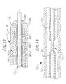
- FIG. 12is a partial section view of the tip region of the probe illustrated in FIG. 1 .
- FIG. 13is a partial section view of the hinge region of the probe illustrated in FIG. 1 .
- FIG. 14is a side view of the distal portion of a catheter-based probe in accordance with another preferred embodiment of a present invention.
- FIG. 15is a side view of the tip region of a catheter-based probe in accordance with yet another preferred embodiment of a present invention.
- FIG. 16 ais a side view showing the probe illustrated in FIG. 1 positioned adjacent the pulmonary vein ostium with the expandable electrode in a collapsed state.
- FIG. 16 bis a side view showing the probe illustrated in FIG. 1 positioned adjacent the pulmonary vein ostium with the expandable electrode in an expanded state.
- the present inventionsmay be used within body lumens, chambers or cavities for diagnostic or therapeutic purposes in those instance where access to interior bodily regions is obtained through, for example, the vascular system or alimentary canal and without complex invasive surgical procedures.
- the inventions hereinhave application in the diagnosis and treatment of arrhythmia conditions within the heart.
- the inventions hereinalso have application in the diagnosis or treatment of ailments of the gastrointestinal tract, prostrate, brain, gall bladder, uterus, and other regions of the body.
- the present inventionsare designed to produce intimate tissue contact with target substrates associated with various arrhythmias, namely atrial fibrillation, atrial flutter, and ventricular tachycardia.
- target substrates associated with various arrhythmiasnamely atrial fibrillation, atrial flutter, and ventricular tachycardia.
- the distal portion of a catheter in accordance with a present inventionwhich may include diagnostic and/or soft tissue coagulation electrodes, can be used to create lesions within or around the pulmonary vein to treat ectopic atrial fibrillation.
- the structuresare also adaptable for use with probes other than catheter-based probes.
- the structures disclosed hereinmay be used in conjunction with hand held surgical devices (or “surgical probes”).
- the distal end of a surgical probemay be placed directly in contact with the targeted tissue area by a physician during a surgical procedure, such as open heart surgery.
- accessmay be obtained by way of a thoracotomy, median sternotomy, or thoracostomy.
- Exemplary surgical probesare disclosed in U.S. Pat. No. 6,071,281, which is incorporated herein by reference.
- Surgical probe devices in accordance with the present inventionspreferably include a handle, a relatively short shaft, and one of the distal assemblies described hereafter in the catheter context.
- the length of the shaftis about 4 inches to about 18 inches. This is relatively short in comparison to the portion of a catheter body that is inserted into the patient (typically from 23 to 55 inches in length) and the additional body portion that remains outside the patient.
- the shaftis also relatively stiff. In other words, the shaft is either rigid, malleable, or somewhat flexible. A rigid shaft cannot be bent.
- a malleable shaftis a shaft that can be readily bent by the physician to a desired shape, without springing back when released, so that it will remain in that shape during the surgical procedure.
- the stiffness of a malleable shaftmust be low enough to allow the shaft to be bent, but high enough to resist bending when the forces associated with a surgical procedure are applied to the shaft.
- a somewhat flexible shaftwill bend and spring back when released.
- the force required to bend the shaftmust be substantial.
- a catheter 10 in accordance with a preferred embodiment of a present inventionincludes a flexible catheter body 12 that may be formed from a biocompatible thermoplastic material such as braided or unbraided Pebax® (polyether block emide), polyethylene, or polyurethane, and is preferably about 5 French to about 9 French in diameter.
- the catheter body 12will have a two part construction consisting of a relatively long less flexible proximal member 14 (formed from braided Pebax®) and a relatively short flexible distal member 16 (formed from unbraided Pebax®).
- the proximal and distal members 14 and 16may be bonded together with an overlapping thermal bond or adhesive bonded together end to end over a sleeve in what is referred to as a “butt bond.”
- the proximal end of the catheter body 12is secured to a handle 18 .
- An expandable (and collapsible) coagulation bodyis mounted on the proximal member 14 .
- the expandable coagulation bodymay be either an expandable porous electrode structure 20 (as shown in FIGS. 1-5 ) or an expandable structure 58 that can be heated to a predetermined temperature (as shown in FIG. 8 ).
- the exemplary expandable porous electrode 20which is formed from an electrically non-conductive thermoplastic or elastomeric material, includes a porous region 22 having micropores 24 and a non-porous region 26 . Liquid pressure is used to inflate the expandable porous electrode 20 and maintain it in its expanded state.
- the liquid used to fill the expandable porous electrode 20is an electrically conductive liquid that establishes an electrically conductive path to convey RF energy from the electrode 20 to tissue.
- the conductive liquidis supplied under pressure to the expandable porous electrode 20 by way of an infusion/ventilation port 28 in the handle 18 , an inlet lumen 30 that is connected to the port, and an aperture 32 formed in the catheter body 12 .
- the inlet lumenextends 30 from the port 28 to the aperture 32 .
- the pressureshould be relatively low (less than 5 psi) and will vary in accordance with the desired level of inflation, strength of materials used and the desired degree of body flexibility.
- the expandable porous electrode 20will then expand from its collapsed, low profile state (between about 2 mm and about 4 mm in diameter) to its expanded state (between about 5 mm and about 15 mm in diameter).
- the liquidis removed by way of the aperture 34 , which is connected to an outlet lumen 36 that is also connected to the infusion/ventilation port 28 .
- a vacuum forceis applied to the outlet lumen 36 at the infusion/ventilation port 28 to remove the liquid.
- the proximal member 14may replaced by a proximal member 38 that is a multi-lumen extrusion with lumens 40 , 42 and 44 .
- Lumen 40which is connected to the infusion/ventilation port 28 in the handle 18 , functions as both an inlet lumen and an outlet.
- the aperture 32( FIG. 5 ) is connected to the lumen 40 and aperture 34 may be eliminated.
- the distal end of the lumen 40is sealed with an appropriate plug (not shown). Liquid may be supplied to the lumen 40 under pressure and withdrawn by applying a vacuum force at the infusion/ventilation port 28 .
- the expandable porous electrode 20be placed proximally of the loop apex 76 (discussed below) regardless of the type of fluid lumen employed because the lumens could be pinched, and flow disrupted, at the apex.
- the preferred geometry of the expandable porous electrode 20is essentially that of an elongate half-balloon.
- the electrode 20when expanded, the electrode 20 extends radially outwardly away from the loop 62 (discussed below) in the manner illustrated for example in FIGS. 1-3 .
- the length of the exemplary electrode 20is about 1.0 cm, but may range from 0.5 cm to 2.0 cm, while the width is about 5 mm, but may range from 3 mm to 15 mm.
- the length of the exemplary porous region 22is about 3 mm, but may range from 2 mm to 5 mm, while the width is about 1.5 mm, but may range from 0.5 mm to 3 mm.
- This porous electrode configurationis especially useful for forming relatively deep lesions in the entrance to the pulmonary vein.
- an electrode 46 formed from material with both relatively high electrical conductivity and relatively high thermal conductivityis carried within the expandable porous electrode 20 .
- Suitable materialsinclude gold, platinum, and platinum/iridium.
- Noble metalsare preferred.
- the pores 24establish ionic transport of the tissue coagulating energy from the electrode 46 through the electrically conductive fluid to tissue outside the porous electrode 20 .
- the liquidpreferably possesses a low resistivity to decrease ohmic loses, and thus ohmic heating effects, within the porous electrode 20 .
- the composition of the electrically conductive liquidcan vary. A hypertonic saline solution, having a sodium chloride concentration at or near saturation, which is about 20% weight by volume is preferred.
- Hypertonic saline solutionhas a low resistivity of only about 5 ohm ⁇ cm, compared to blood resistivity of about 150 ohm ⁇ cm and myocardial tissue resistivity of about 500 ohm ⁇ cm.
- the fluidcan be a hypertonic potassium chloride solution. This medium, while promoting the desired ionic transfer, requires closer monitoring of the rate at which ionic transport occurs through the pores 24 , to prevent potassium overload. When hypertonic potassium chloride solution is used, it is preferred keep the ionic transport rate below about 1 mEq/min.
- Ionic contrast solutionwhich has an inherently low resistivity, can be mixed with the hypertonic sodium or potassium chloride solution.
- the mixtureenables radiographic identification of the porous electrode 20 without diminishing the ionic transfer through the pores 24 .
- ions in the conductive fluidwill pass into the pores because of concentration differential-driven diffusion. Ion diffusion through the pores 24 will continue as long as a concentration gradient is maintained across the porous electrode 20 .
- the ions contained in the pores 24provide the means to conduct current across the porous electrode 20 .
- RF energyis conveyed from a RF power supply and control apparatus to the electrode 46 , electric current is carried by the ions within the pores 24 .
- the RF currents provided by the ionsresult in no net diffusion of ions, as would occur if a DC voltage were applied, although the ions do move slightly back and forth during the RF frequency application.
- the ionsconvey RF energy through the pores 24 into tissue to a return electrode, which is typically an external patch electrode (forming a unipolar arrangement).
- the transmitted energycan pass through tissue to an adjacent electrode (forming a bipolar arrangement).
- the RF energyheats tissue (mostly ohmically) to coagulate the tissue and form a lesion.
- the temperature of the fluidis preferably monitored for power control purposes.
- a temperature sensing elementsuch as the illustrated thermocouple 48
- a reference thermocouple 50FIG. 2
- a thermistor or other temperature sensing element within the electrode 20may be used in place of the thermocouple and reference thermocouple arrangement.
- the electrode 46 , thermocouple 48 and reference thermocouple 50are respectively connected to an electrical connector 52 by electrical conductors 54 which extend through the catheter body.
- the catheter 10may be connected to a suitable RF power supply and control apparatus by a connector 56 . Additional information concerning controllers which control power to electrodes based on a sensed temperature is disclosed in U.S. Pat. Nos. 5,456,682, 5,582,609 and 5,755,715.
- the porous region 22 of the expandable porous electrode 20is preferably formed from regenerated cellulose or a microporous elastic polymer.
- Materialssuch as nylons (with a softening temperature above 100° C.), PTFE, PEI and PEEK that have micropores created through the use of lasers, electrostatic discharge, ion beam bombardment or other processes may also be used. Such materials would preferably include a hydrophilic coating.
- the microporesshould be about 1 to 5 ⁇ m in diameter and occupy about 1% of the surface area of the porous region 22 . A slightly larger pore diameter may be employed. Because the larger pore diameter would result in significant fluid transfer through the porous region, a saline solution having a sodium chloride concentration of about 0.9% weight by volume is preferred.
- the non-porous regionsare preferably formed from relatively elastic materials such as silicone and polyisoprene. However, other less elastic materials, such as Nylon®, Pebax®, polyethylene, polyesterurethane and polyester, may also be used.
- the expandable porous electrode 20may be provided with creased regions that facilitate the collapse of the porous electrode.
- a hydrophilic coatingmay be applied to the non-porous regions to facilitate movement of the porous electrode 20 in to and out of a sheath.
- catheters in accordance with other embodiments of the present inventionsmay include a heated expandable (and collapsible) coagulation body 58 in place of the porous electrode 20 .
- the exemplary coagulation body 58which is bonded to and disposed around the proximal member 14 , can be inflated with water, hypertonic saline solution, or other biocompatible fluids.
- the fluidmay be supplied under pressure to the coagulation body 58 , and withdrawn therefrom, through the infusion/ventilation port 28 in either of the manner described above with reference to FIGS. 6 and 7 .
- the pressureshould be relatively low (less than 5 psi) and will vary in accordance with the desired level of inflation, strength of materials used and the desired degree of body flexibility.
- a fluid heating elementis located within the expandable coagulation body 58 .
- the fluid heating elementis preferably an electrode (not shown) that may be formed from metals such as platinum, gold and stainless steel and mounted on the catheter body within the coagulation body 58 .
- a bi-polar pair of electrodesmay, alternatively, be used to transmit power through a conductive fluid, such as isotonic saline solution, to generate heat.
- the temperature of the fluidmay be heated to about 90° C., thereby raising the temperature of the exterior of the expandable coagulation body 58 to approximately the same temperature for tissue coagulation. It should be noted, however, that the expandable coagulation body 58 tends to produce relatively superficial lesions.
- Suitable materials for the exemplary expandable coagulation body 58include relatively elastic thermally conductive biocompatible materials such as silicone and polyisoprene. Other less elastic materials, such as Nylon®, Pebax®, polyethylene and polyester, may also be used.
- the expandable coagulation bodywill have to be formed with fold lines.
- Temperature sensing elementssuch as the exemplary thermocouple 48 and reference thermocouple 50 illustrated in FIGS. 2 and 5 , may also be provided. The heating electrode, thermocouple and reference thermocouple will be connected to the electrical connector 52 by 30 electrical conductors which extend through the catheter body 12 in the manner described above.
- FIGS. 9 and 10Another exemplary embodiment, which is generally represented by reference numeral 59 , is illustrated in FIGS. 9 and 10 .
- the catheter 59includes a pair of expandable porous electrode structures 20 that are either substantially identical to, or slight variations of, one another.
- the electrode structures 20may be inflated together or separately.
- the expandable coagulation body 58FIG. 8
- catheter 59includes respective pairs of inlet lumens 30 and outlet lumens 36 that operate in the manner described above with reference to FIGS. 5 and 6 .
- the proximal member 38 ′includes a pair of fluid lumens 40 ′ that each function as an inlet and an outlet for a respective electrode structure 20 .
- One of the lumens 40 ′is plugged to prevent fluid from flowing beyond the distal end of the proximal member 38 ′.
- a similarly configured distal member(not shown), with a single fluid lumen that is connected to the other lumen 40 ′, is connected to the proximal member 38 ′. The distal end of this fluid lumen is also plugged. Liquid will be supplied to and withdrawn from each of the electrode structures 20 by way of the lumens in the manner described above with reference to FIG. 7 .
- the catheter 59may be configured such that the proximal electrode structure 20 is infused and ventilated in one of the manners described above with reference to FIGS. 6 and 7 .
- the distal electrode structure 20will be infused and ventilated through the use of the infusion/ventilation pull device 67 that is described below with reference to FIG. 15 .
- the exemplary catheter 10may be used in conjunction with a sheath 60 and configured such that the distal region of the catheter may be deployed in a loop 62 .
- the sheath 60which preferably has a greater inherent stiffness than the portion of the catheter body 12 that forms the loop 62 , should be lubricious to reduce friction during movement of the catheter body.
- a handle 64which is a Toughy Borst connector in the illustrated embodiment that can be used to fix the relative positions of the catheter body 12 and sheath 60 , is mounted on the proximal end of the sheath.
- the exemplary sheath 60is a Pebax® and stainless steel braid composite.
- the wall thickness of the sheath 60is preferably about 0.013 inch, which will not add significantly to the overall thickness of the catheter body 12 . Also, although the distal end of the sheath 60 is perpendicular to the longitudinal axis of the sheath in the exemplary embodiment, the distal end may also be cut at an angle and tapered in a transverse direction relative to the longitudinal axis of the sheath to effect the shape of the loop 62 .
- a pull wire 66extends from the distal end of the catheter body 12 and through the sheath 60 .
- the proximal end of the pull wire 66includes an adjustable stop/handle 68 .
- the pull wire 66is preferably a flexible, inert cable constructed from strands of metal wire material, such as Nickel Titanium (commercially available under the trade name Nitinol®) or 17-7 stainless steel, that is about 0.012 to 0.018 inch in diameter.
- the pull wire 66may be formed from a flexible, inert stranded or molded plastic material.
- the pull wire 66is also preferably round in cross-section, although other cross-sectional configurations can be used.
- the physiciandeploys the loop 62 by advancing the catheter body 12 through the sheath 60 . Once the loop 62 has been formed, the physician can pull on the pull wire 66 to decrease the exposed length of the pull wire beyond the distal end of the sheath 60 . Further adjustments to the loop 62 may be made by advancing or retracting the catheter body 12 within the sheath 60 or by putting tension on the pull wire 66 .
- the loop structure 60may also be rotated by rotating the catheter body 12 with the handle 18 .
- the exemplary catheter body 12includes a flexible spline (or “core wire”) 70 .
- the flexible spline 70is preferably a wire having a diameter of approximately 0.023 inch that is positioned inside of and passes within the length of the catheter body 12 .
- the flexible spline 70is fixedly secured to the handle 18 at the proximal end of the catheter body 12 and to a tip member 72 in the manner described below.
- the tip member 72is in turn secured to the distal end of the catheter body 12 with adhesive.
- the flexible spline 70is made from resilient, inert wire, such as Nitinol® material or 17-7 stainless steel. Resilient injection molded plastic can also be used.
- the exemplary spline 70is round in cross section, although other cross sectional configurations can be used.
- the flexible spline 70may, if desired, also have a preset curvature accomplished by thermally presetting the spline at 500° C. for 8 minutes. The super-elastic properties of the material should, however, be maintained.
- the flexible spline 70includes a flattened portion 74 that is located within the portion of the distal member 16 that forms the apex 76 of the loop 62 .
- the flattened portion 74acts as a hinge and allows the portion of the catheter body 12 distal to the flattened portion to be bent back into a loop with less force than would otherwise be required.
- the flattened portion 74has a flexibility in the bending direction that is greater than the adjacent portions of the flexible spline 70 .
- the flattened portion 74also causes the distal member 16 to bend, and the loop 62 to be formed, in a flat loop plane.
- the flattened portion 74should also be thinner than the flattened portion in a conventional loop catheter.
- the thickness of the flattened portion 74would be about 0.008 inch, as compared to about 0.018 inch in a conventional catheter. It should be noted, however, the flattened portion should be heat treated at least three times during the flattening process in order to insure the requisite strength.
- the length of the exemplary flattened portion 74is about 1.0 inch, but may range from 0.5 inch to 2.0 inches.
- the materials and configurations selected for the catheter body proximal member 14 and distal member 16 , as well as the and the spline 70 and flattened portion 74will produce a relatively flat elliptical loop 62 that can be inserted into a pulmonary vein in the manner illustrated in FIGS. 16 a and 16 b .
- the length (measured along the longitudinal axis of the catheter 10 )will be about 3.0 cm, but may range from 2.0 cm to 4 cm, while the height (measured transverse to the longitudinal axis) will be about 20 mm, but may range from 15 mm to 30 mm.
- the intersection of the proximal and distal members 14 and 16is located proximal of the flattened portion 74 .
- This configurationprovides at least two advantages. For example, locating the porous electrode 20 on the less flexible proximal member 14 (which also has better torque transmission properties) makes it easier to position the electrode during lesion formation procedures. Additionally, locating the flattened portion 74 within the relatively flexible distal member 16 improves bending at the apex 76 and makes it easier to pull the loop 62 into a compact orientation.
- the flexible spline 70may also be used to anchor the pull wire 66 . As illustrated for example in FIG. 12 , the distal end 78 of the flexible spline 70 is fixedly engaged in an in-line manner to the end 80 of the pull wire 66 with a stainless steel crimp tube 82 .
- the in-line connection of the flexible spline 70 and pull wire 66allows for a reduction in the overall diameter of distal portion of the catheter body 12 . This provides a significant clinical advantage over devices having side by side pull wire connections which create a larger diameter device.
- the pull wire 66passes through a pull wire bore 84 in the catheter tip member 72 and through a bore 86 in the distal end of the crimp tube 82 .
- the tip member 72is preferably formed from platinum and is fixedly engaged with, for example, silver solder, adhesive or spot welding, to the distal end of crimp tube 82 .
- the flexible spline 70is preferably electrically insulated with a thin walled polyester heat shrink tube 88 that extends beyond the proximal end of the crimp tube 82 .
- Other pull wire configurations, other methods of attaching the pull wire to the catheter body, and methods of reducing stress on the pull wireare disclosed in U.S. Pat. No. 6,048,329, which is incorporated herein by reference.
- the present inventionsare also applicable to loop catheters in which the distal portion of catheter body is connected to the distal portion of the sheath.
- the exemplary catheter 90which is otherwise identical to catheter 10 , does not include a pull wire and instead is used in combination with a sheath 92 which has a distal member 94 that is connected to the distal end of the catheter 90 .
- a slotis formed in the distal portion of the sheath 92 and the remnant 96 forms a flexible joint.
- the loop 98is formed when the catheter 90 is urged distally relative to the sheath 92 , thereby causing the distal portion of the catheter to bulge outwardly in the manner illustrated in FIG. 14 .
- loop catheterswhere the distal portion of catheter body is connected to the distal portion of the sheath may also be used.
- One exampleis a catheter wherein the distal end of the catheter body is connected to the distal end of a sheath by a short wire. This and other examples of such loop catheters are disclosed in U.S. Pat. No. 6,071,274, which is incorporated herein by reference.
- an infusion/ventilation pull device 67may be used in place of the pull wire 66 .
- the infusion/ventilation pull device 67is especially useful in those instanced where a porous electrode 20 or coagulation body 58 is located distal of the apex 76 (such as in the exemplary embodiment illustrated in FIG. 9 ). Nevertheless, the infusion/ventilation pull device 67 may be used in conjunction with any of the embodiments described herein.
- the infusion/ventilation pull device 67is preferably formed from a dual lumen braid tube with the outer portion 69 removed in the vicinity of the tip member 72 ′ to expose the braids 71 . One lumen is used for infusion and the other is used for ventilation. Alternatively, a braid tube with the braids on the exterior may be used.
- the braids 71are separated from the remainder of the tube and connected to the core wire 70 with a crimp tube 73 .
- the inner portion 75 of the braid tubeextends through an aperture 77 in the tip member 72 ′ to the porous electrode 20 or coagulation body 58 , where the ends of the dual fluid lumens are plugged. Apertures are formed through the wall of the inner portion 75 to each of the two lumens at positions within the porous electrode 20 or coagulation body 58 .
- the infusion/ventilation pull device 67may be used to perform the pull wire function in a loop catheter (or probe) in addition to the infusion/ventilation function.
- the exemplary catheter 10may be used to, for example, form a lesion around a pulmonary vein ostium in the following manner.
- the sheath 60 and catheter 10are directed into the left atrium and the loop 62 is then deployed in the manner described above.
- the loop 62is compact enough to allow the apex 76 to be wedged into the pulmonary vein in the manner illustrated in FIG. 16 a .
- porous electrode 20Next, conductive fluid is supplied to the expandable porous electrode 20 to expand the electrode into the state illustrated in FIG. 16 b .
- the porous electrode 20will press against, and conform to, the pulmonary vein ostium.
- the underlying loop 62will also be acting as a brace to press the now expanded porous electrode 20 against the ostium.
- the porous electrode 20will achieve the level of contact necessary to form an effective lesion.
- the porous electrode 20With the porous electrode 20 urged against the pulmonary vein ostium, power is supplied to the electrode 46 to create a lesion. Once a lesion is created, the liquid will be removed from the porous electrode 20 to return it to its collapsed state. This allows the loop 62 to be rotated by the physician by, for example, rotating the handle 18 . The loop 62 may have to also be withdrawn slightly prior to rotation. The porous electrode 20 will be re-expanded, and a lesion created, when the porous electrode is aligned with the next intended lesion location. This process will continue until a continuous lesion has been formed all the way around the pulmonary vein ostium.
- a series of electrodes 100 positioned on the side of the loop 62 opposite the porous electrode structure 20may be used for pacing and recording purposes to determine whether or not a continuous line of electrical block has been formed through conventional mapping techniques.
- the electrodes 100which are connected to the connector 52 ( FIG. 1 ) by conductors 102 ( FIGS. 6 , 7 , 10 and 11 ), are preferably in the form of solid rings of conductive material, like platinum, or can comprise a conductive material, like platinum-iridium or gold, coated upon the device using conventional coating techniques or an ion beam assisted deposition (IBAD) process. For better adherence, an undercoating of nickel or titanium can be applied.
- the electrodesare also about 4 mm in length. Other types of electrodes, such as wound spiral coils, helical ribbons, and conductive ink compounds that are pad printed onto a non-conductive tubular body, may also be used.
Landscapes
- Health & Medical Sciences (AREA)
- Life Sciences & Earth Sciences (AREA)
- Surgery (AREA)
- Engineering & Computer Science (AREA)
- Plasma & Fusion (AREA)
- Medical Informatics (AREA)
- Otolaryngology (AREA)
- Physics & Mathematics (AREA)
- Cardiology (AREA)
- Biomedical Technology (AREA)
- Heart & Thoracic Surgery (AREA)
- Nuclear Medicine, Radiotherapy & Molecular Imaging (AREA)
- Molecular Biology (AREA)
- Animal Behavior & Ethology (AREA)
- General Health & Medical Sciences (AREA)
- Public Health (AREA)
- Veterinary Medicine (AREA)
- Surgical Instruments (AREA)
- Media Introduction/Drainage Providing Device (AREA)
Abstract
Description
- I. Introduction
- II. Exemplary Catheter and Expandable Lesion Formation Device Structures
- III. Exemplary Loop Formation Devices
- IV. Methods of Use
Claims (20)
Priority Applications (2)
| Application Number | Priority Date | Filing Date | Title |
|---|---|---|---|
| US09/730,010US7785323B2 (en) | 2000-12-04 | 2000-12-04 | Loop structure including inflatable therapeutic device |
| US10/721,804US7104990B2 (en) | 2000-12-04 | 2003-11-24 | Loop structure including inflatable therapeutic device |
Applications Claiming Priority (1)
| Application Number | Priority Date | Filing Date | Title |
|---|---|---|---|
| US09/730,010US7785323B2 (en) | 2000-12-04 | 2000-12-04 | Loop structure including inflatable therapeutic device |
Related Child Applications (1)
| Application Number | Title | Priority Date | Filing Date |
|---|---|---|---|
| US10/721,804DivisionUS7104990B2 (en) | 2000-12-04 | 2003-11-24 | Loop structure including inflatable therapeutic device |
Publications (2)
| Publication Number | Publication Date |
|---|---|
| US20020068897A1 US20020068897A1 (en) | 2002-06-06 |
| US7785323B2true US7785323B2 (en) | 2010-08-31 |
Family
ID=24933544
Family Applications (2)
| Application Number | Title | Priority Date | Filing Date |
|---|---|---|---|
| US09/730,010Active2026-08-31US7785323B2 (en) | 2000-12-04 | 2000-12-04 | Loop structure including inflatable therapeutic device |
| US10/721,804Expired - Fee RelatedUS7104990B2 (en) | 2000-12-04 | 2003-11-24 | Loop structure including inflatable therapeutic device |
Family Applications After (1)
| Application Number | Title | Priority Date | Filing Date |
|---|---|---|---|
| US10/721,804Expired - Fee RelatedUS7104990B2 (en) | 2000-12-04 | 2003-11-24 | Loop structure including inflatable therapeutic device |
Country Status (1)
| Country | Link |
|---|---|
| US (2) | US7785323B2 (en) |
Cited By (7)
| Publication number | Priority date | Publication date | Assignee | Title |
|---|---|---|---|---|
| US20110082450A1 (en)* | 2009-10-02 | 2011-04-07 | Cardiofocus, Inc. | Cardiac ablation system with inflatable member having multiple inflation settings |
| US8964909B2 (en) | 1999-03-05 | 2015-02-24 | Intel Corporation | Maximizing data rate by adjusting codes and code rates |
| US9014819B2 (en) | 2003-09-18 | 2015-04-21 | Cardiac Pacemakers, Inc. | Autonomic arousal detection system and method |
| US9294222B2 (en) | 1999-11-22 | 2016-03-22 | Intel Corporation | Variable rate coding for forward and reverse link |
| US11331140B2 (en) | 2016-05-19 | 2022-05-17 | Aqua Heart, Inc. | Heated vapor ablation systems and methods for treating cardiac conditions |
| US11589920B2 (en) | 2008-10-06 | 2023-02-28 | Santa Anna Tech Llc | Catheter with a double balloon structure to generate and apply an ablative zone to tissue |
| US12364537B2 (en) | 2016-05-02 | 2025-07-22 | Santa Anna Tech Llc | Catheter with a double balloon structure to generate and apply a heated ablative zone to tissue |
Families Citing this family (69)
| Publication number | Priority date | Publication date | Assignee | Title |
|---|---|---|---|---|
| US6302880B1 (en)* | 1996-04-08 | 2001-10-16 | Cardima, Inc. | Linear ablation assembly |
| US7027869B2 (en) | 1998-01-07 | 2006-04-11 | Asthmatx, Inc. | Method for treating an asthma attack |
| US6634363B1 (en) | 1997-04-07 | 2003-10-21 | Broncus Technologies, Inc. | Methods of treating lungs having reversible obstructive pulmonary disease |
| US7992572B2 (en) | 1998-06-10 | 2011-08-09 | Asthmatx, Inc. | Methods of evaluating individuals having reversible obstructive pulmonary disease |
| US7921855B2 (en) | 1998-01-07 | 2011-04-12 | Asthmatx, Inc. | Method for treating an asthma attack |
| US8181656B2 (en) | 1998-06-10 | 2012-05-22 | Asthmatx, Inc. | Methods for treating airways |
| US7198635B2 (en) | 2000-10-17 | 2007-04-03 | Asthmatx, Inc. | Modification of airways by application of energy |
| US20050010095A1 (en)* | 1999-04-05 | 2005-01-13 | Medtronic, Inc. | Multi-purpose catheter apparatus and method of use |
| US8251070B2 (en) | 2000-03-27 | 2012-08-28 | Asthmatx, Inc. | Methods for treating airways |
| US7623926B2 (en) | 2000-09-27 | 2009-11-24 | Cvrx, Inc. | Stimulus regimens for cardiovascular reflex control |
| US7499742B2 (en) | 2001-09-26 | 2009-03-03 | Cvrx, Inc. | Electrode structures and methods for their use in cardiovascular reflex control |
| US8086314B1 (en) | 2000-09-27 | 2011-12-27 | Cvrx, Inc. | Devices and methods for cardiovascular reflex control |
| US7840271B2 (en)* | 2000-09-27 | 2010-11-23 | Cvrx, Inc. | Stimulus regimens for cardiovascular reflex control |
| US7616997B2 (en) | 2000-09-27 | 2009-11-10 | Kieval Robert S | Devices and methods for cardiovascular reflex control via coupled electrodes |
| US7104987B2 (en) | 2000-10-17 | 2006-09-12 | Asthmatx, Inc. | Control system and process for application of energy to airway walls and other mediums |
| US6814739B2 (en) | 2001-05-18 | 2004-11-09 | U.S. Endoscopy Group, Inc. | Retrieval device |
| US7189204B2 (en) | 2002-12-04 | 2007-03-13 | Cardiac Pacemakers, Inc. | Sleep detection using an adjustable threshold |
| US6923808B2 (en) | 2003-02-24 | 2005-08-02 | Boston Scientific Scimed, Inc. | Probes having helical and loop shaped inflatable therapeutic elements |
| US20040226556A1 (en) | 2003-05-13 | 2004-11-18 | Deem Mark E. | Apparatus for treating asthma using neurotoxin |
| EP1720595B1 (en) | 2004-03-03 | 2011-05-11 | C.R.Bard, Inc. | Loop-tip catheter |
| US7288088B2 (en) | 2004-05-10 | 2007-10-30 | Boston Scientific Scimed, Inc. | Clamp based low temperature lesion formation apparatus, systems and methods |
| US7291142B2 (en)* | 2004-05-10 | 2007-11-06 | Boston Scientific Scimed, Inc. | Low temperature lesion formation apparatus, systems and methods |
| US7582083B2 (en) | 2004-05-10 | 2009-09-01 | Boston Scientific Scimed, Inc. | Probe based low temperature lesion formation apparatus, systems and methods |
| US7596413B2 (en)* | 2004-06-08 | 2009-09-29 | Cardiac Pacemakers, Inc. | Coordinated therapy for disordered breathing including baroreflex modulation |
| US7747323B2 (en) | 2004-06-08 | 2010-06-29 | Cardiac Pacemakers, Inc. | Adaptive baroreflex stimulation therapy for disordered breathing |
| US8409191B2 (en)* | 2004-11-04 | 2013-04-02 | Boston Scientific Scimed, Inc. | Preshaped ablation catheter for ablating pulmonary vein ostia within the heart |
| WO2006121883A1 (en)* | 2005-05-05 | 2006-11-16 | Boston Scientific Scimed, Inc. | Steerable catheter for performing medical procedure adjacent pulmonary vein ostia |
| US20070005053A1 (en)* | 2005-06-30 | 2007-01-04 | Dando Jeremy D | Ablation catheter with contoured openings in insulated electrodes |
| AU2006265810B2 (en)* | 2005-07-01 | 2012-02-09 | C.R. Bard, Inc. | Indwelling urinary drainage catheter |
| US7744591B2 (en)* | 2005-12-29 | 2010-06-29 | Boston Scientific Scimed, Inc. | Foam electrode and method of use thereof during tissue resection |
| US8109879B2 (en)* | 2006-01-10 | 2012-02-07 | Cardiac Pacemakers, Inc. | Assessing autonomic activity using baroreflex analysis |
| WO2007092610A2 (en)* | 2006-02-07 | 2007-08-16 | Tivamed, Inc. | Vaginal remodeling device and methods |
| EP2001383A4 (en) | 2006-03-17 | 2011-01-19 | Microcube Llc | Devices and methods for creating continuous lesions |
| US20080140074A1 (en)* | 2006-12-07 | 2008-06-12 | Cierra, Inc. | Multi-electrode apparatus for tissue welding and ablation |
| EP2120759B1 (en)* | 2007-02-15 | 2017-07-19 | Cardionova Ltd. | Intra-atrial apparatus |
| US7867227B2 (en) | 2007-02-22 | 2011-01-11 | A David Slater | Bipolar cardiac ablation system and method |
| CN101677812B (en) | 2007-03-23 | 2013-06-12 | 显著外科技术公司 | Surgical device and method of use thereof |
| US8591521B2 (en) | 2007-06-08 | 2013-11-26 | United States Endoscopy Group, Inc. | Retrieval device |
| US8298243B2 (en) | 2007-07-30 | 2012-10-30 | Tyco Healthcare Group Lp | Combination wire electrode and tube electrode polypectomy device |
| US20090112962A1 (en)* | 2007-10-31 | 2009-04-30 | Research In Motion Limited | Modular squaring in binary field arithmetic |
| CA2713898C (en) | 2008-01-31 | 2017-05-02 | Tyco Healthcare Group, Lp | Polyp removal device and method of use |
| US8483831B1 (en) | 2008-02-15 | 2013-07-09 | Holaira, Inc. | System and method for bronchial dilation |
| JP2011519699A (en) | 2008-05-09 | 2011-07-14 | インノブアトイブエ プルモナルイ ソルウトイオンス,インコーポレイティッド | Systems, assemblies and methods for treatment of bronchial trees |
| BR112012006059B8 (en) | 2009-09-18 | 2021-06-22 | Viveve Inc | apparatus and system for remodeling a therapeutic zone in the tissue underlying a mucosal epithelium of female genital tissue |
| WO2011056684A2 (en) | 2009-10-27 | 2011-05-12 | Innovative Pulmonary Solutions, Inc. | Delivery devices with coolable energy emitting assemblies |
| US8911439B2 (en) | 2009-11-11 | 2014-12-16 | Holaira, Inc. | Non-invasive and minimally invasive denervation methods and systems for performing the same |
| WO2011060200A1 (en) | 2009-11-11 | 2011-05-19 | Innovative Pulmonary Solutions, Inc. | Systems, apparatuses, and methods for treating tissue and controlling stenosis |
| US8167836B2 (en)* | 2009-12-08 | 2012-05-01 | Taris Biomedical, Inc. | Tissue expander configured for drug delivery |
| US8998893B2 (en)* | 2010-12-07 | 2015-04-07 | Boaz Avitall | Catheter systems for cardiac arrhythmia ablation |
| US9750565B2 (en) | 2011-09-30 | 2017-09-05 | Medtronic Advanced Energy Llc | Electrosurgical balloons |
| WO2013184319A1 (en) | 2012-06-04 | 2013-12-12 | Boston Scientific Scimed, Inc. | Systems and methods for treating tissue of a passageway within a body |
| US9592086B2 (en) | 2012-07-24 | 2017-03-14 | Boston Scientific Scimed, Inc. | Electrodes for tissue treatment |
| US9272132B2 (en) | 2012-11-02 | 2016-03-01 | Boston Scientific Scimed, Inc. | Medical device for treating airways and related methods of use |
| WO2014071372A1 (en) | 2012-11-05 | 2014-05-08 | Boston Scientific Scimed, Inc. | Devices for delivering energy to body lumens |
| US9398933B2 (en) | 2012-12-27 | 2016-07-26 | Holaira, Inc. | Methods for improving drug efficacy including a combination of drug administration and nerve modulation |
| US10076384B2 (en) | 2013-03-08 | 2018-09-18 | Symple Surgical, Inc. | Balloon catheter apparatus with microwave emitter |
| CA2903164C (en) | 2013-03-15 | 2024-06-11 | Taris Biomedical Llc | Drug delivery devices with drug-permeable component and methods |
| EP3335658B1 (en) | 2013-08-09 | 2020-04-22 | Boston Scientific Scimed, Inc. | Expandable catheter |
| US9572591B2 (en) | 2013-09-03 | 2017-02-21 | United States Endoscopy Group, Inc. | Endoscopic snare device |
| US9872700B2 (en) | 2013-09-03 | 2018-01-23 | United States Endoscopy Group, Inc. | Endoscopic snare device |
| US12114916B2 (en)* | 2013-12-12 | 2024-10-15 | Nuvaira, Inc. | Catheter and handle assembly, systems, and methods |
| US10813685B2 (en) | 2014-09-25 | 2020-10-27 | Covidien Lp | Single-handed operable surgical instrument including loop electrode with integrated pad electrode |
| WO2016172704A1 (en) | 2015-04-23 | 2016-10-27 | Taris Biomedical Llc | Drug delivery devices with drug-permeable component and methods |
| US20160358751A1 (en)* | 2015-06-03 | 2016-12-08 | Jong-Hyun Lee | Arc discharge apparatus and plasma processing system including the same |
| US10786277B2 (en) | 2017-01-09 | 2020-09-29 | United State Endoscopy Group, Inc. | Retrieval device |
| EP4226859A3 (en)* | 2017-07-07 | 2023-10-04 | St. Jude Medical, Cardiology Division, Inc. | Layered high density electrode mapping catheter |
| AU2019204574A1 (en) | 2018-06-27 | 2020-01-23 | Viveve, Inc. | Methods for treating urinary stress incontinence |
| US12114920B2 (en)* | 2019-10-22 | 2024-10-15 | Biosense Webster (Israel) Ltd. | Inflatable sleeve multi-electrode catheter |
| US11160959B2 (en)* | 2019-10-23 | 2021-11-02 | Imam Abdulrahman Bin Faisal University | Flexible-tip-catheter (bisher catheter) |
Citations (90)
| Publication number | Priority date | Publication date | Assignee | Title |
|---|---|---|---|---|
| US1207479A (en) | 1915-03-05 | 1916-12-05 | Holger Bisgaard | Self-retaining gatheter. |
| US4033331A (en) | 1975-07-17 | 1977-07-05 | Guss Stephen B | Cardiac catheter and method of using same |
| US4181131A (en) | 1977-02-28 | 1980-01-01 | Olympus Optical Co., Ltd. | High frequency electrosurgical instrument for cutting human body cavity structures |
| US4245624A (en) | 1977-01-20 | 1981-01-20 | Olympus Optical Co., Ltd. | Endoscope with flexible tip control |
| EP0238106A1 (en) | 1986-02-11 | 1987-09-23 | Louis Johannes Karel Jozef Reytenbagh | Catheter provided with positioning means |
| US4983165A (en) | 1990-01-23 | 1991-01-08 | Loiterman David A | Guidance system for vascular catheter or the like |
| DE3920707A1 (en) | 1989-06-24 | 1991-01-10 | Foerster Ernst | catheter with flexible end piece - which can be deflected by control wire in guide on side of catheter body |
| US5002532A (en) | 1987-01-06 | 1991-03-26 | Advanced Cardiovascular Systems, Inc. | Tandem balloon dilatation catheter |
| US5041085A (en) | 1990-02-26 | 1991-08-20 | Cook Incorporated | Percutaneous lockable sleeve catheter |
| US5098412A (en) | 1989-11-04 | 1992-03-24 | Shiu Man F | Support system for catheter |
| US5102416A (en) | 1989-11-21 | 1992-04-07 | Rock John M | Vessel vector invasive catheter |
| US5156151A (en) | 1991-02-15 | 1992-10-20 | Cardiac Pathways Corporation | Endocardial mapping and ablation system and catheter probe |
| US5213576A (en)* | 1991-06-11 | 1993-05-25 | Cordis Corporation | Therapeutic porous balloon catheter |
| US5263493A (en)* | 1992-02-24 | 1993-11-23 | Boaz Avitall | Deflectable loop electrode array mapping and ablation catheter for cardiac chambers |
| US5306245A (en) | 1993-02-23 | 1994-04-26 | Advanced Surgical Inc. | Articulating device |
| US5368592A (en) | 1992-04-13 | 1994-11-29 | Ep Technologies, Inc. | Articulated systems for cardiac ablation |
| US5368567A (en) | 1992-07-27 | 1994-11-29 | Schneider (Usa) Inc. | Dilatation balloon catheter with infusion lumen |
| US5370675A (en) | 1992-08-12 | 1994-12-06 | Vidamed, Inc. | Medical probe device and method |
| US5380319A (en)* | 1991-10-07 | 1995-01-10 | Olympus Optical Co., Ltd. | Heat using therapeutic device |
| US5399165A (en) | 1993-01-28 | 1995-03-21 | Cook Incorporated | Lockable connector, a drainage catheter utilizing the connector, and method of use |
| WO1995010253A1 (en) | 1993-10-15 | 1995-04-20 | Urologix, Inc. | Piercing thermal therapy catheter |
| US5415656A (en) | 1993-09-28 | 1995-05-16 | American Medical Systems, Inc. | Electrosurgical apparatus |
| US5437665A (en) | 1993-10-12 | 1995-08-01 | Munro; Malcolm G. | Electrosurgical loop electrode instrument for laparoscopic surgery |
| US5439006A (en) | 1991-08-28 | 1995-08-08 | Medtronic, Inc. | Steerable stylet and manipulative handle assembly |
| US5482037A (en) | 1993-01-18 | 1996-01-09 | X-Trode S.R.L. | Electrode catheter for mapping and operating on cardiac cavities |
| US5487385A (en) | 1993-12-03 | 1996-01-30 | Avitall; Boaz | Atrial mapping and ablation catheter system |
| US5499971A (en) | 1990-06-15 | 1996-03-19 | Cortrak Medical, Inc. | Method for iontophoretically delivering drug adjacent to a heart |
| US5505730A (en) | 1994-06-24 | 1996-04-09 | Stuart D. Edwards | Thin layer ablation apparatus |
| US5549661A (en) | 1993-10-15 | 1996-08-27 | Ep Technologies, Inc. | Systems and methods for creating complex lesion patterns in body tissue |
| EP0737487A2 (en) | 1992-04-10 | 1996-10-16 | Cardiorhythm | Steerable electrode catheter |
| US5571088A (en) | 1993-07-01 | 1996-11-05 | Boston Scientific Corporation | Ablation catheters |
| US5582609A (en) | 1993-10-14 | 1996-12-10 | Ep Technologies, Inc. | Systems and methods for forming large lesions in body tissue using curvilinear electrode elements |
| US5637090A (en) | 1993-10-15 | 1997-06-10 | Ep Technologies, Inc. | Multiple electrode element for mapping and ablating heart tissue |
| US5672174A (en) | 1995-08-15 | 1997-09-30 | Rita Medical Systems, Inc. | Multiple antenna ablation apparatus and method |
| US5702368A (en) | 1991-07-16 | 1997-12-30 | Heartport, Inc. | System for cardiac procedures |
| US5702438A (en) | 1995-06-08 | 1997-12-30 | Avitall; Boaz | Expandable recording and ablation catheter system |
| US5709224A (en) | 1995-06-07 | 1998-01-20 | Radiotherapeutics Corporation | Method and device for permanent vessel occlusion |
| US5715825A (en)* | 1988-03-21 | 1998-02-10 | Boston Scientific Corporation | Acoustic imaging catheter and the like |
| US5730127A (en) | 1993-12-03 | 1998-03-24 | Avitall; Boaz | Mapping and ablation catheter system |
| US5738683A (en)* | 1994-07-16 | 1998-04-14 | Osypka; Peter | Mapping and ablation catheter |
| WO1998026724A1 (en) | 1996-12-19 | 1998-06-25 | Ep Technologies, Inc. | Branched structures for supporting multiple electrode elements |
| US5782899A (en)* | 1992-06-05 | 1998-07-21 | Cardiac Pathways Corporation | Endocardial mapping and ablation system utilizing a separately controlled ablation catheter and method |
| US5800482A (en)* | 1996-03-06 | 1998-09-01 | Cardiac Pathways Corporation | Apparatus and method for linear lesion ablation |
| US5800484A (en) | 1995-08-15 | 1998-09-01 | Rita Medical Systems, Inc. | Multiple antenna ablation apparatus with expanded electrodes |
| EP0868922A2 (en) | 1997-04-02 | 1998-10-07 | Medtronic, Inc. | Enhanced contact steerable bowing electrode catheter assembly |
| US5820591A (en) | 1990-02-02 | 1998-10-13 | E. P. Technologies, Inc. | Assemblies for creating compound curves in distal catheter regions |
| US5830213A (en) | 1996-04-12 | 1998-11-03 | Ep Technologies, Inc. | Systems for heating and ablating tissue using multifunctional electrode structures |
| US5836947A (en) | 1994-10-07 | 1998-11-17 | Ep Technologies, Inc. | Flexible structures having movable splines for supporting electrode elements |
| US5860974A (en) | 1993-07-01 | 1999-01-19 | Boston Scientific Corporation | Heart ablation catheter with expandable electrode and method of coupling energy to an electrode on a catheter shaft |
| WO1999002096A1 (en) | 1997-07-08 | 1999-01-21 | The Regents Of The University Of California | Circumferential ablation device assembly and method |
| US5863291A (en) | 1996-04-08 | 1999-01-26 | Cardima, Inc. | Linear ablation assembly |
| US5895417A (en) | 1996-03-06 | 1999-04-20 | Cardiac Pathways Corporation | Deflectable loop design for a linear lesion ablation apparatus |
| EP0916360A2 (en) | 1997-11-12 | 1999-05-19 | Daig Corporation | Rail catheter ablation and mapping system |
| US5910129A (en) | 1996-12-19 | 1999-06-08 | Ep Technologies, Inc. | Catheter distal assembly with pull wires |
| US5938660A (en) | 1997-06-27 | 1999-08-17 | Daig Corporation | Process and device for the treatment of atrial arrhythmia |
| US5961513A (en) | 1996-01-19 | 1999-10-05 | Ep Technologies, Inc. | Tissue heating and ablation systems and methods using porous electrode structures |
| US5967984A (en)* | 1995-06-30 | 1999-10-19 | Boston Scientific Corporation | Ultrasound imaging catheter with a cutting element |
| US5971983A (en) | 1997-05-09 | 1999-10-26 | The Regents Of The University Of California | Tissue ablation device and method of use |
| US6012457A (en) | 1997-07-08 | 2000-01-11 | The Regents Of The University Of California | Device and method for forming a circumferential conduction block in a pulmonary vein |
| US6016811A (en) | 1998-09-01 | 2000-01-25 | Fidus Medical Technology Corporation | Method of using a microwave ablation catheter with a loop configuration |
| US6029671A (en) | 1991-07-16 | 2000-02-29 | Heartport, Inc. | System and methods for performing endovascular procedures |
| US6048329A (en) | 1996-12-19 | 2000-04-11 | Ep Technologies, Inc. | Catheter distal assembly with pull wires |
| US6053913A (en) | 1998-09-10 | 2000-04-25 | Tu; Lily Chen | Rapid exchange stented balloon catheter having ablation capabilities |
| US6064902A (en) | 1998-04-16 | 2000-05-16 | C.R. Bard, Inc. | Pulmonary vein ablation catheter |
| US6071274A (en) | 1996-12-19 | 2000-06-06 | Ep Technologies, Inc. | Loop structures for supporting multiple electrode elements |
| US6071281A (en) | 1998-05-05 | 2000-06-06 | Ep Technologies, Inc. | Surgical method and apparatus for positioning a diagnostic or therapeutic element within the body and remote power control unit for use with same |
| US6076012A (en)* | 1996-12-19 | 2000-06-13 | Ep Technologies, Inc. | Structures for supporting porous electrode elements |
| US6086581A (en) | 1992-09-29 | 2000-07-11 | Ep Technologies, Inc. | Large surface cardiac ablation catheter that assumes a low profile during introduction into the heart |
| EP1042990A1 (en) | 1999-04-05 | 2000-10-11 | Medtronic, Inc. | Ablation catheter and method for isolating a pulmonary vein |
| US6152920A (en)* | 1997-10-10 | 2000-11-28 | Ep Technologies, Inc. | Surgical method and apparatus for positioning a diagnostic or therapeutic element within the body |
| US6161543A (en) | 1993-02-22 | 2000-12-19 | Epicor, Inc. | Methods of epicardial ablation for creating a lesion around the pulmonary veins |
| US6179835B1 (en) | 1996-01-19 | 2001-01-30 | Ep Technologies, Inc. | Expandable-collapsible electrode structures made of electrically conductive material |
| US6203525B1 (en) | 1996-12-19 | 2001-03-20 | Ep Technologies, Inc. | Catheterdistal assembly with pull wires |
| US6217528B1 (en) | 1999-02-11 | 2001-04-17 | Scimed Life Systems, Inc. | Loop structure having improved tissue contact capability |
| US6237605B1 (en) | 1996-10-22 | 2001-05-29 | Epicor, Inc. | Methods of epicardial ablation |
| US6251093B1 (en) | 1991-07-16 | 2001-06-26 | Heartport, Inc. | Methods and apparatus for anchoring an occluding member |
| US6306133B1 (en) | 1999-10-02 | 2001-10-23 | Quantum Cor Incorporated | Ablation catheter system and methods for repairing a valvular annulus |
| US6311692B1 (en) | 1996-10-22 | 2001-11-06 | Epicor, Inc. | Apparatus and method for diagnosis and therapy of electrophysiological disease |
| US6332880B1 (en)* | 1996-12-19 | 2001-12-25 | Ep Technologies, Inc. | Loop structures for supporting multiple electrode elements |
| US6412746B2 (en) | 1999-03-24 | 2002-07-02 | Huffy Corporation | Rollable sports base |
| US6454766B1 (en) | 2000-05-05 | 2002-09-24 | Scimed Life Systems, Inc. | Microporous electrode structure and method of making the same |
| US6464700B1 (en) | 1994-10-07 | 2002-10-15 | Scimed Life Systems, Inc. | Loop structures for positioning a diagnostic or therapeutic element on the epicardium or other organ surface |
| US6485489B2 (en) | 1999-10-02 | 2002-11-26 | Quantum Cor, Inc. | Catheter system for repairing a mitral valve annulus |
| US6529756B1 (en) | 1999-11-22 | 2003-03-04 | Scimed Life Systems, Inc. | Apparatus for mapping and coagulating soft tissue in or around body orifices |
| US6527769B2 (en) | 1998-03-02 | 2003-03-04 | Atrionix, Inc. | Tissue ablation system and method for forming long linear lesion |
| US6542781B1 (en) | 1999-11-22 | 2003-04-01 | Scimed Life Systems, Inc. | Loop structures for supporting diagnostic and therapeutic elements in contact with body tissue |
| US20030069570A1 (en) | 1999-10-02 | 2003-04-10 | Witzel Thomas H. | Methods for repairing mitral valve annulus percutaneously |
| US6579288B1 (en)* | 1997-10-10 | 2003-06-17 | Scimed Life Systems, Inc. | Fluid cooled apparatus for supporting diagnostic and therapeutic elements in contact with tissue |
| US6645199B1 (en) | 1999-11-22 | 2003-11-11 | Scimed Life Systems, Inc. | Loop structures for supporting diagnostic and therapeutic elements contact with body tissue and expandable push devices for use with same |
| US6666858B2 (en) | 2001-04-12 | 2003-12-23 | Scimed Life Systems, Inc. | Cryo balloon for atrial ablation |
Family Cites Families (5)
| Publication number | Priority date | Publication date | Assignee | Title |
|---|---|---|---|---|
| US6413234B1 (en) | 1990-02-02 | 2002-07-02 | Ep Technologies, Inc. | Assemblies for creating compound curves in distal catheter regions |
| US5571038A (en)* | 1995-08-15 | 1996-11-05 | Halling; Richard | Model airplane flight simulator |
| CN1337108A (en)* | 1999-11-16 | 2002-02-20 | 皇家菲利浦电子有限公司 | Transmission system |
| US6613046B1 (en) | 1999-11-22 | 2003-09-02 | Scimed Life Systems, Inc. | Loop structures for supporting diagnostic and therapeutic elements in contact with body tissue |
| DE10114099B4 (en)* | 2001-03-22 | 2005-06-16 | Siemens Ag | Method for detecting the three-dimensional position of a medical examination instrument inserted into a body region, in particular of a catheter introduced into a vessel |
- 2000
- 2000-12-04USUS09/730,010patent/US7785323B2/enactiveActive
- 2003
- 2003-11-24USUS10/721,804patent/US7104990B2/ennot_activeExpired - Fee Related
Patent Citations (102)
| Publication number | Priority date | Publication date | Assignee | Title |
|---|---|---|---|---|
| US1207479A (en) | 1915-03-05 | 1916-12-05 | Holger Bisgaard | Self-retaining gatheter. |
| US4033331A (en) | 1975-07-17 | 1977-07-05 | Guss Stephen B | Cardiac catheter and method of using same |
| US4245624A (en) | 1977-01-20 | 1981-01-20 | Olympus Optical Co., Ltd. | Endoscope with flexible tip control |
| US4181131A (en) | 1977-02-28 | 1980-01-01 | Olympus Optical Co., Ltd. | High frequency electrosurgical instrument for cutting human body cavity structures |
| EP0238106A1 (en) | 1986-02-11 | 1987-09-23 | Louis Johannes Karel Jozef Reytenbagh | Catheter provided with positioning means |
| US5002532A (en) | 1987-01-06 | 1991-03-26 | Advanced Cardiovascular Systems, Inc. | Tandem balloon dilatation catheter |
| US5715825A (en)* | 1988-03-21 | 1998-02-10 | Boston Scientific Corporation | Acoustic imaging catheter and the like |
| DE3920707A1 (en) | 1989-06-24 | 1991-01-10 | Foerster Ernst | catheter with flexible end piece - which can be deflected by control wire in guide on side of catheter body |
| US5098412A (en) | 1989-11-04 | 1992-03-24 | Shiu Man F | Support system for catheter |
| US5102416A (en) | 1989-11-21 | 1992-04-07 | Rock John M | Vessel vector invasive catheter |
| US4983165A (en) | 1990-01-23 | 1991-01-08 | Loiterman David A | Guidance system for vascular catheter or the like |
| US5820591A (en) | 1990-02-02 | 1998-10-13 | E. P. Technologies, Inc. | Assemblies for creating compound curves in distal catheter regions |
| US5041085A (en) | 1990-02-26 | 1991-08-20 | Cook Incorporated | Percutaneous lockable sleeve catheter |
| US5499971A (en) | 1990-06-15 | 1996-03-19 | Cortrak Medical, Inc. | Method for iontophoretically delivering drug adjacent to a heart |
| US5156151A (en) | 1991-02-15 | 1992-10-20 | Cardiac Pathways Corporation | Endocardial mapping and ablation system and catheter probe |
| US5213576A (en)* | 1991-06-11 | 1993-05-25 | Cordis Corporation | Therapeutic porous balloon catheter |
| US5702368A (en) | 1991-07-16 | 1997-12-30 | Heartport, Inc. | System for cardiac procedures |
| US6029671A (en) | 1991-07-16 | 2000-02-29 | Heartport, Inc. | System and methods for performing endovascular procedures |
| US6251093B1 (en) | 1991-07-16 | 2001-06-26 | Heartport, Inc. | Methods and apparatus for anchoring an occluding member |
| US5439006A (en) | 1991-08-28 | 1995-08-08 | Medtronic, Inc. | Steerable stylet and manipulative handle assembly |
| US5380319A (en)* | 1991-10-07 | 1995-01-10 | Olympus Optical Co., Ltd. | Heat using therapeutic device |
| US5263493A (en)* | 1992-02-24 | 1993-11-23 | Boaz Avitall | Deflectable loop electrode array mapping and ablation catheter for cardiac chambers |
| EP0737487A2 (en) | 1992-04-10 | 1996-10-16 | Cardiorhythm | Steerable electrode catheter |
| US5368592A (en) | 1992-04-13 | 1994-11-29 | Ep Technologies, Inc. | Articulated systems for cardiac ablation |
| US5782899A (en)* | 1992-06-05 | 1998-07-21 | Cardiac Pathways Corporation | Endocardial mapping and ablation system utilizing a separately controlled ablation catheter and method |
| US5368567A (en) | 1992-07-27 | 1994-11-29 | Schneider (Usa) Inc. | Dilatation balloon catheter with infusion lumen |
| US5370675A (en) | 1992-08-12 | 1994-12-06 | Vidamed, Inc. | Medical probe device and method |
| US6086581A (en) | 1992-09-29 | 2000-07-11 | Ep Technologies, Inc. | Large surface cardiac ablation catheter that assumes a low profile during introduction into the heart |
| US5482037A (en) | 1993-01-18 | 1996-01-09 | X-Trode S.R.L. | Electrode catheter for mapping and operating on cardiac cavities |
| US5399165A (en) | 1993-01-28 | 1995-03-21 | Cook Incorporated | Lockable connector, a drainage catheter utilizing the connector, and method of use |
| US6161543A (en) | 1993-02-22 | 2000-12-19 | Epicor, Inc. | Methods of epicardial ablation for creating a lesion around the pulmonary veins |
| US5306245A (en) | 1993-02-23 | 1994-04-26 | Advanced Surgical Inc. | Articulating device |
| US5571088A (en) | 1993-07-01 | 1996-11-05 | Boston Scientific Corporation | Ablation catheters |
| US5860974A (en) | 1993-07-01 | 1999-01-19 | Boston Scientific Corporation | Heart ablation catheter with expandable electrode and method of coupling energy to an electrode on a catheter shaft |
| US5415656A (en) | 1993-09-28 | 1995-05-16 | American Medical Systems, Inc. | Electrosurgical apparatus |
| US5437665A (en) | 1993-10-12 | 1995-08-01 | Munro; Malcolm G. | Electrosurgical loop electrode instrument for laparoscopic surgery |
| US5582609A (en) | 1993-10-14 | 1996-12-10 | Ep Technologies, Inc. | Systems and methods for forming large lesions in body tissue using curvilinear electrode elements |
| US5637090A (en) | 1993-10-15 | 1997-06-10 | Ep Technologies, Inc. | Multiple electrode element for mapping and ablating heart tissue |
| WO1995010253A1 (en) | 1993-10-15 | 1995-04-20 | Urologix, Inc. | Piercing thermal therapy catheter |
| US5549661A (en) | 1993-10-15 | 1996-08-27 | Ep Technologies, Inc. | Systems and methods for creating complex lesion patterns in body tissue |
| US5730127A (en) | 1993-12-03 | 1998-03-24 | Avitall; Boaz | Mapping and ablation catheter system |
| US5487385A (en) | 1993-12-03 | 1996-01-30 | Avitall; Boaz | Atrial mapping and ablation catheter system |
| US5505730A (en) | 1994-06-24 | 1996-04-09 | Stuart D. Edwards | Thin layer ablation apparatus |
| US5738683A (en)* | 1994-07-16 | 1998-04-14 | Osypka; Peter | Mapping and ablation catheter |
| US5836947A (en) | 1994-10-07 | 1998-11-17 | Ep Technologies, Inc. | Flexible structures having movable splines for supporting electrode elements |
| US6464700B1 (en) | 1994-10-07 | 2002-10-15 | Scimed Life Systems, Inc. | Loop structures for positioning a diagnostic or therapeutic element on the epicardium or other organ surface |
| US5709224A (en) | 1995-06-07 | 1998-01-20 | Radiotherapeutics Corporation | Method and device for permanent vessel occlusion |
| US5702438A (en) | 1995-06-08 | 1997-12-30 | Avitall; Boaz | Expandable recording and ablation catheter system |
| US5967984A (en)* | 1995-06-30 | 1999-10-19 | Boston Scientific Corporation | Ultrasound imaging catheter with a cutting element |
| US5672174A (en) | 1995-08-15 | 1997-09-30 | Rita Medical Systems, Inc. | Multiple antenna ablation apparatus and method |
| US5800484A (en) | 1995-08-15 | 1998-09-01 | Rita Medical Systems, Inc. | Multiple antenna ablation apparatus with expanded electrodes |
| US6179835B1 (en) | 1996-01-19 | 2001-01-30 | Ep Technologies, Inc. | Expandable-collapsible electrode structures made of electrically conductive material |
| US5961513A (en) | 1996-01-19 | 1999-10-05 | Ep Technologies, Inc. | Tissue heating and ablation systems and methods using porous electrode structures |
| US5800482A (en)* | 1996-03-06 | 1998-09-01 | Cardiac Pathways Corporation | Apparatus and method for linear lesion ablation |
| US5895417A (en) | 1996-03-06 | 1999-04-20 | Cardiac Pathways Corporation | Deflectable loop design for a linear lesion ablation apparatus |
| US5863291A (en) | 1996-04-08 | 1999-01-26 | Cardima, Inc. | Linear ablation assembly |
| US5830213A (en) | 1996-04-12 | 1998-11-03 | Ep Technologies, Inc. | Systems for heating and ablating tissue using multifunctional electrode structures |
| US6237605B1 (en) | 1996-10-22 | 2001-05-29 | Epicor, Inc. | Methods of epicardial ablation |
| US6314963B1 (en) | 1996-10-22 | 2001-11-13 | Epicor, Inc. | Method of ablating tissue from an epicardial location |
| US6311692B1 (en) | 1996-10-22 | 2001-11-06 | Epicor, Inc. | Apparatus and method for diagnosis and therapy of electrophysiological disease |
| US6314962B1 (en) | 1996-10-22 | 2001-11-13 | Epicor, Inc. | Method of ablating tissue around the pulmonary veins |
| US6203525B1 (en) | 1996-12-19 | 2001-03-20 | Ep Technologies, Inc. | Catheterdistal assembly with pull wires |
| US6454758B1 (en)* | 1996-12-19 | 2002-09-24 | Ep Technologies, Inc. | Loop structures for supporting multiple electrode elements |
| US7029471B2 (en) | 1996-12-19 | 2006-04-18 | Ep Technologies, Inc. | Loop structures for supporting multiple electrode elements |
| US7025766B2 (en) | 1996-12-19 | 2006-04-11 | Ep Technologies, Inc. | Structures for supporting multiple electrode elements |
| US6071274A (en) | 1996-12-19 | 2000-06-06 | Ep Technologies, Inc. | Loop structures for supporting multiple electrode elements |
| US20030014037A1 (en) | 1996-12-19 | 2003-01-16 | Thompson Russell B. | Loop structures for supporting multiple electrode elements |
| US6071279A (en)* | 1996-12-19 | 2000-06-06 | Ep Technologies, Inc. | Branched structures for supporting multiple electrode elements |
| US6076012A (en)* | 1996-12-19 | 2000-06-13 | Ep Technologies, Inc. | Structures for supporting porous electrode elements |
| WO1998026724A1 (en) | 1996-12-19 | 1998-06-25 | Ep Technologies, Inc. | Branched structures for supporting multiple electrode elements |
| US5910129A (en) | 1996-12-19 | 1999-06-08 | Ep Technologies, Inc. | Catheter distal assembly with pull wires |
| US6402746B1 (en) | 1996-12-19 | 2002-06-11 | Ep Technologies, Inc. | Branched structures for supporting multiple electrode elements |
| US6048329A (en) | 1996-12-19 | 2000-04-11 | Ep Technologies, Inc. | Catheter distal assembly with pull wires |
| US6332880B1 (en)* | 1996-12-19 | 2001-12-25 | Ep Technologies, Inc. | Loop structures for supporting multiple electrode elements |
| US5879295A (en) | 1997-04-02 | 1999-03-09 | Medtronic, Inc. | Enhanced contact steerable bowing electrode catheter assembly |
| EP0868922A2 (en) | 1997-04-02 | 1998-10-07 | Medtronic, Inc. | Enhanced contact steerable bowing electrode catheter assembly |
| US5971983A (en) | 1997-05-09 | 1999-10-26 | The Regents Of The University Of California | Tissue ablation device and method of use |
| US5938660A (en) | 1997-06-27 | 1999-08-17 | Daig Corporation | Process and device for the treatment of atrial arrhythmia |
| US6012457A (en) | 1997-07-08 | 2000-01-11 | The Regents Of The University Of California | Device and method for forming a circumferential conduction block in a pulmonary vein |
| WO1999002096A1 (en) | 1997-07-08 | 1999-01-21 | The Regents Of The University Of California | Circumferential ablation device assembly and method |
| US6152920A (en)* | 1997-10-10 | 2000-11-28 | Ep Technologies, Inc. | Surgical method and apparatus for positioning a diagnostic or therapeutic element within the body |
| US6579288B1 (en)* | 1997-10-10 | 2003-06-17 | Scimed Life Systems, Inc. | Fluid cooled apparatus for supporting diagnostic and therapeutic elements in contact with tissue |
| US6120500A (en) | 1997-11-12 | 2000-09-19 | Daig Corporation | Rail catheter ablation and mapping system |
| EP0916360A2 (en) | 1997-11-12 | 1999-05-19 | Daig Corporation | Rail catheter ablation and mapping system |
| US6527769B2 (en) | 1998-03-02 | 2003-03-04 | Atrionix, Inc. | Tissue ablation system and method for forming long linear lesion |
| US6064902A (en) | 1998-04-16 | 2000-05-16 | C.R. Bard, Inc. | Pulmonary vein ablation catheter |
| US6071281A (en) | 1998-05-05 | 2000-06-06 | Ep Technologies, Inc. | Surgical method and apparatus for positioning a diagnostic or therapeutic element within the body and remote power control unit for use with same |
| US6016811A (en) | 1998-09-01 | 2000-01-25 | Fidus Medical Technology Corporation | Method of using a microwave ablation catheter with a loop configuration |
| US6053913A (en) | 1998-09-10 | 2000-04-25 | Tu; Lily Chen | Rapid exchange stented balloon catheter having ablation capabilities |
| US6217528B1 (en) | 1999-02-11 | 2001-04-17 | Scimed Life Systems, Inc. | Loop structure having improved tissue contact capability |
| US6412746B2 (en) | 1999-03-24 | 2002-07-02 | Huffy Corporation | Rollable sports base |
| EP1042990A1 (en) | 1999-04-05 | 2000-10-11 | Medtronic, Inc. | Ablation catheter and method for isolating a pulmonary vein |
| US6485489B2 (en) | 1999-10-02 | 2002-11-26 | Quantum Cor, Inc. | Catheter system for repairing a mitral valve annulus |
| US6306133B1 (en) | 1999-10-02 | 2001-10-23 | Quantum Cor Incorporated | Ablation catheter system and methods for repairing a valvular annulus |
| US20030069570A1 (en) | 1999-10-02 | 2003-04-10 | Witzel Thomas H. | Methods for repairing mitral valve annulus percutaneously |
| US6645199B1 (en) | 1999-11-22 | 2003-11-11 | Scimed Life Systems, Inc. | Loop structures for supporting diagnostic and therapeutic elements contact with body tissue and expandable push devices for use with same |
| US6542781B1 (en) | 1999-11-22 | 2003-04-01 | Scimed Life Systems, Inc. | Loop structures for supporting diagnostic and therapeutic elements in contact with body tissue |
| US6904303B2 (en) | 1999-11-22 | 2005-06-07 | Boston Scientific Scimed, Inc. | Apparatus for mapping and coagulating soft tissue in or around body orifices |
| US6908464B2 (en) | 1999-11-22 | 2005-06-21 | Boston Scientific Scimed, Inc. | Loop structures for supporting diagnostic and therapeutic elements in contact with body tissue and expandable push devices for use with same |
| US6529756B1 (en) | 1999-11-22 | 2003-03-04 | Scimed Life Systems, Inc. | Apparatus for mapping and coagulating soft tissue in or around body orifices |
| US6454766B1 (en) | 2000-05-05 | 2002-09-24 | Scimed Life Systems, Inc. | Microporous electrode structure and method of making the same |
| US6666858B2 (en) | 2001-04-12 | 2003-12-23 | Scimed Life Systems, Inc. | Cryo balloon for atrial ablation |
Cited By (9)
| Publication number | Priority date | Publication date | Assignee | Title |
|---|---|---|---|---|
| US8964909B2 (en) | 1999-03-05 | 2015-02-24 | Intel Corporation | Maximizing data rate by adjusting codes and code rates |
| US9369235B2 (en) | 1999-03-05 | 2016-06-14 | Intel Corporation | Maximizing data rate by adjusting codes and code rates |
| US9294222B2 (en) | 1999-11-22 | 2016-03-22 | Intel Corporation | Variable rate coding for forward and reverse link |
| US9014819B2 (en) | 2003-09-18 | 2015-04-21 | Cardiac Pacemakers, Inc. | Autonomic arousal detection system and method |
| US11589920B2 (en) | 2008-10-06 | 2023-02-28 | Santa Anna Tech Llc | Catheter with a double balloon structure to generate and apply an ablative zone to tissue |
| US20110082450A1 (en)* | 2009-10-02 | 2011-04-07 | Cardiofocus, Inc. | Cardiac ablation system with inflatable member having multiple inflation settings |
| US12364537B2 (en) | 2016-05-02 | 2025-07-22 | Santa Anna Tech Llc | Catheter with a double balloon structure to generate and apply a heated ablative zone to tissue |
| US11331140B2 (en) | 2016-05-19 | 2022-05-17 | Aqua Heart, Inc. | Heated vapor ablation systems and methods for treating cardiac conditions |
| US12137969B2 (en) | 2016-05-19 | 2024-11-12 | Aqua Heart, Inc. | Heated vapor ablation systems and methods for treating cardiac conditions |
Also Published As
| Publication number | Publication date |
|---|---|
| US7104990B2 (en) | 2006-09-12 |
| US20040106920A1 (en) | 2004-06-03 |
| US20020068897A1 (en) | 2002-06-06 |
Similar Documents
| Publication | Publication Date | Title |
|---|---|---|
| US7785323B2 (en) | Loop structure including inflatable therapeutic device | |
| US7474909B2 (en) | Apparatus for mapping and coagulating soft tissue in or around body orifices | |
| US6923808B2 (en) | Probes having helical and loop shaped inflatable therapeutic elements | |
| CA2392194C (en) | Loop structures for supporting diagnostic and therapeutic elements in contact with body tissue and expandable push devices for use with same | |
| US6613046B1 (en) | Loop structures for supporting diagnostic and therapeutic elements in contact with body tissue | |
| EP1663044B1 (en) | Probe assembly for creating circumferential lesions within a vessel ostium | |
| CA2391488C (en) | Loop structures for supporting diagnostic and therapeutic elements in contact with body tissue | |
| US6542781B1 (en) | Loop structures for supporting diagnostic and therapeutic elements in contact with body tissue | |
| US8702696B2 (en) | Variable size apparatus for supporting diagnostic and/or therapeutic elements in contact with tissue | |
| US20030014048A1 (en) | Fluid cooled apparatus for supporting diagnostic and therapeutic elements in contact with tissue | |
| JP2005519690A (en) | Apparatus for converting a clamp into an electrophysiology device | |
| JP2005525847A (en) | Device for securing an electrophysiological probe to a clamp | |
| JP2005519691A (en) | Surgical system and method for converting a clamp into an electrophysiology device | |
| CA2431060A1 (en) | Surgical probe for supporting inflatable therapeutic devices | |
| JP2002501769A (en) | Catheter distal assembly with pull wire |
Legal Events
| Date | Code | Title | Description |
|---|---|---|---|
| AS | Assignment | Owner name:SCIMED LIFE SYSTEMS, INC., MINNESOTA Free format text:ASSIGNMENT OF ASSIGNORS INTEREST;ASSIGNORS:JENKINS, THOMAS R.;JONES, JEFFREY S.;REEL/FRAME:011362/0364;SIGNING DATES FROM 20001128 TO 20001130 Owner name:BOSTON SCIENTIFIC LIMITED, BARBADOS Free format text:ASSIGNMENT OF ASSIGNORS INTEREST;ASSIGNORS:JENKINS, THOMAS R.;JONES, JEFFREY S.;REEL/FRAME:011362/0364;SIGNING DATES FROM 20001128 TO 20001130 Owner name:SCIMED LIFE SYSTEMS, INC., MINNESOTA Free format text:ASSIGNMENT OF ASSIGNORS INTEREST;ASSIGNORS:JENKINS, THOMAS R.;JONES, JEFFREY S.;SIGNING DATES FROM 20001128 TO 20001130;REEL/FRAME:011362/0364 Owner name:BOSTON SCIENTIFIC LIMITED, BARBADOS Free format text:ASSIGNMENT OF ASSIGNORS INTEREST;ASSIGNORS:JENKINS, THOMAS R.;JONES, JEFFREY S.;SIGNING DATES FROM 20001128 TO 20001130;REEL/FRAME:011362/0364 | |
| FEPP | Fee payment procedure | Free format text:PAYOR NUMBER ASSIGNED (ORIGINAL EVENT CODE: ASPN); ENTITY STATUS OF PATENT OWNER: LARGE ENTITY | |
| AS | Assignment | Owner name:BOSTON SCIENTIFIC SCIMED, INC.,MINNESOTA Free format text:CHANGE OF NAME;ASSIGNOR:SCIMED LIFE SYSTEMS, INC.;REEL/FRAME:018463/0097 Effective date:20050101 Owner name:BOSTON SCIENTIFIC SCIMED, INC., MINNESOTA Free format text:CHANGE OF NAME;ASSIGNOR:SCIMED LIFE SYSTEMS, INC.;REEL/FRAME:018463/0097 Effective date:20050101 | |
| STCF | Information on status: patent grant | Free format text:PATENTED CASE | |
| FPAY | Fee payment | Year of fee payment:4 | |
| MAFP | Maintenance fee payment | Free format text:PAYMENT OF MAINTENANCE FEE, 8TH YEAR, LARGE ENTITY (ORIGINAL EVENT CODE: M1552) Year of fee payment:8 | |
| MAFP | Maintenance fee payment | Free format text:PAYMENT OF MAINTENANCE FEE, 12TH YEAR, LARGE ENTITY (ORIGINAL EVENT CODE: M1553); ENTITY STATUS OF PATENT OWNER: LARGE ENTITY Year of fee payment:12 |