US7785296B2 - Needle tip spring protector - Google Patents
Needle tip spring protectorDownload PDFInfo
- Publication number
- US7785296B2 US7785296B2US12/175,068US17506808AUS7785296B2US 7785296 B2US7785296 B2US 7785296B2US 17506808 AUS17506808 AUS 17506808AUS 7785296 B2US7785296 B2US 7785296B2
- Authority
- US
- United States
- Prior art keywords
- spring
- needle
- housing
- bearing surface
- catheter device
- Prior art date
- Legal status (The legal status is an assumption and is not a legal conclusion. Google has not performed a legal analysis and makes no representation as to the accuracy of the status listed.)
- Expired - Fee Related
Links
Images


Classifications
- A—HUMAN NECESSITIES
- A61—MEDICAL OR VETERINARY SCIENCE; HYGIENE
- A61M—DEVICES FOR INTRODUCING MEDIA INTO, OR ONTO, THE BODY; DEVICES FOR TRANSDUCING BODY MEDIA OR FOR TAKING MEDIA FROM THE BODY; DEVICES FOR PRODUCING OR ENDING SLEEP OR STUPOR
- A61M5/00—Devices for bringing media into the body in a subcutaneous, intra-vascular or intramuscular way; Accessories therefor, e.g. filling or cleaning devices, arm-rests
- A61M5/178—Syringes
- A61M5/31—Details
- A61M5/32—Needles; Details of needles pertaining to their connection with syringe or hub; Accessories for bringing the needle into, or holding the needle on, the body; Devices for protection of needles
- A61M5/3205—Apparatus for removing or disposing of used needles or syringes, e.g. containers; Means for protection against accidental injuries from used needles
- A61M5/321—Means for protection against accidental injuries by used needles
- A61M5/3243—Means for protection against accidental injuries by used needles being axially-extensible, e.g. protective sleeves coaxially slidable on the syringe barrel
- A61M5/3273—Means for protection against accidental injuries by used needles being axially-extensible, e.g. protective sleeves coaxially slidable on the syringe barrel freely sliding on needle shaft without connection to syringe or needle
- A—HUMAN NECESSITIES
- A61—MEDICAL OR VETERINARY SCIENCE; HYGIENE
- A61M—DEVICES FOR INTRODUCING MEDIA INTO, OR ONTO, THE BODY; DEVICES FOR TRANSDUCING BODY MEDIA OR FOR TAKING MEDIA FROM THE BODY; DEVICES FOR PRODUCING OR ENDING SLEEP OR STUPOR
- A61M25/00—Catheters; Hollow probes
- A61M25/01—Introducing, guiding, advancing, emplacing or holding catheters
- A61M25/06—Body-piercing guide needles or the like
- A61M25/0612—Devices for protecting the needle; Devices to help insertion of the needle, e.g. wings or holders
- A61M25/0618—Devices for protecting the needle; Devices to help insertion of the needle, e.g. wings or holders having means for protecting only the distal tip of the needle, e.g. a needle guard
- A—HUMAN NECESSITIES
- A61—MEDICAL OR VETERINARY SCIENCE; HYGIENE
- A61M—DEVICES FOR INTRODUCING MEDIA INTO, OR ONTO, THE BODY; DEVICES FOR TRANSDUCING BODY MEDIA OR FOR TAKING MEDIA FROM THE BODY; DEVICES FOR PRODUCING OR ENDING SLEEP OR STUPOR
- A61M5/00—Devices for bringing media into the body in a subcutaneous, intra-vascular or intramuscular way; Accessories therefor, e.g. filling or cleaning devices, arm-rests
- A61M5/178—Syringes
- A61M5/31—Details
- A61M5/32—Needles; Details of needles pertaining to their connection with syringe or hub; Accessories for bringing the needle into, or holding the needle on, the body; Devices for protection of needles
- A61M5/3205—Apparatus for removing or disposing of used needles or syringes, e.g. containers; Means for protection against accidental injuries from used needles
- A61M5/321—Means for protection against accidental injuries by used needles
- A61M5/3243—Means for protection against accidental injuries by used needles being axially-extensible, e.g. protective sleeves coaxially slidable on the syringe barrel
- A61M5/3245—Constructional features thereof, e.g. to improve manipulation or functioning
- A61M2005/3247—Means to impede repositioning of protection sleeve from needle covering to needle uncovering position
- A—HUMAN NECESSITIES
- A61—MEDICAL OR VETERINARY SCIENCE; HYGIENE
- A61M—DEVICES FOR INTRODUCING MEDIA INTO, OR ONTO, THE BODY; DEVICES FOR TRANSDUCING BODY MEDIA OR FOR TAKING MEDIA FROM THE BODY; DEVICES FOR PRODUCING OR ENDING SLEEP OR STUPOR
- A61M25/00—Catheters; Hollow probes
- A61M25/01—Introducing, guiding, advancing, emplacing or holding catheters
- A61M25/06—Body-piercing guide needles or the like
- A61M25/0606—"Over-the-needle" catheter assemblies, e.g. I.V. catheters
Definitions
- the present inventionrelates to medical needles (such as hypodermic needles, catheter insertion needles or cannulae, or other sharp-tipped hollow or solid cannulae) and, more particularly, to devices that shield the sharp tip of the needle after withdrawal from a patient.
- medical needlessuch as hypodermic needles, catheter insertion needles or cannulae, or other sharp-tipped hollow or solid cannulae
- needle tip protectorshave been developed or proposed to protect, i.e., to enclose or otherwise shield, sharp needle tips in recognition of the need to reduce or eliminate accidental needle-sticks.
- Some needle tip protectorsinclude mechanisms having many different cooperating parts. Such needle tip protectors are often unreliable and difficult to manufacture.
- Other needle tip protectorsrequire the healthcare worker to activate the protection device through a trigger mechanism or other activator. Thus, instead of being passively activated, such devices require additional steps before they offer protection.
- Still other needle tip protectorsrequire longer needles than normally would be used in a nonprotected version for their respective gauge, especially where the needle protector is large and consumes some of the available axial length of the needle.
- Still othersrequire alteration of the shape or surface of the needle or tethering or other attachment to the cannula hub to prevent the needle tip protector from coming off the needle.
- U.S. Pat. Nos. 5,328,482 and 5,322,517disclose the broad concept of a coil spring disposed about a needle shaft in a wound state, and which can unwind to grip the needle shaft. More specifically, the needle is disposed through a passageway formed by the interior of the coil spring. One end of the spring is fixed relative to the other end, and may be rotated (“wound”) against the rotational bias of the spring to expand the diameter of the passageway. Upon release, the spring unwinds to reduce the diameter of the passageway to grip the needle shaft.
- the needle tip protector of U.S. Pat. Nos. 5,328,482 and 5,322,517involves many components and cooperating parts and thus involves complex and costly manufacture.
- the springis held in its wound configuration by a separate rotational latch and will unwind only upon release of this separate latch.
- the housing of the deviceincludes concentric outer and inner cores. The outer core is moved relative to the inner core to wind the spring. Once the latch has been released to allow the spring to unwind and grip a needle, these cores must be prevented from moving relative to one another to prevent inadvertent rewinding of the spring.
- a second spring that prevents rotation of the outer coreis provided.
- this needle tip protectorsuffers the drawbacks of complexity described above.
- a springsurrounds a needle and contacts a bearing surface such that the needle can move within the spring, but the spring can move away from the bearing surface to grip the needle once the needle is retracted. More specifically, the spring normally has an inner diameter sized to grippingly engage the shaft of the needle, and can be wound to an armed state having an inner diameter sized to allow the needle to pass therethrough.
- the springis held in the armed state, contacting the bearing surface, until the needle tip is pulled towards, and possibly into, the spring, at which time the spring moves out of contact with the bearing surface to unwind to a gripping state, thus preventing further axial movement of the needle relative to the spring.
- the springis self-activating and does not require separate mechanisms to release the spring as with certain prior needle tip spring protectors.
- the springincludes first and second aspects that can be wound relative to one another.
- the first aspect of the springcan be restrained by a housing such that the second aspect of the spring may be wound relative thereto, thereby changing the inner diameter of the spring.
- the springcan be configured in a gripping state with an inner diameter sized to grippingly engage the needle shaft, or in an armed state in which the inner diameter is expanded so as to permit axial movement of the needle relative to the spring.
- the apparatus of the present inventionmay be used with hypodermic needles or other needles, such as in a catheter insertion apparatus.
- the bearing surfacemay be on the interior of a catheter hub, the bearing surface may be part of a housing (including a passage for the needle) separate from a catheter hub, or the bearing surface may be another portion of the spring itself.
- the needle tipneed not be retracted completely into the spring provided it has been retracted into the housing before the spring releases, although the tip may be surrounded by the spring such that it is protected by both the spring and the housing. Either way, the needle tip is protected so as to reduce or eliminate the potential for accidental needle-sticks.
- a gripping force between the spring and needleis greater than a holding force between the housing and the catheter hub. Consequently, continued retraction of the needle will remove the needle completely from the catheter hub, along with the needle tip spring protector.
- the apparatus of the present inventionmay be configured such that the housing will only release from the catheter hub after the spring has moved from the armed state to the gripping state to grippingly engage the needle.
- the spring and housingmay be configured so as to allow the entire spring to rotate relative to the housing when in the gripping state. This would prevent, for example, a rewinding of the spring after actuation.
- the spring and any housingmay be sized to cooperate with the catheter hub such that a standard length needle cannula for the respective gauge of the catheter may be used, although longer needles may be used if desired. Further, while surface changes and tethers may be used, the gripping engagement of the spring to the needle limits further axial movement of the needle such that there is no requirement to alter the surface of the needle or to use tethers or the like.
- the needle tip spring protector of this inventionrequires relatively few parts. Further, this invention provides a needle tip spring protector which overcomes the various disadvantages and drawbacks of prior approaches, but does so in a simple and low-cost manner and enables use of standard size and shaped needles and without the need for tethering and the like.
- FIG. 1is a cross-sectional view of a first embodiment of a needle tip spring protector, depicting a portion of a needle in an extended position relative to a torsion spring in an armed state such that the needle can move relative to the spring;
- FIG. 1Ais an end view of the needle and spring of FIG. 1 ;
- FIG. 2is a cross-sectional view of the portion of the needle of FIG. 1 now in a retracted position relative to the torsion spring in an activated state such that the spring grippingly engages the shaft of the needle;
- FIG. 2Ais an end view of the needle and spring of FIG. 2 ;
- FIGS. 3A-3Care side views of a catheter assembly including a second embodiment of a needle tip spring protector in accordance with the principles of the present invention
- FIG. 4is a cross-sectional view of the second embodiment of the needle tip spring protector of FIGS. 3A-3C of the present invention.
- FIG. 5is an end view of the second embodiment of the needle tip spring protector of FIG. 4 ;
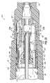
- FIG. 6is a cross-sectional view of the catheter hub of FIGS. 3A-3C for purposes of explaining the interaction of the catheter hub and the needle tip spring protector of the present invention
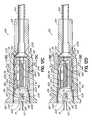
- FIG. 7is a cross-sectional view of the assembled catheter assembly of FIGS. 3A-3C , wherein the needle is in an extended position and the spring is in an armed state;
- FIG. 8is a cross-sectional view of the catheter assembly of FIGS. 3A-3C with the needle moved to a retracted position and the spring in an activated state;
- FIGS. 9A and 9Bare cross-sectional side and cross-sectional end views of the needle tip spring protector of FIG. 4 when the needle extends through the spring in an armed state;
- FIGS. 10A and 10Bare cross-sectional side and cross-sectional end views that depict the changes that occur in the needle tip spring protector of FIGS. 9A and 9B as the spring transitions from the armed state to the activated state;
- FIGS. 11A and 11Bare cross-sectional side and cross-sectional end views that depict the needle tip spring protector of FIGS. 10A and 10B after the spring reaches the activated state;
- FIG. 12Ais a cross-sectional elevational view of a catheter assembly depicting a third embodiment of a needle tip spring protector in accordance with the principles of the present invention, prior to introducing a needle, and with the spring wound and in a first axial position.
- FIG. 12Bis a cross-sectional elevational view of the catheter assembly of FIG. 12A after introducing a needle, and with the spring in a second axial position.
- FIG. 12Cis a cross-sectional elevational view of the catheter assembly of FIG. 12B after retracting the needle.
- FIG. 12Da cross-sectional elevational view of the catheter assembly of FIG. 12C with the spring in the gripping state.
- FIG. 12Ea cross-sectional elevational view of the catheter assembly of FIG. 12D with the spring retracted to its first axial position, and the resilient arms flexing.
- FIG. 12Fa cross-sectional elevational view of the catheter assembly of FIG. 12E with the needle and needle tip spring protector nearly removed.
- FIGS. 13A-13Dare cross-sectional views of the needle tip spring protector of FIGS. 12A-12D taken along lines 13 A- 13 A of FIG. 12A , 13 B- 13 B of FIG. 12B , 13 C- 13 C of FIG. 12C , and 13 D- 13 D of FIG. 12D ;
- FIG. 14is a perspective view of a catheter assembly including a fourth embodiment (not visible) of a needle tip spring protector in accordance with the principles of the present invention
- FIG. 15is an exploded view of the catheter assembly of FIG. 14 , with the needle tip spring protector in the pre-armed state;
- FIG. 16is an exploded view of the needle tip spring protector of FIG. 15 ;
- FIG. 16Ais a partial detail view of the spring and washer of FIG. 15 locked together.
- FIG. 17is an elevational side view cross-section of the needle tip spring protector of FIG. 14 in the assembled state, prior to pre-arming;
- FIG. 17Ais a cross-sectional view as indicated in FIG. 17 ;
- FIG. 17Bis a cross-sectional view as indicated in FIG. 17 ;
- FIG. 18is an elevational side view of the needle tip spring protector of FIG. 14 in the pre-armed state, cross-sectioned at an angle that shows the flexible arm protrusion;
- FIG. 18Ais a cross-sectional view as indicated in FIG. 18 ;
- FIG. 19is an elevational side view cross section of the needle tip spring protector of FIG. 14 in the armed state, with a cannula installed;
- FIG. 19Ais a cross-sectional view as indicated in FIG. 19 ;
- FIG. 20is an elevational side view of part of the catheter assembly of FIG. 14 ;
- FIG. 20Ais a partial cross-sectional view of as indicated in FIG. 20 ;
- FIG. 21is an elevational side view of part of the catheter assembly of FIG. 14 , with the cannula being withdrawn and the spring protector about to fire;
- FIG. 21Ais a cross-sectional view as indicated in FIG. 21 ;
- FIG. 22is an elevational side view cross-section of the needle tip spring protector of FIG. 14 after it has fired, and been withdrawn from the catheter hub;
- FIG. 22Ais a cross-sectional view as indicated in FIG. 22 .
- a needle tip spring protector 10that includes a resilient member 12 to surround a needle 14 in accordance with this invention.
- the resilient member 12is shown as a spring 16 .
- one embodiment of the needle tip spring protector 10may include simply a spring 16 surrounding a needle 14 (such as when used with a hypodermic needle).
- the needle 14may be any of a variety of medical needles. Accordingly, one of ordinary skill will recognize that the needle tip spring protector described herein will operate with conventional needles as well as with cannulae for catheter assemblies and the like.
- a tip 18 of the needle 14is exposed so that the needle 14 may be used for penetration into a body of a patient.
- the labeling conventionwill be that the tip 18 is at the distal end 20 of the needle 14 .
- their respective distal endswill be the end that is furthest from a healthcare worker (and nearest the patient) and the proximal end will be the end closest to the healthcare worker (and furthest from the patient).
- the needle 14includes a shaft 22 with a hollow chamber 24 that operates as a fluid passageway through needle 14 .
- the shaft 22extends from the distal end 20 in a proximal direction to a proximal end (not shown).
- the tip 18 of the needle 14includes a region 26 that varies in diameter from a nominal diameter of shaft 22 to a sharp point 28 .
- a portion of the needle shaft 22is circumferentially surrounded by the spring 16 .
- the spring 16defines a passage 30 through which the needle 14 passes and includes a proximal end 32 and a distal end 34 .
- the proximal and distal ends 32 , 34are movable relative to one another such that if, for example, the proximal end 32 were restrained, the distal end 34 could be wound by rotating it against the rotational bias of the spring 16 .
- the spring 16may be a conventional torsion spring, which has a rest state defined as when the spring is not restrained by any objects, and includes a particular inner diameter 36 .
- Stainless steel, piano wire, and other similar materialsare examples of materials which may be used to construct spring 16 .
- Such a spring 16is typically constructed from uniformly round stock formed into a plurality of turns. However, spring stock having other cross-section profiles, such as rectangular, may be used as well.
- a cross-section of the spring 16may be circular, it will be recognized by those skilled in the art that it need not be of any particular shape, so long as the inner surface 38 includes a plurality of contact points that create a virtual or effective inner diameter.
- These contact pointsare the locations where the inner surface 38 of the spring 16 contacts the needle shaft 22 to grip the shaft 22 when the spring 16 is in a gripping state.
- the diameter 36is larger when spring 16 is in the gripping state than when spring 16 is in the rest state.
- the physical size of the spring 16may depend on the needle 14 .
- the spring 16is selected to permit movement of the needle 14 when the spring 16 is in its wound or armed state but will grippingly engage the needle 14 once the spring 16 moves to its gripping state while trying to unwind toward its rest state.
- the spring 16includes a first aspect and a second aspect, which may be ends of the spring 16 that are capable of being wound relative to one another such that the inner diameter 36 of the spring 16 increases. More specifically, when the first aspect, such as the distal end 34 , of the spring 16 is “wound,” a rotational force is applied to the first aspect against the rotational bias of the spring 16 , while the second aspect, such as the proximal end 32 , remains fixed. This winding expands the inner diameter 36 of the spring 16 by moving the inner surface 38 of the spring 16 radially outward. When wound, the spring 16 is in an armed state and includes stored energy capable of moving the spring 16 toward its rest position. To maintain the armed state, the distal end 34 is restrained from moving, at least temporarily.
- first aspectmay be wound while the second aspect is held in a fixed position; the second aspect may be wound while the first aspect is held in a fixed position; or the first and second aspects may each be wound in directions opposite to one another.
- the inner diameter 36it is not necessary for the inner diameter 36 to be expanded such that the inner surface 38 of the spring 16 does not contact the needle 14 , so long as the needle 14 is not gripped, and can move axially relative to the spring 16 .
- FIGS. 1 and 1Aillustrate the needle 14 in a first, extended position and the spring 16 in the armed state such that its inner diameter 36 permits the needle 14 to slide through the passage 30 of spring 16 .
- the spring 16is able to remain relatively motionless with respect to a patient while the needle 14 is withdrawn from the patient.
- FIGS. 2 and 2Aillustrate the needle 14 in a second, retracted position and the spring 16 in a gripping state.
- the needle 14is moved to the retracted position by moving it in a proximal direction such that the tip 18 thereof is moved towards the spring 16 .
- the needle 14is retracted to a position such that at least a portion of the tip 18 is proximal of the distal end 34 of the spring 16
- the restraint on the distal end 34 of the spring 16is removed such that the distal end 34 is allowed to rotate in the direction of the rotational bias of the spring 16 .
- the spring 16moves toward its rest state (and its gripping state) such that the inner diameter 36 of the spring 16 decreases and approaches the outer diameter of needle 14 and grips thereto in the gripping state of the spring 16 .
- the needle 14when the needle 14 is in the extended position ( FIGS. 1 and 1A ), at least a portion of the needle 14 is disposed within the spring 16 .
- the spring 16 having a spring axis 40is held in substantial coaxial alignment with the needle 14 having a needle axis 42 , due to the presence of the needle 14 within the passage 30 of the spring 16 .
- the distal end 34 of the spring 16will move to a point that allows at least a portion of the spring 16 , such as the distal end 34 , to move relative to the needle 14 . This allows the spring 16 to move away from (see FIG.
- a bearing surface(not shown) to then rotate in the direction of the rotational bias of the spring 16 .
- the spring 16may move out of contact with a bearing surface (not shown) due to a portion of the spring 16 moving out of substantial coaxial alignment with the needle 14 , or due to an alteration of space between a portion of the needle 14 , such as region 26 , and the spring 16 .
- the spring 16may then rotate or unwind.
- the inner diameter 36 of the spring 16is reduced to the gripping state so that spring 16 grippingly engages shaft 22 .
- the needle 14 and the spring 16are engaged such that the needle 14 cannot move relative to the spring 16 . Because the spring 16 securely engages the outside of the shaft 22 , the needle tip 18 remains protected even though the needle 14 may continue to be moved relative to a patient or when it is subjected to forces that could reasonably occur during subsequent handling of the needle 14 .
- the spring 16may substantially surround the tip 18 and protect healthcare workers from accidental contact with the tip 18 .
- FIG. 2shows the entire tip 18 enclosed within the spring 16
- other embodiments described latercontemplate only a portion of the tip 18 enclosed within the spring 16 (with the remainder otherwise protected, such as within a housing).
- the tip 18 of the needle 14when described as being enclosed within the spring 16 , such description may include the tip 18 entirely within the spring 16 or only a portion of the tip 18 within the spring 16 .
- the spring 16provides a simple-to-manufacture, reliable, easily actuated, and inexpensive means to protect a healthcare worker from inadvertent contact with the needle tip 18 .
- a catheter assembly 100including a second embodiment of a needle tip spring protector 102 .
- the needle tip spring protector 102may include essentially the same spring 16 as the needle tip spring protector 10 of FIGS. 1-2A , but needle tip spring protector 102 also includes a housing 104 having a passage 106 ( FIG. 4 ) for receiving needle 14 therethrough, and first and second resilient arms 108 , 110 . At least one of the resilient arms 108 , 110 defines a passage 112 ( FIG. 4 ) generally axially aligned with passage 106 for receiving needle 14 therethrough. First and second resilient arms 108 , 110 interact with a catheter hub 114 to control release of needle tip spring protector 102 from catheter hub 114 .
- FIG. 3Adepicts the catheter assembly 100 as an assembled unit that is in a position to be inserted within a patient.
- the catheter assembly 100includes a needle hub 116 with needle 14 extending distally therefrom.
- Catheter hub 114 of catheter assembly 100includes a luer fitting 118 on a proximal end 120 and a catheter tube 122 extending distally from a distal end 124 .
- Needle shaft 22extends through housing 104 , spring 16 , catheter hub 114 , and catheter tube 122 , with an exposed tip 18 exiting a distal end 125 of the catheter tube 122 in a first, extended position of needle 14 .
- the needle tip spring protector 102is configured to permit motion of the needle 14 relative to the needle tip spring protector 102 .
- the shaft 22 of the needle 14is permitted to move freely through the needle tip spring protector 102 in a generally proximal direction such that the needle 14 moves while the needle tip spring protector 102 remains relatively motionless relative to a patient.
- needle hub 116is pulled proximally relative to needle tip spring protector 102 to begin to withdraw needle 14 and to begin to separate needle hub 116 from housing 104 of needle tip spring protector 102 , as seen in FIG. 3B .
- the spring 16 of the needle tip spring protector 102will move to grippingly engage the needle 14 similar to the manner described with respect to FIG. 2 .
- the needle 14has limited movement relative to the needle tip spring protector 102 . Accordingly, continued retraction of the needle 14 will result in the configuration of FIG. 3C in which the needle tip spring protector 102 is attached around the tip 18 of the needle 14 and disengages from the inside of the catheter hub 114 .
- healthcare workersare protected from inadvertent contact with the tip 18 of the needle 14 and the catheter tube 122 remains inserted within the patient.
- the needle tip spring protector 102includes housing 104 having passage 106 through which the needle 14 can pass.
- the material of the housing 104may be plastic, stainless steel, non-reactive metal and other similar materials.
- a distal end 126 of the housing 104includes first resilient arm 108 and second resilient arm 110 .
- the second resilient arm 110includes passage 112 generally axially aligned with passage 106 .
- At least one arm, and as in the illustrated embodiment, both of arms 108 , 110may include a detent 128 at distal ends 130 , 132 of first and second resilient arms 108 , 110 , respectively, to define segments of an annular ring 134 .
- the first and second resilient arms 108 , 110interact with features of the catheter hub 114 , as explained below, to control the release of the needle tip spring protector 102 from the catheter hub 114 .
- the first and second resilient arms 108 , 110are exemplary in nature, however, and the present invention contemplates embodiments in which the housing 104 includes one resilient arm, or includes more than two resilient arms.
- Spring 16is disposed at least partially in passage 106 and extends therefrom in the illustrated embodiment.
- the second resilient arm 110includes a bearing surface 136 on which the distal end 34 of the spring 16 engages.
- the bearing surface 136is generally flat and parallel with the distal end 34 of the spring 16 .
- a channel 138 or similar meansis shown that constrains the proximal end 32 of the spring 16 .
- the proximal end 32will bear against a rigid side of the channel 138 , preventing the proximal end 32 from moving (e.g., rotating) relative to the housing 104 .
- the spring 16will be in an armed state having passage 30 including inner diameter 36 through which needle 14 can pass.
- the passage 30is sized large enough to accept the needle 14 but sized small enough that needle 14 , when present, prevents the second resilient arm 110 from flexing or moving.
- the catheter hub 114includes an inner chamber 140 defined by an interior surface 142 having a proximal portion 144 tapered in accordance with ISO or other applicable standards for female luers.
- the inner chamber 140defines a housing-engaging element 146 for cooperating with needle tip spring protector 102 .
- the housing-engaging element 146is a generally annular protrusion 148 extending radially inward from interior surface 142 into inner chamber 140 .
- Annular protrusion 148is generally distal of luer tapered proximal portion 144 so as not to interfere with male luer taper connections to catheter hub 114 .
- the protrusion 148may, for example, be formed from an annular lip that extends along the entire inside circumference of the inner chamber 140 .
- the housing-engaging element 146may include a plurality of protrusions, a groove, a plurality of grooves, or an annular groove that extends about the inside circumference of the inner chamber 140 .
- Annular protrusion 148 and detents 128cooperate to hold needle tip spring protector 102 to catheter hub 114 in the extended position of needle 14 and allow for release thereof when needle 14 moves proximally towards the retracted position.
- the shaft 22 thereofin passage 112 , thus limiting the ability of second resilient arm 110 to compress (i.e., to flex radially inwardly).
- detents 128define an outer diameter of annular ring 134 that is slightly greater than the inner diameter of annular protrusion 148 , and which may closely correspond to the inner diameter of catheter hub interior surface 142 just distal of annular protrusion 148 .
- detents 128provide a generally rigid hold to catheter hub 114 by cooperating with the distal-facing surface of annular protrusion 148 .
- the proximal end 32 of the spring 16is held in place (e.g., channel 138 ) while the spring 16 is in an armed state with its distal end 34 restrained against the bearing surface 136 .
- the needle 14is allowed to freely move through the housing 104 , the spring 16 , the catheter hub 114 , and the catheter tube 122 .
- detents 128are seated distal of annular protrusion 148 in catheter hub 114 with a light frictional fit that allows the healthcare worker (not shown) to rotate catheter hub 114 relative to needle tip spring protector 102 .
- the needle tip spring protector 102is fixedly engaged with the catheter hub 114 in FIG.
- first and second resilient arms 108 , 110are allowed to flex and move past the protrusion 148 and allow the needle tip spring protector 102 to release from the catheter hub 114 .
- needle shaft 22is effectively proximally beyond passage 112 , such as with tip 18 protected by needle tip spring protector 102 in the retracted position of needle 14 , as seen in FIG. 8 , that either or both of first and second resilient arms 108 , 110 are flexed.
- needle hub 116continues proximal pulling on needle hub 116 causes one or both of resilient arms 108 , 110 to flex enough that detents 128 move proximally of annular protrusion 148 , and then to flex or expand back to the nominal position.
- the spring 16may move out of contact with bearing surface 136 by alternate mechanisms. For example, with reference to FIGS. 7-11B , when the needle 14 is in the extended position, the needle 14 and spring 16 are in substantial coaxial alignment. The spring 16 is prevented from moving out of substantial coaxial alignment due to the presence of the needle 14 within the passage 30 of the spring 16 . As the needle 14 is retracted, the distal end 20 of the needle 14 will move to a point that allows at least a segment of the spring 16 , such as the distal end 34 , to move relative to the needle 14 . For example, as in FIG.
- the needle 14has been retracted such that its distal tip 18 is within the passage 112 of the second resilient arm 110 .
- the spring 16is in an armed state with its distal end 34 constrained against a bearing surface 136 of the second resilient arm 110 of the housing 104 .
- the distal end 34 of the spring 16terminates in a relatively flat surface 154 that sits on a relatively flat bearing surface 136 .
- the rotational bias of the spring 16urges the distal end 34 in a counter-clockwise direction in this example.
- the distal end 34could also be positioned to account for a clockwise rotating spring 16 .
- the spring 16In order for the distal end 34 to rotate, though, the spring 16 would have to flex upwardly so that the distal end 34 can slip past the bearing surface 136 . Such upward flexing is prevented, however, by the presence of the needle 14 . As the spring 16 attempts to flex upwardly, it is stopped when the inner surface 38 contacts the shaft 22 of needle 14 . In such a configuration, the needle 14 and spring 16 are in substantial coaxial alignment. In FIG. 10A , the needle 14 is withdrawn to a point where a portion of the needle tip 18 , for example region 26 , is proximal of the distal end 34 of the spring 16 .
- the distal end 34is able to flex such that it can escape the restraint provided by the bearing surface 136 and can begin rotation in the counter-clockwise direction, as shown in FIG. 10B .
- the passing of a portion of the tip 18 of the needle 14 past the distal end 34 of the spring 16allows at least a portion of the spring 16 to move out of substantial coaxial alignment with the needle 14 to activate the release of the spring 16 to the gripping state.
- a portion of the spring 16need not move out of substantial coaxial alignment with needle 14 to release spring 16 from bearing surface 136 .
- region 26 of needle 14can provide space for spring 16 to release from bearing surface 136 without the spring 16 moving out of substantial coaxial alignment with needle 14 . It will also be recognized, that although FIG. 10B is drawn with region 26 downwards towards bearing 136 , thus allowing spring 16 to begin to deflect upwardly as soon as region 26 enters spring 16 , activation would still occur even if region 26 were oriented upwards, or at any other orientation, although activation may be delayed until sharp point 28 is fully within spring 16 .
- FIGS. 11A and 11Billustrate the spring 16 after it has been activated and grippingly engages the shaft 22 of the needle 14 .
- the spring 16is restrained within the needle tip spring protector 102 via its proximal end 32 .
- movement of the needle 14will be directly transferred to the needle tip spring protector 102 through the engagement of the spring 16 with the needle 14 .
- the second resilient arm 110is free to flex inwardly.
- the first resilient arm 108is also free to flex inwardly and thus, the resilient arms 108 , 110 can flex past the annular protrusion 148 to allow the needle tip spring protector 102 to release from the catheter hub 114 .
- the normal activity of retracting the needle hub 116 from the catheter hub 114activates the needle tip spring protector 102 without any additional action by the healthcare worker, and further retraction of the needle hub 116 , after activation, releases the needle tip spring protector 102 from the catheter hub 114 without additional manipulation by the healthcare worker.
- catheter assembly 200which may be essentially the same as catheter assembly 100 described above, but including a third embodiment of a needle tip spring protector 202 .
- Needle tip spring protector 202may include essentially the same spring 16 as in the first and second embodiments.
- Needle tip spring protector 202includes a housing 204 having a passage 206 for receiving needle 14 therethrough, and first and second resilient arms 208 , 210 wherein at least one arm defines a passage 212 generally axially aligned with passage 206 .
- FIG. 12Adepicts the catheter assembly 200 prior to introduction of needle 14 to the assembly.
- FIG. 12Bdepicts the catheter assembly 200 as an assembled unit with needle 14 introduced to the assembly.
- FIGS. 12C-12Fdepict the operation of the needle tip spring protector 202 , and the relative positions of catheter hub 114 and needle tip spring protector 202 during use.
- the catheter assembly 200includes a needle hub 116 ( FIG. 3B ) with needle 14 extending therefrom.
- Catheter hub 114 of catheter assembly 200includes luer fitting 118 on its proximal end and catheter tube 122 extending distally from the distal end 124 of the catheter hub 114 .
- Needle shaft 22extends through housing 204 , spring 16 , catheter hub 114 , and catheter tube 122 with an exposed tip 18 exiting the distal end 125 of the catheter tube 122 in an extended position of the needle 14 (as shown in FIG. 12B ).
- the spring 16has a first axial position and a second axial position relative to housing 204 .
- the spring 16is shown in the first axial position prior to insertion of the needle 14 into the catheter assembly 200 .
- FIG. 12Bdepicts the spring 16 after having been moved to the second axial position, with the needle 14 inserted through the needle tip spring protector 202 .
- the spring 16may be moved from the first axial position to the second axial position by using a separate tool (not shown) to push the spring 16 in a distal direction.
- the spring 16is in an armed state in the first axial position, and remains in an armed state when moved to the second axial position.
- An armed state in the first axial positionis obtained by winding the spring 16 by holding the distal end 34 of the spring 16 against its rotational bias and in contact with a ledge 213 defined by an inner surface 214 of housing 204 , and holding the proximal end 32 against its rotational bias and in contact with a tool (not shown) outside of the housing 204 .
- the spring 16is moved slightly distally so that proximal end 32 is placed on a contour 216 of a notch 218 in a proximal end 220 of the housing 204 as seen in FIG. 12A .
- the distal end 34 of the spring 16remains in contact with the ledge 213 until it is moved onto a bearing surface 222 (refer to FIGS. 12A and 13A ), and therefore does not rotate in the direction of the rotational bias of the spring 16 .
- the distal end 34 of the spring 16moves out of contact with the ledge 213 of the housing 204 to be received against the bearing surface 222 of the housing 204 .
- the proximal end 32 of the spring 16moves distally along the contour 216 of the notch 218 .
- the notch 218 of the illustrated embodimentis in a general U or V shape with an open end 224 and a closed end 226 .
- a U or V shapeis not necessary, and any shape may be used that serves the principles of the present invention.
- the proximal end 32Prior to being received at the distal portion 228 , the proximal end 32 passes through a narrowed portion 230 formed by a protrusion 232 .
- the narrowed portion 230is shaped such that it will allow passage of the proximal end 32 in a direction from the open end 224 to the distal portion 228 , but will prevent passage of the proximal end 32 in a direction from the distal portion 228 to the open end 224 . Since the proximal end 32 of the spring 16 is received on a distal side of protrusion 232 , the rotational bias of the spring 16 will keep the proximal end 32 in the distal portion 228 while spring 16 is in the armed state.
- the distal end 238 of the housing 204includes first resilient arm 208 and second resilient arm 210 .
- the second resilient arm 210includes a passage 212 generally axially aligned with passage 206 .
- At least one arm, and as in the illustrated embodiment, both of arms 208 , 210include a detent 240 at distal ends 242 , 244 , respectively, to define segments of an annular ring 246 .
- These first and second resilient arms 208 , 210interact with features of the catheter hub 114 , as explained below, to control the release of the needle tip spring protector 202 from the catheter hub 114 .
- first resilient arm 208has a surface 248 , which may be provided by a leg 250 , that contacts and confronts the outer surface 251 of the spring 16 when the spring 16 is in the second axial position.
- leg 250is located at a distal end 242 of the first resilient arm 208 .
- any surface of first resilient arm 208may be used to contact spring 16 , and thus does not necessarily require a downwardly-depending protrusion, such as leg 250 .
- first resilient arm 208is disposed proximally of the distal end 238 of the housing 204 .
- detents 240are seated distal of annular protrusion 148 in catheter hub 114 with a light frictional fit that allows the healthcare worker (not shown) to rotate catheter hub 114 relative to needle tip spring protector 202 .
- the needle tip spring protector 202is fixedly engaged with the catheter hub 114 (as in FIG. 12B ) such that any forces resulting from proximal movement of the needle 14 (e.g., via proximal movement of needle hub 116 by a healthcare worker) are insufficient to release the needle tip spring protector 202 from the catheter hub 114 .
- the needle tip spring protector 202activates, such that spring 16 grippingly engages the shaft 22 of the needle 14 ( FIG. 12D ), the needle tip spring protector 202 and needle 14 are effectively secured together such that the proximal movement of needle 14 generates a force sufficient to overcome the holding force of housing 204 to catheter hub 114 . More particularly, with needle 14 out of the way, the first and second resilient arms 208 , 210 are allowed to flex and move past the protrusion 148 and allow the needle tip spring protector 202 to release from the catheter hub 114 .
- first and second resilient arms 208 , 210are flexed.
- continued proximal pulling on needle hub 116causes one or both of resilient arms 208 , 210 to flex enough that detents 240 move proximally of annular protrusion 148 while the surface 248 of leg 250 moves into the space formerly occupied by the spring 16 ( FIG. 12E ), and then to flex or expand back to the nominal position ( FIG. 12F ).
- the outer surface 251 of the spring 16is moved proximally and out of contact with the leg 250 .
- Thisprovides space for the first resilient arm 208 to flex to release the housing 204 from the interior of the catheter hub 114 .
- the positioning of the spring 16 in contact with the leg 250 in the second axial positionprevents the housing 204 from releasing from the catheter hub 114 until the spring 16 has moved to the gripping state to grip the needle 14 . This ensures that the housing 204 cannot be removed from the catheter hub 114 until the needle tip 18 is protected.
- the second resilient arm 210With the needle 14 removed from the passage 212 , the second resilient arm 210 is free to flex, and thus can move away from protrusion 148 to allow the needle tip spring protector 202 to release from the catheter hub 114 , as described above. It will be recognized by those skilled in the art that the second resilient arm 210 need not be received distally of a protrusion 148 , but may engage other housing-engaging elements 146 , such as a plurality of protrusions, a groove, a plurality of grooves, or an annular groove.
- catheter assembly 200is inserted into a patient and, while the catheter hub 114 is held steady, the needle hub 116 and needle 14 can be retracted to withdraw the needle 14 from the patient (as shown in FIGS. 12C-12F ).
- the needle tip 18will pass through the passage 212 towards the spring 16 .
- the distal end 18 of the needle 14will move to a point that allows at least a segment of the spring 16 , such as the distal end 34 , to move relative to the needle 14 .
- the region 26 of the needle 14will move to a position adjacent distal end 34 of spring 16 .
- Region 26provides space for the distal end 34 of spring 16 to move away from bearing surface 222 and to then rotate in the direction of the rotational bias of spring 16 .
- the inner diameter 36 of the spring 16is reduced to the gripping state so that it grippingly engages the shaft 22 , as shown in FIGS. 12D and 13D .
- FIGS. 12E and 12Fthe needle tip spring protector 202 disengages from the inside of the catheter hub 114 while surrounding tip 18 of needle 14 .
- proximal end 32 of spring 16will cooperatively move from distal portion 228 of notch 218 (second axial position) to closed end 226 of notch 218 (third axial position).
- Contact of the proximal end 32 of spring 16 with closed end 226provides the force, upon continued retraction of needle 14 , to withdraw needle tip spring protector 202 from catheter hub 114 .
- the needle tip spring protector 202engages the inside of the catheter hub 114 with a holding force greater than the force that the needle 14 may exert on the needle tip spring protector 202 while the needle 14 is being retracted.
- the needle tip spring protector 202remains attached to the catheter hub 114 while the needle hub 116 and needle 14 are being retracted to withdraw the needle 14 from the patient.
- the needle tip spring protector 202activates so as to grip the shaft 22 of the needle 14 , the gripping force is greater than the holding force between the catheter hub 114 and the needle tip spring protector 202 .
- the needle tip spring protector 202is released from the catheter hub 114 and remains in position covering the tip 18 of the needle 14 .
- this embodiment of the present inventionprovides a passive release of the needle tip spring protector 202 from the catheter hub 114 .
- the normal activity of retracting the needle hub 116 from the catheter hub 114activates the needle tip spring protector 202 without any additional action by the healthcare worker.
- further retraction of the needle hubreleases the needle tip spring protector 202 from the catheter hub 114 without additional manipulation by the healthcare worker.
- the present inventionprovides a needle tip spring protector 202 for a catheter assembly 200 that includes both passive activation and passive release.
- FIGS. 14-22Adepict a catheter assembly 300 consisting of a needle hub 116 having a needle 14 extending distally thereof, a needle tip spring protector 302 , and a catheter hub 114 having catheter tube 122 extending distally thereof.
- the needle 14When assembled, the needle 14 extends through the needle tip spring protector 302 and passes through the catheter tube 122 so that the tip 18 is protruding beyond the distal end 125 of the catheter tube 122 .
- the needle tip spring protector 302is disposed in the catheter hub 114 and is adapted to protect the tip 18 of needle 14 when the needle 16 is withdrawn.
- the details of the needle tip spring protector 302are illustrated in FIGS. 16-17A and include a cup 304 , a washer 306 , a spring 16 , and a housing 308 that collectively cooperate to perform a tip protection function of needle 14 .
- the cup 304has a base 310 with a proximal face 312 , a distal face 314 and an aperture 316 through base 310 and extending between proximal and distal faces 312 , 314 .
- the aperture 316is sized to receive the shaft 22 of needle 14 therethrough.
- Four arms 318extend distally from the base 310 and define an inner chamber 320 .
- a center axis 322 of the cup 304is defined as being through the center of aperture 316 , generally perpendicular to the base 310 , and approximately in-line with the center of the four arms 318 .
- the angle between the base 310 and the arms 318is greater than 90 degrees, and preferably approximately 95 degrees, resulting in a slight flaring of the arms 318 in a radially outward direction.
- Each arm 318has an interior tab 324 , an exterior tab 326 on opposite sides of the arm 318 , and a distal tab 328 opposite the base 310 .
- the interior tabs 324 and exterior tabs 326have an overlapping relationship and define at least in part inner chamber 320 .
- the inner tab 324 of one arm 318is nearer to, but does not contact, the exterior tab 326 of the neighboring arm 318 .
- This arrangementallows the four arms 318 to be squeezed or flexed inwardly, changing the angle relative to the base 310 from approximately 95 degrees, to a smaller angle such as approximately 90 degrees, before the interior and exterior tabs 324 , 326 come into contact with one another.
- the exterior tab 326has a proximal tab portion 330 that is angled radially outwardly from the center axis 322 of the cup 304 , terminating at a locking edge 332 .
- Each of the distal tabs 328has a circumferentially extending nose that defines a locking point 334 at the end thereof.
- Each of the distal tabs 326has an insertion portion 336 that is angled toward the center axis 322 to aid in the entry of the four arms 318 into the proximal end of the housing 308 during assembly.
- One of the four interior tabs 324( FIG. 17A ) is an arming tab 338 which is longer than the other three interior tabs 324 and has a generally V-shaped notch 340 formed therein.
- a semicircular cutout 342 in the edge of the base 310provides an optional visual and tactile reference for the location of the arming tab 338 .
- Opposing windows 344are defined between neighboring arms 318 and adjacent base 310 make it possible to pass objects through the inner chamber 320 . As described below, the windows 344 may be used during assembly of the needle tip spring protector 302 .
- the base 310may further include one or more cutouts 346 used in the manufacturing and/or assembly of the tip protector 302 .
- the washer 306has a head 348 , a stem 350 extending distally thereof, and a passage 351 extending through washer 306 .
- the head 348includes a proximal face 352 , a first chamfer 354 , a second chamfer 356 , and a generally cylindrical portion 358 .
- the stem 350is generally cylindrical, terminates at a distal face 359 , and has a cross-dimension less than a cross-dimension of the cylindrical portion 358 of head 348 to define a distally facing shoulder 360 .
- the washer 306includes a slot 362 extending generally in a proximal-distal direction and open along the outer periphery of the washer 306 .
- the portion of slot 362 in stem 350includes a first lead 364 that defines a first corner 366 and a second lead 368 that defines a second corner 370 .
- the washer slot 362is in communication with a spring pocket 372 that defines a first stop surface 374 , a second stop surface 376 , a proximal stop surface 378 and a distal stop surface 380 .
- the spring pocket 372is adapted to receive the proximal end 32 of spring 16 therein.
- Passage 351may include proximal and distal chamfers 382 , 384 adjacent proximal and distal faces 352 , 359 , respectively.
- the passage 351has a stepped configuration to define a distally facing shoulder 386 therein.
- the second chamfer 356 of head 348includes an entry portion 388 and the cylindrical portion 358 of head 348 includes an entry flat 390 .
- the housing 308includes a proximal face 400 , a proximal portion 402 , an intermediate portion 404 , a distal portion 406 , and a distal face 408 .
- the portions of housing 308have a stepped configuration to define a first distally facing shoulder 410 between proximal portion 402 and intermediate portion 404 and a second distally facing shoulder 412 between intermediate portion 404 and distal portion 406 .
- Housing 308may also include one or more ramp gussets 414 between proximal portion 402 and intermediate portion 404 .
- Housing 308may further include one or more chamfers such as chamfers 416 , 418 between the various portions or between a portion and a respective face.
- Housing 308further includes first and second interconnected gaps 420 , 422 to define a resilient arm 424 .
- the resilient arm 424is substantially flat on the side facing away from a center axis 426 of the housing 308 .
- the flat surface 428continues proximally across the proximal portion 402 to the proximal face 400 where it defines a large flat 430 .
- the resilient arm 424has a detent 128 that creates a segment of an annular ring 432 and further comprises a lead 434 and a flat 436 ( FIG. 18 ).
- Interior features of the housing 308include a proximal cavity 438 having a first diameter and a distal cavity 442 having a second reduced diameter to define a shoulder 446 between the two cavities.
- the proximal cavity 438has an annular groove 448 formed therein and adjacent proximal face 400 .
- the distal cavity 442is bounded at the distal end thereof by an inner face 450 of distal portion 406 .
- distal portion 406includes a passage 451 therethrough in communication with distal cavity 442 and is sized to receive the shaft 22 of needle 14 therethrough.
- the interior of housing 308further includes a plurality (e.g., four) circumferentially spaced ribs 452 ( FIG. 17B ).
- the ribs 452have proximally extending rib leads 454 and curved inner surfaces 456 that form an effective discontinuous rib diameter 458 .
- the rib 452 that is adjacent to the resilient arm 424 and to the distal end 34 of spring 16has a rib relief 460 .
- the resilient arm 424has a bearing surface 462 that defines a pre-arm portion 464 ( FIG. 17B ) and an arming portion 466 that is distal of the pre-arm portion 464 .
- housing 308The interconnectability of the various components of housing 308 will now be described. This includes, for example, placing the needle tip spring protector 302 in a pre-arm state and an armed state. Additionally, assembling a catheter assembly 300 including the needle tip spring protector 302 will also be described.
- the cup 304is placed base down over a first tooling pin (not shown) that passes through the aperture 316 in the base 310 .
- Two other tooling pins(not shown) are passed through opposing windows 344 in the cup 304 to lie substantially horizontal on either side of and generally perpendicular to the first tooling pin.
- the washer 306proximal face down ( FIG.
- the washer 306is then lowered onto the first tooling pin and into the cup 304 to rest on the two horizontal pins that extend through windows 344 .
- the horizontal pinslocate the spring pocket 372 of the washer 306 in vertical alignment with the notch 340 in the arming tab 338 .
- the spring 16is placed over the first tooling pin, and lowered such that the proximal end 32 engages the spring slot 362 and into the spring pocket 372 of the washer 306 ( FIG. 16A ).
- the housing 308is circumferentially oriented so that the distal end 34 of the spring 16 will pass between the rib relief 460 and the resilient arm 424 .
- the housing 308is then lowered over the first tooling pin so that the ribs 452 pass over the outer surface 251 of spring 16 .
- the insertion portions 336 of the arms 318enter the proximal cavity 438 of the housing 308 , and the arms 318 begin to flex from their radially outward position (e.g., angled approximately 95 degrees relative to base 310 ) toward their radially inward position (e.g., angled approximately 90 degrees relative to the base 310 ).
- the housing 308 and cup 304are pushed together until the locking point 334 on the distal tabs 328 enter the annular groove 448 .
- the distal end 34 of the spring 16reaches the pre-arm portion 464 of the bearing surface 462 on resilient arm 424 .
- the arms 318 of the cup 304are flexed to their radially inward position by the housing 308 and the resiliency of the arms 318 exert a radially outward force through the locking points 334 on the inside of the housing 308 at the annular groove 448 to retain the cup 304 thereto.
- the housing 308is rotated in the direction of the arrow ( FIG. 17B ) relative to the cup 304 , which is kept stationary by the two horizontal pins through the opposing windows 344 or by other suitable means. This rotation immediately brings the pre-arm portion 464 into contact with the distal end 34 of the spring 16 , which then drives the proximal end 32 of spring 16 securely into the notch 340 on the arming tab 338 of the cup 304 .
- Continued rotation of the housing 308such as for example, for approximately two and one-half turns total, enlarges the spring diameter 36 as shown in FIGS. 18 and 18A .
- the needle tip spring protector 302is stable.
- the housing 308 and the cup 304are prevented from rotating relative to each other in the reverse direction by the locking points 334 engaging the annular groove 448 .
- the circumferentially extending nose on the distal tabs 328is configured to allow rotation of the housing 308 in a first circumferential direction but prevent rotation in the opposite circumferential direction.
- the washer 306is prevented from moving toward the cup base 310 by the proximal end 32 of the spring 16 that firmly holds the washer 306 at the height of the notch 340 .
- the distal end 34 of spring 16will not unwind because the now enlarged outside diameter of the spring 16 has no room for movement within the effective rib diameter 458 of ribs 452 . Accordingly, the distal end 34 is prevented from flexing away from or otherwise disengaging the pre-arm portion 464 of the bearing surface 462 .
- the two horizontal pinsmay be removed and the needle tip spring protector 302 ( FIGS. 15 and 18 ) can be removed from all tooling and handled and stored for later assembly into a catheter assembly 300 , as will now be described.
- pre-arming the needle tip spring protector 302 by rotation of housing 308 relative to cup 304may also be accomplished in other ways that are contemplated to be within the scope of the invention.
- a flatcould be provided on the needle to be used to interface with a feature in the housing, and the needle could then be rotated to rotate the housing and wind the spring.
- the springmay need to be pre-wound enough to allow the needle to pass, and then be additionally wound to give the spring more torsion to push against the resilient arm.
- the tip 18 of the needle 14is first passed through the needle tip spring protector 302 .
- the distal face 468 of the needle hub 116contacts the proximal face 312 of base 310 and pushes the cup 304 , washer 306 , and spring 16 distally into the proximal cavity 438 and the distal cavity 442 of the housing 308 until the locking edges 332 of the arms 318 engage the annular groove 448 .
- This movementcauses the distal end 34 of spring 16 to move from the pre-arm portion 464 of the bearing surface 462 ( FIGS. 18 and 18A ) to the arming portion 466 ( FIGS. 19 and 19A ).
- this movementalso causes a distal end 34 of the spring 16 to move distally of the ribs 452 .
- the shaft 22 of needle 16prevents deflection of the distal end 34 away from the arming portion 466 of bearing surface 462 .
- the spring 16is capable of unwinding and gripping to needle 14 in the manner described in the previous embodiments when actuated. While armed, the spring 16 applies an outward force to the resilient arm 424 the purpose of which will be described in more detail below.
- the arming method described aboveinvolves pushing the cup 304 into the housing 308 by using the needle hub 116
- other suitable methodsthat move the cup 304 into the housing 308 , or the housing 308 over the cup 304 , while first placing the shaft 22 of needle 14 through the spring 16 , would also serve to arm the needle tip spring protector 302 .
- the needle hub 116 and the needle tip spring protector 302which is coaxially disposed over needle 14 , are inserted into the catheter hub 114 , with the lead 434 of resilient arm 424 easing the distal passing of the detent 128 over the annular protrusion 148 .
- the annular ring 432interacts with the annular protrusion 148 , to prevent the needle tip spring protector 302 from undesirably being removed from the catheter hub 114 .
- the ramp gussets 414 and the proximal portion 402 of housing 308( FIG.
- the needle hub 116may be held in position relative to the catheter hub 114 through a snap-fit feature or in other ways that are old in the art (not shown).
- a healthcare workerneed only use the catheter assembly 300 in the usual manner.
- the region 26 of the needle 14enters the spring 16 , allowing the distal end 34 of spring 16 to deflect away from the arming portion 466 of the bearing surface 462 of the resilient arm 424 .
- the arming portion 466may be angled to facilitate disengagement of the distal end 34 from the arming portion 466 .
- the spring 16unwinds in the direction of its rest state causing the inner diameter 36 of spring 16 to decrease or contract. As in other embodiments, the spring 16 moves towards its gripping state ( FIG.
- the healthcare workercontinues to move the needle hub 116 proximally by pulling in the normal manner.
- the needle 14pulls the spring 16 and washer 306 proximally therewith, causing the washer 306 and spring 16 to come away from the notch 340 and move proximally into the inner chamber 320 such that the proximal face 352 of the washer 306 engages the distal face 314 of the base 310 of cup 304 .
- Further proximal movement of the needle 14applies a force to the cup 304 , which is coupled to the housing 308 by the locking edges 332 engaging the annular groove 448 .
- the resilient arm 424 of housing 308no longer having a force applied to it by the distal end 34 of spring 16 , deflects radially inward to allow the detent 128 to move past the annular protrusion 148 and permit the housing 308 to be removed from the catheter hub 114 . Accordingly, the needle tip spring protector 302 encloses the tip 18 of the needle 14 and protects the healthcare worker from inadvertent contact therewith.
- a feature of this fourth embodimentis that it prevents or reduces the likelihood of accidental or intentional removal of the activated needle tip spring protector 302 by twisting of the needle 14 relative to the needle tip spring protector 302 .
- the needle tip spring protector 302is designed to allow such relative rotation therebetween.
- the washer 306 and inner chamber 320are sized such that when the washer 306 has been pulled into the inner chamber 320 (e.g., during removal of the needle 14 ) the washer 306 is free to spin or rotate within the inner chamber 320 . Accordingly, spring 16 remains in its gripping state regardless of the rotation of the needle 14 relative to the housing 308 of needle tip spring protector 302 . In this way, the spring 16 cannot be rewound or moved back to its armed state.
- the bearing surface that restrains the distal end of the springdoes not necessarily have to be flat or of any particular shape.
- the bearing surfaces and the distal endcan be any of a variety of complimentary shapes that act to temporarily restrain the distal end while the needle is in place but which allow for the passive release of the spring when the tip moves past the distal end.
- the activationcould take place prior to the tip reaching the spring, such as by using a proximal passage in the housing, and a distal passage in the housing to make the needle stable, and then making the needle and spring unstable when the needle exits the distal passage but has not yet reached the spring. This would still result in the needle tip being protected by the housing.
- a needle tip spring protector in accordance with the principles of the present inventiondoes not necessarily have to be part of a catheter assembly.
- the needle tip spring protectormay be part of a hypodermic needle or other, similar device.
- the needle tip spring protectornot the catheter hub, would be moved relative to the needle such that the tip of the needle would enter the needle tip spring protector and passively activate the spring.
- Such a needle tip spring protectorcould also omit features described herein that provide for passive release from a catheter hub, as no such hub is present.
- needles of standard metal finishesand without any geometry such as notches or ridges added
- needles of modified surface finishes or geometrycould also be used, especially if a need to increase the gripping force of the spring on the shaft is required.
Landscapes
- Health & Medical Sciences (AREA)
- Life Sciences & Earth Sciences (AREA)
- Engineering & Computer Science (AREA)
- Hematology (AREA)
- General Health & Medical Sciences (AREA)
- Anesthesiology (AREA)
- Biomedical Technology (AREA)
- Heart & Thoracic Surgery (AREA)
- Veterinary Medicine (AREA)
- Animal Behavior & Ethology (AREA)
- Public Health (AREA)
- Pulmonology (AREA)
- Biophysics (AREA)
- Environmental & Geological Engineering (AREA)
- Vascular Medicine (AREA)
- Media Introduction/Drainage Providing Device (AREA)
- Infusion, Injection, And Reservoir Apparatuses (AREA)
Abstract
Description
Claims (50)
Priority Applications (18)
| Application Number | Priority Date | Filing Date | Title |
|---|---|---|---|
| US12/175,068US7785296B2 (en) | 2008-07-17 | 2008-07-17 | Needle tip spring protector |
| KR1020157035416AKR20160005369A (en) | 2008-07-17 | 2009-06-22 | Needle tip spring protector |
| KR1020157035417AKR20160005370A (en) | 2008-07-17 | 2009-06-22 | Needle tip spring protector |
| JP2011518766AJP5377635B2 (en) | 2008-07-17 | 2009-06-22 | Needle tip spring type protection device |
| KR1020117001246AKR101579169B1 (en) | 2008-07-17 | 2009-06-22 | Needle tip spring protector |
| PCT/US2009/048091WO2010008784A2 (en) | 2008-07-17 | 2009-06-22 | Needle tip spring protector |
| CN200980128072.1ACN102099067B (en) | 2008-07-17 | 2009-06-22 | Needle tip spring protector |
| EP12178057.1AEP2567722B1 (en) | 2008-07-17 | 2009-06-22 | Needle tip spring protector |
| EP09798452.0AEP2313130B1 (en) | 2008-07-17 | 2009-06-22 | Needle tip spring protector |
| AU2009271370AAU2009271370B2 (en) | 2008-07-17 | 2009-06-22 | Needle tip spring protector |
| CA2723093ACA2723093C (en) | 2008-07-17 | 2009-06-22 | Needle tip spring protector |
| ES12178057.1TES2549059T3 (en) | 2008-07-17 | 2009-06-22 | Needle tip spring guard |
| ES12178063.9TES2536536T3 (en) | 2008-07-17 | 2009-06-22 | Needle tip spring guard |
| EP12178063.9AEP2567721B1 (en) | 2008-07-17 | 2009-06-22 | Needle tip spring protector |
| BRPI0912259ABRPI0912259A2 (en) | 2008-07-17 | 2009-06-22 | safety needle and catheter protection devices and method of use of needle protection device |
| MX2010012271AMX2010012271A (en) | 2008-07-17 | 2009-06-22 | Needle tip spring protector. |
| ZA2010/07573AZA201007573B (en) | 2008-07-17 | 2010-10-22 | Needle tip spring protector |
| JP2013194791AJP5795036B2 (en) | 2008-07-17 | 2013-09-20 | SAFETY CATHETER DEVICE AND SAFETY CATHETER USED FOR THE SAME |
Applications Claiming Priority (1)
| Application Number | Priority Date | Filing Date | Title |
|---|---|---|---|
| US12/175,068US7785296B2 (en) | 2008-07-17 | 2008-07-17 | Needle tip spring protector |
Publications (2)
| Publication Number | Publication Date |
|---|---|
| US20100016804A1 US20100016804A1 (en) | 2010-01-21 |
| US7785296B2true US7785296B2 (en) | 2010-08-31 |
Family
ID=41530942
Family Applications (1)
| Application Number | Title | Priority Date | Filing Date |
|---|---|---|---|
| US12/175,068Expired - Fee RelatedUS7785296B2 (en) | 2008-07-17 | 2008-07-17 | Needle tip spring protector |
Country Status (12)
| Country | Link |
|---|---|
| US (1) | US7785296B2 (en) |
| EP (3) | EP2567722B1 (en) |
| JP (2) | JP5377635B2 (en) |
| KR (3) | KR20160005370A (en) |
| CN (1) | CN102099067B (en) |
| AU (1) | AU2009271370B2 (en) |
| BR (1) | BRPI0912259A2 (en) |
| CA (1) | CA2723093C (en) |
| ES (2) | ES2549059T3 (en) |
| MX (1) | MX2010012271A (en) |
| WO (1) | WO2010008784A2 (en) |
| ZA (1) | ZA201007573B (en) |
Cited By (42)
| Publication number | Priority date | Publication date | Assignee | Title |
|---|---|---|---|---|
| US8257322B2 (en) | 2010-06-02 | 2012-09-04 | Smiths Medical Asd, Inc. | Tip protector for a safety catheter |
| US20120259293A1 (en)* | 2005-08-08 | 2012-10-11 | Smiths Medical Asd, Inc. | Safety catheter device with removably attached housing |
| US8486024B2 (en) | 2011-04-27 | 2013-07-16 | Covidien Lp | Safety IV catheter assemblies |
| US8628497B2 (en) | 2011-09-26 | 2014-01-14 | Covidien Lp | Safety catheter |
| US8708376B2 (en)* | 2008-10-10 | 2014-04-29 | Deka Products Limited Partnership | Medium connector |
| US8715250B2 (en) | 2011-09-26 | 2014-05-06 | Covidien Lp | Safety catheter and needle assembly |
| US8834422B2 (en) | 2011-10-14 | 2014-09-16 | Covidien Lp | Vascular access assembly and safety device |
| US8939938B2 (en) | 2006-10-12 | 2015-01-27 | Covidien Lp | Needle tip protector |
| US20150045736A1 (en)* | 2010-05-05 | 2015-02-12 | Poly Medicure Limited | Needle safety device for medical devices |
| US20150265777A1 (en)* | 2014-03-18 | 2015-09-24 | Teleflex Medical Incorporated | Regional anesthesia safety needle device and methods of use |
| US9522254B2 (en) | 2013-01-30 | 2016-12-20 | Vascular Pathways, Inc. | Systems and methods for venipuncture and catheter placement |
| US9555221B2 (en) | 2014-04-10 | 2017-01-31 | Smiths Medical Asd, Inc. | Constant force hold tip protector for a safety catheter |
| US9616201B2 (en) | 2011-01-31 | 2017-04-11 | Vascular Pathways, Inc. | Intravenous catheter and insertion device with reduced blood spatter |
| US9675784B2 (en) | 2007-04-18 | 2017-06-13 | Vascular Pathways, Inc. | Intravenous catheter insertion and blood sample devices and method of use |
| US9861792B2 (en) | 2011-02-25 | 2018-01-09 | C. R. Bard, Inc. | Medical component insertion device including a retractable needle |
| US9872971B2 (en) | 2010-05-14 | 2018-01-23 | C. R. Bard, Inc. | Guidewire extension system for a catheter placement device |
| US9950139B2 (en) | 2010-05-14 | 2018-04-24 | C. R. Bard, Inc. | Catheter placement device including guidewire and catheter control elements |
| US10220191B2 (en) | 2005-07-06 | 2019-03-05 | Vascular Pathways, Inc. | Intravenous catheter insertion device and method of use |
| US10232146B2 (en) | 2014-09-05 | 2019-03-19 | C. R. Bard, Inc. | Catheter insertion device including retractable needle |
| AU2018200868B2 (en)* | 2012-08-27 | 2019-08-08 | Injectimed, Inc. | Needle guard |
| US10384039B2 (en) | 2010-05-14 | 2019-08-20 | C. R. Bard, Inc. | Catheter insertion device including top-mounted advancement components |
| US10493262B2 (en) | 2016-09-12 | 2019-12-03 | C. R. Bard, Inc. | Blood control for a catheter insertion device |
| WO2019245820A1 (en)* | 2018-06-19 | 2019-12-26 | Aadi Innovations LLC | Vascular access catheter with protectable inline needle and associated method of use thereof |
| US10525197B2 (en) | 2011-02-28 | 2020-01-07 | Injectimed, Inc. | Needle guard |
| USD903100S1 (en) | 2015-05-01 | 2020-11-24 | C. R. Bard, Inc. | Catheter placement device |
| USD903101S1 (en) | 2011-05-13 | 2020-11-24 | C. R. Bard, Inc. | Catheter |
| US20210045720A1 (en)* | 2018-03-14 | 2021-02-18 | Hoya Corporation | Covered coil sheath for biopsy needle, biopsy needle assembly, and method of forming covered coil sheath |
| US11000678B2 (en) | 2010-05-14 | 2021-05-11 | C. R. Bard, Inc. | Catheter placement device and method |
| USD921884S1 (en) | 2018-07-27 | 2021-06-08 | Bard Access Systems, Inc. | Catheter insertion device |
| US11040176B2 (en) | 2015-05-15 | 2021-06-22 | C. R. Bard, Inc. | Catheter placement device including an extensible needle safety component |
| US11291755B2 (en)* | 2018-06-19 | 2022-04-05 | Aadi Innovations LLC | Arteriovenous access catheter with protectable inline needle |
| US11389626B2 (en) | 2018-03-07 | 2022-07-19 | Bard Access Systems, Inc. | Guidewire advancement and blood flashback systems for a medical device insertion system |
| US11400260B2 (en) | 2017-03-01 | 2022-08-02 | C. R. Bard, Inc. | Catheter insertion device |
| US11559665B2 (en) | 2019-08-19 | 2023-01-24 | Becton, Dickinson And Company | Midline catheter placement device |
| US11925779B2 (en) | 2010-05-14 | 2024-03-12 | C. R. Bard, Inc. | Catheter insertion device including top-mounted advancement components |
| EP4201327B1 (en) | 2012-03-30 | 2024-06-19 | Insulet Corporation | Fluid delivery device with transcutaneous access tool, insertion mechanism and blood glucose monitoring for use therewith |
| US12017011B2 (en) | 2019-09-10 | 2024-06-25 | Medsource International Llc | Intravenous catheter device |
| US12186497B2 (en) | 2022-01-14 | 2025-01-07 | Medsource International Llc | Intravenous cannula |
| US12186531B2 (en) | 2008-10-10 | 2025-01-07 | Deka Products Limited Partnership | Infusion pump assembly |
| US12337123B2 (en) | 2021-05-06 | 2025-06-24 | Medsource Labs, Llc | Safety intravenous cannula |
| US12370327B2 (en) | 2008-10-10 | 2025-07-29 | Deka Products Limited Partnership | Infusion pump methods, systems and apparatus |
| US12440652B2 (en) | 2019-09-20 | 2025-10-14 | Bard Peripheral Vascular, Inc. | Intravenous catheter-placement device and method thereof |
Families Citing this family (22)
| Publication number | Priority date | Publication date | Assignee | Title |
|---|---|---|---|---|
| CA2599945C (en)* | 2005-03-07 | 2011-07-12 | Erskine Medical Llc | Catheter introducer with needle shield |
| US10089443B2 (en) | 2012-05-15 | 2018-10-02 | Baxter International Inc. | Home medical device systems and methods for therapy prescription and tracking, servicing and inventory |
| US8936575B2 (en)† | 2009-03-19 | 2015-01-20 | Becton, Dickinson And Company | Cannula-tip shielding mechanism |
| US8323249B2 (en) | 2009-08-14 | 2012-12-04 | The Regents Of The University Of Michigan | Integrated vascular delivery system |
| BR112012015204A2 (en)* | 2009-12-23 | 2019-09-24 | Medi Physics Inc | "Brachytherapy device, brachytherapy cuff, kit, and method for inserting a brachytherapy needle into a patient." |
| US8814833B2 (en) | 2010-05-19 | 2014-08-26 | Tangent Medical Technologies Llc | Safety needle system operable with a medical device |
| WO2011146769A2 (en) | 2010-05-19 | 2011-11-24 | Tangent Medical Technologies Llc | Integrated vascular delivery system |
| MY161281A (en) | 2010-12-02 | 2017-04-14 | Erskine Medical Llc | Needle shield assembly with hub engagement member for needle device |
| ES2725777T3 (en)* | 2010-12-02 | 2019-09-27 | Erskine Medical Llc | Release mechanism for use with needle protection devices |
| ES2600924T3 (en) | 2011-01-31 | 2017-02-13 | St. Jude Medical, Inc. | Adjustable prosthetic anatomical device support element and handle for implantation of an annuloplasty ring |
| EP3106130B1 (en)* | 2011-01-31 | 2018-09-05 | St. Jude Medical, LLC | An adjustment tool for a prosthetic device |
| WO2012106351A1 (en) | 2011-01-31 | 2012-08-09 | St. Jude Medical, Inc. | Tool for the adjustment of a prosthetic anatomical device |
| WO2012139034A1 (en) | 2011-04-07 | 2012-10-11 | Erskine Medical Llc | Needle shielding device |
| KR101785356B1 (en)* | 2011-11-08 | 2017-10-16 | 폴리 메디큐어 리미티드 | Intravenous catheter apparatus |
| CA2937744C (en) | 2014-02-04 | 2022-08-09 | Icu Medical, Inc. | Self-priming systems and methods |
| CN106237442A (en)* | 2016-09-07 | 2016-12-21 | 上海上医康鸽医用器材有限责任公司 | Venous detaining needle |
| JP7169982B2 (en) | 2017-03-07 | 2022-11-11 | パイパー・アクセス、エルエルシー | Safety shields for elongated instruments and related systems and methods |
| WO2018181520A1 (en)* | 2017-03-31 | 2018-10-04 | テルモ株式会社 | Guide wire, medical device, and treatment method |
| ES2953372T3 (en)* | 2018-02-20 | 2023-11-10 | Piper Access Llc | Drilling devices and related methods |
| US20190262004A1 (en)* | 2018-02-27 | 2019-08-29 | Easynotes Ltd. | Coupling device for inflation and deflation assembly |
| US11346098B2 (en) | 2018-12-12 | 2022-05-31 | Ridge Tool Company | Extendable toilet auger |
| WO2024211166A1 (en)* | 2023-04-06 | 2024-10-10 | Becton, Dickinson And Company | Passive safety catheter system |
Citations (117)
| Publication number | Priority date | Publication date | Assignee | Title |
|---|---|---|---|---|
| US1085505A (en) | 1913-01-20 | 1914-01-27 | Frederick A Stafford | Tamper. |
| US3055364A (en) | 1959-08-24 | 1962-09-25 | Myerson Tooth Corp | Sterile packaged hypodermic needle and syringe |
| US3477437A (en) | 1967-06-30 | 1969-11-11 | American Hospital Supply Corp | Thoracentesis apparatus |
| US4425120A (en)* | 1982-04-15 | 1984-01-10 | Sampson Norma A | Shielded hypodermic syringe |
| US4755170A (en) | 1986-12-03 | 1988-07-05 | Golden Theodore A | Venipuncture and cutaneous sealing device and method |
| US4778453A (en) | 1986-04-07 | 1988-10-18 | Icu Medical, Inc. | Medical device |
| US4781692A (en) | 1985-09-03 | 1988-11-01 | The University Of Virginia Alumni Patents Foundation | Retractable safety needles |
| US4795432A (en) | 1987-02-19 | 1989-01-03 | Karczmer Claude M | Shield assembly for hypodermic injection devices |
| US4804371A (en) | 1987-05-06 | 1989-02-14 | Vaillancourt Vincent L | Post-injection needle sheath |
| US4887998A (en) | 1987-12-14 | 1989-12-19 | Martin Catherine L | Hypodermic needle guard |
| US4921490A (en) | 1988-08-24 | 1990-05-01 | Spier Martin I | Safety hypodermic needle syringe |
| US4929241A (en) | 1988-08-05 | 1990-05-29 | Kulli John C | Medical needle puncture guard |
| US4944725A (en) | 1987-06-01 | 1990-07-31 | Mcdonald Michael | Safety needle apparatus |
| US4994041A (en) | 1988-12-27 | 1991-02-19 | Dombrowski Mitchell P | Needle and catheter assembly |
| US5059180A (en) | 1989-11-21 | 1991-10-22 | Mclees Donald J | Automatic needle tip guard |
| US5085648A (en) | 1990-09-13 | 1992-02-04 | Becton Dickinson And Company | Dual diameter needle with a smooth transition |
| US5092851A (en) | 1991-01-04 | 1992-03-03 | Ragner & Staab Associates | Safety needle with spring-loaded shield |
| US5129884A (en) | 1990-01-16 | 1992-07-14 | Dysarz Edward D | Trap in barrel one handed retracted intervenous catheter device |
| US5183468A (en) | 1991-04-02 | 1993-02-02 | Mclees Donald J | Snap ring needle guard |
| US5215528A (en) | 1992-02-07 | 1993-06-01 | Becton, Dickinson And Company | Catheter introducer assembly including needle tip shield |
| US5217438A (en) | 1992-07-20 | 1993-06-08 | Dlp, Inc. | Needle stop and safety sheath |
| US5269765A (en) | 1992-03-10 | 1993-12-14 | Injectimed, Inc. | Methods of manufacture of safety sleeves for medical injection devices |
| US5279591A (en) | 1990-07-16 | 1994-01-18 | Simon Alexander Z | Protector for needle catheter |
| US5295963A (en) | 1988-05-06 | 1994-03-22 | Deeks David J | Needle |
| US5300045A (en) | 1993-04-14 | 1994-04-05 | Plassche Jr Walter M | Interventional needle having an automatically capping stylet |
| US5306259A (en) | 1992-08-10 | 1994-04-26 | Cathco, Inc. | Vascular access needle having an extended length body |
| US5322517A (en) | 1989-02-01 | 1994-06-21 | Sero-Guard Corporation | Disposable automatic hypodermic needle guard |
| US5330432A (en) | 1991-12-06 | 1994-07-19 | Inbae Yoon | Retractable safety penetrating instrument |
| US5334158A (en) | 1993-12-20 | 1994-08-02 | Mclees Donald J | Automatic needle tip guard for standard hypodermic needles |
| US5336199A (en) | 1993-11-12 | 1994-08-09 | Castillo Leo S | Medical needle and needle sheath assembly |
| US5344408A (en) | 1993-08-06 | 1994-09-06 | Becton, Dickinson And Company | Break-away safety shield for needle cannula |
| US5364370A (en) | 1993-06-02 | 1994-11-15 | Szerlip Gregg M | Hyprodermic needle assembly with safety cap |
| US5376080A (en) | 1991-01-30 | 1994-12-27 | Petrussa; Gian L. | Single use retractable needle syringe |
| US5419766A (en) | 1993-09-28 | 1995-05-30 | Critikon, Inc. | Catheter with stick protection |
| US5458658A (en) | 1989-02-01 | 1995-10-17 | Sero-Guard Corporation | Positive locking needle-mounted needle guard for needle supported catheters |
| US5466223A (en) | 1994-06-20 | 1995-11-14 | Becton, Dickinson And Company | Needle assembly having single-handedly activatable needle barrier |
| US5472430A (en)* | 1993-08-18 | 1995-12-05 | Vlv Associates | Protected needle assembly |
| US5478313A (en) | 1994-08-18 | 1995-12-26 | White; Jennifer A. | Needle shield |
| US5558651A (en) | 1990-04-20 | 1996-09-24 | Becton Dickinson And Company | Apparatus and method for a needle tip cover |
| US5569202A (en) | 1995-06-07 | 1996-10-29 | Johnson & Johnson Medical, Inc. | Catheter needle tip protector |
| US5584809A (en) | 1993-07-20 | 1996-12-17 | Graphic Controls Corporation | Safety catheter |
| US5613500A (en) | 1995-02-21 | 1997-03-25 | Bishop; Steve | Retractable phlebotomy needle |
| US5662610A (en) | 1989-02-01 | 1997-09-02 | Sircom; Richard C. | Automatic needle guard tip protection |
| US5665072A (en) | 1991-11-27 | 1997-09-09 | Yoon; Inbae | Safety needle instrument with movable cannula and needle |
| US5718688A (en) | 1994-08-24 | 1998-02-17 | Sterimatic Holdings Limited | Catheter placement units |
| US5743891A (en) | 1996-10-25 | 1998-04-28 | Act Medical, Inc. | Subcutaneous safety catheter assembly |
| US5795336A (en) | 1993-02-11 | 1998-08-18 | Beech Medical Products, Inc. | Automatic needle protector having features for facilitating assembly |
| US5800395A (en) | 1996-12-05 | 1998-09-01 | Mdc Investment Holdings, Inc. | Medical device with retractable needle |
| US5800404A (en) | 1989-03-10 | 1998-09-01 | Poulsen; Thomas Edward | Safety hypodermic needle |
| US5853393A (en) | 1995-06-07 | 1998-12-29 | Johnson & Johnson Medical, Inc. | Catheter needle locking and catheter hub unlocking mechanism |
| US5865806A (en) | 1996-04-04 | 1999-02-02 | Becton Dickinson And Company | One step catheter advancement automatic needle retraction system |
| US5879337A (en) | 1997-02-27 | 1999-03-09 | Injectimed, Inc. | Needle tip guard for hypodermic needles |
| US5882342A (en) | 1997-04-11 | 1999-03-16 | Safety Medical Manufacturing, Inc | Safety medical syringe with retractable needle |
| US5882337A (en) | 1995-06-07 | 1999-03-16 | Johnson & Johnson Medical, Inc. | Tip protection device |
| US5893845A (en) | 1996-06-21 | 1999-04-13 | Becton Dickinson & Company | Telescoping needle shield |
| US5914168A (en) | 1994-09-30 | 1999-06-22 | Fujitsu Limited | Magnetic recording medium and magnetic disc device |
| US5919168A (en)* | 1997-08-25 | 1999-07-06 | Wheeler; Alton D. | Injection needle protection |
| US6096005A (en)* | 1989-07-11 | 2000-08-01 | Mdc Investment Holdings, Inc. | Retractable needle medical devices |
| US6210374B1 (en) | 2000-04-20 | 2001-04-03 | Robert Malencheck | Needle protective sheath device |
| US6221047B1 (en) | 1998-07-31 | 2001-04-24 | Albany Medical College | Safety intravenous catheter assembly and method for use with a needle |
| US6228054B1 (en) | 1999-12-03 | 2001-05-08 | Edward D. Dysarz | Interchangeable safety needle cannula module that is activated by a safety syringe and plunger module |
| US6443927B1 (en) | 2001-02-06 | 2002-09-03 | Daniel J. Cook | Needle enclosing safety catheter |
| US6443929B1 (en) | 1996-02-27 | 2002-09-03 | Injectimed, Inc. | Needle tip guard for hypodermic needles |
| US6511461B2 (en) | 1999-12-22 | 2003-01-28 | Gambro Lundia Ab | Needle holding device |
| US6524278B1 (en) | 1998-09-04 | 2003-02-25 | Nmt Group Plc | Needle sheath |
| US6544231B1 (en) | 2000-05-22 | 2003-04-08 | Medcanica, Inc. | Catch, stop and marker assembly for a medical instrument and medical instrument incorporating the same |
| US6547764B2 (en) | 2000-05-31 | 2003-04-15 | Novo Nordisk A/S | Double pointed injection needle |
| US6558354B1 (en) | 2000-08-04 | 2003-05-06 | Becton Dickinson And Company | Adapter for connecting an introducer needle assembly to a catheter introducer |
| US6595954B1 (en) | 2000-03-13 | 2003-07-22 | Luther Research Partners, Llc | Insertion needle and soft catheter system with tip protector |
| US6595955B2 (en) | 2001-03-15 | 2003-07-22 | Specialized Health Products, Inc. | Safety shield for medical needles |
| US20030144627A1 (en) | 2001-09-26 | 2003-07-31 | Kevin Woehr | Spring launched needle safety clip |
| US6616630B1 (en) | 1997-08-20 | 2003-09-09 | B. Braun Melsungen A.G. | Spring clip safety IV catheter |
| US6629959B2 (en) | 1996-02-27 | 2003-10-07 | Injectimed, Inc. | Needle tip guard for percutaneous entry needles |
| US6632198B2 (en) | 1999-10-15 | 2003-10-14 | Becton Dickinson And Company | Retracting needle syringe |
| US6673044B2 (en) | 2001-09-10 | 2004-01-06 | Nardino Righi | Automatic safety syringe |
| US20040019332A1 (en) | 2000-03-09 | 2004-01-29 | Itg-International Technology Group Llc | Method and device to protect syringes and similar medical instruments |
| US6689102B2 (en) | 1998-07-31 | 2004-02-10 | Albany Medical College | Safety intravenous catheter assembly |
| US20040030294A1 (en) | 2001-11-28 | 2004-02-12 | Mahurkar Sakharam D. | Retractable needle single use safety syringe |
| US20040049155A1 (en) | 2002-06-06 | 2004-03-11 | Schramm John B. | Needle tip protector |
| US6706019B1 (en) | 1998-09-25 | 2004-03-16 | David W. Parker | Hypodermic syringes |
| US6712787B1 (en) | 2000-05-19 | 2004-03-30 | Edward D. Dysarz | Self destructive safety syringe |
| US6716197B2 (en) | 1999-12-23 | 2004-04-06 | Syringus As | Needle retracting mechanism, needle holder and hypodermic syringe |
| US6726658B2 (en) | 2002-06-18 | 2004-04-27 | Milestone Scientific, Inc. | Safety IV catheter infusion device |
| US20040097887A1 (en) | 2001-05-18 | 2004-05-20 | Us Endoscopy Group, Inc. | Duodenoscope needle |
| US20040116854A1 (en) | 2002-12-12 | 2004-06-17 | Abulhaj Ramzi F. | Syringe retractable needle and method |
| US6776777B2 (en) | 2002-05-10 | 2004-08-17 | Becton, Dickinson And Company | Passive safety shield system for injection devices |
| US6786875B2 (en) | 2000-04-18 | 2004-09-07 | Mdc Investement Holdings, Inc. | Medical device with shield having a retractable needle |
| US6796962B2 (en) | 2001-03-15 | 2004-09-28 | Specialized Health Products, Inc. | Safety shield for medical needles |
| US6811545B2 (en) | 2001-01-31 | 2004-11-02 | Vincent L. Vaillancourt | Safety needle |
| US20040225260A1 (en) | 2001-07-31 | 2004-11-11 | Danilo Villa | Protective device for a needle |
| US6869415B2 (en) | 2002-11-05 | 2005-03-22 | Vacumate, Llc | Safety device for blood collection |
| US6872193B2 (en) | 2001-10-26 | 2005-03-29 | Retractable Technologies, Inc. | IV catheter introducer with retractable needle |
| US20050107740A1 (en) | 2001-11-30 | 2005-05-19 | Karsten Jensen | Safety needle assembly |
| US20050113750A1 (en) | 2003-11-21 | 2005-05-26 | Targell David J. | Safety needle |
| US6905478B2 (en) | 2001-03-14 | 2005-06-14 | Glenord Pty. Ltd. | Non-reusable syringe |
| US20050159705A1 (en) | 2004-01-20 | 2005-07-21 | Becton, Dickinson And Company | Syringe having a retractable needle |
| US20050182363A1 (en)* | 2004-02-13 | 2005-08-18 | Kulli John C. | Needle tip protector |
| US6994690B2 (en) | 2000-02-22 | 2006-02-07 | Occupational & Medical Innovations Ltd | Single use syringe |
| USRE38996E1 (en) | 1990-04-20 | 2006-02-28 | Becton, Dickinson And Company | Needle tip cover |
| US7004927B2 (en) | 2001-03-15 | 2006-02-28 | Specialized Health Products, Inc. | Safety shield for medical needles |
| US7014622B1 (en) | 1999-02-18 | 2006-03-21 | Medsafe Technologies, Llc | Interchangeable needle safety syringe |
| US7014623B2 (en) | 2000-10-06 | 2006-03-21 | Dean Brian Prestidge | Body heat actuated parenteral device |
| US7018344B2 (en) | 2003-01-21 | 2006-03-28 | Becton, Dickinson And Company | Retractable needle shielding device |
| US20060089597A1 (en) | 2004-10-21 | 2006-04-27 | Allard Edward F | Hypodermic syringe with multi-gauge needle exchangeability |
| US7041086B2 (en) | 2002-12-12 | 2006-05-09 | Chang-Ming Yang | Safety syringe needle |
| US20060100588A1 (en) | 2004-07-23 | 2006-05-11 | Lennart Brunnberg | Needle handling device |
| US20060116638A1 (en) | 1997-08-20 | 2006-06-01 | B. Braun Melsungen Ag | Spring clip safety IV catheter |
| US7083600B2 (en) | 2002-08-08 | 2006-08-01 | Advanced Medical Sharps, Inc. | Safety needle and shield |
| US7172576B2 (en) | 2003-05-06 | 2007-02-06 | Asahi Intecc Co., Ltd. | Medicinal-liquid injection apparatus |
| US7201740B2 (en) | 2004-07-01 | 2007-04-10 | Becton, Dickinson And Company | Forward-shielding blood collection set |
| US7220247B2 (en) | 2000-02-18 | 2007-05-22 | Astrazeneca Ab | Automatically operable safety shield system for syringes |
| US20070129674A1 (en)* | 2003-10-09 | 2007-06-07 | Liversidge Barry P | Latching blocking mechanisms and safety medical needle assemblies |
| US7255689B2 (en) | 2004-10-29 | 2007-08-14 | Safety Syringes, Inc. | Syringe with anti-rotation for luer lock |
| US7300416B2 (en) | 1995-08-22 | 2007-11-27 | Specialized Health Products International | Pre-filled retractable needle injection ampoules |
| US7344517B2 (en) | 2004-01-20 | 2008-03-18 | Becton, Dickinson And Company | Syringe having a retractable needle |
| US7354422B2 (en) | 2001-09-26 | 2008-04-08 | B. Braun Melsungen Ag | Spring launched needle safety clip |
| US7393344B2 (en) | 1999-12-23 | 2008-07-01 | Owais Mohammed | Hypodermic syringe needle assembly and method of making the same |
Family Cites Families (7)
| Publication number | Priority date | Publication date | Assignee | Title |
|---|---|---|---|---|
| US4807371A (en)* | 1987-02-13 | 1989-02-28 | Beloit Corporation | Apparatus for maintaining the edges of a web in conformity with a dryer felt |
| US5300039A (en)* | 1989-03-10 | 1994-04-05 | Poulsen Thomas E | Safety hypodermic needle |
| WO1993013819A1 (en)* | 1992-01-07 | 1993-07-22 | Sti International Limited | Automatic injectors |
| GB9212742D0 (en)* | 1992-06-16 | 1992-07-29 | Sterimatic Holdings Ltd | Syringe or blood collection system |
| US6203527B1 (en)* | 1994-03-29 | 2001-03-20 | Filiberto P. Zadini | Bi-directional clamping guard for needle stick protection |
| US5817070A (en)* | 1997-07-21 | 1998-10-06 | Tamaro; Frank A. | Safety cap assembly for needles |
| US6652486B2 (en)* | 2001-09-27 | 2003-11-25 | Medex, Inc. | Safety catheter |
- 2008
- 2008-07-17USUS12/175,068patent/US7785296B2/ennot_activeExpired - Fee Related
- 2009
- 2009-06-22ESES12178057.1Tpatent/ES2549059T3/enactiveActive
- 2009-06-22WOPCT/US2009/048091patent/WO2010008784A2/enactiveApplication Filing
- 2009-06-22KRKR1020157035417Apatent/KR20160005370A/ennot_activeCeased
- 2009-06-22BRBRPI0912259Apatent/BRPI0912259A2/ennot_activeIP Right Cessation
- 2009-06-22CNCN200980128072.1Apatent/CN102099067B/ennot_activeExpired - Fee Related
- 2009-06-22EPEP12178057.1Apatent/EP2567722B1/ennot_activeNot-in-force
- 2009-06-22ESES12178063.9Tpatent/ES2536536T3/enactiveActive
- 2009-06-22EPEP09798452.0Apatent/EP2313130B1/ennot_activeNot-in-force
- 2009-06-22CACA2723093Apatent/CA2723093C/ennot_activeExpired - Fee Related
- 2009-06-22AUAU2009271370Apatent/AU2009271370B2/ennot_activeCeased
- 2009-06-22MXMX2010012271Apatent/MX2010012271A/enactiveIP Right Grant
- 2009-06-22EPEP12178063.9Apatent/EP2567721B1/ennot_activeNot-in-force
- 2009-06-22KRKR1020117001246Apatent/KR101579169B1/ennot_activeExpired - Fee Related
- 2009-06-22JPJP2011518766Apatent/JP5377635B2/ennot_activeExpired - Fee Related
- 2009-06-22KRKR1020157035416Apatent/KR20160005369A/ennot_activeCeased
- 2010
- 2010-10-22ZAZA2010/07573Apatent/ZA201007573B/enunknown
- 2013
- 2013-09-20JPJP2013194791Apatent/JP5795036B2/ennot_activeExpired - Fee Related
Patent Citations (127)
| Publication number | Priority date | Publication date | Assignee | Title |
|---|---|---|---|---|
| US1085505A (en) | 1913-01-20 | 1914-01-27 | Frederick A Stafford | Tamper. |
| US3055364A (en) | 1959-08-24 | 1962-09-25 | Myerson Tooth Corp | Sterile packaged hypodermic needle and syringe |
| US3477437A (en) | 1967-06-30 | 1969-11-11 | American Hospital Supply Corp | Thoracentesis apparatus |
| US4425120A (en)* | 1982-04-15 | 1984-01-10 | Sampson Norma A | Shielded hypodermic syringe |
| US4781692A (en) | 1985-09-03 | 1988-11-01 | The University Of Virginia Alumni Patents Foundation | Retractable safety needles |
| US4778453A (en) | 1986-04-07 | 1988-10-18 | Icu Medical, Inc. | Medical device |
| US4755170A (en) | 1986-12-03 | 1988-07-05 | Golden Theodore A | Venipuncture and cutaneous sealing device and method |
| US4795432A (en) | 1987-02-19 | 1989-01-03 | Karczmer Claude M | Shield assembly for hypodermic injection devices |
| US4804371A (en) | 1987-05-06 | 1989-02-14 | Vaillancourt Vincent L | Post-injection needle sheath |
| US4944725A (en) | 1987-06-01 | 1990-07-31 | Mcdonald Michael | Safety needle apparatus |
| US4887998A (en) | 1987-12-14 | 1989-12-19 | Martin Catherine L | Hypodermic needle guard |
| US5295963A (en) | 1988-05-06 | 1994-03-22 | Deeks David J | Needle |
| US4929241A (en) | 1988-08-05 | 1990-05-29 | Kulli John C | Medical needle puncture guard |
| US4921490A (en) | 1988-08-24 | 1990-05-01 | Spier Martin I | Safety hypodermic needle syringe |
| US4994041A (en) | 1988-12-27 | 1991-02-19 | Dombrowski Mitchell P | Needle and catheter assembly |
| US5328482A (en) | 1989-02-01 | 1994-07-12 | Sero-Guard Corporation | Catheter with automatic needle guard |
| US5322517A (en) | 1989-02-01 | 1994-06-21 | Sero-Guard Corporation | Disposable automatic hypodermic needle guard |
| US5611781A (en)* | 1989-02-01 | 1997-03-18 | Sircom; Richard C. | Catheter with automatic needle guard |
| US5662610A (en) | 1989-02-01 | 1997-09-02 | Sircom; Richard C. | Automatic needle guard tip protection |
| US5458658A (en) | 1989-02-01 | 1995-10-17 | Sero-Guard Corporation | Positive locking needle-mounted needle guard for needle supported catheters |
| US5800404A (en) | 1989-03-10 | 1998-09-01 | Poulsen; Thomas Edward | Safety hypodermic needle |
| US6096005A (en)* | 1989-07-11 | 2000-08-01 | Mdc Investment Holdings, Inc. | Retractable needle medical devices |
| US5059180A (en) | 1989-11-21 | 1991-10-22 | Mclees Donald J | Automatic needle tip guard |
| US5129884A (en) | 1990-01-16 | 1992-07-14 | Dysarz Edward D | Trap in barrel one handed retracted intervenous catheter device |
| USRE38996E1 (en) | 1990-04-20 | 2006-02-28 | Becton, Dickinson And Company | Needle tip cover |
| US5558651A (en) | 1990-04-20 | 1996-09-24 | Becton Dickinson And Company | Apparatus and method for a needle tip cover |
| US5279591A (en) | 1990-07-16 | 1994-01-18 | Simon Alexander Z | Protector for needle catheter |
| US5085648A (en) | 1990-09-13 | 1992-02-04 | Becton Dickinson And Company | Dual diameter needle with a smooth transition |
| US5092851A (en) | 1991-01-04 | 1992-03-03 | Ragner & Staab Associates | Safety needle with spring-loaded shield |
| US5376080A (en) | 1991-01-30 | 1994-12-27 | Petrussa; Gian L. | Single use retractable needle syringe |
| US5183468A (en) | 1991-04-02 | 1993-02-02 | Mclees Donald J | Snap ring needle guard |
| US5665072A (en) | 1991-11-27 | 1997-09-09 | Yoon; Inbae | Safety needle instrument with movable cannula and needle |
| US5330432A (en) | 1991-12-06 | 1994-07-19 | Inbae Yoon | Retractable safety penetrating instrument |
| US5215528C1 (en) | 1992-02-07 | 2001-09-11 | Becton Dickinson Co | Catheter introducer assembly including needle tip shield |
| US5215528A (en) | 1992-02-07 | 1993-06-01 | Becton, Dickinson And Company | Catheter introducer assembly including needle tip shield |
| US5269765A (en) | 1992-03-10 | 1993-12-14 | Injectimed, Inc. | Methods of manufacture of safety sleeves for medical injection devices |
| US5217438A (en) | 1992-07-20 | 1993-06-08 | Dlp, Inc. | Needle stop and safety sheath |
| US5306259A (en) | 1992-08-10 | 1994-04-26 | Cathco, Inc. | Vascular access needle having an extended length body |
| US5795336A (en) | 1993-02-11 | 1998-08-18 | Beech Medical Products, Inc. | Automatic needle protector having features for facilitating assembly |
| US5300045A (en) | 1993-04-14 | 1994-04-05 | Plassche Jr Walter M | Interventional needle having an automatically capping stylet |
| US5364370A (en) | 1993-06-02 | 1994-11-15 | Szerlip Gregg M | Hyprodermic needle assembly with safety cap |
| US5584809A (en) | 1993-07-20 | 1996-12-17 | Graphic Controls Corporation | Safety catheter |
| US5344408A (en) | 1993-08-06 | 1994-09-06 | Becton, Dickinson And Company | Break-away safety shield for needle cannula |
| US5472430A (en)* | 1993-08-18 | 1995-12-05 | Vlv Associates | Protected needle assembly |
| US5419766A (en) | 1993-09-28 | 1995-05-30 | Critikon, Inc. | Catheter with stick protection |
| US5336199A (en) | 1993-11-12 | 1994-08-09 | Castillo Leo S | Medical needle and needle sheath assembly |
| US5334158A (en) | 1993-12-20 | 1994-08-02 | Mclees Donald J | Automatic needle tip guard for standard hypodermic needles |
| US5466223A (en) | 1994-06-20 | 1995-11-14 | Becton, Dickinson And Company | Needle assembly having single-handedly activatable needle barrier |
| US5478313A (en) | 1994-08-18 | 1995-12-26 | White; Jennifer A. | Needle shield |
| US5718688A (en) | 1994-08-24 | 1998-02-17 | Sterimatic Holdings Limited | Catheter placement units |
| US5914168A (en) | 1994-09-30 | 1999-06-22 | Fujitsu Limited | Magnetic recording medium and magnetic disc device |
| US5613500A (en) | 1995-02-21 | 1997-03-25 | Bishop; Steve | Retractable phlebotomy needle |
| US5853393A (en) | 1995-06-07 | 1998-12-29 | Johnson & Johnson Medical, Inc. | Catheter needle locking and catheter hub unlocking mechanism |
| US5882337A (en) | 1995-06-07 | 1999-03-16 | Johnson & Johnson Medical, Inc. | Tip protection device |
| US5569202A (en) | 1995-06-07 | 1996-10-29 | Johnson & Johnson Medical, Inc. | Catheter needle tip protector |
| US7300416B2 (en) | 1995-08-22 | 2007-11-27 | Specialized Health Products International | Pre-filled retractable needle injection ampoules |
| US6629959B2 (en) | 1996-02-27 | 2003-10-07 | Injectimed, Inc. | Needle tip guard for percutaneous entry needles |
| US6443929B1 (en) | 1996-02-27 | 2002-09-03 | Injectimed, Inc. | Needle tip guard for hypodermic needles |
| US5865806A (en) | 1996-04-04 | 1999-02-02 | Becton Dickinson And Company | One step catheter advancement automatic needle retraction system |
| US5911705A (en) | 1996-04-04 | 1999-06-15 | Becton Dickinson And Company | One step catheter advancement automatic needle retraction system |
| US5893845A (en) | 1996-06-21 | 1999-04-13 | Becton Dickinson & Company | Telescoping needle shield |
| US5743891A (en) | 1996-10-25 | 1998-04-28 | Act Medical, Inc. | Subcutaneous safety catheter assembly |
| US5800395A (en) | 1996-12-05 | 1998-09-01 | Mdc Investment Holdings, Inc. | Medical device with retractable needle |
| US5879337A (en) | 1997-02-27 | 1999-03-09 | Injectimed, Inc. | Needle tip guard for hypodermic needles |
| US6001080A (en) | 1997-02-27 | 1999-12-14 | Injectimed, Inc. | Intravenous catheter assembly |
| US5882342A (en) | 1997-04-11 | 1999-03-16 | Safety Medical Manufacturing, Inc | Safety medical syringe with retractable needle |
| US20060116638A1 (en) | 1997-08-20 | 2006-06-01 | B. Braun Melsungen Ag | Spring clip safety IV catheter |
| US6616630B1 (en) | 1997-08-20 | 2003-09-09 | B. Braun Melsungen A.G. | Spring clip safety IV catheter |
| US5919168A (en)* | 1997-08-25 | 1999-07-06 | Wheeler; Alton D. | Injection needle protection |
| US6221047B1 (en) | 1998-07-31 | 2001-04-24 | Albany Medical College | Safety intravenous catheter assembly and method for use with a needle |
| US6695814B2 (en) | 1998-07-31 | 2004-02-24 | Albany Medical College | Safety intravenous catheter assembly and method for use with a needle |
| US6689102B2 (en) | 1998-07-31 | 2004-02-10 | Albany Medical College | Safety intravenous catheter assembly |
| US6524278B1 (en) | 1998-09-04 | 2003-02-25 | Nmt Group Plc | Needle sheath |
| US6706019B1 (en) | 1998-09-25 | 2004-03-16 | David W. Parker | Hypodermic syringes |
| US7014622B1 (en) | 1999-02-18 | 2006-03-21 | Medsafe Technologies, Llc | Interchangeable needle safety syringe |
| US6632198B2 (en) | 1999-10-15 | 2003-10-14 | Becton Dickinson And Company | Retracting needle syringe |
| US6228054B1 (en) | 1999-12-03 | 2001-05-08 | Edward D. Dysarz | Interchangeable safety needle cannula module that is activated by a safety syringe and plunger module |
| US6511461B2 (en) | 1999-12-22 | 2003-01-28 | Gambro Lundia Ab | Needle holding device |
| US6716197B2 (en) | 1999-12-23 | 2004-04-06 | Syringus As | Needle retracting mechanism, needle holder and hypodermic syringe |
| US7393344B2 (en) | 1999-12-23 | 2008-07-01 | Owais Mohammed | Hypodermic syringe needle assembly and method of making the same |
| US7220247B2 (en) | 2000-02-18 | 2007-05-22 | Astrazeneca Ab | Automatically operable safety shield system for syringes |
| US6994690B2 (en) | 2000-02-22 | 2006-02-07 | Occupational & Medical Innovations Ltd | Single use syringe |
| US20040019332A1 (en) | 2000-03-09 | 2004-01-29 | Itg-International Technology Group Llc | Method and device to protect syringes and similar medical instruments |
| US6595954B1 (en) | 2000-03-13 | 2003-07-22 | Luther Research Partners, Llc | Insertion needle and soft catheter system with tip protector |
| US6786875B2 (en) | 2000-04-18 | 2004-09-07 | Mdc Investement Holdings, Inc. | Medical device with shield having a retractable needle |
| US6210374B1 (en) | 2000-04-20 | 2001-04-03 | Robert Malencheck | Needle protective sheath device |
| US6712787B1 (en) | 2000-05-19 | 2004-03-30 | Edward D. Dysarz | Self destructive safety syringe |
| US6544231B1 (en) | 2000-05-22 | 2003-04-08 | Medcanica, Inc. | Catch, stop and marker assembly for a medical instrument and medical instrument incorporating the same |
| US6547764B2 (en) | 2000-05-31 | 2003-04-15 | Novo Nordisk A/S | Double pointed injection needle |
| US6558354B1 (en) | 2000-08-04 | 2003-05-06 | Becton Dickinson And Company | Adapter for connecting an introducer needle assembly to a catheter introducer |
| US7014623B2 (en) | 2000-10-06 | 2006-03-21 | Dean Brian Prestidge | Body heat actuated parenteral device |
| US6811545B2 (en) | 2001-01-31 | 2004-11-02 | Vincent L. Vaillancourt | Safety needle |
| US6443927B1 (en) | 2001-02-06 | 2002-09-03 | Daniel J. Cook | Needle enclosing safety catheter |
| US6905478B2 (en) | 2001-03-14 | 2005-06-14 | Glenord Pty. Ltd. | Non-reusable syringe |
| US7008402B2 (en) | 2001-03-15 | 2006-03-07 | Specialized Health Products, Inc. | Safety shield for medical needles |
| US6796962B2 (en) | 2001-03-15 | 2004-09-28 | Specialized Health Products, Inc. | Safety shield for medical needles |
| US6595955B2 (en) | 2001-03-15 | 2003-07-22 | Specialized Health Products, Inc. | Safety shield for medical needles |
| US7004927B2 (en) | 2001-03-15 | 2006-02-28 | Specialized Health Products, Inc. | Safety shield for medical needles |
| US6860871B2 (en) | 2001-04-30 | 2005-03-01 | Injectimed, Inc. | Needle tip guard for percutaneous entry needles |
| US20040097887A1 (en) | 2001-05-18 | 2004-05-20 | Us Endoscopy Group, Inc. | Duodenoscope needle |
| US20040225260A1 (en) | 2001-07-31 | 2004-11-11 | Danilo Villa | Protective device for a needle |
| US6673044B2 (en) | 2001-09-10 | 2004-01-06 | Nardino Righi | Automatic safety syringe |
| US20030144627A1 (en) | 2001-09-26 | 2003-07-31 | Kevin Woehr | Spring launched needle safety clip |
| US6623458B2 (en) | 2001-09-26 | 2003-09-23 | B. Braun Melsungen, Ag | Spring launched needle safety clip |
| US7354422B2 (en) | 2001-09-26 | 2008-04-08 | B. Braun Melsungen Ag | Spring launched needle safety clip |
| US6872193B2 (en) | 2001-10-26 | 2005-03-29 | Retractable Technologies, Inc. | IV catheter introducer with retractable needle |
| US20040030294A1 (en) | 2001-11-28 | 2004-02-12 | Mahurkar Sakharam D. | Retractable needle single use safety syringe |
| US20050107740A1 (en) | 2001-11-30 | 2005-05-19 | Karsten Jensen | Safety needle assembly |
| US6776777B2 (en) | 2002-05-10 | 2004-08-17 | Becton, Dickinson And Company | Passive safety shield system for injection devices |
| US7041092B2 (en) | 2002-05-10 | 2006-05-09 | Becton, Dickinson And Company | Passive safety shield system for injection devices |
| US20040049155A1 (en) | 2002-06-06 | 2004-03-11 | Schramm John B. | Needle tip protector |
| US6726658B2 (en) | 2002-06-18 | 2004-04-27 | Milestone Scientific, Inc. | Safety IV catheter infusion device |
| US7083600B2 (en) | 2002-08-08 | 2006-08-01 | Advanced Medical Sharps, Inc. | Safety needle and shield |
| US6869415B2 (en) | 2002-11-05 | 2005-03-22 | Vacumate, Llc | Safety device for blood collection |
| US20040116854A1 (en) | 2002-12-12 | 2004-06-17 | Abulhaj Ramzi F. | Syringe retractable needle and method |
| US7041086B2 (en) | 2002-12-12 | 2006-05-09 | Chang-Ming Yang | Safety syringe needle |
| US7018344B2 (en) | 2003-01-21 | 2006-03-28 | Becton, Dickinson And Company | Retractable needle shielding device |
| US7172576B2 (en) | 2003-05-06 | 2007-02-06 | Asahi Intecc Co., Ltd. | Medicinal-liquid injection apparatus |
| US20070129674A1 (en)* | 2003-10-09 | 2007-06-07 | Liversidge Barry P | Latching blocking mechanisms and safety medical needle assemblies |
| US20050113750A1 (en) | 2003-11-21 | 2005-05-26 | Targell David J. | Safety needle |
| US7344517B2 (en) | 2004-01-20 | 2008-03-18 | Becton, Dickinson And Company | Syringe having a retractable needle |
| US20050159705A1 (en) | 2004-01-20 | 2005-07-21 | Becton, Dickinson And Company | Syringe having a retractable needle |
| US20050182363A1 (en)* | 2004-02-13 | 2005-08-18 | Kulli John C. | Needle tip protector |
| US7201740B2 (en) | 2004-07-01 | 2007-04-10 | Becton, Dickinson And Company | Forward-shielding blood collection set |
| US20060100588A1 (en) | 2004-07-23 | 2006-05-11 | Lennart Brunnberg | Needle handling device |
| US20060089597A1 (en) | 2004-10-21 | 2006-04-27 | Allard Edward F | Hypodermic syringe with multi-gauge needle exchangeability |
| US7255689B2 (en) | 2004-10-29 | 2007-08-14 | Safety Syringes, Inc. | Syringe with anti-rotation for luer lock |
Non-Patent Citations (1)
| Title |
|---|
| International Search Report and Written Opinion received in counterpart International Patent Application PCT/US2009/04809 mailed Jan. 20, 2010 (9 pages). |
Cited By (81)
| Publication number | Priority date | Publication date | Assignee | Title |
|---|---|---|---|---|
| US10220191B2 (en) | 2005-07-06 | 2019-03-05 | Vascular Pathways, Inc. | Intravenous catheter insertion device and method of use |
| US10912930B2 (en) | 2005-07-06 | 2021-02-09 | Vascular Pathways, Inc. | Intravenous catheter insertion device and method of use |
| US11577054B2 (en) | 2005-07-06 | 2023-02-14 | Vascular Pathways, Inc. | Intravenous catheter insertion device and method of use |
| US11020571B2 (en) | 2005-07-06 | 2021-06-01 | Vascular Pathways, Inc. | Intravenous catheter insertion device and method of use |
| US12370349B2 (en) | 2005-07-06 | 2025-07-29 | Vascular Pathways, Inc. | Intravenous catheter insertion device and method of use |
| US10806906B2 (en) | 2005-07-06 | 2020-10-20 | Vascular Pathways, Inc. | Intravenous catheter insertion device and method of use |
| US11925778B2 (en) | 2005-07-06 | 2024-03-12 | Vascular Pathways, Inc. | Intravenous catheter insertion device |
| US20120259293A1 (en)* | 2005-08-08 | 2012-10-11 | Smiths Medical Asd, Inc. | Safety catheter device with removably attached housing |
| US8647301B2 (en)* | 2005-08-08 | 2014-02-11 | Smiths Medical Asd, Inc. | Safety catheter device with removably attached housing |
| US8939938B2 (en) | 2006-10-12 | 2015-01-27 | Covidien Lp | Needle tip protector |
| US9675784B2 (en) | 2007-04-18 | 2017-06-13 | Vascular Pathways, Inc. | Intravenous catheter insertion and blood sample devices and method of use |
| US9757540B2 (en) | 2007-04-18 | 2017-09-12 | Vascular Pathways, Inc. | Intravenous catheter insertion and blood sample devices and method of use |
| US10086171B2 (en) | 2007-05-07 | 2018-10-02 | Vascular Pathways, Inc. | Intravenous catheter insertion and blood sample devices and method of use |
| US10525236B2 (en) | 2007-05-07 | 2020-01-07 | Vascular Pathways, Inc. | Intravenous catheter insertion and blood sample devices and method of use |
| US10799680B2 (en) | 2007-05-07 | 2020-10-13 | Vascular Pathways, Inc. | Intravenous catheter insertion and blood sample devices and method of use |
| US8708376B2 (en)* | 2008-10-10 | 2014-04-29 | Deka Products Limited Partnership | Medium connector |
| US12186531B2 (en) | 2008-10-10 | 2025-01-07 | Deka Products Limited Partnership | Infusion pump assembly |
| US12370327B2 (en) | 2008-10-10 | 2025-07-29 | Deka Products Limited Partnership | Infusion pump methods, systems and apparatus |
| US9468741B2 (en)* | 2010-05-05 | 2016-10-18 | Poly Medicure Limited | Needle safety device for medical devices |
| US20150045736A1 (en)* | 2010-05-05 | 2015-02-12 | Poly Medicure Limited | Needle safety device for medical devices |
| US9950139B2 (en) | 2010-05-14 | 2018-04-24 | C. R. Bard, Inc. | Catheter placement device including guidewire and catheter control elements |
| US11278702B2 (en) | 2010-05-14 | 2022-03-22 | C. R. Bard, Inc. | Guidewire extension system for a catheter placement device |
| US11000678B2 (en) | 2010-05-14 | 2021-05-11 | C. R. Bard, Inc. | Catheter placement device and method |
| US11135406B2 (en) | 2010-05-14 | 2021-10-05 | C. R. Bard, Inc. | Catheter insertion device including top-mounted advancement components |
| US12296115B2 (en) | 2010-05-14 | 2025-05-13 | C. R. Bard, Inc. | Insertion device |
| US11925779B2 (en) | 2010-05-14 | 2024-03-12 | C. R. Bard, Inc. | Catheter insertion device including top-mounted advancement components |
| US10722685B2 (en) | 2010-05-14 | 2020-07-28 | C. R. Bard, Inc. | Catheter placement device including guidewire and catheter control elements |
| US9872971B2 (en) | 2010-05-14 | 2018-01-23 | C. R. Bard, Inc. | Guidewire extension system for a catheter placement device |
| US10688281B2 (en) | 2010-05-14 | 2020-06-23 | C. R. Bard, Inc. | Catheter placement device including guidewire and catheter control elements |
| US10688280B2 (en) | 2010-05-14 | 2020-06-23 | C. R. Bard, Inc. | Catheter placement device including guidewire and catheter control elements |
| US10384039B2 (en) | 2010-05-14 | 2019-08-20 | C. R. Bard, Inc. | Catheter insertion device including top-mounted advancement components |
| US10314984B2 (en) | 2010-06-02 | 2019-06-11 | Smiths Medical Asd, Inc. | Tip protector for a safety catheter |
| US8257322B2 (en) | 2010-06-02 | 2012-09-04 | Smiths Medical Asd, Inc. | Tip protector for a safety catheter |
| US11369749B2 (en) | 2010-06-02 | 2022-06-28 | Smiths Medical Asd, Inc. | Tip protector for a safety catheter |
| US9555220B2 (en) | 2010-06-02 | 2017-01-31 | Smiths Medical Asd, Inc. | Tip protector for a safety catheter |
| US11202886B2 (en) | 2011-01-31 | 2021-12-21 | Vascular Pathways, Inc. | Intravenous catheter and insertion device with reduced blood spatter |
| US10328239B2 (en) | 2011-01-31 | 2019-06-25 | Vascular Pathways, Inc. | Intravenous catheter and insertion device with reduced blood spatter |
| US9616201B2 (en) | 2011-01-31 | 2017-04-11 | Vascular Pathways, Inc. | Intravenous catheter and insertion device with reduced blood spatter |
| US9861792B2 (en) | 2011-02-25 | 2018-01-09 | C. R. Bard, Inc. | Medical component insertion device including a retractable needle |
| US11931534B2 (en) | 2011-02-25 | 2024-03-19 | C. R. Bard, Inc. | Medical component insertion device including a retractable needle |
| US11123524B2 (en) | 2011-02-25 | 2021-09-21 | C. R. Bard, Inc. | Medical component insertion device including a retractable needle |
| US11344671B2 (en) | 2011-02-28 | 2022-05-31 | Injectimed, Inc. | Needle guard |
| US10525197B2 (en) | 2011-02-28 | 2020-01-07 | Injectimed, Inc. | Needle guard |
| US8486024B2 (en) | 2011-04-27 | 2013-07-16 | Covidien Lp | Safety IV catheter assemblies |
| US8926563B2 (en) | 2011-04-27 | 2015-01-06 | Covidien Lp | Safety IV catheter assemblies |
| USD903101S1 (en) | 2011-05-13 | 2020-11-24 | C. R. Bard, Inc. | Catheter |
| US8715250B2 (en) | 2011-09-26 | 2014-05-06 | Covidien Lp | Safety catheter and needle assembly |
| US8628497B2 (en) | 2011-09-26 | 2014-01-14 | Covidien Lp | Safety catheter |
| US9375552B2 (en) | 2011-09-26 | 2016-06-28 | Covidien Lp | Safety needle assembly |
| US8834422B2 (en) | 2011-10-14 | 2014-09-16 | Covidien Lp | Vascular access assembly and safety device |
| US12329928B2 (en) | 2012-03-30 | 2025-06-17 | Insulet Corporation | Fluid delivery device, transcutaneous access tool and fluid drive mechanism for use therewith |
| EP4201327B1 (en) | 2012-03-30 | 2024-06-19 | Insulet Corporation | Fluid delivery device with transcutaneous access tool, insertion mechanism and blood glucose monitoring for use therewith |
| AU2018200868B2 (en)* | 2012-08-27 | 2019-08-08 | Injectimed, Inc. | Needle guard |
| US10265507B2 (en) | 2013-01-30 | 2019-04-23 | Vascular Pathways, Inc. | Systems and methods for venipuncture and catheter placement |
| US9522254B2 (en) | 2013-01-30 | 2016-12-20 | Vascular Pathways, Inc. | Systems and methods for venipuncture and catheter placement |
| US20150265777A1 (en)* | 2014-03-18 | 2015-09-24 | Teleflex Medical Incorporated | Regional anesthesia safety needle device and methods of use |
| US9555221B2 (en) | 2014-04-10 | 2017-01-31 | Smiths Medical Asd, Inc. | Constant force hold tip protector for a safety catheter |
| US10232146B2 (en) | 2014-09-05 | 2019-03-19 | C. R. Bard, Inc. | Catheter insertion device including retractable needle |
| US11565089B2 (en) | 2014-09-05 | 2023-01-31 | C. R. Bard, Inc. | Catheter insertion device including retractable needle |
| US11033719B2 (en) | 2014-09-05 | 2021-06-15 | C. R. Bard, Inc. | Catheter insertion device including retractable needle |
| USD1069106S1 (en) | 2015-05-01 | 2025-04-01 | C. R. Bard, Inc. | Catheter placement device |
| USD903100S1 (en) | 2015-05-01 | 2020-11-24 | C. R. Bard, Inc. | Catheter placement device |
| US12161819B2 (en) | 2015-05-15 | 2024-12-10 | C. R. Bard, Inc. | Catheter placement device including an extensible needle safety component |
| US11040176B2 (en) | 2015-05-15 | 2021-06-22 | C. R. Bard, Inc. | Catheter placement device including an extensible needle safety component |
| US10493262B2 (en) | 2016-09-12 | 2019-12-03 | C. R. Bard, Inc. | Blood control for a catheter insertion device |
| US12403294B2 (en) | 2016-09-12 | 2025-09-02 | C. R. Bard, Inc. | Blood control for a catheter insertion device |
| US11759618B2 (en) | 2016-09-12 | 2023-09-19 | C. R. Bard, Inc. | Blood control for a catheter insertion device |
| US11400260B2 (en) | 2017-03-01 | 2022-08-02 | C. R. Bard, Inc. | Catheter insertion device |
| US12357796B2 (en) | 2017-03-01 | 2025-07-15 | C. R. Bard, Inc. | Catheter insertion device |
| US12017020B2 (en) | 2018-03-07 | 2024-06-25 | Bard Access Systems, Inc. | Guidewire advancement and blood flashback systems for a medical device insertion system |
| US11389626B2 (en) | 2018-03-07 | 2022-07-19 | Bard Access Systems, Inc. | Guidewire advancement and blood flashback systems for a medical device insertion system |
| US20210045720A1 (en)* | 2018-03-14 | 2021-02-18 | Hoya Corporation | Covered coil sheath for biopsy needle, biopsy needle assembly, and method of forming covered coil sheath |
| US11291755B2 (en)* | 2018-06-19 | 2022-04-05 | Aadi Innovations LLC | Arteriovenous access catheter with protectable inline needle |
| WO2019245820A1 (en)* | 2018-06-19 | 2019-12-26 | Aadi Innovations LLC | Vascular access catheter with protectable inline needle and associated method of use thereof |
| USD921884S1 (en) | 2018-07-27 | 2021-06-08 | Bard Access Systems, Inc. | Catheter insertion device |
| US11883615B2 (en) | 2019-08-19 | 2024-01-30 | Becton, Dickinson And Company | Midline catheter placement device |
| US11559665B2 (en) | 2019-08-19 | 2023-01-24 | Becton, Dickinson And Company | Midline catheter placement device |
| US12017011B2 (en) | 2019-09-10 | 2024-06-25 | Medsource International Llc | Intravenous catheter device |
| US12440652B2 (en) | 2019-09-20 | 2025-10-14 | Bard Peripheral Vascular, Inc. | Intravenous catheter-placement device and method thereof |
| US12337123B2 (en) | 2021-05-06 | 2025-06-24 | Medsource Labs, Llc | Safety intravenous cannula |
| US12186497B2 (en) | 2022-01-14 | 2025-01-07 | Medsource International Llc | Intravenous cannula |
Also Published As
| Publication number | Publication date |
|---|---|
| CA2723093A1 (en) | 2010-01-21 |
| ES2549059T3 (en) | 2015-10-22 |
| CN102099067B (en) | 2014-07-02 |
| ES2536536T3 (en) | 2015-05-26 |
| AU2009271370B2 (en) | 2013-05-09 |
| KR101579169B1 (en) | 2015-12-21 |
| WO2010008784A3 (en) | 2010-03-11 |
| EP2313130A4 (en) | 2013-03-13 |
| MX2010012271A (en) | 2010-12-07 |
| JP5377635B2 (en) | 2013-12-25 |
| EP2567721A1 (en) | 2013-03-13 |
| KR20110060881A (en) | 2011-06-08 |
| KR20160005370A (en) | 2016-01-14 |
| KR20160005369A (en) | 2016-01-14 |
| EP2567722A1 (en) | 2013-03-13 |
| CA2723093C (en) | 2016-04-12 |
| EP2567721B1 (en) | 2015-02-11 |
| ZA201007573B (en) | 2012-03-28 |
| JP5795036B2 (en) | 2015-10-14 |
| CN102099067A (en) | 2011-06-15 |
| EP2313130A2 (en) | 2011-04-27 |
| EP2313130B1 (en) | 2016-03-30 |
| BRPI0912259A2 (en) | 2015-10-06 |
| AU2009271370A1 (en) | 2010-01-21 |
| JP2014028288A (en) | 2014-02-13 |
| JP2011528262A (en) | 2011-11-17 |
| EP2567722B1 (en) | 2015-07-29 |
| WO2010008784A2 (en) | 2010-01-21 |
| US20100016804A1 (en) | 2010-01-21 |
Similar Documents
| Publication | Publication Date | Title |
|---|---|---|
| US7785296B2 (en) | Needle tip spring protector | |
| EP2265307B1 (en) | Needle protection assembly | |
| US10092322B2 (en) | Needle guard clip with heel | |
| US7597681B2 (en) | Needle guard mechanism with shroud | |
| EP2817060B1 (en) | Catheter apparatus | |
| US8162881B2 (en) | Needle guard mechanism with angled strut wall | |
| US8647301B2 (en) | Safety catheter device with removably attached housing | |
| US20070191776A1 (en) | Enclosed Needle Device with Duckbill Release Mechanism | |
| CN109475466B (en) | Medicament container holder for a medicament delivery device and method of assembling a medicament delivery device |
Legal Events
| Date | Code | Title | Description |
|---|---|---|---|
| AS | Assignment | Owner name:SMITHS MEDICAL ASD, INC.,MASSACHUSETTS Free format text:ASSIGNMENT OF ASSIGNORS INTEREST;ASSIGNORS:MUSKATELLO, JAMES M.;LILLEY, THOMAS F., JR.;SIGNING DATES FROM 20090514 TO 20090601;REEL/FRAME:022760/0086 Owner name:SMITHS MEDICAL ASD, INC., MASSACHUSETTS Free format text:ASSIGNMENT OF ASSIGNORS INTEREST;ASSIGNORS:MUSKATELLO, JAMES M.;LILLEY, THOMAS F., JR.;SIGNING DATES FROM 20090514 TO 20090601;REEL/FRAME:022760/0086 | |
| STCF | Information on status: patent grant | Free format text:PATENTED CASE | |
| RF | Reissue application filed | Effective date:20120723 | |
| FPAY | Fee payment | Year of fee payment:4 | |
| MAFP | Maintenance fee payment | Free format text:PAYMENT OF MAINTENANCE FEE, 8TH YEAR, LARGE ENTITY (ORIGINAL EVENT CODE: M1552) Year of fee payment:8 | |
| FEPP | Fee payment procedure | Free format text:MAINTENANCE FEE REMINDER MAILED (ORIGINAL EVENT CODE: REM.); ENTITY STATUS OF PATENT OWNER: LARGE ENTITY | |
| AS | Assignment | Owner name:WELLS FARGO BANK, NATIONAL ASSOCIATION, AS COLLATERAL AGENT, TEXAS Free format text:SECURITY AGREEMENT;ASSIGNOR:SMITHS MEDICAL ASD, INC.;REEL/FRAME:061179/0320 Effective date:20220815 | |
| LAPS | Lapse for failure to pay maintenance fees | Free format text:PATENT EXPIRED FOR FAILURE TO PAY MAINTENANCE FEES (ORIGINAL EVENT CODE: EXP.); ENTITY STATUS OF PATENT OWNER: LARGE ENTITY | |
| STCH | Information on status: patent discontinuation | Free format text:PATENT EXPIRED DUE TO NONPAYMENT OF MAINTENANCE FEES UNDER 37 CFR 1.362 | |
| FP | Lapsed due to failure to pay maintenance fee | Effective date:20220831 |