US7785273B2 - Guidewire with reinforcing member - Google Patents
Guidewire with reinforcing memberDownload PDFInfo
- Publication number
- US7785273B2 US7785273B2US10/667,043US66704303AUS7785273B2US 7785273 B2US7785273 B2US 7785273B2US 66704303 AUS66704303 AUS 66704303AUS 7785273 B2US7785273 B2US 7785273B2
- Authority
- US
- United States
- Prior art keywords
- distal
- guidewire
- proximal
- reinforcing member
- core member
- Prior art date
- Legal status (The legal status is an assumption and is not a legal conclusion. Google has not performed a legal analysis and makes no representation as to the accuracy of the status listed.)
- Expired - Fee Related, expires
Links
Images


Classifications
- A—HUMAN NECESSITIES
- A61—MEDICAL OR VETERINARY SCIENCE; HYGIENE
- A61M—DEVICES FOR INTRODUCING MEDIA INTO, OR ONTO, THE BODY; DEVICES FOR TRANSDUCING BODY MEDIA OR FOR TAKING MEDIA FROM THE BODY; DEVICES FOR PRODUCING OR ENDING SLEEP OR STUPOR
- A61M25/00—Catheters; Hollow probes
- A61M25/01—Introducing, guiding, advancing, emplacing or holding catheters
- A61M25/09—Guide wires
- A61M2025/09058—Basic structures of guide wires
- A61M2025/09083—Basic structures of guide wires having a coil around a core
Definitions
- the inventiongenerally pertains to guidewires, and more particularly to guidewires including a reinforcing member including a nickel-titanium alloy. More particularly the invention pertains to guidewires having a stainless steel core and a reinforcing member including a nickel-titanium alloy located in a distal region.
- Intravascular guidewiresare commonly used in conjunction with intravascular devices such as catheters to facilitate navigation through the vasculature of a patient. Because the vasculature of a patient may be very tortuous, it is desirable to combine a number of performance features in a guidewire. For example, it is sometimes desirable that the guidewire have a relatively high level of pushability and torqueability, particularly near its proximal end. It is also sometimes desirable that a device be relatively flexible, particularly near its distal end.
- a number of different guidewire structures and assembliesare known, each having certain advantages and disadvantages. However, there is an ongoing need to provide alternative guidewire structures and assemblies.
- the inventionprovides several alternative designs, materials and combinations in a guidewire with improved characteristics.
- One embodimentincludes a guidewire having an elongated core member with a reinforcing member disposed about a portion of the distal region of the core member. A distal portion of the core member extends beyond the reinforcing member. An outer member is positioned over the distal portion of the core member and extends over at least a portion of the reinforcing member.
- a guidewireincluding an elongated core member, wherein at least a portion of the distal region of the core member includes stainless steel.
- a reinforcing memberpreferably formed of a nickel-titanium alloy is disposed about a portion of the distal region of the core member, wherein the distal end of the reinforcing member terminates proximal of a distal portion of the distal region of the core member.
- An outer memberis positioned over at least a portion of the reinforcing member and the portion of the core member distal of the reinforcing member.
- a guidewireconfigured for use in a patient's body, the guidewire having an elongated inner core member including stainless steel.
- the core memberincludes at least a proximal portion having a first cross-sectional area, an intermediate portion having a second cross-sectional area, and a distal portion having a ribbon profile.
- the first cross-sectional areais larger than the second cross-sectional area, which is larger than the ribbon profile.
- An elongated reinforcing memberis disposed about the intermediate portion of the core member.
- the reinforcing memberpreferably includes a nickel-titanium alloy.
- the reinforcing membermay be a coil, tubular member or at least one ribbon wire helically wrapped about the core member.
- the reinforcing memberis preferably of a different material than the intermediate portion of the core member. Therefore, providing characteristics not otherwise present in the reinforced portion.
- a spring tippreferably including stainless steel, is positioned about the distal portion of the core member and extends over the reinforcing member.
- the spring tippreferably has an outside diameter substantially equal to the diameter of the proximal portion of the core member adjacent the spring tip. Substantially equivalent diameters in this region provide for a smooth transition along the guidewire that enables medical devices to more easily pass along the guidewire during a medical procedure.
- FIG. 1is a schematic plan view of a guidewire generally
- FIG. 2is a partial cross-sectional view of the distal portion of a guidewire in accordance with the invention.
- FIG. 2Ais an orthogonal cross-sectional view of the guidewire in FIG. 2 ;
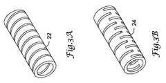
- FIG. 3Ais a plan view of an alternative reinforcing member for a guidewire in accordance with the invention.
- FIG. 3Bis a plan view of an alternative reinforcing member for a guidewire in accordance with the invention.
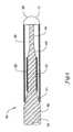
- FIG. 4is a partial cross-sectional view of a variation of the distal portion of a guidewire
- FIG. 4Ais an orthogonal cross-sectional view of the guidewire in FIG. 4 ;
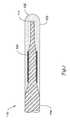
- FIG. 5is a partial cross-sectional view of another embodiment of the distal portion of a guidewire
- FIG. 6is a cross-sectional view of an alternative embodiment of the distal portion of a guidewire in accordance with the invention.
- FIG. 7is a cross-sectional view of a variation of the distal portion of the guidewire in FIG. 6 ;
- FIG. 8is a cross-sectional view of a variation of the distal portion of the guidewire in FIG. 6 ;
- FIG. 9is a cross-sectional view of an alternative embodiment of the distal portion of a guidewire in accordance with the invention.
- FIG. 10is a partial cross-sectional view of another embodiment of the distal portion of a guidewire.
- FIG. 11is a partial cross-sectional view of an alternative embodiment of a guidewire in accordance with the invention.
- Weight percent, percent by weight, wt %, wt-%, % by weight, and the likeare synonyms that refer to the concentration of a substance as the weight of that substance divided by the weight of the composition and multiplied by 100.
- FIG. 1is a schematic plan view of one example embodiment of a guidewire 10 .
- the guidewire 10includes a proximal section 11 defining a proximal end 13 , and a distal section 15 defining a distal end 17 .
- a distal tip 12is located near distal end 17 .
- guidewire 10may include a core member or wire 14 .
- the distal section 15includes a proximal portion 16 and a distal portion 18 .
- Core wire 14can be made of any suitable materials including metals, metal alloys, polymers, or the like, or combinations or mixtures thereof.
- suitable metals and metal alloysinclude stainless steel, such as 304v stainless steel; nickel-titanium alloy, such as linear elastic or superelastic (i.e., pseudo elastic) nitinol, nickel-chromium alloy, nickel-chromium-iron alloy, cobalt alloy, tungsten, tungsten alloy, Elgiloy, MP35N, or the like; or other suitable materials.
- nitinolwas coined by a group of researchers at the United States Naval Ordinance Laboratory (NOL) who were the first to observe the shape memory behavior of this material.
- the word nitinolis an acronym including the chemical symbol for nickel (Ni), the chemical symbol for titanium (Ti), and an acronym identifying the Naval Ordinance Laboratory (NOL).
- nitinol alloyscan include in the range of about 50 to about 60 weight percent nickel, with the remainder being essentially titanium. It should be understood, however, that in other embodiments, the range of weight percent nickel and titanium, and/or other trace elements may vary from these ranges.
- Within the family of commercially available nitinol alloysare categories designated as “superelastic” (i.e., pseudo elastic) and “linear elastic” which, although similar in chemistry, exhibit distinct and useful mechanical properties.
- a superelastic alloyfor example a superelastic Nitinol
- a superelastic alloycan be used to achieve desired properties.
- Such alloystypically display a substantial “superelastic plateau” or “flag region” in its stress/strain curve.
- Such alloyscan be desirable in some embodiments because a suitable superelastic alloy will provide a reinforcing member that exhibits some enhanced ability, relative to some other non-superelastic materials, of substantially recovering its shape without significant plastic deformation, upon the application and release of stress, for example, during placement of the catheter in the body.
- a linear elastic alloyfor example a linear elastic Nitinol
- a linear elastic Nitinolcan be used to achieve desired properties.
- certain linear elastic nitinol alloyscan be generated by the application of cold work, directional stress and heat treatment such that the material fabricated does not display a substantial “superelastic plateau” or “flag region” in its stress/strain curve. Instead, in such embodiments, as recoverable strain increases, the stress continues to increase in a somewhat linear relationship until plastic deformation begins.
- the linear elastic nickel-titanium alloyis an alloy that does not show any martensite/austenite phase changes that are detectable by DSC and DMTA analysis over a large temperature range.
- the mechanical bending properties of such materialare, therefore, generally inert to the effect of temperature over a broad range of temperature.
- the mechanical properties of the alloy at ambient or room temperatureare substantially the same as the mechanical properties at body temperature.
- the use of the linear elastic nickel-titanium alloyallows the reinforcing member to exhibit superior “pushability” around tortuous anatomy.
- a suitable nickel-titanium alloy exhibiting at least some linear elastic propertiesis FHP-NT alloy commercially available from Furukawa Techno Material Co. of Kanagawa, Japan.
- suitable nickel-titanium alloy exhibiting at least some linear elastic propertiesinclude those disclosed in U.S. Pat. Nos. 5,238,004 and 6,508,803, which are incorporated herein by reference.
- portions or all of core wire 14may also be doped with, made of or otherwise include a radiopaque material.
- Radiopaque materialsare understood to be materials capable of producing a relatively bright image on a fluoroscopy screen or another imaging technique during a medical procedure. This relatively bright image aids the user of device 10 in determining its location.
- Some examples of radiopaque materialscan include, but are not limited to, gold, platinum, palladium, tantalum, tungsten alloy, polymer material loaded with a radiopaque filler, and the like.
- radiopaque memberor a series of radiopaque members, such as radiopaque coils, bands, tubes, or other such structures could be attached to the guidewire core wire or incorporated into the core wire by plating, drawing, forging, or ion implantation techniques, and the like.
- a degree of MRI compatibilityis imparted into guidewire 10 .
- core wire 14may be made of a material that does not substantially distort the image and create substantial artifacts (artifacts are gaps in the image).
- Certain ferromagnetic materialsmay not be suitable because they may create artifacts in an MRI image.
- Core wire 14 , or portions thereofmay also be made from a material that the MRI machine can image. Some materials that exhibit these characteristics include, for example, tungsten, Elgiloy, MP35N, nitinol, and the like, and others.
- the entire core wire 14can be made of the same material, or in some embodiments, can include portions or sections made of different materials.
- the material used to construct core wire 14is chosen to impart varying flexibility and stiffness characteristics to different portions of core wire 14 .
- proximal section 11 and distal section 15may be formed of different materials, for example materials having different moduli of elasticity, resulting in a difference in flexibility.
- the material used to construct proximal section 11can be relatively stiff for pushability and torqueability, and the material used to construct distal section 15 can be relatively flexible by comparison for better lateral trackability and steerability.
- proximal section 11can be formed of straightened 304v stainless steel wire or ribbon
- distal section 15can be formed of a straightened super elastic or linear elastic alloy, for example a nickel-titanium alloy wire or ribbon.
- the different portionscan be connected using any suitable connecting techniques.
- the different portions of the core wirecan be connected using welding, soldering, brazing, adhesives, or the like, or combinations thereof.
- some embodimentscan include one or more mechanical connectors or connector assemblies to connect the different portions of the core wire that are made of different materials.
- the connectormay include any structure generally suitable for connecting portions of a guidewire.
- a suitable structureincludes a structure such as a hypotube or a coiled wire which has an inside diameter sized appropriately to receive and connect to the ends of the proximal portion and the distal portion.
- proximal section 11may have a length in the range of about 20 to about 300 centimeters or more and distal section 15 may have a length in the range of about 3 to about 50 centimeters or more. It can be appreciated that alterations in the length of sections 11 / 15 can be made without departing from the spirit of the invention.
- Core wire 14can have a solid cross-section, but in some embodiments, can have a hollow cross-section. In yet other embodiments, core wire 14 can include a combination of areas having solid cross-sections and hollow cross-sections. Moreover, core wire 14 , or portions thereof, can be made of rounded wire, flattened ribbon, or other such structures having various cross-sectional geometries. The cross-sectional geometries along the length of shaft 14 can be constant or can vary. For example, FIG. 2 depicts core wire 14 as having a round cross-sectional shape. It can be appreciated that other cross-sectional shapes or combinations of shapes may be utilized without departing from the spirit of the invention. For example, the cross-sectional shape of core wire 14 may be oval, rectangular, square, polygonal, and the like, or any suitable shape.
- distal section 15may include one or more tapers or tapered regions.
- distal region 18may be tapered and have an initial outside size or diameter that can be substantially the same as the outside diameter of proximal section 11 , which then tapers to a reduced size or diameter.
- distal section 15can have an initial outside diameter that is in the range of about 0.010 inches to about 0.040 inches that tapers to a diameter in the range of about 0.001 inches to about 0.005 inches.
- the tapered regionsmay be linearly tapered, tapered in a curvilinear fashion, uniformly tapered, non-uniformly tapered, or tapered in a step-wise fashion.
- the angle of any such taperscan vary, depending upon the desired flexibility characteristics.
- the length of the tapermay be selected to obtain a more (longer length) or less (shorter length) gradual transition in stiffness.
- FIG. 2depicts distal section 15 of core wire 14 as being tapered, it can be appreciated that essentially any portion of core wire 14 may be tapered and the taper can be in either the proximal or the distal direction.
- the tapered regionmay include one or more portions where the outside diameter is narrowing, for example the tapered portions, and portions where the outside diameter remains essentially constant, for example constant diameter portions.
- the number, arrangement, size, and length of the narrowing and constant diameter portionscan be varied to achieve the desired characteristics, such as flexibility and torque transmission characteristics.
- the narrowing and constant diameter portions as shown in FIG. 2are not intended to be limiting, and alterations of this arrangement can be made without departing from the spirit of the invention.
- the tapered and constant diameter portions of the tapered regionmay be formed by any one of a number of different techniques, for example, by centerless grinding methods, stamping methods, and the like.
- the centerless grinding techniquemay utilize an indexing system employing sensors (e.g., optical/reflective, magnetic) to avoid excessive grinding of the connection.
- the centerless grinding techniquemay utilize a CBN or diamond abrasive grinding wheel that is well shaped and dressed to avoid grabbing the core wire during the grinding process.
- core wire 14can be centerless ground using a Royal Master HI-AC centerless grinder.
- a reinforcing member 20may be disposed about a proximal portion 16 of the distal section 15 of the core wire 14 .
- a distal portion 18 of the distal section 15extends distally beyond the reinforcing member 20 .
- the reinforcing membermay be a tubular segment 20 formed of a variety of materials including metals, metal alloys, polymers, and the like. Some examples of material for use in the tubular segment 20 include stainless steel, nickel-titanium alloy, nickel-chromium alloy, nickel-chromium-iron alloy, cobalt alloy, or other suitable materials.
- the tubular segment 20includes nickel-titanium alloy for its superior characteristics such as pushability, with a preferred embodiment further utilizing a stainless steel as a core member 14 .
- tubular segment 20may include at least one groove or cut 24 .
- the groove or cut 24may enhance the properties, such as flexibility, of the tubular segment 20 .
- the groove or cut 24may extend through substantially the entire thickness of the tube, or the groove or cut 24 may extend only partially through the thickness of the tube (such as a score line).
- a plurality of grooves or cuts 24may be used to acquire the necessary flexibility.
- the groove or cut 22may be helically formed along the length of the tubular segment 20 or a portion thereof.
- the helical groove or cut 22may extend only partially through the thickness of the tube (such as a score line) or may extend through substantially the entire thickness of the tube.
- the pitch of the helical groove or cut 22may be selected in order to provide desired functionality, or the pitch may vary along the length of the tubular segment 20 .
- the tubular segment 20may include one or more additional helical grooves or cuts 22 or a combination of grooves or cuts 24 and helical grooves or cuts 22 . It is understood that the width and depth of the groove or cut 22 , 24 may be of a wide range as may be necessary to attain the desired properties of the tubular segment 20 .
- the groove or cut 22 , 24may be made by any of a variety of techniques known in the art, such as a laser cutter or a plasma cutter.
- an outer memberis disposed about at least a portion of the distal section 15 of the core member 14 .
- the outer membermay extend from the distal end 17 of guidewire 10 to a point proximal of the distal end 17 .
- the outer membermay extend over at least a portion of the reinforcing member, preferably extending substantially over the entire reinforcing member.
- the outer membermay have an outer diameter substantially the same as the diameter of the proximal section 11 of core wire 14 , or the outer diameter of the outer member may be larger or smaller than that of the adjacent portion of the core wire 14 .
- the outer membermay be a coil 30 .
- the coil 30may be disposed about the distal section 15 of the guidewire 10 .
- the coil 30can be formed of a variety of materials including metals, metal alloys, polymers, and the like. Some examples of materials for use in the coil 30 include stainless steel, nickel-chromium alloy, nickel-chromium-iron alloy, cobalt alloy, or other suitable materials. Some additional examples of suitable materials include straightened super elastic or linear elastic alloy (e.g., nickel-titanium) wire, or alternatively, a polymer material, such as a high performance polymer.
- the coil 30 or portions thereofcan be made of, include or be coated with a radiopaque material such as gold, platinum, tungsten, or the like, or alloys thereof.
- the coil 30can be formed of round or flat ribbon ranging in dimensions to achieve the desired flexibility.
- the coil 30can be a round ribbon in the range of about 0.001 inches to about 0.015 inches in diameter, and can have a length in the range of about 0.1 to about 20 inches.
- other dimensionsare contemplated.
- the coil 30can be wrapped in a helical fashion by conventional winding techniques.
- the pitch of adjacent turns of the coil 30may be tightly wrapped so that each turn touches the succeeding turn or the pitch may be set such that the coil 30 is wrapped in an open fashion.
- a distal tip 32may be positioned at the distal end 17 of guidewire 10 .
- the distal tip 32may be a solder, polymer, or other material known in the art.
- the distal tip 32may include a radiopaque material, making the location of the distal tip within a body region more visible when using certain imaging techniques, for example, fluoroscopy techniques. Any suitable radiopaque material known in the art can be used. Some examples include precious metals, tungsten, barium subcarbonate powder, and the like, and mixtures thereof.
- the distal tip 32may be located distal of coil 30 .
- the distal tip, or a portion thereof,may be located within the distal portion of coil 30 .
- FIG. 4A variation of the distal section 15 of guidewire 10 is shown in FIG. 4 .
- the distal section 15 of guidewire 10is substantially the same as in FIG. 2 , except for the relative spacing between the tubular segment 20 and the coil 30 .
- the tubular segment 20is located adjacent to the coil 30 , whereas in FIG. 2A , there is a space between the tubular segment 20 and the coil 30 .
- the relative spacing between the tubular segment 20 and the coil 30may provide unique characteristics of the distal section 15 that may be desirable during a procedure.
- Core wire 14includes a proximal portion 40 , an intermediate portion 42 , and a distal portion 44 .
- a taper 41is located between proximal portion 40 and intermediate portion 42 in order to transition from a first cross-section in proximal portion 40 to a second cross-section in intermediate portion 42 .
- a taper 43is located between intermediate portion 42 and distal portion 44 in order to transition from the second cross-section in intermediate portion 42 to a third cross-section in distal portion 44 .
- the tapering and constant cross-sectional area portions as shown in FIG. 4are not intended to be limiting, and alterations of this arrangement can be made without departing from the spirit of the invention as discussed earlier.
- a reinforcing member 50is disposed about the intermediate portion 42 of the core wire 14 .
- the reinforcing membermay provide desired characteristics in the region of the intermediate portion 42 of the core wire 14 which may be inadequately provided by the material used in that portion of the core wire 14 .
- the core wiremay be stainless steel having superior properties of flexibility and steerability.
- the reinforcing membermay be a nickel-titanium alloy providing enhanced pushability and torqueability to the intermediate portion.
- the distal portion 44may be ribbon shaped providing desired flexibility characteristics at the distal end 17 of the guidewire 10 .
- the distal portion 44may be shape formed prior to a medical procedure to provide a desired curved tip for enhanced navigation through a tortuous vascular system.
- the reinforcing member in FIG. 5is a coil 50 .
- the coil 50may be disposed about the distal section 15 of the guidewire 10 .
- the coil 50can be formed from a variety of materials including metals, metal alloys, polymers, and the like.
- the coil 50may preferably include nickel-titanium alloy.
- Some other examples of material for use in the coil 50include stainless steel, nickel-chromium alloy, nickel-chromium-iron alloy, cobalt alloy, a polymer material such as a high performance polymer, or other suitable materials.
- the coil 50 or portions thereofcan be made of, include or be coated with a radiopaque material such as gold, platinum, tungsten, or the like, or alloys thereof.
- a nickel-titanium alloy coilis used with a stainless steel core 14 .
- the coil 50can be formed of wire ranging in dimensions to achieve the desired flexibility.
- the wirecan be round wire, rectangular wire, or flat ribbon. Wire of other cross-sectional areas is also contemplated in the invention.
- the coil 50can be wrapped in a helical fashion by conventional winding techniques. The pitch of adjacent turns of the coil 50 may be tightly wrapped so that each turn touches the succeeding turn or the pitch may be set such that the coil 50 is wrapped in an open fashion.
- the coil 50may be disposed about the intermediate portion 42 of core wire 14 .
- the coil 50may end proximal of the distal portion 44 of the core wire 14 .
- the coil 50may provide desired characteristics in the region of the intermediate portion 42 of the core wire 14 which may be inadequately provided by the core wire 14 .
- FIG. 6shows an alternative embodiment of the distal section 15 of the guidewire 10 .
- the reinforcing memberis a helically wrapped wire 60 wound about a portion of the distal section 15 of core wire 14 .
- the helically wrapped wire 60may be a single strand wound about the core wire 14 , or may comprise a plurality of wires 60 wound about the core wire 14 .
- a first strandmay be wound in one direction and a second strand wound in an opposing direction.
- wrapping a plurality of wires 60 in the same or similar directionis contemplated within the scope of the invention.
- the helically wrapped wire 60can be round wire, rectangular wire, or flat ribbon. Wire of other cross-sectional areas is also contemplated in the invention.
- the helically wrapped wire 60may be formed from a variety of materials including metals, metal alloys, polymers, fibers, and the like.
- the wire 60may preferably include nickel-titanium alloy. Some other examples of material for use in the wire 60 include stainless steel, nickel-chromium alloy, nickel-chromium-iron alloy, cobalt alloy, a polymer material such as a high performance polymer, or other suitable materials.
- the wire 60 or portions thereofcan be made of, include or be coated with a radiopaque material such as gold, platinum, tungsten, or the like, or alloys thereof.
- a radiopaque materialsuch as gold, platinum, tungsten, or the like, or alloys thereof.
- the helically wrapped wireincludes nickel-titanium alloy, and the core contains stainless steel.
- a polymer jacket tip or combination coil/polymer tipcan be used.
- the polymer jacket tipmay extend over at least a portion of the core wire.
- the outer diameter of the polymer tipmay be substantially the same as the diameter of a region of the core wire, or it may be larger or smaller in diameter.
- a polymer tip having a substantially similar outer diametermay create a smooth transition from a region of the core wire located adjacent to the polymer tip. The smooth transition allows medical devices to be delivered over the guidewire with minimal interference through a transition section, thus increasing efficiency of a medical procedure while reducing the possibility of inadvertent damage to a body region.
- an outer polymer member 170is disposed over a portion of the core wire 114 .
- a polymer tip guidewireis formed by including a polymer sheath 170 extending over at least a portion of the distal section 115 of the core wire 114 , and forms a rounded tip 132 over the distal end 117 of core member 114 .
- the polymer sheath 170can be made from any material that can provide the desired strength, flexibility or other desired characteristics.
- the polymer sheath 170can, in some non-limiting embodiments, have a length that is in the range of about 1.0 inches to about 25.0 inches, an inner diameter that is in the range of about 0.003 inches to about 0.010 inches and an outer diameter that is in the range of about 0.010 inches to about 0.035 inches.
- a polymercan serve several functions, such as improving the flexibility properties of the guidewire assembly.
- Choice of polymers for the sheath or sleeve 150will vary the flexibility of the guidewire. For example, polymers with a low durometer or hardness will make a very flexible or floppy tip. Conversely, polymers with a high durometer will make a tip which is stiffer.
- the use of polymers for the sleevecan also provide a more atraumatic tip for the guidewire. An atraumatic tip is better suited for passing through fragile body passages.
- a polymercan act as a binder for radiopaque materials, as discussed in more detail below.
- suitable materialsinclude polymers, and like material.
- suitable polymer materialinclude any of a broad variety of polymers generally known for use as guidewire polymer sleeves.
- the polymer material usedis a thermoplastic polymer material.
- suitable materialsinclude polyurethane, elastomeric polyamides, block polyamide/ethers (such as PEBAXTM), silicones, and co-polymers.
- the sleevemay be a single polymer, multiple layers, or a blend of polymers.
- suitable polymeric materialsinclude but are not limited to poly(L-lactide) (PLLA), poly(D,L-lactide) (PLA), polyglycolide (PGA), poly(L-lactide-co-D,L-lactide) (PLLA/PLA), poly(L-lactide-co-glycolide) (PLLA/PGA), poly(D, L-lactide-co-glycolide) (PLA/PGA), poly(glycolide-co-trimethylene carbonate) (PGA/PTMC), polyethylene oxide (PEO), polydioxanone (PDS), polycaprolactone (PCL), polyhydroxylbutyrate (PHBT), poly(phosphazene), poly D,L-lactide-co-caprolactone) (PLA/PCL), poly(glycolide-co-caprolactone) (PGA/PCL), polyanhydrides (PAN), poly(ortho esters), poly(phosphate ester), poly(amino acid),
- the sheath 170 or portions thereofcan include or be doped with radiopaque material to make the sheath 170 or portions thereof more visible when using certain imaging techniques, for example fluoroscopy techniques.
- radiopaque materialAny suitable radiopaque material known in the art can be used. Some examples include precious metals, tungsten, barium subcarbonate powder, and the like, and mixtures thereof.
- the polymercan include different sections having different amounts of loading with radiopaque material.
- the sheath or sleeve 150can include a distal section having a higher level of radiopaque material loading, and a proximal section having a correspondingly lower level of loading.
- the sheath 170can be disposed around and attached to the guidewire assembly 110 using any suitable technique for the particular material used.
- the sheath 170can be attached by heating a sleeve of polymer material to a temperature until it is reformed around the guidewire assembly 110 .
- the sheath 170can be attached using heat-shrinking techniques.
- the sheath or sleeve 170can be co-extruded with the core wire 114 .
- the sheath 170can be finished, for example, by a centerless grinding or other method to provide the desired diameter and to provide a smooth outer surface.
- FIG. 8shows an alternative embodiment of a guidewire having a distal section 215 .
- the guidewireincludes a reinforcing member 250 disposed on a tapered portion 242 of the core wire 214 . It is therefore contemplated that the reinforcing member 250 may be located on a portion of the core wire 214 having a variable cross-section.
- the tapered portion 242is located between proximal region 240 and distal region 244 .
- Distal region 244may be of a circular cross-section or may be ribbon shaped.
- Outer polymer layer 270may be disposed over at least a portion of the distal region 215 forming a rounded tip 232 .
- a coilcould overlay the reinforcing member 250 , as in FIG. 2 .
- FIG. 9shows an alternative embodiment of a distal region 315 of a guidewire.
- the guidewireincludes a core wire 314 having a continuous taper from a proximal tapered portion 342 , through a distal tapered portion 344 , to the distal end 317 of the core wire 314 .
- a reinforcing member 350is disposed on at least a portion of the tapered portion 342 , 344 .
- An outer polymer member 370extends over at least a portion of the tapered portion 342 , 344 , and preferably extends to a proximal portion 340 of the core wire 314 .
- FIG. 10combines a reinforcing member comprising a tubular member 420 like that of FIG. 2 with a polymer sleeve 470 like that in FIG. 7 .
- the tubular member 420is disposed on a distal portion 415 of the core wire 414 .
- the tubular member 420may have cuts, grooves, or similar features as disclosed with tubular member 20 .
- FIG. 11depicts an additional embodiment in accordance with the invention.
- Helically wrapped wire 560is disposed along at least a portion of the distal region 515 of core wire 514 .
- helically wrapped wire 560may be a single strand or a plurality of strands.
- helically wrapped wire 560includes a first strand wound about a portion of the core wire 514 and a second strand wound about the portion of the core wire 514 in an opposing direction.
- Polymer sleeve 570is positioned over at least a portion of the distal region 515 .
- the polymer sleeve 570preferably has an outside diameter substantially the same as the diameter of the core wire 514 adjacent the polymer sleeve 570 .
- a coatingfor example a lubricious (e.g., hydrophylic) or other type of coating, may be applied over portions or all of the core wire, reinforcing member, outer member, or other portions of the guidewire.
- Hydrophobic coatingssuch as fluoropolymers provide a dry lubricity which improves guidewire handling and device exchanges. Lubricious coatings improve steerability and improve lesion crossing capability.
- Suitable lubricious polymersare well known in the art and may include hydrophilic polymers such as polyarylene oxides, polyvinylpyrolidones, polyvinylalcohols, hydroxy alkyl cellulosics, algins, saccharides, caprolactones, and the like, and mixtures and combinations thereof. Hydrophilic polymers may be blended among themselves or with formulated amounts of water insoluble compounds (including some polymers) to yield coatings with suitable lubricity, bonding, and solubility. Some other examples of such coatings and materials and methods used to create such coatings can be found in U.S. Pat. Nos. 6,139,510 and 5,772,609, which are incorporated herein by reference. In some embodiments, the more distal portion of the guidewire is coated with a hydrophilic polymer as discussed above, and the more proximal portions are coated with a fluoropolymer, such as polytetrafluoroethylene (PTFE).
- PTFEpolytetrafluoro
- radiopaque markerssuch as radiopaque markers, safety and/or shaping ribbons (coiled or uncoiled), additional coils or reinforcing members, and the like, may be incorporated into the guidewire construction.
Landscapes
- Health & Medical Sciences (AREA)
- Life Sciences & Earth Sciences (AREA)
- Biophysics (AREA)
- Pulmonology (AREA)
- Engineering & Computer Science (AREA)
- Anesthesiology (AREA)
- Biomedical Technology (AREA)
- Heart & Thoracic Surgery (AREA)
- Hematology (AREA)
- Animal Behavior & Ethology (AREA)
- General Health & Medical Sciences (AREA)
- Public Health (AREA)
- Veterinary Medicine (AREA)
- Media Introduction/Drainage Providing Device (AREA)
Abstract
Description
Claims (20)
Priority Applications (5)
| Application Number | Priority Date | Filing Date | Title |
|---|---|---|---|
| US10/667,043US7785273B2 (en) | 2003-09-22 | 2003-09-22 | Guidewire with reinforcing member |
| CA2538692ACA2538692C (en) | 2003-09-22 | 2004-09-16 | Guidewire with reinforcing member |
| EP04784168AEP1673130B1 (en) | 2003-09-22 | 2004-09-16 | Guidewire with reinforcing member |
| PCT/US2004/030216WO2005030311A1 (en) | 2003-09-22 | 2004-09-16 | Guidewire with reinforcing member |
| JP2006528060AJP4833845B2 (en) | 2003-09-22 | 2004-09-16 | Guide wire with reinforcing member |
Applications Claiming Priority (1)
| Application Number | Priority Date | Filing Date | Title |
|---|---|---|---|
| US10/667,043US7785273B2 (en) | 2003-09-22 | 2003-09-22 | Guidewire with reinforcing member |
Publications (2)
| Publication Number | Publication Date |
|---|---|
| US20050065456A1 US20050065456A1 (en) | 2005-03-24 |
| US7785273B2true US7785273B2 (en) | 2010-08-31 |
Family
ID=34313249
Family Applications (1)
| Application Number | Title | Priority Date | Filing Date |
|---|---|---|---|
| US10/667,043Expired - Fee RelatedUS7785273B2 (en) | 2003-09-22 | 2003-09-22 | Guidewire with reinforcing member |
Country Status (5)
| Country | Link |
|---|---|
| US (1) | US7785273B2 (en) |
| EP (1) | EP1673130B1 (en) |
| JP (1) | JP4833845B2 (en) |
| CA (1) | CA2538692C (en) |
| WO (1) | WO2005030311A1 (en) |
Cited By (29)
| Publication number | Priority date | Publication date | Assignee | Title |
|---|---|---|---|---|
| US20100318065A1 (en)* | 2009-06-16 | 2010-12-16 | Asahi Intecc Co., Ltd. | Medical guidewire |
| US20120316543A1 (en)* | 2010-12-28 | 2012-12-13 | Olympus Medical Systems Corp. | Treatment device for endoscope |
| US20130204163A1 (en)* | 2012-02-02 | 2013-08-08 | Abbott Cardiovascular Systems, Inc. | Guide wire core wire made from a substantially titanium-free alloy for enhanced guide wire steering response |
| US20140358169A1 (en)* | 2013-05-31 | 2014-12-04 | Fmd Co., Ltd. | Medical guide wire |
| US9636485B2 (en) | 2013-01-17 | 2017-05-02 | Abbott Cardiovascular Systems, Inc. | Methods for counteracting rebounding effects during solid state resistance welding of dissimilar materials |
| US20180015262A1 (en)* | 2016-07-18 | 2018-01-18 | Scientia Vascular | Guidewire devices having distally extending coils and shapeable tips |
| US9950137B2 (en) | 2009-04-03 | 2018-04-24 | Scientia Vascular, Llc | Micro-fabricated guidewire devices formed with hybrid materials |
| US10173052B2 (en) | 2016-03-18 | 2019-01-08 | Teleflex Innovations S.À.R.L. | Pacing guidewire |
| US10232141B2 (en) | 2008-12-08 | 2019-03-19 | Scientia Vascular, Llc | Micro-cutting systems for forming cuts in products |
| US10252024B2 (en) | 2016-04-05 | 2019-04-09 | Stryker Corporation | Medical devices and methods of manufacturing same |
| US10363389B2 (en) | 2009-04-03 | 2019-07-30 | Scientia Vascular, Llc | Micro-fabricated guidewire devices having varying diameters |
| US10391282B2 (en) | 2014-07-08 | 2019-08-27 | Teleflex Innovations S.À.R.L. | Guidewires and methods for percutaneous occlusion crossing |
| US10722252B2 (en) | 2017-10-26 | 2020-07-28 | Teleflex Life Sciences Limited | Subintimal catheter device, assembly and related methods |
| US10821268B2 (en) | 2016-09-14 | 2020-11-03 | Scientia Vascular, Llc | Integrated coil vascular devices |
| US11052228B2 (en) | 2016-07-18 | 2021-07-06 | Scientia Vascular, Llc | Guidewire devices having shapeable tips and bypass cuts |
| US11202888B2 (en) | 2017-12-03 | 2021-12-21 | Cook Medical Technologies Llc | MRI compatible interventional wireguide |
| US11278701B2 (en) | 2016-10-13 | 2022-03-22 | Lake Region Manufacturing, Inc. | Apparatus including multiple joined hypotubes and method of making same |
| US11305095B2 (en) | 2018-02-22 | 2022-04-19 | Scientia Vascular, Llc | Microfabricated catheter having an intermediate preferred bending section |
| US11369351B2 (en) | 2017-05-26 | 2022-06-28 | Scientia Vascular, Inc. | Micro-fabricated medical device having a non-helical cut arrangement |
| US11406791B2 (en) | 2009-04-03 | 2022-08-09 | Scientia Vascular, Inc. | Micro-fabricated guidewire devices having varying diameters |
| US11452541B2 (en) | 2016-12-22 | 2022-09-27 | Scientia Vascular, Inc. | Intravascular device having a selectively deflectable tip |
| US12011555B2 (en) | 2019-01-15 | 2024-06-18 | Scientia Vascular, Inc. | Guidewire with core centering mechanism |
| US12178975B2 (en) | 2020-01-23 | 2024-12-31 | Scientia Vascular, Inc. | Guidewire having enlarged, micro-fabricated distal section |
| US12220538B2 (en) | 2008-12-08 | 2025-02-11 | Scientia Vascular, Inc. | Micro-fabricated intravascular devices having varying diameters |
| US12296112B2 (en) | 2020-10-05 | 2025-05-13 | Scientia Vascular, Inc. | Microfabricated catheter devices with high axial strength |
| US12343479B2 (en) | 2016-02-24 | 2025-07-01 | Incept, Llc | Neurovascular catheter |
| US12343485B2 (en) | 2020-01-23 | 2025-07-01 | Scientia Vascular, Inc. | High torque guidewire device |
| US12364840B2 (en) | 2016-07-29 | 2025-07-22 | Cephea Valve Technologies, Inc. | Mechanical interlock for catheters |
| US12440332B2 (en) | 2021-08-11 | 2025-10-14 | Cephea Valve Technologies, Inc. | Systems and methods for loading and deploying an intravascular device |
Families Citing this family (44)
| Publication number | Priority date | Publication date | Assignee | Title |
|---|---|---|---|---|
| US8608703B2 (en)* | 2007-06-12 | 2013-12-17 | Medrad, Inc. | Infusion flow guidewire system |
| US8876772B2 (en)* | 2005-11-16 | 2014-11-04 | Boston Scientific Scimed, Inc. | Variable stiffness shaft |
| US8292827B2 (en)* | 2005-12-12 | 2012-10-23 | Boston Scientific Scimed, Inc. | Micromachined medical devices |
| US20080114435A1 (en)* | 2006-03-07 | 2008-05-15 | Med Institute, Inc. | Flexible delivery system |
| US8567265B2 (en)* | 2006-06-09 | 2013-10-29 | Endosense, SA | Triaxial fiber optic force sensing catheter |
| DE102006047675A1 (en)* | 2006-09-28 | 2008-04-03 | Epflex Feinwerktechnik Gmbh | Guidewire with core and distal sheath |
| US8556914B2 (en)* | 2006-12-15 | 2013-10-15 | Boston Scientific Scimed, Inc. | Medical device including structure for crossing an occlusion in a vessel |
| US7744545B2 (en)* | 2006-12-28 | 2010-06-29 | Terumo Kabushiki Kaisha | Guide wire |
| JP5148936B2 (en)* | 2006-12-28 | 2013-02-20 | テルモ株式会社 | Guide wire |
| US20080262474A1 (en)* | 2007-04-20 | 2008-10-23 | Boston Scientific Scimed, Inc. | Medical device |
| JP2010524631A (en)* | 2007-04-23 | 2010-07-22 | インターヴェンショナル アンド サージカル イノヴェイションズ リミテッド ライアビリティ カンパニー | Guidewire with adjustable stiffness |
| US9387308B2 (en) | 2007-04-23 | 2016-07-12 | Cardioguidance Biomedical, Llc | Guidewire with adjustable stiffness |
| US20090118675A1 (en)* | 2007-11-02 | 2009-05-07 | Boston Scientific Scimed, Inc. | Elongate medical device with a shapeable tip |
| US20090157048A1 (en)* | 2007-12-18 | 2009-06-18 | Boston Scientific Scimed, Inc. | Spiral cut hypotube |
| US8460213B2 (en) | 2008-01-03 | 2013-06-11 | Boston Scientific Scimed, Inc. | Cut tubular members for a medical device and methods for making and using the same |
| JP2012005520A (en)* | 2010-06-22 | 2012-01-12 | Asahi Intecc Co Ltd | Medical guide wire |
| JP2012040145A (en)* | 2010-08-18 | 2012-03-01 | Terumo Corp | Medical tube protective cover |
| US8795202B2 (en)* | 2011-02-04 | 2014-08-05 | Boston Scientific Scimed, Inc. | Guidewires and methods for making and using the same |
| JP5360840B2 (en)* | 2011-03-31 | 2013-12-04 | 朝日インテック株式会社 | Guide wire |
| JP2013094339A (en)* | 2011-10-31 | 2013-05-20 | Asahi Intecc Co Ltd | Guide wire |
| JP6179995B2 (en)* | 2011-12-05 | 2017-08-16 | ストライカー コーポレイションStryker Corporation | Reinforced stretch medical device and manufacturing method |
| JP5652884B2 (en)* | 2012-07-27 | 2015-01-14 | 朝日インテック株式会社 | Guide wire |
| EP2922593B1 (en) | 2012-11-21 | 2020-04-08 | Concert Medical, LLC | Preformed guidewire |
| JP6066477B2 (en)* | 2013-01-17 | 2017-01-25 | 日本ライフライン株式会社 | Medical guidewire |
| JP2014147458A (en) | 2013-01-31 | 2014-08-21 | Asahi Intecc Co Ltd | Slit pipe and guide wire with the same |
| CN103961785A (en)* | 2013-01-31 | 2014-08-06 | 朝日英达科株式会社 | Slitted pipe and guide wire using the same |
| JP2014147459A (en) | 2013-01-31 | 2014-08-21 | Asahi Intecc Co Ltd | Slit pipe and guide wire with the same |
| EP2968855B1 (en)* | 2013-03-12 | 2020-12-30 | Lake Region Manufacturing, Inc. d/b/a Lake Region Medical | Multiconductor guidewire with chordal surface |
| JP6069532B2 (en)* | 2013-03-13 | 2017-02-01 | セント ジュード メディカル コーディネイション センター ベーファウベーアー | Sensor guide wire with shape memory tip |
| WO2014181427A1 (en)* | 2013-05-09 | 2014-11-13 | テルモ株式会社 | Guide wire and method for producing same |
| WO2015080948A1 (en)* | 2013-11-26 | 2015-06-04 | Boston Scientific Scimed, Inc. | Medical devices for accessing body lumens |
| US10806905B2 (en)* | 2014-08-05 | 2020-10-20 | Cardiovascular Systems, Inc. | Reformable guidewire tip |
| USD743007S1 (en) | 2014-12-01 | 2015-11-10 | Asahi Intecc Co., Ltd. | Slitted pipe |
| US11801368B2 (en)* | 2017-05-25 | 2023-10-31 | C.R. Bard, Inc. | Guidewire |
| US20190060618A1 (en)* | 2017-08-25 | 2019-02-28 | Acclarent, Inc. | Core wire assembly for guidewire |
| JP6864110B2 (en)* | 2017-10-12 | 2021-04-21 | 朝日インテック株式会社 | Guide wire |
| WO2019073571A1 (en) | 2017-10-12 | 2019-04-18 | 朝日インテック株式会社 | Guide wire |
| KR20200071749A (en)* | 2018-05-09 | 2020-06-19 | 아사히 인텍크 가부시키가이샤 | Medical tube |
| JP7364369B2 (en)* | 2019-06-21 | 2023-10-18 | 朝日インテック株式会社 | guide wire |
| CN115697458A (en)* | 2020-06-02 | 2023-02-03 | 尼普洛株式会社 | Guide wire |
| CN111760169B (en)* | 2020-07-21 | 2024-09-03 | 苏州茵络医疗器械有限公司 | Highly resilient guidewire |
| JP2023002009A (en)* | 2021-06-22 | 2023-01-10 | 朝日インテック株式会社 | multilayer coil body |
| US20240009430A1 (en)* | 2022-07-08 | 2024-01-11 | Abbott Cardiovascular Systems Inc. | Guidewire core having non-round cross-sections |
| WO2024026276A2 (en)* | 2022-07-25 | 2024-02-01 | Terumo Corporation | Implant delivery device |
Citations (111)
| Publication number | Priority date | Publication date | Assignee | Title |
|---|---|---|---|---|
| US3174851A (en) | 1961-12-01 | 1965-03-23 | William J Buehler | Nickel-base alloys |
| US3351463A (en) | 1965-08-20 | 1967-11-07 | Alexander G Rozner | High strength nickel-base alloys |
| US3753700A (en) | 1970-07-02 | 1973-08-21 | Raychem Corp | Heat recoverable alloy |
| US4080706A (en) | 1975-04-22 | 1978-03-28 | Medrad, Inc. | Method of manufacturing catheter guidewire |
| US4456017A (en) | 1982-11-22 | 1984-06-26 | Cordis Corporation | Coil spring guide with deflectable tip |
| US4538622A (en) | 1983-11-10 | 1985-09-03 | Advanced Cardiovascular Systems, Inc. | Guide wire for catheters |
| US4748986A (en) | 1985-11-26 | 1988-06-07 | Advanced Cardiovascular Systems, Inc. | Floppy guide wire with opaque tip |
| EP0274412A2 (en) | 1987-01-06 | 1988-07-13 | C.R. Bard, Inc. | Dual coil steerable guidewire |
| US4813434A (en) | 1987-02-17 | 1989-03-21 | Medtronic Versaflex, Inc. | Steerable guidewire with deflectable tip |
| US4846186A (en) | 1988-01-12 | 1989-07-11 | Cordis Corporation | Flexible guidewire |
| US4884579A (en) | 1988-04-18 | 1989-12-05 | Target Therapeutics | Catheter guide wire |
| US4925445A (en) | 1983-09-16 | 1990-05-15 | Fuji Terumo Co., Ltd. | Guide wire for catheter |
| EP0386921A2 (en) | 1989-03-02 | 1990-09-12 | Microspring Company, Inc. | Torque transmitter |
| US4984581A (en) | 1988-10-12 | 1991-01-15 | Flexmedics Corporation | Flexible guide having two-way shape memory alloy |
| US5025799A (en) | 1987-05-13 | 1991-06-25 | Wilson Bruce C | Steerable memory alloy guide wires |
| US5069226A (en) | 1989-04-28 | 1991-12-03 | Tokin Corporation | Catheter guidewire with pseudo elastic shape memory alloy |
| US5095915A (en) | 1990-03-19 | 1992-03-17 | Target Therapeutics | Guidewire with flexible distal tip |
| US5102403A (en) | 1990-06-18 | 1992-04-07 | Eckhard Alt | Therapeutic medical instrument for insertion into body |
| US5109867A (en) | 1991-04-19 | 1992-05-05 | Target Therapeutics | Extendable guidewire assembly |
| US5111829A (en) | 1989-06-28 | 1992-05-12 | Boston Scientific Corporation | Steerable highly elongated guidewire |
| EP0491349A2 (en) | 1990-12-18 | 1992-06-24 | Advanced Cardiovascular Systems, Inc. | Superelastic guiding member |
| US5133364A (en) | 1988-06-13 | 1992-07-28 | C. R. Bard, Inc. | Guidewire extension with self-latching detachable connector |
| US5154705A (en) | 1987-09-30 | 1992-10-13 | Lake Region Manufacturing Co., Inc. | Hollow lumen cable apparatus |
| US5165421A (en) | 1987-09-30 | 1992-11-24 | Lake Region Manufacturing Co., Inc. | Hollow lumen cable apparatus |
| US5213111A (en) | 1991-07-10 | 1993-05-25 | Cook Incorporated | Composite wire guide construction |
| US5230348A (en) | 1990-10-12 | 1993-07-27 | Nippon Seisen Co., Ltd. | Guide wire for a catheter |
| US5238004A (en) | 1990-04-10 | 1993-08-24 | Boston Scientific Corporation | High elongation linear elastic guidewire |
| US5242759A (en) | 1991-05-21 | 1993-09-07 | Cook Incorporated | Joint, a laminate, and a method of preparing a nickel-titanium alloy member surface for bonding to another layer of metal |
| US5253653A (en) | 1991-10-31 | 1993-10-19 | Boston Scientific Corp. | Fluoroscopically viewable guidewire for catheters |
| USRE34466E (en) | 1987-12-23 | 1993-12-07 | Advanced Cardiovascular Systems, Inc. | Extendable guidewire for cardiovascular procedures |
| US5273052A (en) | 1992-01-08 | 1993-12-28 | Danforth Biomedical, Incorporated | Guidewire with reversible contact seal for releasable securement to catheter |
| US5275173A (en) | 1991-08-26 | 1994-01-04 | Target Therapeutics, Inc. | Extendable guidewire assembly |
| US5312356A (en) | 1989-05-22 | 1994-05-17 | Target Therapeutics | Catheter with low-friction distal segment |
| US5333620A (en) | 1991-10-30 | 1994-08-02 | C. R. Bard, Inc. | High performance plastic coated medical guidewire |
| US5341818A (en) | 1992-12-22 | 1994-08-30 | Advanced Cardiovascular Systems, Inc. | Guidewire with superelastic distal portion |
| US5345945A (en) | 1990-08-29 | 1994-09-13 | Baxter International Inc. | Dual coil guidewire with radiopaque distal tip |
| US5358796A (en) | 1991-04-09 | 1994-10-25 | The Furukawa Electric Co., Ltd. | Joined parts of Ni-Ti alloys with different metals and joining method therefor |
| US5365943A (en) | 1993-03-12 | 1994-11-22 | C. R. Bard, Inc. | Anatomically matched steerable PTCA guidewire |
| US5365942A (en) | 1990-06-04 | 1994-11-22 | C. R. Bard, Inc. | Guidewire tip construction |
| US5402799A (en) | 1993-06-29 | 1995-04-04 | Cordis Corporation | Guidewire having flexible floppy tip |
| US5409015A (en) | 1993-05-11 | 1995-04-25 | Target Therapeutics, Inc. | Deformable tip super elastic guidewire |
| US5415633A (en) | 1993-07-28 | 1995-05-16 | Active Control Experts, Inc. | Remotely steered catheterization device |
| US5421349A (en) | 1994-06-16 | 1995-06-06 | Cordis Corporation | Atraumatic proximal guidewire end |
| US5429139A (en) | 1993-05-19 | 1995-07-04 | Schneider (Europe) A.G. | Guide wire |
| US5433200A (en) | 1990-07-09 | 1995-07-18 | Lake Region Manufacturing, Inc. | Low profile, coated, steerable guide wire |
| US5437288A (en) | 1992-09-04 | 1995-08-01 | Mayo Foundation For Medical Education And Research | Flexible catheter guidewire |
| US5452726A (en) | 1991-06-18 | 1995-09-26 | Scimed Life Systems, Inc. | Intravascular guide wire and method for manufacture thereof |
| US5488959A (en) | 1993-12-27 | 1996-02-06 | Cordis Corporation | Medical guidewire and welding process |
| US5497785A (en) | 1994-07-27 | 1996-03-12 | Cordis Corporation | Catheter advancing guidewire and method for making same |
| US5507301A (en) | 1993-11-19 | 1996-04-16 | Advanced Cardiovascular Systems, Inc. | Catheter and guidewire system with flexible distal portions |
| US5520194A (en) | 1993-12-07 | 1996-05-28 | Asahi Intecc Co., Ltd. | Guide wire for medical purpose and manufacturing process of coil thereof |
| US5551444A (en) | 1995-05-31 | 1996-09-03 | Radius Medical Technologies, Inc. | Flexible guidewire with radiopaque outer coil and non-radiopaque inner coil |
| US5573520A (en) | 1991-09-05 | 1996-11-12 | Mayo Foundation For Medical Education And Research | Flexible tubular device for use in medical applications |
| US5596996A (en)* | 1995-03-30 | 1997-01-28 | Medtronic, Inc. | High support nitinol tube guidewire with plastic plug transition |
| US5637089A (en) | 1990-12-18 | 1997-06-10 | Advanced Cardiovascular Systems, Inc. | Superelastic guiding member |
| US5640970A (en)* | 1995-04-26 | 1997-06-24 | Cordis Corporation | Guidewire having a controlled radiopacity tip |
| US5651373A (en) | 1993-09-24 | 1997-07-29 | Cardiometrics, Inc. | Extension device, assembly thereof, heater for use therewith and method |
| US5664580A (en) | 1995-01-31 | 1997-09-09 | Microvena Corporation | Guidewire having bimetallic coil |
| US5666969A (en) | 1994-05-18 | 1997-09-16 | Scimed Life Systems, Inc. | Guidewire having multiple radioscopic coils |
| EP0806220A2 (en) | 1996-04-30 | 1997-11-12 | Target Therapeutics, Inc. | Composite endovascular guidewire |
| US5697380A (en)* | 1996-01-11 | 1997-12-16 | Intella Interventional Systems, Inc. | Guide wire having distal extremity with adjustable support characteristic and method |
| US5720300A (en) | 1993-11-10 | 1998-02-24 | C. R. Bard, Inc. | High performance wires for use in medical devices and alloys therefor |
| US5724989A (en) | 1995-06-20 | 1998-03-10 | The Microspring Company, Inc. | Radiopaque medical devices |
| EP0838230A2 (en) | 1996-10-22 | 1998-04-29 | Terumo Kabushiki Kaisha | Guide wire |
| US5749837A (en) | 1993-05-11 | 1998-05-12 | Target Therapeutics, Inc. | Enhanced lubricity guidewire |
| US5769796A (en) | 1993-05-11 | 1998-06-23 | Target Therapeutics, Inc. | Super-elastic composite guidewire |
| US5772641A (en) | 1995-12-12 | 1998-06-30 | Medi-Dyne Inc. | Overlapping welds for catheter constructions |
| US5772609A (en) | 1993-05-11 | 1998-06-30 | Target Therapeutics, Inc. | Guidewire with variable flexibility due to polymeric coatings |
| US5782741A (en) | 1996-11-12 | 1998-07-21 | Guidant Coropration | Two-stage treatment wire |
| US5782776A (en) | 1994-05-11 | 1998-07-21 | Schneider A.G. | Guidewire attachment assembly |
| US5797857A (en) | 1993-12-24 | 1998-08-25 | Terumo Kabushiki Kaisha | Guide wire |
| US5813997A (en) | 1994-10-28 | 1998-09-29 | Intelliwire, Inc. | Guide wire with deflectable tip and method |
| US5820571A (en) | 1996-06-24 | 1998-10-13 | C. R. Bard, Inc. | Medical backloading wire |
| US5833631A (en) | 1996-06-28 | 1998-11-10 | Target Therapeutics, Inc. | Fiber tip guidewire |
| US5836893A (en) | 1996-03-08 | 1998-11-17 | Scimed Life Systems, Inc. | Intravascular guidewire |
| US5865768A (en) | 1996-09-30 | 1999-02-02 | Medtronic, Inc. | Guide wire |
| US5876356A (en) | 1997-04-02 | 1999-03-02 | Cordis Corporation | Superelastic guidewire with a shapeable tip |
| US5902254A (en) | 1996-07-29 | 1999-05-11 | The Nemours Foundation | Cathether guidewire |
| US5916166A (en) | 1996-11-19 | 1999-06-29 | Interventional Technologies, Inc. | Medical guidewire with fully hardened core |
| US5916178A (en)* | 1995-03-30 | 1999-06-29 | Medtronic, Inc. | Steerable high support guidewire with thin wall nitinol tube |
| US5951496A (en) | 1996-05-03 | 1999-09-14 | Schneider (Europe) Gmbh | Guide wire and method of producing a guide wire |
| US5954672A (en) | 1997-05-21 | 1999-09-21 | Schneider (Europe) Gmbh | Controlled gap guidewire |
| US5957903A (en) | 1991-10-15 | 1999-09-28 | Advanced Cardiovascular Systems, Inc. | Variable stiffness guidewire |
| US5980471A (en) | 1997-10-10 | 1999-11-09 | Advanced Cardiovascular System, Inc. | Guidewire with tubular connector |
| WO2000040286A1 (en) | 1998-12-30 | 2000-07-13 | Advanced Cardiovascular Systems, Inc. | Vapor deposition coated guidewire |
| US6106488A (en) | 1998-08-11 | 2000-08-22 | Scimed Life Systems, Inc. | Flexural rigidity profile guidewire tip |
| US6132388A (en) | 1997-10-16 | 2000-10-17 | Scimed Life Systems, Inc. | Guide wire tip |
| US6139510A (en) | 1994-05-11 | 2000-10-31 | Target Therapeutics Inc. | Super elastic alloy guidewire |
| US6183420B1 (en) | 1997-06-20 | 2001-02-06 | Medtronic Ave, Inc. | Variable stiffness angioplasty guide wire |
| US6203505B1 (en) | 1998-06-05 | 2001-03-20 | Advanced Cardiovascular Systems, Inc. | Guidewires having a vapor deposited primer coat |
| US6210395B1 (en) | 1987-09-30 | 2001-04-03 | Lake Region Mfg., Inc. | Hollow lumen cable apparatus |
| USRE37148E1 (en) | 1990-06-04 | 2001-04-24 | Medtronic Ave, Inc. | Guidewire tip construction |
| US6245030B1 (en) | 1998-03-04 | 2001-06-12 | C. R. Bard, Inc. | Flexible kink resistant, low friction guidewire with formable tip, and method for making same |
| US6251085B1 (en) | 1997-07-04 | 2001-06-26 | Olympus Optical Co., Ltd. | Medical guidewire |
| US6306105B1 (en) | 1998-05-14 | 2001-10-23 | Scimed Life Systems, Inc. | High performance coil wire |
| US20020013540A1 (en) | 1999-12-22 | 2002-01-31 | Jacobsen Stephen C. | Coronary guidewire system |
| US6352515B1 (en) | 1999-12-13 | 2002-03-05 | Advanced Cardiovascular Systems, Inc. | NiTi alloyed guidewires |
| US20020042582A1 (en)* | 2000-10-05 | 2002-04-11 | Scimed Life Systems, Inc. | Guidewire having a marker segment for length assessment |
| US6387060B1 (en) | 1998-06-17 | 2002-05-14 | Advanced Cardiovascular Systems, Inc. | Composite radiopaque intracorporeal product |
| US6410886B1 (en) | 1997-07-10 | 2002-06-25 | Nitinol Technologies, Inc. | Nitinol heater elements |
| US6428489B1 (en) | 1995-12-07 | 2002-08-06 | Precision Vascular Systems, Inc. | Guidewire system |
| US20020183654A1 (en)* | 2001-05-30 | 2002-12-05 | Scimed Life Systems, Inc. | Distal tip portion for a guide wire |
| US6508803B1 (en) | 1998-11-06 | 2003-01-21 | Furukawa Techno Material Co., Ltd. | Niti-type medical guide wire and method of producing the same |
| US20030069520A1 (en) | 2001-10-05 | 2003-04-10 | Scimed Life Systems, Inc. | Guidewire with stiffness blending connection |
| US20030181828A1 (en)* | 2002-01-28 | 2003-09-25 | Katsuharu Fujimoto | Guide wire |
| US20040064069A1 (en)* | 2002-09-30 | 2004-04-01 | Reynolds Brian R. | Medical device with support member |
| US20040122340A1 (en)* | 2002-12-23 | 2004-06-24 | Anthony Vrba | Guidewire tip construction |
| US20050038359A1 (en)* | 2003-07-17 | 2005-02-17 | Terumo Kabushiki Kaisha | Guide wire |
| US20050054952A1 (en)* | 2003-09-05 | 2005-03-10 | Scimed Life Systems, Inc. | Elongated medical device for intracorporal use |
| US6887235B2 (en)* | 1999-03-24 | 2005-05-03 | Micrus Corporation | Variable stiffness heating catheter |
| US7182735B2 (en)* | 2003-02-26 | 2007-02-27 | Scimed Life Systems, Inc. | Elongated intracorporal medical device |
Family Cites Families (1)
| Publication number | Priority date | Publication date | Assignee | Title |
|---|---|---|---|---|
| US7883474B1 (en)* | 1993-05-11 | 2011-02-08 | Target Therapeutics, Inc. | Composite braided guidewire |
- 2003
- 2003-09-22USUS10/667,043patent/US7785273B2/ennot_activeExpired - Fee Related
- 2004
- 2004-09-16CACA2538692Apatent/CA2538692C/ennot_activeExpired - Fee Related
- 2004-09-16JPJP2006528060Apatent/JP4833845B2/ennot_activeExpired - Fee Related
- 2004-09-16EPEP04784168Apatent/EP1673130B1/ennot_activeExpired - Lifetime
- 2004-09-16WOPCT/US2004/030216patent/WO2005030311A1/enactiveApplication Filing
Patent Citations (126)
| Publication number | Priority date | Publication date | Assignee | Title |
|---|---|---|---|---|
| US3174851A (en) | 1961-12-01 | 1965-03-23 | William J Buehler | Nickel-base alloys |
| US3351463A (en) | 1965-08-20 | 1967-11-07 | Alexander G Rozner | High strength nickel-base alloys |
| US3753700A (en) | 1970-07-02 | 1973-08-21 | Raychem Corp | Heat recoverable alloy |
| US4080706A (en) | 1975-04-22 | 1978-03-28 | Medrad, Inc. | Method of manufacturing catheter guidewire |
| US4456017A (en) | 1982-11-22 | 1984-06-26 | Cordis Corporation | Coil spring guide with deflectable tip |
| US4925445A (en) | 1983-09-16 | 1990-05-15 | Fuji Terumo Co., Ltd. | Guide wire for catheter |
| US4538622A (en) | 1983-11-10 | 1985-09-03 | Advanced Cardiovascular Systems, Inc. | Guide wire for catheters |
| US4748986A (en) | 1985-11-26 | 1988-06-07 | Advanced Cardiovascular Systems, Inc. | Floppy guide wire with opaque tip |
| EP0274412A2 (en) | 1987-01-06 | 1988-07-13 | C.R. Bard, Inc. | Dual coil steerable guidewire |
| US4763647A (en) | 1987-01-06 | 1988-08-16 | C. R. Bard, Inc. | Dual coil steerable guidewire |
| US4813434A (en) | 1987-02-17 | 1989-03-21 | Medtronic Versaflex, Inc. | Steerable guidewire with deflectable tip |
| US5025799A (en) | 1987-05-13 | 1991-06-25 | Wilson Bruce C | Steerable memory alloy guide wires |
| US5154705A (en) | 1987-09-30 | 1992-10-13 | Lake Region Manufacturing Co., Inc. | Hollow lumen cable apparatus |
| US6210395B1 (en) | 1987-09-30 | 2001-04-03 | Lake Region Mfg., Inc. | Hollow lumen cable apparatus |
| US5165421A (en) | 1987-09-30 | 1992-11-24 | Lake Region Manufacturing Co., Inc. | Hollow lumen cable apparatus |
| USRE34466E (en) | 1987-12-23 | 1993-12-07 | Advanced Cardiovascular Systems, Inc. | Extendable guidewire for cardiovascular procedures |
| US4846186A (en) | 1988-01-12 | 1989-07-11 | Cordis Corporation | Flexible guidewire |
| US4884579A (en) | 1988-04-18 | 1989-12-05 | Target Therapeutics | Catheter guide wire |
| US5133364A (en) | 1988-06-13 | 1992-07-28 | C. R. Bard, Inc. | Guidewire extension with self-latching detachable connector |
| US4984581A (en) | 1988-10-12 | 1991-01-15 | Flexmedics Corporation | Flexible guide having two-way shape memory alloy |
| EP0386921A2 (en) | 1989-03-02 | 1990-09-12 | Microspring Company, Inc. | Torque transmitter |
| US5069226A (en) | 1989-04-28 | 1991-12-03 | Tokin Corporation | Catheter guidewire with pseudo elastic shape memory alloy |
| US5312356A (en) | 1989-05-22 | 1994-05-17 | Target Therapeutics | Catheter with low-friction distal segment |
| US5111829A (en) | 1989-06-28 | 1992-05-12 | Boston Scientific Corporation | Steerable highly elongated guidewire |
| US5095915A (en) | 1990-03-19 | 1992-03-17 | Target Therapeutics | Guidewire with flexible distal tip |
| US5599492A (en) | 1990-03-19 | 1997-02-04 | Target Therapeutics, Inc. | Method for making a guidewire with a flexible distal tip |
| US5238004A (en) | 1990-04-10 | 1993-08-24 | Boston Scientific Corporation | High elongation linear elastic guidewire |
| US5365942A (en) | 1990-06-04 | 1994-11-22 | C. R. Bard, Inc. | Guidewire tip construction |
| USRE37148E1 (en) | 1990-06-04 | 2001-04-24 | Medtronic Ave, Inc. | Guidewire tip construction |
| US5102403A (en) | 1990-06-18 | 1992-04-07 | Eckhard Alt | Therapeutic medical instrument for insertion into body |
| US5433200A (en) | 1990-07-09 | 1995-07-18 | Lake Region Manufacturing, Inc. | Low profile, coated, steerable guide wire |
| US5345945A (en) | 1990-08-29 | 1994-09-13 | Baxter International Inc. | Dual coil guidewire with radiopaque distal tip |
| US5230348A (en) | 1990-10-12 | 1993-07-27 | Nippon Seisen Co., Ltd. | Guide wire for a catheter |
| EP0491349A2 (en) | 1990-12-18 | 1992-06-24 | Advanced Cardiovascular Systems, Inc. | Superelastic guiding member |
| US5637089A (en) | 1990-12-18 | 1997-06-10 | Advanced Cardiovascular Systems, Inc. | Superelastic guiding member |
| US5411476A (en) | 1990-12-18 | 1995-05-02 | Advanced Cardiovascular Systems, Inc. | Superelastic guiding member |
| US6165292A (en) | 1990-12-18 | 2000-12-26 | Advanced Cardiovascular Systems, Inc. | Superelastic guiding member |
| US5358796A (en) | 1991-04-09 | 1994-10-25 | The Furukawa Electric Co., Ltd. | Joined parts of Ni-Ti alloys with different metals and joining method therefor |
| US5368661A (en) | 1991-04-09 | 1994-11-29 | The Furukawa Electric Co., Ltd. | Method for joining parts of Ni-Ti alloys with different metals |
| US5109867A (en) | 1991-04-19 | 1992-05-05 | Target Therapeutics | Extendable guidewire assembly |
| US5242759A (en) | 1991-05-21 | 1993-09-07 | Cook Incorporated | Joint, a laminate, and a method of preparing a nickel-titanium alloy member surface for bonding to another layer of metal |
| US5452726A (en) | 1991-06-18 | 1995-09-26 | Scimed Life Systems, Inc. | Intravascular guide wire and method for manufacture thereof |
| US5213111A (en) | 1991-07-10 | 1993-05-25 | Cook Incorporated | Composite wire guide construction |
| US5275173A (en) | 1991-08-26 | 1994-01-04 | Target Therapeutics, Inc. | Extendable guidewire assembly |
| US5573520A (en) | 1991-09-05 | 1996-11-12 | Mayo Foundation For Medical Education And Research | Flexible tubular device for use in medical applications |
| US5957903A (en) | 1991-10-15 | 1999-09-28 | Advanced Cardiovascular Systems, Inc. | Variable stiffness guidewire |
| US5333620A (en) | 1991-10-30 | 1994-08-02 | C. R. Bard, Inc. | High performance plastic coated medical guidewire |
| US5253653A (en) | 1991-10-31 | 1993-10-19 | Boston Scientific Corp. | Fluoroscopically viewable guidewire for catheters |
| US5273052A (en) | 1992-01-08 | 1993-12-28 | Danforth Biomedical, Incorporated | Guidewire with reversible contact seal for releasable securement to catheter |
| US5437288A (en) | 1992-09-04 | 1995-08-01 | Mayo Foundation For Medical Education And Research | Flexible catheter guidewire |
| US5695111A (en) | 1992-12-22 | 1997-12-09 | Advanced Cardiovascular Systems, Inc. | Method of soldering TI containing alloys |
| US5341818A (en) | 1992-12-22 | 1994-08-30 | Advanced Cardiovascular Systems, Inc. | Guidewire with superelastic distal portion |
| US5365943A (en) | 1993-03-12 | 1994-11-22 | C. R. Bard, Inc. | Anatomically matched steerable PTCA guidewire |
| US5636642A (en) | 1993-05-11 | 1997-06-10 | Target Therapeutics, Inc. | Deformable tip super elastic guidewire |
| US5769796A (en) | 1993-05-11 | 1998-06-23 | Target Therapeutics, Inc. | Super-elastic composite guidewire |
| US5772609A (en) | 1993-05-11 | 1998-06-30 | Target Therapeutics, Inc. | Guidewire with variable flexibility due to polymeric coatings |
| US5409015A (en) | 1993-05-11 | 1995-04-25 | Target Therapeutics, Inc. | Deformable tip super elastic guidewire |
| US5749837A (en) | 1993-05-11 | 1998-05-12 | Target Therapeutics, Inc. | Enhanced lubricity guidewire |
| US5891055A (en) | 1993-05-19 | 1999-04-06 | Schneider (Europe) A.G. | Guide wire |
| US5429139A (en) | 1993-05-19 | 1995-07-04 | Schneider (Europe) A.G. | Guide wire |
| US5402799A (en) | 1993-06-29 | 1995-04-04 | Cordis Corporation | Guidewire having flexible floppy tip |
| US5415633A (en) | 1993-07-28 | 1995-05-16 | Active Control Experts, Inc. | Remotely steered catheterization device |
| US5651373A (en) | 1993-09-24 | 1997-07-29 | Cardiometrics, Inc. | Extension device, assembly thereof, heater for use therewith and method |
| US5720300A (en) | 1993-11-10 | 1998-02-24 | C. R. Bard, Inc. | High performance wires for use in medical devices and alloys therefor |
| US5507301A (en) | 1993-11-19 | 1996-04-16 | Advanced Cardiovascular Systems, Inc. | Catheter and guidewire system with flexible distal portions |
| US5520194A (en) | 1993-12-07 | 1996-05-28 | Asahi Intecc Co., Ltd. | Guide wire for medical purpose and manufacturing process of coil thereof |
| US5797857A (en) | 1993-12-24 | 1998-08-25 | Terumo Kabushiki Kaisha | Guide wire |
| US5488959A (en) | 1993-12-27 | 1996-02-06 | Cordis Corporation | Medical guidewire and welding process |
| US6139510A (en) | 1994-05-11 | 2000-10-31 | Target Therapeutics Inc. | Super elastic alloy guidewire |
| US5782776A (en) | 1994-05-11 | 1998-07-21 | Schneider A.G. | Guidewire attachment assembly |
| US5666969A (en) | 1994-05-18 | 1997-09-16 | Scimed Life Systems, Inc. | Guidewire having multiple radioscopic coils |
| US5421349A (en) | 1994-06-16 | 1995-06-06 | Cordis Corporation | Atraumatic proximal guidewire end |
| US5497785A (en) | 1994-07-27 | 1996-03-12 | Cordis Corporation | Catheter advancing guidewire and method for making same |
| US5813997A (en) | 1994-10-28 | 1998-09-29 | Intelliwire, Inc. | Guide wire with deflectable tip and method |
| US5664580A (en) | 1995-01-31 | 1997-09-09 | Microvena Corporation | Guidewire having bimetallic coil |
| US5916178A (en)* | 1995-03-30 | 1999-06-29 | Medtronic, Inc. | Steerable high support guidewire with thin wall nitinol tube |
| US5596996A (en)* | 1995-03-30 | 1997-01-28 | Medtronic, Inc. | High support nitinol tube guidewire with plastic plug transition |
| US5640970A (en)* | 1995-04-26 | 1997-06-24 | Cordis Corporation | Guidewire having a controlled radiopacity tip |
| US5551444A (en) | 1995-05-31 | 1996-09-03 | Radius Medical Technologies, Inc. | Flexible guidewire with radiopaque outer coil and non-radiopaque inner coil |
| US5724989A (en) | 1995-06-20 | 1998-03-10 | The Microspring Company, Inc. | Radiopaque medical devices |
| US6428489B1 (en) | 1995-12-07 | 2002-08-06 | Precision Vascular Systems, Inc. | Guidewire system |
| US5772641A (en) | 1995-12-12 | 1998-06-30 | Medi-Dyne Inc. | Overlapping welds for catheter constructions |
| US5697380A (en)* | 1996-01-11 | 1997-12-16 | Intella Interventional Systems, Inc. | Guide wire having distal extremity with adjustable support characteristic and method |
| US5836893A (en) | 1996-03-08 | 1998-11-17 | Scimed Life Systems, Inc. | Intravascular guidewire |
| US6488637B1 (en) | 1996-04-30 | 2002-12-03 | Target Therapeutics, Inc. | Composite endovascular guidewire |
| EP0806220A2 (en) | 1996-04-30 | 1997-11-12 | Target Therapeutics, Inc. | Composite endovascular guidewire |
| US5951496A (en) | 1996-05-03 | 1999-09-14 | Schneider (Europe) Gmbh | Guide wire and method of producing a guide wire |
| US5820571A (en) | 1996-06-24 | 1998-10-13 | C. R. Bard, Inc. | Medical backloading wire |
| US5833631A (en) | 1996-06-28 | 1998-11-10 | Target Therapeutics, Inc. | Fiber tip guidewire |
| US5902254A (en) | 1996-07-29 | 1999-05-11 | The Nemours Foundation | Cathether guidewire |
| US5865768A (en) | 1996-09-30 | 1999-02-02 | Medtronic, Inc. | Guide wire |
| EP0838230A2 (en) | 1996-10-22 | 1998-04-29 | Terumo Kabushiki Kaisha | Guide wire |
| US6001068A (en) | 1996-10-22 | 1999-12-14 | Terumo Kabushiki Kaisha | Guide wire having tubular connector with helical slits |
| US5782741A (en) | 1996-11-12 | 1998-07-21 | Guidant Coropration | Two-stage treatment wire |
| US5916166A (en) | 1996-11-19 | 1999-06-29 | Interventional Technologies, Inc. | Medical guidewire with fully hardened core |
| US5876356A (en) | 1997-04-02 | 1999-03-02 | Cordis Corporation | Superelastic guidewire with a shapeable tip |
| US5954672A (en) | 1997-05-21 | 1999-09-21 | Schneider (Europe) Gmbh | Controlled gap guidewire |
| US6183420B1 (en) | 1997-06-20 | 2001-02-06 | Medtronic Ave, Inc. | Variable stiffness angioplasty guide wire |
| US6251085B1 (en) | 1997-07-04 | 2001-06-26 | Olympus Optical Co., Ltd. | Medical guidewire |
| US6410886B1 (en) | 1997-07-10 | 2002-06-25 | Nitinol Technologies, Inc. | Nitinol heater elements |
| US5980471A (en) | 1997-10-10 | 1999-11-09 | Advanced Cardiovascular System, Inc. | Guidewire with tubular connector |
| US6248082B1 (en) | 1997-10-10 | 2001-06-19 | Advanced Cardiovascular Systems, Inc. | Guidewire with tubular connector |
| US6132388A (en) | 1997-10-16 | 2000-10-17 | Scimed Life Systems, Inc. | Guide wire tip |
| US6245030B1 (en) | 1998-03-04 | 2001-06-12 | C. R. Bard, Inc. | Flexible kink resistant, low friction guidewire with formable tip, and method for making same |
| US6306105B1 (en) | 1998-05-14 | 2001-10-23 | Scimed Life Systems, Inc. | High performance coil wire |
| US6203505B1 (en) | 1998-06-05 | 2001-03-20 | Advanced Cardiovascular Systems, Inc. | Guidewires having a vapor deposited primer coat |
| US6387060B1 (en) | 1998-06-17 | 2002-05-14 | Advanced Cardiovascular Systems, Inc. | Composite radiopaque intracorporeal product |
| US6106488A (en) | 1998-08-11 | 2000-08-22 | Scimed Life Systems, Inc. | Flexural rigidity profile guidewire tip |
| US6508803B1 (en) | 1998-11-06 | 2003-01-21 | Furukawa Techno Material Co., Ltd. | Niti-type medical guide wire and method of producing the same |
| US6234981B1 (en) | 1998-12-30 | 2001-05-22 | Advanced Cardiovascular Systems, Inc. | Vapor deposition coated intracorporeal device |
| WO2000040286A1 (en) | 1998-12-30 | 2000-07-13 | Advanced Cardiovascular Systems, Inc. | Vapor deposition coated guidewire |
| US6887235B2 (en)* | 1999-03-24 | 2005-05-03 | Micrus Corporation | Variable stiffness heating catheter |
| US6352515B1 (en) | 1999-12-13 | 2002-03-05 | Advanced Cardiovascular Systems, Inc. | NiTi alloyed guidewires |
| US20020013540A1 (en) | 1999-12-22 | 2002-01-31 | Jacobsen Stephen C. | Coronary guidewire system |
| US6620114B2 (en)* | 2000-10-05 | 2003-09-16 | Scimed Life Systems, Inc. | Guidewire having a marker segment for length assessment |
| US20020042582A1 (en)* | 2000-10-05 | 2002-04-11 | Scimed Life Systems, Inc. | Guidewire having a marker segment for length assessment |
| US20020183654A1 (en)* | 2001-05-30 | 2002-12-05 | Scimed Life Systems, Inc. | Distal tip portion for a guide wire |
| US20030069520A1 (en) | 2001-10-05 | 2003-04-10 | Scimed Life Systems, Inc. | Guidewire with stiffness blending connection |
| US20030069521A1 (en) | 2001-10-05 | 2003-04-10 | Brian Reynolds | Composite guidewire |
| US7074197B2 (en)* | 2001-10-05 | 2006-07-11 | Scimed Life Systems, Inc. | Composite guidewire |
| US20030181828A1 (en)* | 2002-01-28 | 2003-09-25 | Katsuharu Fujimoto | Guide wire |
| US20040064069A1 (en)* | 2002-09-30 | 2004-04-01 | Reynolds Brian R. | Medical device with support member |
| US20040122340A1 (en)* | 2002-12-23 | 2004-06-24 | Anthony Vrba | Guidewire tip construction |
| US7182735B2 (en)* | 2003-02-26 | 2007-02-27 | Scimed Life Systems, Inc. | Elongated intracorporal medical device |
| US20050038359A1 (en)* | 2003-07-17 | 2005-02-17 | Terumo Kabushiki Kaisha | Guide wire |
| US20050054952A1 (en)* | 2003-09-05 | 2005-03-10 | Scimed Life Systems, Inc. | Elongated medical device for intracorporal use |
Non-Patent Citations (4)
| Title |
|---|
| U.S. Appl. No. 10/261,019 to Reynolds et al., filed Sep. 20, 2002. |
| U.S. Appl. No. 10/346,698 to Miller et al., filed Jan. 17, 2003. |
| U.S. Appl. No. 10/375,766 to Reynolds et al., filed Feb. 26, 2003. |
| U.S. Appl. No. 10/376,068 to Shireman et al., filed Feb. 26, 2003. |
Cited By (56)
| Publication number | Priority date | Publication date | Assignee | Title |
|---|---|---|---|---|
| US10980968B2 (en) | 2008-12-08 | 2021-04-20 | Scientia Vascular, Llc | Micro-cutting systems for forming cuts in products |
| US12220538B2 (en) | 2008-12-08 | 2025-02-11 | Scientia Vascular, Inc. | Micro-fabricated intravascular devices having varying diameters |
| US10232141B2 (en) | 2008-12-08 | 2019-03-19 | Scientia Vascular, Llc | Micro-cutting systems for forming cuts in products |
| US9950137B2 (en) | 2009-04-03 | 2018-04-24 | Scientia Vascular, Llc | Micro-fabricated guidewire devices formed with hybrid materials |
| US10363389B2 (en) | 2009-04-03 | 2019-07-30 | Scientia Vascular, Llc | Micro-fabricated guidewire devices having varying diameters |
| US11406791B2 (en) | 2009-04-03 | 2022-08-09 | Scientia Vascular, Inc. | Micro-fabricated guidewire devices having varying diameters |
| US8961434B2 (en)* | 2009-06-16 | 2015-02-24 | Asahi Intecc Co., Ltd. | Medical guidewire |
| US20100318065A1 (en)* | 2009-06-16 | 2010-12-16 | Asahi Intecc Co., Ltd. | Medical guidewire |
| US20120089127A1 (en)* | 2009-06-16 | 2012-04-12 | Asahi Intecc Co., Ltd. | Medical guidewire |
| US8956310B2 (en) | 2009-06-16 | 2015-02-17 | Asahi Intecc Co., Ltd. | Medical guidewire |
| US9017268B2 (en) | 2009-06-16 | 2015-04-28 | Asahi Intecc Co., Ltd. | Medical guidewire |
| US8523899B2 (en)* | 2010-12-28 | 2013-09-03 | Olympus Medical Systems Corp. | Treatment device for endoscope |
| US20120316543A1 (en)* | 2010-12-28 | 2012-12-13 | Olympus Medical Systems Corp. | Treatment device for endoscope |
| US9061088B2 (en)* | 2012-02-02 | 2015-06-23 | Abbott Cardiovascular Systems, Inc. | Guide wire core wire made from a substantially titanium-free alloy for enhanced guide wire steering response |
| US20130204163A1 (en)* | 2012-02-02 | 2013-08-08 | Abbott Cardiovascular Systems, Inc. | Guide wire core wire made from a substantially titanium-free alloy for enhanced guide wire steering response |
| US12325083B2 (en) | 2013-01-17 | 2025-06-10 | Abbott Cardiovascular Systems, Inc. | Methods for counteracting rebounding effects during solid state resistance welding of dissimilar materials |
| US11931817B2 (en) | 2013-01-17 | 2024-03-19 | Abbott Cardiovascular Systems, Inc. | Methods for counteracting rebounding effects during solid state resistance welding of dissimilar materials |
| US9636485B2 (en) | 2013-01-17 | 2017-05-02 | Abbott Cardiovascular Systems, Inc. | Methods for counteracting rebounding effects during solid state resistance welding of dissimilar materials |
| US10717145B2 (en) | 2013-01-17 | 2020-07-21 | Abbott Cardiovascular Systems, Inc. | Methods for counteracting rebounding effects during solid state resistance welding of dissimilar materials |
| US11440127B2 (en) | 2013-01-17 | 2022-09-13 | Abbott Cardiovascular Systems, Inc. | Methods for counteracting rebounding effects during solid state resistance welding of dissimilar materials |
| US20140358169A1 (en)* | 2013-05-31 | 2014-12-04 | Fmd Co., Ltd. | Medical guide wire |
| US8968216B2 (en)* | 2013-05-31 | 2015-03-03 | Fmd Co., Ltd | Medical guide wire |
| US10391282B2 (en) | 2014-07-08 | 2019-08-27 | Teleflex Innovations S.À.R.L. | Guidewires and methods for percutaneous occlusion crossing |
| US12343479B2 (en) | 2016-02-24 | 2025-07-01 | Incept, Llc | Neurovascular catheter |
| US10173052B2 (en) | 2016-03-18 | 2019-01-08 | Teleflex Innovations S.À.R.L. | Pacing guidewire |
| US10881851B2 (en) | 2016-03-18 | 2021-01-05 | Cardiac Interventions And Aviation Llc | Pacing guidewire |
| US10758725B2 (en) | 2016-03-18 | 2020-09-01 | Cardiac Interventions And Aviation Llc | Pacing guidewire |
| US12329965B2 (en) | 2016-03-18 | 2025-06-17 | Teleflex Life Sciences Llc | Pacing guidewire |
| US11420046B2 (en) | 2016-03-18 | 2022-08-23 | Cardiac Interventions And Aviation Llc | Pacing guidewire |
| US10252024B2 (en) | 2016-04-05 | 2019-04-09 | Stryker Corporation | Medical devices and methods of manufacturing same |
| US11052228B2 (en) | 2016-07-18 | 2021-07-06 | Scientia Vascular, Llc | Guidewire devices having shapeable tips and bypass cuts |
| US12115324B2 (en) | 2016-07-18 | 2024-10-15 | Scientia Vascular, Inc. | Guidewire devices having shapeable polymer tips |
| US20180015262A1 (en)* | 2016-07-18 | 2018-01-18 | Scientia Vascular | Guidewire devices having distally extending coils and shapeable tips |
| US11207502B2 (en) | 2016-07-18 | 2021-12-28 | Scientia Vascular, Llc | Guidewire devices having shapeable tips and bypass cuts |
| US20210178128A1 (en)* | 2016-07-18 | 2021-06-17 | Scientia Vascular, Llc | Guidewire devices having distally extending coils and shapeable tips |
| US11890434B2 (en)* | 2016-07-18 | 2024-02-06 | Scientia Vascular, Inc. | Guidewire devices having distally extending coils and shapeable tips |
| US10953202B2 (en)* | 2016-07-18 | 2021-03-23 | Scientia Vascular, Llc | Guidewire devices having distally extending coils and shapeable tips |
| US11951267B2 (en) | 2016-07-18 | 2024-04-09 | Scientia Vascular, Inc. | Guidewire devices having shapeable tips and bypass cuts |
| US10953203B2 (en) | 2016-07-18 | 2021-03-23 | Scientia Vascular, Llc | Guidewire devices having shapeable polymer tips |
| US12364840B2 (en) | 2016-07-29 | 2025-07-22 | Cephea Valve Technologies, Inc. | Mechanical interlock for catheters |
| US10821268B2 (en) | 2016-09-14 | 2020-11-03 | Scientia Vascular, Llc | Integrated coil vascular devices |
| US11278701B2 (en) | 2016-10-13 | 2022-03-22 | Lake Region Manufacturing, Inc. | Apparatus including multiple joined hypotubes and method of making same |
| US11452541B2 (en) | 2016-12-22 | 2022-09-27 | Scientia Vascular, Inc. | Intravascular device having a selectively deflectable tip |
| US12310567B2 (en) | 2017-05-26 | 2025-05-27 | Scientia Vascular, Inc. | Micro-fabricated medical device having a non-helical cut arrangement |
| US11369351B2 (en) | 2017-05-26 | 2022-06-28 | Scientia Vascular, Inc. | Micro-fabricated medical device having a non-helical cut arrangement |
| US10722252B2 (en) | 2017-10-26 | 2020-07-28 | Teleflex Life Sciences Limited | Subintimal catheter device, assembly and related methods |
| US12128197B2 (en) | 2017-12-03 | 2024-10-29 | Cook Medical Technologies Llc | MRI compatible interventional wireguide |
| US11724073B2 (en) | 2017-12-03 | 2023-08-15 | Cook Medical Technologies Llc | MRI compatible interventional wireguide |
| US11202888B2 (en) | 2017-12-03 | 2021-12-21 | Cook Medical Technologies Llc | MRI compatible interventional wireguide |
| US12053595B2 (en) | 2018-02-22 | 2024-08-06 | Scientia Vascular, Inc. | Microfabricated catheter having an intermediate preferred bending section |
| US11305095B2 (en) | 2018-02-22 | 2022-04-19 | Scientia Vascular, Llc | Microfabricated catheter having an intermediate preferred bending section |
| US12011555B2 (en) | 2019-01-15 | 2024-06-18 | Scientia Vascular, Inc. | Guidewire with core centering mechanism |
| US12178975B2 (en) | 2020-01-23 | 2024-12-31 | Scientia Vascular, Inc. | Guidewire having enlarged, micro-fabricated distal section |
| US12343485B2 (en) | 2020-01-23 | 2025-07-01 | Scientia Vascular, Inc. | High torque guidewire device |
| US12296112B2 (en) | 2020-10-05 | 2025-05-13 | Scientia Vascular, Inc. | Microfabricated catheter devices with high axial strength |
| US12440332B2 (en) | 2021-08-11 | 2025-10-14 | Cephea Valve Technologies, Inc. | Systems and methods for loading and deploying an intravascular device |
Also Published As
| Publication number | Publication date |
|---|---|
| CA2538692A1 (en) | 2005-04-07 |
| JP2007514458A (en) | 2007-06-07 |
| EP1673130B1 (en) | 2012-12-05 |
| WO2005030311A1 (en) | 2005-04-07 |
| US20050065456A1 (en) | 2005-03-24 |
| CA2538692C (en) | 2012-05-01 |
| JP4833845B2 (en) | 2011-12-07 |
| EP1673130A1 (en) | 2006-06-28 |
Similar Documents
| Publication | Publication Date | Title |
|---|---|---|
| US7785273B2 (en) | Guidewire with reinforcing member | |
| US7540845B2 (en) | Medical device coil | |
| US7833175B2 (en) | Medical device coil | |
| US7641621B2 (en) | Elongated intra-lumenal medical device | |
| US8022331B2 (en) | Method of making elongated medical devices | |
| EP1933921B1 (en) | Medical device coil | |
| EP1603624B1 (en) | Medical Guidewire with LASER soldering | |
| US20040167439A1 (en) | Guidewire having textured proximal portion | |
| US7747314B2 (en) | Distal assembly for a medical device | |
| US8382739B2 (en) | Composite medical device and method of forming | |
| US20040167438A1 (en) | Reinforced medical device | |
| CA2516295A1 (en) | Multiple diameter guidewire | |
| CA2695370A1 (en) | Composite elongate medical device including distal tubular member |
Legal Events
| Date | Code | Title | Description |
|---|---|---|---|
| AS | Assignment | Owner name:SCIMED LIFE SYSTEMS, INC., MINNESOTA Free format text:ASSIGNMENT OF ASSIGNORS INTEREST;ASSIGNOR:ESKURI, ALAN;REEL/FRAME:014531/0338 Effective date:20030915 | |
| AS | Assignment | Owner name:BOSTON SCIENTIFIC SCIMED, INC., MINNESOTA Free format text:CHANGE OF NAME;ASSIGNOR:SCIMED LIFE SYSTEMS, INC.;REEL/FRAME:018505/0868 Effective date:20050101 Owner name:BOSTON SCIENTIFIC SCIMED, INC.,MINNESOTA Free format text:CHANGE OF NAME;ASSIGNOR:SCIMED LIFE SYSTEMS, INC.;REEL/FRAME:018505/0868 Effective date:20050101 | |
| FEPP | Fee payment procedure | Free format text:PAYOR NUMBER ASSIGNED (ORIGINAL EVENT CODE: ASPN); ENTITY STATUS OF PATENT OWNER: LARGE ENTITY | |
| STCF | Information on status: patent grant | Free format text:PATENTED CASE | |
| FPAY | Fee payment | Year of fee payment:4 | |
| MAFP | Maintenance fee payment | Free format text:PAYMENT OF MAINTENANCE FEE, 8TH YEAR, LARGE ENTITY (ORIGINAL EVENT CODE: M1552) Year of fee payment:8 | |
| FEPP | Fee payment procedure | Free format text:MAINTENANCE FEE REMINDER MAILED (ORIGINAL EVENT CODE: REM.); ENTITY STATUS OF PATENT OWNER: LARGE ENTITY | |
| LAPS | Lapse for failure to pay maintenance fees | Free format text:PATENT EXPIRED FOR FAILURE TO PAY MAINTENANCE FEES (ORIGINAL EVENT CODE: EXP.); ENTITY STATUS OF PATENT OWNER: LARGE ENTITY | |
| STCH | Information on status: patent discontinuation | Free format text:PATENT EXPIRED DUE TO NONPAYMENT OF MAINTENANCE FEES UNDER 37 CFR 1.362 | |
| FP | Lapsed due to failure to pay maintenance fee | Effective date:20220831 |