US7785253B1 - Surgical access system and related methods - Google Patents
Surgical access system and related methodsDownload PDFInfo
- Publication number
- US7785253B1 US7785253B1US11/344,711US34471106AUS7785253B1US 7785253 B1US7785253 B1US 7785253B1US 34471106 AUS34471106 AUS 34471106AUS 7785253 B1US7785253 B1US 7785253B1
- Authority
- US
- United States
- Prior art keywords
- elongated
- arm member
- blades
- target site
- arm
- Prior art date
- Legal status (The legal status is an assumption and is not a legal conclusion. Google has not performed a legal analysis and makes no representation as to the accuracy of the status listed.)
- Active, expires
Links
- 238000000034methodMethods0.000titleclaimsabstractdescription34
- 230000000712assemblyEffects0.000claimsdescription19
- 238000000429assemblyMethods0.000claimsdescription19
- 230000008878couplingEffects0.000claimsdescription7
- 238000010168coupling processMethods0.000claimsdescription7
- 238000005859coupling reactionMethods0.000claimsdescription7
- 239000004417polycarbonateSubstances0.000claimsdescription4
- 229920000515polycarbonatePolymers0.000claimsdescription4
- 238000013508migrationMethods0.000claimsdescription3
- 230000000638stimulationEffects0.000claimsdescription2
- 238000004891communicationMethods0.000claims2
- 230000000149penetrating effectEffects0.000claims2
- 238000001356surgical procedureMethods0.000abstractdescription15
- 238000013459approachMethods0.000abstractdescription5
- 210000001519tissueAnatomy0.000description20
- 239000004606Fillers/ExtendersSubstances0.000description17
- 210000005036nerveAnatomy0.000description10
- 230000007246mechanismEffects0.000description8
- 230000001537neural effectEffects0.000description7
- 238000010276constructionMethods0.000description4
- 230000008901benefitEffects0.000description3
- 210000000988bone and boneAnatomy0.000description3
- 239000007943implantSubstances0.000description3
- 150000001875compoundsChemical class0.000description2
- 230000006735deficitEffects0.000description2
- 238000011161developmentMethods0.000description2
- 238000006073displacement reactionMethods0.000description2
- 230000004927fusionEffects0.000description2
- 230000001965increasing effectEffects0.000description2
- 239000000463materialSubstances0.000description2
- 230000007170pathologyEffects0.000description2
- 238000009877renderingMethods0.000description2
- 102100020760Ferritin heavy chainHuman genes0.000description1
- 101001002987Homo sapiens Ferritin heavy chainProteins0.000description1
- 210000003484anatomyAnatomy0.000description1
- 230000003190augmentative effectEffects0.000description1
- 239000000919ceramicSubstances0.000description1
- 230000003247decreasing effectEffects0.000description1
- 230000002708enhancing effectEffects0.000description1
- 230000000763evoking effectEffects0.000description1
- 230000036541healthEffects0.000description1
- 239000002184metalSubstances0.000description1
- 238000012544monitoring processMethods0.000description1
- 230000000921morphogenic effectEffects0.000description1
- 239000004033plasticSubstances0.000description1
- 102000004169proteins and genesHuman genes0.000description1
- 108090000623proteins and genesProteins0.000description1
- 239000011800void materialSubstances0.000description1
Images


Classifications
- A—HUMAN NECESSITIES
- A61—MEDICAL OR VETERINARY SCIENCE; HYGIENE
- A61B—DIAGNOSIS; SURGERY; IDENTIFICATION
- A61B1/00—Instruments for performing medical examinations of the interior of cavities or tubes of the body by visual or photographical inspection, e.g. endoscopes; Illuminating arrangements therefor
- A61B1/32—Devices for opening or enlarging the visual field, e.g. of a tube of the body
Definitions
- PCT/US02/30617entitled “System and Methods for Performing Surgical Procedures and Assessments,” filed on Sep. 25, 2002; PCT App. Ser. No. PCT/US02/35047, entitled “System and Methods for Performing Percutaneous Pedicle Integrity Assessments,” filed on Oct. 30, 2002; and PCT App. Ser. No. PCT/US03/02056, entitled “System and Methods for Determining Nerve Direction to a Surgical Instrument,” filed Jan. 15, 2003 (collectively “NeuroVision PCT Applications”); PCT App. Ser. No. PCT/US2004/031768, entitled “Surgical Access System and Related Methods,” filed on Sep. 27, 2004; and PCT App. Ser. No. PCT/US2005/036454, entitled “Surgical Access System and Related Methods,” filed Oct. 11, 2005 (collectively “Maxcess PCT Applications”).
- the present inventionrelates to accessing a surgical target site in order to perform surgical procedures.
- Open surgical techniquesare generally undesirable in that they typically require large incisions and high amounts of tissue displacement to gain access to the surgical target site, which produces concomitantly high amounts of pain, lengthened hospitalization (increasing health care costs), and high morbidity in the patient population.
- Less-invasive surgical techniquesare gaining favor due to the fact that they involve accessing the surgical target site via incisions of substantially smaller size with greatly reduced tissue displacement requirements. This, in turn, reduces the pain, morbidity and cost associated with such procedures.
- the access systems developed to datefail in various respects to meet all the needs of the surgeon population. The present invention is directed at this need.
- the present inventionaccomplishes this goal by providing a retractor-based access system for performing minimally invasive spine surgery via an anterior approach.
- the anterior access system and related methods of the present inventioninvolve a plurality of retractor blades under the control of a single retractor handle apparatus.
- the access systemcomprises a tissue retraction assembly capable of being introduced into a distracted region to thereby define and establish an operative corridor.
- tissue retraction assemblymay include any number of components capable of performing the necessary retraction.
- the tissue retraction assemblymay include one or more retractor blades extending from a handle assembly. The handle assembly may be manipulated to open the retractor assembly; that is, allowing the retractor blades to separate from one another (simultaneously or sequentially) to create an operative corridor to the surgical target site.
- the retractor bladesmay optionally be equipped with a mechanism for transporting or emitting light at or near the surgical target site to aid the surgeon's ability to visualize the surgical target site, instruments and/or implants during the given surgical procedure.
- this mechanismmay comprise, but need not be limited to, coupling one or more light sources to the retractor blades such that the terminal ends are capable of emitting light at or near the surgical target site.
- this mechanismmay comprise, but need not be limited to, constructing the retractor blades of suitable material (such as clear polycarbonate) and configuration such that light may be transmitted generally distally through the walls of the retractor blade light to shine light at or near the surgical target site.
- Thismay be performed by providing the retractor blades having light-transmission characteristics (such as with clear polycarbonate construction) and transmitting the light almost entirely within the walls of the retractor blade (such as by frosting or otherwise rendering opaque portions of the exterior and/or interior) until it exits a portion along the interior (or medially-facing) surface of the retractor blade to shine at or near the surgical target site.
- the exit portionmay be optimally configured such that the light is directed towards the approximate center of the surgical target site and may be provided along the entire inner periphery of the retractor blade or one or more portions therealong.
- the retractor bladesmay also optionally be equipped with one or more electrodes for use in detecting the existence of (and optionally the distance and/or direction to) neural structures such that the operative corridor may be established through (or near) any of a variety of tissues having such neural structures which, if contacted or impinged, may otherwise result in neural impairment for the patient.
- the access system of the present inventionmay be used to traverse tissue that would ordinarily be deemed unsafe or undesirable, thereby broadening the number of manners in which a given surgical target site may be accessed.
- These electrodesare preferably provided for use with a nerve surveillance system such as, by way of example, the “Neurovision PCT Applications” referenced below.
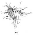
- FIGS. 1-2are perspective views of a tissue retraction assembly forming part of a surgical access system according to the present invention
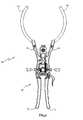
- FIG. 3is a top view of the tissue retraction assembly of FIGS. 1-2 ;
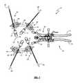
- FIG. 4is a top view of the tissue retraction assembly of FIG. 1 wherein the retractor blade assemblies have been removed;
- FIG. 5is a perspective view of the tissue retraction assembly of FIG. 4 , in which the half-ring assemblies are illustrated in an exploded view removed from the handle assembly;
- FIGS. 6-8are side, perspective, and top views of a retractor blade assembly according to one embodiment of the present invention.
- FIGS. 9-10are front and rear views of a retractor blade according to one embodiment of the present invention.
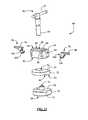
- FIG. 11is a perspective view of a base member of a retractor blade holder assembly of the present invention, with the retractor blade and blade extender removed;
- FIG. 12is an exploded perspective view of the base member of FIG. 11 .
- FIGS. 1-3illustrate a tissue retraction assembly 10 forming part of a surgical access system according to one embodiment of the present invention.
- the tissue retraction assembly 10includes a plurality of retractor blades 12 coupled to a handle assembly 20 via a plurality of blade holder assemblies 42 .
- the tissue retraction assembly 10is shown in a fully retracted or “open” configuration, with the retractor blades 12 positioned a distance from one another so as to form an operative corridor 15 therebetween and extending to a surgical target site (e.g. an annulus of an intervertebral disc). This is accomplished by initially creating a distraction corridor to a surgical target site via any anterior access method well known in the art, such as may be performed via a general or “access” surgeon.
- a surgical target sitee.g. an annulus of an intervertebral disc
- the resulting void or distracted region within the patientis of sufficient size to accommodate tissue retraction assembly 10 as described herein.
- the distal ends of the retractor blades 12are attached to (e.g. introduced into) target vertebrae on either side of an intervertebral space.
- the proximal endsare attached to the blade holder assemblies 42 while the handle assembly 20 is in a first, “closed” position.
- the handle assembly 20may be operated to move the retractor blades 12 into a second, “open” or “retracted” position to create the operative corridor 15 to the surgical target site (e.g. an intervertebral space).
- any or all of the retractor blades 12may be provided with one or more electrodes 39 (preferably at their distal regions, shown more clearly in FIGS. 9-10 ) equipped for use with a nerve surveillance system, such as, by way of example, the type shown and described in the NeuroVision PCT Applications (referenced below).
- the handle assembly 20is substantially similar to the type shown and described in commonly owned and currently pending PCT App. Ser. No. PCT/US2004/031768, entitled “Surgical Access System and Related Methods,” filed on Sep. 27, 2004, and U.S. Provisional Pat. App. Ser. No. 60/617,498, entitled “Surgical Access System and Related Methods,” filed Oct. 8, 2004 (collectively “Maxcess Applications”), the entire contents of which are incorporated by reference into the present application as if disclosed herein.
- the handle assembly 20may be coupled to any number of mechanisms for rigidly registering the handle assembly 20 in fixed relation to the operative site, such as by way of example only an articulating arm mounted to the operating table.
- the handle assembly 20includes first and second arm members 26 , 28 hingedly coupled via coupling mechanism shown generally at 30 .
- the distal ends of first and second arm members 26 , 28may be equipped with arm extensions 40 , 41 (shown more clearly in FIGS. 4-5 ).
- Arm extensions 40 , 41may be formed in any shape desired or required to ensure a suitable operating corridor, including but not limited to a generally curved or arcuate shape.
- Arm extensions 40 , 41may also be configured to couple to the first and second arm members 28 , 26 , respectively, via any number of suitable manners, including but not limited to providing coupling blocks 45 disposed on the proximal ends of the arm extensions 40 , 41 with posts 43 extending therefrom for engagement into corresponding recesses 47 formed within the arm members 26 , 28 .
- This engagement between the posts 43 and recesses 47may be augmented via the use of any number of suitable locking features, including but not limited to passing a set screw (not shown) through an aperture 49 in the arm 26 , 28 such that the set screw (not shown) may be biased into the posts 43 after they have been introduced into the respective recess 47 .
- a plurality of blade holder assemblies 42may be slideably attached to arm extensions 40 .
- Blade holder assemblies 42each include a base member 44 and a blade extender 46 .
- Blade extenders 46are generally elongated in shape and have a medial end dimensioned to slideably engage retractor blades 12 .
- the retractor blades 12are each coupled to a medial end of one of blade extenders 46 .
- at least one retractor blade 12is coupled to the end of the first arm member 26
- at least one retractor blade 12is coupled to the end of the second arm member 28 .
- the arms 26 , 28may be simultaneously opened such that the blades 12 coupled to arm extensions 40 , 41 move away from one another.
- the arm extensions 40 , 41may be opened up before the retractor blades 12 are coupled thereto. That is, the blade extenders 46 may be manually moved in a generally lateral direction (that is, away from the plane of the distal tip of the blade 12 ) in order to create the operative corridor 15 , at which point the blade extender 46 may be coupled to the blade holder assembly 42 to maintain this position. This may be done by moving the blades 12 sequentially or simultaneously (with at least two blades being moved at the same time).
- the dimension and/or shape of the operative corridor 15may be tailored depending upon the degree to which the arms 26 , 28 are opened. That is, the operative corridor 15 may be tailored to provide any number of suitable cross-sectional shapes, including but not limited to a generally circular cross-section, a generally ellipsoidal cross-section, and/or an oval cross-section.
- FIGS. 6-8illustrate in detail the construction of each blade holder assembly 42 and blade 12 according to a preferred embodiment of the present invention.
- Blade holder assembly 42is dimensioned to slideably engage arm extension 40 , and includes a base member 44 and a blade extender 46 .
- base member 44includes a first portion 50 , a second portion 52 , a third portion 54 , pair of clips 56 , 58 , and a pin member 60 .
- the first portion 50may be any geometric shape, including by way of example only generally circular, semi-circular, or generally oval.
- the first portion 50includes a first generally planar surface 66 , a second generally planar surface 68 , art aperture 70 , and a semi-cylindrical cutout region 72 .
- Aperture 66extends through the width of the first portion 50 and is dimensioned to receive shaft 64 of pin 60 .
- Semi-cylindrical cutout region 72is dimensioned to interact with one of arm extensions 40 , 41 .
- the second portion 52may be any geometric shape including by way of example only generally circular, semi-circular, or generally oval, and should have the same general shape as first portion 50 .
- Second portion 52includes a first generally planar surface 74 , a second generally planar surface 76 , an aperture 78 , and a semi-cylindrical cutout region 80 .
- Aperture 78extends through the width of the second portion 52 , is contiguous with aperture 70 , and is dimensioned to receive shaft 64 of pin 60 .
- Semi-cylindrical cutout region 80is dimensioned to interact with one of arm extensions 40 , 41 .
- the third portion 54includes a first generally planar surface 82 , a second surface 84 , a central aperture 86 a pair of first cutout regions 88 , 90 , and a pair of second cutout regions 92 , 94 .
- the third portion 54may be any geometric shape desired, including by way of example only generally circular, semi-circular, generally oval, generally rectangular, or any combination thereof.
- Central aperture 86is generally circular in shape, is contiguous with aperture 78 , and is dimensioned to receive shaft 64 of pin 60 .
- the first pair of cutout regions 88 , 90are located generally on second surface 84 , are generally semi-cylindrical in shape, and are dimensioned to interact with the elongated blade extenders 46 .
- the second pair of cutout regions 92 , 94are generally rectangular in shape, extend substantially the width of third portion 54 , and are dimensioned to receive one of clips 56 , 58 .
- the second pair of cutout regions 92 , 94are positioned generally perpendicularly to first pair of cutout regions 88 , 90 , such that cutout region 92 bisects cutout region 88 , and cutout region 94 bisects cutout region 90 .
- the clips 56 , 58may be any shape necessary to removably secure blade extenders 46 to the base member 42 , and are dimensioned to interact with cutout regions 92 , 94 , respectively.
- Clips 56 , 58include a generally planar surface 96 , 98 , a semi-cylindrical surface 100 , 102 , and an aperture 104 , 106 , respectively.
- the semi-cylindrical surface 100 , 102is dimensioned to interact with the elongated blade extenders 46 , such that the elongated blade extenders 46 are prevented from migrating in a medial or lateral direction.
- Apertures 104 , 106are dimensioned such that they enable clips 56 , 58 to be secured to the third portion 54 .
- the pin 60includes an elongated handle portion 62 and a generally cylindrical shaft 64 .
- the generally cylindrical shaft 64is dimensioned to interact with apertures 70 , 78 , 86 and traverse the combined widths of the first, second, and third portions 50 , 52 , 54 , respectively.
- Pin 60functions to secure the first, second, and third portions 50 , 52 , 54 to each other, and also to secure blade assembly 42 to one of arm extensions 40 , 41 .
- blade extender 46includes a medial portion 108 , a central elongated shaft 110 , and a lateral portion 112 .
- Medial portion 108is dimensioned to interact with elongated slot 126 of retractor blade 12 .
- the medial portion 108also includes a pivot 114 , which may include any mechanism that allows for changes in the angle defined by the elongated blade extender 46 and the retractor blade 12 .
- the pivot 114may comprise a ball-and-socket mechanism.
- the elongated shaft 110is dimensioned to interact with the semi-cylindrical surfaces 88 , 90 of the third portion 54 , and semi-cylindrical surfaces 100 , 102 of the clips 56 , 58 .
- Elongated shaft 110may include ridges 116 to increase friction to serve as an anti-migration enhancing feature.
- FIGS. 9-10illustrate in detail each retractor blade 12 according to a preferred embodiment of the present invention.
- Retractor blade 12includes a proximal end 118 , and distal tip 120 , and an elongated portion 122 therebetween.
- Proximal end 118includes an elongated slot 126 dimensioned to slideably engage the medial portion 108 of the elongated blade extender 46 .
- the elongated portion 122may include a utility clip 124 , which may optionally interact with a light source (not shown) or other mechanism to aid in the procedure.
- Distal tip 120may be generally pointed in nature to enable the distal tip 120 to penetrate a vertebral body in order to secure the retractor blades to the bone.
- the retractor blades 12may be constructed of suitable material and configuration such that light may be transmitted generally distally through the walls of the retractor blades 12 light to shine light at or near the surgical target site. This may be performed by providing the retractor blades 12 having light-transmission characteristics (such as with clear polycarbonate construction) and transmitting the light almost entirely within the walls of the retractor blades 12 (such as by frosting or otherwise rendering opaque portions of the exterior and/or interior) until it exits a portion along the interior (or medially-facing) surface of the retractor blade to shine at or near the surgical target site.
- the exit portionmay be optimally configured such that the light is directed towards the approximate center of the surgical target site and may be provided along the entire inner periphery of the retractor blade 12 or one or more portions therealong.
- a surgeonmay initiate the ALIF procedure by surgical techniques generally known and commonly used in the art.
- This common procedureincludes establishing a small operative corridor by making an incision, clearing the relevant anatomy, and reaching the vertebral body.
- a plurality of retractor bladesmay be inserted such that the distal portions 120 penetrate the targeted vertebral body or bodies in a desired location.
- a handle assembly 20 of the present inventionmay be provided in a “closed” position (preferably rigidly coupled in a fixed relation to the operative site, such as through the use of an articulating arm mounted to the operating table).
- the blade assemblies 42Before coupling the retractor blades 12 to the handle assembly 20 , the blade assemblies 42 should be positioned in the desired locations along arm extensions 40 , 41 .
- the handle assembly 20may be mated to the retractor blades 12 by inserting medial portions 108 of blade extenders 46 into elongated slots 126 .
- the operative corridor 15may be opened by manipulating the handle extenders 31 , 33 to cause the arms 26 , 28 to move away from one another.
- the plurality of retractor blades 12also move away from one another, thus expanding the operative corridor 15 .
- the tissue retraction assembly 10 of the present inventionmay be equipped with one or more electrodes for use in detecting the existence of (and optionally the distance and/or direction to) neural structures associated with the surgical target site or accessing the surgical target site.
- the retractor blades 12may be provided with one or more electrodes 39 (preferably at their distal regions) as shown in FIGS. 9-10 .
- These electrodesare preferably provided for use with a nerve surveillance system such as, by way of example, the type shown and described in the following commonly assigned and co-pending applications: PCT App. Ser. No.
- PCT/US02/22247entitled “System and Methods for Determining Nerve Proximity, Direction, and Pathology During Surgery,” filed on Jul. 11, 2002;
- PCT App. Ser. No. PCT/US02/30617entitled “System and Methods for Performing Surgical Procedures and Assessments,” filed on Sep. 25, 2002;
- PCT App. Ser. No. PCT/US02/35047entitled “System and Methods for Performing Percutaneous Pedicle Integrity Assessments,” filed on Oct. 30, 2002;
- this nerve surveillance systemis capable of detecting the existence of (and optionally the distance and/or direction to) neural structures during the distraction and retraction of tissue by detecting the presence of nerves by applying a stimulation signal to such instruments and monitoring the evoked EMG signals from the myotomes associated with the nerves being passed or approached by the retraction system of the present invention.
- the system as a wholemay be used to form an operative corridor through (or near) any of a variety of tissues having such neural structures, particularly those which, if contacted or impinged, may otherwise result in neural impairment for the patient.
- the access system of the present inventionmay be used to traverse tissue that would ordinarily be deemed unsafe or undesirable, thereby broadening the number of manners in which a given surgical target site may be accessed.
- the surgical access system of the present inventioncan be used in any of a wide variety of surgical or medical applications, above and beyond the spinal applications discussed herein.
- spinal applicationsmay include any procedure wherein instruments, devices, implants and/or compounds are to be introduced into or adjacent the surgical target site, including but not limited to discectomy, fusion (including PLIF, ALIF, TLIF and any fusion effectuated via a lateral or far-lateral approach and involving, by way of example, the introduction of bone products (such as allograft or autograft) and/or devices having ceramic, metal and/or plastic construction (such as mesh) and/or compounds such as bone morphogenic protein), total disc replacement, etc. . . . ).
- bone productssuch as allograft or autograft
- devices having ceramic, metal and/or plastic constructionsuch as mesh
- compoundssuch as bone morphogenic protein
Landscapes
- Health & Medical Sciences (AREA)
- Life Sciences & Earth Sciences (AREA)
- Surgery (AREA)
- Nuclear Medicine, Radiotherapy & Molecular Imaging (AREA)
- Biomedical Technology (AREA)
- Optics & Photonics (AREA)
- Pathology (AREA)
- Radiology & Medical Imaging (AREA)
- Biophysics (AREA)
- Engineering & Computer Science (AREA)
- Physics & Mathematics (AREA)
- Heart & Thoracic Surgery (AREA)
- Medical Informatics (AREA)
- Molecular Biology (AREA)
- Animal Behavior & Ethology (AREA)
- General Health & Medical Sciences (AREA)
- Public Health (AREA)
- Veterinary Medicine (AREA)
- Surgical Instruments (AREA)
Abstract
Description
Claims (24)
Priority Applications (1)
| Application Number | Priority Date | Filing Date | Title |
|---|---|---|---|
| US11/344,711US7785253B1 (en) | 2005-01-31 | 2006-01-31 | Surgical access system and related methods |
Applications Claiming Priority (2)
| Application Number | Priority Date | Filing Date | Title |
|---|---|---|---|
| US64884905P | 2005-01-31 | 2005-01-31 | |
| US11/344,711US7785253B1 (en) | 2005-01-31 | 2006-01-31 | Surgical access system and related methods |
Publications (1)
| Publication Number | Publication Date |
|---|---|
| US7785253B1true US7785253B1 (en) | 2010-08-31 |
Family
ID=42646599
Family Applications (1)
| Application Number | Title | Priority Date | Filing Date |
|---|---|---|---|
| US11/344,711Active2026-03-09US7785253B1 (en) | 2005-01-31 | 2006-01-31 | Surgical access system and related methods |
Country Status (1)
| Country | Link |
|---|---|
| US (1) | US7785253B1 (en) |
Cited By (49)
| Publication number | Priority date | Publication date | Assignee | Title |
|---|---|---|---|---|
| US20080183045A1 (en)* | 2007-01-30 | 2008-07-31 | Mi4Spine, Llc | Retractor Device for Cervical Spinal Fusion |
| US20090125072A1 (en)* | 2007-11-13 | 2009-05-14 | Neubardt Seth L | Surgical bone screw construction |
| US20100094115A1 (en)* | 2005-01-31 | 2010-04-15 | Pond Jr John D | Electrically insulated surgical needle assembly |
| US20150272694A1 (en)* | 2012-06-27 | 2015-10-01 | CamPlex LLC | Surgical visualization system |
| US9265490B2 (en) | 2012-04-16 | 2016-02-23 | DePuy Synthes Products, Inc. | Detachable dilator blade |
| US9278214B2 (en) | 2007-04-30 | 2016-03-08 | Warsaw Orhtopedic, Inc. | Deformity correction using neural integrity monitoring |
| US9492065B2 (en) | 2012-06-27 | 2016-11-15 | Camplex, Inc. | Surgical retractor with video cameras |
| US20170014118A1 (en)* | 2015-07-15 | 2017-01-19 | Warsaw Orthopedic, Inc. | Surgical instrument and method of use |
| US9693762B2 (en)* | 2014-03-03 | 2017-07-04 | Alphatec Spine, Inc. | Soft tissue retractor |
| US20170231614A1 (en) | 2014-09-10 | 2017-08-17 | Spinal Elements, Inc. | Retractor |
| US9757067B1 (en)* | 2012-11-09 | 2017-09-12 | Nuvasive, Inc. | Systems and methods for performing neurophysiologic monitoring during spine surgery |
| US9782159B2 (en) | 2013-03-13 | 2017-10-10 | Camplex, Inc. | Surgical visualization systems |
| US9949651B2 (en) | 2011-11-01 | 2018-04-24 | DePuy Synthes Products, Inc. | Intraoperative neurophysiological monitoring system |
| US10028651B2 (en) | 2013-09-20 | 2018-07-24 | Camplex, Inc. | Surgical visualization systems and displays |
| US10172603B2 (en)* | 2013-03-11 | 2019-01-08 | Spinal Elements, Inc. | Method of using a surgical tissue retractor |
| US10194896B2 (en) | 2014-11-03 | 2019-02-05 | Archer Medical, Inc. | Surgical retractor system and method |
| US10219798B2 (en) | 2015-07-15 | 2019-03-05 | Warsaw Orthopedic, Inc. | Surgical instrument and method of use |
| US10278686B2 (en) | 2010-09-20 | 2019-05-07 | DePuy Synthes Products, Inc. | Spinal access retractor |
| US10321833B2 (en) | 2016-10-05 | 2019-06-18 | Innovative Surgical Solutions. | Neural locating method |
| US10376208B2 (en) | 2013-09-20 | 2019-08-13 | Innovative Surgical Solutions, Llc | Nerve mapping system |
| US10376209B2 (en) | 2013-09-20 | 2019-08-13 | Innovative Surgical Solutions, Llc | Neural locating method |
| US10449002B2 (en) | 2013-09-20 | 2019-10-22 | Innovative Surgical Solutions, Llc | Method of mapping a nerve |
| US10478097B2 (en) | 2013-08-13 | 2019-11-19 | Innovative Surgical Solutions | Neural event detection |
| US10478096B2 (en) | 2013-08-13 | 2019-11-19 | Innovative Surgical Solutions. | Neural event detection |
| US10568499B2 (en) | 2013-09-20 | 2020-02-25 | Camplex, Inc. | Surgical visualization systems and displays |
| US10687797B2 (en) | 2008-12-18 | 2020-06-23 | Howmedica Osteonics Corp. | Lateral access system for the lumbar spine |
| US10702353B2 (en) | 2014-12-05 | 2020-07-07 | Camplex, Inc. | Surgical visualizations systems and displays |
| US10799226B2 (en) | 2015-07-15 | 2020-10-13 | Warsaw Orthopedic, Inc. | Surgical adaptor and method |
| US10870002B2 (en) | 2018-10-12 | 2020-12-22 | DePuy Synthes Products, Inc. | Neuromuscular sensing device with multi-sensor array |
| US10869616B2 (en) | 2018-06-01 | 2020-12-22 | DePuy Synthes Products, Inc. | Neural event detection |
| US10918455B2 (en) | 2017-05-08 | 2021-02-16 | Camplex, Inc. | Variable light source |
| US10966798B2 (en) | 2015-11-25 | 2021-04-06 | Camplex, Inc. | Surgical visualization systems and displays |
| US10973505B2 (en) | 2016-03-09 | 2021-04-13 | Spinal Elements, Inc. | Retractor |
| US11154378B2 (en) | 2015-03-25 | 2021-10-26 | Camplex, Inc. | Surgical visualization systems and displays |
| US11166709B2 (en) | 2016-08-23 | 2021-11-09 | Stryker European Operations Holdings Llc | Instrumentation and methods for the implantation of spinal implants |
| US11191532B2 (en)* | 2018-03-30 | 2021-12-07 | Stryker European Operations Holdings Llc | Lateral access retractor and core insertion |
| US11266391B2 (en) | 2019-02-11 | 2022-03-08 | Warsaw Orthopedic, Inc. | Surgical retractor and method |
| USD956224S1 (en) | 2020-05-12 | 2022-06-28 | Innovasis, Inc. | Surgical retractor |
| USD956225S1 (en) | 2020-05-12 | 2022-06-28 | Innovasis, Inc. | Surgical retractor |
| USD956223S1 (en) | 2020-05-12 | 2022-06-28 | Innovasis, Inc. | Surgical retractor |
| US11389151B2 (en)* | 2019-11-22 | 2022-07-19 | Institute for Musculoskeletal Science and Education, Ltd. | Modular retractor system |
| US11399777B2 (en) | 2019-09-27 | 2022-08-02 | DePuy Synthes Products, Inc. | Intraoperative neural monitoring system and method |
| US11413029B2 (en) | 2018-10-24 | 2022-08-16 | Stryker European Operations Holdings Llc | Anterior to psoas instrumentation |
| US11432810B2 (en) | 2020-05-12 | 2022-09-06 | Innovasis, Inc. | Systems and methods for surgical retraction |
| US11464504B2 (en) | 2017-08-17 | 2022-10-11 | Stryker European Operations Holdings Llc | Lateral access bridges, shims and lighting including rod lighting |
| US11564674B2 (en) | 2019-11-27 | 2023-01-31 | K2M, Inc. | Lateral access system and method of use |
| US11660082B2 (en) | 2011-11-01 | 2023-05-30 | DePuy Synthes Products, Inc. | Dilation system |
| US11701098B2 (en) | 2019-02-11 | 2023-07-18 | Warsaw Orthopedic, Inc. | Surgical retractor system and method |
| US11737743B2 (en) | 2007-10-05 | 2023-08-29 | DePuy Synthes Products, Inc. | Dilation system and method of using the same |
Citations (130)
| Publication number | Priority date | Publication date | Assignee | Title |
|---|---|---|---|---|
| US1548184A (en) | 1923-04-11 | 1925-08-04 | Will J Cameron | Holder and control for pulp testers |
| US2704064A (en) | 1952-09-10 | 1955-03-15 | Meditron Company | Neurosurgical stimulator |
| US2736002A (en) | 1956-02-21 | oriel | ||
| US2808826A (en) | 1956-01-19 | 1957-10-08 | Teca Corp | Electro-diagnostic apparatus and a circuit therefor |
| US3364929A (en) | 1964-12-21 | 1968-01-23 | Burroughs Wellcome Co | Method for administering muscle relaxant drug |
| US3664329A (en) | 1970-03-09 | 1972-05-23 | Concept | Nerve locator/stimulator |
| US3682162A (en) | 1968-12-13 | 1972-08-08 | Wellcome Found | Combined electrode and hypodermic syringe needle |
| US3785368A (en) | 1971-08-23 | 1974-01-15 | Carthy T Mc | Abnormal nerve pressure locus detector and method |
| US3830226A (en) | 1973-06-15 | 1974-08-20 | Concept | Variable output nerve locator |
| US3957036A (en) | 1975-02-03 | 1976-05-18 | Baylor College Of Medicine | Method and apparatus for recording activity in intact nerves |
| US4099519A (en) | 1977-01-14 | 1978-07-11 | Warren Fred E | Diagnostic device |
| US4164214A (en) | 1977-07-25 | 1979-08-14 | The Regents Of The University Of California | Method and apparatus for measuring the sensitivity of teeth |
| US4207897A (en) | 1976-07-21 | 1980-06-17 | Spembly Limited | Cryosurgical probe |
| US4224949A (en) | 1977-11-17 | 1980-09-30 | Cornell Research Foundation, Inc. | Method and electrical resistance probe for detection of estrus in bovine |
| US4235242A (en) | 1979-04-02 | 1980-11-25 | Med General, Inc. | Electronic circuit permitting simultaneous use of stimulating and monitoring equipment |
| US4285347A (en) | 1979-07-25 | 1981-08-25 | Cordis Corporation | Stabilized directional neural electrode lead |
| US4291705A (en) | 1979-09-10 | 1981-09-29 | The Regents Of The University Of California | Neuromuscular block monitor |
| US4461300A (en) | 1982-01-18 | 1984-07-24 | Sutter Biomedical, Inc. | Bone and tissue healing device including a special electrode assembly and method |
| US4515168A (en) | 1983-07-22 | 1985-05-07 | Chester Martin H | Clamp-on nerve stimulator and locator |
| US4519403A (en) | 1983-04-29 | 1985-05-28 | Medtronic, Inc. | Balloon lead and inflator |
| US4545374A (en) | 1982-09-03 | 1985-10-08 | Jacobson Robert E | Method and instruments for performing a percutaneous lumbar diskectomy |
| US4561445A (en) | 1983-05-25 | 1985-12-31 | Joseph J. Berke | Elongated needle electrode and method of making same |
| US4562832A (en) | 1984-01-21 | 1986-01-07 | Wilder Joseph R | Medical instrument and light pipe illumination assembly |
| US4573448A (en) | 1983-10-05 | 1986-03-04 | Pilling Co. | Method for decompressing herniated intervertebral discs |
| US4592369A (en) | 1982-07-12 | 1986-06-03 | National Research Development Corp. | Method and apparatus for use in temporal analysis of waveforms |
| US4595018A (en) | 1983-06-10 | 1986-06-17 | Instrumentarium Corp. | Method of further developing the measuring of a neuro-muscular junction |
| US4633889A (en) | 1984-12-12 | 1987-01-06 | Andrew Talalla | Stimulation of cauda-equina spinal nerves |
| US4658835A (en) | 1985-07-25 | 1987-04-21 | Cordis Corporation | Neural stimulating lead with fixation canopy formation |
| US4744371A (en) | 1987-04-27 | 1988-05-17 | Cordis Leads, Inc. | Multi-conductor lead assembly for temporary use |
| US4759377A (en) | 1986-11-26 | 1988-07-26 | Regents Of The University Of Minnesota | Apparatus and method for mechanical stimulation of nerves |
| US4807642A (en) | 1985-08-16 | 1989-02-28 | Brown David A | Electromyographic repetitive strain injury monitor |
| US4892105A (en) | 1986-03-28 | 1990-01-09 | The Cleveland Clinic Foundation | Electrical stimulus probe |
| US4926865A (en) | 1987-10-01 | 1990-05-22 | Oman Paul S | Microcomputer-based nerve and muscle stimulator |
| US4949707A (en)* | 1984-11-08 | 1990-08-21 | Minnesota Scientific, Inc. | Retractor apparatus |
| US4962766A (en) | 1989-07-19 | 1990-10-16 | Herzon Garrett D | Nerve locator and stimulator |
| US4964411A (en) | 1989-07-13 | 1990-10-23 | Empi, Inc. | Evoked EMG signal processing |
| US5007902A (en) | 1988-03-09 | 1991-04-16 | B. Braun Melsungen Ag | Catheter set for plexus anesthesia |
| US5058602A (en) | 1988-09-30 | 1991-10-22 | Brody Stanley R | Paraspinal electromyography scanning |
| US5081990A (en) | 1990-05-11 | 1992-01-21 | New York University | Catheter for spinal epidural injection of drugs and measurement of evoked potentials |
| US5092344A (en) | 1990-11-19 | 1992-03-03 | Lee Tzium Shou | Remote indicator for stimulator |
| US5127403A (en) | 1988-07-05 | 1992-07-07 | Cardiac Control Systems, Inc. | Pacemaker catheter utilizing bipolar electrodes spaced in accordance to the length of a heart depolarization signal |
| US5161533A (en) | 1991-09-19 | 1992-11-10 | Xomed-Treace Inc. | Break-apart needle electrode system for monitoring facial EMG |
| US5196015A (en) | 1992-04-30 | 1993-03-23 | Neubardt Seth L | Procedure for spinal pedicle screw insertion |
| USRE34390E (en) | 1980-12-31 | 1993-09-28 | Nicolet Instrument Corporation | Apparatus and method for topographic display of multichannel EEG data |
| US5255691A (en) | 1991-11-13 | 1993-10-26 | Medtronic, Inc. | Percutaneous epidural lead introducing system and method |
| US5282468A (en) | 1990-06-07 | 1994-02-01 | Medtronic, Inc. | Implantable neural electrode |
| US5284153A (en) | 1992-04-14 | 1994-02-08 | Brigham And Women's Hospital | Method for locating a nerve and for protecting nerves from injury during surgery |
| US5299563A (en) | 1992-07-31 | 1994-04-05 | Seton Joseph Z | Method of using a surgical retractor |
| US5312417A (en) | 1992-07-29 | 1994-05-17 | Wilk Peter J | Laparoscopic cannula assembly and associated method |
| US5313956A (en) | 1990-12-04 | 1994-05-24 | Dorsograf Ab | Apparatus for measuring the transport time of nerve signals |
| US5327902A (en) | 1993-05-14 | 1994-07-12 | Lemmen Roger D | Apparatus for use in nerve conduction studies |
| US5333618A (en) | 1993-06-30 | 1994-08-02 | Gregory Lekhtman | Portable self-contained instrument for the measurement of nerve resistance of a patient |
| US5375067A (en) | 1992-12-11 | 1994-12-20 | Nicolet Instrument Corporation | Method and apparatus for adjustment of acquisition parameters in a data acquisition system such as a digital oscilloscope |
| US5383876A (en) | 1992-11-13 | 1995-01-24 | American Cardiac Ablation Co., Inc. | Fluid cooled electrosurgical probe for cutting and cauterizing tissue |
| US5474558A (en) | 1992-04-30 | 1995-12-12 | Neubardt; Seth L. | Procedure and system for spinal pedicle screw insertion |
| US5480440A (en) | 1991-08-15 | 1996-01-02 | Smith & Nephew Richards, Inc. | Open surgical technique for vertebral fixation with subcutaneous fixators positioned between the skin and the lumbar fascia of a patient |
| US5482038A (en) | 1994-06-28 | 1996-01-09 | Cadwell Industries, Inc. | Needle electrode assembly |
| US5484437A (en) | 1988-06-13 | 1996-01-16 | Michelson; Gary K. | Apparatus and method of inserting spinal implants |
| US5540235A (en) | 1994-06-30 | 1996-07-30 | Wilson; John R. | Adaptor for neurophysiological monitoring with a personal computer |
| US5549656A (en) | 1993-08-16 | 1996-08-27 | Med Serve Group, Inc. | Combination neuromuscular stimulator and electromyograph system |
| US5560372A (en) | 1994-02-02 | 1996-10-01 | Cory; Philip C. | Non-invasive, peripheral nerve mapping device and method of use |
| US5566678A (en) | 1993-09-10 | 1996-10-22 | Cadwell Industries, Inc. | Digital EEG noise synthesizer |
| US5579781A (en) | 1994-10-13 | 1996-12-03 | Cooke; Thomas H. | Wireless transmitter for needle electrodes as used in electromyography |
| US5593429A (en) | 1994-06-28 | 1997-01-14 | Cadwell Industries, Inc. | Needle electrode with depth of penetration limiter |
| US5599279A (en) | 1994-03-16 | 1997-02-04 | Gus J. Slotman | Surgical instruments and method useful for endoscopic spinal procedures |
| US5630813A (en) | 1994-12-08 | 1997-05-20 | Kieturakis; Maciej J. | Electro-cauterizing dissector and method for facilitating breast implant procedure |
| US5671752A (en) | 1995-03-31 | 1997-09-30 | Universite De Montreal/The Royal Insitution For The Advancement Of Learning (Mcgill University) | Diaphragm electromyography analysis method and system |
| US5707359A (en) | 1995-11-14 | 1998-01-13 | Bufalini; Bruno | Expanding trocar assembly |
| US5711307A (en) | 1995-04-13 | 1998-01-27 | Liberty Mutual Insurance Company | Method and apparatus for detecting myoelectric activity from the surface of the skin |
| US5728046A (en) | 1995-06-23 | 1998-03-17 | Aesculap Ag | Surgical retractor |
| US5741253A (en) | 1988-06-13 | 1998-04-21 | Michelson; Gary Karlin | Method for inserting spinal implants |
| US5759159A (en) | 1996-09-25 | 1998-06-02 | Ormco Corporation | Method and apparatus for apical detection with complex impedance measurement |
| US5772661A (en) | 1988-06-13 | 1998-06-30 | Michelson; Gary Karlin | Methods and instrumentation for the surgical correction of human thoracic and lumbar spinal disease from the antero-lateral aspect of the spine |
| US5775331A (en) | 1995-06-07 | 1998-07-07 | Uromed Corporation | Apparatus and method for locating a nerve |
| US5779642A (en) | 1996-01-16 | 1998-07-14 | Nightengale; Christopher | Interrogation device and method |
| US5785658A (en) | 1992-09-14 | 1998-07-28 | Sexant Medical Corporation | In vivo tissue analysis methods and apparatus |
| US5797854A (en) | 1995-08-01 | 1998-08-25 | Hedgecock; James L. | Method and apparatus for testing and measuring current perception threshold and motor nerve junction performance |
| US5814073A (en) | 1996-12-13 | 1998-09-29 | Bonutti; Peter M. | Method and apparatus for positioning a suture anchor |
| US5830151A (en) | 1995-04-10 | 1998-11-03 | Innovative Design Associates | Apparatus for locating and anesthetizing peripheral nerves a method therefor |
| US5851191A (en) | 1997-07-01 | 1998-12-22 | Neurometrix, Inc. | Apparatus and methods for assessment of neuromuscular function |
| US5853373A (en) | 1996-08-05 | 1998-12-29 | Becton, Dickinson And Company | Bi-level charge pulse apparatus to facilitate nerve location during peripheral nerve block procedures |
| US5862314A (en) | 1996-11-01 | 1999-01-19 | Micron Electronics, Inc. | System and method for remapping defective memory locations |
| US5860973A (en) | 1995-02-27 | 1999-01-19 | Michelson; Gary Karlin | Translateral spinal implant |
| US5872314A (en) | 1997-07-25 | 1999-02-16 | Clinton; Robert P. | Method and apparatus for measuring characteristics of meat |
| US5888196A (en) | 1990-03-02 | 1999-03-30 | General Surgical Innovations, Inc. | Mechanically expandable arthroscopic retractors |
| US5902231A (en) | 1996-03-22 | 1999-05-11 | Sdgi Holdings, Inc. | Devices and methods for percutaneous surgery |
| US5928158A (en) | 1997-03-25 | 1999-07-27 | Aristides; Arellano | Medical instrument with nerve sensor |
| US5928139A (en) | 1998-04-24 | 1999-07-27 | Koros; Tibor B. | Retractor with adjustable length blades and light pipe guides |
| US6004262A (en) | 1998-05-04 | 1999-12-21 | Ad-Tech Medical Instrument Corp. | Visually-positioned electrical monitoring apparatus |
| EP0972538A2 (en) | 1998-07-13 | 2000-01-19 | Medtronic, Inc. | System for providing medical electrical stimulation to a portion of the nervous system |
| US6024697A (en)* | 1999-01-11 | 2000-02-15 | Pisarik; Paul | Multi-bladed speculum for dilating a body cavity |
| US6027456A (en) | 1998-07-10 | 2000-02-22 | Advanced Neuromodulation Systems, Inc. | Apparatus and method for positioning spinal cord stimulation leads |
| US6038477A (en) | 1998-12-23 | 2000-03-14 | Axon Engineering, Inc. | Multiple channel nerve stimulator with channel isolation |
| US6050992A (en) | 1997-05-19 | 2000-04-18 | Radiotherapeutics Corporation | Apparatus and method for treating tissue with multiple electrodes |
| US6074343A (en) | 1999-04-16 | 2000-06-13 | Nathanson; Michael | Surgical tissue retractor |
| US6083154A (en)* | 1997-10-23 | 2000-07-04 | Sofamor S.N.C. | Surgical instrumentation and method for retracting and shifting tissues |
| US6104957A (en) | 1998-08-21 | 2000-08-15 | Alo; Kenneth M. | Epidural nerve root stimulation with lead placement method |
| US6120503A (en) | 1994-03-28 | 2000-09-19 | Michelson; Gary Karlin | Apparatus instrumentation, and method for spinal fixation |
| US6132386A (en) | 1997-07-01 | 2000-10-17 | Neurometrix, Inc. | Methods for the assessment of neuromuscular function by F-wave latency |
| US6132387A (en) | 1997-07-01 | 2000-10-17 | Neurometrix, Inc. | Neuromuscular electrode |
| US6135965A (en) | 1996-12-02 | 2000-10-24 | Board Of Regents, The University Of Texas System | Spectroscopic detection of cervical pre-cancer using radial basis function networks |
| US6146335A (en) | 1997-07-01 | 2000-11-14 | Neurometrix, Inc. | Apparatus for methods for the assessment of neuromuscular function of the lower extremity |
| US6161047A (en) | 1998-04-30 | 2000-12-12 | Medtronic Inc. | Apparatus and method for expanding a stimulation lead body in situ |
| US6206826B1 (en) | 1997-12-18 | 2001-03-27 | Sdgi Holdings, Inc. | Devices and methods for percutaneous surgery |
| US6224549B1 (en) | 1999-04-20 | 2001-05-01 | Nicolet Biomedical, Inc. | Medical signal monitoring and display |
| US6259945B1 (en) | 1999-04-30 | 2001-07-10 | Uromed Corporation | Method and device for locating a nerve |
| US6266558B1 (en) | 1998-12-01 | 2001-07-24 | Neurometrix, Inc. | Apparatus and method for nerve conduction measurements with automatic setting of stimulus intensity |
| US6292701B1 (en) | 1998-08-12 | 2001-09-18 | Medtronic Xomed, Inc. | Bipolar electrical stimulus probe with planar electrodes |
| US6306100B1 (en) | 1997-12-16 | 2001-10-23 | Richard L. Prass | Intraoperative neurophysiological monitoring system |
| US6312392B1 (en) | 2000-04-06 | 2001-11-06 | Garrett D. Herzon | Bipolar handheld nerve locator and evaluator |
| US6334068B1 (en) | 1999-09-14 | 2001-12-25 | Medtronic Xomed, Inc. | Intraoperative neuroelectrophysiological monitor |
| US20020007129A1 (en) | 2000-06-08 | 2002-01-17 | Marino James F. | Nerve movement and status detection system and method |
| US20020072686A1 (en) | 2000-05-18 | 2002-06-13 | Nuvasive, Inc. | Tissue discrimination and applications in medical procedures |
| US6425901B1 (en) | 1995-12-07 | 2002-07-30 | Loma Linda University Medical Center | Vascular wound closure system |
| US6466817B1 (en) | 1999-11-24 | 2002-10-15 | Nuvasive, Inc. | Nerve proximity and status detection system and method |
| US20020161415A1 (en) | 2001-04-26 | 2002-10-31 | Ehud Cohen | Actuation and control of limbs through motor nerve stimulation |
| US20020177753A1 (en)* | 2001-05-25 | 2002-11-28 | Minnesota Scientific, Inc. | Multi-position spherical retractor holder |
| US6564078B1 (en) | 1998-12-23 | 2003-05-13 | Nuvasive, Inc. | Nerve surveillance cannula systems |
| US20050004593A1 (en) | 2001-10-30 | 2005-01-06 | Depuy Spine, Inc. | Non cannulated dilators |
| US20050004623A1 (en) | 2002-10-30 | 2005-01-06 | Patrick Miles | System and methods for performing percutaneous pedicle integrity assessments |
| US6869398B2 (en)* | 2003-01-06 | 2005-03-22 | Theodore G. Obenchain | Four-blade surgical speculum |
| US20050075578A1 (en) | 2001-09-25 | 2005-04-07 | James Gharib | System and methods for performing surgical procedures and assessments |
| US6902569B2 (en) | 2000-08-17 | 2005-06-07 | Image-Guided Neurologics, Inc. | Trajectory guide with instrument immobilizer |
| US20050149035A1 (en) | 2003-10-17 | 2005-07-07 | Nuvasive, Inc. | Surgical access system and related methods |
| WO2005013805A3 (en) | 2003-08-05 | 2005-07-28 | Nuvasive Inc | Systemand methods for performing dynamic pedicle integrity assessments |
| US6929606B2 (en) | 2001-01-29 | 2005-08-16 | Depuy Spine, Inc. | Retractor and method for spinal pedicle screw placement |
| US20050182454A1 (en) | 2001-07-11 | 2005-08-18 | Nuvasive, Inc. | System and methods for determining nerve proximity, direction, and pathology during surgery |
| US20060069315A1 (en) | 2003-09-25 | 2006-03-30 | Patrick Miles | Surgical access system and related methods |
| WO2006042241A2 (en) | 2004-10-08 | 2006-04-20 | Nuvasive, Inc. | Surgical access system and related methods |
| US7079883B2 (en) | 1998-12-23 | 2006-07-18 | Nuvaslve, Inc. | Nerve surveillance cannulae systems |
- 2006
- 2006-01-31USUS11/344,711patent/US7785253B1/enactiveActive
Patent Citations (140)
| Publication number | Priority date | Publication date | Assignee | Title |
|---|---|---|---|---|
| US2736002A (en) | 1956-02-21 | oriel | ||
| US1548184A (en) | 1923-04-11 | 1925-08-04 | Will J Cameron | Holder and control for pulp testers |
| US2704064A (en) | 1952-09-10 | 1955-03-15 | Meditron Company | Neurosurgical stimulator |
| US2808826A (en) | 1956-01-19 | 1957-10-08 | Teca Corp | Electro-diagnostic apparatus and a circuit therefor |
| US3364929A (en) | 1964-12-21 | 1968-01-23 | Burroughs Wellcome Co | Method for administering muscle relaxant drug |
| US3682162A (en) | 1968-12-13 | 1972-08-08 | Wellcome Found | Combined electrode and hypodermic syringe needle |
| US3664329A (en) | 1970-03-09 | 1972-05-23 | Concept | Nerve locator/stimulator |
| US3785368A (en) | 1971-08-23 | 1974-01-15 | Carthy T Mc | Abnormal nerve pressure locus detector and method |
| US3830226A (en) | 1973-06-15 | 1974-08-20 | Concept | Variable output nerve locator |
| US3957036A (en) | 1975-02-03 | 1976-05-18 | Baylor College Of Medicine | Method and apparatus for recording activity in intact nerves |
| US4207897A (en) | 1976-07-21 | 1980-06-17 | Spembly Limited | Cryosurgical probe |
| US4099519A (en) | 1977-01-14 | 1978-07-11 | Warren Fred E | Diagnostic device |
| US4164214A (en) | 1977-07-25 | 1979-08-14 | The Regents Of The University Of California | Method and apparatus for measuring the sensitivity of teeth |
| US4224949A (en) | 1977-11-17 | 1980-09-30 | Cornell Research Foundation, Inc. | Method and electrical resistance probe for detection of estrus in bovine |
| US4235242A (en) | 1979-04-02 | 1980-11-25 | Med General, Inc. | Electronic circuit permitting simultaneous use of stimulating and monitoring equipment |
| US4285347A (en) | 1979-07-25 | 1981-08-25 | Cordis Corporation | Stabilized directional neural electrode lead |
| US4291705A (en) | 1979-09-10 | 1981-09-29 | The Regents Of The University Of California | Neuromuscular block monitor |
| USRE34390E (en) | 1980-12-31 | 1993-09-28 | Nicolet Instrument Corporation | Apparatus and method for topographic display of multichannel EEG data |
| US4461300A (en) | 1982-01-18 | 1984-07-24 | Sutter Biomedical, Inc. | Bone and tissue healing device including a special electrode assembly and method |
| US4592369A (en) | 1982-07-12 | 1986-06-03 | National Research Development Corp. | Method and apparatus for use in temporal analysis of waveforms |
| US4545374A (en) | 1982-09-03 | 1985-10-08 | Jacobson Robert E | Method and instruments for performing a percutaneous lumbar diskectomy |
| US4519403A (en) | 1983-04-29 | 1985-05-28 | Medtronic, Inc. | Balloon lead and inflator |
| US4561445A (en) | 1983-05-25 | 1985-12-31 | Joseph J. Berke | Elongated needle electrode and method of making same |
| US4595018A (en) | 1983-06-10 | 1986-06-17 | Instrumentarium Corp. | Method of further developing the measuring of a neuro-muscular junction |
| US4515168A (en) | 1983-07-22 | 1985-05-07 | Chester Martin H | Clamp-on nerve stimulator and locator |
| US4573448A (en) | 1983-10-05 | 1986-03-04 | Pilling Co. | Method for decompressing herniated intervertebral discs |
| US4562832A (en) | 1984-01-21 | 1986-01-07 | Wilder Joseph R | Medical instrument and light pipe illumination assembly |
| US4949707A (en)* | 1984-11-08 | 1990-08-21 | Minnesota Scientific, Inc. | Retractor apparatus |
| US4633889A (en) | 1984-12-12 | 1987-01-06 | Andrew Talalla | Stimulation of cauda-equina spinal nerves |
| US4658835A (en) | 1985-07-25 | 1987-04-21 | Cordis Corporation | Neural stimulating lead with fixation canopy formation |
| US4807642A (en) | 1985-08-16 | 1989-02-28 | Brown David A | Electromyographic repetitive strain injury monitor |
| US4892105A (en) | 1986-03-28 | 1990-01-09 | The Cleveland Clinic Foundation | Electrical stimulus probe |
| US4759377A (en) | 1986-11-26 | 1988-07-26 | Regents Of The University Of Minnesota | Apparatus and method for mechanical stimulation of nerves |
| US4744371A (en) | 1987-04-27 | 1988-05-17 | Cordis Leads, Inc. | Multi-conductor lead assembly for temporary use |
| US4926865A (en) | 1987-10-01 | 1990-05-22 | Oman Paul S | Microcomputer-based nerve and muscle stimulator |
| US5007902A (en) | 1988-03-09 | 1991-04-16 | B. Braun Melsungen Ag | Catheter set for plexus anesthesia |
| US5741253A (en) | 1988-06-13 | 1998-04-21 | Michelson; Gary Karlin | Method for inserting spinal implants |
| US5484437A (en) | 1988-06-13 | 1996-01-16 | Michelson; Gary K. | Apparatus and method of inserting spinal implants |
| US5772661A (en) | 1988-06-13 | 1998-06-30 | Michelson; Gary Karlin | Methods and instrumentation for the surgical correction of human thoracic and lumbar spinal disease from the antero-lateral aspect of the spine |
| US5127403A (en) | 1988-07-05 | 1992-07-07 | Cardiac Control Systems, Inc. | Pacemaker catheter utilizing bipolar electrodes spaced in accordance to the length of a heart depolarization signal |
| US5058602A (en) | 1988-09-30 | 1991-10-22 | Brody Stanley R | Paraspinal electromyography scanning |
| US4964411A (en) | 1989-07-13 | 1990-10-23 | Empi, Inc. | Evoked EMG signal processing |
| US4962766A (en) | 1989-07-19 | 1990-10-16 | Herzon Garrett D | Nerve locator and stimulator |
| US5888196A (en) | 1990-03-02 | 1999-03-30 | General Surgical Innovations, Inc. | Mechanically expandable arthroscopic retractors |
| US5081990A (en) | 1990-05-11 | 1992-01-21 | New York University | Catheter for spinal epidural injection of drugs and measurement of evoked potentials |
| US5282468A (en) | 1990-06-07 | 1994-02-01 | Medtronic, Inc. | Implantable neural electrode |
| US5092344A (en) | 1990-11-19 | 1992-03-03 | Lee Tzium Shou | Remote indicator for stimulator |
| US5313956A (en) | 1990-12-04 | 1994-05-24 | Dorsograf Ab | Apparatus for measuring the transport time of nerve signals |
| US5480440A (en) | 1991-08-15 | 1996-01-02 | Smith & Nephew Richards, Inc. | Open surgical technique for vertebral fixation with subcutaneous fixators positioned between the skin and the lumbar fascia of a patient |
| US5161533A (en) | 1991-09-19 | 1992-11-10 | Xomed-Treace Inc. | Break-apart needle electrode system for monitoring facial EMG |
| US5255691A (en) | 1991-11-13 | 1993-10-26 | Medtronic, Inc. | Percutaneous epidural lead introducing system and method |
| US5284153A (en) | 1992-04-14 | 1994-02-08 | Brigham And Women's Hospital | Method for locating a nerve and for protecting nerves from injury during surgery |
| US5284154A (en) | 1992-04-14 | 1994-02-08 | Brigham And Women's Hospital | Apparatus for locating a nerve and for protecting nerves from injury during surgery |
| US5196015A (en) | 1992-04-30 | 1993-03-23 | Neubardt Seth L | Procedure for spinal pedicle screw insertion |
| US5474558A (en) | 1992-04-30 | 1995-12-12 | Neubardt; Seth L. | Procedure and system for spinal pedicle screw insertion |
| US5312417A (en) | 1992-07-29 | 1994-05-17 | Wilk Peter J | Laparoscopic cannula assembly and associated method |
| US5299563A (en) | 1992-07-31 | 1994-04-05 | Seton Joseph Z | Method of using a surgical retractor |
| US5785658A (en) | 1992-09-14 | 1998-07-28 | Sexant Medical Corporation | In vivo tissue analysis methods and apparatus |
| US5383876A (en) | 1992-11-13 | 1995-01-24 | American Cardiac Ablation Co., Inc. | Fluid cooled electrosurgical probe for cutting and cauterizing tissue |
| US5375067A (en) | 1992-12-11 | 1994-12-20 | Nicolet Instrument Corporation | Method and apparatus for adjustment of acquisition parameters in a data acquisition system such as a digital oscilloscope |
| US5327902A (en) | 1993-05-14 | 1994-07-12 | Lemmen Roger D | Apparatus for use in nerve conduction studies |
| US5333618A (en) | 1993-06-30 | 1994-08-02 | Gregory Lekhtman | Portable self-contained instrument for the measurement of nerve resistance of a patient |
| US5549656A (en) | 1993-08-16 | 1996-08-27 | Med Serve Group, Inc. | Combination neuromuscular stimulator and electromyograph system |
| US5566678A (en) | 1993-09-10 | 1996-10-22 | Cadwell Industries, Inc. | Digital EEG noise synthesizer |
| US5566678B1 (en) | 1993-09-10 | 1999-11-30 | Cadwell Ind Inc | Digital eeg noise synthesizer |
| US5560372A (en) | 1994-02-02 | 1996-10-01 | Cory; Philip C. | Non-invasive, peripheral nerve mapping device and method of use |
| US5599279A (en) | 1994-03-16 | 1997-02-04 | Gus J. Slotman | Surgical instruments and method useful for endoscopic spinal procedures |
| US6120503A (en) | 1994-03-28 | 2000-09-19 | Michelson; Gary Karlin | Apparatus instrumentation, and method for spinal fixation |
| US5593429A (en) | 1994-06-28 | 1997-01-14 | Cadwell Industries, Inc. | Needle electrode with depth of penetration limiter |
| US5482038A (en) | 1994-06-28 | 1996-01-09 | Cadwell Industries, Inc. | Needle electrode assembly |
| US5540235A (en) | 1994-06-30 | 1996-07-30 | Wilson; John R. | Adaptor for neurophysiological monitoring with a personal computer |
| US5579781A (en) | 1994-10-13 | 1996-12-03 | Cooke; Thomas H. | Wireless transmitter for needle electrodes as used in electromyography |
| US5630813A (en) | 1994-12-08 | 1997-05-20 | Kieturakis; Maciej J. | Electro-cauterizing dissector and method for facilitating breast implant procedure |
| US5860973A (en) | 1995-02-27 | 1999-01-19 | Michelson; Gary Karlin | Translateral spinal implant |
| US5671752A (en) | 1995-03-31 | 1997-09-30 | Universite De Montreal/The Royal Insitution For The Advancement Of Learning (Mcgill University) | Diaphragm electromyography analysis method and system |
| US5830151A (en) | 1995-04-10 | 1998-11-03 | Innovative Design Associates | Apparatus for locating and anesthetizing peripheral nerves a method therefor |
| US5711307A (en) | 1995-04-13 | 1998-01-27 | Liberty Mutual Insurance Company | Method and apparatus for detecting myoelectric activity from the surface of the skin |
| US5775331A (en) | 1995-06-07 | 1998-07-07 | Uromed Corporation | Apparatus and method for locating a nerve |
| US5728046A (en) | 1995-06-23 | 1998-03-17 | Aesculap Ag | Surgical retractor |
| US5797854A (en) | 1995-08-01 | 1998-08-25 | Hedgecock; James L. | Method and apparatus for testing and measuring current perception threshold and motor nerve junction performance |
| US5707359A (en) | 1995-11-14 | 1998-01-13 | Bufalini; Bruno | Expanding trocar assembly |
| US6425901B1 (en) | 1995-12-07 | 2002-07-30 | Loma Linda University Medical Center | Vascular wound closure system |
| US5885219A (en) | 1996-01-16 | 1999-03-23 | Nightengale; Christopher | Interrogation device and method |
| US5779642A (en) | 1996-01-16 | 1998-07-14 | Nightengale; Christopher | Interrogation device and method |
| US5902231A (en) | 1996-03-22 | 1999-05-11 | Sdgi Holdings, Inc. | Devices and methods for percutaneous surgery |
| US5853373A (en) | 1996-08-05 | 1998-12-29 | Becton, Dickinson And Company | Bi-level charge pulse apparatus to facilitate nerve location during peripheral nerve block procedures |
| US6325764B1 (en) | 1996-08-05 | 2001-12-04 | Becton, Dickinson And Company | Bi-level charge pulse apparatus to facilitate nerve location during peripheral nerve block procedures |
| US5759159A (en) | 1996-09-25 | 1998-06-02 | Ormco Corporation | Method and apparatus for apical detection with complex impedance measurement |
| US5862314A (en) | 1996-11-01 | 1999-01-19 | Micron Electronics, Inc. | System and method for remapping defective memory locations |
| US6135965A (en) | 1996-12-02 | 2000-10-24 | Board Of Regents, The University Of Texas System | Spectroscopic detection of cervical pre-cancer using radial basis function networks |
| US5814073A (en) | 1996-12-13 | 1998-09-29 | Bonutti; Peter M. | Method and apparatus for positioning a suture anchor |
| US5928158A (en) | 1997-03-25 | 1999-07-27 | Aristides; Arellano | Medical instrument with nerve sensor |
| US6050992A (en) | 1997-05-19 | 2000-04-18 | Radiotherapeutics Corporation | Apparatus and method for treating tissue with multiple electrodes |
| US6132387A (en) | 1997-07-01 | 2000-10-17 | Neurometrix, Inc. | Neuromuscular electrode |
| US5976094A (en) | 1997-07-01 | 1999-11-02 | Neurometrix, Inc. | Apparatus and methods for assessment of neuromuscular function |
| US5851191A (en) | 1997-07-01 | 1998-12-22 | Neurometrix, Inc. | Apparatus and methods for assessment of neuromuscular function |
| US6146335A (en) | 1997-07-01 | 2000-11-14 | Neurometrix, Inc. | Apparatus for methods for the assessment of neuromuscular function of the lower extremity |
| US6132386A (en) | 1997-07-01 | 2000-10-17 | Neurometrix, Inc. | Methods for the assessment of neuromuscular function by F-wave latency |
| US5872314A (en) | 1997-07-25 | 1999-02-16 | Clinton; Robert P. | Method and apparatus for measuring characteristics of meat |
| US6083154A (en)* | 1997-10-23 | 2000-07-04 | Sofamor S.N.C. | Surgical instrumentation and method for retracting and shifting tissues |
| US6306100B1 (en) | 1997-12-16 | 2001-10-23 | Richard L. Prass | Intraoperative neurophysiological monitoring system |
| US6206826B1 (en) | 1997-12-18 | 2001-03-27 | Sdgi Holdings, Inc. | Devices and methods for percutaneous surgery |
| US5928139A (en) | 1998-04-24 | 1999-07-27 | Koros; Tibor B. | Retractor with adjustable length blades and light pipe guides |
| US6161047A (en) | 1998-04-30 | 2000-12-12 | Medtronic Inc. | Apparatus and method for expanding a stimulation lead body in situ |
| US6004262A (en) | 1998-05-04 | 1999-12-21 | Ad-Tech Medical Instrument Corp. | Visually-positioned electrical monitoring apparatus |
| US6027456A (en) | 1998-07-10 | 2000-02-22 | Advanced Neuromodulation Systems, Inc. | Apparatus and method for positioning spinal cord stimulation leads |
| EP0972538A2 (en) | 1998-07-13 | 2000-01-19 | Medtronic, Inc. | System for providing medical electrical stimulation to a portion of the nervous system |
| US6292701B1 (en) | 1998-08-12 | 2001-09-18 | Medtronic Xomed, Inc. | Bipolar electrical stimulus probe with planar electrodes |
| US6104957A (en) | 1998-08-21 | 2000-08-15 | Alo; Kenneth M. | Epidural nerve root stimulation with lead placement method |
| US6266558B1 (en) | 1998-12-01 | 2001-07-24 | Neurometrix, Inc. | Apparatus and method for nerve conduction measurements with automatic setting of stimulus intensity |
| US6038477A (en) | 1998-12-23 | 2000-03-14 | Axon Engineering, Inc. | Multiple channel nerve stimulator with channel isolation |
| US6564078B1 (en) | 1998-12-23 | 2003-05-13 | Nuvasive, Inc. | Nerve surveillance cannula systems |
| US7079883B2 (en) | 1998-12-23 | 2006-07-18 | Nuvaslve, Inc. | Nerve surveillance cannulae systems |
| US6024697A (en)* | 1999-01-11 | 2000-02-15 | Pisarik; Paul | Multi-bladed speculum for dilating a body cavity |
| US6074343A (en) | 1999-04-16 | 2000-06-13 | Nathanson; Michael | Surgical tissue retractor |
| US6224549B1 (en) | 1999-04-20 | 2001-05-01 | Nicolet Biomedical, Inc. | Medical signal monitoring and display |
| US6259945B1 (en) | 1999-04-30 | 2001-07-10 | Uromed Corporation | Method and device for locating a nerve |
| US6334068B1 (en) | 1999-09-14 | 2001-12-25 | Medtronic Xomed, Inc. | Intraoperative neuroelectrophysiological monitor |
| US6466817B1 (en) | 1999-11-24 | 2002-10-15 | Nuvasive, Inc. | Nerve proximity and status detection system and method |
| US6312392B1 (en) | 2000-04-06 | 2001-11-06 | Garrett D. Herzon | Bipolar handheld nerve locator and evaluator |
| US20020072686A1 (en) | 2000-05-18 | 2002-06-13 | Nuvasive, Inc. | Tissue discrimination and applications in medical procedures |
| US20060224078A1 (en) | 2000-05-18 | 2006-10-05 | Nuvasive, Inc. | Tissue discrimination and applications in medical procedures |
| US6760616B2 (en) | 2000-05-18 | 2004-07-06 | Nu Vasive, Inc. | Tissue discrimination and applications in medical procedures |
| US7050848B2 (en) | 2000-05-18 | 2006-05-23 | Nuvasive, Inc. | Tissue discrimination and applications in medical procedures |
| US20020007129A1 (en) | 2000-06-08 | 2002-01-17 | Marino James F. | Nerve movement and status detection system and method |
| US6500128B2 (en) | 2000-06-08 | 2002-12-31 | Nuvasive, Inc. | Nerve movement and status detection system and method |
| US6902569B2 (en) | 2000-08-17 | 2005-06-07 | Image-Guided Neurologics, Inc. | Trajectory guide with instrument immobilizer |
| US6929606B2 (en) | 2001-01-29 | 2005-08-16 | Depuy Spine, Inc. | Retractor and method for spinal pedicle screw placement |
| US20020161415A1 (en) | 2001-04-26 | 2002-10-31 | Ehud Cohen | Actuation and control of limbs through motor nerve stimulation |
| US20020177753A1 (en)* | 2001-05-25 | 2002-11-28 | Minnesota Scientific, Inc. | Multi-position spherical retractor holder |
| US20050182454A1 (en) | 2001-07-11 | 2005-08-18 | Nuvasive, Inc. | System and methods for determining nerve proximity, direction, and pathology during surgery |
| US20050075578A1 (en) | 2001-09-25 | 2005-04-07 | James Gharib | System and methods for performing surgical procedures and assessments |
| US20050004593A1 (en) | 2001-10-30 | 2005-01-06 | Depuy Spine, Inc. | Non cannulated dilators |
| US20050004623A1 (en) | 2002-10-30 | 2005-01-06 | Patrick Miles | System and methods for performing percutaneous pedicle integrity assessments |
| US6869398B2 (en)* | 2003-01-06 | 2005-03-22 | Theodore G. Obenchain | Four-blade surgical speculum |
| WO2005013805A3 (en) | 2003-08-05 | 2005-07-28 | Nuvasive Inc | Systemand methods for performing dynamic pedicle integrity assessments |
| US20060025703A1 (en) | 2003-08-05 | 2006-02-02 | Nuvasive, Inc. | System and methods for performing dynamic pedicle integrity assessments |
| US20060069315A1 (en) | 2003-09-25 | 2006-03-30 | Patrick Miles | Surgical access system and related methods |
| US20050149035A1 (en) | 2003-10-17 | 2005-07-07 | Nuvasive, Inc. | Surgical access system and related methods |
| WO2006042241A2 (en) | 2004-10-08 | 2006-04-20 | Nuvasive, Inc. | Surgical access system and related methods |
Non-Patent Citations (37)
| Title |
|---|
| "Brackmann II EMG System", Medical Electronics, (1999),4 pages. |
| "Electromyography System", International Search Report, International Application No. PCT/US00/32329,(Apr. 27, 2001),9 pages. |
| "Nerve Proximity and Status Detection System and Method", International Search Report, International Application No. PCT/US01/18606,(Oct. 18, 2001),6 pages. |
| "Neurovision SE Nerve Locator/Monitor", RLN Systems, Inc. Operators Manual, (1999),22 pages. |
| "Relative Nerve Movement and Status Detection System and Method", International Search Report, International Application No. PCT/US01/18579,(Jan. 15, 2002),6 pages. |
| "System and Method for Determining Nerve Proximity, Direction, and Pathology During Surgery", International Search Report, International Application No. PCT/US02/22247,(Mar. 27, 2003),4 pages. |
| "System and Methods for Determining Nerve Direction to a Surgical Instrument", International Search Report, International Application No. PCT/US03/02056,(Aug. 12, 2003),5 pages. |
| "Systems and Methods for Performing Percutaneous Pedicle Integrity Assessments", International Search Report, International Application No. PCT/US02/35047,(Aug. 11, 2003),5 pages. |
| "Systems and Methods for Performing Surgery Procedures and Assessments", International Search Report, International Application No. PCT/US02/30617,(Jun. 5, 2003),4 pages. |
| "The Brackmann II EMG Monitoring System", Medical Electronics Co. Operator's Manual Version 1.1, (1996),50 pages. |
| "The Nicolet Vliking IV", Nicolet Biomedical Products, (1999),6 pages. |
| Anderson, D. G., et al., "Pedicle screws with high electrical resistance: a potential source of error with stimulus-evoked EMG", Spine, 27(14):, Department of Orthopaedic Surgery, University of Virginia,(Jul. 15, 2002),1577-1581. |
| Bose, Bikash, et al., "Neurophysiologic Monitoring of Spinal Nerve Root Function During Instrumented Posterior Lumbar Spine Surgery", Spine, 27(13),(2002),1444-1450. |
| Calancie, Blair, et al., "Stimulus-Evoked EMG Monitoring During Transpedicular Lumbosacral Spine Instrumentation", Spine, 19(24), (1994),2780-2786. |
| Clements, David, et al., "Evoked and Spontaneous Electromyography to Evaluate Lumbosacral Pedicle Screw Placement", Spine, 21(5), (1996),600-604. |
| Danesh-Clough, T., "The use of evoked EMG in detecting misplaced thoracolumbar pedicle screws" Spine, 26(12), Orthopaedic Department, Dunedin Hospital,(Jun. 15, 2001),1313-1316. |
| Darden, B.V., et al., "A comparison of impedance and electromyogram measurements in detecting the presence of pedide wall breakthrough", Spine, 23(2), Charlotte Spine Center, North Carolina,(Jan. 15, 1998),256-262. |
| Ebraheim, N. A., et al., "Anatomic relations between the lumbar pedicle and the adjacent neural structures", Spine, 22(20), Department of Orthopaedic Surgery, Medical College of Ohio,(Oct. 15, 1997),2338-2341. |
| Ford, Douglas, "Electrical Characteristics of Peripheral Nerve Stimulators Implications for Nerve Localization", Regional Anesthesia, 9, (1984),73-77. |
| Glassman, Steven, "A Prospective Analysis of Intraoperative Electromyographic Monitoring of Pedicle Screw Placement With Computed Tomographic Scan Confirmation", Spine, 20(12),(1995),1375-1379. |
| Greenblatt, Gordon, "Needle Nerve Stimulator-Locator: Nerve Blocks with a New Instrument for Locating Nerves", Anesthesia & Analgesia, 41(5),(1962),599-602. |
| Haig, "Point of view", Spine 27 (24),2819. |
| Haig, A. J., et al., "The relation among spinal geometry on MRI, paraspinal electromyographic abnormalities, and age in persons referred for electrodiagnostic testing of low back symptoms", Spine, 27(17), Department of Physical Medicine and Rehabilitation, University of Michigan,(Sep. 1, 2002).1918-1925. |
| Holland, N. R., et al., "Higher electrical stimulus Intensities are required to activate chronically compressed nerve roots. Implications for intraoperative electromyographic pedicle screw testing", Spine, 23(2), Department of Neurology, Johns Hopkins University School of Medlcine,(Jan 15, 1998),224-227. |
| Holland, Neil, "Intraoperative Electromyography During Thoracolumbar Spinal Surgery", Spine, 23(17) (1998),1915-1922. |
| Journee, H. L., et al., "System for Intra-Operative Monitoring of the Cortical Integrity of the Pedicle During Screw Placement in Low-Back Surgery: Design and Clinical Results", Sensory and neuromuscular diagnostic instrumentation end data analysis. 18th Annual International Conference on Engineering in Medicine and Biology Society, 1(31), (Oct. 1996),144-145. |
| Lenke, Lawrence, "Triggered Electromyographic Threshold for Accuracy of Pedicle Screw Placement", Spine, 20 (14), (1995),1585-1591. |
| Maguire, J. , et al., "Evaluation of Intrapedicular Screw Position Using Intraoperative Evoked Electromyography", Spine, 20(9), (1995),1068-1074. |
| Martin, David, et al., "Initiation of Erection and Semen Release by Rectal Probe Electrostimulation (RPE)", The Williams & Wilkins Co.,(1983),637-642. |
| Minahan, R. E., et al., "The effect of neuromuscular blockade on pedicle screw stimulation thresholds", Spine, 25(19), Johns Hopkins University, School of Medicine,(Oct. 1, 2000),2526-2530. |
| Pither, Charles, et al., "The Use of Peripheral Nerve Stimulators for Regional Anesthesia: Review of Experimental Characteristics, Technique, and Clinical Applications", Regional Anesthesia, (1985),10:47-53. |
| Raj, P. , et al., "Infraclavicular Brachial Plexus Block-A New Approach", Anesthesia and Analgesia, (52)6, (1973),897-904. |
| Raj, P. , et al., "The Use of Peripheral Nerve Stimulators for Regional Anesthesia", Clinical Issues In Regional Anesthesia, 1 (4), (1985),1-6. |
| Raj, P. , et al., "Use of The nerve Stimulator of Peripheral Blocks", Regional Anesthesia, (Apr.-Jun. 1980),14-21. |
| Raymond, Stephen , et al., "The Nerve Seeker: A System for Automated Nerve Localization", Regional Anesthesia, 17(3), (1992),151-162. |
| Shafik, Ahmed, "Cavernous Nerve Simulation through an Extrapelvic Subpubic Approach: Role in Pencil Erection", Eur. Urol, 26,(1994),98-102. |
| Toleikis, J. , et al., "The Usefulness of Electrical Stimulation for Assessing Pedicle Screw Replacements", Journal of Spinal Disorder, 13(4), (2000),283-289. |
Cited By (102)
| Publication number | Priority date | Publication date | Assignee | Title |
|---|---|---|---|---|
| US20100094115A1 (en)* | 2005-01-31 | 2010-04-15 | Pond Jr John D | Electrically insulated surgical needle assembly |
| US8425430B2 (en) | 2005-01-31 | 2013-04-23 | Warsaw Orthopedic, Inc. | Electrically insulated surgical needle assembly |
| US20080183045A1 (en)* | 2007-01-30 | 2008-07-31 | Mi4Spine, Llc | Retractor Device for Cervical Spinal Fusion |
| US8118737B2 (en)* | 2007-01-30 | 2012-02-21 | Mi4Spine, Llc | Retractor device for cervical spinal fusion |
| US9278214B2 (en) | 2007-04-30 | 2016-03-08 | Warsaw Orhtopedic, Inc. | Deformity correction using neural integrity monitoring |
| US10524718B2 (en) | 2007-04-30 | 2020-01-07 | Warsaw Orthopedic, Inc. | Deformity correction using neural integrity monitoring |
| US11737743B2 (en) | 2007-10-05 | 2023-08-29 | DePuy Synthes Products, Inc. | Dilation system and method of using the same |
| US8348983B2 (en) | 2007-11-13 | 2013-01-08 | Warsaw Orthopedic, Inc. | Surgical bone screw construction |
| US20090125072A1 (en)* | 2007-11-13 | 2009-05-14 | Neubardt Seth L | Surgical bone screw construction |
| US10687797B2 (en) | 2008-12-18 | 2020-06-23 | Howmedica Osteonics Corp. | Lateral access system for the lumbar spine |
| US11925342B2 (en) | 2008-12-18 | 2024-03-12 | Howmedica Osteonics Corp. | Lateral access system for the lumbar spine |
| US12023016B2 (en) | 2010-09-20 | 2024-07-02 | DePuy Synthes Products, Inc. | Spine access retractor |
| US11103227B2 (en) | 2010-09-20 | 2021-08-31 | DePuy Synthes Products, Inc. | Spinal access retractor |
| US10278686B2 (en) | 2010-09-20 | 2019-05-07 | DePuy Synthes Products, Inc. | Spinal access retractor |
| US10980438B2 (en) | 2011-11-01 | 2021-04-20 | DePuy Synthes Products, LLC | Intraoperative neurophysiological monitoring system |
| US11660082B2 (en) | 2011-11-01 | 2023-05-30 | DePuy Synthes Products, Inc. | Dilation system |
| US9949651B2 (en) | 2011-11-01 | 2018-04-24 | DePuy Synthes Products, Inc. | Intraoperative neurophysiological monitoring system |
| US9265490B2 (en) | 2012-04-16 | 2016-02-23 | DePuy Synthes Products, Inc. | Detachable dilator blade |
| USRE48534E1 (en) | 2012-04-16 | 2021-04-27 | DePuy Synthes Products, Inc. | Detachable dilator blade |
| US9615728B2 (en) | 2012-06-27 | 2017-04-11 | Camplex, Inc. | Surgical visualization system with camera tracking |
| US11389146B2 (en)* | 2012-06-27 | 2022-07-19 | Camplex, Inc. | Surgical visualization system |
| US9936863B2 (en) | 2012-06-27 | 2018-04-10 | Camplex, Inc. | Optical assembly providing a surgical microscope view for a surgical visualization system |
| US10925472B2 (en) | 2012-06-27 | 2021-02-23 | Camplex, Inc. | Binocular viewing assembly for a surgical visualization system |
| US10022041B2 (en) | 2012-06-27 | 2018-07-17 | Camplex, Inc. | Hydraulic system for surgical applications |
| US9492065B2 (en) | 2012-06-27 | 2016-11-15 | Camplex, Inc. | Surgical retractor with video cameras |
| US10925589B2 (en) | 2012-06-27 | 2021-02-23 | Camplex, Inc. | Interface for viewing video from cameras on a surgical visualization system |
| US20180055502A1 (en)* | 2012-06-27 | 2018-03-01 | Camplex, Inc. | Surgical visualization system |
| US11889976B2 (en) | 2012-06-27 | 2024-02-06 | Camplex, Inc. | Surgical visualization systems |
| US9723976B2 (en) | 2012-06-27 | 2017-08-08 | Camplex, Inc. | Optics for video camera on a surgical visualization system |
| US10231607B2 (en) | 2012-06-27 | 2019-03-19 | Camplex, Inc. | Surgical visualization systems |
| US20150272694A1 (en)* | 2012-06-27 | 2015-10-01 | CamPlex LLC | Surgical visualization system |
| US9681796B2 (en) | 2012-06-27 | 2017-06-20 | Camplex, Inc. | Interface for viewing video from cameras on a surgical visualization system |
| US10555728B2 (en)* | 2012-06-27 | 2020-02-11 | Camplex, Inc. | Surgical visualization system |
| US11166706B2 (en) | 2012-06-27 | 2021-11-09 | Camplex, Inc. | Surgical visualization systems |
| US11129521B2 (en) | 2012-06-27 | 2021-09-28 | Camplex, Inc. | Optics for video camera on a surgical visualization system |
| US9642606B2 (en)* | 2012-06-27 | 2017-05-09 | Camplex, Inc. | Surgical visualization system |
| US9629523B2 (en) | 2012-06-27 | 2017-04-25 | Camplex, Inc. | Binocular viewing assembly for a surgical visualization system |
| US9757067B1 (en)* | 2012-11-09 | 2017-09-12 | Nuvasive, Inc. | Systems and methods for performing neurophysiologic monitoring during spine surgery |
| US11801042B2 (en) | 2013-03-11 | 2023-10-31 | Spinal Elements, Inc. | Method of using a surgical tissue retractor |
| US10898174B2 (en)* | 2013-03-11 | 2021-01-26 | Spinal Elements, Inc. | Method of using a surgical tissue retractor |
| US20190125328A1 (en)* | 2013-03-11 | 2019-05-02 | Spinal Elements, Inc. | Method of using a surgical tissue retractor |
| US10172603B2 (en)* | 2013-03-11 | 2019-01-08 | Spinal Elements, Inc. | Method of using a surgical tissue retractor |
| US9782159B2 (en) | 2013-03-13 | 2017-10-10 | Camplex, Inc. | Surgical visualization systems |
| US10932766B2 (en) | 2013-05-21 | 2021-03-02 | Camplex, Inc. | Surgical visualization systems |
| US10478096B2 (en) | 2013-08-13 | 2019-11-19 | Innovative Surgical Solutions. | Neural event detection |
| US10478097B2 (en) | 2013-08-13 | 2019-11-19 | Innovative Surgical Solutions | Neural event detection |
| US10028651B2 (en) | 2013-09-20 | 2018-07-24 | Camplex, Inc. | Surgical visualization systems and displays |
| US10376209B2 (en) | 2013-09-20 | 2019-08-13 | Innovative Surgical Solutions, Llc | Neural locating method |
| US10376208B2 (en) | 2013-09-20 | 2019-08-13 | Innovative Surgical Solutions, Llc | Nerve mapping system |
| US11147443B2 (en) | 2013-09-20 | 2021-10-19 | Camplex, Inc. | Surgical visualization systems and displays |
| US10449002B2 (en) | 2013-09-20 | 2019-10-22 | Innovative Surgical Solutions, Llc | Method of mapping a nerve |
| US10568499B2 (en) | 2013-09-20 | 2020-02-25 | Camplex, Inc. | Surgical visualization systems and displays |
| US10881286B2 (en) | 2013-09-20 | 2021-01-05 | Camplex, Inc. | Medical apparatus for use with a surgical tubular retractor |
| US11826030B2 (en) | 2014-03-03 | 2023-11-28 | Alphatec Spine, Inc. | Soft tissue retractor |
| US11134935B2 (en) | 2014-03-03 | 2021-10-05 | Alphatec Spine, Inc. | Soft tissue retractor |
| US9693762B2 (en)* | 2014-03-03 | 2017-07-04 | Alphatec Spine, Inc. | Soft tissue retractor |
| US20170231614A1 (en) | 2014-09-10 | 2017-08-17 | Spinal Elements, Inc. | Retractor |
| US10426450B2 (en) | 2014-09-10 | 2019-10-01 | Spinal Elements, Inc. | Retractor |
| US11179146B2 (en) | 2014-09-10 | 2021-11-23 | Spinal Elements, Inc. | Retractor |
| US12232713B2 (en) | 2014-09-10 | 2025-02-25 | Spinal Elements, Inc. | Retractor |
| US10952718B2 (en) | 2014-11-03 | 2021-03-23 | Gordon D. Donald | Surgical retractor system and method |
| US10194896B2 (en) | 2014-11-03 | 2019-02-05 | Archer Medical, Inc. | Surgical retractor system and method |
| US10702353B2 (en) | 2014-12-05 | 2020-07-07 | Camplex, Inc. | Surgical visualizations systems and displays |
| US11154378B2 (en) | 2015-03-25 | 2021-10-26 | Camplex, Inc. | Surgical visualization systems and displays |
| US10213192B2 (en)* | 2015-07-15 | 2019-02-26 | Warsaw Orthopedic, Inc. | Surgical instrument and method of use |
| US20170014118A1 (en)* | 2015-07-15 | 2017-01-19 | Warsaw Orthopedic, Inc. | Surgical instrument and method of use |
| US10799226B2 (en) | 2015-07-15 | 2020-10-13 | Warsaw Orthopedic, Inc. | Surgical adaptor and method |
| US10219798B2 (en) | 2015-07-15 | 2019-03-05 | Warsaw Orthopedic, Inc. | Surgical instrument and method of use |
| US11622757B2 (en) | 2015-07-15 | 2023-04-11 | Warsaw Orthopedics Inc. | Surgical adaptor and method |
| US10966798B2 (en) | 2015-11-25 | 2021-04-06 | Camplex, Inc. | Surgical visualization systems and displays |
| US10973505B2 (en) | 2016-03-09 | 2021-04-13 | Spinal Elements, Inc. | Retractor |
| US12226088B2 (en) | 2016-03-09 | 2025-02-18 | Spinal Elements, Inc. | Retractor |
| US12226087B2 (en) | 2016-03-09 | 2025-02-18 | Spinal Elements, Inc. | Retractor |
| US11166709B2 (en) | 2016-08-23 | 2021-11-09 | Stryker European Operations Holdings Llc | Instrumentation and methods for the implantation of spinal implants |
| US12133643B2 (en) | 2016-08-23 | 2024-11-05 | Stryker European Operations Holdings Llc | Instrumentation and methods for the implantation of spinal implants |
| US10321833B2 (en) | 2016-10-05 | 2019-06-18 | Innovative Surgical Solutions. | Neural locating method |
| US12109042B2 (en) | 2016-10-05 | 2024-10-08 | Innovative Surgical Solutions, Llc | Neural locating system and method |
| US11311222B2 (en) | 2016-10-05 | 2022-04-26 | Innovative Surgical Solutions | Neural locating system |
| US10918455B2 (en) | 2017-05-08 | 2021-02-16 | Camplex, Inc. | Variable light source |
| US12290252B2 (en) | 2017-08-17 | 2025-05-06 | Stryker European Operations Holdings Llc | Lateral access bridges, shims and lighting including rod lighting |
| US11464504B2 (en) | 2017-08-17 | 2022-10-11 | Stryker European Operations Holdings Llc | Lateral access bridges, shims and lighting including rod lighting |
| US20220047256A1 (en)* | 2018-03-30 | 2022-02-17 | Stryker European Operations Holdings Llc | Lateral Access Retractor and Core Insertion |
| US11911016B2 (en)* | 2018-03-30 | 2024-02-27 | Stryker European Operations Holdings Llc | Lateral access retractor and core insertion |
| US11191532B2 (en)* | 2018-03-30 | 2021-12-07 | Stryker European Operations Holdings Llc | Lateral access retractor and core insertion |
| US10869616B2 (en) | 2018-06-01 | 2020-12-22 | DePuy Synthes Products, Inc. | Neural event detection |
| US12090320B2 (en) | 2018-10-12 | 2024-09-17 | DePuy Synthes Products, Inc. | Neuromuscular sensing device with multi-sensor array |
| US10870002B2 (en) | 2018-10-12 | 2020-12-22 | DePuy Synthes Products, Inc. | Neuromuscular sensing device with multi-sensor array |
| US11413029B2 (en) | 2018-10-24 | 2022-08-16 | Stryker European Operations Holdings Llc | Anterior to psoas instrumentation |
| US12256917B2 (en) | 2018-10-24 | 2025-03-25 | Stryker European Operations Holdings Llc | Anterior to psoas instrumentation |
| US11701098B2 (en) | 2019-02-11 | 2023-07-18 | Warsaw Orthopedic, Inc. | Surgical retractor system and method |
| US11266391B2 (en) | 2019-02-11 | 2022-03-08 | Warsaw Orthopedic, Inc. | Surgical retractor and method |
| USD954260S1 (en) | 2019-02-11 | 2022-06-07 | Warsaw Orthopedic, Inc. | Surgical retractor |
| US11399777B2 (en) | 2019-09-27 | 2022-08-02 | DePuy Synthes Products, Inc. | Intraoperative neural monitoring system and method |
| US12303301B2 (en) | 2019-09-27 | 2025-05-20 | DePuy Synthes Products, Inc. | Intraoperative neural monitoring system and method |
| US11553906B2 (en) | 2019-11-22 | 2023-01-17 | Institute for Musculoskeletal Science and Education, Ltd. | Retractor blades for modular system and method of use |
| US11406371B2 (en)* | 2019-11-22 | 2022-08-09 | Institute for Musculoskeletal Science and Education, Ltd. | Modular retractor system and method of use |
| US11389151B2 (en)* | 2019-11-22 | 2022-07-19 | Institute for Musculoskeletal Science and Education, Ltd. | Modular retractor system |
| US11564674B2 (en) | 2019-11-27 | 2023-01-31 | K2M, Inc. | Lateral access system and method of use |
| US11432810B2 (en) | 2020-05-12 | 2022-09-06 | Innovasis, Inc. | Systems and methods for surgical retraction |
| USD956223S1 (en) | 2020-05-12 | 2022-06-28 | Innovasis, Inc. | Surgical retractor |
| USD956225S1 (en) | 2020-05-12 | 2022-06-28 | Innovasis, Inc. | Surgical retractor |
| USD956224S1 (en) | 2020-05-12 | 2022-06-28 | Innovasis, Inc. | Surgical retractor |
Similar Documents
| Publication | Publication Date | Title |
|---|---|---|
| US7785253B1 (en) | Surgical access system and related methods | |
| US12310571B2 (en) | Surgical access system and related methods | |
| US9974531B2 (en) | Surgical access system and related methods | |
| US11219437B2 (en) | Surgical access system and related methods | |
| US9259144B2 (en) | Surgical access system and related methods | |
| US8827900B1 (en) | Surgical access system and related methods | |
| US9351718B1 (en) | Surgical access system and related methods | |
| US8753270B2 (en) | Surgical access system and related methods | |
| US8057481B2 (en) | System and method for providing surgical access to a spine | |
| US20160174959A1 (en) | Surgical access system and related methods | |
| JP2003511201A (en) | Distraction device and method for intervertebral disc space | |
| US20150105624A1 (en) | Surgical access system and related methods | |
| US11389149B2 (en) | Dual-motion rotation and retraction system for minimizing muscle damage in spinal surgery |
Legal Events
| Date | Code | Title | Description |
|---|---|---|---|
| AS | Assignment | Owner name:NUVASIVE, INC., CALIFORNIA Free format text:ASSIGNMENT OF ASSIGNORS INTEREST;ASSIGNORS:ARAMBULA, JARED;FINLEY, ERIC;MARTINELLI, SCOT;SIGNING DATES FROM 20060130 TO 20060131;REEL/FRAME:017536/0303 | |
| STCF | Information on status: patent grant | Free format text:PATENTED CASE | |
| FPAY | Fee payment | Year of fee payment:4 | |
| AS | Assignment | Owner name:BANK OF AMERICA, N.A., AS ADMINISTRATIVE AGENT, CALIFORNIA Free format text:NOTICE OF GRANT OF SECURITY INTEREST IN PATENTS;ASSIGNORS:NUVASIVE, INC.;IMPULSE MONITORING, INC.;REEL/FRAME:040634/0404 Effective date:20160208 Owner name:BANK OF AMERICA, N.A., AS ADMINISTRATIVE AGENT, CA Free format text:NOTICE OF GRANT OF SECURITY INTEREST IN PATENTS;ASSIGNORS:NUVASIVE, INC.;IMPULSE MONITORING, INC.;REEL/FRAME:040634/0404 Effective date:20160208 | |
| AS | Assignment | Owner name:BANK OF AMERICA, N.A., AS ADMINISTRATIVE AGENT, TE Free format text:NOTICE OF GRANT OF SECURITY INTEREST IN PATENTS;ASSIGNORS:NUVASIVE, INC.;BIOTRONIC NATIONAL, LLC;NUVASIVE CLINICAL SERVICES MONITORING, INC.;AND OTHERS;REEL/FRAME:042490/0236 Effective date:20170425 Owner name:BANK OF AMERICA, N.A., AS ADMINISTRATIVE AGENT, TEXAS Free format text:NOTICE OF GRANT OF SECURITY INTEREST IN PATENTS;ASSIGNORS:NUVASIVE, INC.;BIOTRONIC NATIONAL, LLC;NUVASIVE CLINICAL SERVICES MONITORING, INC.;AND OTHERS;REEL/FRAME:042490/0236 Effective date:20170425 | |
| MAFP | Maintenance fee payment | Free format text:PAYMENT OF MAINTENANCE FEE, 8TH YEAR, LARGE ENTITY (ORIGINAL EVENT CODE: M1552) Year of fee payment:8 | |
| AS | Assignment | Owner name:BANK OF AMERICA, N.A., AS ADMINISTRATIVE AGENT, NORTH CAROLINA Free format text:SECURITY INTEREST;ASSIGNORS:NUVASIVE, INC.;NUVASIVE CLINICAL SERVICES MONITORING, INC.;NUVASIVE CLINICAL SERVICES, INC.;AND OTHERS;REEL/FRAME:052918/0595 Effective date:20200224 | |
| MAFP | Maintenance fee payment | Free format text:PAYMENT OF MAINTENANCE FEE, 12TH YEAR, LARGE ENTITY (ORIGINAL EVENT CODE: M1553); ENTITY STATUS OF PATENT OWNER: LARGE ENTITY Year of fee payment:12 |