US7784127B2 - Patient support device and method of operation - Google Patents
Patient support device and method of operationDownload PDFInfo
- Publication number
- US7784127B2 US7784127B2US12/204,628US20462808AUS7784127B2US 7784127 B2US7784127 B2US 7784127B2US 20462808 AUS20462808 AUS 20462808AUS 7784127 B2US7784127 B2US 7784127B2
- Authority
- US
- United States
- Prior art keywords
- motor
- dynamic load
- voltage
- operable
- load module
- Prior art date
- Legal status (The legal status is an assumption and is not a legal conclusion. Google has not performed a legal analysis and makes no representation as to the accuracy of the status listed.)
- Active
Links
Images


Classifications
- A—HUMAN NECESSITIES
- A61—MEDICAL OR VETERINARY SCIENCE; HYGIENE
- A61B—DIAGNOSIS; SURGERY; IDENTIFICATION
- A61B6/00—Apparatus or devices for radiation diagnosis; Apparatus or devices for radiation diagnosis combined with radiation therapy equipment
- A61B6/54—Control of apparatus or devices for radiation diagnosis
- A61B6/547—Control of apparatus or devices for radiation diagnosis involving tracking of position of the device or parts of the device
- A—HUMAN NECESSITIES
- A61—MEDICAL OR VETERINARY SCIENCE; HYGIENE
- A61B—DIAGNOSIS; SURGERY; IDENTIFICATION
- A61B6/00—Apparatus or devices for radiation diagnosis; Apparatus or devices for radiation diagnosis combined with radiation therapy equipment
- A61B6/04—Positioning of patients; Tiltable beds or the like
- A61B6/0487—Motor-assisted positioning
- A—HUMAN NECESSITIES
- A61—MEDICAL OR VETERINARY SCIENCE; HYGIENE
- A61B—DIAGNOSIS; SURGERY; IDENTIFICATION
- A61B6/00—Apparatus or devices for radiation diagnosis; Apparatus or devices for radiation diagnosis combined with radiation therapy equipment
- A61B6/46—Arrangements for interfacing with the operator or the patient
- A61B6/461—Displaying means of special interest
- A61B6/465—Displaying means of special interest adapted to display user selection data, e.g. graphical user interface, icons or menus
- A—HUMAN NECESSITIES
- A61—MEDICAL OR VETERINARY SCIENCE; HYGIENE
- A61B—DIAGNOSIS; SURGERY; IDENTIFICATION
- A61B6/00—Apparatus or devices for radiation diagnosis; Apparatus or devices for radiation diagnosis combined with radiation therapy equipment
- A61B6/46—Arrangements for interfacing with the operator or the patient
- A61B6/467—Arrangements for interfacing with the operator or the patient characterised by special input means
- H—ELECTRICITY
- H02—GENERATION; CONVERSION OR DISTRIBUTION OF ELECTRIC POWER
- H02P—CONTROL OR REGULATION OF ELECTRIC MOTORS, ELECTRIC GENERATORS OR DYNAMO-ELECTRIC CONVERTERS; CONTROLLING TRANSFORMERS, REACTORS OR CHOKE COILS
- H02P31/00—Arrangements for regulating or controlling electric motors not provided for in groups H02P1/00 - H02P5/00, H02P7/00 or H02P21/00 - H02P29/00
- A—HUMAN NECESSITIES
- A61—MEDICAL OR VETERINARY SCIENCE; HYGIENE
- A61B—DIAGNOSIS; SURGERY; IDENTIFICATION
- A61B6/00—Apparatus or devices for radiation diagnosis; Apparatus or devices for radiation diagnosis combined with radiation therapy equipment
- A61B6/46—Arrangements for interfacing with the operator or the patient
- A61B6/467—Arrangements for interfacing with the operator or the patient characterised by special input means
- A61B6/469—Arrangements for interfacing with the operator or the patient characterised by special input means for selecting a region of interest [ROI]
- A—HUMAN NECESSITIES
- A61—MEDICAL OR VETERINARY SCIENCE; HYGIENE
- A61N—ELECTROTHERAPY; MAGNETOTHERAPY; RADIATION THERAPY; ULTRASOUND THERAPY
- A61N5/00—Radiation therapy
- A61N5/10—X-ray therapy; Gamma-ray therapy; Particle-irradiation therapy
- A61N5/1048—Monitoring, verifying, controlling systems and methods
- A61N2005/1074—Details of the control system, e.g. user interfaces
- A—HUMAN NECESSITIES
- A61—MEDICAL OR VETERINARY SCIENCE; HYGIENE
- A61N—ELECTROTHERAPY; MAGNETOTHERAPY; RADIATION THERAPY; ULTRASOUND THERAPY
- A61N5/00—Radiation therapy
- A61N5/10—X-ray therapy; Gamma-ray therapy; Particle-irradiation therapy
- A61N5/1048—Monitoring, verifying, controlling systems and methods
- A61N5/1049—Monitoring, verifying, controlling systems and methods for verifying the position of the patient with respect to the radiation beam
Definitions
- This inventionrelates to a radiation therapy imaging and treatment system. More specifically, the invention relates to a patient support device for use with such a system.
- IMRTIntensity modulated radiation therapy
- a radiation source external to the patienttreats internal tumors.
- the external sourceis normally collimated to direct a beam only to the tumorous site.
- the radiation sourceincludes either high-energy X-rays, electrons from certain linear accelerators, or gamma rays from highly focused radioisotopes, though other types of radiation sources are possible.
- a patient support devicesuch as a couch
- a patient support devicethat is adjustable in one or more directions.
- the use of a patient support deviceis well known in the medical field, with similar patient support devices being used in CT scanning devices and Magnetic Resonances Imagers (MRIs).
- MRIsMagnetic Resonances Imagers
- the patient support deviceallows the patient to be moved into and out of the field of the radiation to be delivered and in some cases, allow for adjustments of patient position during a radiation treatment.
- a patient support devicesuch as a couch
- a patient support devicesuch as a couch
- the patient support devicecan be a key tool in improving patient outcomes.
- the present inventionprovides a patient support device comprising a base, a table assembly supported by the base and configured to support a patient, a motor electrically coupled to and operable to control motion of the table assembly, a controller electrically coupled to the motor, the controller operable to generate a signal to brake the motor when power to the motor is interrupted, and a brake control module.
- the brake control moduleis electrically coupled to the motor and the controller and is operable upon reactivation of the motor.
- the brake control moduleincludes a passive dynamic load module electrically coupled to the motor to increase speed of the motor, a rectification module electrically coupled to the motor and operable to convert AC voltage to DC voltage when the AC voltage reaches a predetermined value, a controlled dynamic load module electrically coupled to the passive dynamic load module, and a switch electrically coupled to the controlled dynamic load module and operable to connect and disconnect the controlled dynamic load module to the motor to control a braking operation of the motor.
- the present inventionprovides a radiation therapy treatment system comprising a patient support device and a control system.
- the patient support deviceincludes a table assembly configured to support a patient, and a motor electrically connected to the table assembly and operable to control movement of the table assembly.
- the control systemis electrically connected to the motor and operable to control a speed of the motor and provide linear motion of the table assembly when power to the couch is interrupted.
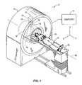
- FIG. 1is a perspective view of a radiation therapy treatment system.
- FIG. 2is a perspective view of a multi-leaf collimator that can be used in the radiation therapy treatment system illustrated in FIG. 1 .
- FIG. 3is a perspective view of a patient support device for use with the system of FIG. 1 .
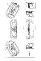
- FIG. 4is an exploded view of a table assembly of the patient support device of FIG. 3 .
- FIG. 5is a perspective view of an upper support of the table assembly of FIG. 4 .
- FIG. 6is a perspective view of a lower support of the table assembly of FIG. 4 .
- FIG. 7is an assortment of views of a control keypad for use with the patient support device of FIG. 1 .
- FIG. 8is an exploded view of the keypad of FIG. 7 .
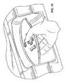
- FIG. 9is a front view of the keypad of FIG. 7 , illustrating the control buttons in greater detail
- FIG. 10is a perspective view of the keypad of FIG. 7 , illustrating operation of the buttons by the operator of the patient support device
- FIG. 11is a perspective view of the patient support device of FIG. 3 , shown in the lowered position.
- FIG. 12illustrates a riser of the patient support device of FIG. 3 .
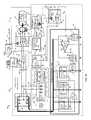
- FIG. 13is a schematic view of an exemplary motor control system according to the present invention.
- FIG. 14is an equivalent schematic illustrating a method of an exemplary motor control system with the motor working in free running mode as motor-turned-generator under the control of an emergency dynamic braking control unit according to the present invention.
- FIG. 15is an equivalent schematic illustrating a method of an exemplary Thevenin equivalent of the motor AC voltage source with conversion to DC voltage source V TH1 .
- FIG. 16is an equivalent schematic illustrating a method of an exemplary Thevenin equivalent resistance of the R M , R AC-DC , and R ACL with conversion to R TH1 .
- FIG. 17is an equivalent schematic illustrating a method of an exemplary Thevenin equivalent of the DC voltage source V TH1 with conversion to voltage source V VSL .
- FIG. 18is an equivalent schematic illustrating a method of an exemplary Thevenin equivalent resistance of the R TH1 and R VSL with conversion to R SE sensor equivalent.
- FIG. 19is a schematic illustrating a method of an exemplary motor control system when the motor is working in free running mode under control of the emergency dynamic braking control unit when an analog computer load is active.
- FIG. 20is a diagram illustrating an exemplary force distribution between external P EXT and system mechanical P INT and electrodynamic P ED resistance forces.
- FIG. 21is a graph illustrating various curves of the mechanical non-linear variable external load.
- FIG. 22is a graph illustrating the curves of the equivalent voltage source V VSL , voltages V CSL , and time charge t CH on the current sensor load C CSL under different values of external loads P EXT .
- FIG. 23is a graph illustrating the current on the passive dynamic loads and current on the controlled dynamic loads under different values of external loads P EXT .
- FIG. 24is a graph illustrating a method of the motor speed control under different values of external loads P EXT .
- FIGS. 25-27are a flowchart and comments illustrating an embodiment of a method of the present invention.
- embodiments of the inventioninclude hardware, software, and electronic components or modules that, for purposes of discussion, may be illustrated and described as if the majority of the components were implemented solely in hardware.
- the electronic based aspects of the inventionmay be implemented in software.
- a plurality of hardware and software based devices, as well as a plurality of different structural componentsmay be utilized to implement the invention.
- the specific mechanical configurations illustrated in the drawingsare intended to exemplify embodiments of the invention and that other alternative mechanical configurations are possible.
- FIG. 1illustrates a radiation therapy treatment system 10 that can provide radiation therapy to a patient 14 .
- the radiation therapy treatmentcan include photon-based radiation therapy, brachytherapy, electron beam therapy, proton, neutron, or particle therapy, or other types of treatment therapy.
- the radiation therapy treatment system 10includes a gantry 18 .
- the gantry 18can support a radiation module 22 , which can include a radiation source 24 and a linear accelerator 26 (a.k.a. “a linac”) operable to generate a beam 30 of radiation.
- a linaclinear accelerator 26
- the gantry 18 shown in the drawingsis a ring gantry, i.e., it extends through a full 360° arc to create a complete ring or circle, other types of mounting arrangements may also be employed.
- a C-type, partial ring gantry, or robotic armcould be used. Any other framework capable of positioning the radiation module 22 at various rotational and/or axial positions relative to the patient 14 may also be employed.
- the radiation source 24may travel in path that does not follow the shape of the gantry 18 .
- the radiation source 24may travel in a non-circular path even though the illustrated gantry 18 is generally circular-shaped.
- the gantry 18 of the illustrated embodimentdefines a gantry aperture 32 into which the patient 14 moves during treatment.
- the radiation module 22can also include a modulation device 34 operable to modify or modulate the radiation beam 30 .
- the modulation device 34provides the modulation of the radiation beam 30 and directs the radiation beam 30 toward the patient 14 .
- the radiation beam 30is directed toward a portion 38 of the patient.
- the portion 38may include the entire body, but is generally smaller than the entire body and can be defined by a two-dimensional area and/or a three-dimensional volume.
- a portion or area desired to receive the radiationwhich may be referred to as a target or target region, is an example of a region of interest.
- Another type of region of interestis a region at risk. If a portion includes a region at risk, the radiation beam is preferably diverted from the region at risk.
- Such modulationis sometimes referred to as intensity modulated radiation therapy (“IMRT”).
- IMRTintensity modulated radiation therapy
- the modulation device 34can include a collimation device 42 as illustrated in FIG. 2 .
- the collimation device 42includes a set of jaws 46 that define and adjust the size of an aperture 50 through which the radiation beam 30 may pass.
- the jaws 46include an upper jaw 54 and a lower jaw 58 .
- the upper jaw 54 and the lower jaw 58are moveable to adjust the size of the aperture 50 .
- the position of the jaws 46regulates the shape of the beam 30 that is delivered to the patient 14 .
- the modulation device 34can comprise a multi-leaf collimator 62 (a.k.a. “MLC”), which includes a plurality of interlaced leaves 66 operable to move from position to position, to provide intensity modulation. It is also noted that the leaves 66 can be moved to a position anywhere between a minimally and maximally-open position. The plurality of interlaced leaves 66 modulate the strength, size, and shape of the radiation beam 30 before the radiation beam 30 reaches the portion 38 on the patient 14 . Each of the leaves 66 is independently controlled by an actuator 70 , such as a motor or an air valve so that the leaf 66 can open and close quickly to permit or block the passage of radiation. The actuators 70 can be controlled by a computer 74 and/or controller.
- MLCmulti-leaf collimator 62
- the actuators 70can be controlled by a computer 74 and/or controller.
- the radiation therapy treatment system 10can also include a detector 78 , e.g., a kilovoltage or a megavoltage detector, operable to receive the radiation beam 30 , as illustrated in FIG. 1 .
- the linear accelerator 26 and the detector 78can also operate as a computed tomography (CT) system to generate CT images of the patient 14 .
- CTcomputed tomography
- the linear accelerator 26emits the radiation beam 30 toward the portion 38 in the patient 14 .
- the portion 38absorbs some of the radiation.
- the detector 78detects or measures the amount of radiation absorbed by the portion 38 .
- the detector 78collects the absorption data from different angles as the linear accelerator 26 rotates around and emits radiation toward the patient 14 .
- the collected absorption datais transmitted to the computer 74 to process the absorption data and to generate images of the patient's body tissues and organs.
- the imagescan also illustrate bone, soft tissues, and blood vessels.
- the system 10can also include a patient support device, shown as a couch 82 , operable to support at least a portion of the patient 14 during treatment. While the illustrated couch 82 is designed to support the entire body of the patient 14 , in other embodiments of the invention the patient support need not support the entire body, but rather can be designed to support only a portion of the patient 14 during treatment.
- the couch 82moves into and out of the field of radiation along an axis 84 (i.e., Y axis).
- the couch 82is also capable of moving along the X and Z axes as illustrated in FIG. 1 .
- the couch 82includes a table assembly 92 coupled to a base 93 via a platform 95 .
- the table assembly 92includes an upper support 94 movably coupled to a lower support 98 .
- the upper support 94is a substantially flat, rectangular support member on which the patient is supported during treatment.
- the upper support 94is movable with respect to the lower support 98 to move the patient into and out of the radiation beam 30 during treatment.
- the upper and lower supports 94 , 98are composed of a carbon fiber composite, though other suitable compositions of the supports are possible.
- the upper support 94includes an upper surface 102 and a lower surface 106 that contacts an upper surface 110 of the lower support 98 .
- the lower surface 106includes a bearing layer 114 that is intended to reduce friction between the lower surface 106 and the upper surface 110 of the lower support 98 when the upper support 94 is moved with respect to the lower support 98 .
- Specific details of the bearing layer 114 and its applicationare discussed in co-pending U.S. patent application Ser. No. 12/204,617, the entire contents of which are incorporated herein by reference.
- the table assembly 92is movable in the X, Y, and Z directions, as illustrated in FIG. 1 . Positioning of the table assembly 92 , and thus the position of the patient, with respect to the gantry 18 and the radiation beam 30 must be precise to ensure that the radiation is delivered to the proper areas of the patient. The movement of the table assembly 92 is controlled by the couch operator using a control keypad 140 , illustrated in FIGS. 7-10 .
- the table assembly 92will move at the direction of the user.
- a hydraulic lifting systemis utilized to move the table assembly 92 in the Z direction.
- the hydraulic lifting systemis a convenient way to achieve some control over the lowering of the table assembly 92 , and has the benefit of allowing the table assembly 92 to be lowered when there is no power delivered to the system 10 .
- the table assembly 92needs to be lowered to allow the patient to exit the couch, and such lowering must be done in a controlled manner.
- hydraulic systemsare more expensive to implement, are less reliable, and are less accurate in their range of motion.
- the couch 82includes a lowering mechanism 160 with resistive braking capabilities to allow for the controlled lowering of the table assembly 92 in powered off situations. More specifically, the lowering mechanism 160 utilizes an electromechanical roller screw configuration. This configuration has the benefits of being less expensive to implement, being more reliable (e.g., the reliability of a roller screw implementation), and allowing for more accurate control of couch motion and position than the conventional hydraulic lifting mechanisms.
- the lowering mechanism 160 as described hereinis responsible for motion in the vertical direction (i.e., the Z direction).
- the lowering mechanism 160includes power braking resistors to dissipate energy from a motor 170 to control the downward motion of the table assembly 92 .
- the braking resistorsact as a damping or deceleration device, taking the energy output of the motor 170 and allowing for controlled lowering of the table assembly 92 , even in the powered off situation. This allows for regulated control of a free running motor that provides linear motion of the mechanical system under nonlinear external loads, even if the power to the system is interrupted.
- the braking resistorsare designed so that no matter the load on the table assembly 92 , the downward speed of the table assembly 92 remains the same. By keeping the speed constant, even with a dynamic load, control of the motion is achieved.
- the motor 170becomes a generator during the lowering process of the table assembly 92 (i.e., if the power is uncontrolled, the power and speed increase as the couch drops). To prevent this, there needs to be a change in the load resistance applied proportionately to the power generated. When the generator has too high of a load, it begins braking. The effective value of the resistance is changed by connecting and disconnecting a power resistor. If the power resistor were constantly applied to the lowering mechanism 160 , the speed of the table assembly 92 would increase as the table assembly 92 is lowered (simulating a free fall) that could cause the table assembly 92 to crash at the bottom of the path of motion.
- the table assembly 92By alternating the connection of the power resistor to the lowering mechanism 160 , the table assembly 92 is protected from crashing. By applying a non-linear load to the lowering mechanism 160 , the speed drop of the table assembly 92 is linear such that the resistance linearizes what was previously non-linear motion. The frequency with which the power resistor is connected to the lowering mechanism 160 changes the effective resistance within the braking circuitry.
- the lowering mechanism 160also includes support arms 164 that couple the table assembly 92 to a riser 168 of the base 93 .
- the lowering mechanism 160includes two pairs of support arms 164 , with each arm 164 within a pair of arms being parallel to the other.
- a longitudinal axis of each arm 164 within a pairremains parallel to the other arm, and a plane P 1 formed by the longitudinal axis of one pair of arms does not intersect a plane P 2 formed by the longitudinal axis of the other pair of arms.
- Movement of the table assembly 92 in the Z axisutilizes an electromechanical roller screw.
- the Z axis motionis controlled by a dual feedback mechanism. Incremental feedback is provided by the roller screw, and a direct drive encoder looks at angle and provides absolute feedback. All axes of the couch 82 have step-move capabilities due to their control mechanisms. In the Z direction, doing a step-move will correct for cobra motion in the Y axis direction.
- the lowering mechanism 160includes a motor control system 169 as illustrated in FIG. 13 .
- the motor control system 169includes the motor 170 and motor controller 198 , which controls the motor 170 in both the regular mode and in the case of the free-running motor-turned-generator mode under the mechanical non-linear variable external load P EXT 174 when the main power (3-Phase AC bus 178 and system VDC bus 182 ) to the couch 82 is interrupted.
- FIG. 21is a graph illustrating various curves of the mechanical non-linear variable external load 174 (P EXT ).
- the motor control system 169includes a system enable interlock 186 where pin 1 is connected to SYS enable bus 190 , pin 2 is connected to system VDC bus 182 , pin 3 is connected through the enable bus 194 to pin 5 of the motor controller 198 , and pin 4 is connected through bus 202 to a coil 206 d of a motor power switch 206 and to a coil 210 c of a motor brake release (MBR) interlock switch 210 .
- MLRmotor brake release
- the motor controller 198includes pin 1 , pin 2 , and pin 3 connected to the 3-Ph AC bus 178 , pin 4 connected to system VDC bus 182 , pin 6 connected through bus 214 to normally-open contact 210 a of the MBR interlock switch 210 , and pin 7 , pin 8 , and pin 9 connected through 3-Phase Motor Controller Bus 218 to appropriate normally-open contacts 206 a , 206 b , 206 c of the motor power switch 206 .
- the motor 170is connected through a shaft 222 to the mechanical non-linear variable external load P EXT 174 .
- a three-phase power bus 226connects the motor 170 to the appropriate common contacts 206 a , 206 b , 206 c of the motor power switch 206 .
- the motor 170includes a motor brake release (MBR) 230 connected through bus 234 to common contact 210 a of the MBR interlock switch 210 .
- MBRmotor brake release
- the motor control system 169also includes an emergency dynamic braking control unit 238 connected through 3-Phase Power bus 242 to appropriate normally-closed contacts 206 a , 206 b , and 206 c of the motor power switch 206 .
- a delta connected 3-Phase resistive dynamic load 246is connected to appropriate phases of the 3-Phase power bus 242 .
- a star connected 3-Phase capacitive dynamic load 250is connected to appropriate phases of the 3-Phase power bus 242 .
- a 3-Phase rectifier 254with common points of diodes D 1 -D 4 , D 2 -D 5 , and D 3 -D 6 , is connected to appropriate phases of the 3-Phase Power bus 242 .
- the common points of the diodes D 4 , D 5 , D 6are connected to ground and the common points of the diodes D 1 , D 2 , D 3 are connected to the power-control-sensor bus 258 .
- the power-control-sensor bus 258is connected to a voltage sensor dynamic load 262 (R VSL ), and the other side of the R VSL is connected to ground.
- the power-control-sensor bus 258is also connected to a current sensor dynamic load 266 (C CSL ), and the other side of the C CSL is connected to ground.
- the power-control-sensor bus 258is also connected to a controlled dynamic load 270 (R CDL ).
- the other side of the R CDLis connected to a normally-open contact of a power switch 274 , while the common contact of the power switch 274 is connected to ground.
- the power-control-sensor bus 258also is connected to a positive input of an operation amplifier 278 .
- the emergency dynamic braking control unit 238includes an emergency power supply 282 , which contains two rechargeable batteries BT 1 , BT 2 connected in series.
- the negative lead of the battery BT 1is connected to ground and the positive lead of the battery BT 2 is connected through bus 286 to common contact 210 b of the MBR interlock switch 210 .
- the normally closed contact 210 bis connected through bus 290 to the normally open contact of an emergency motor brake release switch 294 .
- the common contact of this switch 294is connected through bus 298 to coil 302 c of a system VDC interlock switch 302 and to normally closed contact 210 a of the MBR interlock switch 210 .
- the common point of the batteries BT 1 and BT 2are connected through bus 306 to normally open contact 302 b of the system VDC interlock switch 302 .
- the common contact 302 ais connected to system VDC through bus 182 and normally closed contact 302 a is connected to coil 210 c of the MBR interlock switch 210 through bus 362 .
- Common contact 302 bis connected to bus 310 , which supplies analog computer load 314 and is connected to pin 1 of a voltage reference 318 , to pin 1 of the operation amplifier 278 , and to pin 1 of a switched oscillator 322 .
- the voltage reference 318is connected by pin 2 to ground and is connected by pin 3 through bus 326 to the negative input of the operation amplifier 278 .
- the operation amplifier 278is connected by pin 2 to ground and is connected by pin 3 through bus 330 to pin 3 of the switched oscillator 322 .
- the switched oscillator 322is connected by pin 2 to ground and is connected by pin 4 through bus 334 to pin 1 of the power switch 274 .
- the motor 170is initiated when it receives a signal from the 3-Phase AC power on the bus 178 , system VDC on the bus 182 , and SYS enable signal on the bus 190 .
- the system enable interlock 186initiates the motor controller 198 , the motor power switch 206 , the MBR interlock switch 210 , and the system VDC interlock switch 302 through normally closed contact 302 a .
- the motor controller 198communicates with the motor 170 through the bus 218 , normally open contacts 206 a , 206 b , 206 c of the motor power switch 206 , and bus 226 .
- the motor 170begins acting through shaft 222 on the mechanical non-linear variable external load P EXT 174 .
- the motor controller 198also communicates with the motor brake release 230 through bus 214 , normally open contact 210 a , and bus 234 to disengage the motor brake release 230 .
- bus 214normally open contact 210 a
- bus 234to disengage the motor brake release 230 .
- the motor 170is connected to the emergency dynamic braking control unit 238 through bus 226 , normally closed contacts 206 a , 206 b , 206 c , and through 3-Phase power bus 242 .
- the MBR release switch 294is activated through bus 298 to engaged coil 302 c of the system VDC interlock switch 302 , and to switch 302 by contact 302 a to disengaged coil 210 c of the MBR interlock switch 210 .
- the motoris reactivated when the MBR 230 is disengaged.
- the MBR 230is disengaged when the MBR release switch 294 is released through bus 298 , normally closed contact 210 a , and bus 234 .
- the motor 170begins acting under external load P EXT 174 , and the 3-Phase AC voltage from the motor 170 begins to interact with Passive Dynamic Loads 338 .
- the motor 170gets first two stages of dynamic braking action on the AC Dynamic Loads 342 of the Passive Dynamic Loads 338 .
- the AC Dynamic Loads 342includes two types of AC loads: (1) the 3-Phase Resistive Dynamic Load 246 which transfers AC energy from the motor into heat, and (2) the 3-Phase Capacitive Dynamic Load 250 which shifts AC phases from the motor 170 . Both heat dissipation and phase shift increases current from the motor 170 and this current increases eddy currents in the motor 170 which affect braking action in the motor 170 .
- the motor 170continuously increases speed under P EXT 174 until the AC voltage from the motor reaches a certain value, and then the AC voltage begins rectification by 3-Phase Rectifier 254 .
- the rectified AC voltagebegins a third stage in the DC passive dynamic braking on the Voltage Sensor Dynamic Load 262 (V VSL ) of the Passive Dynamic Loads 338 .
- the motor 170proceeds to increase speed under P EXT 174 and the DC voltage increases too, until a certain value is reached, and then the Analog Computer Load 314 begins to control the dynamic braking action.
- the Analog Computer Load 314is supplied by two sources: (1) the Emergency Power Supply 282 through BT 1 , through bus 306 , normally open contact 302 b , and bus 310 , and (2) motor 170 through bus 226 , normally closed contacts 206 a , 206 b , 206 c , bus 242 , 3-Phase Rectifier 254 , and Power-Control-Sensor Bus 258 .
- Condition 1xV RF >V VSL (1)
- FIG. 22is a graph illustrating the curves of the equivalent voltage source V VSL , voltages V CSL , and time charge t CH on the current sensor load C CSL under different values of external loads P EXT .
- the time charge t CH of the capacitor C CSL 266 up to value of the voltage xV RFis illustrated in FIG. 19 and determined by
- R SEis the resistance of the sensor equivalent, which is calculated by formula (4) illustrated in FIG. 16 and formula (5) illustrated in FIG. 18 .
- R SErepresents the internal resistance of the motor 170 with relationship to the P EXT 174 ;
- V VSLis the Thevenin voltage source equivalent of the Motor 170 which is calculated by formula (6) illustrated in FIG. 15 and formula (7) illustrated in FIG. 17 .
- nis determined by formula (8) (provided below) illustrated in FIG. 20 .
- nP INT P EXT ( 8 )
- nis a mechanical system coefficient
- n0 . . . 1 (n is a positive number)
- P INTis a system mechanical internal resistance 350
- P EXTis a mechanical non-linear variable external load 174
- xV RFis the value of the Voltage Reference 318
- xis an adjusting coefficient which allows adjustment of the Emergency Dynamic Braking Control Unit 238 for different motors and different values of the braking speed control.
- FIG. 23is a graph illustrating the current on the passive dynamic loads and current on the controlled dynamic loads under different values of external loads P EXT .
- I CSLillustrated in FIG. 19
- of the Current Sensor Dynamic Load 266is directly proportional to the value of the P EXT 174 I CSL ⁇ P EXT (9)
- the operation amplifier 278controls changes of the voltage on the Capacitor Sensor Dynamic Load (C CSL ) 262 and compares it with the value of the voltage on the Voltage Reference (xV RF ) 318 .
- the operation Amplifier 278starts Switched Oscillator 322 .
- the Switched Oscillator 322is switched with a predetermined time t DDCH of the Power Switch 274 .
- the Power Switch 274connects the Controlled Dynamic Load 270 to ground, which begins the fourth stage of the dynamic braking action of the motor 170 on the Controlled Dynamic Load 270 .
- the Controlled Dynamic Load 270discharges Capacitor C CSL of the Current Sensor Dynamic Load 266 .
- the predetermined time discharge t DDCHshould be greater than the time constant of the discharge capacitor C CSL
- the operation amplifier 278continuously compares the C CSL voltage with value of the voltage on the Voltage Reference 318 (x VRF ) until the voltage x VRF becomes equal to or higher than the value C CSL 262 .
- the Switched Oscillator 322disconnects Power Switch 274 , which disconnects R CDL 270 from ground, which begins the fifth stage of the dynamic braking action of the motor 170 on the Current Sensor Dynamic Load 266 (C CSL ).
- the instantaneous current I INST through the capacitor of the Current Sensor Dynamic Load 266 (C CSL )is determined by:
- I INSTC CSL * V CSL C CSL * R SE * e ( n - V VSL xV RF ) ( 11 )
- the Operation Amplifier 278restarts the Switched Oscillator 322 .
- the Switched Oscillator 322is switched with predetermined time t DDCH of the Power Switch 274 .
- the Power Switch 274is connected to Controlled Dynamic Load 270 to ground, which again begins the fourth stage of the dynamic braking action of the motor 170 on the Controlled Dynamic Load 270 .
- the Controlled Dynamic Load 270discharges the capacitor of the Current Sensor Dynamic Load 266 (C CSL ).
- FIG. 24is a graph illustrating the motor speed control under different values of external loads P EXT .
- a motor-turned-generator 170is a source for generating braking forces and a source of information about its conditions.
- V CSLvoltage sensor dynamic load 262
- C CSLcurrent sensor dynamic load 266
- the capacitor of the current sensor dynamic load 266is not a reactive load with respect to the motor 170 because the capacitor is charged from the motor 170 and is discharged through a resistor(s) of the controlled dynamic load 270 , which means that the capacitor does not return charged energy back to the motor 170 .
- the capacitorcontinues to be non-linear load.
- the controlled dynamic loads 346include a two-cycle controlled dynamic load which provides a two-cycle controlled dynamic braking action on the motor 170 .
- the first cycleis controlled by the controlled dynamic load 270 , which provides the dynamic braking action on the motor 170 and discharges the capacitor of the current sensor dynamic load 266 (C CSL ) during predetermined time t DDCH .
- the second cycleis controlled by the current sensor dynamic load 266 , which provides dynamic braking action on the motor 170 during the charge time t CH of the capacitor of the current sensor dynamic load 266 .
- motor 170When motor 170 operates as a motor-turned-generator it has the following properties:
- the analog computer load 314includes combined properties of the analog computer and the controlled dynamic loads.
- FIGS. 25-27are a flowchart and comments illustrating an embodiment of a method of the present invention.
Landscapes
- Health & Medical Sciences (AREA)
- Life Sciences & Earth Sciences (AREA)
- Engineering & Computer Science (AREA)
- Medical Informatics (AREA)
- Radiology & Medical Imaging (AREA)
- Biomedical Technology (AREA)
- Biophysics (AREA)
- High Energy & Nuclear Physics (AREA)
- Veterinary Medicine (AREA)
- Nuclear Medicine, Radiotherapy & Molecular Imaging (AREA)
- Optics & Photonics (AREA)
- Pathology (AREA)
- Public Health (AREA)
- Physics & Mathematics (AREA)
- Heart & Thoracic Surgery (AREA)
- Molecular Biology (AREA)
- Surgery (AREA)
- Animal Behavior & Ethology (AREA)
- General Health & Medical Sciences (AREA)
- Human Computer Interaction (AREA)
- Power Engineering (AREA)
- Radiation-Therapy Devices (AREA)
- Stopping Of Electric Motors (AREA)
- Rehabilitation Tools (AREA)
Abstract
Description
Condition 1: xVRF>VVSL (1)
Condition 2: xVRF<VVSL (2)
ICSL∥PEXT (9)
- (a) Voltage Sensor Dynamic Load262 (VCSL) is the DC passive load of the system Passive Dynamic Loads338, and the voltage sensor recognizes the internal resistance of the
motor 170 like a voltage drop on itself. - (b) Current Sensor Dynamic Load266 (CCSL) is a three function device: the integrator in the
analog computer load 314, a current sensor, which recognizes the current value of themotor 170 as a time charge of the capacitor up to a certain value on the Voltage Reference318 (xVRF), and the controlled dynamic load in theanalog computer load 314.
- (a) Voltage Sensor Dynamic Load262 (VCSL) is the DC passive load of the system Passive Dynamic Loads338, and the voltage sensor recognizes the internal resistance of the
- (a) The passive
dynamic load 338 comprises the ACdynamic load 342, which includes the 3-Ph capacitive dynamic load250 (passive braking—stage 1) and the 3-Ph resistive dynamic load246 (passive braking—stage 2) and the DC dynamic load, which includes the voltage sensor dynamic load262 (passive braking—stage 3). - (b) The controlled
dynamic load 346 includes the controlled dynamic load270 (controlled braking—stage 4) and the current sensor dynamic load266 (controlled braking—stage 5).
- (a) The passive
- (a) the
motor 170 becomes a voltage source; - (b) the internal resistance of the voltage source is variable and inversely proportional to the speed of the motor and the mechanical load on the motor. In this mode, the
motor 170 works like a sensor where the voltage reflects the speed of the motor and the current reflects the mechanical load on theshaft 222 of the motor.
- (a) the
Claims (10)
Priority Applications (2)
| Application Number | Priority Date | Filing Date | Title |
|---|---|---|---|
| US12/204,628US7784127B2 (en) | 2007-09-04 | 2008-09-04 | Patient support device and method of operation |
| US12/872,288US8161585B2 (en) | 2007-09-04 | 2010-08-31 | Patient support device and method of operation |
Applications Claiming Priority (2)
| Application Number | Priority Date | Filing Date | Title |
|---|---|---|---|
| US96990407P | 2007-09-04 | 2007-09-04 | |
| US12/204,628US7784127B2 (en) | 2007-09-04 | 2008-09-04 | Patient support device and method of operation |
Related Child Applications (1)
| Application Number | Title | Priority Date | Filing Date |
|---|---|---|---|
| US12/872,288DivisionUS8161585B2 (en) | 2007-09-04 | 2010-08-31 | Patient support device and method of operation |
Publications (2)
| Publication Number | Publication Date |
|---|---|
| US20090056021A1 US20090056021A1 (en) | 2009-03-05 |
| US7784127B2true US7784127B2 (en) | 2010-08-31 |
Family
ID=40405182
Family Applications (4)
| Application Number | Title | Priority Date | Filing Date |
|---|---|---|---|
| US12/204,628ActiveUS7784127B2 (en) | 2007-09-04 | 2008-09-04 | Patient support device and method of operation |
| US12/204,617AbandonedUS20090070935A1 (en) | 2007-09-04 | 2008-09-04 | Patient support device |
| US12/204,641ActiveUS8122542B2 (en) | 2007-09-04 | 2008-09-04 | Patient support device |
| US12/872,288ActiveUS8161585B2 (en) | 2007-09-04 | 2010-08-31 | Patient support device and method of operation |
Family Applications After (3)
| Application Number | Title | Priority Date | Filing Date |
|---|---|---|---|
| US12/204,617AbandonedUS20090070935A1 (en) | 2007-09-04 | 2008-09-04 | Patient support device |
| US12/204,641ActiveUS8122542B2 (en) | 2007-09-04 | 2008-09-04 | Patient support device |
| US12/872,288ActiveUS8161585B2 (en) | 2007-09-04 | 2010-08-31 | Patient support device and method of operation |
Country Status (5)
| Country | Link |
|---|---|
| US (4) | US7784127B2 (en) |
| EP (3) | EP2185075A4 (en) |
| JP (3) | JP2010537783A (en) |
| CN (3) | CN101815471A (en) |
| WO (3) | WO2009032935A2 (en) |
Cited By (35)
| Publication number | Priority date | Publication date | Assignee | Title |
|---|---|---|---|---|
| US20100134315A1 (en)* | 2005-06-07 | 2010-06-03 | Koninklijke Philips Electronics, N.V. | Fail-safe remote control |
| US20100146704A1 (en)* | 2006-11-21 | 2010-06-17 | Hans-Peter Barthelt | Fail-Proof Control For Hospital Beds |
| US20110107515A1 (en)* | 2009-09-29 | 2011-05-12 | Brunker Bradley J | Patient support device with low attenuation properties |
| US8344340B2 (en) | 2005-11-18 | 2013-01-01 | Mevion Medical Systems, Inc. | Inner gantry |
| US8581523B2 (en) | 2007-11-30 | 2013-11-12 | Mevion Medical Systems, Inc. | Interrupted particle source |
| US8763178B1 (en)* | 2009-08-19 | 2014-07-01 | Martin Manufacturing Co., Llc | Low profile patient examination table |
| US8791656B1 (en) | 2013-05-31 | 2014-07-29 | Mevion Medical Systems, Inc. | Active return system |
| US8927950B2 (en) | 2012-09-28 | 2015-01-06 | Mevion Medical Systems, Inc. | Focusing a particle beam |
| US8933650B2 (en) | 2007-11-30 | 2015-01-13 | Mevion Medical Systems, Inc. | Matching a resonant frequency of a resonant cavity to a frequency of an input voltage |
| US8952634B2 (en) | 2004-07-21 | 2015-02-10 | Mevion Medical Systems, Inc. | Programmable radio frequency waveform generator for a synchrocyclotron |
| US9155186B2 (en) | 2012-09-28 | 2015-10-06 | Mevion Medical Systems, Inc. | Focusing a particle beam using magnetic field flutter |
| US9185789B2 (en) | 2012-09-28 | 2015-11-10 | Mevion Medical Systems, Inc. | Magnetic shims to alter magnetic fields |
| US9301384B2 (en) | 2012-09-28 | 2016-03-29 | Mevion Medical Systems, Inc. | Adjusting energy of a particle beam |
| US9443633B2 (en) | 2013-02-26 | 2016-09-13 | Accuray Incorporated | Electromagnetically actuated multi-leaf collimator |
| US9545528B2 (en) | 2012-09-28 | 2017-01-17 | Mevion Medical Systems, Inc. | Controlling particle therapy |
| US9622335B2 (en) | 2012-09-28 | 2017-04-11 | Mevion Medical Systems, Inc. | Magnetic field regenerator |
| US9661736B2 (en) | 2014-02-20 | 2017-05-23 | Mevion Medical Systems, Inc. | Scanning system for a particle therapy system |
| US9681531B2 (en) | 2012-09-28 | 2017-06-13 | Mevion Medical Systems, Inc. | Control system for a particle accelerator |
| US9723705B2 (en) | 2012-09-28 | 2017-08-01 | Mevion Medical Systems, Inc. | Controlling intensity of a particle beam |
| US9730308B2 (en) | 2013-06-12 | 2017-08-08 | Mevion Medical Systems, Inc. | Particle accelerator that produces charged particles having variable energies |
| US9950194B2 (en) | 2014-09-09 | 2018-04-24 | Mevion Medical Systems, Inc. | Patient positioning system |
| US9962560B2 (en) | 2013-12-20 | 2018-05-08 | Mevion Medical Systems, Inc. | Collimator and energy degrader |
| US10149794B2 (en)* | 2013-06-14 | 2018-12-11 | Eschmann Holdings Limited | Surgical table and method of operating the same |
| US10254739B2 (en) | 2012-09-28 | 2019-04-09 | Mevion Medical Systems, Inc. | Coil positioning system |
| US10258810B2 (en) | 2013-09-27 | 2019-04-16 | Mevion Medical Systems, Inc. | Particle beam scanning |
| US10646728B2 (en) | 2015-11-10 | 2020-05-12 | Mevion Medical Systems, Inc. | Adaptive aperture |
| US10653892B2 (en) | 2017-06-30 | 2020-05-19 | Mevion Medical Systems, Inc. | Configurable collimator controlled using linear motors |
| US10675487B2 (en) | 2013-12-20 | 2020-06-09 | Mevion Medical Systems, Inc. | Energy degrader enabling high-speed energy switching |
| US10702715B2 (en) | 2016-11-15 | 2020-07-07 | Reflexion Medical, Inc. | Radiation therapy patient platform |
| US10925147B2 (en) | 2016-07-08 | 2021-02-16 | Mevion Medical Systems, Inc. | Treatment planning |
| US11103730B2 (en) | 2017-02-23 | 2021-08-31 | Mevion Medical Systems, Inc. | Automated treatment in particle therapy |
| US11291861B2 (en) | 2019-03-08 | 2022-04-05 | Mevion Medical Systems, Inc. | Delivery of radiation by column and generating a treatment plan therefor |
| US20230022716A1 (en)* | 2021-07-20 | 2023-01-26 | Mevion Medical Systems, Inc. | Gantry having a retractable cover |
| US20230101051A1 (en)* | 2021-09-29 | 2023-03-30 | Hitachi, Ltd. | Radiation treatment system and method of operating radiation treatment system |
| US12440703B2 (en) | 2021-11-15 | 2025-10-14 | Reflexion Medical, Inc. | Radiation therapy patient platform |
Families Citing this family (28)
| Publication number | Priority date | Publication date | Assignee | Title |
|---|---|---|---|---|
| WO2009032935A2 (en)* | 2007-09-04 | 2009-03-12 | Tomotherapy Incorporated | Patient support device |
| DE102009033304A1 (en) | 2009-07-15 | 2011-01-27 | Siemens Aktiengesellschaft | Computer tomography detector with high radiation resistance |
| CN102068265B (en)* | 2009-11-25 | 2014-11-12 | Ge医疗系统环球技术有限公司 | Rotating mechanism for chest stand as well as chest stand and shooting machine thereof |
| US20110154569A1 (en)* | 2009-12-28 | 2011-06-30 | Varian Medical Systems, Inc. | Mobile patient support system |
| US20120215360A1 (en)* | 2011-02-21 | 2012-08-23 | Zerhusen Robert M | Patient support with electronic writing tablet |
| CN103429159B (en)* | 2011-03-09 | 2016-08-10 | 皇家飞利浦有限公司 | Imaging system subject support |
| KR101205891B1 (en)* | 2011-09-26 | 2012-11-28 | 한국과학기술연구원 | Electrode placement device for stereotactic surgery |
| CN103027817B (en)* | 2011-09-30 | 2016-08-17 | Ge医疗系统环球技术有限公司 | Bed board drive mechanism, sick bed and imaging patients and transmission equipment |
| DE102012203133A1 (en) | 2012-02-29 | 2013-08-29 | Siemens Aktiengesellschaft | Patient storage device and a medical imaging device comprising the patient support device |
| DE102012203766A1 (en)* | 2012-03-09 | 2013-09-12 | Siemens Aktiengesellschaft | Positioning aid for e.g. computed tomography (CT) apparatus, has laser pointer which is aligned such that optical path of laser pointer or its rectilinear extrapolation is aligned parallel to tunnel axis or tangential to tunnel wall |
| DE102012213390A1 (en)* | 2012-07-31 | 2014-02-06 | Siemens Aktiengesellschaft | Patient positioning device and a positioning method for positioning a head of a patient within a surgical head attachment unit |
| US20140276017A1 (en)* | 2013-03-14 | 2014-09-18 | Volcano Corporation | System for guiding workflow during a medical imaging procedure |
| CN104337539A (en)* | 2013-08-01 | 2015-02-11 | 上海联影医疗科技有限公司 | System for adjusting moving speed of sickbed |
| CN107374748B (en)* | 2013-10-29 | 2020-12-01 | 上海联影医疗科技股份有限公司 | Scanning bed position control system |
| JP6282562B2 (en)* | 2014-09-05 | 2018-02-21 | 住友重機械工業株式会社 | Neutron capture therapy system |
| US10548532B2 (en)* | 2014-11-12 | 2020-02-04 | Shanghai United Imaging Healthcare Co., Ltd. | Transport apparatus in medical system |
| CN105204285A (en)* | 2015-10-07 | 2015-12-30 | 张善华 | Holographic projection type radiographic imaging instrument |
| CN108366898A (en)* | 2015-12-11 | 2018-08-03 | 美好罗伯特有限公司 | Robot bed |
| WO2017099234A1 (en)* | 2015-12-11 | 2017-06-15 | 株式会社メディカロイド | Medical system |
| US10694976B2 (en)* | 2017-05-04 | 2020-06-30 | Elekta Ltd. | Squeeze protection |
| BR112021003450A2 (en)* | 2018-08-24 | 2021-05-18 | Medical Beam Laboratories, Llc | patient positioning system, radiation beam delivery apparatus, method of delivering a therapeutic dose of radiation to a human or animal patient, and patient positioning device |
| KR102323504B1 (en)* | 2018-10-25 | 2021-11-08 | 사회복지법인 삼성생명공익재단 | Adjustment couch and medical couch system |
| EP3654049A1 (en)* | 2018-11-15 | 2020-05-20 | Koninklijke Philips N.V. | Eddy current brake for patient table of mri |
| CN112972909B (en) | 2019-12-13 | 2023-03-14 | 医科达(北京)医疗器械有限公司 | Controller for radiotherapy equipment |
| AT524523A1 (en)* | 2020-11-30 | 2022-06-15 | B & R Ind Automation Gmbh | Operation of a multi-axis system |
| EP4452077A4 (en)* | 2021-12-23 | 2025-10-15 | Elekta Beijing Medical Systems Co Ltd | PATIENT RECLINING DEVICE FOR A RADIATION THERAPY SYSTEM |
| JP2024059004A (en)* | 2022-10-17 | 2024-04-30 | 株式会社日立製作所 | Radiation therapy couch |
| CN116412219B (en)* | 2023-04-10 | 2025-08-29 | 深圳市金石医疗科技有限公司 | Magnetic resonance imaging bed parking brake assembly, method and system |
Citations (19)
| Publication number | Priority date | Publication date | Assignee | Title |
|---|---|---|---|---|
| US3675099A (en)* | 1971-07-02 | 1972-07-04 | Gen Motors Corp | Induction motor regenerative braking system |
| US3755712A (en)* | 1972-09-07 | 1973-08-28 | Square D Co | Fault protection for dc motor thyristor power supplies |
| US3851233A (en)* | 1972-06-22 | 1974-11-26 | L Sherman | Electro-kinetic, parallel-series, dynamic brake for alternating current motors |
| US3974384A (en)* | 1973-11-12 | 1976-08-10 | Siemens Aktiengesellschaft | X-ray diagnostic apparatus for radioscopy and X-ray film exposures including an X-ray tube having a rotating anode |
| US4354112A (en)* | 1980-11-28 | 1982-10-12 | Tokyo Shibaura Denki Kabushiki Kaisha | X-ray cine radiography apparatus |
| US4987583A (en)* | 1989-04-25 | 1991-01-22 | General Electric Company | Automatic backout control for a motorized positioning X-ray apparatus |
| US5105141A (en)* | 1989-07-13 | 1992-04-14 | General Electric Cgr Sa | Device to control the speed of two-phase or three-phase motors |
| US6094760A (en)* | 1997-08-04 | 2000-08-01 | Sumitomo Heavy Industries, Ltd. | Bed system for radiation therapy |
| US20030107349A1 (en)* | 2000-01-28 | 2003-06-12 | Lawrence Haydock | Ac power generating system |
| US6653806B1 (en)* | 1999-03-18 | 2003-11-25 | Kabushiki Kaisha Yaskawa Denki | Dynamic brake circuit and semiconductor inverter using dynamic brake circuit |
| US6857147B2 (en)* | 2003-03-04 | 2005-02-22 | Ge Medical Systems Global Technology Company, Llc | Synchronization drive for a longitudinal axis telescopic guidance mechanism |
| US20050114996A1 (en)* | 2002-11-26 | 2005-06-02 | Baskar Somasundaram | Multiconfiguration braking system |
| US6906493B1 (en)* | 2004-01-20 | 2005-06-14 | Molon Motor And Coil Corporation | Electronic brake for motor |
| US20050283911A1 (en)* | 2004-06-25 | 2005-12-29 | Roussy Richard B | Leveling system for a height adjustable patient bed |
| US20070093359A1 (en)* | 2005-10-26 | 2007-04-26 | Mitsubishi Denki Kabushiki Kaisha | Vehicular power control apparatus |
| US20070107128A1 (en)* | 2005-11-15 | 2007-05-17 | General Electric Company | Braking system for a positioner in a medical imaging apparatus |
| US20090159677A1 (en)* | 2007-12-20 | 2009-06-25 | General Electric Company | Contactless power and data transfer system and method |
| US7552490B2 (en)* | 2006-01-24 | 2009-06-30 | Accuray Incorporated | Method and apparatus for patient loading and unloading |
| US20090268491A1 (en)* | 2001-12-03 | 2009-10-29 | Igo, Inc. | Power converter with retractable cable system |
Family Cites Families (50)
| Publication number | Priority date | Publication date | Assignee | Title |
|---|---|---|---|---|
| US3348114A (en)* | 1964-05-11 | 1967-10-17 | Westinghouse Electric Corp | Motor drive apparatus with dynamic braking |
| US3497786A (en)* | 1967-08-30 | 1970-02-24 | Picker Corp | Motor speed control circuit |
| US3840221A (en)* | 1973-09-04 | 1974-10-08 | W Hogan | Top-within-top for x-ray table |
| GB1578754A (en)* | 1976-03-25 | 1980-11-12 | Emi Ltd | Patient positioning and supporting arrangement |
| GB1554115A (en)* | 1976-06-28 | 1979-10-17 | Ohio Nuclear | Patient support systems |
| US4145612A (en)* | 1977-08-31 | 1979-03-20 | The Babcock & Wilcox Company | X-ray patient support stretcher and method for fabrication |
| US4880222A (en)* | 1986-04-10 | 1989-11-14 | Picker International, Inc. | Patient support for radiation imaging |
| US5008907A (en) | 1989-05-31 | 1991-04-16 | The Regents Of The University Of California | Therapy x-ray scanner |
| EP0405282A1 (en)* | 1989-06-30 | 1991-01-02 | Siemens Aktiengesellschaft | Apparatus for treatment of a living body with focused shockwaves |
| EP0404998B1 (en)* | 1989-06-30 | 1994-11-09 | Siemens Aktiengesellschaft | Patient-supporting table having a supporting plate adjustable in the length direction of the table |
| JPH04114634A (en)* | 1990-09-04 | 1992-04-15 | Toshiba Corp | medical diagnostic bed |
| US5113420A (en) | 1990-12-24 | 1992-05-12 | Texaco Inc. | Method and apparatus for positioning a sample with repeatable accuracy |
| US5661773A (en) | 1992-03-19 | 1997-08-26 | Wisconsin Alumni Research Foundation | Interface for radiation therapy machine |
| US5317616A (en)* | 1992-03-19 | 1994-05-31 | Wisconsin Alumni Research Foundation | Method and apparatus for radiation therapy |
| US5351280A (en)* | 1992-03-19 | 1994-09-27 | Wisconsin Alumni Research Foundation | Multi-leaf radiation attenuator for radiation therapy |
| DE69416587T2 (en)* | 1993-06-09 | 1999-07-15 | Wisconsin Alumni Research Foundation, Madison, Wis. | RADIATION THERAPY MACHINE FOR GENERATING A DESIRED INTENSITY PROFILE |
| US5446548A (en) | 1993-10-08 | 1995-08-29 | Siemens Medical Systems, Inc. | Patient positioning and monitoring system |
| US6217214B1 (en)* | 1993-11-22 | 2001-04-17 | Hologic, Inc. | X-ray bone densitometry apparatus |
| US5432834A (en) | 1993-11-22 | 1995-07-11 | Hologic, Inc. | Whole-body dual-energy bone densitometry using a narrow angle fan beam to cover the entire body in successive scans |
| EP0673661B1 (en) | 1994-03-25 | 2003-03-12 | Kabushiki Kaisha Toshiba | Radiotherapy system |
| US5754622A (en)* | 1995-07-20 | 1998-05-19 | Siemens Medical Systems, Inc. | System and method for verifying the amount of radiation delivered to an object |
| GB9520564D0 (en)* | 1995-10-07 | 1995-12-13 | Philips Electronics Nv | Apparatus for treating a patient |
| SE505513C2 (en)* | 1995-11-14 | 1997-09-08 | Elekta Ab | Device for repositioning a patient |
| US5657498A (en)* | 1995-11-20 | 1997-08-19 | General Electric Company | Methods and apparatus for acquiring table elevation information |
| US5647663A (en)* | 1996-01-05 | 1997-07-15 | Wisconsin Alumni Research Foundation | Radiation treatment planning method and apparatus |
| US5771513A (en)* | 1996-06-03 | 1998-06-30 | Beta Medical Products, Inc. | X-ray compatible, partially flexible patient support |
| US6155976A (en)* | 1997-03-14 | 2000-12-05 | Nims, Inc. | Reciprocating movement platform for shifting subject to and fro in headwards-footwards direction |
| JPH10258049A (en)* | 1997-03-19 | 1998-09-29 | Hitachi Medical Corp | Bed control device for medical diagnosing device |
| JP3577221B2 (en) | 1997-08-04 | 2004-10-13 | 住友重機械工業株式会社 | Radiation therapy bed system |
| US6152599A (en) | 1998-10-21 | 2000-11-28 | The University Of Texas Systems | Tomotherapy treatment table positioning device |
| DE19933802B4 (en)* | 1999-07-16 | 2004-04-22 | Siemens Ag | storage device |
| DE19955119B4 (en) | 1999-11-16 | 2009-12-24 | Maquet Gmbh & Co. Kg | Patient support plate for a medical examination table |
| US6615428B1 (en) | 2000-10-16 | 2003-09-09 | Ge Medical Systems Global Technology Company, Llc | Dual stage telescoping imaging table |
| US6955464B1 (en)* | 2001-06-01 | 2005-10-18 | Analogic Corporation | Horizontal drive apparatus and method for patient table |
| US6637056B1 (en)* | 2001-06-01 | 2003-10-28 | Analogic Corporation | Lifting apparatus and method for patient table |
| US6754520B2 (en)* | 2001-10-19 | 2004-06-22 | Koninklijke Philips Electronics N.V. | Multimodality medical imaging system and method with patient handling assembly |
| DE10221180A1 (en)* | 2002-05-13 | 2003-12-24 | Siemens Ag | Patient positioning device for radiation therapy |
| US7084597B2 (en)* | 2002-06-03 | 2006-08-01 | Denso Corporation | Motor control apparatus |
| US6929398B1 (en) | 2002-07-11 | 2005-08-16 | Analogic Corporation | Two-piece pallet assembly for patient table |
| US7120223B2 (en)* | 2002-09-25 | 2006-10-10 | Pencilbeam Technologies | Body-supporting couch |
| US7077569B1 (en) | 2002-12-10 | 2006-07-18 | Analogic Corporation | Apparatus and method for supporting pallet extending from patient table |
| US6950492B2 (en)* | 2003-06-25 | 2005-09-27 | Besson Guy M | Dynamic multi-spectral X-ray projection imaging |
| WO2005041835A2 (en) | 2003-10-29 | 2005-05-12 | Tomotherapy Incorporated | System and method for calibrating and positioning a radiation therapy treatment table |
| JP4434701B2 (en) | 2003-11-21 | 2010-03-17 | 株式会社東芝 | Bed equipment |
| US7103931B2 (en) | 2004-08-28 | 2006-09-12 | General Electric Company | Table drive system for medical imaging apparatus |
| US7302038B2 (en)* | 2004-09-24 | 2007-11-27 | Wisconsin Alumni Research Foundation | Correction of patient rotation errors in radiotherapy using couch translation |
| EP1951120A2 (en)* | 2005-11-18 | 2008-08-06 | Koninklijke Philips Electronics N.V. | Systems and methods using x-ray tube spectra for computed tomography applications |
| US20080031414A1 (en) | 2006-04-27 | 2008-02-07 | Qfix Systems, Llc | Method for Creating 3D Coordinate Systems in Image Space for Device and Patient Table Location and Verification |
| US7654382B2 (en)* | 2007-03-26 | 2010-02-02 | General Electric Co. | Table drive system |
| WO2009032935A2 (en) | 2007-09-04 | 2009-03-12 | Tomotherapy Incorporated | Patient support device |
- 2008
- 2008-09-04WOPCT/US2008/075269patent/WO2009032935A2/enactiveApplication Filing
- 2008-09-04CNCN200880105521Apatent/CN101815471A/enactivePending
- 2008-09-04JPJP2010524141Apatent/JP2010537783A/ennot_activeWithdrawn
- 2008-09-04WOPCT/US2008/075260patent/WO2009032927A1/enactiveApplication Filing
- 2008-09-04USUS12/204,628patent/US7784127B2/enactiveActive
- 2008-09-04EPEP08799173Apatent/EP2185075A4/ennot_activeWithdrawn
- 2008-09-04WOPCT/US2008/075267patent/WO2009032933A1/enactiveApplication Filing
- 2008-09-04USUS12/204,617patent/US20090070935A1/ennot_activeAbandoned
- 2008-09-04EPEP08799166Apatent/EP2192859A4/ennot_activeWithdrawn
- 2008-09-04CNCN200880105519Apatent/CN101815470A/enactivePending
- 2008-09-04JPJP2010524143Apatent/JP2010537784A/ennot_activeWithdrawn
- 2008-09-04EPEP08799171Apatent/EP2203118A4/ennot_activeWithdrawn
- 2008-09-04JPJP2010524137Apatent/JP2010537781A/ennot_activeWithdrawn
- 2008-09-04USUS12/204,641patent/US8122542B2/enactiveActive
- 2008-09-04CNCN200880105646Apatent/CN101854865A/enactivePending
- 2010
- 2010-08-31USUS12/872,288patent/US8161585B2/enactiveActive
Patent Citations (19)
| Publication number | Priority date | Publication date | Assignee | Title |
|---|---|---|---|---|
| US3675099A (en)* | 1971-07-02 | 1972-07-04 | Gen Motors Corp | Induction motor regenerative braking system |
| US3851233A (en)* | 1972-06-22 | 1974-11-26 | L Sherman | Electro-kinetic, parallel-series, dynamic brake for alternating current motors |
| US3755712A (en)* | 1972-09-07 | 1973-08-28 | Square D Co | Fault protection for dc motor thyristor power supplies |
| US3974384A (en)* | 1973-11-12 | 1976-08-10 | Siemens Aktiengesellschaft | X-ray diagnostic apparatus for radioscopy and X-ray film exposures including an X-ray tube having a rotating anode |
| US4354112A (en)* | 1980-11-28 | 1982-10-12 | Tokyo Shibaura Denki Kabushiki Kaisha | X-ray cine radiography apparatus |
| US4987583A (en)* | 1989-04-25 | 1991-01-22 | General Electric Company | Automatic backout control for a motorized positioning X-ray apparatus |
| US5105141A (en)* | 1989-07-13 | 1992-04-14 | General Electric Cgr Sa | Device to control the speed of two-phase or three-phase motors |
| US6094760A (en)* | 1997-08-04 | 2000-08-01 | Sumitomo Heavy Industries, Ltd. | Bed system for radiation therapy |
| US6653806B1 (en)* | 1999-03-18 | 2003-11-25 | Kabushiki Kaisha Yaskawa Denki | Dynamic brake circuit and semiconductor inverter using dynamic brake circuit |
| US20030107349A1 (en)* | 2000-01-28 | 2003-06-12 | Lawrence Haydock | Ac power generating system |
| US20090268491A1 (en)* | 2001-12-03 | 2009-10-29 | Igo, Inc. | Power converter with retractable cable system |
| US20050114996A1 (en)* | 2002-11-26 | 2005-06-02 | Baskar Somasundaram | Multiconfiguration braking system |
| US6857147B2 (en)* | 2003-03-04 | 2005-02-22 | Ge Medical Systems Global Technology Company, Llc | Synchronization drive for a longitudinal axis telescopic guidance mechanism |
| US6906493B1 (en)* | 2004-01-20 | 2005-06-14 | Molon Motor And Coil Corporation | Electronic brake for motor |
| US20050283911A1 (en)* | 2004-06-25 | 2005-12-29 | Roussy Richard B | Leveling system for a height adjustable patient bed |
| US20070093359A1 (en)* | 2005-10-26 | 2007-04-26 | Mitsubishi Denki Kabushiki Kaisha | Vehicular power control apparatus |
| US20070107128A1 (en)* | 2005-11-15 | 2007-05-17 | General Electric Company | Braking system for a positioner in a medical imaging apparatus |
| US7552490B2 (en)* | 2006-01-24 | 2009-06-30 | Accuray Incorporated | Method and apparatus for patient loading and unloading |
| US20090159677A1 (en)* | 2007-12-20 | 2009-06-25 | General Electric Company | Contactless power and data transfer system and method |
Non-Patent Citations (1)
| Title |
|---|
| PCT/US2008/075267, Written Opinion of the International Searching Authority, and International Search Report, issued by Korean Intellectual Property Office, Jan. 21, 2009. |
Cited By (59)
| Publication number | Priority date | Publication date | Assignee | Title |
|---|---|---|---|---|
| USRE48047E1 (en) | 2004-07-21 | 2020-06-09 | Mevion Medical Systems, Inc. | Programmable radio frequency waveform generator for a synchrocyclotron |
| US8952634B2 (en) | 2004-07-21 | 2015-02-10 | Mevion Medical Systems, Inc. | Programmable radio frequency waveform generator for a synchrocyclotron |
| US8125309B2 (en)* | 2005-06-07 | 2012-02-28 | Koninklijke Philips Electronics N.V. | Fail-safe remote control |
| US20100134315A1 (en)* | 2005-06-07 | 2010-06-03 | Koninklijke Philips Electronics, N.V. | Fail-safe remote control |
| US8344340B2 (en) | 2005-11-18 | 2013-01-01 | Mevion Medical Systems, Inc. | Inner gantry |
| US8907311B2 (en) | 2005-11-18 | 2014-12-09 | Mevion Medical Systems, Inc. | Charged particle radiation therapy |
| US20100146704A1 (en)* | 2006-11-21 | 2010-06-17 | Hans-Peter Barthelt | Fail-Proof Control For Hospital Beds |
| US8581523B2 (en) | 2007-11-30 | 2013-11-12 | Mevion Medical Systems, Inc. | Interrupted particle source |
| USRE48317E1 (en) | 2007-11-30 | 2020-11-17 | Mevion Medical Systems, Inc. | Interrupted particle source |
| US8933650B2 (en) | 2007-11-30 | 2015-01-13 | Mevion Medical Systems, Inc. | Matching a resonant frequency of a resonant cavity to a frequency of an input voltage |
| US8970137B2 (en) | 2007-11-30 | 2015-03-03 | Mevion Medical Systems, Inc. | Interrupted particle source |
| US8763178B1 (en)* | 2009-08-19 | 2014-07-01 | Martin Manufacturing Co., Llc | Low profile patient examination table |
| US20110107515A1 (en)* | 2009-09-29 | 2011-05-12 | Brunker Bradley J | Patient support device with low attenuation properties |
| US9061141B2 (en) | 2009-09-29 | 2015-06-23 | Tomotherapy Incorporated | Patient support device with low attenuation properties |
| US10254739B2 (en) | 2012-09-28 | 2019-04-09 | Mevion Medical Systems, Inc. | Coil positioning system |
| US9723705B2 (en) | 2012-09-28 | 2017-08-01 | Mevion Medical Systems, Inc. | Controlling intensity of a particle beam |
| US9301384B2 (en) | 2012-09-28 | 2016-03-29 | Mevion Medical Systems, Inc. | Adjusting energy of a particle beam |
| US10368429B2 (en) | 2012-09-28 | 2019-07-30 | Mevion Medical Systems, Inc. | Magnetic field regenerator |
| US9545528B2 (en) | 2012-09-28 | 2017-01-17 | Mevion Medical Systems, Inc. | Controlling particle therapy |
| US9622335B2 (en) | 2012-09-28 | 2017-04-11 | Mevion Medical Systems, Inc. | Magnetic field regenerator |
| US9155186B2 (en) | 2012-09-28 | 2015-10-06 | Mevion Medical Systems, Inc. | Focusing a particle beam using magnetic field flutter |
| US9681531B2 (en) | 2012-09-28 | 2017-06-13 | Mevion Medical Systems, Inc. | Control system for a particle accelerator |
| US9706636B2 (en) | 2012-09-28 | 2017-07-11 | Mevion Medical Systems, Inc. | Adjusting energy of a particle beam |
| US10155124B2 (en) | 2012-09-28 | 2018-12-18 | Mevion Medical Systems, Inc. | Controlling particle therapy |
| US9185789B2 (en) | 2012-09-28 | 2015-11-10 | Mevion Medical Systems, Inc. | Magnetic shims to alter magnetic fields |
| US8927950B2 (en) | 2012-09-28 | 2015-01-06 | Mevion Medical Systems, Inc. | Focusing a particle beam |
| US9443633B2 (en) | 2013-02-26 | 2016-09-13 | Accuray Incorporated | Electromagnetically actuated multi-leaf collimator |
| US8791656B1 (en) | 2013-05-31 | 2014-07-29 | Mevion Medical Systems, Inc. | Active return system |
| US9730308B2 (en) | 2013-06-12 | 2017-08-08 | Mevion Medical Systems, Inc. | Particle accelerator that produces charged particles having variable energies |
| US10149794B2 (en)* | 2013-06-14 | 2018-12-11 | Eschmann Holdings Limited | Surgical table and method of operating the same |
| US20190175431A1 (en)* | 2013-06-14 | 2019-06-13 | Eschmann Holdings Limited | Surgical table and method of operating the same |
| US10456591B2 (en) | 2013-09-27 | 2019-10-29 | Mevion Medical Systems, Inc. | Particle beam scanning |
| US10258810B2 (en) | 2013-09-27 | 2019-04-16 | Mevion Medical Systems, Inc. | Particle beam scanning |
| US9962560B2 (en) | 2013-12-20 | 2018-05-08 | Mevion Medical Systems, Inc. | Collimator and energy degrader |
| US10675487B2 (en) | 2013-12-20 | 2020-06-09 | Mevion Medical Systems, Inc. | Energy degrader enabling high-speed energy switching |
| US11717700B2 (en) | 2014-02-20 | 2023-08-08 | Mevion Medical Systems, Inc. | Scanning system |
| US10434331B2 (en) | 2014-02-20 | 2019-10-08 | Mevion Medical Systems, Inc. | Scanning system |
| US9661736B2 (en) | 2014-02-20 | 2017-05-23 | Mevion Medical Systems, Inc. | Scanning system for a particle therapy system |
| US9950194B2 (en) | 2014-09-09 | 2018-04-24 | Mevion Medical Systems, Inc. | Patient positioning system |
| US10646728B2 (en) | 2015-11-10 | 2020-05-12 | Mevion Medical Systems, Inc. | Adaptive aperture |
| US10786689B2 (en) | 2015-11-10 | 2020-09-29 | Mevion Medical Systems, Inc. | Adaptive aperture |
| US11786754B2 (en) | 2015-11-10 | 2023-10-17 | Mevion Medical Systems, Inc. | Adaptive aperture |
| US11213697B2 (en) | 2015-11-10 | 2022-01-04 | Mevion Medical Systems, Inc. | Adaptive aperture |
| US12150235B2 (en) | 2016-07-08 | 2024-11-19 | Mevion Medical Systems, Inc. | Treatment planning |
| US10925147B2 (en) | 2016-07-08 | 2021-02-16 | Mevion Medical Systems, Inc. | Treatment planning |
| US11794036B2 (en) | 2016-11-15 | 2023-10-24 | Reflexion Medical, Inc. | Radiation therapy patient platform |
| US10702715B2 (en) | 2016-11-15 | 2020-07-07 | Reflexion Medical, Inc. | Radiation therapy patient platform |
| US11103730B2 (en) | 2017-02-23 | 2021-08-31 | Mevion Medical Systems, Inc. | Automated treatment in particle therapy |
| US10653892B2 (en) | 2017-06-30 | 2020-05-19 | Mevion Medical Systems, Inc. | Configurable collimator controlled using linear motors |
| US11291861B2 (en) | 2019-03-08 | 2022-04-05 | Mevion Medical Systems, Inc. | Delivery of radiation by column and generating a treatment plan therefor |
| US11717703B2 (en) | 2019-03-08 | 2023-08-08 | Mevion Medical Systems, Inc. | Delivery of radiation by column and generating a treatment plan therefor |
| US11311746B2 (en) | 2019-03-08 | 2022-04-26 | Mevion Medical Systems, Inc. | Collimator and energy degrader for a particle therapy system |
| US12161885B2 (en) | 2019-03-08 | 2024-12-10 | Mevion Medical Systems, Inc. | Delivery of radiation by column and generating a treatment plan therefor |
| US12168147B2 (en) | 2019-03-08 | 2024-12-17 | Mevion Medical Systems, Inc. | Collimator and energy degrader for a particle therapy system |
| US20230022716A1 (en)* | 2021-07-20 | 2023-01-26 | Mevion Medical Systems, Inc. | Gantry having a retractable cover |
| US12303720B2 (en)* | 2021-07-20 | 2025-05-20 | Mevion Medical Systems, Inc. | Gantry having a retractable cover |
| US20230101051A1 (en)* | 2021-09-29 | 2023-03-30 | Hitachi, Ltd. | Radiation treatment system and method of operating radiation treatment system |
| US12397175B2 (en)* | 2021-09-29 | 2025-08-26 | Hitachi High-Tech Corporation | Radiation treatment system and method of operating radiation treatment system |
| US12440703B2 (en) | 2021-11-15 | 2025-10-14 | Reflexion Medical, Inc. | Radiation therapy patient platform |
Also Published As
| Publication number | Publication date |
|---|---|
| CN101854865A (en) | 2010-10-06 |
| WO2009032935A2 (en) | 2009-03-12 |
| EP2203118A1 (en) | 2010-07-07 |
| JP2010537784A (en) | 2010-12-09 |
| EP2185075A2 (en) | 2010-05-19 |
| US8122542B2 (en) | 2012-02-28 |
| CN101815470A (en) | 2010-08-25 |
| WO2009032927A1 (en) | 2009-03-12 |
| US20090056021A1 (en) | 2009-03-05 |
| EP2192859A4 (en) | 2011-05-18 |
| JP2010537781A (en) | 2010-12-09 |
| US20090070935A1 (en) | 2009-03-19 |
| WO2009032933A1 (en) | 2009-03-12 |
| WO2009032935A3 (en) | 2009-04-30 |
| CN101815471A (en) | 2010-08-25 |
| JP2010537783A (en) | 2010-12-09 |
| EP2203118A4 (en) | 2011-05-25 |
| US8161585B2 (en) | 2012-04-24 |
| EP2185075A4 (en) | 2011-05-18 |
| US20100319128A1 (en) | 2010-12-23 |
| US20090056022A1 (en) | 2009-03-05 |
| EP2192859A1 (en) | 2010-06-09 |
Similar Documents
| Publication | Publication Date | Title |
|---|---|---|
| US7784127B2 (en) | Patient support device and method of operation | |
| US11266856B2 (en) | Radiotherapy system with linear motor for transverse actuation of base and rotation of gantry | |
| JP3577221B2 (en) | Radiation therapy bed system | |
| US10293186B2 (en) | Radiation therapy system | |
| US6094760A (en) | Bed system for radiation therapy | |
| EP1740098B1 (en) | Patient positioning assembly | |
| US8488739B2 (en) | Linear kinematics system with rotatable treatment head | |
| US6839404B2 (en) | System and method for positioning an electric portal imaging device | |
| CN205108787U (en) | Human strutting arrangement of degree of freedom of doing more physical exercises | |
| EP2962309A2 (en) | Electromagnetically actuated multi-leaf collimator | |
| US20140275708A1 (en) | Optionally transportable machine for use in intraoperative electron radiation therapy | |
| CN111246914B (en) | Radiation therapy system | |
| US20070164238A1 (en) | Mobile radiation treatment vehicle and method | |
| CN114007687A (en) | Radiation therapy system | |
| CN102266644B (en) | Radiation appliance | |
| Sommer | Industrial robots for patient support | |
| CN106422043A (en) | A tumor radiotherapy particle implantation-assisted automatic positioning mechanism | |
| Lam et al. | Beam scanning system for a clinical pi‐meson beam | |
| Zhang et al. | Recent Patents on Radiotherapy Bed | |
| DeMagri et al. | Method of developing an interlock system for linac‐based stereotactic radiosurgery | |
| CN108635686A (en) | A kind of radiotherapy equipment | |
| CN102553088A (en) | Radiation Treatment Equipment | |
| JPH07231943A (en) | Radiation therapy equipment |
Legal Events
| Date | Code | Title | Description |
|---|---|---|---|
| AS | Assignment | Owner name:TOMOTHERAPY INCORPORATED, WISCONSIN Free format text:ASSIGNMENT OF ASSIGNORS INTEREST;ASSIGNORS:KURO, SERGE NUKHIM;REITZ, GRAHAM T.;BRUNKER, BRADLEY J.;AND OTHERS;REEL/FRAME:021732/0707;SIGNING DATES FROM 20081017 TO 20081022 Owner name:TOMOTHERAPY INCORPORATED, WISCONSIN Free format text:ASSIGNMENT OF ASSIGNORS INTEREST;ASSIGNORS:KURO, SERGE NUKHIM;REITZ, GRAHAM T.;BRUNKER, BRADLEY J.;AND OTHERS;SIGNING DATES FROM 20081017 TO 20081022;REEL/FRAME:021732/0707 | |
| STCF | Information on status: patent grant | Free format text:PATENTED CASE | |
| FPAY | Fee payment | Year of fee payment:4 | |
| AS | Assignment | Owner name:CERBERUS BUSINESS FINANCE, LLC, AS COLLATERAL AGENT, NEW YORK Free format text:ASSIGNMENT FOR SECURITY - PATENTS;ASSIGNORS:ACCURAY INCORPORATED;TOMOTHERAPY INCORPORATED;REEL/FRAME:037513/0170 Effective date:20160111 Owner name:CERBERUS BUSINESS FINANCE, LLC, AS COLLATERAL AGEN Free format text:ASSIGNMENT FOR SECURITY - PATENTS;ASSIGNORS:ACCURAY INCORPORATED;TOMOTHERAPY INCORPORATED;REEL/FRAME:037513/0170 Effective date:20160111 | |
| AS | Assignment | Owner name:MIDCAP FUNDING IV TRUST (AS SUCCESSOR BY ASSIGNMENT FROM MIDCAP FINANCIAL TRUST), MARYLAND Free format text:SECURITY INTEREST;ASSIGNORS:ACCURAY INCORPORATED;TOMOTHERAPY INCORPORATED;REEL/FRAME:042826/0358 Effective date:20170614 Owner name:TOMOTHERAPY INCORPORATED, CALIFORNIA Free format text:RELEASE BY SECURED PARTY;ASSIGNOR:CERBERUS BUSINESS FINANCE, LLC. AS COLLATERAL AGENT;REEL/FRAME:042821/0580 Effective date:20170614 Owner name:ACCURAY INCORPORATED, CALIFORNIA Free format text:RELEASE BY SECURED PARTY;ASSIGNOR:CERBERUS BUSINESS FINANCE, LLC. AS COLLATERAL AGENT;REEL/FRAME:042821/0580 Effective date:20170614 Owner name:MIDCAP FUNDING IV TRUST (AS SUCCESSOR BY ASSIGNMEN Free format text:SECURITY INTEREST;ASSIGNORS:ACCURAY INCORPORATED;TOMOTHERAPY INCORPORATED;REEL/FRAME:042826/0358 Effective date:20170614 | |
| AS | Assignment | Owner name:MIDCAP FINANCIAL TRUST, MARYLAND Free format text:SECURITY INTEREST;ASSIGNORS:ACCURAY INCORPORATED;TOMOTHERAPY INCORPORATED;REEL/FRAME:044910/0685 Effective date:20171215 | |
| MAFP | Maintenance fee payment | Free format text:PAYMENT OF MAINTENANCE FEE, 8TH YEAR, LARGE ENTITY (ORIGINAL EVENT CODE: M1552) Year of fee payment:8 | |
| AS | Assignment | Owner name:MIDCAP FUNDING IV TRUST, AS SUCCESSOR TO EXISTING Free format text:ASSIGNMENT OF SECURITY AGREEMENTS;ASSIGNOR:MIDCAP FUNDING X TRUST (AS SUCCESSOR BY ASSIGNMENT FROM MIDCAP FUNDING IV TRUST, AS SUCCESSOR BY ASSIGNMENT FROM MIDCAP FINANCIAL TRUST), AS EXISTING ADMINISTRATIVE AGENT;REEL/FRAME:048481/0804 Effective date:20190221 Owner name:MIDCAP FUNDING IV TRUST, AS SUCCESSOR TO EXISTING ADMINISTRATIVE AGENT, MARYLAND Free format text:ASSIGNMENT OF SECURITY AGREEMENTS;ASSIGNOR:MIDCAP FUNDING X TRUST (AS SUCCESSOR BY ASSIGNMENT FROM MIDCAP FUNDING IV TRUST, AS SUCCESSOR BY ASSIGNMENT FROM MIDCAP FINANCIAL TRUST), AS EXISTING ADMINISTRATIVE AGENT;REEL/FRAME:048481/0804 Effective date:20190221 | |
| AS | Assignment | Owner name:SILICON VALLEY BANK, AS ADMINISTRATIVE AND COLLATERAL AGENT, CALIFORNIA Free format text:SECURITY INTEREST;ASSIGNORS:ACCURAY INCORPORATED;TOMOTHERAPY INCORPORATED;REEL/FRAME:056247/0001 Effective date:20210514 | |
| AS | Assignment | Owner name:ACCURAY INCORPORATED, CALIFORNIA Free format text:RELEASE BY SECURED PARTY;ASSIGNOR:MIDCAP FUNDING IV TRUST (AS SUCCESSOR BY ASSIGNMENT FROM MIDCAP FUNDING X TRUST, AS SUCCESSOR BY ASSIGNMENT FROM MIDCAP FUNDING IV TRUST, AS SUCCESSOR BY ASSIGNMENT FROM MIDCAP FINANCIAL TRUST);REEL/FRAME:056318/0559 Effective date:20210514 Owner name:TOMOTHERAPY INCORPORATED, CALIFORNIA Free format text:RELEASE BY SECURED PARTY;ASSIGNOR:MIDCAP FUNDING IV TRUST (AS SUCCESSOR BY ASSIGNMENT FROM MIDCAP FUNDING X TRUST, AS SUCCESSOR BY ASSIGNMENT FROM MIDCAP FUNDING IV TRUST, AS SUCCESSOR BY ASSIGNMENT FROM MIDCAP FINANCIAL TRUST);REEL/FRAME:056318/0559 Effective date:20210514 Owner name:ACCURAY INCORPORATED, CALIFORNIA Free format text:RELEASE BY SECURED PARTY;ASSIGNOR:MIDCAP FINANCIAL TRUST;REEL/FRAME:056318/0751 Effective date:20210514 Owner name:TOMOTHERAPY INCORPORATED, CALIFORNIA Free format text:RELEASE BY SECURED PARTY;ASSIGNOR:MIDCAP FINANCIAL TRUST;REEL/FRAME:056318/0751 Effective date:20210514 | |
| MAFP | Maintenance fee payment | Free format text:PAYMENT OF MAINTENANCE FEE, 12TH YEAR, LARGE ENTITY (ORIGINAL EVENT CODE: M1553); ENTITY STATUS OF PATENT OWNER: LARGE ENTITY Year of fee payment:12 | |
| AS | Assignment | Owner name:ACCURAY INCORPORATED, WISCONSIN Free format text:RELEASE BY SECURED PARTY;ASSIGNOR:FIRST-CITIZENS BANK & TRUST COMPANY;REEL/FRAME:071638/0034 Effective date:20250606 | |
| AS | Assignment | Owner name:ACCURAY LLC, WISCONSIN Free format text:ASSIGNMENT OF ASSIGNORS INTEREST;ASSIGNOR:ACCURAY INCORPORATED;REEL/FRAME:072189/0891 Effective date:20250826 |