US7782021B2 - Battery charging based on cost and life - Google Patents
Battery charging based on cost and lifeDownload PDFInfo
- Publication number
- US7782021B2 US7782021B2US11/779,837US77983707AUS7782021B2US 7782021 B2US7782021 B2US 7782021B2US 77983707 AUS77983707 AUS 77983707AUS 7782021 B2US7782021 B2US 7782021B2
- Authority
- US
- United States
- Prior art keywords
- charging
- time period
- battery
- circuit
- energy stored
- Prior art date
- Legal status (The legal status is an assumption and is not a legal conclusion. Google has not performed a legal analysis and makes no representation as to the accuracy of the status listed.)
- Active, expires
Links
Images


Classifications
- B—PERFORMING OPERATIONS; TRANSPORTING
- B60—VEHICLES IN GENERAL
- B60L—PROPULSION OF ELECTRICALLY-PROPELLED VEHICLES; SUPPLYING ELECTRIC POWER FOR AUXILIARY EQUIPMENT OF ELECTRICALLY-PROPELLED VEHICLES; ELECTRODYNAMIC BRAKE SYSTEMS FOR VEHICLES IN GENERAL; MAGNETIC SUSPENSION OR LEVITATION FOR VEHICLES; MONITORING OPERATING VARIABLES OF ELECTRICALLY-PROPELLED VEHICLES; ELECTRIC SAFETY DEVICES FOR ELECTRICALLY-PROPELLED VEHICLES
- B60L3/00—Electric devices on electrically-propelled vehicles for safety purposes; Monitoring operating variables, e.g. speed, deceleration or energy consumption
- B60L3/0092—Electric devices on electrically-propelled vehicles for safety purposes; Monitoring operating variables, e.g. speed, deceleration or energy consumption with use of redundant elements for safety purposes
- B—PERFORMING OPERATIONS; TRANSPORTING
- B60—VEHICLES IN GENERAL
- B60L—PROPULSION OF ELECTRICALLY-PROPELLED VEHICLES; SUPPLYING ELECTRIC POWER FOR AUXILIARY EQUIPMENT OF ELECTRICALLY-PROPELLED VEHICLES; ELECTRODYNAMIC BRAKE SYSTEMS FOR VEHICLES IN GENERAL; MAGNETIC SUSPENSION OR LEVITATION FOR VEHICLES; MONITORING OPERATING VARIABLES OF ELECTRICALLY-PROPELLED VEHICLES; ELECTRIC SAFETY DEVICES FOR ELECTRICALLY-PROPELLED VEHICLES
- B60L53/00—Methods of charging batteries, specially adapted for electric vehicles; Charging stations or on-board charging equipment therefor; Exchange of energy storage elements in electric vehicles
- B60L53/10—Methods of charging batteries, specially adapted for electric vehicles; Charging stations or on-board charging equipment therefor; Exchange of energy storage elements in electric vehicles characterised by the energy transfer between the charging station and the vehicle
- B60L53/14—Conductive energy transfer
- B—PERFORMING OPERATIONS; TRANSPORTING
- B60—VEHICLES IN GENERAL
- B60L—PROPULSION OF ELECTRICALLY-PROPELLED VEHICLES; SUPPLYING ELECTRIC POWER FOR AUXILIARY EQUIPMENT OF ELECTRICALLY-PROPELLED VEHICLES; ELECTRODYNAMIC BRAKE SYSTEMS FOR VEHICLES IN GENERAL; MAGNETIC SUSPENSION OR LEVITATION FOR VEHICLES; MONITORING OPERATING VARIABLES OF ELECTRICALLY-PROPELLED VEHICLES; ELECTRIC SAFETY DEVICES FOR ELECTRICALLY-PROPELLED VEHICLES
- B60L53/00—Methods of charging batteries, specially adapted for electric vehicles; Charging stations or on-board charging equipment therefor; Exchange of energy storage elements in electric vehicles
- B60L53/30—Constructional details of charging stations
- B60L53/305—Communication interfaces
- B—PERFORMING OPERATIONS; TRANSPORTING
- B60—VEHICLES IN GENERAL
- B60L—PROPULSION OF ELECTRICALLY-PROPELLED VEHICLES; SUPPLYING ELECTRIC POWER FOR AUXILIARY EQUIPMENT OF ELECTRICALLY-PROPELLED VEHICLES; ELECTRODYNAMIC BRAKE SYSTEMS FOR VEHICLES IN GENERAL; MAGNETIC SUSPENSION OR LEVITATION FOR VEHICLES; MONITORING OPERATING VARIABLES OF ELECTRICALLY-PROPELLED VEHICLES; ELECTRIC SAFETY DEVICES FOR ELECTRICALLY-PROPELLED VEHICLES
- B60L53/00—Methods of charging batteries, specially adapted for electric vehicles; Charging stations or on-board charging equipment therefor; Exchange of energy storage elements in electric vehicles
- B60L53/60—Monitoring or controlling charging stations
- B60L53/64—Optimising energy costs, e.g. responding to electricity rates
- B—PERFORMING OPERATIONS; TRANSPORTING
- B60—VEHICLES IN GENERAL
- B60L—PROPULSION OF ELECTRICALLY-PROPELLED VEHICLES; SUPPLYING ELECTRIC POWER FOR AUXILIARY EQUIPMENT OF ELECTRICALLY-PROPELLED VEHICLES; ELECTRODYNAMIC BRAKE SYSTEMS FOR VEHICLES IN GENERAL; MAGNETIC SUSPENSION OR LEVITATION FOR VEHICLES; MONITORING OPERATING VARIABLES OF ELECTRICALLY-PROPELLED VEHICLES; ELECTRIC SAFETY DEVICES FOR ELECTRICALLY-PROPELLED VEHICLES
- B60L55/00—Arrangements for supplying energy stored within a vehicle to a power network, i.e. vehicle-to-grid [V2G] arrangements
- G—PHYSICS
- G06—COMPUTING OR CALCULATING; COUNTING
- G06Q—INFORMATION AND COMMUNICATION TECHNOLOGY [ICT] SPECIALLY ADAPTED FOR ADMINISTRATIVE, COMMERCIAL, FINANCIAL, MANAGERIAL OR SUPERVISORY PURPOSES; SYSTEMS OR METHODS SPECIALLY ADAPTED FOR ADMINISTRATIVE, COMMERCIAL, FINANCIAL, MANAGERIAL OR SUPERVISORY PURPOSES, NOT OTHERWISE PROVIDED FOR
- G06Q30/00—Commerce
- G06Q30/02—Marketing; Price estimation or determination; Fundraising
- G06Q30/0283—Price estimation or determination
- G06Q30/0284—Time or distance, e.g. usage of parking meters or taximeters
- G—PHYSICS
- G06—COMPUTING OR CALCULATING; COUNTING
- G06Q—INFORMATION AND COMMUNICATION TECHNOLOGY [ICT] SPECIALLY ADAPTED FOR ADMINISTRATIVE, COMMERCIAL, FINANCIAL, MANAGERIAL OR SUPERVISORY PURPOSES; SYSTEMS OR METHODS SPECIALLY ADAPTED FOR ADMINISTRATIVE, COMMERCIAL, FINANCIAL, MANAGERIAL OR SUPERVISORY PURPOSES, NOT OTHERWISE PROVIDED FOR
- G06Q50/00—Information and communication technology [ICT] specially adapted for implementation of business processes of specific business sectors, e.g. utilities or tourism
- G06Q50/06—Energy or water supply
- H—ELECTRICITY
- H02—GENERATION; CONVERSION OR DISTRIBUTION OF ELECTRIC POWER
- H02J—CIRCUIT ARRANGEMENTS OR SYSTEMS FOR SUPPLYING OR DISTRIBUTING ELECTRIC POWER; SYSTEMS FOR STORING ELECTRIC ENERGY
- H02J7/00—Circuit arrangements for charging or depolarising batteries or for supplying loads from batteries
- H02J7/007—Regulation of charging or discharging current or voltage
- H02J7/0071—Regulation of charging or discharging current or voltage with a programmable schedule
- B—PERFORMING OPERATIONS; TRANSPORTING
- B60—VEHICLES IN GENERAL
- B60L—PROPULSION OF ELECTRICALLY-PROPELLED VEHICLES; SUPPLYING ELECTRIC POWER FOR AUXILIARY EQUIPMENT OF ELECTRICALLY-PROPELLED VEHICLES; ELECTRODYNAMIC BRAKE SYSTEMS FOR VEHICLES IN GENERAL; MAGNETIC SUSPENSION OR LEVITATION FOR VEHICLES; MONITORING OPERATING VARIABLES OF ELECTRICALLY-PROPELLED VEHICLES; ELECTRIC SAFETY DEVICES FOR ELECTRICALLY-PROPELLED VEHICLES
- B60L2250/00—Driver interactions
- B60L2250/10—Driver interactions by alarm
- Y—GENERAL TAGGING OF NEW TECHNOLOGICAL DEVELOPMENTS; GENERAL TAGGING OF CROSS-SECTIONAL TECHNOLOGIES SPANNING OVER SEVERAL SECTIONS OF THE IPC; TECHNICAL SUBJECTS COVERED BY FORMER USPC CROSS-REFERENCE ART COLLECTIONS [XRACs] AND DIGESTS
- Y02—TECHNOLOGIES OR APPLICATIONS FOR MITIGATION OR ADAPTATION AGAINST CLIMATE CHANGE
- Y02E—REDUCTION OF GREENHOUSE GAS [GHG] EMISSIONS, RELATED TO ENERGY GENERATION, TRANSMISSION OR DISTRIBUTION
- Y02E60/00—Enabling technologies; Technologies with a potential or indirect contribution to GHG emissions mitigation
- Y—GENERAL TAGGING OF NEW TECHNOLOGICAL DEVELOPMENTS; GENERAL TAGGING OF CROSS-SECTIONAL TECHNOLOGIES SPANNING OVER SEVERAL SECTIONS OF THE IPC; TECHNICAL SUBJECTS COVERED BY FORMER USPC CROSS-REFERENCE ART COLLECTIONS [XRACs] AND DIGESTS
- Y02—TECHNOLOGIES OR APPLICATIONS FOR MITIGATION OR ADAPTATION AGAINST CLIMATE CHANGE
- Y02T—CLIMATE CHANGE MITIGATION TECHNOLOGIES RELATED TO TRANSPORTATION
- Y02T10/00—Road transport of goods or passengers
- Y02T10/60—Other road transportation technologies with climate change mitigation effect
- Y02T10/70—Energy storage systems for electromobility, e.g. batteries
- Y—GENERAL TAGGING OF NEW TECHNOLOGICAL DEVELOPMENTS; GENERAL TAGGING OF CROSS-SECTIONAL TECHNOLOGIES SPANNING OVER SEVERAL SECTIONS OF THE IPC; TECHNICAL SUBJECTS COVERED BY FORMER USPC CROSS-REFERENCE ART COLLECTIONS [XRACs] AND DIGESTS
- Y02—TECHNOLOGIES OR APPLICATIONS FOR MITIGATION OR ADAPTATION AGAINST CLIMATE CHANGE
- Y02T—CLIMATE CHANGE MITIGATION TECHNOLOGIES RELATED TO TRANSPORTATION
- Y02T10/00—Road transport of goods or passengers
- Y02T10/60—Other road transportation technologies with climate change mitigation effect
- Y02T10/7072—Electromobility specific charging systems or methods for batteries, ultracapacitors, supercapacitors or double-layer capacitors
- Y—GENERAL TAGGING OF NEW TECHNOLOGICAL DEVELOPMENTS; GENERAL TAGGING OF CROSS-SECTIONAL TECHNOLOGIES SPANNING OVER SEVERAL SECTIONS OF THE IPC; TECHNICAL SUBJECTS COVERED BY FORMER USPC CROSS-REFERENCE ART COLLECTIONS [XRACs] AND DIGESTS
- Y02—TECHNOLOGIES OR APPLICATIONS FOR MITIGATION OR ADAPTATION AGAINST CLIMATE CHANGE
- Y02T—CLIMATE CHANGE MITIGATION TECHNOLOGIES RELATED TO TRANSPORTATION
- Y02T90/00—Enabling technologies or technologies with a potential or indirect contribution to GHG emissions mitigation
- Y02T90/10—Technologies relating to charging of electric vehicles
- Y02T90/12—Electric charging stations
- Y—GENERAL TAGGING OF NEW TECHNOLOGICAL DEVELOPMENTS; GENERAL TAGGING OF CROSS-SECTIONAL TECHNOLOGIES SPANNING OVER SEVERAL SECTIONS OF THE IPC; TECHNICAL SUBJECTS COVERED BY FORMER USPC CROSS-REFERENCE ART COLLECTIONS [XRACs] AND DIGESTS
- Y02—TECHNOLOGIES OR APPLICATIONS FOR MITIGATION OR ADAPTATION AGAINST CLIMATE CHANGE
- Y02T—CLIMATE CHANGE MITIGATION TECHNOLOGIES RELATED TO TRANSPORTATION
- Y02T90/00—Enabling technologies or technologies with a potential or indirect contribution to GHG emissions mitigation
- Y02T90/10—Technologies relating to charging of electric vehicles
- Y02T90/14—Plug-in electric vehicles
- Y—GENERAL TAGGING OF NEW TECHNOLOGICAL DEVELOPMENTS; GENERAL TAGGING OF CROSS-SECTIONAL TECHNOLOGIES SPANNING OVER SEVERAL SECTIONS OF THE IPC; TECHNICAL SUBJECTS COVERED BY FORMER USPC CROSS-REFERENCE ART COLLECTIONS [XRACs] AND DIGESTS
- Y02—TECHNOLOGIES OR APPLICATIONS FOR MITIGATION OR ADAPTATION AGAINST CLIMATE CHANGE
- Y02T—CLIMATE CHANGE MITIGATION TECHNOLOGIES RELATED TO TRANSPORTATION
- Y02T90/00—Enabling technologies or technologies with a potential or indirect contribution to GHG emissions mitigation
- Y02T90/10—Technologies relating to charging of electric vehicles
- Y02T90/16—Information or communication technologies improving the operation of electric vehicles
- Y02T90/167—Systems integrating technologies related to power network operation and communication or information technologies for supporting the interoperability of electric or hybrid vehicles, i.e. smartgrids as interface for battery charging of electric vehicles [EV] or hybrid vehicles [HEV]
- Y—GENERAL TAGGING OF NEW TECHNOLOGICAL DEVELOPMENTS; GENERAL TAGGING OF CROSS-SECTIONAL TECHNOLOGIES SPANNING OVER SEVERAL SECTIONS OF THE IPC; TECHNICAL SUBJECTS COVERED BY FORMER USPC CROSS-REFERENCE ART COLLECTIONS [XRACs] AND DIGESTS
- Y04—INFORMATION OR COMMUNICATION TECHNOLOGIES HAVING AN IMPACT ON OTHER TECHNOLOGY AREAS
- Y04S—SYSTEMS INTEGRATING TECHNOLOGIES RELATED TO POWER NETWORK OPERATION, COMMUNICATION OR INFORMATION TECHNOLOGIES FOR IMPROVING THE ELECTRICAL POWER GENERATION, TRANSMISSION, DISTRIBUTION, MANAGEMENT OR USAGE, i.e. SMART GRIDS
- Y04S10/00—Systems supporting electrical power generation, transmission or distribution
- Y04S10/12—Monitoring or controlling equipment for energy generation units, e.g. distributed energy generation [DER] or load-side generation
- Y04S10/126—Monitoring or controlling equipment for energy generation units, e.g. distributed energy generation [DER] or load-side generation the energy generation units being or involving electric vehicles [EV] or hybrid vehicles [HEV], i.e. power aggregation of EV or HEV, vehicle to grid arrangements [V2G]
- Y—GENERAL TAGGING OF NEW TECHNOLOGICAL DEVELOPMENTS; GENERAL TAGGING OF CROSS-SECTIONAL TECHNOLOGIES SPANNING OVER SEVERAL SECTIONS OF THE IPC; TECHNICAL SUBJECTS COVERED BY FORMER USPC CROSS-REFERENCE ART COLLECTIONS [XRACs] AND DIGESTS
- Y04—INFORMATION OR COMMUNICATION TECHNOLOGIES HAVING AN IMPACT ON OTHER TECHNOLOGY AREAS
- Y04S—SYSTEMS INTEGRATING TECHNOLOGIES RELATED TO POWER NETWORK OPERATION, COMMUNICATION OR INFORMATION TECHNOLOGIES FOR IMPROVING THE ELECTRICAL POWER GENERATION, TRANSMISSION, DISTRIBUTION, MANAGEMENT OR USAGE, i.e. SMART GRIDS
- Y04S30/00—Systems supporting specific end-user applications in the sector of transportation
- Y04S30/10—Systems supporting the interoperability of electric or hybrid vehicles
- Y04S30/14—Details associated with the interoperability, e.g. vehicle recognition, authentication, identification or billing
- Y—GENERAL TAGGING OF NEW TECHNOLOGICAL DEVELOPMENTS; GENERAL TAGGING OF CROSS-SECTIONAL TECHNOLOGIES SPANNING OVER SEVERAL SECTIONS OF THE IPC; TECHNICAL SUBJECTS COVERED BY FORMER USPC CROSS-REFERENCE ART COLLECTIONS [XRACs] AND DIGESTS
- Y04—INFORMATION OR COMMUNICATION TECHNOLOGIES HAVING AN IMPACT ON OTHER TECHNOLOGY AREAS
- Y04S—SYSTEMS INTEGRATING TECHNOLOGIES RELATED TO POWER NETWORK OPERATION, COMMUNICATION OR INFORMATION TECHNOLOGIES FOR IMPROVING THE ELECTRICAL POWER GENERATION, TRANSMISSION, DISTRIBUTION, MANAGEMENT OR USAGE, i.e. SMART GRIDS
- Y04S50/00—Market activities related to the operation of systems integrating technologies related to power network operation or related to communication or information technologies
- Y04S50/14—Marketing, i.e. market research and analysis, surveying, promotions, advertising, buyer profiling, customer management or rewards
Definitions
- Charging the battery of an electric vehicleis expensive, and if it is done improperly, can damage the battery. Systems and methods are needed to reduce the cost of battery charging while reducing battery damage.
- FIG. 1is a high level diagram of an electric vehicle, according to one embodiment.
- FIG. 2is a diagram of an electrical vehicle charging system, according to one embodiment.
- FIG. 3is a block diagram of an article according to various embodiments of the invention.
- FIG. 4is a method of charging a battery, according to one embodiment of the present subject matter.
- FIG. 5is a method of charging a battery to a first energy stored level during a first time period and charging the battery during a second time period, according to one embodiment of the present subject matter.
- FIG. 6is a method of charging a battery during a second time period, according to one embodiment of the present subject matter.
- FIG. 7is a method of charging to a first energy stored level during a first time period, and to a second energy stored level during a second time period, according to one embodiment of the present subject matter.
- FIG. 8is a method of charging a battery in the context of a charging rate that varies up and down throughout the day, according to one embodiment of the present subject matter.
- FIG. 9is a method according to one embodiment of the present subject matter.
- FIG. 10is a method of charging a battery to achieve a selected range, according to one embodiment of the present subject matter.
- the present subject matterprovides systems and methods to charge a battery of a vehicle in a way that is adaptive to context. For example, in some parts of the world, electricity is less expensive during certain time periods. For example, electricity can be less expensive during nighttime, when less energy is being consumed due to lower air conditioning rates. This is an example time period, and others are possible.
- the present subject matterprovides users with the ability to select schedules to charge their vehicle in light of such varying rates.
- a usercan charge their car to a regular capacity (e.g., 80% of capacity) or a regular energy stored rate (percent of capacity needed to store a set amount of energy increases over time) during times when it is less expensive to purchase electricity. Users can optionally select to charge the car in excess of the regular amount, perhaps to augment available driving range, in certain examples.
- a usercan select to charge to a regular rate before they sleep, and can wake up and select to charge in addition to the regular range as they prepare for their day.
- FIG. 1shows a vehicle system 100 , according to one embodiment of the present subject matter.
- the vehicle 102is an electric vehicle and includes a vehicle propulsion battery 104 and at least one propulsion motor 106 for converting battery energy into mechanical motion, such as rotary motion.
- the present subject matterincludes examples in which the vehicle propulsion battery 104 is a subcomponent of an energy storage system (“ESS”).
- ESSincludes various components associated with transmitting energy to and from the vehicle propulsion battery 104 in various examples, including safety components, cooling components, heating components, rectifiers, etc.
- the inventorshave contemplated several examples of ESSs and the present subject matter should not be construed to be limited to the configurations disclosed herein, as other configurations of a vehicle propulsion battery 104 and ancillary components are possible.
- the batteryincludes one or more lithium ion cells in various examples.
- the battery 104includes a plurality of lithium ion cells coupled in parallel and/or series. Some examples include cylindrical lithium ion cells.
- the battery 104includes one or more cells compatible with the 18650 battery standard, but the present subject matter is not so limited. Some examples include a first plurality of cells connected in parallel to define a first brick of cells, with a second plurality of cells connected in parallel to define a second brick of cells, with the first brick and the second brick connected in series. Some examples connect 69 cells in parallel to define a brick. Battery voltage, and as such, brick voltage, often ranges from around 3.6 volts to about 4.2 volts in use.
- some instancesinclude voltage management systems to maintain a steady voltage. Some embodiments connect 9 bricks in series to define a sheet. Such a sheet has around 35 volts. Some instances connect 11 sheets in series to define the battery of the ESS. The ESS will demonstrate around 385 volts in various examples. As such, some examples include approximately 6,831 cells which are interconnected.
- the energy converter 108is part of a system which converts energy from the vehicle propulsion battery 104 into energy useable by the at least one propulsion motor 106 .
- the energy flowis from the at least one propulsion motor 106 to the vehicle propulsion battery 104 .
- the vehicle propulsion battery 104transmits energy to the energy converter 108 , which converts the energy into energy usable by the at least one propulsion motor 106 to propel the electric vehicle.
- the at least one propulsion motor 106generates energy that is transmitted to the energy converter 108 .
- the energy converter 108converts the energy into energy which can be stored in the vehicle propulsion battery 104 .
- the energy converter 108includes transistors. Some examples include one or more field effect transistors. Some examples include metal oxide semiconductor field effect transistors. Some examples include one more insulated gate bipolar transistors. As such, in various examples, the energy converter 108 includes a switch bank which is configured to receive a direct current (“DC”) power signal from the vehicle propulsion battery 104 and to output a three-phase alternating current (“AC”) signal to power the vehicle propulsion motor 106 . In some examples, the energy converter 108 is configured to convert a three phase signal from the vehicle propulsion motor 106 to DC power to be stored in the vehicle propulsion battery 104 . Some examples of the energy converter 108 convert energy from the vehicle propulsion battery 104 into energy usable by electrical loads other than the vehicle propulsion motor 106 . Some of these examples switch energy from approximately 390 Volts to 14 Volts.
- the propulsion motor 106is a three phase alternating current (“AC”) propulsion motor, in various examples. Some examples include a plurality of such motors.
- the present subject mattercan optionally include a transmission or gearbox 110 in certain examples. While some examples include a 1-speed transmission, other examples are contemplated. Manually clutched transmissions are contemplated, as are those with hydraulic, electric, or electrohydraulic clutch actuation. Some examples employ a dual-clutch system that, during shifting, phases from one clutch coupled to a first gear to another coupled to a second gear. Rotary motion is transmitted from the transmission 110 to wheels 112 via one or more axles 114 , in various examples.
- a vehicle management system 116is optionally provided which provides control for one or more of the vehicle propulsion battery 104 and the energy converter 108 .
- the vehicle management system 116is coupled to vehicle system which monitors a safety system (such as a crash sensor).
- the vehicle management system 116is coupled to one or more driver inputs (e.g., an accelerator).
- the vehicle management system 116is configured to control power to one or more of the vehicle propulsion battery 104 and the energy converter 108 , in various embodiments.
- External power 118is provided to communicate energy with the vehicle propulsion battery 104 , in various examples.
- external power 118includes a charging station that is coupled to a municipal power grid.
- the charging stationconverts power from a 110V AC power source into power storable by the vehicle propulsion battery 104 .
- the charging stationconverts power from a 120V AC power source into power storable by the vehicle propulsion battery 104 .
- Some embodimentsinclude converting energy from the battery 104 into power usable by a municipal grid.
- the present subject matteris not limited to examples in which a converter for converting energy from an external source to energy usable by the vehicle 100 is located outside the vehicle 100 , and other examples are contemplated.
- the vehicle display system 126includes a visual indicator of system 100 information in some examples.
- the vehicle display system 126includes a monitor that includes information related to system 100 .
- Some instancesinclude one or more lights.
- Some examplesinclude one or more lights, and the vehicle display system 126 in these embodiments includes the illumination and brightness of these lights.
- the vehicle management systemcoordinates the function of a charge state circuit 106 , and the charging coupler port 108 , as pictured in FIG. 1 .
- the charge state circuit 106 , and the charging coupler port 108are part of the vehicle management system 116 .
- the lighting circuit 114is part of the vehicle display system 126 .
- the illuminated indicator 116 of FIG. 1is part of the vehicle display system 126 .
- FIG. 2is a diagram of an electrical vehicle charging system 202 , according to one embodiment.
- the systemincludes an electric vehicle 204 and a battery 206 coupled to the electric vehicle to the electric vehicle 204 to propel the electric vehicle 204 .
- Electric vehicles contemplated by the present subject matterinclude ground based vehicles, as well as aircraft and aquatic vehicles.
- the illustrationincludes a charging circuit 208 to charge the battery 206 .
- Thiscan include an external charging station that converts power from a municipal power grid to power that can be stored in battery 206 .
- Thiscan additionally include charging converter onboard the electric vehicle that can take energy from a generally available outlet of a municipal power grid (such as a National Electrical Manufacturers Association 5-15 outlet) and convert it to power storable in the battery 206 .
- Other configurationsare possible.
- a charging cost circuit 212to estimate a charging cost rate.
- a charging cost rateis the instantaneous cost of energy transfer. Cost rate is in cost per energy transferred over time (e.g., $0.06 United States Dollars per kilowatt hour). The present subject matter is compatible with various ways of measuring how much energy is consumed and how quickly it is being consumed.
- the charging cost circuit 212can control the charging circuit 208 and turn it on or off. In various embodiments, this includes interrupting a conductive path to the charging circuit 208 , such as by opening a switch. In additional instances, this includes communicating a charging state signal indicative of whether the charging circuit 208 should be active or inactive. For example, in certain examples, a field effect transistor switches activation power to the charging circuit 208 , and the charging cost circuit 212 controls the gate for the field effect transistor.
- the charging cost circuit 212is part of a computer onboard a vehicle (e.g., the vehicle management system 116 of FIG. 1 ). In additional examples, the charging cost circuit 212 is part of a computer in a home or workplace that at least partially controls how the electric vehicle 204 is charged.
- Various embodimentsinclude a timer circuit to provide a time signal to the charging cost circuit.
- the timer 210can be integrated with an electronics module, such as an assembly including a printed circuit board, the timer, and the charging cost circuit.
- the charging cost circuit 212is to turn on the charging circuit 208 during a first time period in which the charging cost rate is below a first threshold. In certain instances, the charging circuit 208 is turned on until the battery reaches a first energy stored level (e.g., a specified amp-hours amount, coulomb amount, etc.). In some optional embodiments, the charging cost circuit 212 turns on the charging circuit 208 during a second time period in which the charging cost rate is above the first threshold. This might be during the morning, after a power supplier has switched to a higher cost rate, but before a user begins to drive their electric vehicle.
- a first energy stored levele.g., a specified amp-hours amount, coulomb amount, etc.
- the systemincludes a cost estimator circuit to calculate total charging cost during the first period and the second period. For example, this circuit can estimate that it will cost $5.00 to charge an electric vehicle based on measured conditions and optionally learned conditions.
- an electric vehicle charging systemmonitors energy use patters to estimate total charging cost.
- an electric vehicle charging systemcross references measured variables (such as voltage, temperature, and the like) with known values to estimate total charging cost.
- Some of these examplesinclude a trend circuit to record a plurality of charging stop times over a period of days, and to predict a predicted charging stop time based on the plurality of charging stop times.
- a charging stop timein various embodiments, is the time of day when a user usually unplugs their electric vehicle. In many cases, this is right before the user engages their electric vehicle for a drive.
- the charging cost circuit 212automatically selects the length of the second time period to achieve a reduced charging cost that is less than a total charging cost. For example, if an electric vehicle charging system estimates a total charging cost as set out above, it can monitor charging cost rates and adjust time spent charging during a less expensive rate and time spend charging during a more expensive rate, such that the day's predicted cost of charging is less than the total charging cost that was estimated.
- certain embodimentsinclude a user controllable interface connected to the charging cost circuit 212 such that the user can input a threshold for what is a less expensive charging cost rate and what is a more expensive charging cost rate.
- a usercould specify to charge only when below a certain threshold by interacting with a computer (e.g., a vehicle computer or a home computer).
- the present systemis also aware of how calendar life is being impacted by charging behaviors. This can be studied using monitored variables (e.g., by performing a load test) or by monitoring charging behavior over time (e.g., counting the number of cycles and monitoring cycle parameters such as current rate and time duration).
- the systemcan prioritize whether charging is selected to improve calendar life or reduce cost. For example, some instance charge a battery to a regular energy stored level, such as 80% of full stored energy, preferentially to improve calendar life, as certain battery chemistries, such as lithium ion, last longer if they are charged as such. Some examples will not charge above a regular energy stored level unless instructed to.
- Instructioncan be in the form of an indicator, such as a signal from a computer that automatically provides the signal based on an analysis, or it can be provided based on a manual interaction with a user.
- an electric vehiclecan be adjusted so that it is always in “regular mode” in which it charges to 80% of full stored energy for most of its life, and is only charged to “boost mode” (e.g., 90% of full stored energy level) when a user or other source instructs it to do so.
- the charging cost circuit 212is to turn on the charging circuit until the battery reaches a second energy stored level.
- the second energy stored levelcan be between a first energy stored level and a full energy stored level, or it can be at a full energy stored level.
- the present subject matterincludes embodiments in that a charge is held at the second energy stored level for a period of time. For instance, if a first time period is specified in which a first energy stored level can be reached, and a second time period is specified in which a second energy stored level can be reached, the present system can reach the first energy stored level and pause until it enters the second time period, and then charge until the second energy stored level is reached.
- a user controllable interfaceis included in some examples and is connected to the charging cost circuit 212 such that the user can input length of the second period during which charging takes place.
- a software programmay be launched from a computer-readable medium in a computer-based system to execute functions defined in the software program.
- Various programming languagesmay be employed to create software programs designed to implement and perform the methods disclosed herein.
- the programsmay be structured in an object-orientated format using an object-oriented language such as Java or C++.
- the programsmay be structured in a procedure-orientated format using a procedural language, such as assembly or C.
- the software componentsmay communicate using a number of mechanisms well known to those skilled in the art, such as application program interfaces or inter-process communication techniques, including remote procedure calls.
- the teachings of various embodimentsare not limited to any particular programming language or environment. Thus, other embodiments may be realized, as discussed regarding FIG. 3 below.
- FIG. 3is a block diagram of an article 300 according to various embodiments of the present subject matter. Such embodiments may comprise a computer, a memory system, a magnetic or optical disk, certain other storage device, or any type of electronic device or system.
- the article 300may include one or more processor(s) 306 coupled to a machine-accessible medium such as a memory 302 (e.g., a memory including electrical, optical, or electromagnetic elements).
- the mediummay contain associated information 304 (e.g., computer program instructions, data, or both) which, when accessed, results in a machine (e.g., the processor(s) 306 ) performing the activities described herein.
- Various methods disclosed hereinprovide for battery charging based on cost and life.
- certain examplescharge batteries with electricity derived from a municipal power grid. In some instances, this electricity is less expensive during certain times of the day. In particular, many parts of the world offer less expensive energy during evening times.
- the present subject matterprovides methods that can automatically charge a vehicle in consideration of such less expensive charging cost rates.
- the present subject matteris also functional under a manual operation scheme, in which a person is able to select an amount of energy to receive during a first period of time (e.g., a period of time when electricity is less expensive), and during a first period of time (e.g., a period of time when electricity is more expensive).
- FIG. 4is a method of charging a battery, according to one embodiment of the present subject matter.
- the methodincludes determining charging cost rate.
- the methodincludes charging a battery of an electric vehicle to a first energy stored level while a first charging cost rate is determined.
- a decisionis made: should the system charge to a second energy stored level? If yes, at 408 , the system charges the battery to a second energy stored level while a second charging cost rate is determined that is higher than the first energy stored level. If no, the method ends.
- the first charging cost rateis lower than the second charging cost rate. But some methods are contemplated in which the first charging cost rate is higher than the second charging cost rate.
- a systemdoes not charge fully, but will charge more fully when instructed to, are contemplated.
- a userif a user plugs in their electric vehicle at night, it will charge to a first energy stored level and pause at that level. In some embodiments that level is 80% of capacity, but the present subject matter is not so limited.
- a push buttonis provided in an electric vehicle charging system that enables a user to instruct the system to add more charge. Such a push button could be operated in the morning, in some instances, shortly before a user realizes they should use their car to drive longer distances before recharging than normal.
- a systemis provided that is able to store a battery at a energy stored level that improves calendar life. In certain examples, this energy stored level is 50% of capacity. This energy stored level can be monitored over time and maintained. The stored energy level maintenance mode is entered into upon a user input, in some examples. In additional embodiments, a vehicle realizes that it has been dormant for a period of time that exceeds a threshold, and enters a storage mode. Various examples recognize dormancy in other ways, such as by monitoring the odometer or reading other instruments. Storage mode can be indicated by a horn sound or with another indicator, such as a flashing light.
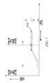
- FIG. 5is a method of charging a battery to a first energy stored level during a first time period 504 and charging the battery during a second time period 506 , according to one embodiment of the present subject matter. Illustrated is an example in which a battery is charged until the first energy stored level 502 is reached. In various embodiments, this charging is limited to a first time period 504 . In various examples, the first time period is coincident with the time of day in that a first charging cost rate is within in a first cost range.
- Additional embodimentscharge the battery until the second energy stored level 508 is reached. In various examples, this occurs during a second time period 506 .
- the second time period 506is user selected.
- the second time period 506is coincident with a period of time in which a charging cost rate fits into a second cost range that is different from a first cost range.
- the second energy stored level 508is less than a full energy stored level. The illustrated embodiment shows that the electric vehicle was unplugged shortly before it reached the second energy stored level 508 . This may be exhibited in examples in which a user decides to leave before the second time period ends.
- FIG. 6is a method of charging a battery during a second time period, according to one embodiment of the present subject matter.
- Embodiments of the present subject matterinclude charging the battery to the second energy stored level only if so instructed by a stored indicator, as discussed above.
- Some examplesinclude predicting a daily charge stop time 602 based on an energy usage pattern. Some instances prompt a user to select between improved calendar life and reduced cost. Embodiments that prompt a user for information include storing a user response as the stored indicator. In various examples, if the stored indicator indicates improved calendar life, the method charges to the second energy level by delaying charging to the second energy level until charging can occur constantly up to the predicted daily charge stop time such that the second energy stored level is reached.
- the present illustrationshows that the battery of an electric vehicle was already charged near a regular stored charge, and elected to not charge the battery during the first time period.
- the electric vehicle charging systemadditionally recognized a charge stop time, and commenced charging such that it could reach the second energy stored level 604 at the charge stop time 602 . Such a system can improve calendar life of a battery.
- Various embodimentsinclude electing to not charge to the second energy stored level.
- FIG. 7is a method of charging to a first energy stored 710 level during a first time period, and to a second energy stored 712 level during a second time period, according to one embodiment of the present subject matter.
- Various embodimentsinclude charging the battery according to a charging schedule that includes a first time period 702 and a second time period 704 , the first energy stored level 710 reached (during the ⁇ time period) within the first time period 702 , the second energy stored level 712 (during the ⁇ time period) reached during the second time period 704 .
- Some examplesinclude predicting a daily cost based on an energy usage pattern. Some instances adjust the length of the first time period and length of the second time period such that a total cost of charging to the second energy stored level is less than the predicted daily cost.
- Some examplesinclude predicting a daily charge stop time 706 based on an energy usage pattern. Some of these examples include delaying (during the ⁇ time period) charging to the second energy level until charging can occur constantly up to the predicted daily charge stop time 706 . In some instances, this occurs such that the second energy stored level 712 is reached. Embodiments are included in which no charging occurs during at least a portion of the second time period 704 .
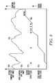
- FIG. 8is a method of charging a battery in the context of a charging rate that varies up and down throughout the day, according to one embodiment of the present subject matter.
- a charge rate 802is determined and varies.
- a battery energy stored level 804is charted in the illustration.
- the charging rateis at a first charge cost rate 806
- the batterycharges on its way to a first energy stored level 810 .
- the systemstops charging if it is during the first time period.
- a first time perioddefined by the addition of time periods ⁇ , ⁇ , and ⁇ is illustrated. During this time, the system charges only when the charging cost rate is within the first charging cost rate range 806 .
- the illustrationStarting after time period ⁇ , the illustration enters a second time period in which it is acceptable to charge as the second charging cost rate range 808 .
- the illustrationreaches a second stored energy level 812 , and does not add more charge during the ⁇ time period, during that the second charging cost rate is realized, nor after that time period, during which the first charging cost rate is realized.
- Various examplesinclude receiving a cost signal and charging at one of the first charging cost rate and the second charging cost rate in response to that cost signal.
- FIG. 9is a method according to one embodiment of the present subject matter.
- the methodincludes storing a user selected driving range for an electric vehicle.
- the methodincludes determining a potential driving range based on a pattern of driving ranges achieved by charging a battery of the electric vehicle to a first percentage of capacity.
- the methodincludes determining whether a first amount of energy stored when the battery is charged to the first percentage of capacity is sufficient to achieve the user selected driving range based on the pattern of driving ranges achieved.
- the methodincludes charging the battery to the first percentage of capacity if the first amount energy stored is sufficient to power the electric vehicle through the selected driving range.
- the methodincludes charging the battery to a second percentage of capacity, which is higher than the first percentage of capacity, if the first energy stored is not sufficient to power the electric vehicle through the user selected driving range. In certain examples, the second energy stored level is 100%.
- FIG. 10is a method of charging a battery to achieve a selected range, according to one embodiment of the present subject matter.
- a life cycle of a battery always charged to a regular capacity 1002is illustrated, with a regular end of life 1010 . This is the energy stored when the battery is charged to a specific capacity, such as 80%, that is less than full capacity. Additionally illustrated is a life cycle of a battery always charged to a full capacity 1004 , with a full end of life 1006 .
- a hybrid curve 1012is illustrated for a battery which is at first charged to a regular capacity, and then to a capacity that is more than the regular capacity, demonstrating a hybrid end of life 1008 .
- the hybridbegins to charge a battery at a capacity higher than a regular capacity starting at a certain time 1014 , although the present subject matter is not so limited.
- the time hybrid starts to charge to a capacity in excess of the regular capacity commencescan coincide with the time that energy stored when charged to regular capacity starts to diminish.
- the penalty for charging the hybrid higher than the regular capacityis an earlier end of life 1008 than the end of life 1010 enjoyed by batteries always charged to regular capacity.
- Battery capacityhas a linear relationship with voltage in some examples, and certain instances charge to respective voltages in certain examples.
- the hybrid curveassists in a user to consistently maintain a usable driving range. For example, if energy stored for a certain capacity starts to diminish, as it does for the regular capacity curve 1002 after a certain time 1014 , driving range for that capacity also diminishes. But some users desire to avoid diminished range. As such, the present subject matter charges to a higher capacity, following the hybrid curve 1012 . This provides a compromise between enjoying some time during which a longer range is realized, and shortening the end of life of the battery.
- Various examples of the present subject matterautomatically track decreasing range based on an energy use pattern. Some of these embodiments switch to a hybrid curve automatically, so a user does not realize range is decreasing. In some embodiments, switching to the hybrid curve occurs only if the end of life is predicted to occur within the warranty period of an electric vehicle. Some embodiments provide an alert to a user than charging to a hybrid capacity has begun. In some instances the hybrid curve includes a series of incremental upward adjustments to capacity. In some embodiments, capacity is increased by 0.05% a day. Other increases are contemplated.
- a vehicle systemdrives a first range during some driving sessions and a second range during additional driving sessions, and a user selects which range to drive.
- a vehicle charging systemautomatically selects which of the regular capacity and the hybrid capacity to use depending on the user selected range.
Landscapes
- Engineering & Computer Science (AREA)
- Power Engineering (AREA)
- Business, Economics & Management (AREA)
- Transportation (AREA)
- Mechanical Engineering (AREA)
- Economics (AREA)
- Development Economics (AREA)
- Strategic Management (AREA)
- Marketing (AREA)
- Physics & Mathematics (AREA)
- Finance (AREA)
- Accounting & Taxation (AREA)
- Theoretical Computer Science (AREA)
- General Physics & Mathematics (AREA)
- Health & Medical Sciences (AREA)
- General Business, Economics & Management (AREA)
- Life Sciences & Earth Sciences (AREA)
- Water Supply & Treatment (AREA)
- Sustainable Energy (AREA)
- Primary Health Care (AREA)
- Human Resources & Organizations (AREA)
- General Health & Medical Sciences (AREA)
- Sustainable Development (AREA)
- Tourism & Hospitality (AREA)
- Entrepreneurship & Innovation (AREA)
- Public Health (AREA)
- Game Theory and Decision Science (AREA)
- Charge And Discharge Circuits For Batteries Or The Like (AREA)
- Electric Propulsion And Braking For Vehicles (AREA)
- Secondary Cells (AREA)
Abstract
Description
Claims (22)
Priority Applications (8)
| Application Number | Priority Date | Filing Date | Title |
|---|---|---|---|
| US11/779,837US7782021B2 (en) | 2007-07-18 | 2007-07-18 | Battery charging based on cost and life |
| AU2008276398AAU2008276398B2 (en) | 2007-07-18 | 2008-06-20 | Battery charging based on cost and life |
| PCT/US2008/067670WO2009012018A2 (en) | 2007-07-18 | 2008-06-20 | Battery charging based on cost and life |
| CN200880107602XACN101821121B (en) | 2007-07-18 | 2008-06-20 | Battery charging based on cost and life |
| EP08771593.4AEP2183125B8 (en) | 2007-07-18 | 2008-06-20 | Battery charging based on cost and life |
| JP2010517051AJP5088976B2 (en) | 2007-07-18 | 2008-06-20 | Battery charging based on cost and lifetime |
| US12/434,041US7786704B2 (en) | 2007-07-18 | 2009-05-01 | System for battery charging based on cost and life |
| US12/434,067US7719232B2 (en) | 2007-07-18 | 2009-05-01 | Method for battery charging based on cost and life |
Applications Claiming Priority (1)
| Application Number | Priority Date | Filing Date | Title |
|---|---|---|---|
| US11/779,837US7782021B2 (en) | 2007-07-18 | 2007-07-18 | Battery charging based on cost and life |
Related Child Applications (2)
| Application Number | Title | Priority Date | Filing Date |
|---|---|---|---|
| US12/434,067DivisionUS7719232B2 (en) | 2007-07-18 | 2009-05-01 | Method for battery charging based on cost and life |
| US12/434,041DivisionUS7786704B2 (en) | 2007-07-18 | 2009-05-01 | System for battery charging based on cost and life |
Publications (2)
| Publication Number | Publication Date |
|---|---|
| US20090021218A1 US20090021218A1 (en) | 2009-01-22 |
| US7782021B2true US7782021B2 (en) | 2010-08-24 |
Family
ID=39735302
Family Applications (3)
| Application Number | Title | Priority Date | Filing Date |
|---|---|---|---|
| US11/779,837Active2027-12-28US7782021B2 (en) | 2007-07-18 | 2007-07-18 | Battery charging based on cost and life |
| US12/434,067ActiveUS7719232B2 (en) | 2007-07-18 | 2009-05-01 | Method for battery charging based on cost and life |
| US12/434,041ActiveUS7786704B2 (en) | 2007-07-18 | 2009-05-01 | System for battery charging based on cost and life |
Family Applications After (2)
| Application Number | Title | Priority Date | Filing Date |
|---|---|---|---|
| US12/434,067ActiveUS7719232B2 (en) | 2007-07-18 | 2009-05-01 | Method for battery charging based on cost and life |
| US12/434,041ActiveUS7786704B2 (en) | 2007-07-18 | 2009-05-01 | System for battery charging based on cost and life |
Country Status (6)
| Country | Link |
|---|---|
| US (3) | US7782021B2 (en) |
| EP (1) | EP2183125B8 (en) |
| JP (1) | JP5088976B2 (en) |
| CN (1) | CN101821121B (en) |
| AU (1) | AU2008276398B2 (en) |
| WO (1) | WO2009012018A2 (en) |
Cited By (30)
| Publication number | Priority date | Publication date | Assignee | Title |
|---|---|---|---|---|
| US20100017043A1 (en)* | 2007-09-05 | 2010-01-21 | Consolidated Edison Company Of New York, Inc. | Hybrid vehicle recharging system and method of operation |
| US20100100342A1 (en)* | 2007-09-05 | 2010-04-22 | Consolidated Edison Company Of New York, Inc. | Metering system and method of operation |
| US20110178959A1 (en)* | 2010-01-19 | 2011-07-21 | Kabushiki Kaisha Toshiba | Charge and discharge control device |
| US8154246B1 (en)* | 2009-01-30 | 2012-04-10 | Comverge, Inc. | Method and system for charging of electric vehicles according to user defined prices and price off-sets |
| WO2013006229A1 (en)* | 2011-07-01 | 2013-01-10 | Honda Motor Co., Ltd. | Electric vehicle charging strategy |
| US20130082517A1 (en)* | 2011-09-29 | 2013-04-04 | Kobelco Cranes Co., Ltd. | Operating machine |
| US8595122B2 (en) | 2010-07-23 | 2013-11-26 | Electric Transportation Engineering Corporation | System for measuring electricity and method of providing and using the same |
| US8710372B2 (en) | 2010-07-23 | 2014-04-29 | Blink Acquisition, LLC | Device to facilitate moving an electrical cable of an electric vehicle charging station and method of providing the same |
| US8725330B2 (en) | 2010-06-02 | 2014-05-13 | Bryan Marc Failing | Increasing vehicle security |
| US8855832B2 (en) | 2012-04-17 | 2014-10-07 | Renewable Environmental Energy Service Inc. | Rate based power management device |
| US8963492B2 (en) | 2008-12-15 | 2015-02-24 | Comverge, Inc. | Method and system for co-operative charging of electric vehicles |
| US20150069970A1 (en)* | 2013-09-11 | 2015-03-12 | Proterra Inc. | Methods and systems for electric vehicle charging |
| US9348381B2 (en) | 2011-10-19 | 2016-05-24 | Zeco Systems Pte Ltd | Methods and apparatuses for charging of electric vehicles |
| US9457680B2 (en) | 2013-11-15 | 2016-10-04 | Honda Motor Co., Ltd. | Vehicle-to-grid control |
| US9637020B2 (en) | 2013-05-21 | 2017-05-02 | Tesla, Inc. | Location based charging control of electric vehicle |
| US9744873B2 (en) | 2011-10-12 | 2017-08-29 | Volkswagen Ag | Method and control device for charging a battery of a vehicle |
| US20180194238A1 (en)* | 2017-01-10 | 2018-07-12 | Toyota Jidosha Kabushiki Kaisha | Charge controller and charge control method |
| US10140670B2 (en) | 2012-08-31 | 2018-11-27 | Engie Storage Services Na Llc | Energy management methods and systems based on financial impact |
| US10220718B2 (en) | 2017-04-07 | 2019-03-05 | Honda Motor Co., Ltd. | System and method for creating a charging schedule for an electric vehicle |
| US20190217716A1 (en)* | 2018-01-18 | 2019-07-18 | Ford Global Technologies, Llc | Smart charging battery systems and methods for electrified vehicles |
| US10442302B2 (en) | 2009-05-14 | 2019-10-15 | Battelle Memorial Institute | Battery charging control methods, electrical vehicle charging methods, battery charging control apparatus, and electrical vehicles |
| US10625625B2 (en) | 2017-04-07 | 2020-04-21 | Honda Motor Co., Ltd. | System and method for creating a charging schedule for an electric vehicle |
| US10658841B2 (en) | 2017-07-14 | 2020-05-19 | Engie Storage Services Na Llc | Clustered power generator architecture |
| US10999652B2 (en) | 2017-05-24 | 2021-05-04 | Engie Storage Services Na Llc | Energy-based curtailment systems and methods |
| US20220097558A1 (en)* | 2020-09-28 | 2022-03-31 | Hyundai Mobis Co., Ltd. | Communication method between electric vehicle, supply equipment and power grid operation server |
| US20220097551A1 (en)* | 2020-09-28 | 2022-03-31 | Hyundai Mobis Co., Ltd. | Communication method between electric vehicle, supply equipment and power grid operation server |
| US11336107B2 (en)* | 2016-07-13 | 2022-05-17 | Sony Corporation | Information processing device, information processing system, and charging method |
| US20220200066A1 (en)* | 2008-08-18 | 2022-06-23 | Christopher B. Austin | Vehicular battery charger, charging system, and method with communication indicator |
| TWI774856B (en)* | 2017-10-17 | 2022-08-21 | 大陸商蔚來(安徽)控股有限公司 | Method and apparatus for determining a charging strategy for an under-charged battery in a swapping station |
| US11563338B1 (en) | 2008-07-11 | 2023-01-24 | Charge Fusion Technologies, Llc | Systems and methods for electric vehicle charging and power management |
Families Citing this family (93)
| Publication number | Priority date | Publication date | Assignee | Title |
|---|---|---|---|---|
| JP5228322B2 (en)* | 2006-08-30 | 2013-07-03 | トヨタ自動車株式会社 | Power storage device deterioration evaluation system, vehicle, power storage device deterioration evaluation method, and computer-readable recording medium storing a program for causing a computer to execute the deterioration evaluation method |
| US20080312782A1 (en)* | 2007-06-15 | 2008-12-18 | Gene Berdichevsky | Electric vehicle communication interface |
| US8978798B2 (en) | 2007-10-12 | 2015-03-17 | Odyne Systems, Llc | Hybrid vehicle drive system and method and idle reduction system and method |
| US20120207620A1 (en) | 2007-07-12 | 2012-08-16 | Odyne Systems, LLC. | Hybrid vehicle drive system and method and idle reduction system and method |
| US9061680B2 (en) | 2007-07-12 | 2015-06-23 | Odyne Systems, Llc | Hybrid vehicle drive system and method for fuel reduction during idle |
| US8408341B2 (en) | 2007-07-12 | 2013-04-02 | Odyne Systems, Llc | Hybrid vehicle drive system and method and idle reduction system and method |
| US7782021B2 (en)* | 2007-07-18 | 2010-08-24 | Tesla Motors, Inc. | Battery charging based on cost and life |
| JP5484686B2 (en)* | 2008-03-31 | 2014-05-07 | パナソニック株式会社 | Electronic device, charger, and electronic device charging system |
| JP4932810B2 (en)* | 2008-10-20 | 2012-05-16 | マツダ株式会社 | Method and apparatus for charging battery for electric vehicle |
| JP4572979B2 (en)* | 2008-10-21 | 2010-11-04 | トヨタ自動車株式会社 | Power supply system, vehicle equipped with the same, and control method of power supply system |
| CN102202930B (en)* | 2008-10-31 | 2014-01-01 | 丰田自动车株式会社 | Electric vehicle and control method for electric vehicle |
| US20100179893A1 (en)* | 2009-01-14 | 2010-07-15 | Tonya Marie Burke | System for controlling the charge rate of an electric vehicle battery by a third party, and monitoring, recording, and reporting the power supplied to it. |
| US8054038B2 (en)* | 2009-01-29 | 2011-11-08 | Tesla Motors, Inc. | System for optimizing battery pack cut-off voltage |
| US9409533B2 (en)* | 2009-05-11 | 2016-08-09 | Mahindra Reva Electric Vehicles Pvt. Ltd. | System and method for monitoring and controlling energy system |
| WO2010141229A2 (en)* | 2009-06-01 | 2010-12-09 | Edward Mcintyre | Electrical power metering and billing network |
| DE102009025132A1 (en)* | 2009-06-17 | 2010-12-23 | Bayerische Motoren Werke Aktiengesellschaft | Energy storage charging system |
| WO2011009129A1 (en)* | 2009-07-17 | 2011-01-20 | Gridpoint, Inc. | System and methods for smart charging techniques, values and guarantees |
| US8922329B2 (en) | 2009-07-23 | 2014-12-30 | Qualcomm Incorporated | Battery charging to extend battery life and improve efficiency |
| RU2522425C2 (en)* | 2009-08-11 | 2014-07-10 | Сони Корпорейшн | Electronic device, electronic device charging method, computer programme, charge control apparatus and charge control method |
| US20110047102A1 (en)* | 2009-08-18 | 2011-02-24 | Ford Global Technologies, Llc | Vehicle battery charging system and method |
| DE112010003507T5 (en)* | 2009-09-01 | 2012-07-26 | Sony Corporation | Method and system for data exchange between a vehicle and a server |
| US8473131B2 (en)* | 2009-09-28 | 2013-06-25 | Powerhydrant Llc | Method and system for charging electric vehicles |
| DE102009045784A1 (en)* | 2009-10-19 | 2011-04-21 | Robert Bosch Gmbh | Method and charging control to increase the life of accumulators |
| JP4881991B2 (en)* | 2009-10-26 | 2012-02-22 | 本田技研工業株式会社 | Electric vehicle oil temperature rise control method and apparatus, and electric vehicle |
| US9299093B2 (en)* | 2010-01-29 | 2016-03-29 | GM Global Technology Operations LLC | Method for charging a plug-in electric vehicle |
| US8093861B2 (en) | 2010-02-21 | 2012-01-10 | Greenwave Reality, Pte Ltd. | Power transfer system for a rechargeable battery |
| EP2537229A2 (en)* | 2010-02-21 | 2012-12-26 | Greenwave Reality Pte Ltd | Power transfer system for a rechargeable battery |
| US8853999B2 (en) | 2010-04-19 | 2014-10-07 | Interim Designs Inc. | Automated electric vehicle charging system and method |
| US8169186B1 (en)* | 2010-04-19 | 2012-05-01 | Interim Designs Inc. | Automated electric vehicle charging system and method |
| KR101132948B1 (en)* | 2010-05-13 | 2012-04-05 | 엘에스산전 주식회사 | System, Apparatus and Method for Charge and Discharge Control of Electric Vehicle |
| US8359132B2 (en)* | 2010-06-16 | 2013-01-22 | Toyota Motor Engineering & Manufacturing North America, Inc. | System and method for optimizing use of a battery |
| DE102010030309A1 (en) | 2010-06-21 | 2011-12-22 | Ford Global Technologies, Llc | Method and device for determining an energy consumption optimized route |
| US8718844B2 (en)* | 2010-07-19 | 2014-05-06 | General Motors Llc | Charge notification method for extended range electric vehicles |
| WO2012017936A1 (en)* | 2010-08-05 | 2012-02-09 | 三菱自動車工業株式会社 | Battery information output device for power supply/demand leveling system |
| JP2012039725A (en)* | 2010-08-05 | 2012-02-23 | Toyota Motor Corp | Charging method and charging system |
| JP2012044822A (en)* | 2010-08-23 | 2012-03-01 | Sanyo Electric Co Ltd | Charging system |
| DE102010040395A1 (en)* | 2010-09-08 | 2012-03-08 | Siemens Aktiengesellschaft | Method and device for efficiently charging a vehicle battery |
| JP5510259B2 (en)* | 2010-10-07 | 2014-06-04 | 株式会社デンソー | Vehicle power control device |
| US20110225105A1 (en)* | 2010-10-21 | 2011-09-15 | Ford Global Technologies, Llc | Method and system for monitoring an energy storage system for a vehicle for trip planning |
| WO2012066934A1 (en)* | 2010-11-15 | 2012-05-24 | 三菱自動車工業株式会社 | Charging control device for electric vehicle |
| CN102044723B (en)* | 2010-11-25 | 2013-01-30 | 奇瑞汽车股份有限公司 | Intelligent charging method for electromobile |
| EP2458704A1 (en)* | 2010-11-30 | 2012-05-30 | Restore N.V. | Method and system for charging a fleet of batteries |
| JP5506052B2 (en)* | 2010-12-28 | 2014-05-28 | トヨタ自動車株式会社 | Vehicle charging device |
| US8606444B2 (en)* | 2010-12-29 | 2013-12-10 | Caterpillar Inc. | Machine and power system with electrical energy storage device |
| US8849499B2 (en)* | 2011-01-06 | 2014-09-30 | Ford Global Technologies, Llc | Methods and systems for monitoring a vehicle's energy source |
| US20110224852A1 (en)* | 2011-01-06 | 2011-09-15 | Ford Global Technologies, Llc | Methods and system for selectively charging a vehicle |
| US8810208B2 (en) | 2011-03-10 | 2014-08-19 | Tesla Motors, Inc. | Charging efficiency using selectable isolation |
| JP5982736B2 (en)* | 2011-03-30 | 2016-08-31 | ソニー株式会社 | Power storage device, power storage method and program |
| US8928273B2 (en)* | 2011-04-08 | 2015-01-06 | Go-Tech Energy Co. Ltd. | Display device for displaying information of rechargeable battery of electric vehicle and charging module having the display device |
| US9225197B2 (en) | 2011-05-06 | 2015-12-29 | Tesla Motors, Inc. | Charging efficiency using variable isolation |
| DE102011102423A1 (en) | 2011-05-24 | 2012-11-29 | Audi Ag | Method for operating a motor vehicle |
| US8854013B2 (en)* | 2011-07-27 | 2014-10-07 | The Boeing Company | System for monitoring a battery charger |
| US20130041552A1 (en) | 2011-08-11 | 2013-02-14 | Ford Global Technologies, Llc | Methods and Apparatus for Estimating Power Usage |
| FR2979762B1 (en)* | 2011-09-07 | 2015-04-10 | Electricite De France | METHOD AND DEVICE FOR OPTIMIZED RECHARGING OF ELECTRIC BATTERY |
| US8907776B2 (en)* | 2011-10-05 | 2014-12-09 | Ford Global Technologies, Llc | Method and apparatus for do not disturb message delivery |
| CN103875148B (en)* | 2011-10-07 | 2017-07-11 | 丰田自动车株式会社 | The charging system of vehicle and the charging method of vehicle |
| EP2785570B1 (en)* | 2011-12-02 | 2022-09-14 | Power Technology Holdings, LLC | System for and method of fuel optimization in a hybrid vehicle |
| US12330657B2 (en) | 2011-12-02 | 2025-06-17 | Power Technology Holdings Llc | Hybrid vehicle drive system and method for fuel reduction during idle |
| US11225240B2 (en) | 2011-12-02 | 2022-01-18 | Power Technology Holdings, Llc | Hybrid vehicle drive system and method for fuel reduction during idle |
| US8849742B2 (en) | 2012-01-24 | 2014-09-30 | Ford Global Technologies, Llc | Method and apparatus for providing charging state alerts |
| KR101475564B1 (en)* | 2012-04-25 | 2014-12-30 | 엘에스산전 주식회사 | An electric vehicle charging system and method for charging electric vehicle |
| FR2992779B1 (en)* | 2012-06-29 | 2014-06-13 | Renault Sa | METHOD AND DEVICES FOR MAXIMIZING THE LIFETIME OF A TRACTION BATTERY OF AN ELECTRIC VEHICLE, IN PARTICULAR A LI-ION BATTERY |
| US9783140B2 (en)* | 2012-09-14 | 2017-10-10 | Ford Global Technologies, Llc | Method and apparatus for remote fuel refill level monitoring |
| US9537339B2 (en)* | 2012-09-28 | 2017-01-03 | Henry Shum | High-efficiency battery charger |
| US9128159B2 (en)* | 2012-12-12 | 2015-09-08 | GM Global Technology Operations LLC | Plug-in charge capacity estimation method for lithium iron-phosphate batteries |
| JP6088858B2 (en)* | 2013-03-12 | 2017-03-01 | シャープ株式会社 | Self-propelled equipment |
| US9462545B2 (en) | 2013-03-14 | 2016-10-04 | Ford Global Technologies, Llc | Method and apparatus for a battery saver utilizing a sleep and vacation strategy |
| US9066298B2 (en) | 2013-03-15 | 2015-06-23 | Ford Global Technologies, Llc | Method and apparatus for an alert strategy between modules |
| US9493087B2 (en) | 2013-08-07 | 2016-11-15 | Powerhydrant Llc | Method and system for automatic charging of electric vehicles |
| EP3054552B1 (en)* | 2013-09-30 | 2020-03-18 | Korea Electric Power Corporation | Apparatus and method for economically charging electronic vehicle |
| CN106061784B (en) | 2013-11-18 | 2019-07-19 | 电力科技控股有限责任公司 | Hybrid vehicle drive system and method using split shaft PTO |
| KR101551011B1 (en)* | 2013-12-18 | 2015-09-07 | 현대자동차주식회사 | Charging method of green car |
| US9488493B2 (en) | 2014-01-16 | 2016-11-08 | Ford Global Technologies, Llc | Method and apparatus for electric vehicle trip and recharge planning |
| EP3102457A4 (en)* | 2014-02-07 | 2018-02-14 | Recargo, Inc. | Presenting routing information for electric vehicles |
| FR3018008A1 (en)* | 2014-02-21 | 2015-08-28 | Orange | DEVICE FOR SUPPLYING AN ELECTRICAL APPARATUS |
| US10552923B2 (en)* | 2014-05-08 | 2020-02-04 | Honda Motor Co., Ltd. | Electric vehicle charging control system |
| FR3036342B1 (en)* | 2015-05-22 | 2017-06-16 | Dassault Aviat | RETRACTABLE SUPPORT FOR SCREEN, AND ARRANGEMENT FOR INTERIOR INSTALLATION OF AN AIRCRAFT CAR INCLUDING A SUPPORT |
| CN107614313A (en)* | 2015-06-10 | 2018-01-19 | 沃尔沃卡车集团 | For the method and system in the life-span for optimizing energy storage system |
| US10044213B2 (en) | 2015-09-09 | 2018-08-07 | Texas Instruments Incorporated | Fast charging for lithium ion battery |
| DE112016006782T5 (en)* | 2016-05-25 | 2019-01-24 | Ford Global Technologies, Llc | Methods and devices for charging electric vehicles |
| JP6234526B1 (en)* | 2016-09-20 | 2017-11-22 | 本田技研工業株式会社 | Transaction management system, transaction management method and program |
| US10128668B2 (en) | 2016-09-30 | 2018-11-13 | Sears Brands, L.L.C. | Charger, charge indicator, and associated methods |
| DE102017209489A1 (en)* | 2017-06-06 | 2018-12-06 | Robert Bosch Gmbh | Method and charging unit for charging an electrical energy store |
| EP3425762A1 (en)* | 2017-07-03 | 2019-01-09 | Ningbo Geely Automobile Research & Development Co. Ltd. | Method and electronic device for managing charging |
| CN109038751B (en)* | 2018-08-22 | 2022-03-25 | 惠州Tcl移动通信有限公司 | Charging control method, mobile terminal and storage medium |
| CN109256835B (en)* | 2018-10-16 | 2022-03-18 | 深圳壹账通智能科技有限公司 | Charging control method of mobile terminal, storage medium and mobile terminal |
| FR3091788B1 (en)* | 2019-01-10 | 2023-09-22 | Renault Sas | Method of charging a storage battery using a charging terminal |
| US10998730B1 (en) | 2019-04-26 | 2021-05-04 | NeoVolta, Inc. | Adaptive solar power battery storage system |
| US20210281092A1 (en)* | 2020-03-09 | 2021-09-09 | Medtronic Minimed, Inc. | Networked dynamic management of charge |
| US12008848B2 (en) | 2021-09-22 | 2024-06-11 | Garrett Transportation I Inc. | Adaptive fuel and charge consumption estimation in powertrain systems |
| KR20230123840A (en)* | 2022-02-17 | 2023-08-24 | 주식회사 엘지에너지솔루션 | Apparatus for managing battery and server |
| US12253568B2 (en)* | 2022-05-06 | 2025-03-18 | Ford Global Technologies, Llc | Charge time estimating method and system |
| CN115742781B (en)* | 2022-11-24 | 2025-02-14 | 北京胜能能源科技有限公司 | A battery charging method, device, electronic device and storage medium thereof |
Citations (25)
| Publication number | Priority date | Publication date | Assignee | Title |
|---|---|---|---|---|
| US5467006A (en)* | 1992-12-21 | 1995-11-14 | Ford Motor Company | Energy transfer device and method |
| US5650710A (en) | 1995-02-06 | 1997-07-22 | Honda Giken Kogyo Kabushiki Kaisha | Apparatus for controlling a charging start time and charging period for a storage battery in an electric vehicle to complete charging at a scheduled boarding time |
| US5892346A (en) | 1995-02-27 | 1999-04-06 | Kabushikikaisha Equos Research | Vehicle |
| US6011380A (en) | 1999-03-31 | 2000-01-04 | Honda Giken Kogyo Kabushiki Kaisha | Refreshing charge control method and apparatus to extend the life of batteries |
| US6166449A (en) | 1996-09-17 | 2000-12-26 | Toyota Jidosha Kabushiki Kaisha | Power output apparatus having a battery with a high charge-discharge efficiency |
| US6335610B1 (en) | 2000-06-30 | 2002-01-01 | Ford Global Technologies, Inc. | Method and apparatus for determining the operational energy cost of a hybrid vehicle |
| US6545449B2 (en) | 2001-04-10 | 2003-04-08 | Matsushita Electric Industrial Co., Ltd. | Method for controlling charge to secondary battery for automated guided vehicle |
| US6674265B2 (en) | 2001-03-28 | 2004-01-06 | Japan Storage Battery Co., Ltd. | Operation method for secondary battery and secondary battery device |
| US20040074682A1 (en) | 2000-11-23 | 2004-04-22 | Fussey Peter Michael | Hybrid powder sources distribution management |
| US20040164616A1 (en) | 2003-02-25 | 2004-08-26 | Denso Corporation | Method for controlling vehicular electric system |
| US20050127855A1 (en) | 2002-01-24 | 2005-06-16 | Aloys Wobben | Vehicle |
| US20050237029A1 (en) | 2004-04-22 | 2005-10-27 | Matsushita Electric Industrial Co.,Ltd. | Charger for lithium secondary battery and electronic apparatus including charger |
| US7013205B1 (en) | 2004-11-22 | 2006-03-14 | International Business Machines Corporation | System and method for minimizing energy consumption in hybrid vehicles |
| US20060142915A1 (en) | 2003-07-17 | 2006-06-29 | Toyota Jidosha Kabushiki Kaisha | Moving body energy management apparatus and moving body energy management method |
| US20070029121A1 (en) | 2004-01-16 | 2007-02-08 | Mikio Saitou | Hybrid vehicle |
| US20080027639A1 (en) | 2004-03-30 | 2008-01-31 | Williams International Co., L.L.C. | Method of anticipating a vehicle destination |
| US7345452B2 (en) | 2004-12-21 | 2008-03-18 | Hyundai Motor Company | Method of calculating SOC of battery for prevention of memory effect |
| US20080084186A1 (en) | 2006-10-02 | 2008-04-10 | Ford Global Technologies Llc | System and method for controlling a state of charge of an energy storage system |
| US20080150490A1 (en) | 2006-12-22 | 2008-06-26 | Christopher Richard Koziara | Controlling state of charge of a vehicle battery |
| US20080203973A1 (en)* | 2007-02-27 | 2008-08-28 | Gale Allan R | Interactive battery charger for electric vehicle |
| US20080288132A1 (en) | 2007-05-16 | 2008-11-20 | General Electric Company | Method of operating vehicle and associated system |
| WO2009012018A2 (en) | 2007-07-18 | 2009-01-22 | Tesla Motors, Inc. | Battery charging based on cost and life |
| US20090062967A1 (en) | 2007-09-05 | 2009-03-05 | Consolidated Edison Company Of New York, Inc. | Hybrid vehicle recharging system and method of operation |
| US20090093999A1 (en) | 2007-10-04 | 2009-04-09 | Boeing Company, A Corporation Of Delaware | Method and system for quantifying damage in a structure |
| US20090277702A1 (en) | 2005-10-07 | 2009-11-12 | Toyota Jidosha Kabushiki Kaisha | Hybrid vehicle and method of controlling the same |
Family Cites Families (9)
| Publication number | Priority date | Publication date | Assignee | Title |
|---|---|---|---|---|
| JP2785316B2 (en)* | 1989-04-19 | 1998-08-13 | 株式会社豊田自動織機製作所 | Charger |
| JPH0630532A (en)* | 1992-07-08 | 1994-02-04 | Toyota Autom Loom Works Ltd | Charger |
| JPH07161384A (en)* | 1993-12-07 | 1995-06-23 | Kojima Press Co Ltd | Charging method of electric vehicle |
| JPH07250405A (en)* | 1994-03-11 | 1995-09-26 | Fujitsu Denso Ltd | Charger for electric automobile |
| JP3712518B2 (en)* | 1998-01-26 | 2005-11-02 | 株式会社アイチコーポレーション | Battery charger |
| KR100326704B1 (en)* | 1999-07-08 | 2002-03-12 | 이계안 | A battery charging device and a method thereof for electric car |
| JP2002095174A (en)* | 2000-09-13 | 2002-03-29 | Casio Comput Co Ltd | Power supply device and charge / discharge method thereof |
| JP2002142378A (en)* | 2000-10-31 | 2002-05-17 | Canon Inc | Charging device, method and storage medium |
| US8664915B2 (en)* | 2006-12-06 | 2014-03-04 | Marvell World Trade Ltd. | Plug-in vehicle |
- 2007
- 2007-07-18USUS11/779,837patent/US7782021B2/enactiveActive
- 2008
- 2008-06-20JPJP2010517051Apatent/JP5088976B2/enactiveActive
- 2008-06-20EPEP08771593.4Apatent/EP2183125B8/enactiveActive
- 2008-06-20CNCN200880107602XApatent/CN101821121B/enactiveActive
- 2008-06-20AUAU2008276398Apatent/AU2008276398B2/enactiveActive
- 2008-06-20WOPCT/US2008/067670patent/WO2009012018A2/enactiveApplication Filing
- 2009
- 2009-05-01USUS12/434,067patent/US7719232B2/enactiveActive
- 2009-05-01USUS12/434,041patent/US7786704B2/enactiveActive
Patent Citations (28)
| Publication number | Priority date | Publication date | Assignee | Title |
|---|---|---|---|---|
| US5467006A (en)* | 1992-12-21 | 1995-11-14 | Ford Motor Company | Energy transfer device and method |
| US5650710A (en) | 1995-02-06 | 1997-07-22 | Honda Giken Kogyo Kabushiki Kaisha | Apparatus for controlling a charging start time and charging period for a storage battery in an electric vehicle to complete charging at a scheduled boarding time |
| US5892346A (en) | 1995-02-27 | 1999-04-06 | Kabushikikaisha Equos Research | Vehicle |
| US6166449A (en) | 1996-09-17 | 2000-12-26 | Toyota Jidosha Kabushiki Kaisha | Power output apparatus having a battery with a high charge-discharge efficiency |
| US6011380A (en) | 1999-03-31 | 2000-01-04 | Honda Giken Kogyo Kabushiki Kaisha | Refreshing charge control method and apparatus to extend the life of batteries |
| US6335610B1 (en) | 2000-06-30 | 2002-01-01 | Ford Global Technologies, Inc. | Method and apparatus for determining the operational energy cost of a hybrid vehicle |
| US20040074682A1 (en) | 2000-11-23 | 2004-04-22 | Fussey Peter Michael | Hybrid powder sources distribution management |
| US6674265B2 (en) | 2001-03-28 | 2004-01-06 | Japan Storage Battery Co., Ltd. | Operation method for secondary battery and secondary battery device |
| US6545449B2 (en) | 2001-04-10 | 2003-04-08 | Matsushita Electric Industrial Co., Ltd. | Method for controlling charge to secondary battery for automated guided vehicle |
| US20050127855A1 (en) | 2002-01-24 | 2005-06-16 | Aloys Wobben | Vehicle |
| US20040164616A1 (en) | 2003-02-25 | 2004-08-26 | Denso Corporation | Method for controlling vehicular electric system |
| US20060142915A1 (en) | 2003-07-17 | 2006-06-29 | Toyota Jidosha Kabushiki Kaisha | Moving body energy management apparatus and moving body energy management method |
| US20070029121A1 (en) | 2004-01-16 | 2007-02-08 | Mikio Saitou | Hybrid vehicle |
| US20080027639A1 (en) | 2004-03-30 | 2008-01-31 | Williams International Co., L.L.C. | Method of anticipating a vehicle destination |
| US20050237029A1 (en) | 2004-04-22 | 2005-10-27 | Matsushita Electric Industrial Co.,Ltd. | Charger for lithium secondary battery and electronic apparatus including charger |
| US7013205B1 (en) | 2004-11-22 | 2006-03-14 | International Business Machines Corporation | System and method for minimizing energy consumption in hybrid vehicles |
| US7345452B2 (en) | 2004-12-21 | 2008-03-18 | Hyundai Motor Company | Method of calculating SOC of battery for prevention of memory effect |
| US20090277702A1 (en) | 2005-10-07 | 2009-11-12 | Toyota Jidosha Kabushiki Kaisha | Hybrid vehicle and method of controlling the same |
| US20080084186A1 (en) | 2006-10-02 | 2008-04-10 | Ford Global Technologies Llc | System and method for controlling a state of charge of an energy storage system |
| US20080150490A1 (en) | 2006-12-22 | 2008-06-26 | Christopher Richard Koziara | Controlling state of charge of a vehicle battery |
| US20080203973A1 (en)* | 2007-02-27 | 2008-08-28 | Gale Allan R | Interactive battery charger for electric vehicle |
| US20080288132A1 (en) | 2007-05-16 | 2008-11-20 | General Electric Company | Method of operating vehicle and associated system |
| WO2009012018A2 (en) | 2007-07-18 | 2009-01-22 | Tesla Motors, Inc. | Battery charging based on cost and life |
| WO2009012018A3 (en) | 2007-07-18 | 2009-05-14 | Tesla Motors Inc | Battery charging based on cost and life |
| US20090216688A1 (en) | 2007-07-18 | 2009-08-27 | Tesla Motors, Inc. | System for battery charging based on cost and life |
| US20090212745A1 (en) | 2007-07-18 | 2009-08-27 | Tesla Motors, Inc. | Method for battery charging based on cost and life |
| US20090062967A1 (en) | 2007-09-05 | 2009-03-05 | Consolidated Edison Company Of New York, Inc. | Hybrid vehicle recharging system and method of operation |
| US20090093999A1 (en) | 2007-10-04 | 2009-04-09 | Boeing Company, A Corporation Of Delaware | Method and system for quantifying damage in a structure |
Non-Patent Citations (4)
| Title |
|---|
| "International Application Serial No. PCT/US2008/067670, International Search Report mailed Mar. 25, 2009". |
| "International Application Serial No. PCT/US2008/067670, Written Opinion mailed Mar. 25, 2009". |
| "U.S. Appl. No. 12/434,067 , Notice of Allowance mailed Jan. 6, 2010", 12 Pgs. |
| International Application Serial No. PCT/US2008/067670, Invitation to Pay Additional Fees and Partial Search Report mailed Oct. 23, 2008, 8 pgs. |
Cited By (96)
| Publication number | Priority date | Publication date | Assignee | Title |
|---|---|---|---|---|
| US20100023178A1 (en)* | 2007-09-05 | 2010-01-28 | Consolidated Edison Company Of New York, Inc. | Hybrid vehicle recharging system and method of operation |
| US20100100342A1 (en)* | 2007-09-05 | 2010-04-22 | Consolidated Edison Company Of New York, Inc. | Metering system and method of operation |
| US20100256830A1 (en)* | 2007-09-05 | 2010-10-07 | Consolidated Edison Company Of New York, Inc. | Hybrid vehicle recharging system and method of operation |
| US20110153131A1 (en)* | 2007-09-05 | 2011-06-23 | Consolidated Edison Company Of New York, Inc. | Metering system and method of operation |
| US8100206B2 (en) | 2007-09-05 | 2012-01-24 | Consolidated Edison Company Of New York, Inc. | Hybrid vehicle recharging system and method of operation |
| US8170699B2 (en) | 2007-09-05 | 2012-05-01 | Consolidated Edison Company Of New York, Inc. | Metering system and method of operation |
| US20100017043A1 (en)* | 2007-09-05 | 2010-01-21 | Consolidated Edison Company Of New York, Inc. | Hybrid vehicle recharging system and method of operation |
| US12289010B2 (en) | 2008-07-11 | 2025-04-29 | Charge Fusion Technologies, Llc | Systems and methods for bi-directional, reverse, and cooperative charging of electric vehicles |
| US11990788B2 (en) | 2008-07-11 | 2024-05-21 | Charge Fusion Technologies, Llc | Systems and methods for graphical user interface (GUI)-based charging of electric vehicles |
| US11563338B1 (en) | 2008-07-11 | 2023-01-24 | Charge Fusion Technologies, Llc | Systems and methods for electric vehicle charging and power management |
| US11575275B1 (en) | 2008-07-11 | 2023-02-07 | Charge Fusion Technologies, Llc | Systems and methods for electric vehicle charging and power management |
| US11631987B2 (en) | 2008-07-11 | 2023-04-18 | Charge Fusion Technologies, Llc | Systems and methods for charging electric vehicles |
| US12087921B2 (en) | 2008-08-18 | 2024-09-10 | Christopher B. Austin | Vehicular battery charger, charging system, and method providing wireless charging screen |
| US11594769B2 (en) | 2008-08-18 | 2023-02-28 | Christopher B. Austin | Vehicular battery charger, charging system, and method using an estimated latest time of day |
| US20220209317A1 (en)* | 2008-08-18 | 2022-06-30 | Christopher B. Austin | Vehicular battery charger, charging system, and method receiving cost of power data |
| US11721845B2 (en) | 2008-08-18 | 2023-08-08 | Christopher B. Austin | Vehicular battery charger, charging system, and method with a user-configurable manner of sending an alert |
| US20220200066A1 (en)* | 2008-08-18 | 2022-06-23 | Christopher B. Austin | Vehicular battery charger, charging system, and method with communication indicator |
| US11909010B2 (en) | 2008-08-18 | 2024-02-20 | Christopher B. Austin | Vehicular battery charger, charging system, and method with in-vehicle display of charge time |
| US11901523B2 (en) | 2008-08-18 | 2024-02-13 | Christopher B. Austin | Vehicular battery charger, charging system, and method with in-vehicle display of charge time and remote control |
| US11721844B2 (en) | 2008-08-18 | 2023-08-08 | Christopher B. Austin | Vehicular battery charger, charging system, and method for transmitting battery charge threshold information |
| US11909011B2 (en) | 2008-08-18 | 2024-02-20 | Christopher B. Austin | Vehicular battery charger, charging system, and method displaying charge information |
| US11710861B2 (en) | 2008-08-18 | 2023-07-25 | Christopher B. Austin | Vehicular battery charger, charging system, and method displaying a cost of power |
| US12015129B2 (en) | 2008-08-18 | 2024-06-18 | Christopher B. Austin | Vehicular battery charger, charging system, and method with remote controller |
| US12243990B2 (en) | 2008-08-18 | 2025-03-04 | Christopher B. Austin | Vehicular battery charger, charging system, and method with a time delay function |
| US12015128B2 (en)* | 2008-08-18 | 2024-06-18 | Christopher B. Austin | Vehicular battery charger, charging system, and method with communication indicator |
| US11710862B2 (en) | 2008-08-18 | 2023-07-25 | Christopher B. Austin | Vehicular battery charger, charging system, and method with display of charge time |
| US12243991B2 (en) | 2008-08-18 | 2025-03-04 | Christopher B. Austin | Vehicular battery charger, charging system, and method displaying charge time |
| US11508996B2 (en) | 2008-08-18 | 2022-11-22 | Christopher B. Austin | Vehicular battery charger, charging system, and method |
| US11728526B2 (en) | 2008-08-18 | 2023-08-15 | Christopher B. Austin | Vehicular battery charger, charging system, and method with a time delay function |
| US11621444B2 (en)* | 2008-08-18 | 2023-04-04 | Christopher B. Austin | Vehicular battery charger, charging system, and method receiving cost of power data |
| US11621442B2 (en) | 2008-08-18 | 2023-04-04 | Christopher B. Austin | Vehicular battery charger, charging system, and method maintaining a threshold level of charge |
| US11600867B2 (en) | 2008-08-18 | 2023-03-07 | Christopher B. Austin | Vehicular battery charger, charging system, and method using an estimated latest time to begin charging |
| US11594768B2 (en) | 2008-08-18 | 2023-02-28 | Christopher B. Austin | Vehicular battery charger, charging system, and method with user-selectable operation modes |
| US11515581B2 (en) | 2008-08-18 | 2022-11-29 | Christopher B. Austin | Vehicular battery charger, charging system, and method |
| US12243989B2 (en) | 2008-08-18 | 2025-03-04 | Christopher B. Austin | Vehicular battery charger, charging system, and method with programmed charging session override |
| US11594767B2 (en) | 2008-08-18 | 2023-02-28 | Christopher B. Austin | Vehicular battery charger, charging system, and method using stored battery information |
| US11515582B2 (en) | 2008-08-18 | 2022-11-29 | Christopher B. Austin | Vehicular battery charger, charging system, and method displaying total cost |
| US11588191B2 (en) | 2008-08-18 | 2023-02-21 | Christopher B. Austin | Vehicular battery charger, charging system, and method with user-selectable operation modes |
| US11888127B2 (en) | 2008-08-18 | 2024-01-30 | Christopher B. Austin | Vehicular battery charger, charging system, and method providing cost information on a display |
| US11901522B2 (en) | 2008-08-18 | 2024-02-13 | Christopher B. Austin | Vehicular battery charger, charging system, and method displaying charge time |
| US12080859B2 (en) | 2008-08-18 | 2024-09-03 | Christopher B. Austin | Vehicular battery charger, charging system, and method with interruption detection and signal transmission |
| US8963492B2 (en) | 2008-12-15 | 2015-02-24 | Comverge, Inc. | Method and system for co-operative charging of electric vehicles |
| US8154246B1 (en)* | 2009-01-30 | 2012-04-10 | Comverge, Inc. | Method and system for charging of electric vehicles according to user defined prices and price off-sets |
| US10442302B2 (en) | 2009-05-14 | 2019-10-15 | Battelle Memorial Institute | Battery charging control methods, electrical vehicle charging methods, battery charging control apparatus, and electrical vehicles |
| US20110178959A1 (en)* | 2010-01-19 | 2011-07-21 | Kabushiki Kaisha Toshiba | Charge and discharge control device |
| US8725330B2 (en) | 2010-06-02 | 2014-05-13 | Bryan Marc Failing | Increasing vehicle security |
| US10124691B1 (en) | 2010-06-02 | 2018-11-13 | Bryan Marc Failing | Energy transfer with vehicles |
| US9393878B1 (en) | 2010-06-02 | 2016-07-19 | Bryan Marc Failing | Energy transfer with vehicles |
| US11186192B1 (en) | 2010-06-02 | 2021-11-30 | Bryan Marc Failing | Improving energy transfer with vehicles |
| US9114719B1 (en) | 2010-06-02 | 2015-08-25 | Bryan Marc Failing | Increasing vehicle security |
| US8841881B2 (en) | 2010-06-02 | 2014-09-23 | Bryan Marc Failing | Energy transfer with vehicles |
| US8595122B2 (en) | 2010-07-23 | 2013-11-26 | Electric Transportation Engineering Corporation | System for measuring electricity and method of providing and using the same |
| US8710372B2 (en) | 2010-07-23 | 2014-04-29 | Blink Acquisition, LLC | Device to facilitate moving an electrical cable of an electric vehicle charging station and method of providing the same |
| US9000722B2 (en) | 2011-07-01 | 2015-04-07 | Honda Motor Co., Ltd. | Electric vehicle charging strategy |
| WO2013006229A1 (en)* | 2011-07-01 | 2013-01-10 | Honda Motor Co., Ltd. | Electric vehicle charging strategy |
| US20130082517A1 (en)* | 2011-09-29 | 2013-04-04 | Kobelco Cranes Co., Ltd. | Operating machine |
| US9030165B2 (en)* | 2011-09-29 | 2015-05-12 | Kobelco Cranes Co., Ltd. | Operating machine |
| US9744873B2 (en) | 2011-10-12 | 2017-08-29 | Volkswagen Ag | Method and control device for charging a battery of a vehicle |
| US10210552B2 (en) | 2011-10-19 | 2019-02-19 | Zeco Systems Pte Ltd. | Methods and apparatuses for charging of electric vehicles |
| US10839433B2 (en) | 2011-10-19 | 2020-11-17 | Zeco Systems Pte Ltd. | Methods and apparatuses for charging of electric vehicles |
| US10169783B2 (en) | 2011-10-19 | 2019-01-01 | Zeco Systems Pte Ltd. | Methods and apparatuses for charging of electric vehicles |
| US10185977B2 (en) | 2011-10-19 | 2019-01-22 | Zeco Systems Pte Ltd. | Methods and apparatuses for charging of electric vehicles |
| US10192245B2 (en) | 2011-10-19 | 2019-01-29 | Zeco Systems Pte Ltd. | Methods and apparatuses for charging of electric vehicles |
| US11756086B2 (en) | 2011-10-19 | 2023-09-12 | Zeco Systems Pte Ltd. | Methods and systems for charging of electric vehicles |
| US10185978B2 (en) | 2011-10-19 | 2019-01-22 | Zeco Systems Pte Ltd. | Methods and apparatuses for charging of electric vehicles |
| US12190360B2 (en) | 2011-10-19 | 2025-01-07 | Zeco Systems Pte Ltd. | Systems and methods for charging of electric vehicles with charge balancing between multiple electric vehicle charging stations in a microgrid |
| US10586258B2 (en) | 2011-10-19 | 2020-03-10 | Zeco Systems Pte Ltd. | Methods and apparatuses for charging of electric vehicles |
| US12175506B2 (en) | 2011-10-19 | 2024-12-24 | Zeco Systems Pte Ltd. | Systems and methods for charging of electric vehicles with charge balancing between multiple electric vehicle charging stations in a local area network |
| US9348381B2 (en) | 2011-10-19 | 2016-05-24 | Zeco Systems Pte Ltd | Methods and apparatuses for charging of electric vehicles |
| US11715136B2 (en) | 2011-10-19 | 2023-08-01 | Zeco Systems Pte Ltd. | Methods and apparatuses for charging of electric vehicles |
| US11715138B2 (en) | 2011-10-19 | 2023-08-01 | Zeco Systems Pte Ltd. | Methods and systems for charging of electric vehicles |
| US10846763B2 (en) | 2011-10-19 | 2020-11-24 | Zeco Systems Ptd Ltd. | Methods and apparatuses for charging of electric vehicles |
| US10872361B2 (en) | 2011-10-19 | 2020-12-22 | Zeco Systems Pte Ltd. | Methods and apparatuses for charging of electric vehicles |
| US10861066B2 (en) | 2011-10-19 | 2020-12-08 | Zeco Systems Pte Ltd. | Methods and apparatuses for charging of electric vehicles |
| US11748788B2 (en) | 2011-10-19 | 2023-09-05 | Zeco Systems Pte Ltd. | Methods and systems for determining the availability of an electric vehicle charging station |
| US11756087B2 (en) | 2011-10-19 | 2023-09-12 | Zeco Systems Pte Ltd. | Systems and methods for charging of electric vehicles with charge balancing between multiple electric vehicle charging stations |
| US8855832B2 (en) | 2012-04-17 | 2014-10-07 | Renewable Environmental Energy Service Inc. | Rate based power management device |
| US10140670B2 (en) | 2012-08-31 | 2018-11-27 | Engie Storage Services Na Llc | Energy management methods and systems based on financial impact |
| US9637020B2 (en) | 2013-05-21 | 2017-05-02 | Tesla, Inc. | Location based charging control of electric vehicle |
| US20150069970A1 (en)* | 2013-09-11 | 2015-03-12 | Proterra Inc. | Methods and systems for electric vehicle charging |
| US9457680B2 (en) | 2013-11-15 | 2016-10-04 | Honda Motor Co., Ltd. | Vehicle-to-grid control |
| US11336107B2 (en)* | 2016-07-13 | 2022-05-17 | Sony Corporation | Information processing device, information processing system, and charging method |
| US20180194238A1 (en)* | 2017-01-10 | 2018-07-12 | Toyota Jidosha Kabushiki Kaisha | Charge controller and charge control method |
| US10486540B2 (en)* | 2017-01-10 | 2019-11-26 | Toyota Jidosha Kabushiki Kaisha | Electric power charging of vehicle based on charging time schedule |
| US10625625B2 (en) | 2017-04-07 | 2020-04-21 | Honda Motor Co., Ltd. | System and method for creating a charging schedule for an electric vehicle |
| US10220718B2 (en) | 2017-04-07 | 2019-03-05 | Honda Motor Co., Ltd. | System and method for creating a charging schedule for an electric vehicle |
| US10999652B2 (en) | 2017-05-24 | 2021-05-04 | Engie Storage Services Na Llc | Energy-based curtailment systems and methods |
| US12002893B2 (en) | 2017-07-14 | 2024-06-04 | Engie Storage Services Na Llc | Clustered power generator architecture |
| US10658841B2 (en) | 2017-07-14 | 2020-05-19 | Engie Storage Services Na Llc | Clustered power generator architecture |
| TWI774856B (en)* | 2017-10-17 | 2022-08-21 | 大陸商蔚來(安徽)控股有限公司 | Method and apparatus for determining a charging strategy for an under-charged battery in a swapping station |
| US20190217716A1 (en)* | 2018-01-18 | 2019-07-18 | Ford Global Technologies, Llc | Smart charging battery systems and methods for electrified vehicles |
| US10882411B2 (en)* | 2018-01-18 | 2021-01-05 | Ford Global Technologies, Llc | Smart charging schedules for battery systems and associated methods for electrified vehicles |
| US12162370B2 (en)* | 2020-09-28 | 2024-12-10 | Hyundai Mobis Co., Ltd. | Communication method between electric vehicle, supply equipment and power grid operation server |
| US12172542B2 (en)* | 2020-09-28 | 2024-12-24 | Hyundai Mobis Co., Ltd. | Communication method between electric vehicle, supply equipment and power grid operation server |
| US20220097558A1 (en)* | 2020-09-28 | 2022-03-31 | Hyundai Mobis Co., Ltd. | Communication method between electric vehicle, supply equipment and power grid operation server |
| US20220097551A1 (en)* | 2020-09-28 | 2022-03-31 | Hyundai Mobis Co., Ltd. | Communication method between electric vehicle, supply equipment and power grid operation server |
Also Published As
| Publication number | Publication date |
|---|---|
| JP5088976B2 (en) | 2012-12-05 |
| US7786704B2 (en) | 2010-08-31 |
| EP2183125B8 (en) | 2020-06-03 |
| CN101821121A (en) | 2010-09-01 |
| US20090216688A1 (en) | 2009-08-27 |
| AU2008276398A1 (en) | 2009-01-22 |
| WO2009012018A3 (en) | 2009-05-14 |
| EP2183125A2 (en) | 2010-05-12 |
| JP2010534053A (en) | 2010-10-28 |
| US7719232B2 (en) | 2010-05-18 |
| US20090212745A1 (en) | 2009-08-27 |
| WO2009012018A2 (en) | 2009-01-22 |
| AU2008276398B2 (en) | 2010-12-23 |
| US20090021218A1 (en) | 2009-01-22 |
| EP2183125B1 (en) | 2020-04-15 |
| CN101821121B (en) | 2012-09-26 |
Similar Documents
| Publication | Publication Date | Title |
|---|---|---|
| US7782021B2 (en) | Battery charging based on cost and life | |
| US8463480B2 (en) | Dual mode range extended electric vehicle | |
| US9618954B2 (en) | Vehicle charging system and vehicle charging method with first and second charging operations | |
| US20130342015A1 (en) | Battery charging control device | |
| JP5369885B2 (en) | Power supply system and control method thereof | |
| CN112622699A (en) | Charging control method and device for low-temperature charging of power battery and automobile | |
| EP2423027A2 (en) | Generation control device | |
| US8981735B2 (en) | Power supply system for motor vehicle provided with control device of voltage applied to field coil of generator | |
| US11745615B2 (en) | Power system for vehicle | |
| JP5880394B2 (en) | Vehicle power supply | |
| RU2707274C2 (en) | Method for charging storage battery of vehicle, method of controlling voltage source and vehicle | |
| CN113556075B (en) | Control method and device for motor torque, vehicle and equipment | |
| KR20140068556A (en) | Control method of DC-DC converter for electric vehicle | |
| CN110171302A (en) | A kind of car battery power supply unit | |
| CN111252020B (en) | Energy coordination control method and system and vehicle | |
| KR101370739B1 (en) | Convertor for electric vehicle, electric vehicle including the same, and method for controlling the same | |
| KR102152344B1 (en) | Electric power controlling system for estimating required power of PV for minimizing fee power | |
| CN115313588A (en) | Storage battery power supplementing method and vehicle | |
| CN114726074A (en) | Vehicle-mounted low-voltage power supply management method, device, equipment and medium | |
| JP4495003B2 (en) | Railway vehicle power storage device warm-up method and apparatus | |
| JP2024015576A (en) | charging system | |
| CN119840455A (en) | Vehicle-mounted power supply device, vehicle, and vehicle power shortage starting system and method | |
| CN117162948A (en) | Energy recovery method, power supply system and vehicle |
Legal Events
| Date | Code | Title | Description |
|---|---|---|---|
| AS | Assignment | Owner name:TESLA MOTORS, INC., CALIFORNIA Free format text:ASSIGNMENT OF ASSIGNORS INTEREST;ASSIGNORS:KELTY, KURT RUSSELL;BERDICHEVSKY, EUGENE MICHAEL;REEL/FRAME:019914/0001 Effective date:20070910 | |
| AS | Assignment | Owner name:ELON MUSK REVOCABLE TRUST DATED JULY 22, 2003, AS Free format text:PATENT SECURITY AGREEMENT;ASSIGNOR:TESLA MOTORS, INC.;REEL/FRAME:020508/0605 Effective date:20080214 | |
| AS | Assignment | Owner name:TESLA MOTORS, INC., CALIFORNIA Free format text:RELEASE BY SECURED PARTY;ASSIGNOR:ELON MUSK, TRUSTEE OF THE ELON MUSK REVOCABLE TRUST DATED JULY 22, 2003, AS REPRESENTATIVE SECURED PARTY;REEL/FRAME:022733/0161 Effective date:20090526 Owner name:TESLA MOTORS, INC.,CALIFORNIA Free format text:RELEASE BY SECURED PARTY;ASSIGNOR:ELON MUSK, TRUSTEE OF THE ELON MUSK REVOCABLE TRUST DATED JULY 22, 2003, AS REPRESENTATIVE SECURED PARTY;REEL/FRAME:022733/0161 Effective date:20090526 | |
| FEPP | Fee payment procedure | Free format text:PAYOR NUMBER ASSIGNED (ORIGINAL EVENT CODE: ASPN); ENTITY STATUS OF PATENT OWNER: LARGE ENTITY | |
| AS | Assignment | Owner name:MIDLAND LOAN SERVICES, INC., KANSAS Free format text:SECURITY AGREEMENT;ASSIGNOR:TESLA MOTORS, INC.;REEL/FRAME:023820/0536 Effective date:20100120 Owner name:MIDLAND LOAN SERVICES, INC.,KANSAS Free format text:SECURITY AGREEMENT;ASSIGNOR:TESLA MOTORS, INC.;REEL/FRAME:023820/0536 Effective date:20100120 | |
| STCF | Information on status: patent grant | Free format text:PATENTED CASE | |
| FPAY | Fee payment | Year of fee payment:4 | |
| MAFP | Maintenance fee payment | Free format text:PAYMENT OF MAINTENANCE FEE, 8TH YEAR, LARGE ENTITY (ORIGINAL EVENT CODE: M1552) Year of fee payment:8 | |
| AS | Assignment | Owner name:TESLA, INC., CALIFORNIA Free format text:CHANGE OF NAME;ASSIGNOR:TESLA MOTORS, INC.;REEL/FRAME:053549/0236 Effective date:20170201 | |
| MAFP | Maintenance fee payment | Free format text:PAYMENT OF MAINTENANCE FEE, 12TH YEAR, LARGE ENTITY (ORIGINAL EVENT CODE: M1553); ENTITY STATUS OF PATENT OWNER: LARGE ENTITY Year of fee payment:12 |