US7781979B2 - Methods and apparatus for controlling series-connected LEDs - Google Patents
Methods and apparatus for controlling series-connected LEDsDownload PDFInfo
- Publication number
- US7781979B2 US7781979B2US11/938,051US93805107AUS7781979B2US 7781979 B2US7781979 B2US 7781979B2US 93805107 AUS93805107 AUS 93805107AUS 7781979 B2US7781979 B2US 7781979B2
- Authority
- US
- United States
- Prior art keywords
- leds
- series
- node
- operating voltage
- controller
- Prior art date
- Legal status (The legal status is an assumption and is not a legal conclusion. Google has not performed a legal analysis and makes no representation as to the accuracy of the status listed.)
- Active, expires
Links
Images


Classifications
- H—ELECTRICITY
- H05—ELECTRIC TECHNIQUES NOT OTHERWISE PROVIDED FOR
- H05B—ELECTRIC HEATING; ELECTRIC LIGHT SOURCES NOT OTHERWISE PROVIDED FOR; CIRCUIT ARRANGEMENTS FOR ELECTRIC LIGHT SOURCES, IN GENERAL
- H05B45/00—Circuit arrangements for operating light-emitting diodes [LED]
- H05B45/40—Details of LED load circuits
- H05B45/44—Details of LED load circuits with an active control inside an LED matrix
- H05B45/48—Details of LED load circuits with an active control inside an LED matrix having LEDs organised in strings and incorporating parallel shunting devices
- H—ELECTRICITY
- H05—ELECTRIC TECHNIQUES NOT OTHERWISE PROVIDED FOR
- H05B—ELECTRIC HEATING; ELECTRIC LIGHT SOURCES NOT OTHERWISE PROVIDED FOR; CIRCUIT ARRANGEMENTS FOR ELECTRIC LIGHT SOURCES, IN GENERAL
- H05B45/00—Circuit arrangements for operating light-emitting diodes [LED]
- H05B45/20—Controlling the colour of the light
- Y—GENERAL TAGGING OF NEW TECHNOLOGICAL DEVELOPMENTS; GENERAL TAGGING OF CROSS-SECTIONAL TECHNOLOGIES SPANNING OVER SEVERAL SECTIONS OF THE IPC; TECHNICAL SUBJECTS COVERED BY FORMER USPC CROSS-REFERENCE ART COLLECTIONS [XRACs] AND DIGESTS
- Y02—TECHNOLOGIES OR APPLICATIONS FOR MITIGATION OR ADAPTATION AGAINST CLIMATE CHANGE
- Y02B—CLIMATE CHANGE MITIGATION TECHNOLOGIES RELATED TO BUILDINGS, e.g. HOUSING, HOUSE APPLIANCES OR RELATED END-USER APPLICATIONS
- Y02B20/00—Energy efficient lighting technologies, e.g. halogen lamps or gas discharge lamps
- Y02B20/30—Semiconductor lamps, e.g. solid state lamps [SSL] light emitting diodes [LED] or organic LED [OLED]
Definitions
- LEDsLight emitting diodes
- LEDsare semiconductor-based light sources often employed in low-power instrumentation and appliance applications for indication purposes.
- LEDsconventionally are available in a variety of colors (e.g., red, green, yellow, blue, white), based on the types of materials used in their fabrication. This color variety of LEDs recently has been exploited to create novel LED-based light sources having sufficient light output for new space-illumination applications. For example, as discussed in U.S. Pat. No. 6,016,038, multiple differently colored LEDs may be combined in a lighting fixture, wherein the intensity of the LEDs of each different color is independently varied to produce a number of different hues.
- red, green, and blue LEDsare used in combination to produce literally hundreds of different hues from a single lighting fixture. Additionally, the relative intensities of the red, green, and blue LEDs may be computer controlled, thereby providing a programmable multi-color light source. Such LED-based light sources have been employed in a variety of lighting applications in which variable color lighting effects are desired.
- U.S. Pat. No. 6,777,891contemplates arranging a plurality of LED-based lighting units as a computer-controllable “light string,” wherein each lighting unit constitutes an individually-controllable “node” of the light string.
- Applications suitable for such light stringsinclude decorative and entertainment-oriented lighting applications (e.g., Christmas tree lights, display lights, theme park lighting, video and other game arcade lighting, etc.). Via computer control, one or more such light strings provide a variety of complex temporal and color-changing lighting effects.
- lighting datais communicated to one or more nodes of a given light string in a serial manner, according to a variety of different data transmission and processing schemes, while power is provided in parallel to respective lighting units of the string (e.g., from a rectified high voltage source, in some instances with a substantial ripple voltage).
- the operating voltage required by each lighting unittypically is related to the forward voltage of the LEDs in each lighting unit (e.g., from approximately 2 to 3.5 Volts depending on the type/color of LED), how many LEDs are employed for each “color channel” of the lighting unit and how they are interconnected, and how respective color channels are organized to receive power from a power source.
- the operating voltage for a lighting unit having a parallel arrangement of respective color channels to receive powereach channel including one LED having a forward voltage on the order of 3 Volts and corresponding circuitry to provide current to the channel, may be on the order of 4 to 5 Volts, which is applied in parallel to all channels to accommodate the one LED and current circuitry in each channel.
- some type of voltage conversion deviceis desirable in order to provide a generally lower operating voltage to one or more LED-based lighting units from more commonly available higher power supply voltages (e.g., 12 VDC, 15 VDC, 24 VDC, a rectified line voltage, etc.).
- LEDsare provided as single LED packages, or multiple LEDs connected in series or parallel in one package.
- LED packages including one or more LEDs integrated together with some type of power conversion circuitryare not available.
- One significant barrier to the integration of LEDs and power conversion circuitryrelates to the type and size of power management components needed to convert energy to the relatively lower voltage levels typically required to drive LEDs.
- voltage conversion apparatuse.g., DC-to-DC converters
- inductorstypically utilize inductors as energy storage elements, which cannot be effectively integrated in silicon chips to form integrated circuits.
- Inductor sizeis also a serious barrier to integrated circuit implementations, both in terms of an individual inductor component as part of any integrated circuit, as well as more specifically in LED packages.
- inductorstypically cannot be made to be both efficient and handle a relatively wide range of voltages, and inductive converters generally require significant capacitance to store energy during converter operation.
- conventional voltage conversion apparatus based on inductorshave a fairly significant footprint when compared with a single or multiple LED packages, and do not readily lend themselves to integration with LED packages.
- Capacitive voltage conversion systemspresent similar challenges. Capacitive systems cannot convert voltage directly, and instead create fixed fractional multiplied or divided voltages. The number of capacitors required is directly related to the product of the integers in the numerator and denominator of the fraction. Since each capacitor also generally requires multiple switches to connect it between the higher voltage power source and a relatively lower voltage load, the number of components increases dramatically as the numerator and denominator increase, with a corresponding decrease in efficiency. If efficiency is a salient requirement, these systems must have practical ratios with a unity numerator or denominator; hence, either the input or output are low voltage at higher current, which effectively decreases efficiency. Thus, efficiency inevitably needs to be compromised at any particular operating voltage to decrease complexity and make simpler fractions.
- a series interconnection of multiple LEDsmay permit the use of operating voltages that are significantly higher than typical LED forward voltages, and may also allow operation of multiple LEDs or LED-based lighting units without requiring a transformer between a source of power (e.g., wall power or line voltage such as 120 VAC or 240 VAC) and the loads (i.e., multiple series-connected loads may be operated “directly” from a line voltage).
- a source of powere.g., wall power or line voltage such as 120 VAC or 240 VAC
- loadsi.e., multiple series-connected loads may be operated “directly” from a line voltage
- various embodiments of the present inventiongenerally relate to methods and apparatus for controlling LED-based light sources, in which respective elements of a multi-element light source, and/or multiple light sources themselves, are coupled in series to receive operating power.
- a series interconnection of such componentsgenerally enables an increase in the overall operating voltage of the system; for example, three LEDs or LED-based lighting units each having a nominal operating voltage of approximately 3 to 7.4 VDC may be connected in series and operated at voltages of 9 to 24 VDC.
- virtually any appropriate number of LEDs or LED-based lighting unitsmay be similarly coupled in series depending at least in part on the nominal operating voltage of each LED or lighting unit, and the expected nominal supply voltage provided by an available source of power.
- multiple LEDsare connected nominally in series between two nodes to which an operating voltage is applied, and one or more controllable current paths are connected in parallel with one or more of the series-connected LEDs.
- the controllable current path(s)may be implemented as one or more controllable switches to completely divert current around a given LED, or as controllable variable or fixed current sources configured to divert all or only a portion of the series current flowing between the two nodes around the given LED. In this manner, the brightness of a given LED may be controlled and, in the extreme, the LED may be completely turned off by diverting current completely around it.
- a controlleris configured to control the one or more controllable current paths according to any one of a number of techniques; for example, a controller may operate one or more controllable current paths based on data received as lighting instructions, and/or one or more measured parameters related to the available operating voltage applied to the two nodes.
- the ability to divert current partially or fully around one or more series-connected LEDsis employed in circumstances in which a nominal expected operating voltage, applied to the two nodes between which the series-connected devices are connected, falls below a minimum operating voltage necessary to energize all of the series-connected devices.
- a nominal expected operating voltageapplied to the two nodes between which the series-connected devices are connected
- the available operating voltage for automobile accessories when an engine is running and the electrical system is chargingtypically is between 13.8 to 14.5 Volts; however, when the engine is not running, the available operating voltage can drop quickly to 12 to 12.8 Volts, or even lower (e.g., when high loads are present, and/or as the automobile battery discharges further).
- a lighting apparatus for automotive applications based on series-connected LEDsshould take into consideration all of the possible circumstances that affect available operating voltage.
- one embodiment of the present inventionis directed to a lighting apparatus including multiple series-connected LEDs, one or more controllable current paths connected in parallel with one or more of the series-connected LEDs, and a controller to control one or more of the controllable current paths based on one or more monitored parameters representative of an available operating voltage for the series-connected LEDs.
- the controllermay be configured to control one or more of the controllable current paths so as to increase an amount of current that is diverted around a corresponding LED when one or more parameters indicate that the operating voltage is less than that required to energize all of the series-connected LEDs, so as to accordingly reduce the required operating voltage necessary to energize the series-connected devices.
- the controllable current pathsmay be switches that completely divert current around a corresponding LED so as to essentially short out the LED and remove it from the series connection of devices. In this manner, the operating voltage necessary to operate the remaining series-connected LEDs is lowered by the individual operating voltage of each LED that is shorted out due to current diversion.
- a lighting apparatusbased on multiple series-connected LEDs, one or more controllable current paths connected in parallel with one or more of the series-connected LEDs, and a controller to control one or more of the controllable current paths, may be implemented as one or more integrated circuits.
- integrated circuit implementationsmay be appropriately packaged for ease of installation, deployment, and/or use in any one of a number of applications, including those applications in which conventional operating voltages are readily available.
- an LED-based lighting unitincluding multiple series-connected LEDs, one or more controllable current paths in parallel with one or more of the LEDs, and a controller to control the current paths may be implemented as one or more integrated circuits in a single package including one or more appropriate electrical connectors that may be readily coupled directly to a power source at any one of a number of conventional operating voltages (e.g., for automotive applications, nominally 12 to 14 Volts DC).
- conventional operating voltagese.g., for automotive applications, nominally 12 to 14 Volts DC.
- one embodiment of the present inventionis directed to an apparatus, comprising at least two LEDs connected in series between a first node and a second node, wherein a series current flows between the first node and the second node when an operating voltage is applied across the first node and the second node.
- the apparatusfurther comprises at least one controllable current path connected in parallel with at least a first LED of the at least two LEDs for at least partially diverting the series current around the first LED.
- the apparatusfurther comprises at least one controller for monitoring at least one parameter representative of the operating voltage and determining a maximum number of LEDs of the at least two LEDs that can be energized by the operating voltage.
- the at least one controllercontrols the at least one controllable current path so as to increase an amount of the series current that is diverted around at least the first LED when the maximum number is less than a total number of all of the at least two LEDs connected in series.
- Another embodimentis directed to a method of energizing a plurality of LEDs connected in series between a first node and a second node, wherein a series current flows between the first node and the second node when an operating voltage is applied across the first node and the second node.
- the methodcomprises: A) monitoring at least one parameter representative of the operating voltage; B) determining a maximum number of LEDs of the at least two LEDs that can be energized by the operating voltage; and C) when the maximum number is less than a total number of all of the at least two LEDs connected in series, shorting out at least one of the plurality of LEDs so that less than all of the plurality of LEDs are simultaneously energized.
- Another embodimentis directed to an apparatus, comprising a plurality of LEDs connected in series between a first node and a second node, wherein a series current flows between the first node and the second node when an operating voltage is applied across the first node and the second node.
- the apparatusfurther comprises a plurality of controllable current paths, each current path connected in parallel with a corresponding one of the plurality of LEDs for diverting the series current around the corresponding one of the plurality of LEDs, and a current source connected in series with the plurality of LEDs between the first node and the second node for setting the series current.
- the apparatusfurther comprises at least one controller for monitoring at least one parameter related to the operating voltage and for intermittently controlling the plurality of controllable current paths so as to divert the series current around respective corresponding ones of the plurality of LEDs in a timed sequence when the at least one monitored parameter indicates that the operating voltage is less than a predetermined threshold value, such that less than all of the plurality of LEDs are simultaneously energized.
- the at least one integrated circuit chipcomprises: i) a first number of LEDs connected in series between a first node and a second node, wherein a series current flows between the first node and the second node when an operating voltage is applied across the first node and the second node; ii) a second number of controllable current paths, wherein the second number is equal to or less than the first number, each current path connected in parallel with a corresponding one of the first number LEDs for diverting the series current around the corresponding one of the first number of LEDs; iii) a current source connected in series with the first number of LEDs between the first node and the second node for setting the series current; and (iv) at least one controller for monitoring at least one parameter representative of the operating voltage and determining a maximum number of LEDs of the first number of LEDs that can be energized by the operating voltage.
- the at least one controllercontrols the second number of controllable current paths so as to divert the series current around respective corresponding ones of the first number of LEDs when the maximum number is less than the first number, such that less than all of the first number of LEDs are simultaneously energized.
- the automotive lighting apparatusfurther comprises a package for the at least one integrated circuit chip, the package including at least one first electrical connector configured to mate with a complimentary electrical connector or wire harness of an automobile.
- the at least one first electrical connectorincludes at least a first lead electrically connected to the first node and a second lead electrically connected to the second node for applying the operating voltage across the first node and the second node.
- the term “LED”should be understood to include any electroluminescent diode or other type of carrier injection/junction-based system that is capable of generating radiation in response to an electric signal.
- the term LEDincludes, but is not limited to, various semiconductor-based structures that emit light in response to current, light emitting polymers, organic light emitting diodes (OLEDs), electroluminescent strips, and the like.
- LEDrefers to light emitting diodes of all types (including semi-conductor and organic light emitting diodes) that may be configured to generate radiation in one or more of the infrared spectrum, ultraviolet spectrum, and various portions of the visible spectrum (generally including radiation wavelengths from approximately 400 nanometers to approximately 700 nanometers).
- Some examples of LEDsinclude, but are not limited to, various types of infrared LEDs, ultraviolet LEDs, red LEDs, blue LEDs, green LEDs, yellow LEDs, amber LEDs, orange LEDs, and white LEDs (discussed further below).
- LEDsmay be configured and/or controlled to generate radiation having various bandwidths (e.g., full widths at half maximum, or FWHM) for a given spectrum (e.g., narrow bandwidth, broad bandwidth), and a variety of dominant wavelengths within a given general color categorization.
- bandwidthse.g., full widths at half maximum, or FWHM
- FWHMfull widths at half maximum
- an LED configured to generate essentially white lightmay include a number of dies which respectively emit different spectra of electroluminescence that, in combination, mix to form essentially white light.
- a white light LEDmay be associated with a phosphor material that converts electroluminescence having a first spectrum to a different second spectrum.
- electroluminescence having a relatively short wavelength and narrow bandwidth spectrum“pumps” the phosphor material, which in turn radiates longer wavelength radiation having a somewhat broader spectrum.
- an LEDdoes not limit the physical and/or electrical package type of an LED.
- an LEDmay refer to a single light emitting device having multiple dies that are configured to respectively emit different spectra of radiation (e.g., that may or may not be individually controllable).
- an LEDmay be associated with a phosphor that is considered as an integral part of the LED (e.g., some types of white LEDs).
- the term LEDmay refer to packaged LEDs, non-packaged LEDs, surface mount LEDs, chip-on-board LEDs, T-package mount LEDs, radial package LEDs, power package LEDs, LEDs including some type of encasement and/or optical element (e.g., a diffusing lens), etc.
- light sourceshould be understood to refer to any one or more of a variety of radiation sources, including, but not limited to, LED-based sources (including one or more LEDs as defined above), incandescent sources (e.g., filament lamps, halogen lamps), fluorescent sources, phosphorescent sources, high-intensity discharge sources (e.g., sodium vapor, mercury vapor, and metal halide lamps), lasers, other types of electroluminescent sources, pyro-luminescent sources (e.g., flames), candle-luminescent sources (e.g., gas mantles, carbon arc radiation sources), photo-luminescent sources (e.g., gaseous discharge sources), cathode luminescent sources using electronic satiation, galvano-luminescent sources, crystallo-luminescent sources, kine-luminescent sources, thermo-luminescent sources, triboluminescent sources, sonoluminescent sources, radioluminescent sources, and luminescent polymers.
- LED-based sourcesincluding one or more
- a given light sourcemay be configured to generate electromagnetic radiation within the visible spectrum, outside the visible spectrum, or a combination of both.
- a light sourcemay include as an integral component one or more filters (e.g., color filters), lenses, or other optical components.
- filterse.g., color filters
- light sourcesmay be configured for a variety of applications, including, but not limited to, indication, display, and/or illumination.
- An “illumination source”is a light source that is particularly configured to generate radiation having a sufficient intensity to effectively illuminate an interior or exterior space.
- sufficient intensityrefers to sufficient radiant power in the visible spectrum generated in the space or environment (the unit “lumens” often is employed to represent the total light output from a light source in all directions, in terms of radiant power or “luminous flux”) to provide ambient illumination (i.e., light that may be perceived indirectly and that may be, for example, reflected off of one or more of a variety of intervening surfaces before being perceived in whole or in part).
- spectrumshould be understood to refer to any one or more frequencies (or wavelengths) of radiation produced by one or more light sources. Accordingly, the term “spectrum” refers to frequencies (or wavelengths) not only in the visible range, but also frequencies (or wavelengths) in the infrared, ultraviolet, and other areas of the overall electromagnetic spectrum. Also, a given spectrum may have a relatively narrow bandwidth (e.g., a FWHM having essentially few frequency or wavelength components) or a relatively wide bandwidth (several frequency or wavelength components having various relative strengths). It should also be appreciated that a given spectrum may be the result of a mixing of two or more other spectra (e.g., mixing radiation respectively emitted from multiple light sources).
- coloris used interchangeably with the term “spectrum.”
- the term “color”generally is used to refer primarily to a property of radiation that is perceivable by an observer (although this usage is not intended to limit the scope of this term). Accordingly, the terms “different colors” implicitly refer to multiple spectra having different wavelength components and/or bandwidths. It also should be appreciated that the term “color” may be used in connection with both white and non-white light.
- color temperaturegenerally is used herein in connection with white light, although this usage is not intended to limit the scope of this term.
- Color temperatureessentially refers to a particular color content or shade (e.g., reddish, bluish) of white light.
- the color temperature of a given radiation sampleconventionally is characterized according to the temperature in degrees Kelvin (K) of a black body radiator that radiates essentially the same spectrum as the radiation sample in question.
- Black body radiator color temperaturesgenerally fall within a range of from approximately 700 degrees K (typically considered the first visible to the human eye) to over 10,000 degrees K; white light generally is perceived at color temperatures above 1500-2000 degrees K.
- Lower color temperaturesgenerally indicate white light having a more significant red component or a “warmer feel,” while higher color temperatures generally indicate white light having a more significant blue component or a “cooler feel.”
- firehas a color temperature of approximately 1,800 degrees K
- a conventional incandescent bulbhas a color temperature of approximately 2848 degrees K
- early morning daylighthas a color temperature of approximately 3,000 degrees K
- overcast midday skieshave a color temperature of approximately 10,000 degrees K.
- a color image viewed under white light having a color temperature of approximately 3,000 degree Khas a relatively reddish tone
- the same color image viewed under white light having a color temperature of approximately 10,000 degrees Khas a relatively bluish tone.
- the term “lighting fixture”is used herein to refer to an implementation or arrangement of one or more lighting units in a particular form factor, assembly, or package.
- the term “lighting unit”is used herein to refer to an apparatus including one or more light sources of same or different types.
- a given lighting unitmay have any one of a variety of mounting arrangements for the light source(s), enclosure/housing arrangements and shapes, and/or electrical and mechanical connection configurations. Additionally, a given lighting unit optionally may be associated with (e.g., include, be coupled to and/or packaged together with) various other components (e.g., control circuitry) relating to the operation of the light source(s).
- LED-based lighting unitrefers to a lighting unit that includes one or more LED-based light sources as discussed above, alone or in combination with other non LED-based light sources.
- a “multi-channel” lighting unitrefers to an LED-based or non LED-based lighting unit that includes at least two light sources configured to respectively generate different spectrums of radiation, wherein each different source spectrum may be referred to as a “channel” of the multi-channel lighting unit.
- controlleris used herein generally to describe various apparatus relating to the operation of one or more light sources.
- a controllercan be implemented in numerous ways (e.g., such as with dedicated hardware) to perform various functions discussed herein.
- a “processor”is one example of a controller which employs one or more microprocessors that may be programmed using software (e.g., microcode) to perform various functions discussed herein.
- a controllermay be implemented with or without employing a processor, and also may be implemented as a combination of dedicated hardware to perform some functions and a processor (e.g., one or more programmed microprocessors and associated circuitry) to perform other functions. Examples of controller components that may be employed in various embodiments of the present disclosure include, but are not limited to, conventional microprocessors, application specific integrated circuits (ASICs), and field-programmable gate arrays (FPGAs).
- ASICsapplication specific integrated circuits
- FPGAsfield-programmable gate arrays
- a processor or controllermay be associated with one or more storage media (generically referred to herein as “memory,” e.g., volatile and non-volatile computer memory such as RAM, PROM, EPROM, and EEPROM, floppy disks, compact disks, optical disks, magnetic tape, etc.).
- the storage mediamay be encoded with one or more programs that, when executed on one or more processors and/or controllers, perform at least some of the functions discussed herein.
- Various storage mediamay be fixed within a processor or controller or may be transportable, such that the one or more programs stored thereon can be loaded into a processor or controller so as to implement various aspects of the present disclosure discussed herein.
- programor “computer program” are used herein in a generic sense to refer to any type of computer code (e.g., software or microcode) that can be employed to program one or more processors or controllers.
- addressableis used herein to refer to a device (e.g., a light source in general, a lighting unit or fixture, a controller or processor associated with one or more light sources or lighting units, other non-lighting related devices, etc.) that is configured to receive information (e.g., data) intended for multiple devices, including itself, and to selectively respond to particular information intended for it.
- informatione.g., data
- addressableoften is used in connection with a networked environment (or a “network,” discussed further below), in which multiple devices are coupled together via some communications medium or media.
- one or more devices coupled to a networkmay serve as a controller for one or more other devices coupled to the network (e.g., in a master/slave relationship).
- a networked environmentmay include one or more dedicated controllers that are configured to control one or more of the devices coupled to the network.
- multiple devices coupled to the networkeach may have access to data that is present on the communications medium or media; however, a given device may be “addressable” in that it is configured to selectively exchange data with (i.e., receive data from and/or transmit data to) the network, based, for example, on one or more particular identifiers (e.g., “addresses”) assigned to it.
- networkrefers to any interconnection of two or more devices (including controllers or processors) that facilitates the transport of information (e.g. for device control, data storage, data exchange, etc.) between any two or more devices and/or among multiple devices coupled to the network.
- networkssuitable for interconnecting multiple devices may include any of a variety of network topologies and employ any of a variety of communication protocols.
- any one connection between two devicesmay represent a dedicated connection between the two systems, or alternatively a non-dedicated connection.
- non-dedicated connectionmay carry information not necessarily intended for either of the two devices (e.g., an open network connection).
- various networks of devices as discussed hereinmay employ one or more wireless, wire/cable, and/or fiber optic links to facilitate information transport throughout the network.
- user interfacerefers to an interface between a human user or operator and one or more devices that enables communication between the user and the device(s).
- user interfacesthat may be employed in various implementations of the present disclosure include, but are not limited to, switches, potentiometers, buttons, dials, sliders, a mouse, keyboard, keypad, various types of game controllers (e.g., joysticks), track balls, display screens, various types of graphical user interfaces (GUIs), touch screens, microphones and other types of sensors that may receive some form of human-generated stimulus and generate a signal in response thereto.
- game controllerse.g., joysticks
- GUIsgraphical user interfaces
- FIG. 1is a diagram illustrating a lighting unit in accordance with various embodiments of the invention.
- FIG. 2is a diagram illustrating a networked lighting system according to various embodiment of the invention.
- FIG. 3is a block diagram of a lighting apparatus including multiple series-connected LEDs and one or more controllable current paths, according to one embodiment of the invention.
- FIG. 4is a diagram illustrating an exemplary circuit implementation of the lighting apparatus shown in FIG. 3 , according to one embodiment of the present invention.
- FIGS. 5A-5Dillustrate respective examples of controllable current paths suitable for use in the circuit of FIG. 4 , according to various embodiments of the present invention.
- FIG. 6illustrates an exemplary package for the lighting apparatus of FIG. 4 , according to one embodiment of the present invention.
- FIG. 7illustrates an exemplary circuit for controlling node voltage across a given LED in a series-connected LED stack, according to one embodiment of the present invention.
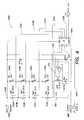
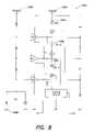
- FIG. 8illustrates a lighting apparatus according to another embodiment of the present invention employing operational amplifier power supplies to generate respective node voltages in a series-connected LED stack, and individual current sources for each LED.
- FIG. 9illustrates a lighting apparatus according to another embodiment of the present invention having different groupings of controllable channels associated with corresponding current sources.
- FIG. 10illustrates a lighting apparatus according to another embodiment of the present invention that is particularly configured to simulate a resistive load.
- FIGS. 11 and 12illustrate a “rail splitting” architecture to provide power to multiple lighting units from an operating voltage, according to one embodiment of the present invention.
- FIG. 1illustrates one example of a lighting unit 100 according to one embodiment of the present disclosure.
- Some general examples of LED-based lighting units similar to those that are described below in connection with FIG. 1may be found, for example, in U.S. Pat. No. 6,016,038, issued Jan. 18, 2000 to Mueller et al., entitled “Multicolored LED Lighting Method and Apparatus,” and U.S. Pat. No. 6,211,626, issued Apr. 3, 2001 to Lys et al, entitled “Illumination Components,” which patents are both hereby incorporated herein by reference.
- the lighting unit 100 shown in FIG. 1may be used alone or together with other similar lighting units in a system of lighting units (e.g., as discussed further below in connection with FIG. 2 ). Used alone or in combination with other lighting units, the lighting unit 100 may be employed in a variety of applications including, but not limited to, direct-view or indirect-view interior or exterior space (e.g., architectural) lighting and illumination in general, direct or indirect illumination of objects or spaces, theatrical or other entertainment-based/special effects lighting, decorative lighting, safety-oriented lighting, vehicular lighting, lighting associated with, or illumination of, displays and/or merchandise (e.g. for advertising and/or in retail/consumer environments), combined lighting or illumination and communication systems, etc., as well as for various indication, display and informational purposes.
- direct-view or indirect-view interior or exterior spacee.g., architectural
- lighting and illuminationin general
- direct or indirect illumination of objects or spacese.g., theatrical or other entertainment-based/special effects lighting
- decorative lighting, safety-oriented lightinge.g.
- one or more lighting units similar to that described in connection with FIG. 1may be implemented in a variety of products including, but not limited to, various forms of light modules or bulbs having various shapes and electrical/mechanical coupling arrangements (including replacement or “retrofit” modules or bulbs adapted for use in conventional sockets or fixtures), as well as a variety of consumer and/or household products (e.g., night lights, toys, games or game components, entertainment components or systems, utensils, appliances, kitchen aids, cleaning products, etc.) and architectural components (e.g., lighted panels for walls, floors, ceilings, lighted trim and ornamentation components, etc.).
- various forms of light modules or bulbs having various shapes and electrical/mechanical coupling arrangementsincluding replacement or “retrofit” modules or bulbs adapted for use in conventional sockets or fixtures
- consumer and/or household productse.g., night lights, toys, games or game components, entertainment components or systems, utensils, appliances, kitchen aids, cleaning products, etc.
- architectural componentse.g., lighted panels for
- the lighting unit 100 shown in FIG. 1includes one or more light sources 104 A, 104 B, 104 C, and 104 D (shown collectively as 104 ), wherein one or more of the light sources may be an LED-based light source that includes one or more light emitting diodes (LEDs).
- LEDslight emitting diodes
- any two or more of the light sourcesmay be adapted to generate radiation of different colors (e.g. red, green, blue); in this respect, as discussed above, each of the different color light sources generates a different source spectrum that constitutes a different “channel” of a “multi-channel” lighting unit.
- the lighting unitis not limited in this respect, as different numbers and various types of light sources (all LED-based light sources, LED-based and non-LED-based light sources in combination, etc.) adapted to generate radiation of a variety of different colors, including essentially white light, may be employed in the lighting unit 100 , as discussed further below.
- the lighting unit 100also may include a controller 105 that is configured to output one or more control signals to drive the light sources so as to generate various intensities of light from the light sources.
- the controller 105may be configured to output at least one control signal for each light source so as to independently control the intensity of light (e.g., radiant power in lumens) generated by each light source; alternatively, the controller 105 may be configured to output one or more control signals to collectively control a group of two or more light sources identically.
- control signalsthat may be generated by the controller to control the light sources include, but are not limited to, pulse modulated signals, pulse width modulated signals (PWM), pulse amplitude modulated signals (PAM), pulse code modulated signals (PCM) analog control signals (e.g., current control signals, voltage control signals), combinations and/or modulations of the foregoing signals, or other control signals.
- PWMpulse width modulated signals
- PAMpulse amplitude modulated signals
- PCMpulse code modulated signals
- one or more modulation techniquesprovide for variable control using a fixed current level applied to one or more LEDs, so as to mitigate potential undesirable or unpredictable variations in LED output that may arise if a variable LED drive current were employed.
- the controller 105may control other dedicated circuitry (not shown in FIG. 1 ) which in turn controls the light sources so as to vary their respective intensities.
- the intensity (radiant output power) of radiation generated by the one or more light sourcesis proportional to the average power delivered to the light source(s) over a given time period.
- one technique for varying the intensity of radiation generated by the one or more light sourcesinvolves modulating the power delivered to (i.e., the operating power of) the light source(s). For some types of light sources, including LED-based sources, this may be accomplished effectively using a pulse width modulation (PWM) technique.
- PWMpulse width modulation
- a fixed predetermined voltage V sourceis applied periodically across a given light source constituting the channel.
- the application of the voltage V sourcemay be accomplished via one or more switches, not shown in FIG. 1 , controlled by the controller 105 .
- a predetermined fixed current I sourcee.g., determined by a current regulator, also not shown in FIG. 1
- an LED-based light sourcemay include one or more LEDs, such that the voltage V source may be applied to a group of LEDs constituting the source, and the current I source may be drawn by the group of LEDs.
- the fixed voltage V source across the light source when energized, and the regulated current I source drawn by the light source when energized, determines the amount of instantaneous operating power P source of the light source (P sourceV source ⁇ I source ).
- P sourceV source ⁇ I source
- using a regulated currentmitigates potential undesirable or unpredictable variations in LED output that may arise if a variable LED drive current were employed.
- the PWM techniqueby periodically applying the voltage V source to the light source and varying the time the voltage is applied during a given on-off cycle, the average power delivered to the light source over time (the average operating power) may be modulated.
- the controller 105may be configured to apply the voltage V source to a given light source in a pulsed fashion (e.g., by outputting a control signal that operates one or more switches to apply the voltage to the light source), preferably at a frequency that is greater than that capable of being detected by the human eye (e.g., greater than approximately 100 Hz).
- a control signalthat operates one or more switches to apply the voltage to the light source
- a frequencythat is greater than that capable of being detected by the human eye
- an observer of the light generated by the light sourcedoes not perceive the discrete on-off cycles (commonly referred to as a “flicker effect”), but instead the integrating function of the eye perceives essentially continuous light generation.
- the pulse widthi.e.
- the controllervaries the average amount of time the light source is energized in any given time period, and hence varies the average operating power of the light source. In this manner, the perceived brightness of the generated light from each channel in turn may be varied.
- the controller 105may be configured to control each different light source channel of a multi-channel lighting unit at a predetermined average operating power to provide a corresponding radiant output power for the light generated by each channel.
- the controller 105may receive instructions (e.g., “lighting commands”) from a variety of origins, such as a user interface 118 , a signal source 124 , or one or more communication ports 120 , that specify prescribed operating powers for one or more channels and, hence, corresponding radiant output powers for the light generated by the respective channels.
- instructionse.g., “lighting commands”
- the controller 105may receive instructions (e.g., “lighting commands”) from a variety of origins, such as a user interface 118 , a signal source 124 , or one or more communication ports 120 , that specify prescribed operating powers for one or more channels and, hence, corresponding radiant output powers for the light generated by the respective channels.
- the prescribed operating powers for one or more channelse.g., pursuant to different instructions or lighting commands
- one or more of the light sources 104 A, 104 B, 104 C, and 104 D shown in FIG. 1may include a group of multiple LEDs or other types of light sources (e.g., various parallel and/or serial connections of LEDs or other types of light sources) that are controlled together by the controller 105 .
- one or more of the light sourcesmay include one or more LEDs that are adapted to generate radiation having any of a variety of spectra (i.e., wavelengths or wavelength bands), including, but not limited to, various visible colors (including essentially white light), various color temperatures of white light, ultraviolet, or infrared. LEDs having a variety of spectral bandwidths (e.g., narrow band, broader band) may be employed in various implementations of the lighting unit 100 .
- the lighting unit 100may be constructed and arranged to produce a wide range of variable color radiation.
- the lighting unit 100may be particularly arranged such that controllable variable intensity (i.e., variable radiant power) light generated by two or more of the light sources combines to produce a mixed colored light (including essentially white light having a variety of color temperatures).
- controllable variable intensityi.e., variable radiant power
- the color (or color temperature) of the mixed colored lightmay be varied by varying one or more of the respective intensities (output radiant power) of the light sources (e.g., in response to one or more control signals output by the controller 105 ).
- the controller 105may be particularly configured to provide control signals to one or more of the light sources so as to generate a variety of static or time-varying (dynamic) multi-color (or multi-color temperature) lighting effects.
- the controllermay include a processor 102 (e.g., a microprocessor) programmed to provide such control signals to one or more of the light sources.
- the processor 102may be programmed to provide such control signals autonomously, in response to lighting commands, or in response to various user or signal inputs.
- the lighting unit 100may include a wide variety of colors of LEDs in various combinations, including two or more of red, green, and blue LEDs to produce a color mix, as well as one or more other LEDs to create varying colors and color temperatures of white light.
- red, green and bluecan be mixed with amber, white, UV, orange, IR or other colors of LEDs.
- multiple white LEDs having different color temperaturese.g., one or more first white LEDs that generate a first spectrum corresponding to a first color temperature, and one or more second white LEDs that generate a second spectrum corresponding to a second color temperature different than the first color temperature
- Such combinations of differently colored LEDs and/or different color temperature white LEDs in the lighting unit 100can facilitate accurate reproduction of a host of desirable spectrums of lighting conditions, examples of which include, but are not limited to, a variety of outside daylight equivalents at different times of the day, various interior lighting conditions, lighting conditions to simulate a complex multicolored background, and the like.
- Other desirable lighting conditionscan be created by removing particular pieces of spectrum that may be specifically absorbed, attenuated or reflected in certain environments. Water, for example tends to absorb and attenuate most non-blue and non-green colors of light, so underwater applications may benefit from lighting conditions that are tailored to emphasize or attenuate some spectral elements relative to others.
- the lighting unit 100also may include a memory 114 to store information.
- the memory 114may be employed to store one or more lighting commands or programs for execution by the processor 126 (e.g., to generate one or more control signals for the light sources), as well as various types of data useful for generating variable color radiation (e.g., calibration information, discussed further below).
- the memory 114also may store one or more particular identifiers (e.g., a serial number, an address, etc.) that may be used either locally or on a system level to identify the lighting unit 100 .
- such identifiersmay be pre-programmed by a manufacturer, for example, and may be either alterable or non-alterable thereafter (e.g., via some type of user interface located on the lighting unit, via one or more data or control signals received by the lighting unit, etc.). Alternatively, such identifiers may be determined at the time of initial use of the lighting unit in the field, and again may be alterable or non-alterable thereafter.
- the lighting unit 100optionally may include one or more user interfaces 118 that are provided to facilitate any of a number of user-selectable settings or functions (e.g., generally controlling the light output of the lighting unit 100 , changing and/or selecting various pre-programmed lighting effects to be generated by the lighting unit, changing and/or selecting various parameters of selected lighting effects, setting particular identifiers such as addresses or serial numbers for the lighting unit, etc.).
- the communication between the user interface 118 and the lighting unitmay be accomplished through wire or cable, or wireless transmission.
- the controller 105 of the lighting unitmonitors the user interface 118 and controls one or more of the light sources 104 A, 104 B, 104 C and 104 D based at least in part on a user's operation of the interface.
- the controller 105may be configured to respond to operation of the user interface by originating one or more control signals for controlling one or more of the light sources.
- the processor 126may be configured to respond by selecting one or more pre-programmed control signals stored in memory, modifying control signals generated by executing a lighting program, selecting and executing a new lighting program from memory, or otherwise affecting the radiation generated by one or more of the light sources.
- the user interface 118may constitute one or more switches (e.g., a standard wall switch) that interrupt power to the controller 105 .
- the controller 105is configured to monitor the power as controlled by the user interface, and in turn control one or more of the light sources based at least in part on a duration of a power interruption caused by operation of the user interface.
- the controllermay be particularly configured to respond to a predetermined duration of a power interruption by, for example, selecting one or more pre-programmed control signals stored in memory, modifying control signals generated by executing a lighting program, selecting and executing a new lighting program from memory, or otherwise affecting the radiation generated by one or more of the light sources.
- FIG. 1also illustrates that the lighting unit 100 may be configured to receive one or more signals 122 from one or more other signal sources 124 .
- the controller 105 of the lighting unitmay use the signal(s) 122 , either alone or in combination with other control signals (e.g., signals generated by executing a lighting program, one or more outputs from a user interface, etc.), so as to control one or more of the light sources 104 A, 104 B, 104 C and 104 D in a manner similar to that discussed above in connection with the user interface.
- control signalse.g., signals generated by executing a lighting program, one or more outputs from a user interface, etc.
- Examples of the signal(s) 122 that may be received and processed by the controller 105include, but are not limited to, one or more audio signals, video signals, power signals, various types of data signals, signals representing information obtained from a network (e.g., the Internet), signals representing one or more detectable/sensed conditions, signals from lighting units, signals consisting of modulated light, etc.
- the signal source(s) 124may be located remotely from the lighting unit 100 , or included as a component of the lighting unit. In one embodiment, a signal from one lighting unit 100 could be sent over a network to another lighting unit 100 .
- a signal source 124that may be employed in, or used in connection with, the lighting unit 100 of FIG. 1 include any of a variety of sensors or transducers that generate one or more signals 122 in response to some stimulus.
- sensorsinclude, but are not limited to, various types of environmental condition sensors, such as thermally sensitive (e.g., temperature, infrared) sensors, humidity sensors, motion sensors, photosensors/light sensors (e.g., photodiodes, sensors that are sensitive to one or more particular spectra of electromagnetic radiation such as spectroradiometers or spectrophotometers, etc.), various types of cameras, sound or vibration sensors or other pressure/force transducers (e.g., microphones, piezoelectric devices), and the like.
- thermally sensitivee.g., temperature, infrared
- humidity sensorse.g., humidity sensors, motion sensors, photosensors/light sensors (e.g., photodiodes, sensors that are sensitive to one or more particular spectra of electromagnetic radiation such as
- a signal source 124includes various metering/detection devices that monitor electrical signals or characteristics (e.g., voltage, current, power, resistance, capacitance, inductance, etc.) or chemical/biological characteristics (e.g., acidity, a presence of one or more particular chemical or biological agents, bacteria, etc.) and provide one or more signals 122 based on measured values of the signals or characteristics.
- electrical signals or characteristicse.g., voltage, current, power, resistance, capacitance, inductance, etc.
- chemical/biological characteristicse.g., acidity, a presence of one or more particular chemical or biological agents, bacteria, etc.
- a signal source 124include various types of scanners, image recognition systems, voice or other sound recognition systems, artificial intelligence and robotics systems, and the like.
- a signal source 124could also be a lighting unit 100 , another controller or processor, or any one of many available signal generating devices, such as media players, MP3 players, computers, DVD players, CD players, television signal sources, camera signal sources, microphones, speakers, telephones, cellular phones, instant messenger devices, SMS devices, wireless devices, personal organizer devices, and many others.
- signal generating devicessuch as media players, MP3 players, computers, DVD players, CD players, television signal sources, camera signal sources, microphones, speakers, telephones, cellular phones, instant messenger devices, SMS devices, wireless devices, personal organizer devices, and many others.
- the lighting unit 100 shown in FIG. 1also may include one or more optical elements 130 to optically process the radiation generated by the light sources 104 A, 104 B, 104 C, and 104 D.
- one or more optical elementsmay be configured so as to change one or both of a spatial distribution and a propagation direction of the generated radiation.
- one or more optical elementsmay be configured to change a diffusion angle of the generated radiation.
- one or more optical elements 130may be particularly configured to variably change one or both of a spatial distribution and a propagation direction of the generated radiation (e.g., in response to some electrical and/or mechanical stimulus).
- optical elementsexamples include, but are not limited to, reflective materials, refractive materials, translucent materials, filters, lenses, mirrors, and fiber optics.
- the optical element 130also may include a phosphorescent material, luminescent material, or other material capable of responding to or interacting with the generated radiation.
- the lighting unit 100may include one or more communication ports 125 to facilitate coupling of the lighting unit 100 to any of a variety of other devices.
- one or more communication ports 125may facilitate coupling multiple lighting units together as a networked lighting system, in which at least some of the lighting units are addressable (e.g., have particular identifiers or addresses) and are responsive to particular data transported across the network.
- the controller 105 of each lighting unit coupled to the networkmay be configured to be responsive to particular data (e.g., lighting control commands) that pertain to it (e.g., in some cases, as dictated by the respective identifiers of the networked lighting units).
- particular datae.g., lighting control commands
- a given controllermay read the data and, for example, change the lighting conditions produced by its light sources according to the received data (e.g., by generating appropriate control signals to the light sources).
- each lighting unit coupled to the networkmay be loaded, for example, with a table of lighting control signals that correspond with data the processor 126 of the controller receives. Once the processor 126 receives data from the network, the processor may consult the table to select the control signals that correspond to the received data, and control the light sources of the lighting unit accordingly.
- the processor 102 of a given lighting unitmay be configured to interpret lighting instructions/data that are received in a DMX protocol (as discussed, for example, in U.S. Pat. Nos. 6,016,038 and 6,211,626), which is a lighting command protocol conventionally employed in the lighting industry for some programmable lighting applications.
- DMX protocollighting instructions are transmitted to a lighting unit as control data that is formatted into packets including 512 bytes of data, in which each data byte is constituted by 8-bits representing a digital value of between zero and 255. These 512 data bytes are preceded by a “start code” byte.
- An entire “packet” including 513 bytes (start code plus data)is transmitted serially at 250 kbit/s pursuant to RS-485 voltage levels and cabling practices, wherein the start of a packet is signified by a break of at least 88 microseconds.
- each data byte of the 512 bytes in a given packetis intended as a lighting command for a particular “channel” of a multi-channel lighting unit, wherein a digital value of zero indicates no radiant output power for a given channel of the lighting unit (i.e., channel off), and a digital value of 255 indicates full radiant output power (100% available power) for the given channel of the lighting unit (i.e., channel full on).
- a lighting command in DMX protocolmay specify each of a red channel command, a green channel command, and a blue channel command as eight-bit data (i.e., a data byte) representing a value from 0 to 255.
- the maximum value of 255 for any one of the color channelsinstructs the processor 102 to control the corresponding light source(s) to operate at maximum available power (i.e., 100%) for the channel, thereby generating the maximum available radiant power for that color (such a command structure for an R-G-B lighting unit commonly is referred to as 24-bit color control).
- a given communication link employing the DMX protocolconventionally can support up to 512 different lighting unit channels.
- a given lighting unit designed to receive communications formatted in the DMX protocolgenerally is configured to respond to only one or more particular data bytes of the 512 bytes in the packet corresponding to the number of channels of the lighting unit (e.g., in the example of a three-channel lighting unit, three bytes are used by the lighting unit), and ignore the other bytes, based on a particular position of the desired data byte(s) in the overall sequence of the 512 data bytes in the packet.
- DMX-based lighting unitsmay be equipped with an address selection mechanism that may be manually set by a user/installer to determine the particular position of the data byte(s) that the lighting unit responds to in a given DMX packet.
- lighting units suitable for purposes of the present disclosureare not limited to a DMX command format, as lighting units according to various embodiments may be configured to be responsive to other types of communication protocols/lighting command formats so as to control their respective light sources.
- the processor 102may be configured to respond to lighting commands in a variety of formats that express prescribed operating powers for each different channel of a multi-channel lighting unit according to some scale representing zero to maximum available operating power for each channel.
- the processor 102 of a given lighting unitmay be configured to interpret lighting instructions/data that are received in a conventional Ethernet protocol (or similar protocol based on Ethernet concepts).
- Ethernetis a well-known computer networking technology often employed for local area networks (LANs) that defines wiring and signaling requirements for interconnected devices forming the network, as well as frame formats and protocols for data transmitted over the network.
- LANslocal area networks
- Devices coupled to the networkhave respective unique addresses, and data for one or more addressable devices on the network is organized as packets.
- Each Ethernet packetincludes a “header” that specifies a destination address (to where the packet is going) and a source address (from where the packet came), followed by a “payload” including several bytes of data (e.g., in Type II Ethernet frame protocol, the payload may be from 46 data bytes to 1500 data bytes).
- a packetconcludes with an error correction code or “checksum.”
- the payload of successive Ethernet packets destined for a given lighting unit configured to receive communications in an Ethernet protocolmay include information that represents respective prescribed radiant powers for different available spectra of light (e.g., different color channels) capable of being generated by the lighting unit.
- the processor 102 of a given lighting unitmay be configured to interpret lighting instructions/data that are received in a serial-based communication protocol as described, for example, in U.S. Pat. No. 6,777,891.
- a serial-based communication protocolmultiple lighting units 100 are coupled together via their communication ports 120 to form a series connection of lighting units (e.g., a daisy-chain or ring topology), wherein each lighting unit has an input communication port and an output communication port. Lighting instructions/data transmitted to the lighting units are arranged sequentially based on a relative position in the series connection of each lighting unit.
- each lighting unit in the series connectionreceives data, it “strips off” or extracts one or more initial portions of the data sequence intended for it and transmits the remainder of the data sequence to the next lighting unit in the series connection.
- the processor 102 of each lighting unit in the series connectionreceives data, it “strips off” or extracts one or more initial portions of the data sequence intended for it and transmits the remainder of the data sequence to the next lighting unit in the series connection.
- three multi-bit valuesone multi-bit value per channel
- each lighting unitmay include respective prescribed radiant powers for different available spectra of light (e.g., different color channels) capable of being generated by the lighting unit.
- each multi-bit value per channelmay be an 8-bit value, or other number of bits (e.g., 12, 16, 24, etc.) per channel, depending in part on a desired control resolution for each channel.
- a flagis associated with each portion of a data sequence representing data for multiple channels of a given lighting unit, and an entire data sequence for multiple lighting units is transmitted completely from lighting unit to lighting unit in the serial connection.
- a lighting unit in the serial connectionreceives the data sequence, it looks for the first portion of the data sequence in which the flag indicates that a given portion (representing one or more channels) has not yet been read by any lighting unit. Upon finding such a portion, the lighting unit reads and processes the portion to provide a corresponding light output, and sets the corresponding flag to indicate that the portion has been read. Again, the entire data sequence is transmitted completely from lighting unit to lighting unit, wherein the state of the flags indicate the next portion of the data sequence available for reading and processing.
- the controller 105 a given lighting unit configured for a serial-based communication protocolmay be implemented as an application-specific integrated circuit (ASIC) designed to specifically process a received stream of lighting instructions/data according to the “data stripping/extraction” process or “flag modification” process discussed above. More specifically, in one exemplary embodiment of multiple lighting units coupled together in a series interconnection to form a network, each lighting unit includes an ASIC-implemented controller 105 having the functionality of the processor 102 , the memory 114 and communication port(s) 120 shown in FIG. 1 (optional user interface 118 and signal source 124 of course need not be included in some implementations). Such an implementation is discussed in detail in U.S. Pat. No. 6,777,891.
- ASICapplication-specific integrated circuit
- the light source 104may include and/or be coupled to one or more power sources 108 .
- examples of power source(s) 108include, but are not limited to, AC power sources, DC power sources, batteries, solar-based power sources, thermoelectric or mechanical-based power sources and the like.
- the power source(s) 108may include or be associated with one or more power conversion devices or power conversion circuitry (e.g., in some cases internal to the light source 104 ) that convert power received by an external power source to a form suitable for operation of the various internal circuit components and light sources of the light source 104 .
- power conversion devices or power conversion circuitrye.g., in some cases internal to the light source 104
- the controller 105 of the light source 104may be configured to accept a standard A.C. line voltage from the power source 108 and provide appropriate D.C. operating power for the light sources and other circuitry of the lighting unit based on concepts related to DC-DC conversion, or “switching” power supply concepts.
- the controller 105may include circuitry to not only accept a standard A.C. line voltage but to ensure that power is drawn from the line voltage with a significantly high power factor.
- FIG. 2illustrates an example of a networked lighting system 200 according to one embodiment of the present disclosure.
- a number of lighting units 100similar to those discussed above in connection with FIG. 1 , are coupled together to form the networked lighting system. It should be appreciated, however, that the particular configuration and arrangement of lighting units shown in FIG. 2 is for purposes of illustration only, and that the disclosure is not limited to the particular system topology shown in FIG. 2 .
- the networked lighting system 200may be configured flexibly to include one or more user interfaces, as well as one or more signal sources such as sensors/transducers.
- one or more user interfaces and/or one or more signal sourcessuch as sensors/transducers (as discussed above in connection with FIG. 1 ) may be associated with any one or more of the lighting units of the networked lighting system 200 .
- one or more user interfaces and/or one or more signal sourcesmay be implemented as “stand alone” components in the networked lighting system 200 .
- these devicesmay be “shared” by the lighting units of the networked lighting system.
- one or more user interfaces and/or one or more signal sourcessuch as sensors/transducers may constitute “shared resources” in the networked lighting system that may be used in connection with controlling any one or more of the lighting units of the system.
- the lighting system 200may include one or more lighting unit controllers (hereinafter “LUCs”) 208 A, 208 B, 208 C, and 208 D, wherein each LUC is responsible for communicating with and generally controlling one or more lighting units 100 coupled to it.
- LUCslighting unit controllers
- FIG. 2illustrates one lighting unit 100 coupled to each LUC, it should be appreciated that the disclosure is not limited in this respect, as different numbers of lighting units 100 may be coupled to a given LUC in a variety of different configurations (serially connections, parallel connections, combinations of serial and parallel connections, etc.) using a variety of different communication media and protocols.
- each LUCin turn may be coupled to a central controller 202 that is configured to communicate with one or more LUCs.
- FIG. 2shows four LUCs coupled to the central controller 202 via a generic connection 212 (which may include any number of a variety of conventional coupling, switching and/or networking devices), it should be appreciated that according to various embodiments, different numbers of LUCs may be coupled to the central controller 202 .
- the LUCs and the central controllermay be coupled together in a variety of configurations using a variety of different communication media and protocols to form the networked lighting system 200 .
- the interconnection of LUCs and the central controller, and the interconnection of lighting units to respective LUCsmay be accomplished in different manners (e.g., using different configurations, communication media, and protocols).
- the central controller 202 shown in FIG. 2may by configured to implement Ethernet-based communications with the LUCs, and in turn the LUCs may be configured to implement one of Ethernet-based, DMX-based, or serial-based protocol communications with the lighting units 100 (as discussed above, exemplary serial-based protocols suitable for various network implementation are discussed in detail in U.S. Pat. No. 6,777,891.
- each LUCmay be configured as an addressable Ethernet-based controller and accordingly may be identifiable to the central controller 202 via a particular unique address (or a unique group of addresses and/or other identifiers) using an Ethernet-based protocol.
- the central controller 202may be configured to support Ethernet communications throughout the network of coupled LUCs, and each LUC may respond to those communications intended for it.
- each LUCmay communicate lighting control information to one or more lighting units coupled to it, for example, via an Ethernet, DMX, or serial-based protocol, in response to the Ethernet communications with the central controller 202 (wherein the lighting units are appropriately configured to interpret information received from the LUC in the Ethernet, DMX, or serial-based protocols).
- the LUCs 208 A, 208 B, and 208 C shown in FIG. 2may be configured to be “intelligent” in that the central controller 202 may be configured to communicate higher level commands to the LUCs that need to be interpreted by the LUCs before lighting control information can be forwarded to the lighting units 100 .
- a lighting system operatormay want to generate a color changing effect that varies colors from lighting unit to lighting unit in such a way as to generate the appearance of a propagating rainbow of colors (“rainbow chase”), given a particular placement of lighting units with respect to one another.
- the operatormay provide a simple instruction to the central controller 202 to accomplish this, and in turn the central controller may communicate to one or more LUCs using an Ethernet-based protocol high level command to generate a “rainbow chase.”
- the commandmay contain timing, intensity, hue, saturation or other relevant information, for example.
- a given LUCmay then interpret the command and communicate further commands to one or more lighting units using any one of a variety of protocols (e.g., Ethernet, DMX, serial-based), in response to which the respective sources of the lighting units are controlled via any of a variety of signaling techniques (e.g., PWM).
- one or more LUCs of a lighting networkmay be coupled to a series connection of multiple lighting units 100 (e.g., see LUC 208 A of FIG. 2 , which is coupled to two series-connected lighting units 100 ).
- each LUC coupled in this manneris configured to communicate with the multiple lighting units using a serial-based communication protocol, examples of which were discussed above.
- a given LUCmay be configured to communicate with a central controller 202 , and/or one or more other LUCs, using an Ethernet-based protocol, and in turn communicate with the multiple lighting units using a serial-based communication protocol.
- a LUCmay be viewed in one sense as a protocol converter that receives lighting instructions or data in the Ethernet-based protocol, and passes on the instructions to multiple serially-connected lighting units using the serial-based protocol.
- a given LUCsimilarly may be viewed as a protocol converter that receives lighting instructions or data in the Ethernet protocol, and passes on instructions formatted in a DMX protocol.
- one or more lighting units as discussed aboveare capable of generating highly controllable variable color light over a wide range of colors, as well as variable color temperature white light over a wide range of color temperatures.
- a series interconnection of multiple LEDsmay permit the use of operating voltages that are significantly higher than typical LED forward voltages, and may also allow operation of multiple LEDs or LED-based lighting units without requiring a transformer between a source of power (e.g., wall power or line voltage such as 120 VAC or 240 VAC) and the loads (i.e., multiple series-connected loads may be operated “directly” from a line voltage).
- a source of powere.g., wall power or line voltage such as 120 VAC or 240 VAC
- loadsi.e., multiple series-connected loads may be operated “directly” from a line voltage
- embodiments of the present inventiongenerally relate to methods and apparatus for controlling LED-based light sources, in which respective elements of a multi-element light source, and/or multiple light sources themselves, are coupled in series to receive operating power.
- respective elements of a multi-element light source, and/or multiple light sources themselvesare coupled in series to receive operating power.
- LEDs or LED-based lighting unitsmay be coupled in series depending at least in part on the nominal operating voltage of each LED or lighting unit, and the expected nominal supply voltage provided by an available source of power.
- FIG. 3is a block diagram of an LED-based lighting apparatus 100 A including multiple series-connected LEDs, according to one embodiment of the present invention.
- multiple LEDsare connected nominally in series between a first node 108 A and a second node 108 B to which an operating voltage is applied (a power source 108 was generally discussed above in connection with FIG. 1 ) to form a series-connected “stack” of devices.
- a power source 108was generally discussed above in connection with FIG. 1
- the position of one or more LEDs in the “stack” of series-connected devices, relative to one of the two voltage potentials respectively applied to the first and second nodesis referred to as the “height” in the “stack.”
- FIG. 3a first light source 104 B (represented by a single LED for purposes of illustration) is shown at a first height in the stack, and a second light source 104 A (again represented by a single LED for purposes of illustration) is shown at a second height in the stack.
- FIG. 3illustrates an exemplary apparatus with two light sources, as noted above it should be appreciated that the present invention is not limited in this respect, as virtually any number of light sources may connected in series in a given apparatus.
- FIG. 3illustrates an exemplary apparatus with two light sources, as noted above it should be appreciated that the present invention is not limited in this respect, as virtually any number of light sources may connected in series in a given apparatus.
- the current source 310also shows a current source 310 connected in series with the LEDs between the first and second nodes; in one aspect, the current source 310 sets a series current (I series ) flowing between the first and second nodes, through one or more of the series-connected LEDs, when the operating voltage is applied across the first and second nodes.
- I seriesseries current
- the light sources 104 A and 104 B of the apparatus 100 A shown in FIG. 3each may include a single LED or multiple LEDs (e.g., interconnected in a parallel arrangement). Additionally, the light sources 104 A and 104 B may generate radiation having similar or virtually identical spectrums (e.g., constituting colored or essentially white light), or the light sources 104 A and 104 B may generate respectively different spectrums. Accordingly, at each different height in the stack of series-connected devices, in different implementations one or more LEDs may be employed; furthermore, different spectrums of colored light (or different color temperatures of white light) may be generated at different heights in the stack, or essentially a same spectrum of light may be generated at each height in the stack.
- each of the light sources 104 A and 104 B in FIG. 3is referred to simply as an LED, although it should be appreciated that various implementations of the present invention are not limited to having a single LED at each height in the stack of series-connected devices.
- the apparatus 100 Aincludes one or more controllable current paths 312 A and 312 B (abbreviated as “CCP”) connected in parallel with one or more of the series-connected LEDs.
- the controllable current pathsmay be implemented as controllable switches to completely divert the series current I series around a given LED, or as controllable variable or fixed current sources configured to divert all or only a portion of the series current around the given LED. In this manner, the brightness of a given LED may be controlled and, in the extreme, the LED may be completely turned off by diverting current completely around it. While FIG.
- the apparatus 100 Aincludes a controller 105 A configured to control one or more controllable current paths 312 A and 312 B via the respective control signals 314 A and 314 B.
- the controlleris shown coupled to the operating voltage applied across the first and second nodes so as to obtain operating power.
- the controller 105 Amay be coupled in series with the current source 310 and the series-connected LEDs so as to obtain operating power.
- the controller 105 Amay operate one or more controllable current paths 312 A and 312 B based on data received as lighting instructions via one or more communication ports 120 A (as discussed above in connection with FIGS. 1 and 2 ).
- the controllermay be configured to be responsive to a serial data protocol, and include at least two communication ports (e.g., an data input port and a data output port) to facilitate serial data communication amongst respective controllers of multiple lighting apparatus similar to the apparatus 100 A.
- the controller 105 Amay be configured to operate one or more controllable current paths based on one or more measured parameters related to the available operating voltage applied across the first and second nodes 108 A and 108 B. More specifically, in one embodiment, the ability to divert current partially or fully around one or more series-connected LEDs is employed in circumstances in which a nominal expected operating voltage applied across the first and second nodes falls below a minimum operating voltage necessary to energize all of the series-connected devices. In various implementations, this minimum operating voltage may depend at least in part on the number and type of LEDs employed in the series-connected stack of devices and, more specifically, the respective forward operating voltages of the individual LEDs employed in the stack.
- controllable current pathsmay be switches that completely divert current around a corresponding LED so as to essentially short out the LED and remove it from the series connection of devices. In this manner, the operating voltage necessary to operate the remaining series-connected LEDs is lowered by the individual operating (forward) voltage of each LED that is shorted out due to current diversion.
- the controllermay be configured to control one or more of the controllable current paths so as to increase an amount of current that is diverted around a corresponding LED (e.g., short out the corresponding LED) when the monitored parameter(s) indicate that the operating voltage is less than a predetermined threshold value.
- the predetermined threshold valuemay represent a minimum operating voltage necessary to energize all of the series-connected LEDs in a given apparatus and, in this manner, may depend at least in part on the number of LEDs in a given apparatus and the respective forward voltages of the LEDs.
- the controllermay appropriately control one or more of the controllable current paths to add one or more “shorted” LEDs back into the series-connected stack so that they are energized by the series current. More generally, via the monitored parameter(s) representative of the operating voltage, the controller may make a determination (and may do so virtually continuously or periodically) as to the number of LEDs that may be effectively energized based on the available operating voltage at any given time, and control one or more controllable current paths accordingly to energize all or less than all of the series-connected LEDs of the apparatus. As discussed further below, the controller 105 A may implement a variety of control strategies for statically or dynamically controlling one or more of the controllable current paths over a given time period and/or range of operating voltage conditions.
- the current source 310may be a fixed current source (i.e., the value of the series current I series may be fixed), or the current source may be a controllable current source such that the series current I series is variable.
- the controller 105 Amay additionally control the current source 310 , as indicated by the dashed control connection 315 shown in FIG. 3 .
- the controllermay control the current source to set the series current based at least in part on the monitored parameter(s) representing the operating voltage, and to increase or decrease the series current based on changes in the available operating voltage according to any of a variety of relationships (e.g., proportional, inversely proportional, etc.).
- the controllermay be configured to control the current source so as to increase the series current as the operating voltage decreases so as to maintain an essentially constant brightness of light generated by energized LEDs of the apparatus.
- the controller 105 Amay also change the value of series current to reduce brightness, or otherwise change the series current based on a change in the operating voltage.
- Various dynamic relationships between the series current and the operating voltagemay be effected by the controller 105 A; for example, in one implementation, the series current may be slowly reduced as the operating voltage decreases, but then increased by some amount (e.g., 25%) when the LED shorting process begins. In this manner, there would be no sudden decrease in overall brightness as the operating voltage decreases.
- the controller 105 Amay control the current source 310 so as to duty cycle modulate the series current, to provide either a fixed or variable average series current.
- FIG. 4is a diagram illustrating an exemplary circuit implementation of the apparatus 100 A shown in FIG. 3 , according to one embodiment of the present invention.
- the apparatus of FIG. 4is particularly well-suited for automotive lighting applications in which nominal expected operating voltages are in the range of approximately 12 to 14.5 Volts.
- nominal expected operating voltagesare in the range of approximately 12 to 14.5 Volts.
- the available operating voltage for automobile accessories when an engine is running and the electrical system is chargingtypically is between 13.8 to 14.5 Volts; however, when the engine is not running, the available operating voltage can drop quickly to 12 to 12.8 Volts, or even lower (e.g., when high loads are present, and/or as the automobile battery discharges further).
- an apparatus thusly configuredis based on a principle of “constant area cost;” namely, an LED semiconductor structure of a fixed size costs a fairly fixed amount to implement, independent of how many sections into which it may be divided. Thus, if an LED semiconductor structure is divided into four sections which are then connected in series, a device results that has essentially the same cost as one LED, operates at a quarter of the current, and has an operating voltage four time that of the forward voltage of a single LED.
- a lighting apparatus based on series-connected LEDsneeds to take into consideration the complete range of possible available operating voltages; i.e., if the available operating voltage from the automobile electrical system falls below approximately 13.0 to 13.5 Volts, there may not be sufficient voltage to energize all of the four series-connected LEDs.
- four series-connected LEDs 104 A- 104 Dare employed together with four controllable current paths 312 A- 312 D, in parallel with the LEDs in a one-to-one correspondence, and responsive to corresponding control signals 314 A- 314 D provided by the controller 105 A.
- the controllable current pathsare implemented as single-pole single-throw (SPST) switches SW 1 -SW 4 so as to divert the series current I series around corresponding LEDs.
- the current source 310is implemented by operational amplifier U 7 A, N-type field effect transistor Q 35 and resistor R 41 . In the circuit of FIG. 4 , the current source 310 is not under the control of the controller 105 A, but rather the series current I series provided by the current source 310 tracks the operating voltage via the voltage divider formed by resistors R 43 and R 42 .
- the controller 105 A in the circuit of FIG. 4may be coupled between the first and second nodes 108 A and 108 B to obtain operating power directly from the operating voltage applied to these nodes. Additionally, the controller may optionally include a first communication port 120 A and a second communication port 120 B to transmit and receive data representing various information, as discussed further below. As also discussed above in connection with FIG. 3 , the controller 105 in the circuit of FIG. 4 may implement a variety of control techniques to operate the controllable current paths formed by the switches SW 1 -SW 4 .
- the controller 105 Amay begin controlling the switches SW 1 -SW 4 so as to short out one LED at a time (e.g., in a timed sequence) so that all LEDs appear to remain lit to an observer; stated differently, as the operating voltage decreases to a level that is insufficient to appropriately provide power to four series-connected LEDs, only three or fewer of the LEDs are simultaneously energized at any given time. In this manner, the controller intermittently diverts the series current around respective LEDs.
- different groupings of less than four LEDsare successively energized in a manner that is generally imperceptible to an observer.
- more than one LEDmay be shorted at the same time to allow further reductions in operating voltage while still generating light from the apparatus (e.g., only two LEDs may be energized at any given time, with different groups of two LEDs successively energized at an appropriate rate so as to be generally imperceptible to an observer).
- the controller 105 Amay employ any one or more of a number of techniques for monitoring one or more parameters representative of the operating voltage applied between the nodes 108 A and 108 B, and determining an appropriate number of LEDs that may be energized so as to effectively control the controllable current paths implemented by the switches SW 1 -SW 4 .
- the controller 105 Amay include one or more inputs to receive signals to monitor one or more of the operating voltage itself (via the line 324 ), a drain voltage of the FET Q 35 (via the line 320 ), and a gate voltage of the FET Q 35 (via the line 322 ).
- a gate voltage of approximately 4 Voltsindicates that the operating voltage has fallen to a value at which it is necessary to short out at least one LED
- a drain voltage of approximately 5 Voltsindicates a sufficient operating voltage to include all four LEDs in the series-connected stack.
- the controller 105 Amonitors only one of the drain and gate voltage of the FET Q 35 , and relies on accurate sensing of high and low drain voltages to achieve the decision, or speculative operation of the switches to determine the correct number of LEDs to short.
- the controller 105 Amay directly monitor the operating voltage, and employ a predictive strategy in which the monitored operating voltage maps directly to some number of shorted LEDs.
- the controllermay employ one or more predetermined threshold values, and as the operating voltage falls below a given predetermined threshold value, one or more LEDs are required to be shorted out.
- Various other techniquesmay be used, including indirectly estimating the drain, source, and/or gate voltage of FET Q 35 , with the goal of determining the correct number of LEDs to short.
- controller 105 Adoes not control the current source 310 in the circuit of FIG. 4
- the controller 105 Amay also change the value of the series current flowing through the string of energized LEDs, and may duty cycle modulate the current source, to maintain overall generated light brightness, reduce brightness, or otherwise change some aspect of operation of the apparatus based on a change in the operating voltage.
- the apparatus 100 Abased generally on the circuit architecture shown in FIG.
- the current sourcemay be implemented in any one of numerous ways known to those of ordinary skill in the relevant arts, including circuits employing one or more operational amplifiers, and n-type or p-type transistors such as BJTs or FETs.
- the controllable current paths 312 A- 312 D implemented as the switches SW 1 -SW 4may be of various designs.
- FIGS. 5A through 5Dillustrate four non-limiting exemplary circuits, any one of which may for employed for implementing the switches SW 1 -SW 4 shown in FIG. 4 .
- the circuit diagrams in FIGS. 5A-5Drepresent four different possibilities for the switch SW 4 (controllable current path 312 A) shown in FIG. 4 , wherein the nodes 313 A and 313 B for connection across the LED 104 A are indicated in the figures.
- any one of the switch designs shown in FIGS. 5A-5Dmay be employed for any one or more of the switches SW 1 -SW 4 shown in FIG. 4 .
- the switchesmay include one or both of n-type or p-type devices.
- a capacitive charge pump or boost cap architecturemay be employed to increase the available switch gate voltages.
- controller 105 A of FIG. 4may successively control different ones, or multiple different ones, of the switches SW 1 -SW 4 in an intermittent manner, as discussed above it should be appreciated that a number of control techniques may be implemented by the controller 105 A according to various embodiments so as to control the controllable current paths.
- current pathsmay be controlled sequentially, according to some predetermined or random order and according to a variety of time scales.
- rate at which different current paths are controlledmay be selected to be sufficiently faster than the rate at which a typical observer is able to discern perceptible differences in light characteristics (e.g., greater than approximately 50-60 Hz). In other embodiments of lighting apparatus similar to those shown in FIGS.
- a lighting apparatusmay include one or more optical elements (e.g., as discussed above in connection with FIG. 1 ) to mix, diffuse, combine or otherwise optically process the light generated by respective LEDs, such that the resulting perceived light is relatively independent of which particular LEDs are energized at any given time.
- optical elementse.g., as discussed above in connection with FIG. 1
- periodic, sequential or intermittent operation of the controllable current paths to switch one or more LEDs in and out of the series-connected stack, or otherwise divert some portion of current around one or more LEDsmay not be necessary; for example, there may be some applications in which it is acceptable to simply choose a particular operating state (e.g., some number of LEDs energized) based on available operating voltage at a given instant, and maintain that state for some period of time or indefinitely.
- a particular operating statee.g., some number of LEDs energized
- available operating voltagemay be monitored/sampled at any of a variety of intervals, and various control techniques implemented based on the sampled operating voltage.
- the controller 105 Amay be configured to control the controllable current paths or switches SW 1 -SW 4 such that the overall appearance of the generated light perceivably changes to an observer when the operating voltage is insufficient to operate all LEDs in the series-connected stack; i.e., it may be useful and/or desirable to make an observer aware of the reduced operating voltage through a perceivable change in the quality (e.g., brightness) of generated light. If different color LEDs are employed, this type of indication can be quite visible (i.e., quality changes in the light due to changes in operating voltage may involve brightness and color).
- the LEDs of the apparatus 100 A shown in FIG. 4may be of the same color (or color temperature of white) or different colors (or different color temperatures of white).
- the physical arrangement of different color or color temperature LEDs in a given apparatus, and/or the control technique implemented by the controller 105 Amay exploit the use of different color or different color temperature LEDs to create various lighting effects.
- the plurality of series-connected LEDsmay include at least one first LED for generating first radiation having a first spectrum, and at least one second LED for generating second radiation having a second spectrum different than the first spectrum, and the controller may control the controllable current paths in a predetermined manner based at least in part on the different spectrums of the LEDs.
- the first LEDmay include a first white LED, such that the first spectrum corresponds to a first color temperature
- the second LEDmay include a second white LED, such that the second spectrum corresponds to a second color temperature different than the first color temperature.
- the controllermay control the controllable current paths such that an overall color temperature of the light generated by the apparatus, based on at least one of the first spectrum and the second spectrum, decreases as the operating voltage decreases. For example, if warm white LEDs are used in some positions and cool white LEDs are used in others, then the controller may be configured to preferentially maintain energized the warm LEDs as operating voltage is reduced to mimic the effect produced by an incandescent light bulb.
- the switching actioncan be quite coarse, and still create a desired quality of light output.
- the apparatusis not limited in this respect, as embodiments with fewer (as few as two) or more than four LEDs are contemplated according to the present disclosure, as discussed above in connection with FIG. 3 . More generally, it should be appreciated that while an example of an automotive application was provided above in connection with the apparatus shown in FIG. 4 , various implementations of the present invention are not necessarily limited to automotive applications nor the particular range of contemplated operating voltages for such applications. In one respect, the number of series-connected LEDs in an apparatus having similar construction and functionality to that shown in FIGS. 3 and 4 may be dictated in part by the nominal operating voltage and range of expected operating voltages in a given application.
- LEDs each having a forward voltage of approximately 3.0 to 3.3 Voltsmay be particularly well-suited for operating voltages of approximately 13.0 to 14.5 Volts (e.g., as found in automotive applications)
- an apparatus based on two LEDs each having a forward voltage of from 2.5 to 3 VDCmay be particularly well-suited for applications involving operating voltages of 6 to 9 VDC
- an apparatus having seven series-connected LEDsmay be particularly well-suited for applications involving operating voltages of approximately 24 Volts.
- apparatus according to the present invention including any number of LEDsmay be contemplated for virtually any range of expected operating voltage for a variety of applications.
- more than one LEDmay be controlled by a given controllable current path, including groups of parallel-connected LEDs at a given height in the series-connected stack, or having a single controllable current path controlling LEDs at two or more heights in the series-connected stack (wherein, at each height, there may be one or more LEDs).
- a given controllable current pathincluding groups of parallel-connected LEDs at a given height in the series-connected stack, or having a single controllable current path controlling LEDs at two or more heights in the series-connected stack (wherein, at each height, there may be one or more LEDs).
- not all LEDs employed in a series-connected stackneed to be controllable with respect to current diversion, as also discussed above in connection with FIG. 3 .
- the physical layout of the LEDs in a realized devicemay be tailored to optimize optical efficiency (e.g., uncontrolled LEDs may be centered within the optical system).
- a lighting apparatus similar to that shown in FIGS. 3 and 4based on multiple series-connected LEDs, one or more controllable current paths connected in parallel with one or more of the series-connected LEDs, and a controller to control one or more of the controllable current paths, may be implemented as one or more integrated circuits.
- integrated circuit implementationsmay be appropriately packaged for ease of installation, deployment, and/or use in any one of a number of applications, including those applications in which conventional operating voltages are readily available.
- the apparatusmay be implemented as one or more integrated circuits and included in a package that facilitates installation and use in an automotive environment.
- all of the components of the circuitry shown in FIG. 4may be implemented on a single integrated circuit chip, or the LEDs may be implemented on one chip and the associated control circuitry implemented on another chip and stacked with the LED chip.
- LEDsare first attached to a “submount” which is often a semiconductor device, usually with reverse bias protection diodes, or zener diodes to prevent device failure due to high transient currents or voltages.
- the circuitry shown in FIG. 4can be fully integrated, and requires very little capacitance for operation; thus, the LEDs and associated circuitry may be completely integrated.
- An automotive lighting apparatusmay further include a package for one or more integrated circuit chips in which the circuit is implemented.
- FIG. 6very generally illustrates an exemplary package 400 for such a lighting apparatus, wherein the package includes one or more integrated circuit chips 404 in which the apparatus 100 A is implemented, one or more optical elements 402 (e.g., a lens) to protect the chip(s) and allow for light output, and at least one electrical connector 406 .
- the electrical connector 406is configured to mate with a complimentary electrical connector 408 coupled to a wire harness 410 of an automobile.
- the electrical connector 406(as well as the electrical connector 408 ) may include a first lead 406 A electrically connected to the first node 108 A to which the operating voltage is applied, and a second lead 406 B electrically connected to the second node 108 B to which the operating voltage is applied.
- a wide variety of electrical connectors suitable for automotive applicationsare known in the relevant arts and are contemplated for various implementations of the lighting apparatus shown in FIG. 6 .
- a complete package for an automotive lighting apparatusmay include four series-connected LEDs and associated control circuitry on one or more integrated circuit chips, grouped under a lens in a two-lead package, and having an overall operating power on the order of 0.5 to 5 Watts.
- the package 400 shown in FIG. 6may include other components, typical examples of which include, but are not limited to, one or more resistors for setting the current or current/voltage characteristics, small capacitors for further EMI reduction, and possibly other filtering or protection components including inductors, capacitors, zener diodes, etc.
- the package 400also may be provided with extra leads or a lead-frame with other features, such as mounting holes similar to those used on power transistors (e.g., the TO-220 or TO-247 package), or retaining clip landing areas.
- the additional leadsmay be used for various purposes, including mode or current setting, communications (if such features are added to the control circuit), calibration, or fault detection and sensing.
- control circuitry associated with the LEDs in the apparatus of FIG. 4may be fabricated as a substrate for the LEDs, and such substrates may have a minimum size which may be greater than the size necessary to implement the control circuitry itself, other functions may also be included.
- the controller 105 Amay implement a variety of functions beyond control of the controllable current paths and/or current source. In this manner, significant functionality may be included in such lighting devices with a relatively small increase in cost over the production cost of a typical packaged LED.
- the controller 105 Amay include one or more communication ports (e.g., 120 A and 120 B shown in FIG. 4 ) for receiving and/or transmitting information.
- the electrical connector 406 of the package 400may include a third lead 406 C electrically connected to the communication port(s), such that the controller may receive first information via the third lead and at least one of the communication ports.
- the controllermay include a memory to store second information, and may transmit at least some of the second information from at least one communication port via the third lead to the wire harness 410 of the automobile.
- the ability to communicate informatione.g., data representing lighting instructions or external conditions relating to some aspect of the automobile
- informatione.g., data representing lighting instructions or external conditions relating to some aspect of the automobile
- the controllermay include memory that includes various type of logging information (e.g., related to device testing), and/or a unique serial number, accessible through one of the communication ports 120 A and 120 B, to allow tracking of automobile parts in which the apparatus is installed.
- Information communicated to the controllermay relate to operation of the lighting apparatus itself, for example, sensing an external condition, such as temperature, opening or closing of a door, panel, valve, or operation of a user interface or other switch, or analog sensor.
- Information transmitted by the controllermay also be used to effect external operations, such as control of indicators, motors, solenoids, valves, pumps, locking devices, fans or other light sources in the automobile.
- the controller memorymay be used to store information about how the controller should respond to external signals. Such functionality could be implemented as a fully generalized stored computer program.
- a given lighting apparatuscould both produce light for a door handle, as well as providing control of a door lock mechanism.
- the same device with different programmingcould be a dome light, with support for capacitive touch switches to control its operation.
- One devicecould operate both backup and brake light functions.
- multiple lighting apparatusmay be employed in parallel or series configurations.
- one or more conventional LEDs or conventional LED packagesi.e., without the control functionality of the apparatus of FIG. 4
- the apparatus of FIG. 4serves as an “intelligent” or “active” element in a series connection of such devices, while the one or more conventional LEDs or conventional LED packages are “dumb” or “passive” elements in the series connection.
- such a configuration of elementsmay be particularly well-suited for 24 Volt systems.
- lighting apparatus according to the present inventionsimilar to those shown in FIGS. 3 and 4 have an appreciably low capacitance to allow for compatibility with so-called “low voltage electronic transformers,” which include a bridge rectifier for providing a DC voltage derived from an AC line voltage.
- low voltage electronic transformerswhich include a bridge rectifier for providing a DC voltage derived from an AC line voltage.
- the resistive nature of the lighting apparatus shown in FIG. 4makes the apparatus particularly well-suited for applications requiring relatively high power factor.
- an LED-based lighting apparatusis configured to set the series current I series based on the operating voltage applied to the nodes 108 A and 108 B, via the voltage divider former by resistors R 43 and R 42 ; in this manner, the resistor R 43 performs a “voltage sensing” function and the current drawn by the apparatus tracks changes in the operating voltage.
- resistor R 43performs a “voltage sensing” function and the current drawn by the apparatus tracks changes in the operating voltage.
- a lighting apparatus similar to that shown in FIG. 3may be configured such that the controller 105 A controls each of the LEDs 104 A and 104 B as individually and independently controllable channels of a multi-channel lighting unit pursuant to one or more lighting instructions or lighting commands received via the communication port 120 A, as discussed above in connection with FIGS. 1 and 2 .
- the controller 105 Acontrols each of the LEDs 104 A and 104 B as individually and independently controllable channels of a multi-channel lighting unit pursuant to one or more lighting instructions or lighting commands received via the communication port 120 A, as discussed above in connection with FIGS. 1 and 2 .
- a given lighting apparatusbased on the general circuit architecture shown in FIG.
- a lighting apparatusmay comprise only white LEDs, and include a “warm white channel” having one or more warm white LEDs located at a first height in the stack, and a “cool white channel” having one or more cool white LEDs located at a second height in the stack.
- a lighting apparatusmay include a “red” channel including one or more red LEDs located at a first height in the stack, a “green” channel including one or more green LEDs located at a second height in the stack, and a “blue” channel including one or more blue LEDs located at a third height in the stack.
- various combinations of colored and white LEDsmay be employed in different implementations.
- node voltage fluctuations based on LEDs being switched into or out of the series-connected stackmay have little or no consequence.
- voltage balancing devicesmay optionally be used to maintain a spread of power dissipation and avoid voltage excursions at nodes at different heights in the LED stack, as this may reduce power which otherwise may be wasted driving various capacitances (in some cases including the capacitance of an LED itself).
- FIG. 7One implementation of a circuit, including both voltage balancing and current diverting sections for a given LED in as series-connected stack, is shown in FIG. 7 and employs two operational amplifiers to control the two sides of a differential transistor pair.
- the voltage references to these amplifiersmay be changed, or they may be switched off, to decrease output voltage so as to turn on/off the appropriate current path.
- the voltage referencesmay be fixed as percentages of the operating voltage, may contain both ratiometric and fixed voltage components or may be partially or fully programmable (e.g., under the control of the controller 105 A).
- multiple different node voltagesare generated with operational amplifiers, and controllable current sources driving LEDs between each of the node voltages are utilized.
- These circuitsare typically more complex, and utilize more devices which must be sized to handle the full current, and hence are less cost effective. Additionally, they may require external capacitors to maintain stability.
- a 3-LED example of one such lighting apparatus 100 Cis shown in FIG. 8 .
- controllable LED channelsmay be separated into groups, each group having a separate current source, as shown by the apparatus 100 D illustrated in FIG. 9 .
- FIG. 10illustrates an LED-based lighting unit 100 E according to yet another embodiment of the present invention that is based generally upon the architecture of series-connected LEDs and current diversion around respective LEDs.
- the apparatus of FIG. 10is additionally configured to behave essentially as a resistive or linear element, based upon concepts disclosed in U.S. Provisional Application Ser. No. 60/883,620, which is incorporated herein by reference.
- the apparatus of FIG. 10includes series-connected LEDs D 38 , D 39 and D 40 and corresponding switches SW 1 -SW 3 (formed, for example, by a transistor in series with a zener diode) that function in part as shunt voltage regulators.
- the apparatusalso includes a current mirror circuit 600 that causes the apparatus 100 E to appear as an essentially resistive or substantially linear load to an operating voltage coupled to the nodes 108 A and 108 B.
- the apparatusalso may include a zener diode D 37 to provide a supply voltage for the controller 105 B (U 7 ).
- the combination of LEDs and a controller to form a lighting unit as discussed above in connection with any one of above-described figuresmay be stacked two-high between an operating voltage, as shown in FIG. 11 and, as shown in FIG. 12 , multiple such lighting units (labeled as “A” through “E”) may share one amplifier in a “rail splitting” architecture to divide the operating voltage so as to provide power to all lighting units.
- the number of lighting units above and below the rail splitting amplifierneed not be identical, and the lighting units themselves need not be similar (e.g., different LEDs may be used in different lighting units, and the data wiring need not maintain any relationship with the stack level).
- the amplifiermay or may not be a dissipating device, for example, it could be a switch mode power supply, similar to many audio amplifier designs. Also, the amplifier may or may not be integrated with one of the control circuits. Further, the control circuits may have data inputs, which may be either capacitively coupled, or may use other schemes to communicate between themselves.
- a reference to “A and/or B”, when used in conjunction with open-ended language such as “comprising”can refer, in one embodiment, to A only (optionally including elements other than B); in another embodiment, to B only (optionally including elements other than A); in yet another embodiment, to both A and B (optionally including other elements); etc.
- the phrase “at least one,” in reference to a list of one or more elements,should be understood to mean at least one element selected from any one or more of the elements in the list of elements, but not necessarily including at least one of each and every element specifically listed within the list of elements and not excluding any combinations of elements in the list of elements.
- This definitionalso allows that elements may optionally be present other than the elements specifically identified within the list of elements to which the phrase “at least one” refers, whether related or unrelated to those elements specifically identified.
- “at least one of A and B”can refer, in one embodiment, to at least one, optionally including more than one, A, with no B present (and optionally including elements other than B); in another embodiment, to at least one, optionally including more than one, B, with no A present (and optionally including elements other than A); in yet another embodiment, to at least one, optionally including more than one, A, and at least one, optionally including more than one, B (and optionally including other elements); etc.
Landscapes
- Circuit Arrangement For Electric Light Sources In General (AREA)
- Lighting Device Outwards From Vehicle And Optical Signal (AREA)
- Non-Portable Lighting Devices Or Systems Thereof (AREA)
Abstract
Description
- U.S. Pat. No. 6,016,038, issued Jan. 18, 2000, entitled “Multicolored LED Lighting Method and Apparatus;”
- U.S. Pat. No. 6,211,626, issued Apr. 3, 2001, entitled “Illumination Components;”
- U.S. Pat. No. 6,608,453, issued Aug. 19, 2003, entitled “Methods and Apparatus for Controlling Devices in a Networked Lighting System;”
- U.S. Pat. No. 6,777,891 issued Aug. 17, 2004, entitled ““Methods and Apparatus for Controlling Devices in a Networked Lighting System;” and
- U.S. patent application Ser. No. 11/836,560, filed Aug. 9, 2007, entitled “Methods and Apparatus for Simulating Resistive Loads.”
Claims (25)
Priority Applications (2)
| Application Number | Priority Date | Filing Date | Title |
|---|---|---|---|
| US11/938,051US7781979B2 (en) | 2006-11-10 | 2007-11-09 | Methods and apparatus for controlling series-connected LEDs |
| US12/473,739US9693413B2 (en) | 2006-11-10 | 2009-05-28 | Apparatus for controlling series-connected light emitting diodes |
Applications Claiming Priority (4)
| Application Number | Priority Date | Filing Date | Title |
|---|---|---|---|
| US86535306P | 2006-11-10 | 2006-11-10 | |
| US88362607P | 2007-01-05 | 2007-01-05 | |
| US95630907P | 2007-08-16 | 2007-08-16 | |
| US11/938,051US7781979B2 (en) | 2006-11-10 | 2007-11-09 | Methods and apparatus for controlling series-connected LEDs |
Related Child Applications (1)
| Application Number | Title | Priority Date | Filing Date |
|---|---|---|---|
| US12/473,739Continuation-In-PartUS9693413B2 (en) | 2006-11-10 | 2009-05-28 | Apparatus for controlling series-connected light emitting diodes |
Publications (2)
| Publication Number | Publication Date |
|---|---|
| US20080122376A1 US20080122376A1 (en) | 2008-05-29 |
| US7781979B2true US7781979B2 (en) | 2010-08-24 |
Family
ID=39333124
Family Applications (1)
| Application Number | Title | Priority Date | Filing Date |
|---|---|---|---|
| US11/938,051Active2029-02-17US7781979B2 (en) | 2006-11-10 | 2007-11-09 | Methods and apparatus for controlling series-connected LEDs |
Country Status (7)
| Country | Link |
|---|---|
| US (1) | US7781979B2 (en) |
| EP (1) | EP2082621B1 (en) |
| JP (2) | JP5366815B2 (en) |
| KR (1) | KR101460004B1 (en) |
| AT (1) | ATE474438T1 (en) |
| DE (1) | DE602007007804D1 (en) |
| WO (1) | WO2008060469A2 (en) |
Cited By (108)
| Publication number | Priority date | Publication date | Assignee | Title |
|---|---|---|---|---|
| US20090160365A1 (en)* | 2006-05-10 | 2009-06-25 | Paavo Niemitalo | Apparatus Having Supply Voltage Adaptive Light Emitting Component Circuitry And Method Of Controlling |
| US20100026187A1 (en)* | 2006-10-19 | 2010-02-04 | William Kelly | Luminaire drive circuit |
| US20100052567A1 (en)* | 2008-08-27 | 2010-03-04 | Wan-Yu Hsieh | Color temperature controller and color temperature control method of light emitting diode |
| US20100060188A1 (en)* | 2007-10-15 | 2010-03-11 | Israel Richard Kinderman | Lighting control circuit |
| US20100102732A1 (en)* | 2007-04-02 | 2010-04-29 | Koninklijke Philips Electronics N.V. | Driving light emitting diodes |
| US20100134018A1 (en)* | 2008-11-30 | 2010-06-03 | Microsemi Corp. - Analog Mixed Signal Group Ltd. | Led string driver with light intensity responsive to input voltage |
| US20100181936A1 (en)* | 2007-07-02 | 2010-07-22 | Koninklijke Philips Electronics N.V. | Driver Device for a Load and Method of Driving a Load With Such A Driver Device |
| US20100181924A1 (en)* | 2007-06-08 | 2010-07-22 | Koninklijke Philips Electronics N.V. | Driving circuit for driving a plurality of light sources arranged in a series configuration |
| US20100259187A1 (en)* | 2009-04-14 | 2010-10-14 | Phoseon Technology, Inc. | Controller for semiconductor lighting device |
| US20110025216A1 (en)* | 2009-07-30 | 2011-02-03 | Advanced-Connectek, Inc. | Light Emitting Diode (LED) Driver And Associated LED Driving Method |
| US20110084987A1 (en)* | 2009-10-08 | 2011-04-14 | Jonghoon Kim | Liquid crystal display and scanning back light driving method thereof |
| US20110084618A1 (en)* | 2009-10-14 | 2011-04-14 | Chin-Feng Kang | Led driving circuit having a large operational range in voltage |
| US20110095704A1 (en)* | 2009-10-26 | 2011-04-28 | Light-Based Technologies Incorporated | Power supplies for led light fixtures |
| US20110109244A1 (en)* | 2009-10-28 | 2011-05-12 | Once Innovations, Inc. | Architecture for high power factor and low harmonic distortion led lighting |
| US20110194224A1 (en)* | 2010-02-10 | 2011-08-11 | Hanchett Entry Systems, Inc. | Control Circuit for Electric Unlocking Devices Using Actuating Solenoids |
| US20110267385A1 (en)* | 2009-01-08 | 2011-11-03 | Dolby Laboratories Licensing Corporation | Universal Back Light Unit Control |
| US8070325B2 (en) | 2006-04-24 | 2011-12-06 | Integrated Illumination Systems | LED light fixture |
| US8148919B2 (en) | 2008-08-05 | 2012-04-03 | O2Micro, Inc | Circuits and methods for driving light sources |
| US20120133289A1 (en)* | 2011-04-11 | 2012-05-31 | David Hum | AC LED Light Source with Reduced Flicker |
| US8237379B2 (en) | 2008-08-05 | 2012-08-07 | O2Micro, Inc. | Circuits and methods for powering light sources |
| US8243278B2 (en) | 2008-05-16 | 2012-08-14 | Integrated Illumination Systems, Inc. | Non-contact selection and control of lighting devices |
| US20130020962A1 (en)* | 2011-07-18 | 2013-01-24 | Benjamin Sagna | Flameless candle circuit with multiple modes |
| US20130026934A1 (en)* | 2011-07-29 | 2013-01-31 | Stefanoff Dana D | Led control module |
| US8384294B2 (en) | 2010-10-05 | 2013-02-26 | Electronic Theatre Controls, Inc. | System and method for color creation and matching |
| WO2013039811A1 (en)* | 2011-09-16 | 2013-03-21 | Cree, Inc. | Solid-state lighting apparatus and methods using current diversion controlled by lighting device bias states |
| US8436553B2 (en) | 2007-01-26 | 2013-05-07 | Integrated Illumination Systems, Inc. | Tri-light |
| US8439757B2 (en) | 2011-10-12 | 2013-05-14 | Cepia, Llc | Interactive entertainment devices interchangeably arrangable in adjacent manner |
| US8469542B2 (en) | 2004-05-18 | 2013-06-25 | II Thomas L. Zampini | Collimating and controlling light produced by light emitting diodes |
| US20130221861A1 (en)* | 2010-11-02 | 2013-08-29 | Koninklijke Philips Electronics N.V. | Method and device for driving an led string |
| DE102012006315A1 (en)* | 2012-03-28 | 2013-10-02 | Diehl Aerospace Gmbh | LED lighting device for lighting interior of airplane, has LED sections that are interconnected in series with each other when circuit unit is in high circuit states, to supply larger forward voltage |
| DE102012006343A1 (en)* | 2012-03-28 | 2013-10-02 | Diehl Aerospace Gmbh | LED lighting device with control device and method for operating the LED lighting device |
| DE102012006341A1 (en)* | 2012-03-28 | 2013-10-02 | Diehl Aerospace Gmbh | LED lighting device with LED lines and method for operating the LED lighting device |
| DE102012006316A1 (en)* | 2012-03-28 | 2013-10-02 | Diehl Aerospace Gmbh | LED illumination device for e.g. 230V public electricity main of incandescent lamp in airplane, has short circuit arrangements controlled in super dimming, so that LED subsets are deactivated for partial period of shaft portion |
| US20130278868A1 (en)* | 2011-12-07 | 2013-10-24 | Manufacturing Resources International, Inc. | Optically Isolated Cavity For Light Sensor Feedback in LCD |
| US8567982B2 (en) | 2006-11-17 | 2013-10-29 | Integrated Illumination Systems, Inc. | Systems and methods of using a lighting system to enhance brand recognition |
| US8585245B2 (en) | 2009-04-23 | 2013-11-19 | Integrated Illumination Systems, Inc. | Systems and methods for sealing a lighting fixture |
| US8593074B2 (en) | 2011-01-12 | 2013-11-26 | Electronic Theater Controls, Inc. | Systems and methods for controlling an output of a light fixture |
| US20130313987A1 (en)* | 2012-05-26 | 2013-11-28 | Hung-Chi Chu | Methods and apparatus for segmenting and driving led-based lighting units |
| TWI425482B (en)* | 2010-11-11 | 2014-02-01 | Tpv Electronics Fujian Co Ltd | LED backlight string is short-circuit protection automatically compensate for the brightness of the display backlight device and control methods |
| US8648537B2 (en) | 2012-03-15 | 2014-02-11 | Vastview Technology Inc. | Methods and apparatus for driving LED-based lighting units |
| US8723450B2 (en) | 2011-01-12 | 2014-05-13 | Electronics Theatre Controls, Inc. | System and method for controlling the spectral content of an output of a light fixture |
| US8730383B2 (en) | 2011-11-30 | 2014-05-20 | Cognex Corporation | System and method for controlling illumination in a vision system |
| US8742686B2 (en) | 2007-09-24 | 2014-06-03 | Integrated Illumination Systems, Inc. | Systems and methods for providing an OEM level networked lighting system |
| US8742671B2 (en) | 2011-07-28 | 2014-06-03 | Cree, Inc. | Solid state lighting apparatus and methods using integrated driver circuitry |
| US8742694B2 (en) | 2011-03-11 | 2014-06-03 | Ilumi Solutions, Inc. | Wireless lighting control system |
| US8791641B2 (en) | 2011-09-16 | 2014-07-29 | Cree, Inc. | Solid-state lighting apparatus and methods using energy storage |
| US8810359B2 (en) | 2010-06-23 | 2014-08-19 | Lumenpulse Lighting, Inc. | Assembling and controlling light unit arrays |
| TWI452934B (en)* | 2010-10-05 | 2014-09-11 | Hitachi Appliances Inc | Lighting device |
| US20140327365A1 (en)* | 2011-10-12 | 2014-11-06 | Osram Gmbh | A constant current source circuit and a sampling circuit |
| US8894437B2 (en) | 2012-07-19 | 2014-11-25 | Integrated Illumination Systems, Inc. | Systems and methods for connector enabling vertical removal |
| US8907591B2 (en) | 2010-01-04 | 2014-12-09 | Cooledge Lighting Inc. | Method and system for driving light emitting elements |
| US8988005B2 (en) | 2011-02-17 | 2015-03-24 | Cooledge Lighting Inc. | Illumination control through selective activation and de-activation of lighting elements |
| US9055639B2 (en) | 2012-08-21 | 2015-06-09 | Vastview Technology Inc. | Apparatus for driving a plurality of segments of LED-based lighting units |
| US9066381B2 (en) | 2011-03-16 | 2015-06-23 | Integrated Illumination Systems, Inc. | System and method for low level dimming |
| US9131561B2 (en) | 2011-09-16 | 2015-09-08 | Cree, Inc. | Solid-state lighting apparatus and methods using energy storage |
| US9131571B2 (en) | 2012-09-14 | 2015-09-08 | Cree, Inc. | Solid-state lighting apparatus and methods using energy storage with segment control |
| US9220140B2 (en) | 2012-10-25 | 2015-12-22 | Greenmark Technology Inc. | LED lighting driver |
| US9232590B2 (en) | 2009-08-14 | 2016-01-05 | Once Innovations, Inc. | Driving circuitry for LED lighting with reduced total harmonic distortion |
| US9247603B2 (en) | 2014-02-11 | 2016-01-26 | Once Innovations, Inc. | Shunt regulator for spectral shift controlled light source |
| US9253844B2 (en) | 2009-08-14 | 2016-02-02 | Once Innovations, Inc. | Reduction of harmonic distortion for LED loads |
| US9258861B2 (en) | 2013-02-02 | 2016-02-09 | Vastview Technology Inc. | Apparatus for driving multi-color LED strings |
| US9255674B2 (en) | 2012-10-04 | 2016-02-09 | Once Innovations, Inc. | Method of manufacturing a light emitting diode lighting assembly |
| US20160057828A1 (en)* | 2014-08-21 | 2016-02-25 | Cree, Inc. | Lighting apparatus using series-connected current sources and methods of operating same |
| US9379578B2 (en) | 2012-11-19 | 2016-06-28 | Integrated Illumination Systems, Inc. | Systems and methods for multi-state power management |
| US9380665B2 (en) | 2009-08-14 | 2016-06-28 | Once Innovations, Inc. | Spectral shift control for dimmable AC LED lighting |
| US9374985B2 (en) | 2011-12-14 | 2016-06-28 | Once Innovations, Inc. | Method of manufacturing of a light emitting system with adjustable watt equivalence |
| US9420665B2 (en) | 2012-12-28 | 2016-08-16 | Integration Illumination Systems, Inc. | Systems and methods for continuous adjustment of reference signal to control chip |
| US9433046B2 (en) | 2011-01-21 | 2016-08-30 | Once Innovations, Inc. | Driving circuitry for LED lighting with reduced total harmonic distortion |
| US9485814B2 (en) | 2013-01-04 | 2016-11-01 | Integrated Illumination Systems, Inc. | Systems and methods for a hysteresis based driver using a LED as a voltage reference |
| US9510413B2 (en) | 2011-07-28 | 2016-11-29 | Cree, Inc. | Solid state lighting apparatus and methods of forming |
| US9559519B2 (en) | 2009-07-15 | 2017-01-31 | Yehuda Binder | Sequentially operated modules |
| CN107079550A (en)* | 2014-09-22 | 2017-08-18 | Zkw集团有限责任公司 | For the method and circuit arrangement that are connected in series feed to n LED unit |
| US9883567B2 (en) | 2014-08-11 | 2018-01-30 | RAB Lighting Inc. | Device indication and commissioning for a lighting control system |
| US9974150B2 (en) | 2014-08-11 | 2018-05-15 | RAB Lighting Inc. | Secure device rejoining for mesh network devices |
| US9992845B2 (en) | 2011-12-30 | 2018-06-05 | Magnachip Semiconductor, Ltd. | LED driver circuit and light apparatus having the same in |
| US10030844B2 (en) | 2015-05-29 | 2018-07-24 | Integrated Illumination Systems, Inc. | Systems, methods and apparatus for illumination using asymmetrical optics |
| US10039174B2 (en) | 2014-08-11 | 2018-07-31 | RAB Lighting Inc. | Systems and methods for acknowledging broadcast messages in a wireless lighting control network |
| US10060599B2 (en) | 2015-05-29 | 2018-08-28 | Integrated Illumination Systems, Inc. | Systems, methods and apparatus for programmable light fixtures |
| US10126579B2 (en) | 2013-03-14 | 2018-11-13 | Manfuacturing Resources International, Inc. | Rigid LCD assembly |
| US10165632B2 (en) | 2017-04-07 | 2018-12-25 | Seoul Semiconductor Co., Ltd. | Light-emitting diode driving module, method of operating thereof, and lighting apparatus including the same |
| US10191212B2 (en) | 2013-12-02 | 2019-01-29 | Manufacturing Resources International, Inc. | Expandable light guide for backlight |
| US10206378B2 (en) | 2014-01-07 | 2019-02-19 | Once Innovations, Inc. | System and method of enhancing swine reproduction |
| US10237956B2 (en) | 2013-08-02 | 2019-03-19 | Once Innovations, Inc. | System and method of illuminating livestock |
| US10261362B2 (en) | 2015-09-01 | 2019-04-16 | Manufacturing Resources International, Inc. | Optical sheet tensioner |
| US10295129B2 (en) | 2017-02-27 | 2019-05-21 | Timothy Ryan McWhirter | Method and apparatus for ornamental light strings |
| US10314125B2 (en) | 2016-09-30 | 2019-06-04 | Once Innovations, Inc. | Dimmable analog AC circuit |
| US10321541B2 (en) | 2011-03-11 | 2019-06-11 | Ilumi Solutions, Inc. | LED lighting device |
| US10339796B2 (en) | 2015-07-07 | 2019-07-02 | Ilumi Sulutions, Inc. | Wireless control device and methods thereof |
| US10431166B2 (en) | 2009-06-03 | 2019-10-01 | Manufacturing Resources International, Inc. | Dynamic dimming LED backlight |
| US10466539B2 (en) | 2013-07-03 | 2019-11-05 | Manufacturing Resources International, Inc. | Airguide backlight assembly |
| US10531545B2 (en) | 2014-08-11 | 2020-01-07 | RAB Lighting Inc. | Commissioning a configurable user control device for a lighting control system |
| US10527276B2 (en) | 2014-04-17 | 2020-01-07 | Manufacturing Resources International, Inc. | Rod as a lens element for light emitting diodes |
| US10617099B2 (en) | 2010-03-17 | 2020-04-14 | Signify North America Corporation | Light sources adapted to spectral sensitivity of diurnal avians and humans |
| US10630820B2 (en) | 2011-03-11 | 2020-04-21 | Ilumi Solutions, Inc. | Wireless communication methods |
| US10649273B2 (en) | 2014-10-08 | 2020-05-12 | Manufacturing Resources International, Inc. | LED assembly for transparent liquid crystal display and static graphic |
| US10772172B2 (en) | 2016-03-29 | 2020-09-08 | Signify North America Corporation | System and method of illuminating livestock |
| US10801714B1 (en) | 2019-10-03 | 2020-10-13 | CarJamz, Inc. | Lighting device |
| US10825380B2 (en) | 2018-05-31 | 2020-11-03 | Samsung Electronics Co., Ltd. | Display panel including inorganic light emitting device and method for driving the display panel |
| US11211538B1 (en) | 2020-12-23 | 2021-12-28 | Joseph L. Pikulski | Thermal management system for electrically-powered devices |
| US11218579B2 (en) | 2015-07-07 | 2022-01-04 | Ilumi Solutions, Inc. | Wireless communication methods |
| US11751462B1 (en) | 2022-03-01 | 2023-09-05 | Apple Inc. | Devices with displays having transparent openings and touch sensor metal |
| US11854490B1 (en) | 2021-08-16 | 2023-12-26 | Apple Inc. | Displays with gate driver circuitry in an active area |
| US11978336B2 (en) | 2015-07-07 | 2024-05-07 | Ilumi Solutions, Inc. | Wireless control device and methods thereof |
| US12185616B1 (en) | 2021-08-24 | 2024-12-31 | Apple Inc. | Devices with displays having transparent openings and transition regions |
| US12297996B2 (en) | 2023-02-16 | 2025-05-13 | Integrated Illumination Systems, Inc. | Cove light fixture with hidden integrated air return |
| US12416908B2 (en) | 2022-12-29 | 2025-09-16 | Integrated Illumination Systems, Inc. | Systems and methods for manufacturing light fixtures |
| US12426445B1 (en) | 2021-04-01 | 2025-09-23 | Apple Inc. | Devices with displays having transparent openings and shorted pixels |
| US12429726B1 (en) | 2023-10-02 | 2025-09-30 | Manufacturing Resources International, Inc. | Optical stack with a liquid crystal layer and a micro lens array, electronic display assembly, and related methods |
Families Citing this family (99)
| Publication number | Priority date | Publication date | Assignee | Title |
|---|---|---|---|---|
| DE102007063879B3 (en)* | 2007-08-30 | 2016-08-18 | Osram Gmbh | Arrangement, use and method for driving light-emitting components |
| DE102007041131B4 (en)* | 2007-08-30 | 2015-07-23 | Osram Gmbh | Arrangement, use and method for driving light-emitting components |
| WO2009048951A2 (en)* | 2007-10-09 | 2009-04-16 | Philips Solid-State Lighting Solutions | Methods and apparatus for controlling respective load currents of multiple series-connected loads |
| US8598799B2 (en) | 2007-12-19 | 2013-12-03 | Epistar Corporation | Alternating current light emitting device |
| US20090179574A1 (en)* | 2008-01-16 | 2009-07-16 | Hsiu-Hui Chang | Backlight module of light emitting diode |
| WO2010020898A1 (en) | 2008-08-19 | 2010-02-25 | Nxp B.V. | A surge protection circuit |
| CN102265401B (en)* | 2008-09-24 | 2016-11-09 | 发光装置公司 | Light emitting device including independently electrically addressable segments |
| US7986107B2 (en)* | 2008-11-06 | 2011-07-26 | Lumenetix, Inc. | Electrical circuit for driving LEDs in dissimilar color string lengths |
| JP5475798B2 (en)* | 2008-12-04 | 2014-04-16 | コーニンクレッカ フィリップス エヌ ヴェ | Illumination apparatus and method for embedding a data signal in a luminance output using an AC drive light source |
| CN101772232A (en)* | 2008-12-27 | 2010-07-07 | 富准精密工业(深圳)有限公司 | Light-emitting diode lamp circuit |
| US20100244750A1 (en)* | 2009-03-28 | 2010-09-30 | Wen-Sung Lee | Hand lantern |
| TWI429319B (en)* | 2009-05-29 | 2014-03-01 | Lg Innotek Co Ltd | Led driver |
| EP2443912A4 (en)* | 2009-06-16 | 2013-07-24 | Nexxus Lighting Inc | Continuous step driver |
| JP5795586B2 (en)* | 2009-09-04 | 2015-10-14 | コーニンクレッカ フィリップス エヌ ヴェ | Light emitting diode circuit |
| NL2003469C2 (en)* | 2009-09-11 | 2013-01-08 | Stichting Administratiekantoor Vormgroup | Method and device for controlling a led load of an electric voltage source. |
| US9713211B2 (en) | 2009-09-24 | 2017-07-18 | Cree, Inc. | Solid state lighting apparatus with controllable bypass circuits and methods of operation thereof |
| US8901829B2 (en)* | 2009-09-24 | 2014-12-02 | Cree Led Lighting Solutions, Inc. | Solid state lighting apparatus with configurable shunts |
| US8901845B2 (en) | 2009-09-24 | 2014-12-02 | Cree, Inc. | Temperature responsive control for lighting apparatus including light emitting devices providing different chromaticities and related methods |
| US10264637B2 (en)* | 2009-09-24 | 2019-04-16 | Cree, Inc. | Solid state lighting apparatus with compensation bypass circuits and methods of operation thereof |
| TWI428055B (en)* | 2009-10-02 | 2014-02-21 | Optromax Electronics Co Ltd | Electronic device |
| US20110089866A1 (en)* | 2009-10-19 | 2011-04-21 | Trotter Matthew A | LED Lighting System |
| EP2510749B1 (en)* | 2009-12-11 | 2013-09-25 | Koninklijke Philips N.V. | Driving modes for light circuits |
| KR101377964B1 (en)* | 2009-12-14 | 2014-03-25 | 엘지전자 주식회사 | Cap type illuminator |
| JP2011162087A (en)* | 2010-02-10 | 2011-08-25 | Stanley Electric Co Ltd | Control device of vehicular lighting fitting |
| US8430530B2 (en)* | 2010-04-09 | 2013-04-30 | General Electric Company | Conformal OLED luminaire with color control |
| EP2378322B1 (en)* | 2010-04-10 | 2014-01-08 | LG Innotek Co., Ltd. | Light source device |
| US8476836B2 (en) | 2010-05-07 | 2013-07-02 | Cree, Inc. | AC driven solid state lighting apparatus with LED string including switched segments |
| KR101118179B1 (en)* | 2010-05-24 | 2012-03-12 | 주식회사 디엠비테크놀로지 | Apparatus for Driving Light Emitting Device |
| CN101868089B (en)* | 2010-06-01 | 2013-04-24 | 浙江红剑集团有限公司 | Direct-current, high-voltage and constant-current circuit |
| CN102960062B (en)* | 2010-06-30 | 2016-08-10 | 皇家飞利浦电子股份有限公司 | Dimmable lighting equipment |
| JP5842090B2 (en)* | 2010-08-25 | 2016-01-13 | パナソニックIpマネジメント株式会社 | Illumination light communication device |
| JP2012058495A (en)* | 2010-09-09 | 2012-03-22 | Panasonic Corp | Stroboscopic device and portable equipment |
| GB201015393D0 (en)* | 2010-09-15 | 2010-10-27 | Saf T Glo Ltd | Lighting systems |
| JP5801048B2 (en)* | 2010-12-20 | 2015-10-28 | 株式会社Lixil | LED module and LED lamp |
| EP2490507B1 (en)* | 2011-02-21 | 2013-06-19 | Delphi Technologies, Inc. | LED control device |
| US8950892B2 (en) | 2011-03-17 | 2015-02-10 | Cree, Inc. | Methods for combining light emitting devices in a white light emitting apparatus that mimics incandescent dimming characteristics and solid state lighting apparatus for general illumination that mimic incandescent dimming characteristics |
| DE112012001038A5 (en)* | 2011-05-13 | 2013-12-05 | Osram Gmbh | Method for operating a high-pressure discharge lamp with variable power |
| US20120306391A1 (en)* | 2011-06-03 | 2012-12-06 | Taiwan Semiconductor Manufacturing Company, Ltd. | Modulized Full Operation Junction Ultra High Voltage (UHV) Device |
| US9839083B2 (en) | 2011-06-03 | 2017-12-05 | Cree, Inc. | Solid state lighting apparatus and circuits including LED segments configured for targeted spectral power distribution and methods of operating the same |
| CN102353822B (en)* | 2011-06-11 | 2014-12-03 | 东莞市创锐电子技术有限公司 | Electronic load of complete passive form emulation LED characteristic of able to programme |
| CN102353823B (en)* | 2011-06-11 | 2015-08-05 | 东莞市创锐电子技术有限公司 | Semi-passive programmable electronic load for simulating LED characteristics |
| US8928240B2 (en) | 2011-08-16 | 2015-01-06 | Abl Ip Holding Llc | Method and system for driving organic LED's |
| JP2014529854A (en)* | 2011-08-23 | 2014-11-13 | コーニンクレッカ フィリップス エヌ ヴェ | LED light source |
| US20130093357A1 (en)* | 2011-10-14 | 2013-04-18 | Energy Intelligence Corporation | Collective led intelligent illumination control device with power measuring and messaging functions |
| US9871404B2 (en)* | 2011-12-12 | 2018-01-16 | Cree, Inc. | Emergency lighting devices with LED strings |
| US8823285B2 (en) | 2011-12-12 | 2014-09-02 | Cree, Inc. | Lighting devices including boost converters to control chromaticity and/or brightness and related methods |
| US8847516B2 (en) | 2011-12-12 | 2014-09-30 | Cree, Inc. | Lighting devices including current shunting responsive to LED nodes and related methods |
| US10117295B2 (en) | 2013-01-24 | 2018-10-30 | Cree, Inc. | LED lighting apparatus for use with AC-output lighting ballasts |
| US8823272B2 (en) | 2011-12-12 | 2014-09-02 | Cree, Inc. | Emergency lighting systems including bidirectional booster/charger circuits |
| US8917026B2 (en)* | 2011-12-20 | 2014-12-23 | Lumenetix, Inc. | Linear bypass electrical circuit for driving LED strings |
| CN104322145B (en)* | 2012-03-20 | 2017-04-26 | 飞利浦照明控股有限公司 | LED string driver circuit including charge control diodes for capacitors |
| JP5543514B2 (en)* | 2012-03-23 | 2014-07-09 | 株式会社東芝 | Semiconductor light emitting device and manufacturing method thereof |
| US9398656B2 (en)* | 2012-05-16 | 2016-07-19 | Beijing EffiLED Opto-Electronics Technology Co., Ltd. | Device and method for driving an LED light |
| US9374858B2 (en) | 2012-05-21 | 2016-06-21 | Cree, Inc. | Solid-state lighting apparatus and methods using switched energy storage |
| TWI477190B (en)* | 2012-08-10 | 2015-03-11 | Macroblock Inc | Light emitting diode driving apparatus |
| US9609709B2 (en) | 2012-08-21 | 2017-03-28 | Cree, Inc. | Multi-segment LED components and LED lighting apparatus including the same |
| US9179512B2 (en) | 2012-11-08 | 2015-11-03 | Cree, Inc. | Multi-segment LED lighting apparatus configurations |
| US9226369B2 (en)* | 2012-11-12 | 2015-12-29 | Adafruit Industries | Coordinated wearable lighting system |
| WO2014103666A1 (en)* | 2012-12-28 | 2014-07-03 | コニカミノルタ株式会社 | Lighting device |
| US9439249B2 (en) | 2013-01-24 | 2016-09-06 | Cree, Inc. | LED lighting apparatus for use with AC-output lighting ballasts |
| JP6151523B2 (en)* | 2013-02-01 | 2017-06-21 | 株式会社小糸製作所 | Drive circuit, vehicle lamp |
| US9743473B2 (en) | 2013-03-15 | 2017-08-22 | Lumenetix, Inc. | Cascade LED driver and control methods |
| TWI584672B (en)* | 2013-03-15 | 2017-05-21 | 鈺瀚科技股份有限公司 | Multicolor led driver structure |
| CN104062532B (en)* | 2013-03-18 | 2017-03-22 | 戴泺格集成电路(天津)有限公司 | Method and system used for detecting LED short circuit in LED strings or LED string matching |
| EP2793265B1 (en)* | 2013-04-15 | 2017-06-07 | Nexperia B.V. | Semiconductor device and manufacturing method |
| TWI511606B (en)* | 2013-04-16 | 2015-12-01 | Power Forest Technology Corp | Light-emitting diode driving device |
| JP6296051B2 (en)* | 2013-04-25 | 2018-03-20 | コニカミノルタ株式会社 | Lighting device |
| US9655207B2 (en)* | 2013-08-27 | 2017-05-16 | Philips Lighting Holding B.V. | Sensor network with adaptive detection settings based on the status information from neighboring luminaires and/or connected devices |
| KR102261255B1 (en)* | 2013-08-28 | 2021-06-04 | 엘모스 세미컨덕터 에스이 | Apparatus for supplying at least one consumer with electrical energy or for providing electrical power for at least one consumer |
| EP2876977B1 (en)* | 2013-11-21 | 2018-11-21 | Tridonic GmbH & Co. KG | Driver module for driving LEDs |
| CN103607481A (en)* | 2013-11-22 | 2014-02-26 | 深圳市明微电子股份有限公司 | Address configuration method and device in parallel display control system |
| JP2015199458A (en)* | 2014-04-09 | 2015-11-12 | 市光工業株式会社 | Lighting circuit for vehicle lamp, light source unit for vehicle lamp, vehicle lamp |
| EP2938162B1 (en)* | 2014-04-24 | 2018-01-03 | Maintech Semiconductor Inc. | Led circuit and driving method thereof |
| ES2621241T3 (en)* | 2014-05-23 | 2017-07-03 | Automotive Lighting Italia S.P.A. A Socio Unico | Exciter device for lighting sources |
| KR20150143231A (en) | 2014-06-12 | 2015-12-23 | 이동원 | LED Lamp for Vehicle |
| KR20150143236A (en) | 2014-06-12 | 2015-12-23 | 이동원 | LED Lamp for Vehicle having high efficiency |
| AT516293B1 (en)* | 2014-09-22 | 2016-08-15 | Zizala Lichtsysteme Gmbh | Method and circuit arrangement for feeding a series circuit of n LED units |
| US9939829B2 (en) | 2014-10-31 | 2018-04-10 | Consiglio Nazionale Delle Ricerche | Low-noise current source including one or more current generator modules |
| JP2016096430A (en)* | 2014-11-13 | 2016-05-26 | パナソニックIpマネジメント株式会社 | Imaging apparatus and imaging method |
| WO2016118175A1 (en)* | 2015-01-23 | 2016-07-28 | Podponics, Inc. | Method and apparatus for efficient lighting element operation |
| KR102272059B1 (en)* | 2015-02-09 | 2021-07-05 | 삼성전자주식회사 | Display module and display device comprising the same |
| DE102015115404A1 (en)* | 2015-09-11 | 2017-03-16 | Eaton Electrical Ip Gmbh & Co. Kg | Control circuit for driving a plurality of light-emitting diodes and command and / or signaling device with the control circuit |
| US10558314B2 (en) | 2015-10-06 | 2020-02-11 | American Panel Corporation | Redundant resistive touch panel |
| US10656767B2 (en) | 2015-10-06 | 2020-05-19 | American Panel Corporation | Redundant projected capacitive touch panel |
| US10015855B2 (en)* | 2015-12-17 | 2018-07-03 | Lumenetix, Inc. | Dithering and dimming techniques for light emitting diode (LED) lighting systems |
| KR20170098494A (en) | 2016-02-22 | 2017-08-30 | 주식회사 루멘스 | Lighting apparatus |
| US20180014374A1 (en) | 2016-07-08 | 2018-01-11 | Hubbell Incorporated | Horticultural light |
| JP6817574B2 (en)* | 2016-09-30 | 2021-01-20 | パナソニックIpマネジメント株式会社 | Solid light source lighting device, lighting device, in-vehicle lighting equipment and two-wheeled vehicle |
| JP7271554B2 (en)* | 2018-08-10 | 2023-05-11 | 株式会社小糸製作所 | Lighting circuit and vehicle lamp |
| JP7142101B2 (en)* | 2018-11-27 | 2022-09-26 | 京セラ株式会社 | lighting equipment |
| JP7418449B2 (en)* | 2019-01-21 | 2024-01-19 | シグニファイ ホールディング ビー ヴィ | color adjustable filament lamp |
| CN209782275U (en)* | 2019-04-18 | 2019-12-13 | 漳州立达信光电子科技有限公司 | A flexible filament lamp |
| KR102192393B1 (en)* | 2019-12-09 | 2020-12-17 | 이경연 | Led system for vehicle lighting having high efficiency and high reliability |
| CN111696485B (en)* | 2020-07-10 | 2021-10-12 | 京东方科技集团股份有限公司 | Pixel circuit, display module, dimming method and display device |
| CN113949139B (en)* | 2021-11-23 | 2024-05-24 | 中国航空工业集团公司洛阳电光设备研究所 | Circuit for controlling power supply of each module of buoy |
| EP4598274A1 (en)* | 2022-09-28 | 2025-08-06 | LX Semicon Co., Ltd. | Led driving device and led lighting device comprising same |
| WO2025110801A1 (en)* | 2023-11-22 | 2025-05-30 | 주식회사 엘엑스세미콘 | Rear combination lamp and control method thereof |
| DE102024100914A1 (en)* | 2024-01-12 | 2025-07-17 | Osram Gmbh | SUPPLY CIRCUIT AND METHOD |
| DE102024100916A1 (en)* | 2024-01-12 | 2025-07-17 | Osram Gmbh | SUPPLY CIRCUIT AND METHOD |
Citations (122)
| Publication number | Priority date | Publication date | Assignee | Title |
|---|---|---|---|---|
| US4017847A (en) | 1975-11-14 | 1977-04-12 | Bell Telephone Laboratories, Incorporated | Luminous indicator with zero standby power |
| US5457450A (en) | 1993-04-29 | 1995-10-10 | R & M Deese Inc. | LED traffic signal light with automatic low-line voltage compensating circuit |
| US5688042A (en) | 1995-11-17 | 1997-11-18 | Lumacell, Inc. | LED lamp |
| US6016038A (en) | 1997-08-26 | 2000-01-18 | Color Kinetics, Inc. | Multicolored LED lighting method and apparatus |
| US6072280A (en) | 1998-08-28 | 2000-06-06 | Fiber Optic Designs, Inc. | Led light string employing series-parallel block coupling |
| US6150771A (en) | 1997-06-11 | 2000-11-21 | Precision Solar Controls Inc. | Circuit for interfacing between a conventional traffic signal conflict monitor and light emitting diodes replacing a conventional incandescent bulb in the signal |
| US6153980A (en) | 1999-11-04 | 2000-11-28 | Philips Electronics North America Corporation | LED array having an active shunt arrangement |
| US6211626B1 (en) | 1997-08-26 | 2001-04-03 | Color Kinetics, Incorporated | Illumination components |
| US6292901B1 (en) | 1997-08-26 | 2001-09-18 | Color Kinetics Incorporated | Power/data protocol |
| USD457669S1 (en) | 2001-08-01 | 2002-05-21 | Color Kinetics, Inc. | Novelty light |
| USD457667S1 (en) | 2001-03-21 | 2002-05-21 | Color Kinetics, Inc. | Accent light |
| USD457974S1 (en) | 2001-03-23 | 2002-05-28 | Color Kinetics, Inc. | Accent light |
| USD458395S1 (en) | 2001-03-22 | 2002-06-04 | Color Kinetics, Inc. | Accent light |
| US20020078221A1 (en) | 1999-07-14 | 2002-06-20 | Blackwell Michael K. | Method and apparatus for authoring and playing back lighting sequences |
| US20020074559A1 (en) | 1997-08-26 | 2002-06-20 | Dowling Kevin J. | Ultraviolet light emitting diode systems and methods |
| US6431719B1 (en) | 2000-09-22 | 2002-08-13 | Sharper Image Corporation | Dynamic display night light |
| US20020130627A1 (en) | 1997-08-26 | 2002-09-19 | Morgan Frederick M. | Light sources for illumination of liquids |
| USD463610S1 (en) | 2001-03-13 | 2002-09-24 | Color Kinetics, Inc. | Lighting fixture |
| US6459919B1 (en) | 1997-08-26 | 2002-10-01 | Color Kinetics, Incorporated | Precision illumination methods and systems |
| US6461019B1 (en) | 1998-08-28 | 2002-10-08 | Fiber Optic Designs, Inc. | Preferred embodiment to LED light string |
| US20020152045A1 (en) | 1997-08-26 | 2002-10-17 | Kevin Dowling | Information systems |
| US20020176259A1 (en) | 1999-11-18 | 2002-11-28 | Ducharme Alfred D. | Systems and methods for converting illumination |
| USD468035S1 (en) | 2001-03-14 | 2002-12-31 | Color Kinetics, Inc. | Lighting fixture |
| US6528954B1 (en) | 1997-08-26 | 2003-03-04 | Color Kinetics Incorporated | Smart light bulb |
| US20030057884A1 (en) | 1997-12-17 | 2003-03-27 | Dowling Kevin J. | Systems and methods for digital entertainment |
| US20030057886A1 (en) | 1997-08-26 | 2003-03-27 | Lys Ihor A. | Methods and apparatus for controlling devices in a networked lighting system |
| US6548967B1 (en) | 1997-08-26 | 2003-04-15 | Color Kinetics, Inc. | Universal lighting network methods and systems |
| US20030076281A1 (en) | 1997-08-26 | 2003-04-24 | Frederick Marshall Morgan | Diffuse illumination systems and methods |
| US6570505B1 (en) | 1997-12-30 | 2003-05-27 | Gelcore Llc | LED lamp with a fault-indicating impedance-changing circuit |
| US6577080B2 (en) | 1997-08-26 | 2003-06-10 | Color Kinetics Incorporated | Lighting entertainment system |
| US6580228B1 (en) | 2000-08-22 | 2003-06-17 | Light Sciences Corporation | Flexible substrate mounted solid-state light sources for use in line current lamp sockets |
| US20030133292A1 (en) | 1999-11-18 | 2003-07-17 | Mueller George G. | Methods and apparatus for generating and modulating white light illumination conditions |
| US6608453B2 (en) | 1997-08-26 | 2003-08-19 | Color Kinetics Incorporated | Methods and apparatus for controlling devices in a networked lighting system |
| US6621235B2 (en) | 2001-08-03 | 2003-09-16 | Koninklijke Philips Electronics N.V. | Integrated LED driving device with current sharing for multiple LED strings |
| US6624597B2 (en) | 1997-08-26 | 2003-09-23 | Color Kinetics, Inc. | Systems and methods for providing illumination in machine vision systems |
| US6636003B2 (en) | 2000-09-06 | 2003-10-21 | Spectrum Kinetics | Apparatus and method for adjusting the color temperature of white semiconduct or light emitters |
| US6680579B2 (en) | 2001-12-14 | 2004-01-20 | Hewlett-Packard Development Company, L.P. | Method and apparatus for image and video display |
| US20040052076A1 (en) | 1997-08-26 | 2004-03-18 | Mueller George G. | Controlled lighting methods and apparatus |
| US6717376B2 (en) | 1997-08-26 | 2004-04-06 | Color Kinetics, Incorporated | Automotive information systems |
| US6720745B2 (en) | 1997-08-26 | 2004-04-13 | Color Kinetics, Incorporated | Data delivery track |
| US20040105261A1 (en) | 1997-12-17 | 2004-06-03 | Color Kinetics, Incorporated | Methods and apparatus for generating and modulating illumination conditions |
| USD491678S1 (en) | 2003-02-06 | 2004-06-15 | Color Kinetics, Inc. | Lighting system |
| US20040116039A1 (en) | 2002-04-26 | 2004-06-17 | Mueller George G. | Methods and apparatus for enhancing inflatable devices |
| USD492042S1 (en) | 2003-02-06 | 2004-06-22 | Color Kinetics, Inc. | Lighting system |
| US20040135522A1 (en) | 2003-01-15 | 2004-07-15 | Luminator Holding, L.P. | Led lighting system |
| US20040141321A1 (en) | 2002-11-20 | 2004-07-22 | Color Kinetics, Incorporated | Lighting and other perceivable effects for toys and other consumer products |
| US6774584B2 (en) | 1997-08-26 | 2004-08-10 | Color Kinetics, Incorporated | Methods and apparatus for sensor responsive illumination of liquids |
| US6781329B2 (en) | 1997-08-26 | 2004-08-24 | Color Kinetics Incorporated | Methods and apparatus for illumination of liquids |
| US6788011B2 (en) | 1997-08-26 | 2004-09-07 | Color Kinetics, Incorporated | Multicolored LED lighting method and apparatus |
| US6801003B2 (en) | 2001-03-13 | 2004-10-05 | Color Kinetics, Incorporated | Systems and methods for synchronizing lighting effects |
| US20040212993A1 (en) | 1997-08-26 | 2004-10-28 | Color Kinetics, Inc. | Methods and apparatus for controlling illumination |
| US6869204B2 (en) | 1997-08-26 | 2005-03-22 | Color Kinetics Incorporated | Light fixtures for illumination of liquids |
| US20050063194A1 (en) | 1997-08-26 | 2005-03-24 | Color Kinetics, Incorporated | Vehicle lighting methods and apparatus |
| US6883929B2 (en) | 2001-04-04 | 2005-04-26 | Color Kinetics, Inc. | Indication systems and methods |
| US6888322B2 (en) | 1997-08-26 | 2005-05-03 | Color Kinetics Incorporated | Systems and methods for color changing device and enclosure |
| US20050099824A1 (en) | 2000-08-04 | 2005-05-12 | Color Kinetics, Inc. | Methods and systems for medical lighting |
| US6897624B2 (en) | 1997-08-26 | 2005-05-24 | Color Kinetics, Incorporated | Packaged information systems |
| US20050116667A1 (en) | 2001-09-17 | 2005-06-02 | Color Kinetics, Incorporated | Tile lighting methods and systems |
| US20050116665A1 (en) | 2003-09-09 | 2005-06-02 | Pentair Pool Products, Inc. | Controller circuit |
| US20050174473A1 (en) | 1999-11-18 | 2005-08-11 | Color Kinetics, Inc. | Photography methods and systems |
| US6936978B2 (en) | 1997-08-26 | 2005-08-30 | Color Kinetics Incorporated | Methods and apparatus for remotely controlled illumination of liquids |
| US20050213353A1 (en) | 2004-03-15 | 2005-09-29 | Color Kinetics Incorporated | LED power control methods and apparatus |
| US20050236998A1 (en) | 1997-08-26 | 2005-10-27 | Color Kinetics, Inc. | Light emitting diode based products |
| US20050248299A1 (en) | 2003-11-20 | 2005-11-10 | Color Kinetics Incorporated | Light system manager |
| US6965205B2 (en) | 1997-08-26 | 2005-11-15 | Color Kinetics Incorporated | Light emitting diode based products |
| US20050253533A1 (en) | 2002-05-09 | 2005-11-17 | Color Kinetics Incorporated | Dimmable LED-based MR16 lighting apparatus methods |
| US6967448B2 (en) | 1997-08-26 | 2005-11-22 | Color Kinetics, Incorporated | Methods and apparatus for controlling illumination |
| US6969954B2 (en) | 2000-08-07 | 2005-11-29 | Color Kinetics, Inc. | Automatic configuration systems and methods for lighting and other applications |
| US6975079B2 (en) | 1997-08-26 | 2005-12-13 | Color Kinetics Incorporated | Systems and methods for controlling illumination sources |
| US20050276053A1 (en) | 2003-12-11 | 2005-12-15 | Color Kinetics, Incorporated | Thermal management methods and apparatus for lighting devices |
| US20050275626A1 (en) | 2000-06-21 | 2005-12-15 | Color Kinetics Incorporated | Entertainment lighting system |
| US20060002110A1 (en) | 2004-03-15 | 2006-01-05 | Color Kinetics Incorporated | Methods and systems for providing lighting systems |
| US20060016960A1 (en) | 1999-09-29 | 2006-01-26 | Color Kinetics, Incorporated | Systems and methods for calibrating light output by light-emitting diodes |
| US20060022214A1 (en) | 2004-07-08 | 2006-02-02 | Color Kinetics, Incorporated | LED package methods and systems |
| USD518218S1 (en) | 2004-05-05 | 2006-03-28 | Color Kinetics Incorporated | Lighting assembly |
| US20060076908A1 (en) | 2004-09-10 | 2006-04-13 | Color Kinetics Incorporated | Lighting zone control methods and apparatus |
| US7031920B2 (en) | 2000-07-27 | 2006-04-18 | Color Kinetics Incorporated | Lighting control using speech recognition |
| US7038399B2 (en) | 2001-03-13 | 2006-05-02 | Color Kinetics Incorporated | Methods and apparatus for providing power to lighting devices |
| US7042172B2 (en) | 2000-09-01 | 2006-05-09 | Color Kinetics Incorporated | Systems and methods for providing illumination in machine vision systems |
| US20060098077A1 (en) | 2004-03-15 | 2006-05-11 | Color Kinetics Incorporated | Methods and apparatus for providing luminance compensation |
| US20060104058A1 (en) | 2004-03-15 | 2006-05-18 | Color Kinetics Incorporated | Methods and apparatus for controlled lighting based on a reference gamut |
| US20060109219A1 (en) | 2004-11-23 | 2006-05-25 | Tir Systems Ltd. | Apparatus and method for controlling colour and colour temperature of light generated by a digitally controlled luminaire |
| US7064498B2 (en) | 1997-08-26 | 2006-06-20 | Color Kinetics Incorporated | Light-emitting diode based products |
| US20060132061A1 (en) | 2004-09-10 | 2006-06-22 | Color Kinetics Incorporated | Power control methods and apparatus for variable loads |
| US20060158881A1 (en) | 2004-12-20 | 2006-07-20 | Color Kinetics Incorporated | Color management methods and apparatus for lighting devices |
| US20060170376A1 (en) | 2005-01-24 | 2006-08-03 | Color Kinetics Incorporated | Methods and apparatus for providing workspace lighting and facilitating workspace customization |
| US20060198128A1 (en) | 2005-02-28 | 2006-09-07 | Color Kinetics Incorporated | Configurations and methods for embedding electronics or light emitters in manufactured materials |
| US7113541B1 (en) | 1997-08-26 | 2006-09-26 | Color Kinetics Incorporated | Method for software driven generation of multiple simultaneous high speed pulse width modulated signals |
| US20060221606A1 (en) | 2004-03-15 | 2006-10-05 | Color Kinetics Incorporated | Led-based lighting retrofit subassembly apparatus |
| US20060244396A1 (en) | 2005-04-29 | 2006-11-02 | Constantin Bucur | Serial powering of an LED string |
| US7132804B2 (en) | 1997-12-17 | 2006-11-07 | Color Kinetics Incorporated | Data delivery track |
| US7139617B1 (en) | 1999-07-14 | 2006-11-21 | Color Kinetics Incorporated | Systems and methods for authoring lighting sequences |
| US20060262521A1 (en) | 2005-05-23 | 2006-11-23 | Color Kinetics Incorporated | Methods and apparatus for providing lighting via a grid system of a suspended ceiling |
| US20060262545A1 (en) | 2005-05-23 | 2006-11-23 | Color Kinetics Incorporated | Led-based light-generating modules for socket engagement, and methods of assembling, installing and removing same |
| US20060262544A1 (en) | 2005-05-23 | 2006-11-23 | Color Kinetics Incorporated | Modular led-based lighting fixtures having socket engagement features |
| US20060273741A1 (en) | 2005-06-06 | 2006-12-07 | Color Kinetics Incorporated | Methods and apparatus for implementing power cycle control of lighting devices based on network protocols |
| US7161556B2 (en) | 2000-08-07 | 2007-01-09 | Color Kinetics Incorporated | Systems and methods for programming illumination devices |
| US7161313B2 (en) | 1997-08-26 | 2007-01-09 | Color Kinetics Incorporated | Light emitting diode based products |
| US7178941B2 (en) | 2003-05-05 | 2007-02-20 | Color Kinetics Incorporated | Lighting methods and systems |
| US7187141B2 (en) | 1997-08-26 | 2007-03-06 | Color Kinetics Incorporated | Methods and apparatus for illumination of liquids |
| US7186003B2 (en) | 1997-08-26 | 2007-03-06 | Color Kinetics Incorporated | Light-emitting diode based products |
| US7202613B2 (en) | 2001-05-30 | 2007-04-10 | Color Kinetics Incorporated | Controlled lighting methods and apparatus |
| US7204622B2 (en) | 2002-08-28 | 2007-04-17 | Color Kinetics Incorporated | Methods and systems for illuminating environments |
| US20070086912A1 (en) | 1997-08-26 | 2007-04-19 | Color Kinetics Incorporated | Ultraviolet light emitting diode systems and methods |
| US7228190B2 (en) | 2000-06-21 | 2007-06-05 | Color Kinetics Incorporated | Method and apparatus for controlling a lighting system in response to an audio input |
| US7231060B2 (en) | 1997-08-26 | 2007-06-12 | Color Kinetics Incorporated | Systems and methods of generating control signals |
| US7233831B2 (en) | 1999-07-14 | 2007-06-19 | Color Kinetics Incorporated | Systems and methods for controlling programmable lighting systems |
| US20070152797A1 (en) | 2006-01-03 | 2007-07-05 | Color Kinetics Incorporated | Power allocation methods for lighting devices having multiple source spectrums, and apparatus employing same |
| US7242152B2 (en) | 1997-08-26 | 2007-07-10 | Color Kinetics Incorporated | Systems and methods of controlling light systems |
| USD548868S1 (en) | 2004-05-05 | 2007-08-14 | Color Kinetics Incorporated | Lighting assembly |
| US20070188114A1 (en) | 2006-02-10 | 2007-08-16 | Color Kinetics, Incorporated | Methods and apparatus for high power factor controlled power delivery using a single switching stage per load |
| US20070188427A1 (en) | 1997-12-17 | 2007-08-16 | Color Kinetics Incorporated | Organic light emitting diode methods and apparatus |
| US20070206375A1 (en) | 2000-04-24 | 2007-09-06 | Color Kinetics Incorporated | Light emitting diode based products |
| US20070237284A1 (en) | 2001-05-30 | 2007-10-11 | Color Kinetics Incorporated | Methods and apparatus for controlling devices in a networked lighting system |
| US20070258231A1 (en) | 2006-05-03 | 2007-11-08 | Color Kinetics Incorporated | Methods and apparatus for providing a luminous writing surface |
| US20070263379A1 (en) | 2006-05-12 | 2007-11-15 | Color Kinetics Incorporated | Recessed cove lighting apparatus for architectural surfaces |
| US7300192B2 (en) | 2002-10-03 | 2007-11-27 | Color Kinetics Incorporated | Methods and apparatus for illuminating environments |
| US7303300B2 (en) | 2000-09-27 | 2007-12-04 | Color Kinetics Incorporated | Methods and systems for illuminating household products |
| USD562494S1 (en) | 2005-05-23 | 2008-02-19 | Philips Solid-State Lighting Solutions | Optical component |
| US20080191642A1 (en)* | 2005-04-08 | 2008-08-14 | Wart Hog Ii Holding B.V. | Methods and Apparatus for Operating Groups of High-Power Leds |
| US20090160365A1 (en)* | 2006-05-10 | 2009-06-25 | Paavo Niemitalo | Apparatus Having Supply Voltage Adaptive Light Emitting Component Circuitry And Method Of Controlling |
| US20090284172A1 (en)* | 2005-07-29 | 2009-11-19 | Patent-Treuhand-Gelellschaft Fur Elektrische Mbh | Multiple-Cell LED Arrangement, Related Cell and Manufacturing Process |
Family Cites Families (13)
| Publication number | Priority date | Publication date | Assignee | Title |
|---|---|---|---|---|
| US5859592A (en)* | 1996-11-13 | 1999-01-12 | Square D Company | Reduced current consumption circuit for LED devices |
| JP2001028461A (en)* | 1999-07-14 | 2001-01-30 | Toa Corp | Drive circuit for current drive type components |
| JP4527316B2 (en)* | 2001-05-18 | 2010-08-18 | ティーオーエー株式会社 | Light emitting diode lighting circuit and light emitting diode lighting method |
| JP2004051014A (en)* | 2002-07-22 | 2004-02-19 | Toyoda Gosei Co Ltd | LED headlamp device for vehicles |
| JP2003208993A (en)* | 2002-01-11 | 2003-07-25 | Toyoda Gosei Co Ltd | LED lighting device |
| JP2004279668A (en)* | 2003-03-14 | 2004-10-07 | Yamaha Motor Co Ltd | Led display device |
| JP2005100799A (en)* | 2003-09-25 | 2005-04-14 | Osram-Melco Ltd | Variable color light emitting diode module and variable color light emitting diode lighting fixture |
| JP4296898B2 (en)* | 2003-10-10 | 2009-07-15 | 株式会社デンソー | LED drive circuit for vehicle instrument |
| JP2005257790A (en)* | 2004-03-09 | 2005-09-22 | Olympus Corp | Illumination apparatus and image projection apparatus using the same |
| JP4241487B2 (en)* | 2004-04-20 | 2009-03-18 | ソニー株式会社 | LED driving device, backlight light source device, and color liquid crystal display device |
| JP4581646B2 (en)* | 2004-11-22 | 2010-11-17 | パナソニック電工株式会社 | Light emitting diode lighting device |
| JP5099661B2 (en)* | 2005-10-28 | 2012-12-19 | 株式会社寺田電機製作所 | LED driving circuit and LED driving method |
| DE102005055800B4 (en)* | 2005-11-21 | 2008-01-03 | Carl Freudenberg Kg | Device for damping torsional vibrations and arrangement |
- 2007
- 2007-11-09DEDE602007007804Tpatent/DE602007007804D1/enactiveActive
- 2007-11-09KRKR1020097011892Apatent/KR101460004B1/enactiveActive
- 2007-11-09USUS11/938,051patent/US7781979B2/enactiveActive
- 2007-11-09WOPCT/US2007/023651patent/WO2008060469A2/enactiveApplication Filing
- 2007-11-09JPJP2009536318Apatent/JP5366815B2/enactiveActive
- 2007-11-09ATAT07840007Tpatent/ATE474438T1/ennot_activeIP Right Cessation
- 2007-11-09EPEP07840007Apatent/EP2082621B1/enactiveActive
- 2013
- 2013-05-31JPJP2013115658Apatent/JP5757974B2/enactiveActive
Patent Citations (167)
| Publication number | Priority date | Publication date | Assignee | Title |
|---|---|---|---|---|
| US4017847A (en) | 1975-11-14 | 1977-04-12 | Bell Telephone Laboratories, Incorporated | Luminous indicator with zero standby power |
| US5457450A (en) | 1993-04-29 | 1995-10-10 | R & M Deese Inc. | LED traffic signal light with automatic low-line voltage compensating circuit |
| US5688042A (en) | 1995-11-17 | 1997-11-18 | Lumacell, Inc. | LED lamp |
| US6150771A (en) | 1997-06-11 | 2000-11-21 | Precision Solar Controls Inc. | Circuit for interfacing between a conventional traffic signal conflict monitor and light emitting diodes replacing a conventional incandescent bulb in the signal |
| US7186003B2 (en) | 1997-08-26 | 2007-03-06 | Color Kinetics Incorporated | Light-emitting diode based products |
| US20040052076A1 (en) | 1997-08-26 | 2004-03-18 | Mueller George G. | Controlled lighting methods and apparatus |
| US7135824B2 (en) | 1997-08-26 | 2006-11-14 | Color Kinetics Incorporated | Systems and methods for controlling illumination sources |
| US7113541B1 (en) | 1997-08-26 | 2006-09-26 | Color Kinetics Incorporated | Method for software driven generation of multiple simultaneous high speed pulse width modulated signals |
| US6166496A (en) | 1997-08-26 | 2000-12-26 | Color Kinetics Incorporated | Lighting entertainment system |
| US6211626B1 (en) | 1997-08-26 | 2001-04-03 | Color Kinetics, Incorporated | Illumination components |
| US6292901B1 (en) | 1997-08-26 | 2001-09-18 | Color Kinetics Incorporated | Power/data protocol |
| US6340868B1 (en) | 1997-08-26 | 2002-01-22 | Color Kinetics Incorporated | Illumination components |
| US20080012506A1 (en) | 1997-08-26 | 2008-01-17 | Color Kinetics Incorporated | Multicolored led lighting method and apparatus |
| US7161311B2 (en) | 1997-08-26 | 2007-01-09 | Color Kinetics Incorporated | Multicolored LED lighting method and apparatus |
| US7161313B2 (en) | 1997-08-26 | 2007-01-09 | Color Kinetics Incorporated | Light emitting diode based products |
| US7187141B2 (en) | 1997-08-26 | 2007-03-06 | Color Kinetics Incorporated | Methods and apparatus for illumination of liquids |
| US7064498B2 (en) | 1997-08-26 | 2006-06-20 | Color Kinetics Incorporated | Light-emitting diode based products |
| US20020074559A1 (en) | 1997-08-26 | 2002-06-20 | Dowling Kevin J. | Ultraviolet light emitting diode systems and methods |
| US6016038A (en) | 1997-08-26 | 2000-01-18 | Color Kinetics, Inc. | Multicolored LED lighting method and apparatus |
| US20020130627A1 (en) | 1997-08-26 | 2002-09-19 | Morgan Frederick M. | Light sources for illumination of liquids |
| US6150774A (en) | 1997-08-26 | 2000-11-21 | Color Kinetics, Incorporated | Multicolored LED lighting method and apparatus |
| US6459919B1 (en) | 1997-08-26 | 2002-10-01 | Color Kinetics, Incorporated | Precision illumination methods and systems |
| US20070086912A1 (en) | 1997-08-26 | 2007-04-19 | Color Kinetics Incorporated | Ultraviolet light emitting diode systems and methods |
| US20020152045A1 (en) | 1997-08-26 | 2002-10-17 | Kevin Dowling | Information systems |
| US7038398B1 (en) | 1997-08-26 | 2006-05-02 | Color Kinetics, Incorporated | Kinetic illumination system and methods |
| US20030076281A1 (en) | 1997-08-26 | 2003-04-24 | Frederick Marshall Morgan | Diffuse illumination systems and methods |
| US6528954B1 (en) | 1997-08-26 | 2003-03-04 | Color Kinetics Incorporated | Smart light bulb |
| US7221104B2 (en) | 1997-08-26 | 2007-05-22 | Color Kinetics Incorporated | Linear lighting apparatus and methods |
| US20030057886A1 (en) | 1997-08-26 | 2003-03-27 | Lys Ihor A. | Methods and apparatus for controlling devices in a networked lighting system |
| US6548967B1 (en) | 1997-08-26 | 2003-04-15 | Color Kinetics, Inc. | Universal lighting network methods and systems |
| US7309965B2 (en) | 1997-08-26 | 2007-12-18 | Color Kinetics Incorporated | Universal lighting network methods and systems |
| US6975079B2 (en) | 1997-08-26 | 2005-12-13 | Color Kinetics Incorporated | Systems and methods for controlling illumination sources |
| US6577080B2 (en) | 1997-08-26 | 2003-06-10 | Color Kinetics Incorporated | Lighting entertainment system |
| US6967448B2 (en) | 1997-08-26 | 2005-11-22 | Color Kinetics, Incorporated | Methods and apparatus for controlling illumination |
| US6965205B2 (en) | 1997-08-26 | 2005-11-15 | Color Kinetics Incorporated | Light emitting diode based products |
| US6608453B2 (en) | 1997-08-26 | 2003-08-19 | Color Kinetics Incorporated | Methods and apparatus for controlling devices in a networked lighting system |
| US7308296B2 (en) | 1997-08-26 | 2007-12-11 | Color Kinetics Incorporated | Precision illumination methods and systems |
| US6624597B2 (en) | 1997-08-26 | 2003-09-23 | Color Kinetics, Inc. | Systems and methods for providing illumination in machine vision systems |
| US20050236998A1 (en) | 1997-08-26 | 2005-10-27 | Color Kinetics, Inc. | Light emitting diode based products |
| US7231060B2 (en) | 1997-08-26 | 2007-06-12 | Color Kinetics Incorporated | Systems and methods of generating control signals |
| US7242152B2 (en) | 1997-08-26 | 2007-07-10 | Color Kinetics Incorporated | Systems and methods of controlling light systems |
| US6717376B2 (en) | 1997-08-26 | 2004-04-06 | Color Kinetics, Incorporated | Automotive information systems |
| US6720745B2 (en) | 1997-08-26 | 2004-04-13 | Color Kinetics, Incorporated | Data delivery track |
| US7248239B2 (en) | 1997-08-26 | 2007-07-24 | Color Kinetics Incorporated | Systems and methods for color changing device and enclosure |
| US6936978B2 (en) | 1997-08-26 | 2005-08-30 | Color Kinetics Incorporated | Methods and apparatus for remotely controlled illumination of liquids |
| US7274160B2 (en) | 1997-08-26 | 2007-09-25 | Color Kinetics Incorporated | Multicolored lighting method and apparatus |
| US20050151489A1 (en) | 1997-08-26 | 2005-07-14 | Color Kinetics Incorporated | Marketplace illumination methods and apparatus |
| US20070195526A1 (en) | 1997-08-26 | 2007-08-23 | Color Kinetics Incorporated | Wireless lighting control methods and apparatus |
| US7253566B2 (en) | 1997-08-26 | 2007-08-07 | Color Kinetics Incorporated | Methods and apparatus for controlling devices in a networked lighting system |
| US6774584B2 (en) | 1997-08-26 | 2004-08-10 | Color Kinetics, Incorporated | Methods and apparatus for sensor responsive illumination of liquids |
| US6777891B2 (en) | 1997-08-26 | 2004-08-17 | Color Kinetics, Incorporated | Methods and apparatus for controlling devices in a networked lighting system |
| US6781329B2 (en) | 1997-08-26 | 2004-08-24 | Color Kinetics Incorporated | Methods and apparatus for illumination of liquids |
| US6788011B2 (en) | 1997-08-26 | 2004-09-07 | Color Kinetics, Incorporated | Multicolored LED lighting method and apparatus |
| US6897624B2 (en) | 1997-08-26 | 2005-05-24 | Color Kinetics, Incorporated | Packaged information systems |
| US6806659B1 (en) | 1997-08-26 | 2004-10-19 | Color Kinetics, Incorporated | Multicolored LED lighting method and apparatus |
| US20040212993A1 (en) | 1997-08-26 | 2004-10-28 | Color Kinetics, Inc. | Methods and apparatus for controlling illumination |
| US6888322B2 (en) | 1997-08-26 | 2005-05-03 | Color Kinetics Incorporated | Systems and methods for color changing device and enclosure |
| US20050063194A1 (en) | 1997-08-26 | 2005-03-24 | Color Kinetics, Incorporated | Vehicle lighting methods and apparatus |
| US20050047134A1 (en) | 1997-08-26 | 2005-03-03 | Color Kinetics | Controlled lighting methods and apparatus |
| US6869204B2 (en) | 1997-08-26 | 2005-03-22 | Color Kinetics Incorporated | Light fixtures for illumination of liquids |
| US7132804B2 (en) | 1997-12-17 | 2006-11-07 | Color Kinetics Incorporated | Data delivery track |
| US7180252B2 (en) | 1997-12-17 | 2007-02-20 | Color Kinetics Incorporated | Geometric panel lighting apparatus and methods |
| US20060152172A9 (en) | 1997-12-17 | 2006-07-13 | Color Kinetics, Inc. | Methods and apparatus for generating and modulating white light illumination conditions |
| US20060109649A1 (en) | 1997-12-17 | 2006-05-25 | Color Kinetics Incorporated | Methods and apparatus for controlling a color temperature of lighting conditions |
| US20070188427A1 (en) | 1997-12-17 | 2007-08-16 | Color Kinetics Incorporated | Organic light emitting diode methods and apparatus |
| US20050041161A1 (en) | 1997-12-17 | 2005-02-24 | Color Kinetics, Incorporated | Systems and methods for digital entertainment |
| US20030057884A1 (en) | 1997-12-17 | 2003-03-27 | Dowling Kevin J. | Systems and methods for digital entertainment |
| US20040105261A1 (en) | 1997-12-17 | 2004-06-03 | Color Kinetics, Incorporated | Methods and apparatus for generating and modulating illumination conditions |
| US20060012987A9 (en) | 1997-12-17 | 2006-01-19 | Color Kinetics, Incorporated | Methods and apparatus for generating and modulating illumination conditions |
| US6570505B1 (en) | 1997-12-30 | 2003-05-27 | Gelcore Llc | LED lamp with a fault-indicating impedance-changing circuit |
| US6072280A (en) | 1998-08-28 | 2000-06-06 | Fiber Optic Designs, Inc. | Led light string employing series-parallel block coupling |
| US6461019B1 (en) | 1998-08-28 | 2002-10-08 | Fiber Optic Designs, Inc. | Preferred embodiment to LED light string |
| US7139617B1 (en) | 1999-07-14 | 2006-11-21 | Color Kinetics Incorporated | Systems and methods for authoring lighting sequences |
| US20020078221A1 (en) | 1999-07-14 | 2002-06-20 | Blackwell Michael K. | Method and apparatus for authoring and playing back lighting sequences |
| US20070086754A1 (en) | 1999-07-14 | 2007-04-19 | Color Kinetics Incorporated | Systems and methods for authoring lighting sequences |
| US7233831B2 (en) | 1999-07-14 | 2007-06-19 | Color Kinetics Incorporated | Systems and methods for controlling programmable lighting systems |
| US20060016960A1 (en) | 1999-09-29 | 2006-01-26 | Color Kinetics, Incorporated | Systems and methods for calibrating light output by light-emitting diodes |
| US6153980A (en) | 1999-11-04 | 2000-11-28 | Philips Electronics North America Corporation | LED array having an active shunt arrangement |
| US20070115658A1 (en) | 1999-11-18 | 2007-05-24 | Color Kinetics Incorporated | Methods and apparatus for generating and modulating white light illumination conditions |
| US20060285325A1 (en) | 1999-11-18 | 2006-12-21 | Color Kinetics Incorporated | Conventionally-shaped light bulbs employing white leds |
| US20070115665A1 (en) | 1999-11-18 | 2007-05-24 | Color Kinetics Incorporated | Methods and apparatus for generating and modulating white light illumination conditions |
| US20030133292A1 (en) | 1999-11-18 | 2003-07-17 | Mueller George G. | Methods and apparatus for generating and modulating white light illumination conditions |
| US7132785B2 (en) | 1999-11-18 | 2006-11-07 | Color Kinetics Incorporated | Illumination system housing multiple LEDs and provided with corresponding conversion material |
| US20070258240A1 (en) | 1999-11-18 | 2007-11-08 | Color Kinetics Incorporated | Methods and apparatus for generating white light |
| US20050174473A1 (en) | 1999-11-18 | 2005-08-11 | Color Kinetics, Inc. | Photography methods and systems |
| US7255457B2 (en) | 1999-11-18 | 2007-08-14 | Color Kinetics Incorporated | Methods and apparatus for generating and modulating illumination conditions |
| US7014336B1 (en) | 1999-11-18 | 2006-03-21 | Color Kinetics Incorporated | Systems and methods for generating and modulating illumination conditions |
| US20020176259A1 (en) | 1999-11-18 | 2002-11-28 | Ducharme Alfred D. | Systems and methods for converting illumination |
| US20070206375A1 (en) | 2000-04-24 | 2007-09-06 | Color Kinetics Incorporated | Light emitting diode based products |
| US20050275626A1 (en) | 2000-06-21 | 2005-12-15 | Color Kinetics Incorporated | Entertainment lighting system |
| US7228190B2 (en) | 2000-06-21 | 2007-06-05 | Color Kinetics Incorporated | Method and apparatus for controlling a lighting system in response to an audio input |
| US7031920B2 (en) | 2000-07-27 | 2006-04-18 | Color Kinetics Incorporated | Lighting control using speech recognition |
| US20050099824A1 (en) | 2000-08-04 | 2005-05-12 | Color Kinetics, Inc. | Methods and systems for medical lighting |
| US7161556B2 (en) | 2000-08-07 | 2007-01-09 | Color Kinetics Incorporated | Systems and methods for programming illumination devices |
| US6969954B2 (en) | 2000-08-07 | 2005-11-29 | Color Kinetics, Inc. | Automatic configuration systems and methods for lighting and other applications |
| US6580228B1 (en) | 2000-08-22 | 2003-06-17 | Light Sciences Corporation | Flexible substrate mounted solid-state light sources for use in line current lamp sockets |
| US7042172B2 (en) | 2000-09-01 | 2006-05-09 | Color Kinetics Incorporated | Systems and methods for providing illumination in machine vision systems |
| US6636003B2 (en) | 2000-09-06 | 2003-10-21 | Spectrum Kinetics | Apparatus and method for adjusting the color temperature of white semiconduct or light emitters |
| US6431719B1 (en) | 2000-09-22 | 2002-08-13 | Sharper Image Corporation | Dynamic display night light |
| US7303300B2 (en) | 2000-09-27 | 2007-12-04 | Color Kinetics Incorporated | Methods and systems for illuminating household products |
| USD463610S1 (en) | 2001-03-13 | 2002-09-24 | Color Kinetics, Inc. | Lighting fixture |
| US6801003B2 (en) | 2001-03-13 | 2004-10-05 | Color Kinetics, Incorporated | Systems and methods for synchronizing lighting effects |
| US20060208667A1 (en) | 2001-03-13 | 2006-09-21 | Color Kinetics Incorporated | Methods and apparatus for providing power to lighting devices |
| US20050035728A1 (en) | 2001-03-13 | 2005-02-17 | Color Kinetics, Inc. | Systems and methods for synchronizing lighting effects |
| US7038399B2 (en) | 2001-03-13 | 2006-05-02 | Color Kinetics Incorporated | Methods and apparatus for providing power to lighting devices |
| USD468035S1 (en) | 2001-03-14 | 2002-12-31 | Color Kinetics, Inc. | Lighting fixture |
| USD457667S1 (en) | 2001-03-21 | 2002-05-21 | Color Kinetics, Inc. | Accent light |
| USD458395S1 (en) | 2001-03-22 | 2002-06-04 | Color Kinetics, Inc. | Accent light |
| USD457974S1 (en) | 2001-03-23 | 2002-05-28 | Color Kinetics, Inc. | Accent light |
| US7220015B2 (en) | 2001-04-04 | 2007-05-22 | Color Kinetics Incorporated | Indication systems and methods |
| US6883929B2 (en) | 2001-04-04 | 2005-04-26 | Color Kinetics, Inc. | Indication systems and methods |
| US7202613B2 (en) | 2001-05-30 | 2007-04-10 | Color Kinetics Incorporated | Controlled lighting methods and apparatus |
| US20070291483A1 (en) | 2001-05-30 | 2007-12-20 | Color Kinetics Incorporated | Controlled lighting methods and apparatus |
| US20070236156A1 (en) | 2001-05-30 | 2007-10-11 | Color Kinetics Incorporated | Methods and apparatus for controlling devices in a networked lighting system |
| US20070237284A1 (en) | 2001-05-30 | 2007-10-11 | Color Kinetics Incorporated | Methods and apparatus for controlling devices in a networked lighting system |
| USD457669S1 (en) | 2001-08-01 | 2002-05-21 | Color Kinetics, Inc. | Novelty light |
| US6621235B2 (en) | 2001-08-03 | 2003-09-16 | Koninklijke Philips Electronics N.V. | Integrated LED driving device with current sharing for multiple LED strings |
| US20050116667A1 (en) | 2001-09-17 | 2005-06-02 | Color Kinetics, Incorporated | Tile lighting methods and systems |
| US6680579B2 (en) | 2001-12-14 | 2004-01-20 | Hewlett-Packard Development Company, L.P. | Method and apparatus for image and video display |
| US20040116039A1 (en) | 2002-04-26 | 2004-06-17 | Mueller George G. | Methods and apparatus for enhancing inflatable devices |
| US20050253533A1 (en) | 2002-05-09 | 2005-11-17 | Color Kinetics Incorporated | Dimmable LED-based MR16 lighting apparatus methods |
| US7204622B2 (en) | 2002-08-28 | 2007-04-17 | Color Kinetics Incorporated | Methods and systems for illuminating environments |
| US20070153514A1 (en) | 2002-08-28 | 2007-07-05 | Color Kinetics Incorporated | Methods and systems for illuminating environments |
| US7300192B2 (en) | 2002-10-03 | 2007-11-27 | Color Kinetics Incorporated | Methods and apparatus for illuminating environments |
| US20040141321A1 (en) | 2002-11-20 | 2004-07-22 | Color Kinetics, Incorporated | Lighting and other perceivable effects for toys and other consumer products |
| US20040135522A1 (en) | 2003-01-15 | 2004-07-15 | Luminator Holding, L.P. | Led lighting system |
| USD492042S1 (en) | 2003-02-06 | 2004-06-22 | Color Kinetics, Inc. | Lighting system |
| USD491678S1 (en) | 2003-02-06 | 2004-06-15 | Color Kinetics, Inc. | Lighting system |
| US7178941B2 (en) | 2003-05-05 | 2007-02-20 | Color Kinetics Incorporated | Lighting methods and systems |
| US20070145915A1 (en) | 2003-05-05 | 2007-06-28 | Color Kinetics Incorporated | Lighting methods and systems |
| US20050116665A1 (en) | 2003-09-09 | 2005-06-02 | Pentair Pool Products, Inc. | Controller circuit |
| US20070189026A1 (en) | 2003-11-20 | 2007-08-16 | Color Kinetics Incorporated | Light system manager |
| US20050248299A1 (en) | 2003-11-20 | 2005-11-10 | Color Kinetics Incorporated | Light system manager |
| US20050276053A1 (en) | 2003-12-11 | 2005-12-15 | Color Kinetics, Incorporated | Thermal management methods and apparatus for lighting devices |
| US20060104058A1 (en) | 2004-03-15 | 2006-05-18 | Color Kinetics Incorporated | Methods and apparatus for controlled lighting based on a reference gamut |
| US20060098077A1 (en) | 2004-03-15 | 2006-05-11 | Color Kinetics Incorporated | Methods and apparatus for providing luminance compensation |
| US7233115B2 (en) | 2004-03-15 | 2007-06-19 | Color Kinetics Incorporated | LED-based lighting network power control methods and apparatus |
| US20050218870A1 (en) | 2004-03-15 | 2005-10-06 | Color Kinetics Incorporated | Power control methods and apparatus |
| US20080012502A1 (en) | 2004-03-15 | 2008-01-17 | Color Kinetics Incorporated | Led power control methods and apparatus |
| US20050213352A1 (en) | 2004-03-15 | 2005-09-29 | Color Kinetics Incorporated | Power control methods and apparatus |
| US20050213353A1 (en) | 2004-03-15 | 2005-09-29 | Color Kinetics Incorporated | LED power control methods and apparatus |
| US20060002110A1 (en) | 2004-03-15 | 2006-01-05 | Color Kinetics Incorporated | Methods and systems for providing lighting systems |
| US7256554B2 (en) | 2004-03-15 | 2007-08-14 | Color Kinetics Incorporated | LED power control methods and apparatus |
| US20050219872A1 (en) | 2004-03-15 | 2005-10-06 | Color Kinetics Incorporated | Power factor correction control methods and apparatus |
| US20060221606A1 (en) | 2004-03-15 | 2006-10-05 | Color Kinetics Incorporated | Led-based lighting retrofit subassembly apparatus |
| USD518218S1 (en) | 2004-05-05 | 2006-03-28 | Color Kinetics Incorporated | Lighting assembly |
| USD548868S1 (en) | 2004-05-05 | 2007-08-14 | Color Kinetics Incorporated | Lighting assembly |
| US20060022214A1 (en) | 2004-07-08 | 2006-02-02 | Color Kinetics, Incorporated | LED package methods and systems |
| US20060076908A1 (en) | 2004-09-10 | 2006-04-13 | Color Kinetics Incorporated | Lighting zone control methods and apparatus |
| US20060132061A1 (en) | 2004-09-10 | 2006-06-22 | Color Kinetics Incorporated | Power control methods and apparatus for variable loads |
| US20060109219A1 (en) | 2004-11-23 | 2006-05-25 | Tir Systems Ltd. | Apparatus and method for controlling colour and colour temperature of light generated by a digitally controlled luminaire |
| US20060158881A1 (en) | 2004-12-20 | 2006-07-20 | Color Kinetics Incorporated | Color management methods and apparatus for lighting devices |
| US20060170376A1 (en) | 2005-01-24 | 2006-08-03 | Color Kinetics Incorporated | Methods and apparatus for providing workspace lighting and facilitating workspace customization |
| US20060198128A1 (en) | 2005-02-28 | 2006-09-07 | Color Kinetics Incorporated | Configurations and methods for embedding electronics or light emitters in manufactured materials |
| US20080191642A1 (en)* | 2005-04-08 | 2008-08-14 | Wart Hog Ii Holding B.V. | Methods and Apparatus for Operating Groups of High-Power Leds |
| US20060244396A1 (en) | 2005-04-29 | 2006-11-02 | Constantin Bucur | Serial powering of an LED string |
| US20060262545A1 (en) | 2005-05-23 | 2006-11-23 | Color Kinetics Incorporated | Led-based light-generating modules for socket engagement, and methods of assembling, installing and removing same |
| US20060262521A1 (en) | 2005-05-23 | 2006-11-23 | Color Kinetics Incorporated | Methods and apparatus for providing lighting via a grid system of a suspended ceiling |
| US20060262544A1 (en) | 2005-05-23 | 2006-11-23 | Color Kinetics Incorporated | Modular led-based lighting fixtures having socket engagement features |
| USD562494S1 (en) | 2005-05-23 | 2008-02-19 | Philips Solid-State Lighting Solutions | Optical component |
| US20060273741A1 (en) | 2005-06-06 | 2006-12-07 | Color Kinetics Incorporated | Methods and apparatus for implementing power cycle control of lighting devices based on network protocols |
| US20090284172A1 (en)* | 2005-07-29 | 2009-11-19 | Patent-Treuhand-Gelellschaft Fur Elektrische Mbh | Multiple-Cell LED Arrangement, Related Cell and Manufacturing Process |
| US20070152797A1 (en) | 2006-01-03 | 2007-07-05 | Color Kinetics Incorporated | Power allocation methods for lighting devices having multiple source spectrums, and apparatus employing same |
| US20070188114A1 (en) | 2006-02-10 | 2007-08-16 | Color Kinetics, Incorporated | Methods and apparatus for high power factor controlled power delivery using a single switching stage per load |
| US20070258231A1 (en) | 2006-05-03 | 2007-11-08 | Color Kinetics Incorporated | Methods and apparatus for providing a luminous writing surface |
| US20090160365A1 (en)* | 2006-05-10 | 2009-06-25 | Paavo Niemitalo | Apparatus Having Supply Voltage Adaptive Light Emitting Component Circuitry And Method Of Controlling |
| US20070263379A1 (en) | 2006-05-12 | 2007-11-15 | Color Kinetics Incorporated | Recessed cove lighting apparatus for architectural surfaces |
Cited By (203)
| Publication number | Priority date | Publication date | Assignee | Title |
|---|---|---|---|---|
| US8469542B2 (en) | 2004-05-18 | 2013-06-25 | II Thomas L. Zampini | Collimating and controlling light produced by light emitting diodes |
| US8070325B2 (en) | 2006-04-24 | 2011-12-06 | Integrated Illumination Systems | LED light fixture |
| US20090160365A1 (en)* | 2006-05-10 | 2009-06-25 | Paavo Niemitalo | Apparatus Having Supply Voltage Adaptive Light Emitting Component Circuitry And Method Of Controlling |
| US20100026187A1 (en)* | 2006-10-19 | 2010-02-04 | William Kelly | Luminaire drive circuit |
| US8567982B2 (en) | 2006-11-17 | 2013-10-29 | Integrated Illumination Systems, Inc. | Systems and methods of using a lighting system to enhance brand recognition |
| US8436553B2 (en) | 2007-01-26 | 2013-05-07 | Integrated Illumination Systems, Inc. | Tri-light |
| US20100102732A1 (en)* | 2007-04-02 | 2010-04-29 | Koninklijke Philips Electronics N.V. | Driving light emitting diodes |
| US8203284B2 (en)* | 2007-04-02 | 2012-06-19 | Koninklijke Philips Electronics N.V. | Driving light emitting diodes |
| US20100181924A1 (en)* | 2007-06-08 | 2010-07-22 | Koninklijke Philips Electronics N.V. | Driving circuit for driving a plurality of light sources arranged in a series configuration |
| US8344633B2 (en)* | 2007-06-08 | 2013-01-01 | Koninklijke Philips Electronics N.V. | Driving circuit for driving a plurality of light sources arranged in a series configuration |
| US20100181936A1 (en)* | 2007-07-02 | 2010-07-22 | Koninklijke Philips Electronics N.V. | Driver Device for a Load and Method of Driving a Load With Such A Driver Device |
| US8242710B2 (en)* | 2007-07-02 | 2012-08-14 | Koninklijke Philips Electronics N.V. | Driver device for a load and method of driving a load with such a driver device |
| US8742686B2 (en) | 2007-09-24 | 2014-06-03 | Integrated Illumination Systems, Inc. | Systems and methods for providing an OEM level networked lighting system |
| US20100060188A1 (en)* | 2007-10-15 | 2010-03-11 | Israel Richard Kinderman | Lighting control circuit |
| US8098026B2 (en)* | 2007-10-15 | 2012-01-17 | Brite Star Manufacturing Co., Inc. | Lighting control circuit |
| US8264172B2 (en) | 2008-05-16 | 2012-09-11 | Integrated Illumination Systems, Inc. | Cooperative communications with multiple master/slaves in a LED lighting network |
| US8255487B2 (en) | 2008-05-16 | 2012-08-28 | Integrated Illumination Systems, Inc. | Systems and methods for communicating in a lighting network |
| US8243278B2 (en) | 2008-05-16 | 2012-08-14 | Integrated Illumination Systems, Inc. | Non-contact selection and control of lighting devices |
| US8237379B2 (en) | 2008-08-05 | 2012-08-07 | O2Micro, Inc. | Circuits and methods for powering light sources |
| US8148919B2 (en) | 2008-08-05 | 2012-04-03 | O2Micro, Inc | Circuits and methods for driving light sources |
| US8253352B2 (en)* | 2008-08-05 | 2012-08-28 | O2Micro, Inc. | Circuits and methods for powering light sources |
| US8143807B2 (en)* | 2008-08-27 | 2012-03-27 | Wan-Yu Hsieh | Color temperature controller and color temperature control method of light emitting diode |
| US20100052567A1 (en)* | 2008-08-27 | 2010-03-04 | Wan-Yu Hsieh | Color temperature controller and color temperature control method of light emitting diode |
| US8174212B2 (en)* | 2008-11-30 | 2012-05-08 | Microsemi Corp.—Analog Mixed Signal Group Ltd. | LED string driver with light intensity responsive to input voltage |
| US20100134018A1 (en)* | 2008-11-30 | 2010-06-03 | Microsemi Corp. - Analog Mixed Signal Group Ltd. | Led string driver with light intensity responsive to input voltage |
| US20110267385A1 (en)* | 2009-01-08 | 2011-11-03 | Dolby Laboratories Licensing Corporation | Universal Back Light Unit Control |
| US9269308B2 (en)* | 2009-01-08 | 2016-02-23 | Dolby Laboratories Licensing Corporation | Universal back light unit control |
| US20100259187A1 (en)* | 2009-04-14 | 2010-10-14 | Phoseon Technology, Inc. | Controller for semiconductor lighting device |
| US8653737B2 (en)* | 2009-04-14 | 2014-02-18 | Phoseon Technology, Inc. | Controller for semiconductor lighting device |
| US8585245B2 (en) | 2009-04-23 | 2013-11-19 | Integrated Illumination Systems, Inc. | Systems and methods for sealing a lighting fixture |
| US10431166B2 (en) | 2009-06-03 | 2019-10-01 | Manufacturing Resources International, Inc. | Dynamic dimming LED backlight |
| US10230237B2 (en) | 2009-07-15 | 2019-03-12 | Yehuda Binder | Sequentially operated modules |
| US10589183B2 (en) | 2009-07-15 | 2020-03-17 | May Patents Ltd. | Sequentially operated modules |
| US11383177B2 (en) | 2009-07-15 | 2022-07-12 | May Patents Ltd. | Sequentially operated modules |
| US11207607B2 (en) | 2009-07-15 | 2021-12-28 | May Patents Ltd. | Sequentially operated modules |
| US10355476B2 (en) | 2009-07-15 | 2019-07-16 | Yehuda Binder | Sequentially operated modules |
| US11027211B2 (en) | 2009-07-15 | 2021-06-08 | May Patents Ltd. | Sequentially operated modules |
| US10164427B2 (en) | 2009-07-15 | 2018-12-25 | Yehuda Binder | Sequentially operated modules |
| US11014013B2 (en) | 2009-07-15 | 2021-05-25 | May Patents Ltd. | Sequentially operated modules |
| US10396552B2 (en) | 2009-07-15 | 2019-08-27 | Yehuda Binder | Sequentially operated modules |
| US10158227B2 (en) | 2009-07-15 | 2018-12-18 | Yehuda Binder | Sequentially operated modules |
| US9559519B2 (en) | 2009-07-15 | 2017-01-31 | Yehuda Binder | Sequentially operated modules |
| US10981074B2 (en) | 2009-07-15 | 2021-04-20 | May Patents Ltd. | Sequentially operated modules |
| US10864450B2 (en) | 2009-07-15 | 2020-12-15 | May Patents Ltd. | Sequentially operated modules |
| US10758832B2 (en) | 2009-07-15 | 2020-09-01 | May Patents Ltd. | Sequentially operated modules |
| US9583940B2 (en) | 2009-07-15 | 2017-02-28 | Yehuda Binder | Sequentially operated modules |
| US9590420B2 (en) | 2009-07-15 | 2017-03-07 | Yehuda Binder | Sequentially operated modules |
| US12257518B2 (en) | 2009-07-15 | 2025-03-25 | May Patents Ltd. | Sequentially operated modules |
| US9595828B2 (en) | 2009-07-15 | 2017-03-14 | Yehuda Binder | Sequentially operated modules |
| US9673623B2 (en) | 2009-07-15 | 2017-06-06 | Yehuda Binder | Sequentially operated modules |
| US10617964B2 (en) | 2009-07-15 | 2020-04-14 | May Patents Ltd. | Sequentially operated modules |
| US10447034B2 (en) | 2009-07-15 | 2019-10-15 | Yehuda Binder | Sequentially operated modules |
| US10569181B2 (en) | 2009-07-15 | 2020-02-25 | May Patents Ltd. | Sequentially operated modules |
| US10177568B2 (en) | 2009-07-15 | 2019-01-08 | Yehuda Binder | Sequentially operated modules |
| US8207685B2 (en)* | 2009-07-30 | 2012-06-26 | Advanced-Connectek Inc. | Light emitting diode (LED) driver and associated LED driving method |
| US20110025216A1 (en)* | 2009-07-30 | 2011-02-03 | Advanced-Connectek, Inc. | Light Emitting Diode (LED) Driver And Associated LED Driving Method |
| US9867243B2 (en) | 2009-08-14 | 2018-01-09 | Once, Inc. | Reduction of harmonic distortion for LED loads |
| US9775212B2 (en) | 2009-08-14 | 2017-09-26 | Once Innovations, Inc. | Spectral shift control for dimmable AC LED lighting |
| US9380665B2 (en) | 2009-08-14 | 2016-06-28 | Once Innovations, Inc. | Spectral shift control for dimmable AC LED lighting |
| US9253844B2 (en) | 2009-08-14 | 2016-02-02 | Once Innovations, Inc. | Reduction of harmonic distortion for LED loads |
| US9232590B2 (en) | 2009-08-14 | 2016-01-05 | Once Innovations, Inc. | Driving circuitry for LED lighting with reduced total harmonic distortion |
| US8816953B2 (en)* | 2009-10-08 | 2014-08-26 | Lg Display Co., Ltd. | Liquid crystal display and scanning back light driving method thereof |
| US20110084987A1 (en)* | 2009-10-08 | 2011-04-14 | Jonghoon Kim | Liquid crystal display and scanning back light driving method thereof |
| US20110084618A1 (en)* | 2009-10-14 | 2011-04-14 | Chin-Feng Kang | Led driving circuit having a large operational range in voltage |
| US8339049B2 (en)* | 2009-10-14 | 2012-12-25 | Analog Integrations Corporation | LED driving circuit having a large operational range in voltage |
| US8987995B2 (en) | 2009-10-26 | 2015-03-24 | Koninklijke Philips N.V. | Power supplies for LED light fixtures |
| US20110095704A1 (en)* | 2009-10-26 | 2011-04-28 | Light-Based Technologies Incorporated | Power supplies for led light fixtures |
| US20110109244A1 (en)* | 2009-10-28 | 2011-05-12 | Once Innovations, Inc. | Architecture for high power factor and low harmonic distortion led lighting |
| US8531136B2 (en)* | 2009-10-28 | 2013-09-10 | Once Innovations, Inc. | Architecture for high power factor and low harmonic distortion LED lighting |
| US8907591B2 (en) | 2010-01-04 | 2014-12-09 | Cooledge Lighting Inc. | Method and system for driving light emitting elements |
| USRE46546E1 (en)* | 2010-02-10 | 2017-09-12 | Hanchett Entry Systems, Inc. | Control circuit for electric unlocking devices using actuating solenoids |
| US8687341B2 (en)* | 2010-02-10 | 2014-04-01 | Hanchett Entry Systems, Inc. | Control circuit for electric unlocking devices using actuating solenoids |
| US20110194224A1 (en)* | 2010-02-10 | 2011-08-11 | Hanchett Entry Systems, Inc. | Control Circuit for Electric Unlocking Devices Using Actuating Solenoids |
| US10617099B2 (en) | 2010-03-17 | 2020-04-14 | Signify North America Corporation | Light sources adapted to spectral sensitivity of diurnal avians and humans |
| US8810359B2 (en) | 2010-06-23 | 2014-08-19 | Lumenpulse Lighting, Inc. | Assembling and controlling light unit arrays |
| US10750594B2 (en) | 2010-09-20 | 2020-08-18 | Signify Holding B.V. | Apparatus and methods for supplying power |
| US9992827B2 (en) | 2010-09-30 | 2018-06-05 | Philips Lighting Holding B.V. | Apparatus and methods for supplying power |
| US11690151B2 (en) | 2010-09-30 | 2023-06-27 | Signify Holding B.V. | Apparatus and methods for supplying power |
| US8633649B2 (en) | 2010-10-05 | 2014-01-21 | Electronic Theatre Controls, Inc. | System and method for color creation and matching |
| TWI452934B (en)* | 2010-10-05 | 2014-09-11 | Hitachi Appliances Inc | Lighting device |
| US8384294B2 (en) | 2010-10-05 | 2013-02-26 | Electronic Theatre Controls, Inc. | System and method for color creation and matching |
| US20130221861A1 (en)* | 2010-11-02 | 2013-08-29 | Koninklijke Philips Electronics N.V. | Method and device for driving an led string |
| TWI425482B (en)* | 2010-11-11 | 2014-02-01 | Tpv Electronics Fujian Co Ltd | LED backlight string is short-circuit protection automatically compensate for the brightness of the display backlight device and control methods |
| US8593074B2 (en) | 2011-01-12 | 2013-11-26 | Electronic Theater Controls, Inc. | Systems and methods for controlling an output of a light fixture |
| US8723450B2 (en) | 2011-01-12 | 2014-05-13 | Electronics Theatre Controls, Inc. | System and method for controlling the spectral content of an output of a light fixture |
| US9433046B2 (en) | 2011-01-21 | 2016-08-30 | Once Innovations, Inc. | Driving circuitry for LED lighting with reduced total harmonic distortion |
| US8988005B2 (en) | 2011-02-17 | 2015-03-24 | Cooledge Lighting Inc. | Illumination control through selective activation and de-activation of lighting elements |
| US10630820B2 (en) | 2011-03-11 | 2020-04-21 | Ilumi Solutions, Inc. | Wireless communication methods |
| US8896232B2 (en) | 2011-03-11 | 2014-11-25 | Ilumi Solutions, Inc. | Wireless lighting control system |
| US10321541B2 (en) | 2011-03-11 | 2019-06-11 | Ilumi Solutions, Inc. | LED lighting device |
| US8922126B2 (en) | 2011-03-11 | 2014-12-30 | Ilumi Solutions, Inc. | Wireless lighting control system |
| US8742694B2 (en) | 2011-03-11 | 2014-06-03 | Ilumi Solutions, Inc. | Wireless lighting control system |
| US9113528B2 (en) | 2011-03-11 | 2015-08-18 | Ilumi Solutions, Inc. | Wireless lighting control methods |
| US9295144B2 (en) | 2011-03-11 | 2016-03-22 | Ilumi Solutions, Inc. | Wireless lighting control system |
| US8896218B2 (en) | 2011-03-11 | 2014-11-25 | iLumi Solultions, Inc. | Wireless lighting control system |
| US9967960B2 (en) | 2011-03-11 | 2018-05-08 | Ilumi Solutions, Inc. | LED lighting device |
| US8890435B2 (en) | 2011-03-11 | 2014-11-18 | Ilumi Solutions, Inc. | Wireless lighting control system |
| US9066381B2 (en) | 2011-03-16 | 2015-06-23 | Integrated Illumination Systems, Inc. | System and method for low level dimming |
| US20120133289A1 (en)* | 2011-04-11 | 2012-05-31 | David Hum | AC LED Light Source with Reduced Flicker |
| US8330390B2 (en)* | 2011-04-11 | 2012-12-11 | Bridgelux, Inc. | AC LED light source with reduced flicker |
| US20130020962A1 (en)* | 2011-07-18 | 2013-01-24 | Benjamin Sagna | Flameless candle circuit with multiple modes |
| US8662698B2 (en)* | 2011-07-18 | 2014-03-04 | Winvic Sales Inc. | Flameless candle circuit with multiple modes |
| US9398654B2 (en) | 2011-07-28 | 2016-07-19 | Cree, Inc. | Solid state lighting apparatus and methods using integrated driver circuitry |
| US9510413B2 (en) | 2011-07-28 | 2016-11-29 | Cree, Inc. | Solid state lighting apparatus and methods of forming |
| US8742671B2 (en) | 2011-07-28 | 2014-06-03 | Cree, Inc. | Solid state lighting apparatus and methods using integrated driver circuitry |
| US20130026934A1 (en)* | 2011-07-29 | 2013-01-31 | Stefanoff Dana D | Led control module |
| US9572234B2 (en)* | 2011-07-29 | 2017-02-14 | Dana D. Stefanoff | LED control module |
| US8791641B2 (en) | 2011-09-16 | 2014-07-29 | Cree, Inc. | Solid-state lighting apparatus and methods using energy storage |
| WO2013039811A1 (en)* | 2011-09-16 | 2013-03-21 | Cree, Inc. | Solid-state lighting apparatus and methods using current diversion controlled by lighting device bias states |
| US9041302B2 (en) | 2011-09-16 | 2015-05-26 | Cree, Inc. | Solid-state lighting apparatus and methods using energy storage |
| US9277605B2 (en) | 2011-09-16 | 2016-03-01 | Cree, Inc. | Solid-state lighting apparatus and methods using current diversion controlled by lighting device bias states |
| US9131561B2 (en) | 2011-09-16 | 2015-09-08 | Cree, Inc. | Solid-state lighting apparatus and methods using energy storage |
| US20140327365A1 (en)* | 2011-10-12 | 2014-11-06 | Osram Gmbh | A constant current source circuit and a sampling circuit |
| US8439757B2 (en) | 2011-10-12 | 2013-05-14 | Cepia, Llc | Interactive entertainment devices interchangeably arrangable in adjacent manner |
| US9099917B2 (en)* | 2011-10-12 | 2015-08-04 | Osram Gmbh | Constant current source circuit and a sampling circuit |
| US8730383B2 (en) | 2011-11-30 | 2014-05-20 | Cognex Corporation | System and method for controlling illumination in a vision system |
| US9894286B2 (en) | 2011-11-30 | 2018-02-13 | Cognex Corporation | System and method for controlling illumination in a vision system |
| US20130278868A1 (en)* | 2011-12-07 | 2013-10-24 | Manufacturing Resources International, Inc. | Optically Isolated Cavity For Light Sensor Feedback in LCD |
| US9374985B2 (en) | 2011-12-14 | 2016-06-28 | Once Innovations, Inc. | Method of manufacturing of a light emitting system with adjustable watt equivalence |
| US9992845B2 (en) | 2011-12-30 | 2018-06-05 | Magnachip Semiconductor, Ltd. | LED driver circuit and light apparatus having the same in |
| US8648537B2 (en) | 2012-03-15 | 2014-02-11 | Vastview Technology Inc. | Methods and apparatus for driving LED-based lighting units |
| DE102012006316A1 (en)* | 2012-03-28 | 2013-10-02 | Diehl Aerospace Gmbh | LED illumination device for e.g. 230V public electricity main of incandescent lamp in airplane, has short circuit arrangements controlled in super dimming, so that LED subsets are deactivated for partial period of shaft portion |
| DE102012006341B4 (en) | 2012-03-28 | 2019-08-14 | Diehl Aerospace Gmbh | LED lighting device with LED lines and method for operating the LED lighting device |
| DE102012006316B4 (en)* | 2012-03-28 | 2014-02-13 | Diehl Aerospace Gmbh | LED dimming device with super dimming operation and method for operating the LED lighting device |
| US9326339B2 (en) | 2012-03-28 | 2016-04-26 | Diehl Aerospace Gmbh | LED lighting device with control means and method for operating the LED lighting device |
| DE102012006341A1 (en)* | 2012-03-28 | 2013-10-02 | Diehl Aerospace Gmbh | LED lighting device with LED lines and method for operating the LED lighting device |
| DE102012006343A1 (en)* | 2012-03-28 | 2013-10-02 | Diehl Aerospace Gmbh | LED lighting device with control device and method for operating the LED lighting device |
| DE102012006315A1 (en)* | 2012-03-28 | 2013-10-02 | Diehl Aerospace Gmbh | LED lighting device for lighting interior of airplane, has LED sections that are interconnected in series with each other when circuit unit is in high circuit states, to supply larger forward voltage |
| DE102012006315B4 (en)* | 2012-03-28 | 2014-02-13 | Diehl Aerospace Gmbh | An LED lighting device for an AC power supply and method of operating the LED lighting device |
| DE102012006343B4 (en)* | 2012-03-28 | 2014-02-13 | Diehl Aerospace Gmbh | LED lighting device with control device and method for operating the LED lighting device |
| US8816591B2 (en)* | 2012-05-26 | 2014-08-26 | Vastview Technology Inc. | Methods and apparatus for segmenting and driving LED-based lighting units |
| US20130313987A1 (en)* | 2012-05-26 | 2013-11-28 | Hung-Chi Chu | Methods and apparatus for segmenting and driving led-based lighting units |
| US8894437B2 (en) | 2012-07-19 | 2014-11-25 | Integrated Illumination Systems, Inc. | Systems and methods for connector enabling vertical removal |
| US9055639B2 (en) | 2012-08-21 | 2015-06-09 | Vastview Technology Inc. | Apparatus for driving a plurality of segments of LED-based lighting units |
| US9131571B2 (en) | 2012-09-14 | 2015-09-08 | Cree, Inc. | Solid-state lighting apparatus and methods using energy storage with segment control |
| US9255674B2 (en) | 2012-10-04 | 2016-02-09 | Once Innovations, Inc. | Method of manufacturing a light emitting diode lighting assembly |
| US9695995B2 (en) | 2012-10-04 | 2017-07-04 | Once Innovations, Inc. | Method of manufacturing a light emitting diode lighting assembly |
| US9220140B2 (en) | 2012-10-25 | 2015-12-22 | Greenmark Technology Inc. | LED lighting driver |
| US9379578B2 (en) | 2012-11-19 | 2016-06-28 | Integrated Illumination Systems, Inc. | Systems and methods for multi-state power management |
| US9420665B2 (en) | 2012-12-28 | 2016-08-16 | Integration Illumination Systems, Inc. | Systems and methods for continuous adjustment of reference signal to control chip |
| US9578703B2 (en) | 2012-12-28 | 2017-02-21 | Integrated Illumination Systems, Inc. | Systems and methods for continuous adjustment of reference signal to control chip |
| US9485814B2 (en) | 2013-01-04 | 2016-11-01 | Integrated Illumination Systems, Inc. | Systems and methods for a hysteresis based driver using a LED as a voltage reference |
| US9258861B2 (en) | 2013-02-02 | 2016-02-09 | Vastview Technology Inc. | Apparatus for driving multi-color LED strings |
| US10126579B2 (en) | 2013-03-14 | 2018-11-13 | Manfuacturing Resources International, Inc. | Rigid LCD assembly |
| US10831050B2 (en) | 2013-03-14 | 2020-11-10 | Manufacturing Resources International, Inc. | Rigid LCD assembly |
| US10466539B2 (en) | 2013-07-03 | 2019-11-05 | Manufacturing Resources International, Inc. | Airguide backlight assembly |
| US10537012B2 (en) | 2013-08-02 | 2020-01-14 | Signify North America Corporation | System and method of illuminating livestock |
| US10237956B2 (en) | 2013-08-02 | 2019-03-19 | Once Innovations, Inc. | System and method of illuminating livestock |
| US10191212B2 (en) | 2013-12-02 | 2019-01-29 | Manufacturing Resources International, Inc. | Expandable light guide for backlight |
| US10921510B2 (en) | 2013-12-02 | 2021-02-16 | Manufacturing Resources International, Inc. | Expandable light guide for backlight |
| US10506801B2 (en) | 2014-01-07 | 2019-12-17 | Signify North America Corporation | System and method of enhancing swine reproduction |
| US10206378B2 (en) | 2014-01-07 | 2019-02-19 | Once Innovations, Inc. | System and method of enhancing swine reproduction |
| US9247603B2 (en) | 2014-02-11 | 2016-01-26 | Once Innovations, Inc. | Shunt regulator for spectral shift controlled light source |
| US10485072B2 (en)* | 2014-02-11 | 2019-11-19 | Signify North America Corporation | Shunt regulator for spectral shift controlled light source |
| US10091857B2 (en) | 2014-02-11 | 2018-10-02 | Once Innovations, Inc. | Shunt regulator for spectral shift controlled light source |
| US10527276B2 (en) | 2014-04-17 | 2020-01-07 | Manufacturing Resources International, Inc. | Rod as a lens element for light emitting diodes |
| US9974150B2 (en) | 2014-08-11 | 2018-05-15 | RAB Lighting Inc. | Secure device rejoining for mesh network devices |
| US11398924B2 (en) | 2014-08-11 | 2022-07-26 | RAB Lighting Inc. | Wireless lighting controller for a lighting control system |
| US10219356B2 (en) | 2014-08-11 | 2019-02-26 | RAB Lighting Inc. | Automated commissioning for lighting control systems |
| US11722332B2 (en) | 2014-08-11 | 2023-08-08 | RAB Lighting Inc. | Wireless lighting controller with abnormal event detection |
| US10531545B2 (en) | 2014-08-11 | 2020-01-07 | RAB Lighting Inc. | Commissioning a configurable user control device for a lighting control system |
| US10855488B2 (en) | 2014-08-11 | 2020-12-01 | RAB Lighting Inc. | Scheduled automation associations for a lighting control system |
| US10085328B2 (en) | 2014-08-11 | 2018-09-25 | RAB Lighting Inc. | Wireless lighting control systems and methods |
| US9883567B2 (en) | 2014-08-11 | 2018-01-30 | RAB Lighting Inc. | Device indication and commissioning for a lighting control system |
| US12068881B2 (en) | 2014-08-11 | 2024-08-20 | RAB Lighting Inc. | Wireless lighting control system with independent site operation |
| US10039174B2 (en) | 2014-08-11 | 2018-07-31 | RAB Lighting Inc. | Systems and methods for acknowledging broadcast messages in a wireless lighting control network |
| US9648687B2 (en)* | 2014-08-21 | 2017-05-09 | Cree, Inc. | Lighting apparatus using series-connected current sources and methods of operating same |
| US20160057828A1 (en)* | 2014-08-21 | 2016-02-25 | Cree, Inc. | Lighting apparatus using series-connected current sources and methods of operating same |
| US10071672B2 (en)* | 2014-09-22 | 2018-09-11 | Zkw Group Gmbh | Method and circuit arrangement for feeding a series circuit of n LED units |
| US20170282782A1 (en)* | 2014-09-22 | 2017-10-05 | Zkw Group Gmbh | Method and circuit arrangement for feeding a series circuit of n led units |
| CN107079550A (en)* | 2014-09-22 | 2017-08-18 | Zkw集团有限责任公司 | For the method and circuit arrangement that are connected in series feed to n LED unit |
| US10649273B2 (en) | 2014-10-08 | 2020-05-12 | Manufacturing Resources International, Inc. | LED assembly for transparent liquid crystal display and static graphic |
| US11474393B2 (en) | 2014-10-08 | 2022-10-18 | Manufacturing Resources International, Inc. | Lighting assembly for electronic display and graphic |
| US12032240B2 (en) | 2014-10-08 | 2024-07-09 | Manufacturing Resources International, Inc. | Display system for refrigerated display case |
| US10060599B2 (en) | 2015-05-29 | 2018-08-28 | Integrated Illumination Systems, Inc. | Systems, methods and apparatus for programmable light fixtures |
| US10030844B2 (en) | 2015-05-29 | 2018-07-24 | Integrated Illumination Systems, Inc. | Systems, methods and apparatus for illumination using asymmetrical optics |
| US10584848B2 (en) | 2015-05-29 | 2020-03-10 | Integrated Illumination Systems, Inc. | Systems, methods and apparatus for programmable light fixtures |
| US10818164B2 (en) | 2015-07-07 | 2020-10-27 | Ilumi Solutions, Inc. | Wireless control device and methods thereof |
| US11978336B2 (en) | 2015-07-07 | 2024-05-07 | Ilumi Solutions, Inc. | Wireless control device and methods thereof |
| US10339796B2 (en) | 2015-07-07 | 2019-07-02 | Ilumi Sulutions, Inc. | Wireless control device and methods thereof |
| US11218579B2 (en) | 2015-07-07 | 2022-01-04 | Ilumi Solutions, Inc. | Wireless communication methods |
| US11468764B2 (en) | 2015-07-07 | 2022-10-11 | Ilumi Solutions, Inc. | Wireless control device and methods thereof |
| US11656498B2 (en) | 2015-09-01 | 2023-05-23 | Manufacturing Resources International, Inc. | Optical sheet tensioning device |
| US10261362B2 (en) | 2015-09-01 | 2019-04-16 | Manufacturing Resources International, Inc. | Optical sheet tensioner |
| US11275269B2 (en) | 2015-09-01 | 2022-03-15 | Manufacturing Resources International, Inc. | Optical sheet tensioning device |
| US10768483B2 (en) | 2015-09-01 | 2020-09-08 | Manufacturing Resources International, Inc. | Optical sheet tensioning device |
| US10772172B2 (en) | 2016-03-29 | 2020-09-08 | Signify North America Corporation | System and method of illuminating livestock |
| US10314125B2 (en) | 2016-09-30 | 2019-06-04 | Once Innovations, Inc. | Dimmable analog AC circuit |
| US10295129B2 (en) | 2017-02-27 | 2019-05-21 | Timothy Ryan McWhirter | Method and apparatus for ornamental light strings |
| US10165632B2 (en) | 2017-04-07 | 2018-12-25 | Seoul Semiconductor Co., Ltd. | Light-emitting diode driving module, method of operating thereof, and lighting apparatus including the same |
| US10383184B2 (en) | 2017-04-07 | 2019-08-13 | Seoul Semiconductor Co., Ltd. | Light-emitting diode driving module, method of operating thereof, and lighting apparatus including the same |
| US10825380B2 (en) | 2018-05-31 | 2020-11-03 | Samsung Electronics Co., Ltd. | Display panel including inorganic light emitting device and method for driving the display panel |
| US10801714B1 (en) | 2019-10-03 | 2020-10-13 | CarJamz, Inc. | Lighting device |
| US11054127B2 (en) | 2019-10-03 | 2021-07-06 | CarJamz Com, Inc. | Lighting device |
| US11211538B1 (en) | 2020-12-23 | 2021-12-28 | Joseph L. Pikulski | Thermal management system for electrically-powered devices |
| US12426445B1 (en) | 2021-04-01 | 2025-09-23 | Apple Inc. | Devices with displays having transparent openings and shorted pixels |
| US11854490B1 (en) | 2021-08-16 | 2023-12-26 | Apple Inc. | Displays with gate driver circuitry in an active area |
| US12185616B1 (en) | 2021-08-24 | 2024-12-31 | Apple Inc. | Devices with displays having transparent openings and transition regions |
| US11751462B1 (en) | 2022-03-01 | 2023-09-05 | Apple Inc. | Devices with displays having transparent openings and touch sensor metal |
| US12416908B2 (en) | 2022-12-29 | 2025-09-16 | Integrated Illumination Systems, Inc. | Systems and methods for manufacturing light fixtures |
| US12297996B2 (en) | 2023-02-16 | 2025-05-13 | Integrated Illumination Systems, Inc. | Cove light fixture with hidden integrated air return |
| US12305850B2 (en) | 2023-02-16 | 2025-05-20 | Integrated Illumination Systems, Inc. | Cove light fixture with hidden integrated air return |
| US12429726B1 (en) | 2023-10-02 | 2025-09-30 | Manufacturing Resources International, Inc. | Optical stack with a liquid crystal layer and a micro lens array, electronic display assembly, and related methods |
Also Published As
| Publication number | Publication date |
|---|---|
| EP2082621A2 (en) | 2009-07-29 |
| JP2013232419A (en) | 2013-11-14 |
| KR20090082276A (en) | 2009-07-29 |
| JP2010526696A (en) | 2010-08-05 |
| WO2008060469A3 (en) | 2008-10-02 |
| JP5366815B2 (en) | 2013-12-11 |
| KR101460004B1 (en) | 2014-11-10 |
| DE602007007804D1 (en) | 2010-08-26 |
| EP2082621B1 (en) | 2010-07-14 |
| JP5757974B2 (en) | 2015-08-05 |
| WO2008060469A2 (en) | 2008-05-22 |
| US20080122376A1 (en) | 2008-05-29 |
| ATE474438T1 (en) | 2010-07-15 |
Similar Documents
| Publication | Publication Date | Title |
|---|---|---|
| US7781979B2 (en) | Methods and apparatus for controlling series-connected LEDs | |
| US8026673B2 (en) | Methods and apparatus for simulating resistive loads | |
| US7828465B2 (en) | LED-based fixtures and related methods for thermal management | |
| US7619370B2 (en) | Power allocation methods for lighting devices having multiple source spectrums, and apparatus employing same | |
| US7961113B2 (en) | Networkable LED-based lighting fixtures and methods for powering and controlling same | |
| RU2462842C2 (en) | Control methods and device of in-series connected light-emitting diodes (led) | |
| US20060221606A1 (en) | Led-based lighting retrofit subassembly apparatus | |
| ES2348841T3 (en) | PROCEDURES AND APPLIANCE TO CONTROL LED CONNECTED IN SERIES. | |
| US20100204841A1 (en) | Methods and apparatus for providing led-based spotlight illumination in stage lighting applications | |
| US20060076908A1 (en) | Lighting zone control methods and apparatus | |
| WO2012176097A1 (en) | Lighting apparatus and method using multiple dimming schemes |
Legal Events
| Date | Code | Title | Description |
|---|---|---|---|
| AS | Assignment | Owner name:PHILIPS SOLID-STATE LIGHTING SOLUTIONS, INC., MASS Free format text:ASSIGNMENT OF ASSIGNORS INTEREST;ASSIGNOR:LYS, IHOR A.;REEL/FRAME:021140/0311 Effective date:20080619 | |
| STCF | Information on status: patent grant | Free format text:PATENTED CASE | |
| FPAY | Fee payment | Year of fee payment:4 | |
| AS | Assignment | Owner name:PHILIPS LIGHTING NORTH AMERICA CORPORATION, NEW JE Free format text:CHANGE OF NAME;ASSIGNOR:PHILIPS SOLID-STATE LIGHTING SOLUTIONS, INC;REEL/FRAME:039428/0310 Effective date:20131220 | |
| MAFP | Maintenance fee payment | Free format text:PAYMENT OF MAINTENANCE FEE, 8TH YEAR, LARGE ENTITY (ORIGINAL EVENT CODE: M1552) Year of fee payment:8 | |
| AS | Assignment | Owner name:SIGNIFY NORTH AMERICA CORPORATION, NETHERLANDS Free format text:CHANGE OF NAME;ASSIGNOR:PHILIPS LIGHTING NORTH AMERICA CORPORATION;REEL/FRAME:050836/0669 Effective date:20190128 | |
| MAFP | Maintenance fee payment | Free format text:PAYMENT OF MAINTENANCE FEE, 12TH YEAR, LARGE ENTITY (ORIGINAL EVENT CODE: M1553); ENTITY STATUS OF PATENT OWNER: LARGE ENTITY Year of fee payment:12 |