US7780740B2 - Methods, systems, and apparatus for implanting prosthetic devices into cartilage - Google Patents
Methods, systems, and apparatus for implanting prosthetic devices into cartilageDownload PDFInfo
- Publication number
- US7780740B2 US7780740B2US12/124,709US12470908AUS7780740B2US 7780740 B2US7780740 B2US 7780740B2US 12470908 AUS12470908 AUS 12470908AUS 7780740 B2US7780740 B2US 7780740B2
- Authority
- US
- United States
- Prior art keywords
- articular cartilage
- acetabulum
- prosthetic
- acetabular cup
- outer portion
- Prior art date
- Legal status (The legal status is an assumption and is not a legal conclusion. Google has not performed a legal analysis and makes no representation as to the accuracy of the status listed.)
- Active, expires
Links
- 238000000034methodMethods0.000titleclaimsabstractdescription63
- 210000000845cartilageAnatomy0.000titledescription22
- 210000001188articular cartilageAnatomy0.000claimsabstractdescription235
- 210000000588acetabulumAnatomy0.000claimsabstractdescription150
- 210000000988bone and boneAnatomy0.000claimsabstractdescription45
- 238000004873anchoringMethods0.000claimsdescription47
- 238000005520cutting processMethods0.000claimsdescription37
- 210000004394hip jointAnatomy0.000claimsdescription24
- 239000007788liquidSubstances0.000claimsdescription16
- 238000000926separation methodMethods0.000claimsdescription6
- 229920002635polyurethanePolymers0.000claimsdescription4
- 239000004814polyurethaneSubstances0.000claimsdescription4
- 238000009736wettingMethods0.000claimsdescription4
- 238000003384imaging methodMethods0.000claimsdescription3
- 229920000515polycarbonatePolymers0.000claimsdescription2
- 239000004417polycarbonateSubstances0.000claimsdescription2
- 238000009738saturatingMethods0.000claimsdescription2
- 238000006073displacement reactionMethods0.000description29
- 238000002513implantationMethods0.000description18
- 238000002360preparation methodMethods0.000description13
- 239000000463materialSubstances0.000description12
- 230000007246mechanismEffects0.000description11
- 239000012530fluidSubstances0.000description10
- 239000007943implantSubstances0.000description10
- 238000003780insertionMethods0.000description4
- 230000037431insertionEffects0.000description4
- 230000000149penetrating effectEffects0.000description4
- 238000009877renderingMethods0.000description4
- 238000004513sizingMethods0.000description4
- 238000013459approachMethods0.000description3
- 238000013507mappingMethods0.000description3
- 230000004048modificationEffects0.000description3
- 238000012986modificationMethods0.000description3
- 230000008569processEffects0.000description3
- 238000001356surgical procedureMethods0.000description3
- 210000000689upper legAnatomy0.000description3
- 230000004075alterationEffects0.000description2
- 238000011882arthroplastyMethods0.000description2
- 239000000919ceramicSubstances0.000description2
- 230000006835compressionEffects0.000description2
- 238000007906compressionMethods0.000description2
- 238000002059diagnostic imagingMethods0.000description2
- 230000036541healthEffects0.000description2
- 210000001624hipAnatomy0.000description2
- 230000003993interactionEffects0.000description2
- 230000004044responseEffects0.000description2
- 229920006395saturated elastomerPolymers0.000description2
- 238000004088simulationMethods0.000description2
- 241001441571HiodontidaeSpecies0.000description1
- FAPWRFPIFSIZLT-UHFFFAOYSA-MSodium chlorideChemical compound[Na+].[Cl-]FAPWRFPIFSIZLT-UHFFFAOYSA-M0.000description1
- 239000002250absorbentSubstances0.000description1
- 210000003484anatomyAnatomy0.000description1
- 206010003246arthritisDiseases0.000description1
- 238000005452bendingMethods0.000description1
- 229960000074biopharmaceuticalDrugs0.000description1
- 230000037118bone strengthEffects0.000description1
- 230000015556catabolic processEffects0.000description1
- 238000010276constructionMethods0.000description1
- 238000006731degradation reactionMethods0.000description1
- 230000001419dependent effectEffects0.000description1
- 229910003460diamondInorganic materials0.000description1
- 239000010432diamondSubstances0.000description1
- 239000000835fiberSubstances0.000description1
- 230000006870functionEffects0.000description1
- 238000001727in vivoMethods0.000description1
- 230000002427irreversible effectEffects0.000description1
- 238000004519manufacturing processMethods0.000description1
- 230000013011matingEffects0.000description1
- 210000004197pelvisAnatomy0.000description1
- 230000035515penetrationEffects0.000description1
- 229920000642polymerPolymers0.000description1
- 238000012545processingMethods0.000description1
- 230000001737promoting effectEffects0.000description1
- 230000000087stabilizing effectEffects0.000description1
- 238000006467substitution reactionMethods0.000description1
- 238000004381surface treatmentMethods0.000description1
- 210000001179synovial fluidAnatomy0.000description1
- 238000011282treatmentMethods0.000description1
Images


Classifications
- A—HUMAN NECESSITIES
- A61—MEDICAL OR VETERINARY SCIENCE; HYGIENE
- A61F—FILTERS IMPLANTABLE INTO BLOOD VESSELS; PROSTHESES; DEVICES PROVIDING PATENCY TO, OR PREVENTING COLLAPSING OF, TUBULAR STRUCTURES OF THE BODY, e.g. STENTS; ORTHOPAEDIC, NURSING OR CONTRACEPTIVE DEVICES; FOMENTATION; TREATMENT OR PROTECTION OF EYES OR EARS; BANDAGES, DRESSINGS OR ABSORBENT PADS; FIRST-AID KITS
- A61F2/00—Filters implantable into blood vessels; Prostheses, i.e. artificial substitutes or replacements for parts of the body; Appliances for connecting them with the body; Devices providing patency to, or preventing collapsing of, tubular structures of the body, e.g. stents
- A61F2/02—Prostheses implantable into the body
- A61F2/30—Joints
- A61F2/32—Joints for the hip
- A61F2/34—Acetabular cups
- A—HUMAN NECESSITIES
- A61—MEDICAL OR VETERINARY SCIENCE; HYGIENE
- A61B—DIAGNOSIS; SURGERY; IDENTIFICATION
- A61B17/00—Surgical instruments, devices or methods
- A61B17/16—Instruments for performing osteoclasis; Drills or chisels for bones; Trepans
- A61B17/1662—Instruments for performing osteoclasis; Drills or chisels for bones; Trepans for particular parts of the body
- A61B17/1664—Instruments for performing osteoclasis; Drills or chisels for bones; Trepans for particular parts of the body for the hip
- A61B17/1666—Instruments for performing osteoclasis; Drills or chisels for bones; Trepans for particular parts of the body for the hip for the acetabulum
- A—HUMAN NECESSITIES
- A61—MEDICAL OR VETERINARY SCIENCE; HYGIENE
- A61F—FILTERS IMPLANTABLE INTO BLOOD VESSELS; PROSTHESES; DEVICES PROVIDING PATENCY TO, OR PREVENTING COLLAPSING OF, TUBULAR STRUCTURES OF THE BODY, e.g. STENTS; ORTHOPAEDIC, NURSING OR CONTRACEPTIVE DEVICES; FOMENTATION; TREATMENT OR PROTECTION OF EYES OR EARS; BANDAGES, DRESSINGS OR ABSORBENT PADS; FIRST-AID KITS
- A61F2/00—Filters implantable into blood vessels; Prostheses, i.e. artificial substitutes or replacements for parts of the body; Appliances for connecting them with the body; Devices providing patency to, or preventing collapsing of, tubular structures of the body, e.g. stents
- A61F2/02—Prostheses implantable into the body
- A61F2/30—Joints
- A61F2/30756—Cartilage endoprostheses
- A—HUMAN NECESSITIES
- A61—MEDICAL OR VETERINARY SCIENCE; HYGIENE
- A61F—FILTERS IMPLANTABLE INTO BLOOD VESSELS; PROSTHESES; DEVICES PROVIDING PATENCY TO, OR PREVENTING COLLAPSING OF, TUBULAR STRUCTURES OF THE BODY, e.g. STENTS; ORTHOPAEDIC, NURSING OR CONTRACEPTIVE DEVICES; FOMENTATION; TREATMENT OR PROTECTION OF EYES OR EARS; BANDAGES, DRESSINGS OR ABSORBENT PADS; FIRST-AID KITS
- A61F2/00—Filters implantable into blood vessels; Prostheses, i.e. artificial substitutes or replacements for parts of the body; Appliances for connecting them with the body; Devices providing patency to, or preventing collapsing of, tubular structures of the body, e.g. stents
- A61F2/02—Prostheses implantable into the body
- A61F2/30—Joints
- A61F2/3094—Designing or manufacturing processes
- A61F2/30965—Reinforcing the prosthesis by embedding particles or fibres during moulding or dipping
- A—HUMAN NECESSITIES
- A61—MEDICAL OR VETERINARY SCIENCE; HYGIENE
- A61F—FILTERS IMPLANTABLE INTO BLOOD VESSELS; PROSTHESES; DEVICES PROVIDING PATENCY TO, OR PREVENTING COLLAPSING OF, TUBULAR STRUCTURES OF THE BODY, e.g. STENTS; ORTHOPAEDIC, NURSING OR CONTRACEPTIVE DEVICES; FOMENTATION; TREATMENT OR PROTECTION OF EYES OR EARS; BANDAGES, DRESSINGS OR ABSORBENT PADS; FIRST-AID KITS
- A61F2/00—Filters implantable into blood vessels; Prostheses, i.e. artificial substitutes or replacements for parts of the body; Appliances for connecting them with the body; Devices providing patency to, or preventing collapsing of, tubular structures of the body, e.g. stents
- A61F2/02—Prostheses implantable into the body
- A61F2/30—Joints
- A61F2002/30001—Additional features of subject-matter classified in A61F2/28, A61F2/30 and subgroups thereof
- A61F2002/30316—The prosthesis having different structural features at different locations within the same prosthesis; Connections between prosthetic parts; Special structural features of bone or joint prostheses not otherwise provided for
- A61F2002/30329—Connections or couplings between prosthetic parts, e.g. between modular parts; Connecting elements
- A61F2002/30476—Connections or couplings between prosthetic parts, e.g. between modular parts; Connecting elements locked by an additional locking mechanism
- A61F2002/305—Snap connection
- A—HUMAN NECESSITIES
- A61—MEDICAL OR VETERINARY SCIENCE; HYGIENE
- A61F—FILTERS IMPLANTABLE INTO BLOOD VESSELS; PROSTHESES; DEVICES PROVIDING PATENCY TO, OR PREVENTING COLLAPSING OF, TUBULAR STRUCTURES OF THE BODY, e.g. STENTS; ORTHOPAEDIC, NURSING OR CONTRACEPTIVE DEVICES; FOMENTATION; TREATMENT OR PROTECTION OF EYES OR EARS; BANDAGES, DRESSINGS OR ABSORBENT PADS; FIRST-AID KITS
- A61F2/00—Filters implantable into blood vessels; Prostheses, i.e. artificial substitutes or replacements for parts of the body; Appliances for connecting them with the body; Devices providing patency to, or preventing collapsing of, tubular structures of the body, e.g. stents
- A61F2/02—Prostheses implantable into the body
- A61F2/30—Joints
- A61F2/30756—Cartilage endoprostheses
- A61F2002/30757—Cartilage endoprostheses made of a sheet covering the natural articular surface, e.g. cap
- A—HUMAN NECESSITIES
- A61—MEDICAL OR VETERINARY SCIENCE; HYGIENE
- A61F—FILTERS IMPLANTABLE INTO BLOOD VESSELS; PROSTHESES; DEVICES PROVIDING PATENCY TO, OR PREVENTING COLLAPSING OF, TUBULAR STRUCTURES OF THE BODY, e.g. STENTS; ORTHOPAEDIC, NURSING OR CONTRACEPTIVE DEVICES; FOMENTATION; TREATMENT OR PROTECTION OF EYES OR EARS; BANDAGES, DRESSINGS OR ABSORBENT PADS; FIRST-AID KITS
- A61F2/00—Filters implantable into blood vessels; Prostheses, i.e. artificial substitutes or replacements for parts of the body; Appliances for connecting them with the body; Devices providing patency to, or preventing collapsing of, tubular structures of the body, e.g. stents
- A61F2/02—Prostheses implantable into the body
- A61F2/30—Joints
- A61F2/30767—Special external or bone-contacting surface, e.g. coating for improving bone ingrowth
- A61F2/30771—Special external or bone-contacting surface, e.g. coating for improving bone ingrowth applied in original prostheses, e.g. holes or grooves
- A61F2002/3082—Grooves
- A61F2002/30822—Circumferential grooves
- A—HUMAN NECESSITIES
- A61—MEDICAL OR VETERINARY SCIENCE; HYGIENE
- A61F—FILTERS IMPLANTABLE INTO BLOOD VESSELS; PROSTHESES; DEVICES PROVIDING PATENCY TO, OR PREVENTING COLLAPSING OF, TUBULAR STRUCTURES OF THE BODY, e.g. STENTS; ORTHOPAEDIC, NURSING OR CONTRACEPTIVE DEVICES; FOMENTATION; TREATMENT OR PROTECTION OF EYES OR EARS; BANDAGES, DRESSINGS OR ABSORBENT PADS; FIRST-AID KITS
- A61F2/00—Filters implantable into blood vessels; Prostheses, i.e. artificial substitutes or replacements for parts of the body; Appliances for connecting them with the body; Devices providing patency to, or preventing collapsing of, tubular structures of the body, e.g. stents
- A61F2/02—Prostheses implantable into the body
- A61F2/30—Joints
- A61F2/30767—Special external or bone-contacting surface, e.g. coating for improving bone ingrowth
- A61F2/30771—Special external or bone-contacting surface, e.g. coating for improving bone ingrowth applied in original prostheses, e.g. holes or grooves
- A61F2002/30878—Special external or bone-contacting surface, e.g. coating for improving bone ingrowth applied in original prostheses, e.g. holes or grooves with non-sharp protrusions, for instance contacting the bone for anchoring, e.g. keels, pegs, pins, posts, shanks, stems, struts
- A—HUMAN NECESSITIES
- A61—MEDICAL OR VETERINARY SCIENCE; HYGIENE
- A61F—FILTERS IMPLANTABLE INTO BLOOD VESSELS; PROSTHESES; DEVICES PROVIDING PATENCY TO, OR PREVENTING COLLAPSING OF, TUBULAR STRUCTURES OF THE BODY, e.g. STENTS; ORTHOPAEDIC, NURSING OR CONTRACEPTIVE DEVICES; FOMENTATION; TREATMENT OR PROTECTION OF EYES OR EARS; BANDAGES, DRESSINGS OR ABSORBENT PADS; FIRST-AID KITS
- A61F2/00—Filters implantable into blood vessels; Prostheses, i.e. artificial substitutes or replacements for parts of the body; Appliances for connecting them with the body; Devices providing patency to, or preventing collapsing of, tubular structures of the body, e.g. stents
- A61F2/02—Prostheses implantable into the body
- A61F2/30—Joints
- A61F2/32—Joints for the hip
- A61F2/34—Acetabular cups
- A61F2002/3412—Acetabular cups with pins or protrusions, e.g. non-sharp pins or protrusions projecting from a shell surface
- A61F2002/342—Acetabular cups with pins or protrusions, e.g. non-sharp pins or protrusions projecting from a shell surface the outer shell having circumferential protrusions parallel to the equatorial plane, e.g. circumferential fins or wings
- A—HUMAN NECESSITIES
- A61—MEDICAL OR VETERINARY SCIENCE; HYGIENE
- A61F—FILTERS IMPLANTABLE INTO BLOOD VESSELS; PROSTHESES; DEVICES PROVIDING PATENCY TO, OR PREVENTING COLLAPSING OF, TUBULAR STRUCTURES OF THE BODY, e.g. STENTS; ORTHOPAEDIC, NURSING OR CONTRACEPTIVE DEVICES; FOMENTATION; TREATMENT OR PROTECTION OF EYES OR EARS; BANDAGES, DRESSINGS OR ABSORBENT PADS; FIRST-AID KITS
- A61F2/00—Filters implantable into blood vessels; Prostheses, i.e. artificial substitutes or replacements for parts of the body; Appliances for connecting them with the body; Devices providing patency to, or preventing collapsing of, tubular structures of the body, e.g. stents
- A61F2/02—Prostheses implantable into the body
- A61F2/30—Joints
- A61F2/32—Joints for the hip
- A61F2/34—Acetabular cups
- A61F2002/3445—Acetabular cups having a number of shells different from two
- A61F2002/3446—Single cups
- A—HUMAN NECESSITIES
- A61—MEDICAL OR VETERINARY SCIENCE; HYGIENE
- A61F—FILTERS IMPLANTABLE INTO BLOOD VESSELS; PROSTHESES; DEVICES PROVIDING PATENCY TO, OR PREVENTING COLLAPSING OF, TUBULAR STRUCTURES OF THE BODY, e.g. STENTS; ORTHOPAEDIC, NURSING OR CONTRACEPTIVE DEVICES; FOMENTATION; TREATMENT OR PROTECTION OF EYES OR EARS; BANDAGES, DRESSINGS OR ABSORBENT PADS; FIRST-AID KITS
- A61F2220/00—Fixations or connections for prostheses classified in groups A61F2/00 - A61F2/26 or A61F2/82 or A61F9/00 or A61F11/00 or subgroups thereof
- A61F2220/0025—Connections or couplings between prosthetic parts, e.g. between modular parts; Connecting elements
Definitions
- Embodiments of the present disclosurerelate generally to medical prosthetic devices, including prosthetic hip joint components, and associated methods of implantation and treatment.
- the present disclosurerelates to devices and methods of implanting medical prosthetic devices that replace at least some of the functionality of the natural hip joint.
- the natural hip jointis a ball-and-socket joint formed by the articulating interaction of the rounded head of the femur with the acetabulum of the pelvis.
- the articulating surfaces of both the head of the femur and the acetabulumare covered with articular cartilage.
- Various conditionscan cause damage to the hip joint resulting in debilitating pain, arthritis, and/or limited mobility. In some instances, hip arthroplasty has been used to treat such conditions.
- a method of implanting a prosthetic device into a hip joint without removing or damaging any bone of the acetabulumis disclosed.
- a method of implanting a prosthetic acetabular cup into a patientcomprises gaining access to an acetabulum of the patient, where the acetabulum includes an inner portion formed of bone and an outer portion formed of articular cartilage.
- the methodalso comprises creating a recess within the articular cartilage of the outer portion of the acetabulum without removing any portion of bone from the inner portion of the acetabulum.
- the recessis shaped to mate with a snap-fit structure of the prosthetic acetabular cup.
- the methodcomprises securely engaging the prosthetic acetabular cup with the acetabulum by snap-fitting the snap-fit structure of the prosthetic acetabular cup with the recess in the articular cartilage of the outer portion of the acetabulum.
- the recessis an annular recess.
- the annular recesshas a depth between about 0.5 mm and about 2.0 mm.
- an anchoring portion of a toolis engaged with the articular cartilage and a cutting portion of the tool is rotated about a longitudinal axis of the tool relative to the anchoring portion to form the annular recess in the articular cartilage.
- the engaging surface of the prosthetic acetabular cupincludes a plurality of continuous circumferential protrusions spaced about the engaging surface, and the articular cartilage is prepared with a corresponding plurality of continuous circumferential recesses for receiving the protrusions of the prosthetic acetabular cup.
- the engaging surface of the prosthetic acetabular cupincludes a plurality of discrete protrusions that together generally define one or more circumferential protrusion.
- the articular cartilagemay similarly be prepared with discrete recesses for receiving the discrete protrusions of the prosthetic acetabular cup.
- the engaging surface of the prosthetic acetabular cupmay include any combination of projections and/or recesses of various number, shape, size, arrangement, orientation, and/or other characteristics for engaging the prepared articular cartilage of the acetabulum.
- the articular cartilagemay similarly be prepared to include any combination of projections and/or recesses of various number, shape, size, arrangement, orientation, and/or other characteristics for engaging the projections/recesses of the prosthetic acetabular cup.
- the articular cartilageis prepared (e.g., reamed, cut, excised, machined, etc.) at least partially hand tools for use by a surgeon.
- the articular cartilageis prepared at least partially by computerized tools.
- the prosthetic acetabular cupincludes a substantially smooth and continuous engaging surface.
- the engaging surface of the prosthetic acetabular cupdeforms in both a flexible phenomenon and a “creep” phenomenon, such that at least an outer portion of the device adapts to a new form matching the form of the host cartilage.
- the articular cartilageis prepared with projections and/or recesses, such that after implantation the engaging surface of the prosthetic acetabular cup adapts to the projections and/or recesses of the articular cartilage to secure the prosthetic acetabular cup within the hip joint.
- At least the engaging surface of the prosthetic acetabular cupdeforms to securely engage the projections and/or recesses of the articular cartilage without changing the geometry of an articulating region of the prosthetic acetabular cup.
- deformation of the prosthetic acetabular cupoccurs immediately upon implantation of the device.
- the engaging surface of the prosthetic acetabular cupflexibly deforms to substantially match the protrusions and/or recesses of the articular cartilage upon implantation (e.g., minutes, hours, or days) and the inner portions of the device adjacent the engaging surface adjust to the modified shape over an extended period of time (e.g., weeks or months).
- a method of implanting a pliable structural material prosthetic acetabulum into a hip joint of a patientcomprises gaining access to a natural acetabulum of the patient, where the natural acetabulum includes a first outer portion formed of articular cartilage for articulating engagement with a femoral head of the patient and a second inner portion formed of bone adjacent the first outer portion.
- the methodalso comprises removing a portion of the articular cartilage of the first outer portion without damaging any bone of the second inner portion to create at least one recess within the articular cartilage.
- the at least one recessis sized and shaped to mate with at least one snap-fit structure of the prosthetic acetabulum.
- the methodalso comprises engaging the prosthetic acetabulum with the first outer portion of the acetabulum such that an outer engagement surface of the prosthetic acetabulum engages the first outer portion of the acetabulum via a liquid adhesion bond and the at least one snap-fit structure of the prosthetic acetabulum engages the at least one recess in the articular cartilage.
- Engagement of the at least one snap-fit structure of the prosthetic acetabulumprevents unwanted rotation of the prosthetic acetabulum relative to the first outer portion of the natural acetabulum.
- the liquid adhesion bond between the prosthetic acetabulum and the first outer portionprevents unwanted separation of the prosthetic acetabulum from the first outer portion.
- the methodfurther comprises wetting at least the outer engagement surface of the prosthetic acetabulum prior to engaging the prosthetic acetabulum with the first outer portion of the natural acetabulum. In some instances, the prosthetic acetabulum is saturated with the liquid.
- a method of implanting a flexible prosthetic acetabular cup into a patientcomprises gaining access to the acetabulum of the patient, where the acetabulum comprising an inner portion formed of bone and an outer portion formed of articular cartilage.
- the methodalso includes determining whether the articular cartilage of the outer portion is suitable for receiving the flexible prosthetic acetabular cup.
- the patient's hip jointis imaged to determine a thickness of the articular cartilage.
- the thickness of the cartilagemust be at least 2 mm for the articular cartilage to be considered suitable for receiving the flexible prosthetic acetabular cup.
- FIG. 4is a diagrammatic, partial cross-sectional side view of a subsequent stage of the tool of FIGS. 2 and 3 preparing the articular cartilage of the natural acetabulum.
- FIG. 5is a diagrammatic, partial cross-sectional side view of a subsequent stage of the tool of FIGS. 2 , 3 , and 4 preparing the articular cartilage of the natural acetabulum.
- FIG. 6is a diagrammatic perspective view of a tool preparing the articular cartilage of a natural acetabulum according to another embodiment of the present disclosure.
- FIG. 7is a diagrammatic, partial cross-sectional side view of the tool of FIG. 6 preparing the articular cartilage of the natural acetabulum.
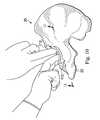
- FIG. 10is a diagrammatic perspective view of a step of securely implanting a prosthetic device into the prepared articular cartilage of a natural acetabulum according to one embodiment of the present disclosure.
- FIG. 12is a diagrammatic cross-sectional view of a stage of the prosthetic device being implanted into the prepared articular cartilage of the natural acetabulum similar to that of FIG. 11 , but showing a subsequent stage of implantation.
- FIG. 17is a diagrammatic cross-sectional view of a prosthetic device fully implanted into the prepared articular cartilage of a natural acetabulum and engaged with a femoral head according to one embodiment of the present disclosure.
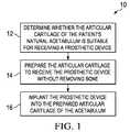
- the method 10begins at step 12 with the determination of whether the articular cartilage of a patient's natural acetabulum is suitable for receiving a prosthetic device in accordance with the present disclosure.
- the thickness and/or health of the articular cartilagemay be considered in determining whether the articular cartilage is suitable for receiving a prosthetic device.
- characteristics of the articular cartilageare determined pre-operatively using medical imaging. For example, in some instances MRI renderings of the patient's hip joint are utilized to determine the thickness and/or condition of the articular cartilage of the acetabulum.
- the thickness and/or condition of the articular cartilageis assessed using the methods and systems similar to those disclosed in U.S. Pat. No. 7,184,814 titled “ASSESSING THE CONDITION OF A JOINT AND ASSESSING CARTILAGE LOSS,” which is hereby incorporated by reference in its entirety. Further, in some embodiments the thickness and/or condition of the articular cartilage is confirmed during the surgical procedure itself to ensure that the articular cartilage is suitable for receiving the prosthetic device. In some instances, no pre-operative imaging of the articular cartilage is undertaken and the articular cartilage is evaluated only during the surgery.
- the thickness and/or condition of the articular cartilageis utilized to determine which of a library of prosthetic devices is capable or desirable for use with a specific patient. For example, in one specific example a first preferred prosthetic device requires a healthy articular cartilage thickness of at least 2.5 mm while a second preferred prosthetic device requires a healthy articular cartilage thickness of at least 1.5 mm. Accordingly, in some instances the thickness and health of the articular cartilage will dictate which of the first and second prosthetic devices is best suited for implantation into the patient's acetabulum.
- a patientmust have healthy articular cartilage with a thickness of at least 1.0 mm to be considered suitable for receiving a prosthetic device without causing damage to the underlying bone in accordance with the present disclosure. In some instances, a patient must have healthy articular cartilage with a thickness of at least 2.0 mm to be considered suitable for receiving a prosthetic device without causing damage to the underlying bone in accordance with the present disclosure.
- the prosthetic acetabular componentsinclude one or more projections extending from and outer engagement surface, where the maximum height of the projections from the engagement surface can be considered the projection height.
- the articular cartilagecan be evaluated to determine whether the cartilage has a thickness greater than or equal to the projection height. If the articular cartilage has a thickness greater than or equal to the projection height, then the articular cartilage is suitable for receiving the prosthetic device.
- the articular cartilagemay be suitable for receiving a prosthetic device with projections having a lower projection height.
- a prosthetic device with a plurality of projections having a lower projection heightis utilized.
- a surgeonmay decide to remove at least a minimal amount or volume of bone in addition to the articular cartilage.
- the projections of the prosthetic devicemay engage a portion of the bone while the substantial majority of the outer surface of the prosthetic device engages the articular cartilage of the patient.
- the projections of the deviceare particularly suited for engaging bone while the outer surface is engaged only with the articular cartilage.
- the prosthetic deviceincludes one or more engagement structures (e.g., projections and/or recesses) for engaging one or more prepared portions in the articular cartilage (e.g., recesses and/or projections). Accordingly, the portions of the articular cartilage positioned where the one or more prepared portions are to be formed are evaluated. Based on the characteristics of the articular cartilage where the prepared portions are to be formed, a determination of whether the articular cartilage is suitable for a particular prosthetic device can be made.
- engagement structurese.g., projections and/or recesses
- the method 10continues at step 14 with preparation of the articular cartilage of the natural acetabulum to receive the prosthetic device.
- preparation of the hip jointcomprises preparing a portion of the articular cartilage of the patient without damaging the underlying bony portion of the acetabulum.
- one or more recessesare created in the articular cartilage.
- each of the recessesmay be sized and shaped to engage a corresponding structural element of the prosthetic device that is to be inserted into the hip joint.
- the prosthetic deviceis similar to one or more of the prosthetic devices described in U.S. patent application Ser. No. 10/289,126 titled “ONE PIECE SNAP FIT ACETABULAR CUP,” U.S. patent application Ser. No. 10/497,897 titled “CUSHION BEARING IMPLANTS FOR LOAD BEARING APPLICATIONS,” U.S. patent application Ser. No. 10/515,486 titled “IMPLANTS,” U.S. patent application Ser. No.
- the articular cartilageis prepared to receive a snap-fit structure of the prosthetic device that is utilized to assist in securing the device within hip joint without penetrating bone.
- the articular cartilagemay be reamed, machined, cut, excised, compressed, and/or otherwise modified to include one or more recesses of various shapes and sizes to mate with corresponding snap-fit structure of a prosthetic device.
- the number, size, and shape of the recessesis dictated by the prosthetic device to be implanted.
- one or more surgical toolsare utilized to create the one or more recesses in the articular cartilage. In some instances, the tools are similar to those described in U.S. patent application Ser. No.
- FIGS. 2-5shown therein are various partial cross-sectional side views of a natural acetabulum 20 —comprised of an inner portion 22 formed of bone and an outer portion 24 formed of articular cartilage and generally having a thickness 26 —being prepared by a tool 30 according to one embodiment of the present disclosure.
- FIG. 2is a diagrammatic, partial cross-sectional side view of the tool 30 preparing the articular cartilage 24 of the natural acetabulum 20
- FIG. 3is a diagrammatic, partial cross-sectional side view of a stage subsequent to that of FIG. 2 of the tool 30 preparing the articular cartilage 24 of the natural acetabulum 20 ;
- FIG. 2is a diagrammatic, partial cross-sectional side view of a stage subsequent to that of FIG. 2 of the tool 30 preparing the articular cartilage 24 of the natural acetabulum 20 ;
- FIG. 2is a diagrammatic, partial cross-sectional side view of the tool 30 preparing the articular cartilage 24
- preparation of the articular cartilage 24 at step 14includes removing portions of the articular cartilage to define a substantially uniform surface prior to additional preparation of the articulating cartilage.
- the uniform surfaceis partially spherical. That is, the uniform surface is defined as a portion of an outer surface of a sphere. In some particular embodiments, the uniform surface is substantially semi-spherical. In that regard, the articular cartilage is reamed to create the uniform surface in some embodiments. In such instances the amount of cartilage removed is limited to that necessary to create the uniform surface. It is generally desirable to remove as little healthy articular cartilage as possible. However, in some instances it is desirable to remove damaged and/or unhealthy articular cartilage, which may require removal of some healthy cartilage as well to create the uniform surface. In other instances, the natural surface of the articular cartilage is utilized such that the surface is not necessarily uniform.
- the tool 30includes an anchoring element 32 having an outer surface 34 with a plurality of cartilage-engaging protrusions 36 extending therefrom.
- Each of the protrusions 36includes a rounded tip such that the protrusions can engage the articular cartilage 24 sufficiently to prevent unwanted movement of the tool 30 without causing damage to the articular cartilage surface.
- the protrusions 36are sized and shaped to temporarily deform the cartilage without penetrating or otherwise permanently altering the cartilage.
- the anchoring element 32Opposite the outer engagement surface 34 , the anchoring element 32 includes a recessed portion 37 .
- the tool 30also includes a central shaft 38 extending proximally along an axis 40 away from the anchoring element 32 towards a handle 42 .
- a rotational driving assembly 44including the handle 42 and an elongate hollow shaft 46 that is sized to rotationally accommodate central shaft 38 .
- the hollow shaft 46terminates in rotational driving plate 48 .
- a conical rotational and axial driving element 50Coupled to rotational driving plate 48 is a conical rotational and axial driving element 50 .
- the driving element 50threadingly engages the central shaft 38 .
- the rotational driving plate 48is formed with one or more pins 52 that extend into corresponding sockets 54 formed in driving element 50 that maintain the rotational driving plate 48 and the driving element 50 in axial alignment along the longitudinal axis 40 .
- a plurality of cutting elements 56are each slidably received within a pair of channels defined by the driving plate 48 and the driving element 50 .
- the cutting elementsare mounted on a resilient support ring 58 which permits simultaneous radially outward and rotational displacement of the cutting elements 56 in response to simultaneous axial and rotational movement of driving element 50 in threaded engagement with central shaft 38 in response to rotation of the handle 42 in a direction indicated by an arrow 60 .
- the tool 30also includes a radially displaceable cartilage engagement assembly 62 , typically comprises a plurality of integrally formed flexible engagement elements 64 , each comprising a hand engageable portion 66 lying between an proximal retaining portion 68 and a distal retaining portion 70 .
- the assembly 62also includes a radially expandable cartilage engaging portions 72 .
- the assembly 62includes six integrally formed flexible engagement elements 64 that are held together about hollow shaft 46 at the retaining portions 68 and 70 .
- an operatorsuch as a surgeon, grasping second handle hand engageable portion 66 with one hand causes inward bending of flexible engagement elements 64 , which causes cartilage engaging portions 72 to be displaced radially outwardly into retaining engagement with the walls of the articular cartilage being prepared.
- the assembly 62may be used in addition to or in lieu of the anchoring element 32 to prevent unwanted movement of the tool 30 during preparation of the articular cartilage.
- the anchoring element 32does not include projections 36 such that anchoring element alone may be insufficient to prevent unwanted movement of the tool 30 .
- the assembly 62is utilized to stabilize the tool 30 during preparation of the articular cartilage.
- the cartilage engaging portions 72 of the assembly 62have been extended radially to engage side surfaces of the articular cartilage 24 .
- This engagementis produced by the surgeon or other medical professional squeezing the hand engageable portion 66 inward as indicated by arrows 76 , producing corresponding radially outward displacement of cartilage engaging portions 72 into retaining engagement with the side surfaces of the articular cartilage 24 .
- Thisfurther stabilizes the tool 30 and resists unwanted movement with respect to the acetabulum 20 .
- FIG. 4shown therein is the beginning of a reaming operation for creating an annular recess in the articular cartilage 24 .
- Rotation of the handle 42 about axis 40such as in a direction indicated by arrows 78 causes a similar rotation of driving element 50 about axis 40 , which results in axial displacement distally of driving element 50 due to its threaded engagement with central shaft 38 .
- This distal displacement of driving element 50urges the cutting elements 56 , which are slidably seated in the channels of the driving element 50 and the driving plate 48 , in a radially outward direction, as indicated by arrows 80 , into cutting engagement with the articular cartilage 24 .
- FIG. 5shown therein is a substantially completed reaming operation produced by rotation of the handle 42 about axis 40 .
- Continued rotation of the handle 42causes rotation of the driving element 50 about axis 40 and corresponding distal axial displacement of the driving element 50 due to the threaded engagement with the central shaft 38 as discussed above.
- the cutting elements 56are urged further radially outward.
- the axial displacement of the driving element 50typically stops when the driving element 50 engages the bottom of the recessed portion 37 formed in the anchoring element 32 opposite the engagement surface 34 . At this point the cutting elements 56 are at a maximum radial displacement.
- the maximum radial displacement of the cutting elements 56corresponds with a desired depth of the annular recess being formed in the articular cartilage 24 .
- the cutting elements 56are configured to be displaced radially such that a recess having a depth between about 0.5 mm and about 2.0 mm is created in the articular cartilage.
- the cutting elements 56are displaced to a lesser or greater extent.
- the depth of the recessed portion 37 of the anchoring element 32 , the angle of the conical aspect of the driving element 50 , and/or other aspects of the toolare sized to create a desired maximum outward radial displacement of the cutting elements 56 .
- the maximum outward radial displacement of the cutting elements 56is adjustable such that a surgeon can select the maximum displacement corresponding to a prosthetic device that is to be implanted.
- the maximum outward radial displacement of the cutting elementsis set such that the radius of the cutting elements as measured from axis 40 is less than the spherical radius of the boundary between the bone and the articular cartilage, such that even at maximum displacement the cutting elements will not reach the bone. In this manner, accidental or unintended removal of bone is limited.
- one or more sizing cupsare utilized to set the maximum displacement of the cutting elements 56 .
- the sizing cupsare generally made of material sufficiently hard to prevent penetration by the cutting elements.
- cutting elementsare extended outwardly until they contact the sizing cup at which point the maximum displacement of the cutting elements is set.
- the particular sizing cup chosenis based on the patient's anatomy as determined using imaging techniques or otherwise.
- a plurality of tools 30 having different maximum radial displacementsare provided.
- the tools 30have a radial displacement of the cutting elements that is associated with a particular prosthetic device, such that a particular tool is to be used with a particular device.
- the extension and retraction of cutting elements 56may be monitored by a gauging apparatus that is viewable by the operator of the tool 30 .
- the gauging apparatusmay be mechanical or electronic.
- control of the tool 30may at least partially be computer guided or aided. Further still, rotation of elongate hollow shaft 46 and driving plate 50 may be controlled or actuated by an electronic or hydraulic system, and the operator may utilize the display of extension and retraction of the cutting elements to determine the completion of annular recess to a precise desired depth. In this manner, the electronic or hydraulic system may replace handle 42 . In other instances, the preparation may be performed substantially by the tool 30 being controlled by a computer system.
- FIGS. 6 and 7shown therein is the natural acetabulum 20 —comprised of the inner portion 22 formed of bone and the outer portion 24 formed of articular cartilage and generally having the thickness 26 —being prepared by a tool 90 according to another embodiment of the present disclosure.
- FIG. 6is a diagrammatic perspective view of the tool 90 preparing the articular cartilage 24 of the natural acetabulum 20
- FIG. 7is a diagrammatic, partial cross-sectional side view of FIG. 6 .
- the tool 90is provided with a handle 92 fixedly coupled to a shaft 94 .
- An elongate gripping portion 96is rotatably and slidably mounted over shaft 94 and axially engages a plurality of outwardly extendible engagement elements 98 , which are also rotatably and slidably mounted with respect to shaft 94 .
- the outwardly extendible engagement elements 98are spaced by a plurality of axially extending slots 100 .
- the outwardly extendible engagement elements 98include engagement features 102 extending from distal portions of the elements 98 .
- the engagement features 102are for engaging the articular cartilage after outward displacement of the elements 98 .
- the engagement features 102are sized and shaped to engage the articular cartilage without causing permanent damage to the articular cartilage.
- the engagement featurescomprise a roughened surface (e.g., knurled, grit blasted, diamond patterned, or otherwise) for frictionally engaging the articular cartilage.
- the outwardly extendable engagement elements 98are displaced radially outward upon axial movement in a distal direction. In that regard, the axial movement of the engagement elements 98 is directly controlled by the position of the gripping portion 96 in some instances.
- the gripping portion 96 and the engagement elements 98are integrally formed.
- the anchoring mechanism 104is generally disc shaped and includes a plurality of engagement features 106 extending distally.
- the engagement features 106are configured to engage the bony portions of the acetabulum 20 positioned surrounding the socket defined by the articular cartilage 24 .
- the engagement features 106are spikes for penetrating the bone in some instances. In other embodiments, the engagement features 106 comprise other types of protrusions for engaging the bone.
- the anchoring mechanism 104is moveable axially and rotationally relative to the shaft 94 .
- the anchoring mechanism 104is connected or integral to the distal portions of engagement elements 98 such that the anchoring mechanism is axially displaced along with the engagement elements. In some such embodiments, the anchoring mechanism 104 does not extend outwardly along with engagement elements, but rather has fixed dimensions relative to the shaft 94 . Using the anchoring mechanism 104 , the tool 90 can be securely engaged to the acetabulum to prevent unwanted movement of the tool 90 without damaging the articular cartilage 24 that will receive the prosthetic device.
- the anchoring mechanism 104is the primary anchoring or stabilizing feature of the tool 90 .
- the number of engagement features 106 extending from the anchoring mechanism 104varies.
- the anchoring mechanism 104includes any where from 1 to 12 engagement features 106 .
- the anchoring mechanism 104includes additional engagement features.
- the method 10continues at step 16 with implanting the prosthetic device into the prepared articular cartilage 24 of the acetabulum.
- the methods of the present disclosurehelp to preserve as much of the natural bone structure of the patient's natural acetabulum 20 as possible.
- one or more recessesmay be created in the articular cartilage and, in some instances, may be sized and shaped to engage a corresponding structural element of the prosthetic device is similar to one or more of the prosthetic devices described in U.S. patent application Ser. No.
- the prosthetic acetabular cupincludes a substantially smooth and continuous engaging surface.
- the articular cartilageis prepared with projections and/or recesses, such that after implantation the engaging surface of the prosthetic acetabular cup adapts to the projections and/or recesses of the articular cartilage to secure the prosthetic acetabular cup within the hip joint.
- at least the engaging surface of the prosthetic acetabular cupdeforms to securely engage the projections and/or recesses of the articular cartilage without changing the geometry of the inner articulating surface of the prosthetic acetabular cup.
- At least the engaging surface of the prosthetic acetabular cupdeforms to securely engage the projections and/or recesses of the articular cartilage without changing the geometry of the inner articulating surface or adjacent portions of the prosthetic acetabular cup.
- at least an area having a thickness between about 0.5 mm and about 1.0 mm adjacent the inner articulating surfaceis not affected by deformation of the outer portion of the device.
- deformation of the prosthetic acetabular cupoccurs immediately upon implantation of the device.
- the engaging surface of the prosthetic acetabular cupflexibly deforms to substantially match the protrusions and/or recesses of the articular cartilage upon implantation (e.g., minutes, hours, or days) and the inner portions of the device adjacent the engaging surface adjust to the modified shape over an extended period of time (e.g., weeks or months).
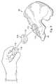
- FIG. 8shown therein is a perspective series view of the introduction and pre-snap-fit placement of an implantable prosthetic acetabular socket 110 into the prepared acetabulum 20 according to one aspect of the present disclosure.
- the prosthetic acetabular socket 110includes a snap-fit structure 112 on an outer surface.
- the snap-fit structure 112comprises an annular protrusion extending around a perimeter of the socket 110 between the rim and the apex of the socket that is configured to snap-fit into engagement with the recess prepared in the articular cartilage 24 of the acetabulum 20 .
- FIG. 9shown therein is a perspective series view of the introduction and pre-snap-fit placement of the implantable prosthetic acetabular socket 110 into the prepared acetabulum 20 according to another aspect of the present disclosure.
- the acetabular socket 110is introduced in a folded configuration.
- a flexible and breakable band 114is utilized in some instances to maintain the acetabular socket 110 in the folded configuration during insertion.
- the band 114is removed and the resiliency of the acetabular socket 110 causes the socket to return to its natural configuration.
- the acetabular socket 110is maintained in the folded configuration by the surgeon's hand, a tool, or otherwise.
- the resultant positioning of the socket 110is the same in both FIGS. 8 and 9 .
- Use of the folded configuration as shown in FIG. 9is particularly suitable for minimally invasive surgical approaches.
- FIG. 10is a diagrammatic perspective view of a step of securely implanting the prosthetic acetabular socket 110 into the prepared articular cartilage 24 of the natural acetabulum 20 ;
- FIG. 11is a diagrammatic cross-sectional view of a stage of the prosthetic acetabular socket 110 being implanted into the prepared articular cartilage 24 ;
- FIG. 12is a diagrammatic cross-sectional view of a stage of the prosthetic acetabular socket 110 being implanted into the prepared articular cartilage 24 similar to that of FIG.
- FIG. 13is a diagrammatic cross-sectional view of a stage of the prosthetic acetabular socket 110 being implanted into the prepared articular cartilage 24 similar to that of FIGS. 11 and 12 , but showing a subsequent stage of implantation
- FIG. 14is a diagrammatic perspective view of a step of securely implanting a prosthetic acetabular socket 110 into the prepared articular cartilage 24 similar to that of FIG. 10 , but showing a subsequent step
- FIG. 15is a diagrammatic cross-sectional view of a stage of the prosthetic acetabular socket 110 being implanted into the prepared articular cartilage 24 similar to that of FIGS. 11 , 12 , and 13 , but showing the device fully implanted into the prepared articular cartilage.
- FIG. 10following introduction and placement of the implantable artificial acetabular socket 110 adjacent the prepared acetabulum 20 , a surgeon, using his fingers, gently begins urging the artificial acetabular socket 110 into position for snap-fit engagement with the articular cartilage 24 .
- This positionis shown clearly in the cross-sectional view of FIG. 11 , which is a cross-sectional illustration of the orientation of FIG. 10 .
- the annular snap-fit protrusion 112lies in touching, generally non-compressive engagement with an outer portion of a concave surface 120 of the articular cartilage 24 .
- the outer portion of the concave surface 120lies above the recess 122 formed in the articular cartilage 24 during preparation of the acetabulum 20 .
- the recess 122is generally annular extending around the concave surface 120 .
- the recess 122is sized, shaped, and positioned for snap-fit engagement with the annular protrusion 112 of the prosthetic acetabular socket 110 . Accordingly, initial engagement of the protrusion 112 with the outer portion of the concave surface 120 causes the implantable artificial acetabular socket 110 to rest at a position such that the rim or outer edge of the socket 110 lies above a corresponding outer edge of prepared acetabulum 20 .
- the separation between the outer edges of the implantable artificial acetabular socket 110 and the acetabulum 20 , along axis 123is indicated by distance 124 .
- the prosthetic acetabular socket 110has been further urged towards snap-fit engagement with the articular cartilage 24 .
- the surgeon or other medical professionaluses his fingers to gently engage the inner concave surface of the artificial acetabular socket 110 and presses thereon in a direction indicated by arrows 126 , which direction lies generally along axis 123 .
- the application of this pressurecauses displacement of artificial acetabular socket 110 in the direction 126 .
- Due to the concave configuration of the outer portion of concave surface 120this displacement produces radially inward compression of artificial acetabular socket 110 at annular protrusion 112 , as indicated by arrows 128 .
- the prosthetic acetabular socket 110has been further urged towards snap-fit engagement with the articular cartilage 24 .
- the surgeon or other medical professionaluses his fingers to gently engage the inner concave surface of the artificial acetabular socket 110 and further presses thereon in a direction indicated by arrows 126 , which direction lies generally along axis 123 .
- the application of this pressurecauses displacement of artificial acetabular socket 110 in the direction 126 .
- This further displacementproduces sliding pressure engagement between underlying surface portion of the annular protrusion 112 and the concave surface 120 until the protrusion 112 reaches the recess 122 .
- the resiliency of the artificial acetabular socket 110causes radially outward displacement of protrusion 112 once the protrusion reaches the recess 122
- this further displacement of artificial acetabular socket 110 in direction 126further reduces the separation between the outer edges of implantable artificial acetabular socket 110 and the acetabulum 20 as indicated by distance 132 , which is less than the distances 130 and 124 of FIGS. 11 and 10 respectively.
- engagement of the protrusion 112 with the concave surface 120causes the prosthetic device 110 to deform.
- the prosthetic device 110including its outer and inner surfaces are deformed inwardly such that the outer and inner surface are not substantially, partially spherical. Instead, the outer and inner surfaces become partially elliptical or oblonged.
- the bottom portion of the outer surface as viewed in FIG. 13is closer to the concave surface 120 than the side portions of the outer surface.
- the prosthetic acetabular socket 110is urged into complete snap-fit engagement with the articular cartilage 24 .
- the surgeonusing his fingers, presses on the artificial acetabular socket 110 in direction 126 .
- the surgeonpresses on the rim of the socket 110 at this stage to urged the socket into complete engagement with the acetabulum 20 .
- the application of this further pressurecauses further displacement of artificial acetabular socket 110 in direction 126 . This further displacement produces the resultant sliding snap-fit engagement between protrusion 112 and recess 122 .
- the snap-fit engagement of the artificial acetabular socket 110 with the prepared articular cartilage 24produces locking of the artificial acetabular socket 110 relative to the acetabulum 20 without damaging the underlying bone structure of the acetabulum.
- the outer edge of the socket 110may extend beyond the outer edge of the acetabulum, as indicated by distance 134 , in some embodiments. In other embodiments, however, the outer edge of the socket 110 is substantially aligned with or below the outer edge of the acetabulum.
- the acetabular socket 110generally has a width or thickness 136 (excluding protrusion 112 ).
- the thickness 136is generally between about 0.5 mm and about 6.0 mm.
- the articular cartilage 24has a thickness 26 , which is generally less than about 4.0 mm. Accordingly, the thickness 136 of the socket 110 may be less than, equal to, or greater than the thickness 26 of the articular cartilage 24 .
- the distance 138is between about 2.0 mm and about 10.0 mm.
- the specific combined thicknessis determined based on a femoral head (natural or artificial) that is to be mated with the socket 110 .
- the projections and/or recesses of the prosthetic devices and the projections and/or recesses formed in the articular cartilagegenerally have thickness between about 0.5 mm and about 2.5 mm. Accordingly, the individual thicknesses of the prosthetic device and the prepared articular cartilage may vary up to 2.5 mm, while the combined thickness remains substantially constant.
- the thickness 26 of the articular cartilage 26is approximately 3.0 mm
- the thickness 136 of the socket 110is approximately 4.0 mm
- the protrusion 112 and recess 122have a respective height and depth of approximately 2.0 mm.
- FIG. 16shown therein is a diagrammatic cross-sectional view of a prosthetic device 150 fully implanted into prepared articular cartilage 24 of the natural acetabulum 20 similar to that of FIG. 15 , but showing an alternative embodiment of the present disclosure.
- the prosthetic device 150includes a pair of annular recesses formed therein 152 , 154 .
- the annular recesses 152 , 154may be continuous about the circumference of the device 150 or defined by a plurality of discrete recess portions. As shown, the recesses 152 , 154 are spaced from one another between the apex of the device 150 and the rim of the device.
- the articular cartilage 24has been prepared to form a pair of annular protrusions 156 , 158 extending therefrom.
- the protrusions 156 , 158are sized and shaped for snap-fit engagement with the annular recesses 152 , 154 of the device 150 .
- the protrusions 156 , 158may also be continuous or discrete.
- the device 150 and cartilage 24are shown as having 2 recesses and protrusions, respectively, in other embodiments they may include additional recesses and protrusions. In that regard, in some embodiments a plurality of interlocking recesses and protrusions are utilized to secure the device 150 to the cartilage 24 .
- using a plurality of recesses and protrusionsallows for the depth of the recesses and height of the protrusions to be less, such that the prosthetic device can be used with a patient with minimal healthy articular cartilage.
- a patient with at least 0.5 mm of healthy articular cartilagecan receive a prosthetic device having a plurality of projections and/or recesses in accordance with the present disclosure.
- the device 150includes protrusions and the cartilage 24 is prepared to include recesses.
- each of the device 150 and the cartilage 24may include both at least one projection and at least one recess in some instances.
- the device 150includes a rounded outer rim or edge as shown.
- a protrusion at least partially matching that curvature of the outer rimis formed in the articular cartilage to further secure the device in place.
- the articular cartilageis also rounded as shown in FIG. 16 .
- the device 150includes substantially as seen in other embodiments of the present disclosure.
- the othermay include a rounded outer rim or edge as shown in FIG. 16 .
- the engagement surface of the prosthetic devicesmay be treated to enhance engagement between the articular cartilage and the device.
- the engagement surface of the deviceis roughened to increase the friction between the articular cartilage and the device.
- the friction between the articular cartilage and the prosthetic deviceis greater than the friction between the prosthetic device and the femoral head (artificial or natural) received by the prosthetic device, such that articulation of the femoral head with respect to the device does impart movement upon the prosthetic device relative to the articular cartilage.
- the engagement surfacemay be treated with biologics to encourage ingrowth of articular cartilage.
- the engagement surfacereceives one or more surface treatments as described in U.S. patent application Ser. No. 10/497,897 titled “CUSHION BEARING IMPLANTS FOR LOAD BEARING APPLICATIONS,” hereby incorporated by reference in its entirety.
- a femoral head 140is mated with a prosthetic device—the acetabular socket 110 is illustrated—that has been fully implanted into the prepared acetabulum.
- the femoral headmay be either a natural or artificial femoral head.
- the bonemay be prepared to include a radius of curvature substantially matching that of the inner articulating surface of the prosthetic device.
- the at least the outer surface of the prosthetic deviceis wetted prior to implantation into the prepared acetabulum.
- the prosthetic deviceis saturated prior to implantation into the prepared acetabulum.
- the prosthetic deviceis made of a water-absorbent polymer that is hydrated prior to implantation. Wetting and/or saturating the prosthetic device prior to implantation can both lubricate the device making it easier to insert as well as increase the locking engagement of the prosthetic device with the articular cartilage once the device is seated within the articular cartilage by creating a fluid adhesion bond or fluid lock between the articular cartilage and the prosthetic device.
- the fluid adhesion bond between the articular cartilage and the prosthetic deviceis sufficient to prevent unwanted disengagement of the device from the acetabulum in a direction opposite insertion direction 126 , as shown in FIGS. 12 and 13 for example.
- the fluid adhesion bonddoes not necessarily prevent rotational movement of the device relative to the articular cartilage, but instead prevents unwanted separation of the device from the prepared articular cartilage.
- the fluid adhesion bondis combined with the snap-fit interface described above to increase the engagement.
- the snap-fit interfaceis configured to prevent unwanted rotation of the prosthetic device relative to the articular cartilage, while the fluid adhesion bond prevents axial displacement of the prosthetic device relative to the acetabulum.
- the fluid used to wet or saturate the devicemay be saline solution or other suitable biocompatible liquid for creating the fluid lock.
- a layer of fluid 186is positioned between the prosthetic acetabular cup 110 and the articular cartilage 24 and creates a liquid adhesion bond therebetween.
- creation of the liquid adhesion bondis dependent on the surface of the device substantially matching the geometry of the prepared surface of the articular cartilage. Accordingly, in some embodiments, the deformation of the outer portion or surface of the device over time or “creep” of the device causes the outer surface of the device to better match the articular cartilage over time. Accordingly, in some instances, the device is not subjected to a liquid adhesion bond immediately upon implantation but obtains a liquid adhesion bond over time. In some instances, synovial fluid of the hip joint is introduced and/or migrates between the device and the articular cartilage over time to create and/or enhance the fluid adhesion bond.
- the prosthetic devices of the present disclosureare fiber reinforced, include a deformation control element, or comprise a material or combination of materials particularly suited for positioning within an articulating joint.
- the prosthetic devicesare formed of materials or combinations of materials as described in U.S. patent application Ser. No. 10/497,897 titled “CUSHION BEARING IMPLANTS FOR LOAD BEARING APPLICATIONS” and U.S. patent application Ser. No. 12/100,090 titled “MANUFACTURING AND MATERIAL PROCESSING FOR PROSTHETIC DEVICES”, each hereby incorporated by reference in its entirety.
Landscapes
- Health & Medical Sciences (AREA)
- Orthopedic Medicine & Surgery (AREA)
- Life Sciences & Earth Sciences (AREA)
- Animal Behavior & Ethology (AREA)
- Veterinary Medicine (AREA)
- Public Health (AREA)
- Oral & Maxillofacial Surgery (AREA)
- Engineering & Computer Science (AREA)
- Biomedical Technology (AREA)
- Heart & Thoracic Surgery (AREA)
- General Health & Medical Sciences (AREA)
- Transplantation (AREA)
- Vascular Medicine (AREA)
- Cardiology (AREA)
- Surgery (AREA)
- Rheumatology (AREA)
- Dentistry (AREA)
- Nuclear Medicine, Radiotherapy & Molecular Imaging (AREA)
- Medical Informatics (AREA)
- Molecular Biology (AREA)
- Prostheses (AREA)
Abstract
Description
Claims (20)
Priority Applications (1)
| Application Number | Priority Date | Filing Date | Title |
|---|---|---|---|
| US12/124,709US7780740B2 (en) | 2007-05-21 | 2008-05-21 | Methods, systems, and apparatus for implanting prosthetic devices into cartilage |
Applications Claiming Priority (2)
| Application Number | Priority Date | Filing Date | Title |
|---|---|---|---|
| US93932307P | 2007-05-21 | 2007-05-21 | |
| US12/124,709US7780740B2 (en) | 2007-05-21 | 2008-05-21 | Methods, systems, and apparatus for implanting prosthetic devices into cartilage |
Publications (2)
| Publication Number | Publication Date |
|---|---|
| US20080294266A1 US20080294266A1 (en) | 2008-11-27 |
| US7780740B2true US7780740B2 (en) | 2010-08-24 |
Family
ID=40073156
Family Applications (1)
| Application Number | Title | Priority Date | Filing Date |
|---|---|---|---|
| US12/124,709Active2029-03-18US7780740B2 (en) | 2007-05-21 | 2008-05-21 | Methods, systems, and apparatus for implanting prosthetic devices into cartilage |
Country Status (1)
| Country | Link |
|---|---|
| US (1) | US7780740B2 (en) |
Cited By (71)
| Publication number | Priority date | Publication date | Assignee | Title |
|---|---|---|---|---|
| US20090287311A1 (en)* | 2006-08-04 | 2009-11-19 | Roman Preuss | Asymmetric design of hip socket for reducing socket deformations |
| US20100152782A1 (en)* | 2006-02-27 | 2010-06-17 | Biomet Manufactring Corp. | Patient Specific High Tibia Osteotomy |
| US20100324692A1 (en)* | 2007-04-17 | 2010-12-23 | Biomet Manufacturing Corp. | Method and Apparatus for Manufacturing an Implant |
| US8377066B2 (en) | 2006-02-27 | 2013-02-19 | Biomet Manufacturing Corp. | Patient-specific elbow guides and associated methods |
| US8398646B2 (en) | 2006-06-09 | 2013-03-19 | Biomet Manufacturing Corp. | Patient-specific knee alignment guide and associated method |
| US8473305B2 (en) | 2007-04-17 | 2013-06-25 | Biomet Manufacturing Corp. | Method and apparatus for manufacturing an implant |
| US8486150B2 (en) | 2007-04-17 | 2013-07-16 | Biomet Manufacturing Corp. | Patient-modified implant |
| US8532807B2 (en) | 2011-06-06 | 2013-09-10 | Biomet Manufacturing, Llc | Pre-operative planning and manufacturing method for orthopedic procedure |
| US8535387B2 (en) | 2006-02-27 | 2013-09-17 | Biomet Manufacturing, Llc | Patient-specific tools and implants |
| US8568487B2 (en) | 2006-02-27 | 2013-10-29 | Biomet Manufacturing, Llc | Patient-specific hip joint devices |
| US8591516B2 (en) | 2006-02-27 | 2013-11-26 | Biomet Manufacturing, Llc | Patient-specific orthopedic instruments |
| US8597365B2 (en) | 2011-08-04 | 2013-12-03 | Biomet Manufacturing, Llc | Patient-specific pelvic implants for acetabular reconstruction |
| US8603180B2 (en) | 2006-02-27 | 2013-12-10 | Biomet Manufacturing, Llc | Patient-specific acetabular alignment guides |
| US8608748B2 (en) | 2006-02-27 | 2013-12-17 | Biomet Manufacturing, Llc | Patient specific guides |
| US8608749B2 (en) | 2006-02-27 | 2013-12-17 | Biomet Manufacturing, Llc | Patient-specific acetabular guides and associated instruments |
| US8632547B2 (en) | 2010-02-26 | 2014-01-21 | Biomet Sports Medicine, Llc | Patient-specific osteotomy devices and methods |
| US8668700B2 (en) | 2011-04-29 | 2014-03-11 | Biomet Manufacturing, Llc | Patient-specific convertible guides |
| US8715289B2 (en) | 2011-04-15 | 2014-05-06 | Biomet Manufacturing, Llc | Patient-specific numerically controlled instrument |
| US8764760B2 (en) | 2011-07-01 | 2014-07-01 | Biomet Manufacturing, Llc | Patient-specific bone-cutting guidance instruments and methods |
| WO2014074804A3 (en)* | 2012-11-08 | 2014-10-09 | Smith & Nephew, Inc. | Methods and compositions suitable for improved reattachment of detached cartilage to subchondral bone |
| US8858561B2 (en) | 2006-06-09 | 2014-10-14 | Blomet Manufacturing, LLC | Patient-specific alignment guide |
| US8864769B2 (en) | 2006-02-27 | 2014-10-21 | Biomet Manufacturing, Llc | Alignment guides with patient-specific anchoring elements |
| US8900244B2 (en) | 2006-02-27 | 2014-12-02 | Biomet Manufacturing, Llc | Patient-specific acetabular guide and method |
| US8956364B2 (en) | 2011-04-29 | 2015-02-17 | Biomet Manufacturing, Llc | Patient-specific partial knee guides and other instruments |
| US9060788B2 (en) | 2012-12-11 | 2015-06-23 | Biomet Manufacturing, Llc | Patient-specific acetabular guide for anterior approach |
| US9066734B2 (en) | 2011-08-31 | 2015-06-30 | Biomet Manufacturing, Llc | Patient-specific sacroiliac guides and associated methods |
| US9084618B2 (en) | 2011-06-13 | 2015-07-21 | Biomet Manufacturing, Llc | Drill guides for confirming alignment of patient-specific alignment guides |
| US9113971B2 (en) | 2006-02-27 | 2015-08-25 | Biomet Manufacturing, Llc | Femoral acetabular impingement guide |
| US9173661B2 (en) | 2006-02-27 | 2015-11-03 | Biomet Manufacturing, Llc | Patient specific alignment guide with cutting surface and laser indicator |
| US9204977B2 (en) | 2012-12-11 | 2015-12-08 | Biomet Manufacturing, Llc | Patient-specific acetabular guide for anterior approach |
| US9237950B2 (en) | 2012-02-02 | 2016-01-19 | Biomet Manufacturing, Llc | Implant with patient-specific porous structure |
| US9241745B2 (en) | 2011-03-07 | 2016-01-26 | Biomet Manufacturing, Llc | Patient-specific femoral version guide |
| US9271744B2 (en) | 2010-09-29 | 2016-03-01 | Biomet Manufacturing, Llc | Patient-specific guide for partial acetabular socket replacement |
| US9289253B2 (en) | 2006-02-27 | 2016-03-22 | Biomet Manufacturing, Llc | Patient-specific shoulder guide |
| US9295497B2 (en) | 2011-08-31 | 2016-03-29 | Biomet Manufacturing, Llc | Patient-specific sacroiliac and pedicle guides |
| US9301812B2 (en) | 2011-10-27 | 2016-04-05 | Biomet Manufacturing, Llc | Methods for patient-specific shoulder arthroplasty |
| US9339278B2 (en) | 2006-02-27 | 2016-05-17 | Biomet Manufacturing, Llc | Patient-specific acetabular guides and associated instruments |
| US9345548B2 (en) | 2006-02-27 | 2016-05-24 | Biomet Manufacturing, Llc | Patient-specific pre-operative planning |
| US9351743B2 (en) | 2011-10-27 | 2016-05-31 | Biomet Manufacturing, Llc | Patient-specific glenoid guides |
| US9386993B2 (en) | 2011-09-29 | 2016-07-12 | Biomet Manufacturing, Llc | Patient-specific femoroacetabular impingement instruments and methods |
| US9393028B2 (en) | 2009-08-13 | 2016-07-19 | Biomet Manufacturing, Llc | Device for the resection of bones, method for producing such a device, endoprosthesis suited for this purpose and method for producing such an endoprosthesis |
| US9408616B2 (en) | 2014-05-12 | 2016-08-09 | Biomet Manufacturing, Llc | Humeral cut guide |
| US9451973B2 (en) | 2011-10-27 | 2016-09-27 | Biomet Manufacturing, Llc | Patient specific glenoid guide |
| US9498233B2 (en) | 2013-03-13 | 2016-11-22 | Biomet Manufacturing, Llc. | Universal acetabular guide and associated hardware |
| US9517145B2 (en) | 2013-03-15 | 2016-12-13 | Biomet Manufacturing, Llc | Guide alignment system and method |
| US9554910B2 (en) | 2011-10-27 | 2017-01-31 | Biomet Manufacturing, Llc | Patient-specific glenoid guide and implants |
| US9561040B2 (en) | 2014-06-03 | 2017-02-07 | Biomet Manufacturing, Llc | Patient-specific glenoid depth control |
| US9579107B2 (en) | 2013-03-12 | 2017-02-28 | Biomet Manufacturing, Llc | Multi-point fit for patient specific guide |
| US9675400B2 (en) | 2011-04-19 | 2017-06-13 | Biomet Manufacturing, Llc | Patient-specific fracture fixation instrumentation and method |
| US20170181857A1 (en)* | 2015-12-29 | 2017-06-29 | Metal Industries Research & Development Centre | Acetabular cup structure |
| US9795399B2 (en) | 2006-06-09 | 2017-10-24 | Biomet Manufacturing, Llc | Patient-specific knee alignment guide and associated method |
| US9820868B2 (en) | 2015-03-30 | 2017-11-21 | Biomet Manufacturing, Llc | Method and apparatus for a pin apparatus |
| US9826981B2 (en) | 2013-03-13 | 2017-11-28 | Biomet Manufacturing, Llc | Tangential fit of patient-specific guides |
| US9826994B2 (en) | 2014-09-29 | 2017-11-28 | Biomet Manufacturing, Llc | Adjustable glenoid pin insertion guide |
| US9833245B2 (en) | 2014-09-29 | 2017-12-05 | Biomet Sports Medicine, Llc | Tibial tubercule osteotomy |
| US9839438B2 (en) | 2013-03-11 | 2017-12-12 | Biomet Manufacturing, Llc | Patient-specific glenoid guide with a reusable guide holder |
| US9839436B2 (en) | 2014-06-03 | 2017-12-12 | Biomet Manufacturing, Llc | Patient-specific glenoid depth control |
| US9907659B2 (en) | 2007-04-17 | 2018-03-06 | Biomet Manufacturing, Llc | Method and apparatus for manufacturing an implant |
| US9918740B2 (en) | 2006-02-27 | 2018-03-20 | Biomet Manufacturing, Llc | Backup surgical instrument system and method |
| US9968376B2 (en) | 2010-11-29 | 2018-05-15 | Biomet Manufacturing, Llc | Patient-specific orthopedic instruments |
| US10058352B2 (en) | 2012-11-08 | 2018-08-28 | Smith & Nephew, Inc. | Methods and devices suitable for improved reattachment of detached cartilage to subchondral bone |
| US10226262B2 (en) | 2015-06-25 | 2019-03-12 | Biomet Manufacturing, Llc | Patient-specific humeral guide designs |
| US10278711B2 (en) | 2006-02-27 | 2019-05-07 | Biomet Manufacturing, Llc | Patient-specific femoral guide |
| US10282488B2 (en) | 2014-04-25 | 2019-05-07 | Biomet Manufacturing, Llc | HTO guide with optional guided ACL/PCL tunnels |
| US10492798B2 (en) | 2011-07-01 | 2019-12-03 | Biomet Manufacturing, Llc | Backup kit for a patient-specific arthroplasty kit assembly |
| US10568647B2 (en) | 2015-06-25 | 2020-02-25 | Biomet Manufacturing, Llc | Patient-specific humeral guide designs |
| US10603179B2 (en) | 2006-02-27 | 2020-03-31 | Biomet Manufacturing, Llc | Patient-specific augments |
| US10722310B2 (en) | 2017-03-13 | 2020-07-28 | Zimmer Biomet CMF and Thoracic, LLC | Virtual surgery planning system and method |
| US11179165B2 (en) | 2013-10-21 | 2021-11-23 | Biomet Manufacturing, Llc | Ligament guide registration |
| US11419618B2 (en) | 2011-10-27 | 2022-08-23 | Biomet Manufacturing, Llc | Patient-specific glenoid guides |
| US12059354B2 (en)* | 2019-02-15 | 2024-08-13 | Howmedica Osteonics Corp. | Robotic acetabulum preparation for acceptance of acetabular cup with engagement features |
Families Citing this family (15)
| Publication number | Priority date | Publication date | Assignee | Title |
|---|---|---|---|---|
| US8070752B2 (en) | 2006-02-27 | 2011-12-06 | Biomet Manufacturing Corp. | Patient specific alignment guide and inter-operative adjustment |
| US8298237B2 (en) | 2006-06-09 | 2012-10-30 | Biomet Manufacturing Corp. | Patient-specific alignment guide for multiple incisions |
| US8282646B2 (en) | 2006-02-27 | 2012-10-09 | Biomet Manufacturing Corp. | Patient specific knee alignment guide and associated method |
| US8265949B2 (en) | 2007-09-27 | 2012-09-11 | Depuy Products, Inc. | Customized patient surgical plan |
| EP2194889B1 (en) | 2007-09-30 | 2015-09-23 | DePuy Products, Inc. | Customized patient-specific orthopaedic surgical instrumentation |
| US8357111B2 (en) | 2007-09-30 | 2013-01-22 | Depuy Products, Inc. | Method and system for designing patient-specific orthopaedic surgical instruments |
| US8170641B2 (en) | 2009-02-20 | 2012-05-01 | Biomet Manufacturing Corp. | Method of imaging an extremity of a patient |
| US9066727B2 (en) | 2010-03-04 | 2015-06-30 | Materialise Nv | Patient-specific computed tomography guides |
| US20170319348A1 (en) | 2015-08-10 | 2017-11-09 | Catalyst Orthoscience Inc. | Arthroplasty prostheses with multi-axis fixation |
| US10973646B2 (en) | 2013-03-11 | 2021-04-13 | Catalyst Orthoscience Inc. | Stabilized drill guide |
| US11007063B2 (en)* | 2013-03-11 | 2021-05-18 | Catalyst Orthoscience Inc. | Offset reamers |
| US11051829B2 (en) | 2018-06-26 | 2021-07-06 | DePuy Synthes Products, Inc. | Customized patient-specific orthopaedic surgical instrument |
| CN109172056B (en)* | 2018-09-06 | 2023-11-14 | 北京市春立正达医疗器械股份有限公司 | Press fitting tool for reverse shoulder joint prosthesis |
| EP3685805B1 (en) | 2019-01-25 | 2021-10-06 | Howmedica Osteonics Corp. | Cemented acetabular construct with locked modular sleeve |
| CN110368139A (en)* | 2019-07-10 | 2019-10-25 | 北京爱康宜诚医疗器材有限公司 | Prosthetic appliance |
Citations (47)
| Publication number | Priority date | Publication date | Assignee | Title |
|---|---|---|---|---|
| US3982281A (en)* | 1975-07-25 | 1976-09-28 | Giliberty Richard P | Hip-joint prosthesis device |
| US4828565A (en)* | 1985-10-25 | 1989-05-09 | Etienne Duthoit | Cotyloidal component for a non-cemented hip prosthesis |
| US4834759A (en)* | 1986-04-15 | 1989-05-30 | Sulzer Brothers Ltd. | Endoprosthesis for a hip joint |
| US4865604A (en)* | 1987-04-27 | 1989-09-12 | Chaim Rogozinski | Prosthetic bone joint |
| US4997447A (en)* | 1988-08-17 | 1991-03-05 | Minnesota Mining And Manufacturing Company | Screw-threaded acetabular component of hip joint prosthesis |
| US5080677A (en)* | 1988-08-17 | 1992-01-14 | Minnesota Mining And Manufacturing Company | Acetabular component of hip joint prosthesis |
| US5080678A (en)* | 1990-03-01 | 1992-01-14 | Sulzer Brothers Limited | Artificial acetabulum |
| US5108404A (en)* | 1989-02-09 | 1992-04-28 | Arie Scholten | Surgical protocol for fixation of bone using inflatable device |
| US5108448A (en)* | 1989-04-05 | 1992-04-28 | High Tech Industries S.A. | Cup intended to be fixed cementlessly for a total hip prosthesis |
| US5108446A (en)* | 1990-11-26 | 1992-04-28 | Sulzer Brothers Limited | Hip joint prosthesis |
| US5755799A (en)* | 1993-08-18 | 1998-05-26 | Sulzer Medizinaltechnik Ag | Joint implant with self-engaging attachment surface |
| US5766260A (en)* | 1995-06-06 | 1998-06-16 | Whiteside; Leo A. | Acetabular component with improved liner seal and lock |
| US5827289A (en)* | 1994-01-26 | 1998-10-27 | Reiley; Mark A. | Inflatable device for use in surgical protocols relating to treatment of fractured or diseased bones |
| US5879397A (en)* | 1993-10-21 | 1999-03-09 | Cerasiv, Gmbh Innovative Keramik Engineers | Tapered hip joint socket |
| US5879404A (en)* | 1996-04-23 | 1999-03-09 | Biomet Limited | Acetabular cups and methods of their manufacture |
| US5879398A (en)* | 1995-02-14 | 1999-03-09 | Zimmer, Inc. | Acetabular cup |
| US5879402A (en)* | 1993-10-29 | 1999-03-09 | Howmedica International Inc. | Method and apparatus for implanting an acetabular cup |
| US5904720A (en)* | 1996-11-12 | 1999-05-18 | Johnson & Johnson Professional, Inc. | Hip joint prosthesis |
| US5913858A (en)* | 1996-05-13 | 1999-06-22 | Wright Medical Technology, Inc. | Instrumentation for implanting a spherical prosthesis |
| US5919236A (en)* | 1996-08-24 | 1999-07-06 | Cerasiv Gmbh - Innovatives Keramik Engineering | Joint prosthesis |
| US5928285A (en)* | 1997-05-30 | 1999-07-27 | Bristol-Myers Squibb Co. | Orthopaedic implant having an articulating surface with a conforming and translational surface |
| US5931870A (en)* | 1996-10-09 | 1999-08-03 | Smith & Nephew, Inc. | Acetabular ring prosthesis with reinforcement buttress |
| US5935175A (en)* | 1998-03-13 | 1999-08-10 | Johnson & Johnson Professional, Inc. | Acetabular prosthesis with ring lock mechanism |
| US5938702A (en)* | 1997-10-31 | 1999-08-17 | Sulzer Orthopedics Inc. | Locking mechanism for acetabular cup |
| US5944757A (en)* | 1995-09-22 | 1999-08-31 | Medinov-Amp | Total trochitero-acromial shoulder prosthesis |
| US5997582A (en)* | 1998-05-01 | 1999-12-07 | Weiss; James M. | Hip replacement methods and apparatus |
| US6136038A (en)* | 1996-12-30 | 2000-10-24 | Xenon Research, Inc. | Bone connective prosthesis and method of forming same |
| US6231611B1 (en)* | 1996-06-14 | 2001-05-15 | Raphael Mosseri | Total hip prosthesis for endo-articular implantation, and ancillary device therefor |
| US20020040245A1 (en)* | 2000-10-03 | 2002-04-04 | Lester Mark B. | Press fit acetabular cup and associated method for securing the cup to an acetabulum |
| US20030074077A1 (en)* | 2001-10-16 | 2003-04-17 | Finsbury (Development) Limited | Prosthesis |
| US20030135215A1 (en)* | 2002-01-15 | 2003-07-17 | Alejandro Leali | System and method for treating osteonecrosis |
| US6663647B2 (en)* | 1994-01-26 | 2003-12-16 | Kyphon Inc. | Inflatable device for use in surgical protocol relating to fixation of bone |
| US6682567B1 (en)* | 2001-09-19 | 2004-01-27 | Biomet, Inc. | Method and apparatus for providing a shell component incorporating a porous ingrowth material and liner |
| US6755865B2 (en)* | 2001-09-24 | 2004-06-29 | Imad Ed. Tarabishy | Joint prosthesis and method for placement |
| US6811569B1 (en)* | 1999-11-19 | 2004-11-02 | Proconcept Sa | Expansible acetabular prosthesis with double mobility |
| US6896703B2 (en)* | 2001-01-26 | 2005-05-24 | Mathys Medizinaltechnik Ag | Expandable socket |
| US20050149199A1 (en)* | 1995-09-04 | 2005-07-07 | Amiram Steinberg | One piece snap fit acetabular cup |
| US20070299455A1 (en)* | 2002-01-11 | 2007-12-27 | Kyphon Inc. | Inflatable device for use in surgical protocol relating to fixation of bone |
| US20080215160A1 (en)* | 2005-03-04 | 2008-09-04 | Hans Grundei | Resurfacing-Hip Implant Construction Set |
| US20080262626A1 (en)* | 2007-04-18 | 2008-10-23 | Howmedica Osteonics Corp. | Femoral sleeve for hip resurfacing |
| US7445595B2 (en)* | 2001-09-19 | 2008-11-04 | James Kevin Brannon | Endoscopic bone debridement |
| US7553332B2 (en)* | 2002-08-22 | 2009-06-30 | Roger Bacon | Expandable, supporting acetabular cup |
| US20090187252A1 (en)* | 2006-04-28 | 2009-07-23 | Zimmer Gmbh | Implant |
| US7572295B2 (en)* | 2001-12-04 | 2009-08-11 | Active Implants Corporation | Cushion bearing implants for load bearing applications |
| US7608076B2 (en)* | 2005-04-29 | 2009-10-27 | Greatbatch Medical S.A. | Minimally invasive collapsible surgical reamer |
| US20090312807A1 (en)* | 2008-06-13 | 2009-12-17 | The Foundry, Llc | Methods and apparatus for joint distraction |
| US7666205B2 (en)* | 2001-04-19 | 2010-02-23 | Synthes Usa, Llc | Inflatable device and method for reducing fractures in bone and in treating the spine |
- 2008
- 2008-05-21USUS12/124,709patent/US7780740B2/enactiveActive
Patent Citations (50)
| Publication number | Priority date | Publication date | Assignee | Title |
|---|---|---|---|---|
| US3982281A (en)* | 1975-07-25 | 1976-09-28 | Giliberty Richard P | Hip-joint prosthesis device |
| US4828565A (en)* | 1985-10-25 | 1989-05-09 | Etienne Duthoit | Cotyloidal component for a non-cemented hip prosthesis |
| US4834759A (en)* | 1986-04-15 | 1989-05-30 | Sulzer Brothers Ltd. | Endoprosthesis for a hip joint |
| US4865604A (en)* | 1987-04-27 | 1989-09-12 | Chaim Rogozinski | Prosthetic bone joint |
| US4997447A (en)* | 1988-08-17 | 1991-03-05 | Minnesota Mining And Manufacturing Company | Screw-threaded acetabular component of hip joint prosthesis |
| US5080677A (en)* | 1988-08-17 | 1992-01-14 | Minnesota Mining And Manufacturing Company | Acetabular component of hip joint prosthesis |
| US5108404A (en)* | 1989-02-09 | 1992-04-28 | Arie Scholten | Surgical protocol for fixation of bone using inflatable device |
| US5108448A (en)* | 1989-04-05 | 1992-04-28 | High Tech Industries S.A. | Cup intended to be fixed cementlessly for a total hip prosthesis |
| US5080678A (en)* | 1990-03-01 | 1992-01-14 | Sulzer Brothers Limited | Artificial acetabulum |
| US5108446A (en)* | 1990-11-26 | 1992-04-28 | Sulzer Brothers Limited | Hip joint prosthesis |
| US5755799A (en)* | 1993-08-18 | 1998-05-26 | Sulzer Medizinaltechnik Ag | Joint implant with self-engaging attachment surface |
| US5879397A (en)* | 1993-10-21 | 1999-03-09 | Cerasiv, Gmbh Innovative Keramik Engineers | Tapered hip joint socket |
| US6264698B1 (en)* | 1993-10-29 | 2001-07-24 | Howmedica International S. De R.L. | Method and apparatus for implanting an acetabular cup |
| US5879402A (en)* | 1993-10-29 | 1999-03-09 | Howmedica International Inc. | Method and apparatus for implanting an acetabular cup |
| US5827289A (en)* | 1994-01-26 | 1998-10-27 | Reiley; Mark A. | Inflatable device for use in surgical protocols relating to treatment of fractured or diseased bones |
| US6663647B2 (en)* | 1994-01-26 | 2003-12-16 | Kyphon Inc. | Inflatable device for use in surgical protocol relating to fixation of bone |
| US5879398A (en)* | 1995-02-14 | 1999-03-09 | Zimmer, Inc. | Acetabular cup |
| US5766260A (en)* | 1995-06-06 | 1998-06-16 | Whiteside; Leo A. | Acetabular component with improved liner seal and lock |
| US20050149199A1 (en)* | 1995-09-04 | 2005-07-07 | Amiram Steinberg | One piece snap fit acetabular cup |
| US5944757A (en)* | 1995-09-22 | 1999-08-31 | Medinov-Amp | Total trochitero-acromial shoulder prosthesis |
| US5879404A (en)* | 1996-04-23 | 1999-03-09 | Biomet Limited | Acetabular cups and methods of their manufacture |
| US5913858A (en)* | 1996-05-13 | 1999-06-22 | Wright Medical Technology, Inc. | Instrumentation for implanting a spherical prosthesis |
| US6231611B1 (en)* | 1996-06-14 | 2001-05-15 | Raphael Mosseri | Total hip prosthesis for endo-articular implantation, and ancillary device therefor |
| US5919236A (en)* | 1996-08-24 | 1999-07-06 | Cerasiv Gmbh - Innovatives Keramik Engineering | Joint prosthesis |
| US5931870A (en)* | 1996-10-09 | 1999-08-03 | Smith & Nephew, Inc. | Acetabular ring prosthesis with reinforcement buttress |
| US5904720A (en)* | 1996-11-12 | 1999-05-18 | Johnson & Johnson Professional, Inc. | Hip joint prosthesis |
| US6136038A (en)* | 1996-12-30 | 2000-10-24 | Xenon Research, Inc. | Bone connective prosthesis and method of forming same |
| US5928285A (en)* | 1997-05-30 | 1999-07-27 | Bristol-Myers Squibb Co. | Orthopaedic implant having an articulating surface with a conforming and translational surface |
| US5938702A (en)* | 1997-10-31 | 1999-08-17 | Sulzer Orthopedics Inc. | Locking mechanism for acetabular cup |
| US5935175A (en)* | 1998-03-13 | 1999-08-10 | Johnson & Johnson Professional, Inc. | Acetabular prosthesis with ring lock mechanism |
| US5997582A (en)* | 1998-05-01 | 1999-12-07 | Weiss; James M. | Hip replacement methods and apparatus |
| US6110211A (en)* | 1998-05-01 | 2000-08-29 | Weiss; James M. | Hip replacement methods and apparatus |
| US6811569B1 (en)* | 1999-11-19 | 2004-11-02 | Proconcept Sa | Expansible acetabular prosthesis with double mobility |
| US20020040245A1 (en)* | 2000-10-03 | 2002-04-04 | Lester Mark B. | Press fit acetabular cup and associated method for securing the cup to an acetabulum |
| US6896703B2 (en)* | 2001-01-26 | 2005-05-24 | Mathys Medizinaltechnik Ag | Expandable socket |
| US7666205B2 (en)* | 2001-04-19 | 2010-02-23 | Synthes Usa, Llc | Inflatable device and method for reducing fractures in bone and in treating the spine |
| US6682567B1 (en)* | 2001-09-19 | 2004-01-27 | Biomet, Inc. | Method and apparatus for providing a shell component incorporating a porous ingrowth material and liner |
| US7445595B2 (en)* | 2001-09-19 | 2008-11-04 | James Kevin Brannon | Endoscopic bone debridement |
| US6755865B2 (en)* | 2001-09-24 | 2004-06-29 | Imad Ed. Tarabishy | Joint prosthesis and method for placement |
| US20030074077A1 (en)* | 2001-10-16 | 2003-04-17 | Finsbury (Development) Limited | Prosthesis |
| US7572295B2 (en)* | 2001-12-04 | 2009-08-11 | Active Implants Corporation | Cushion bearing implants for load bearing applications |
| US20070299455A1 (en)* | 2002-01-11 | 2007-12-27 | Kyphon Inc. | Inflatable device for use in surgical protocol relating to fixation of bone |
| US6827720B2 (en)* | 2002-01-15 | 2004-12-07 | Alejandro Leali | System and method for treating osteonecrosis |
| US20030135215A1 (en)* | 2002-01-15 | 2003-07-17 | Alejandro Leali | System and method for treating osteonecrosis |
| US7553332B2 (en)* | 2002-08-22 | 2009-06-30 | Roger Bacon | Expandable, supporting acetabular cup |
| US20080215160A1 (en)* | 2005-03-04 | 2008-09-04 | Hans Grundei | Resurfacing-Hip Implant Construction Set |
| US7608076B2 (en)* | 2005-04-29 | 2009-10-27 | Greatbatch Medical S.A. | Minimally invasive collapsible surgical reamer |
| US20090187252A1 (en)* | 2006-04-28 | 2009-07-23 | Zimmer Gmbh | Implant |
| US20080262626A1 (en)* | 2007-04-18 | 2008-10-23 | Howmedica Osteonics Corp. | Femoral sleeve for hip resurfacing |
| US20090312807A1 (en)* | 2008-06-13 | 2009-12-17 | The Foundry, Llc | Methods and apparatus for joint distraction |
Cited By (142)
| Publication number | Priority date | Publication date | Assignee | Title |
|---|---|---|---|---|
| US9480490B2 (en) | 2006-02-27 | 2016-11-01 | Biomet Manufacturing, Llc | Patient-specific guides |
| US9113971B2 (en) | 2006-02-27 | 2015-08-25 | Biomet Manufacturing, Llc | Femoral acetabular impingement guide |
| US9345548B2 (en) | 2006-02-27 | 2016-05-24 | Biomet Manufacturing, Llc | Patient-specific pre-operative planning |
| US8241293B2 (en)* | 2006-02-27 | 2012-08-14 | Biomet Manufacturing Corp. | Patient specific high tibia osteotomy |
| US8377066B2 (en) | 2006-02-27 | 2013-02-19 | Biomet Manufacturing Corp. | Patient-specific elbow guides and associated methods |
| US10278711B2 (en) | 2006-02-27 | 2019-05-07 | Biomet Manufacturing, Llc | Patient-specific femoral guide |
| US9700329B2 (en) | 2006-02-27 | 2017-07-11 | Biomet Manufacturing, Llc | Patient-specific orthopedic instruments |
| US10426492B2 (en) | 2006-02-27 | 2019-10-01 | Biomet Manufacturing, Llc | Patient specific alignment guide with cutting surface and laser indicator |
| US10507029B2 (en) | 2006-02-27 | 2019-12-17 | Biomet Manufacturing, Llc | Patient-specific acetabular guides and associated instruments |
| US9662127B2 (en) | 2006-02-27 | 2017-05-30 | Biomet Manufacturing, Llc | Patient-specific acetabular guides and associated instruments |
| US8535387B2 (en) | 2006-02-27 | 2013-09-17 | Biomet Manufacturing, Llc | Patient-specific tools and implants |
| US8568487B2 (en) | 2006-02-27 | 2013-10-29 | Biomet Manufacturing, Llc | Patient-specific hip joint devices |
| US8591516B2 (en) | 2006-02-27 | 2013-11-26 | Biomet Manufacturing, Llc | Patient-specific orthopedic instruments |
| US9289253B2 (en) | 2006-02-27 | 2016-03-22 | Biomet Manufacturing, Llc | Patient-specific shoulder guide |
| US10603179B2 (en) | 2006-02-27 | 2020-03-31 | Biomet Manufacturing, Llc | Patient-specific augments |
| US8608748B2 (en) | 2006-02-27 | 2013-12-17 | Biomet Manufacturing, Llc | Patient specific guides |
| US8608749B2 (en) | 2006-02-27 | 2013-12-17 | Biomet Manufacturing, Llc | Patient-specific acetabular guides and associated instruments |
| US9662216B2 (en) | 2006-02-27 | 2017-05-30 | Biomet Manufacturing, Llc | Patient-specific hip joint devices |
| US9913734B2 (en) | 2006-02-27 | 2018-03-13 | Biomet Manufacturing, Llc | Patient-specific acetabular alignment guides |
| US9918740B2 (en) | 2006-02-27 | 2018-03-20 | Biomet Manufacturing, Llc | Backup surgical instrument system and method |
| US20100152782A1 (en)* | 2006-02-27 | 2010-06-17 | Biomet Manufactring Corp. | Patient Specific High Tibia Osteotomy |
| US8828087B2 (en) | 2006-02-27 | 2014-09-09 | Biomet Manufacturing, Llc | Patient-specific high tibia osteotomy |
| US11534313B2 (en) | 2006-02-27 | 2022-12-27 | Biomet Manufacturing, Llc | Patient-specific pre-operative planning |
| US10206695B2 (en) | 2006-02-27 | 2019-02-19 | Biomet Manufacturing, Llc | Femoral acetabular impingement guide |
| US8864769B2 (en) | 2006-02-27 | 2014-10-21 | Biomet Manufacturing, Llc | Alignment guides with patient-specific anchoring elements |
| US9339278B2 (en) | 2006-02-27 | 2016-05-17 | Biomet Manufacturing, Llc | Patient-specific acetabular guides and associated instruments |
| US8900244B2 (en) | 2006-02-27 | 2014-12-02 | Biomet Manufacturing, Llc | Patient-specific acetabular guide and method |
| US8603180B2 (en) | 2006-02-27 | 2013-12-10 | Biomet Manufacturing, Llc | Patient-specific acetabular alignment guides |
| US9539013B2 (en) | 2006-02-27 | 2017-01-10 | Biomet Manufacturing, Llc | Patient-specific elbow guides and associated methods |
| US10743937B2 (en) | 2006-02-27 | 2020-08-18 | Biomet Manufacturing, Llc | Backup surgical instrument system and method |
| US9005297B2 (en) | 2006-02-27 | 2015-04-14 | Biomet Manufacturing, Llc | Patient-specific elbow guides and associated methods |
| US9522010B2 (en) | 2006-02-27 | 2016-12-20 | Biomet Manufacturing, Llc | Patient-specific orthopedic instruments |
| US9480580B2 (en) | 2006-02-27 | 2016-11-01 | Biomet Manufacturing, Llc | Patient-specific acetabular alignment guides |
| US9173661B2 (en) | 2006-02-27 | 2015-11-03 | Biomet Manufacturing, Llc | Patient specific alignment guide with cutting surface and laser indicator |
| US10390845B2 (en) | 2006-02-27 | 2019-08-27 | Biomet Manufacturing, Llc | Patient-specific shoulder guide |
| US10893879B2 (en) | 2006-06-09 | 2021-01-19 | Biomet Manufacturing, Llc | Patient-specific knee alignment guide and associated method |
| US10206697B2 (en) | 2006-06-09 | 2019-02-19 | Biomet Manufacturing, Llc | Patient-specific knee alignment guide and associated method |
| US8979936B2 (en) | 2006-06-09 | 2015-03-17 | Biomet Manufacturing, Llc | Patient-modified implant |
| US9993344B2 (en) | 2006-06-09 | 2018-06-12 | Biomet Manufacturing, Llc | Patient-modified implant |
| US8858561B2 (en) | 2006-06-09 | 2014-10-14 | Blomet Manufacturing, LLC | Patient-specific alignment guide |
| US11576689B2 (en) | 2006-06-09 | 2023-02-14 | Biomet Manufacturing, Llc | Patient-specific knee alignment guide and associated method |
| US9861387B2 (en) | 2006-06-09 | 2018-01-09 | Biomet Manufacturing, Llc | Patient-specific knee alignment guide and associated method |
| US8398646B2 (en) | 2006-06-09 | 2013-03-19 | Biomet Manufacturing Corp. | Patient-specific knee alignment guide and associated method |
| US9795399B2 (en) | 2006-06-09 | 2017-10-24 | Biomet Manufacturing, Llc | Patient-specific knee alignment guide and associated method |
| US8888861B2 (en)* | 2006-08-04 | 2014-11-18 | Ceramtec Gmbh | Asymmetric design of hip socket for reducing socket deformations |
| US20090287311A1 (en)* | 2006-08-04 | 2009-11-19 | Roman Preuss | Asymmetric design of hip socket for reducing socket deformations |
| US11554019B2 (en) | 2007-04-17 | 2023-01-17 | Biomet Manufacturing, Llc | Method and apparatus for manufacturing an implant |
| US8486150B2 (en) | 2007-04-17 | 2013-07-16 | Biomet Manufacturing Corp. | Patient-modified implant |
| US9907659B2 (en) | 2007-04-17 | 2018-03-06 | Biomet Manufacturing, Llc | Method and apparatus for manufacturing an implant |
| US8407067B2 (en) | 2007-04-17 | 2013-03-26 | Biomet Manufacturing Corp. | Method and apparatus for manufacturing an implant |
| US20100324692A1 (en)* | 2007-04-17 | 2010-12-23 | Biomet Manufacturing Corp. | Method and Apparatus for Manufacturing an Implant |
| US8473305B2 (en) | 2007-04-17 | 2013-06-25 | Biomet Manufacturing Corp. | Method and apparatus for manufacturing an implant |
| US10159498B2 (en) | 2008-04-16 | 2018-12-25 | Biomet Manufacturing, Llc | Method and apparatus for manufacturing an implant |
| US10052110B2 (en) | 2009-08-13 | 2018-08-21 | Biomet Manufacturing, Llc | Device for the resection of bones, method for producing such a device, endoprosthesis suited for this purpose and method for producing such an endoprosthesis |
| US9393028B2 (en) | 2009-08-13 | 2016-07-19 | Biomet Manufacturing, Llc | Device for the resection of bones, method for producing such a device, endoprosthesis suited for this purpose and method for producing such an endoprosthesis |
| US9839433B2 (en) | 2009-08-13 | 2017-12-12 | Biomet Manufacturing, Llc | Device for the resection of bones, method for producing such a device, endoprosthesis suited for this purpose and method for producing such an endoprosthesis |
| US11324522B2 (en) | 2009-10-01 | 2022-05-10 | Biomet Manufacturing, Llc | Patient specific alignment guide with cutting surface and laser indicator |
| US8632547B2 (en) | 2010-02-26 | 2014-01-21 | Biomet Sports Medicine, Llc | Patient-specific osteotomy devices and methods |
| US9456833B2 (en) | 2010-02-26 | 2016-10-04 | Biomet Sports Medicine, Llc | Patient-specific osteotomy devices and methods |
| US10893876B2 (en) | 2010-03-05 | 2021-01-19 | Biomet Manufacturing, Llc | Method and apparatus for manufacturing an implant |
| US10098648B2 (en) | 2010-09-29 | 2018-10-16 | Biomet Manufacturing, Llc | Patient-specific guide for partial acetabular socket replacement |
| US9271744B2 (en) | 2010-09-29 | 2016-03-01 | Biomet Manufacturing, Llc | Patient-specific guide for partial acetabular socket replacement |
| US11234719B2 (en) | 2010-11-03 | 2022-02-01 | Biomet Manufacturing, Llc | Patient-specific shoulder guide |
| US9968376B2 (en) | 2010-11-29 | 2018-05-15 | Biomet Manufacturing, Llc | Patient-specific orthopedic instruments |
| US9241745B2 (en) | 2011-03-07 | 2016-01-26 | Biomet Manufacturing, Llc | Patient-specific femoral version guide |
| US9445907B2 (en) | 2011-03-07 | 2016-09-20 | Biomet Manufacturing, Llc | Patient-specific tools and implants |
| US9743935B2 (en) | 2011-03-07 | 2017-08-29 | Biomet Manufacturing, Llc | Patient-specific femoral version guide |
| US8715289B2 (en) | 2011-04-15 | 2014-05-06 | Biomet Manufacturing, Llc | Patient-specific numerically controlled instrument |
| US9717510B2 (en) | 2011-04-15 | 2017-08-01 | Biomet Manufacturing, Llc | Patient-specific numerically controlled instrument |
| US10251690B2 (en) | 2011-04-19 | 2019-04-09 | Biomet Manufacturing, Llc | Patient-specific fracture fixation instrumentation and method |
| US9675400B2 (en) | 2011-04-19 | 2017-06-13 | Biomet Manufacturing, Llc | Patient-specific fracture fixation instrumentation and method |
| US8956364B2 (en) | 2011-04-29 | 2015-02-17 | Biomet Manufacturing, Llc | Patient-specific partial knee guides and other instruments |
| US8668700B2 (en) | 2011-04-29 | 2014-03-11 | Biomet Manufacturing, Llc | Patient-specific convertible guides |
| US9743940B2 (en) | 2011-04-29 | 2017-08-29 | Biomet Manufacturing, Llc | Patient-specific partial knee guides and other instruments |
| US9474539B2 (en) | 2011-04-29 | 2016-10-25 | Biomet Manufacturing, Llc | Patient-specific convertible guides |
| US8532807B2 (en) | 2011-06-06 | 2013-09-10 | Biomet Manufacturing, Llc | Pre-operative planning and manufacturing method for orthopedic procedure |
| US8903530B2 (en) | 2011-06-06 | 2014-12-02 | Biomet Manufacturing, Llc | Pre-operative planning and manufacturing method for orthopedic procedure |
| US9757238B2 (en) | 2011-06-06 | 2017-09-12 | Biomet Manufacturing, Llc | Pre-operative planning and manufacturing method for orthopedic procedure |
| US9687261B2 (en) | 2011-06-13 | 2017-06-27 | Biomet Manufacturing, Llc | Drill guides for confirming alignment of patient-specific alignment guides |
| US9084618B2 (en) | 2011-06-13 | 2015-07-21 | Biomet Manufacturing, Llc | Drill guides for confirming alignment of patient-specific alignment guides |
| US10492798B2 (en) | 2011-07-01 | 2019-12-03 | Biomet Manufacturing, Llc | Backup kit for a patient-specific arthroplasty kit assembly |
| US8764760B2 (en) | 2011-07-01 | 2014-07-01 | Biomet Manufacturing, Llc | Patient-specific bone-cutting guidance instruments and methods |
| US11253269B2 (en) | 2011-07-01 | 2022-02-22 | Biomet Manufacturing, Llc | Backup kit for a patient-specific arthroplasty kit assembly |
| US9668747B2 (en) | 2011-07-01 | 2017-06-06 | Biomet Manufacturing, Llc | Patient-specific-bone-cutting guidance instruments and methods |
| US9173666B2 (en) | 2011-07-01 | 2015-11-03 | Biomet Manufacturing, Llc | Patient-specific-bone-cutting guidance instruments and methods |
| US9427320B2 (en) | 2011-08-04 | 2016-08-30 | Biomet Manufacturing, Llc | Patient-specific pelvic implants for acetabular reconstruction |
| US8597365B2 (en) | 2011-08-04 | 2013-12-03 | Biomet Manufacturing, Llc | Patient-specific pelvic implants for acetabular reconstruction |
| US9295497B2 (en) | 2011-08-31 | 2016-03-29 | Biomet Manufacturing, Llc | Patient-specific sacroiliac and pedicle guides |
| US9439659B2 (en) | 2011-08-31 | 2016-09-13 | Biomet Manufacturing, Llc | Patient-specific sacroiliac guides and associated methods |
| US9066734B2 (en) | 2011-08-31 | 2015-06-30 | Biomet Manufacturing, Llc | Patient-specific sacroiliac guides and associated methods |
| US9603613B2 (en) | 2011-08-31 | 2017-03-28 | Biomet Manufacturing, Llc | Patient-specific sacroiliac guides and associated methods |
| US10456205B2 (en) | 2011-09-29 | 2019-10-29 | Biomet Manufacturing, Llc | Patient-specific femoroacetabular impingement instruments and methods |
| US9386993B2 (en) | 2011-09-29 | 2016-07-12 | Biomet Manufacturing, Llc | Patient-specific femoroacetabular impingement instruments and methods |
| US11406398B2 (en) | 2011-09-29 | 2022-08-09 | Biomet Manufacturing, Llc | Patient-specific femoroacetabular impingement instruments and methods |
| US10426549B2 (en) | 2011-10-27 | 2019-10-01 | Biomet Manufacturing, Llc | Methods for patient-specific shoulder arthroplasty |
| US9351743B2 (en) | 2011-10-27 | 2016-05-31 | Biomet Manufacturing, Llc | Patient-specific glenoid guides |
| US9554910B2 (en) | 2011-10-27 | 2017-01-31 | Biomet Manufacturing, Llc | Patient-specific glenoid guide and implants |
| US11419618B2 (en) | 2011-10-27 | 2022-08-23 | Biomet Manufacturing, Llc | Patient-specific glenoid guides |
| US10842510B2 (en) | 2011-10-27 | 2020-11-24 | Biomet Manufacturing, Llc | Patient specific glenoid guide |
| US9451973B2 (en) | 2011-10-27 | 2016-09-27 | Biomet Manufacturing, Llc | Patient specific glenoid guide |
| US11298188B2 (en) | 2011-10-27 | 2022-04-12 | Biomet Manufacturing, Llc | Methods for patient-specific shoulder arthroplasty |
| US9936962B2 (en) | 2011-10-27 | 2018-04-10 | Biomet Manufacturing, Llc | Patient specific glenoid guide |
| US12089898B2 (en) | 2011-10-27 | 2024-09-17 | Biomet Manufacturing, Llc | Methods for patient-specific shoulder arthroplasty |
| US11602360B2 (en) | 2011-10-27 | 2023-03-14 | Biomet Manufacturing, Llc | Patient specific glenoid guide |
| US9301812B2 (en) | 2011-10-27 | 2016-04-05 | Biomet Manufacturing, Llc | Methods for patient-specific shoulder arthroplasty |
| US10426493B2 (en) | 2011-10-27 | 2019-10-01 | Biomet Manufacturing, Llc | Patient-specific glenoid guides |
| US9827106B2 (en) | 2012-02-02 | 2017-11-28 | Biomet Manufacturing, Llc | Implant with patient-specific porous structure |
| US9237950B2 (en) | 2012-02-02 | 2016-01-19 | Biomet Manufacturing, Llc | Implant with patient-specific porous structure |
| US9827345B2 (en) | 2012-11-08 | 2017-11-28 | Smith & Nephew, Inc. | Methods and compositions suitable for improved reattachment of detached cartilage to subchondral bone |
| US10058352B2 (en) | 2012-11-08 | 2018-08-28 | Smith & Nephew, Inc. | Methods and devices suitable for improved reattachment of detached cartilage to subchondral bone |
| WO2014074804A3 (en)* | 2012-11-08 | 2014-10-09 | Smith & Nephew, Inc. | Methods and compositions suitable for improved reattachment of detached cartilage to subchondral bone |
| US9060788B2 (en) | 2012-12-11 | 2015-06-23 | Biomet Manufacturing, Llc | Patient-specific acetabular guide for anterior approach |
| US9597201B2 (en) | 2012-12-11 | 2017-03-21 | Biomet Manufacturing, Llc | Patient-specific acetabular guide for anterior approach |
| US9204977B2 (en) | 2012-12-11 | 2015-12-08 | Biomet Manufacturing, Llc | Patient-specific acetabular guide for anterior approach |
| US11617591B2 (en) | 2013-03-11 | 2023-04-04 | Biomet Manufacturing, Llc | Patient-specific glenoid guide with a reusable guide holder |
| US10441298B2 (en) | 2013-03-11 | 2019-10-15 | Biomet Manufacturing, Llc | Patient-specific glenoid guide with a reusable guide holder |
| US9839438B2 (en) | 2013-03-11 | 2017-12-12 | Biomet Manufacturing, Llc | Patient-specific glenoid guide with a reusable guide holder |
| US9579107B2 (en) | 2013-03-12 | 2017-02-28 | Biomet Manufacturing, Llc | Multi-point fit for patient specific guide |
| US9700325B2 (en) | 2013-03-12 | 2017-07-11 | Biomet Manufacturing, Llc | Multi-point fit for patient specific guide |
| US9498233B2 (en) | 2013-03-13 | 2016-11-22 | Biomet Manufacturing, Llc. | Universal acetabular guide and associated hardware |
| US10376270B2 (en) | 2013-03-13 | 2019-08-13 | Biomet Manufacturing, Llc | Universal acetabular guide and associated hardware |
| US10426491B2 (en) | 2013-03-13 | 2019-10-01 | Biomet Manufacturing, Llc | Tangential fit of patient-specific guides |
| US11191549B2 (en) | 2013-03-13 | 2021-12-07 | Biomet Manufacturing, Llc | Tangential fit of patient-specific guides |
| US9826981B2 (en) | 2013-03-13 | 2017-11-28 | Biomet Manufacturing, Llc | Tangential fit of patient-specific guides |
| US9517145B2 (en) | 2013-03-15 | 2016-12-13 | Biomet Manufacturing, Llc | Guide alignment system and method |
| US11179165B2 (en) | 2013-10-21 | 2021-11-23 | Biomet Manufacturing, Llc | Ligament guide registration |
| US10282488B2 (en) | 2014-04-25 | 2019-05-07 | Biomet Manufacturing, Llc | HTO guide with optional guided ACL/PCL tunnels |
| US9408616B2 (en) | 2014-05-12 | 2016-08-09 | Biomet Manufacturing, Llc | Humeral cut guide |
| US9561040B2 (en) | 2014-06-03 | 2017-02-07 | Biomet Manufacturing, Llc | Patient-specific glenoid depth control |
| US9839436B2 (en) | 2014-06-03 | 2017-12-12 | Biomet Manufacturing, Llc | Patient-specific glenoid depth control |
| US9826994B2 (en) | 2014-09-29 | 2017-11-28 | Biomet Manufacturing, Llc | Adjustable glenoid pin insertion guide |
| US11026699B2 (en) | 2014-09-29 | 2021-06-08 | Biomet Manufacturing, Llc | Tibial tubercule osteotomy |
| US9833245B2 (en) | 2014-09-29 | 2017-12-05 | Biomet Sports Medicine, Llc | Tibial tubercule osteotomy |
| US10335162B2 (en) | 2014-09-29 | 2019-07-02 | Biomet Sports Medicine, Llc | Tibial tubercle osteotomy |
| US9820868B2 (en) | 2015-03-30 | 2017-11-21 | Biomet Manufacturing, Llc | Method and apparatus for a pin apparatus |
| US10925622B2 (en) | 2015-06-25 | 2021-02-23 | Biomet Manufacturing, Llc | Patient-specific humeral guide designs |
| US10568647B2 (en) | 2015-06-25 | 2020-02-25 | Biomet Manufacturing, Llc | Patient-specific humeral guide designs |
| US11801064B2 (en) | 2015-06-25 | 2023-10-31 | Biomet Manufacturing, Llc | Patient-specific humeral guide designs |
| US10226262B2 (en) | 2015-06-25 | 2019-03-12 | Biomet Manufacturing, Llc | Patient-specific humeral guide designs |
| US20170181857A1 (en)* | 2015-12-29 | 2017-06-29 | Metal Industries Research & Development Centre | Acetabular cup structure |
| US10722310B2 (en) | 2017-03-13 | 2020-07-28 | Zimmer Biomet CMF and Thoracic, LLC | Virtual surgery planning system and method |
| US12059354B2 (en)* | 2019-02-15 | 2024-08-13 | Howmedica Osteonics Corp. | Robotic acetabulum preparation for acceptance of acetabular cup with engagement features |
Also Published As
| Publication number | Publication date |
|---|---|
| US20080294266A1 (en) | 2008-11-27 |
Similar Documents
| Publication | Publication Date | Title |
|---|---|---|
| US7780740B2 (en) | Methods, systems, and apparatus for implanting prosthetic devices into cartilage | |
| US20230338153A1 (en) | Partial joint resurfacing implant, instrumentation, and method | |
| US8439978B2 (en) | Prosthetic device and method for implanting the prosthetic device | |
| JP5468012B2 (en) | Artificial device and system for adjusting bone to accept the artificial device | |
| US9763798B2 (en) | System and method for implanting a secondary glenoid prosthesis | |
| US5320625A (en) | Apparatus and method for implanting a prosthetic acetabular cup and then testing the stability of the implant | |
| US20110190901A1 (en) | Acetabular Prosthetic Devices and Associated Methods | |
| EP2934395B1 (en) | Medical implant for reducing pain in diseased joints | |
| US20100016974A1 (en) | Systems and methods for securing an implant in intervertebral space | |
| US9066731B2 (en) | Instrument for removing tissue | |
| US11963875B2 (en) | Orthopaedic prosthesis for an interphalangeal joint and associated method | |
| WO2009071937A1 (en) | An instrument | |
| EP2904990A1 (en) | Implant | |
| EP1809184A2 (en) | Apparatus and method for shaping a mammalian joint surface | |
| US20250186214A1 (en) | Inlay glenoid implants and methods | |
| US20250221739A1 (en) | Metatarsophalangeal joint implants and methods thereof | |
| US20220233325A1 (en) | Wrist endoprosthesis |
Legal Events
| Date | Code | Title | Description |
|---|---|---|---|
| AS | Assignment | Owner name:ACTIVE IMPLANTS CORPORATION, TENNESSEE Free format text:ASSIGNMENT OF ASSIGNORS INTEREST;ASSIGNOR:STEINBERG, AMIRAM;REEL/FRAME:021329/0815 Effective date:20080606 | |
| STCF | Information on status: patent grant | Free format text:PATENTED CASE | |
| FPAY | Fee payment | Year of fee payment:4 | |
| FEPP | Fee payment procedure | Free format text:MAINTENANCE FEE REMINDER MAILED (ORIGINAL EVENT CODE: REM.) | |
| FEPP | Fee payment procedure | Free format text:7.5 YR SURCHARGE - LATE PMT W/IN 6 MO, SMALL ENTITY (ORIGINAL EVENT CODE: M2555) | |
| MAFP | Maintenance fee payment | Free format text:PAYMENT OF MAINTENANCE FEE, 8TH YR, SMALL ENTITY (ORIGINAL EVENT CODE: M2552) Year of fee payment:8 | |
| AS | Assignment | Owner name:ACTIVE IMPLANTS LLC, TENNESSEE Free format text:ASSIGNMENT OF ASSIGNORS INTEREST;ASSIGNOR:ACTIVE IMPLANTS CORPORATION;REEL/FRAME:054826/0426 Effective date:20201218 | |
| MAFP | Maintenance fee payment | Free format text:PAYMENT OF MAINTENANCE FEE, 12TH YR, SMALL ENTITY (ORIGINAL EVENT CODE: M2553); ENTITY STATUS OF PATENT OWNER: SMALL ENTITY Year of fee payment:12 |