US7780710B2 - System for stabilization of fractures of convex articular bone surfaces including subchondral support structure - Google Patents
System for stabilization of fractures of convex articular bone surfaces including subchondral support structureDownload PDFInfo
- Publication number
- US7780710B2 US7780710B2US11/040,724US4072405AUS7780710B2US 7780710 B2US7780710 B2US 7780710B2US 4072405 AUS4072405 AUS 4072405AUS 7780710 B2US7780710 B2US 7780710B2
- Authority
- US
- United States
- Prior art keywords
- post
- supports
- bone
- fixation system
- fracture fixation
- Prior art date
- Legal status (The legal status is an assumption and is not a legal conclusion. Google has not performed a legal analysis and makes no representation as to the accuracy of the status listed.)
- Active, expires
Links
Images


Classifications
- A—HUMAN NECESSITIES
- A61—MEDICAL OR VETERINARY SCIENCE; HYGIENE
- A61B—DIAGNOSIS; SURGERY; IDENTIFICATION
- A61B17/00—Surgical instruments, devices or methods
- A61B17/56—Surgical instruments or methods for treatment of bones or joints; Devices specially adapted therefor
- A61B17/58—Surgical instruments or methods for treatment of bones or joints; Devices specially adapted therefor for osteosynthesis, e.g. bone plates, screws or setting implements
- A61B17/68—Internal fixation devices, including fasteners and spinal fixators, even if a part thereof projects from the skin
- A61B17/80—Cortical plates, i.e. bone plates; Instruments for holding or positioning cortical plates, or for compressing bones attached to cortical plates
- A61B17/8033—Cortical plates, i.e. bone plates; Instruments for holding or positioning cortical plates, or for compressing bones attached to cortical plates having indirect contact with screw heads, or having contact with screw heads maintained with the aid of additional components, e.g. nuts, wedges or head covers
- A61B17/8047—Cortical plates, i.e. bone plates; Instruments for holding or positioning cortical plates, or for compressing bones attached to cortical plates having indirect contact with screw heads, or having contact with screw heads maintained with the aid of additional components, e.g. nuts, wedges or head covers wherein the additional element surrounds the screw head in the plate hole
- A—HUMAN NECESSITIES
- A61—MEDICAL OR VETERINARY SCIENCE; HYGIENE
- A61B—DIAGNOSIS; SURGERY; IDENTIFICATION
- A61B17/00—Surgical instruments, devices or methods
- A61B17/56—Surgical instruments or methods for treatment of bones or joints; Devices specially adapted therefor
- A61B17/58—Surgical instruments or methods for treatment of bones or joints; Devices specially adapted therefor for osteosynthesis, e.g. bone plates, screws or setting implements
- A61B17/68—Internal fixation devices, including fasteners and spinal fixators, even if a part thereof projects from the skin
- A61B17/80—Cortical plates, i.e. bone plates; Instruments for holding or positioning cortical plates, or for compressing bones attached to cortical plates
- A61B17/8061—Cortical plates, i.e. bone plates; Instruments for holding or positioning cortical plates, or for compressing bones attached to cortical plates specially adapted for particular bones
- A—HUMAN NECESSITIES
- A61—MEDICAL OR VETERINARY SCIENCE; HYGIENE
- A61B—DIAGNOSIS; SURGERY; IDENTIFICATION
- A61B17/00—Surgical instruments, devices or methods
- A61B17/56—Surgical instruments or methods for treatment of bones or joints; Devices specially adapted therefor
- A61B17/58—Surgical instruments or methods for treatment of bones or joints; Devices specially adapted therefor for osteosynthesis, e.g. bone plates, screws or setting implements
- A61B17/68—Internal fixation devices, including fasteners and spinal fixators, even if a part thereof projects from the skin
- A61B17/74—Devices for the head or neck or trochanter of the femur
- A61B17/742—Devices for the head or neck or trochanter of the femur having one or more longitudinal elements oriented along or parallel to the axis of the neck
- A61B17/746—Devices for the head or neck or trochanter of the femur having one or more longitudinal elements oriented along or parallel to the axis of the neck the longitudinal elements coupled to a plate opposite the femoral head
Definitions
- This inventionrelates broadly to surgical devices. More particularly, this invention relates to a fracture fixation system including an orthopedic plate and associated fasteners for fastening the plate to the bone and tendons.
- the proximal humeruscomprises the upper portion of the humerus, i.e. upper arm of the human body, commonly known as the shoulder area. Fractures of the proximal humerus typically result from traumatic injuries such as sporting accidents and can be more frequent with age due to bone loss. Fractures of the proximal humerus are treated by exposing the fracture site and reducing the bone fracture and then placing a plate or other means onto the bone to fixate the fracture for healing in the reduced position. Reducing the fracture includes realigning and positioning the fractured portions of the bone to their original position or similar stable position. Fixating the fracture includes positioning a plate over the fractured portions and securing the plate onto the fractured bones and adjacent non-fractured bones with bone screws.
- fixation plateshave several shortcomings when applied to the proximal humerus. In general, they are not well shaped for the humeral anatomy, and when provided in a size necessary to provide the structural rigidity for stability of a humeral fracture are not easily shaped by the surgeon. Furthermore, such plates require large screws which do not provide purchase in underlying osteoporotic bone.
- Two plates particularly contoured for the proximal humerusare the locking proximal humeral plate (LPHP) and PHILOS from Synthes of Paoli, Pa. These plates include a proximal head portion which receives several fixed angle fasteners which extend into the rounded head of the humerus perpendicular to the articular surface and threadably couple to the plate. Particularly in osteoporotic bone, there is a tendency for the fasteners to pierce the bone and enter the articular space between the head of the humerus and the shoulder socket which can cause significant irritation and potentially greater orthopedic damage. Such damage can interfere with, prolong, or prevent proper healing of the humeral fracture, in addition to causing the patient additional pain and the development of post-traumatic arthritis.
- LPHPlocking proximal humeral plate
- PHILOSfrom Synthes of Paoli, Pa.
- These platesinclude a proximal head portion which receives several fixed angle fasteners which extend into the rounded head of the hum
- a humeral fracture fixation systemincludes a plate, a plurality of cortical screws, and a plurality of posts for coupling the plate to the humerus and stabilizing the fracture.
- the systempreferably also includes K-wires and suture material, as discussed below.
- the plateis provided with a plurality of post holes.
- a postis provided for each post hole, and extends through the head portion of the plate generally perpendicular to the articular surface of the shoulder.
- a postmay be provided with a support means for supporting the subchondral bone of the articular surface.
- the postWhen provided with such support means, the post includes a head which preferably can be fixed in a particular rotational orientation relative to the post hole so that the support means is always oriented in a particular orientation, and preferably in alignment with the anterior-posterior plane, relative to the plate and the anatomy.
- the head portionincludes a plurality of alignment holes which are sized to closely receive individual K-wires in a particular orientation.
- the orientation of axes through the alignment holes, and consequently K-wires inserted therethrough,closely conforms to the space defined by the posts when coupled to the head portion of the plate.
- the surgeondrills K-wires through the alignment holes on the head portion of the plate to temporarily fix the orientation of the head of the plate to the head of the humerus.
- the fractureis examined, e.g., under fluoroscopy, to determine whether the fracture is reduced in an anatomically correct manner and if the K-wires are properly aligned relative to the anatomy.
- the fluoroscopically viewed K-wiresprovide an indication as to whether the posts will be properly oriented in relation to the fracture and articular surface. If the placement is correct, the K-wires maintain the position of the plate over the fracture while holes are drilled for the posts.
- the K-wirescan be removed and the surgeon has an opportunity to relocate and/or reorient the K-wires and drill again. Since each K-wire is of relatively small diameter, the bone is not significantly damaged by the drilling process and the surgeon is not committed to the initial drill location and/or orientation.
- the head portionincludes a lower proximal recess and a plurality of suture guides with holes thereabout.
- the recessraises the suture guides off the surface of the bone to allow the surgeon to pass a needle with suture material through the suture guides and between the plate and the bone to permit tendon and bone fragments to be sutured to the plate.
- the postsare oriented perpendicular to the articular surface but do not extend far enough to break through the articular surface.
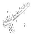
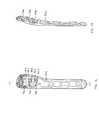
- FIG. 1is a perspective view of an embodiment of a proximal humeral fixation system according to the invention
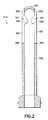
- FIG. 2is a schematic section view of a deployable post for the embodiment of FIG. 1 , shown in a non-deployed configuration;
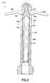
- FIG. 3is a schematic section view of a deployable post for the embodiment of FIG. 1 , shown in a deployed configuration;
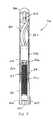
- FIG. 4is a schematic section view of a deployable post for the embodiment of FIG. 1 , shown in a released configuration;
- FIG. 5is a longitudinal section view of another embodiment of a deployable post, with the deployable anchors in a non-deployed configuration
- FIG. 6Ais a perspective view of a back end of the deployable post of FIG. 5 ;
- FIG. 6Bis a longitudinal section view of the back end of the deployable post of FIG. 5 ;
- FIG. 7is a perspective view of a central tube of the deployable post of FIG. 5 ;
- FIG. 8is a perspective view of a distal tip of the deployable post of FIG. 5 ;
- FIG. 9is a perspective view of a lead screw of the deployable post of FIG. 5 ;
- FIG. 10is a perspective view of a coupler of the deployable post of FIG. 5 ;
- FIG. 11is a perspective view of a bone anchor of the deployable post of FIG. 5 ;
- FIG. 12is a longitudinal section view of the deployable post of FIG. 5 , shown in a partially deployed configuration
- FIG. 13is a longitudinal section view of the deployable post of FIG. 5 , shown in a fully deployed configuration
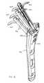
- FIG. 14is a perspective view of another system of the invention shown with deployable posts in the configuration of FIG. 13 ;
- FIG. 15is a perspective view of a cam for the system of FIG. 14 ;
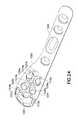
- FIG. 16is a plan view of the plate of the system of FIG. 14 ;
- FIG. 17is a longitudinal section view along line 17 - 17 in FIG. 16 ;
- FIG. 18is a perspective view of another system of the invention shown with the posts in a deployed configuration
- FIG. 19is a perspective view of a back end of the deployable posts used in the system shown in FIG. 18 ;
- FIG. 20is a longitudinal section view of the back end of the FIG. 19 ;
- FIG. 21is an enlarged broken section view of the back end and a set screw of the system shown in FIG. 18 ;
- FIG. 22is a broken partial section perspective view of the system shown in FIG. 18 ;
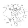
- FIG. 23is a lateral perspective view showing another embodiment of a proximal humeral fracture fixation system of the invention in place on the bone;
- FIG. 24is a perspective view of a plate of the system of FIG. 23 ;
- FIG. 25is a top view of the fixation system of FIG. 23 , shown implanted;
- FIG. 26is a medial view from within the bone of the fixation system of FIG. 23 ;
- FIG. 27is another view of the implanted fixation system of FIG. 23 ;
- FIG. 28is a view similar to FIG. 25 showing the system with deployed anchors
- FIG. 29is a view similar to FIG. 26 showing the system with deployed anchors
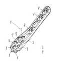
- FIG. 30is a perspective view showing another embodiment of a proximal humeral fracture fixation system of the invention.
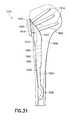
- FIG. 31is a schematic section view of a nail-plate embodiment of a proximal humeral fixation system according to the invention.
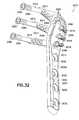
- FIG. 32is a perspective of an embodiment of a proximal humeral fracture fixation system according to the invention, shown with a humeral plate, posts, transverse cross pegs, and set screws;
- FIG. 33is another perspective view of the first embodiment of FIG. 32 , showing the humeral plate provided with one fixation post;
- FIG. 34is a perspective view showing the relationship between a fixation post, a transverse cross peg, and a set screw;
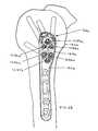
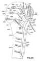
- FIG. 35illustrates the proximal humeral fracture fixation system of FIG. 32 implanted on the humerus to stabilize a fracture
- FIG. 36is a schematic view of an alternate embodiment of a cross peg for use in a fixation system according to the invention.
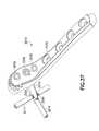
- FIG. 37is a perspective view of another embodiment of a proximal humeral fixation system according to the invention.
- FIG. 38is a perspective view of another embodiment of a proximal humeral fixation system according to the invention.
- FIG. 39is a perspective view of another nail-plate embodiment of a proximal humeral fixation system according to the invention.
- the system 510includes a humeral plate 512 with one or more post holes 536 in a head portion 534 thereof and screw holes 532 along a shaft portion 530 thereof.
- a tubular post 514is provided for each post hole 536 .
- the post 514includes a pair of arms 560 which are rotatably coupled about axes 561 adjacent the distal end 562 of the post 514 .
- Each arm 560includes a cam follower surface 564 generally adjacent its pivot axis 561 .
- the post 514includes windows 566 such that, when the arms 560 are in a closed position ( FIG. 2 ), the arms 560 may lie flush with the remainder of the post.
- the postalso includes an internal thread 568 .
- a set screw 570is provided which engages the internal thread 568 and includes a distal end provided with a cam 572 which operates to contact the cam follower surfaces 564 and move the arms 560 radially outward into the open configuration.
- the arms 560may each extend substantially 90° relative to the post 514 ; i.e., generally parallel to the articular surface and preferably in the anterior-posterior plane.
- the angle between each arm 560 and the post 514be acute, and preferably approximately 60° to 89°, so that the arms better approximate the contour of the articular surface of the humeral head.
- the boneis often spongy or brittle osteoporotic bone which permits movement of the arms therethrough.
- the arms 560 shownare relatively broad providing significant stability to the fracture and support to the articular bone surface once moved into the open configuration. However, in order to facilitate movement through the bone, the arms may be relatively thinner than shown.
- the set screwmay optionally include a bore 574 and distal openings 576 aligned with the windows 566 through which a preferably biodegradable bone cement or other preferably quick-setting filler material may be injected into the space created by the opening of the arms 560 (as shown by the arrows) to provide additional stability to the reduced fracture.
- the set screw 570is unthreaded and removed from the post 514 , and the post is then pulled from the bone. With the set screw 570 removed, the arms 560 are able to rotate upwards toward the upper end of the window 566 and stop against the distal end 562 of the post 514 as the post is withdrawn.
- the outer section of the post 714includes a proximal tubular back end 802 ( FIGS. 6A and 6B ), a central tube 804 ( FIG. 7 ) and a distal tip 806 ( FIG. 8 ).
- the back end 802includes a head 807 with reference structure, e.g., scalloped notches 808 , for rotationally orienting the post 802 relative to the humeral plate (as described in more detail below) and steps down to intermediate and smaller diameter portions 809 , 810 .
- the smaller diameter portion 810defines two diametrically opposed wells 812 .
- the distal end of the back end 802further includes an internal thread 817 .
- the tube 804seats over the smaller diameter portion 810 and includes two distally directed wings 814 which engage in the wells 812 and lock the tube 804 on the back end 802 in a flush engagement with the intermediate diameter portion 809 of the back end 802 .
- the tube 804includes a pair of windows 852 .
- the tip 806also described further below, extends into the distal end of the tube 804 and is fixed in position on the tube with a pin 818 extending through holes 819 , 821 in the tube 804 and tip 806 , respectively.
- a lead screw 820is provided in the back end 802 of the post 714 .
- the lead screw 820includes a proximal engagement socket 822 , e.g., square or hex socket, facilitating rotation of the lead screw 820 relative to the back end 802 by a tool, a threaded central portion 823 which engages the internal thread 817 of the back end 802 , and a distal stepped head portion 824 .
- the head portion 824is captured by, and rotatable relative to, a nest 826 of a coupler 828 .
- Coupler 828is defined by a two hermaphroditic elements 829 ( FIG.
- each hermaphroditic element 829also defines a track 837 and/or slot 838 into which a portion of an anchor 840 is movably coupled, as discussed below.
- the bone anchors 840include proximal axles 842 sized to travel within the slots 838 of the coupler 828 and have a back end 843 designed to ride along the track 837 of the coupler.
- the anchors 840are curved along an arc, and each has a relatively sharp bone piercing end 844 .
- the anchorsare preferably made of metal, but may be made of ceramic or a stiff bioabsorbable material.
- the tip 806defines two anchor guides 850 which each have a curvature corresponding to that of the convex side 845 of the anchors 840 .
- the tube 804defines two windows 852 , corresponding to the cross-sectional shape of the anchors 840 , through which the anchors 840 can be advanced out of the post 714 .
- the lead screw 820is rotationally advanced through the back end 802 to thereby cause advancement of the coupler 828 through the tube 804 .
- the anchors 840are pushed forward, contact the guides 850 and are deflected out of the windows 852 ( FIG. 7 ) in an outward direction, i.e., generally transverse to the axis of the post 714 .
- their axes of rotation within the tube 804changes, particularly relative to the initial orientation shown in FIG. 5 (as indicated by the broken circular marks on the coupler).
- the anchors 840when fully deployed, preferably project outwardly between 2 and 3.5 times the diameter of the tube 804 .
- the tube 804has a diameter of 4 mm, and the anchors 840 each project approximately 10 mm.
- a humeral plate 702is shown with a plurality of the posts 714 coupled thereto and with anchors 840 deployed.
- the posts 714can be locked to the plate 702 in any suitable manner. However, it is preferable that the posts 714 be locked relative to the plate 702 so that the orientation of the deployed anchors 840 be predetermined, e.g., generally parallel to each other as shown.
- each post 714be locked relative to the plate 702 without a threaded coupling therebetween, as it is difficult to machine a threaded coupling in which (i) the components are both fixedly and rigidly coupled together, and (ii) in which the rotational orientation of the post can be predetermined with certainty upon locking Notwithstanding the above, it is certainly possible and within the scope of the invention to machine a threaded coupling between the post and the plate with the entry and termination points arranged and with the required tolerances to obtain the same results; i.e., predetermined rotational orientation upon fully seating the post in the plate.
- the lock between a post 714 and its respective post hole 736preferably occurs within less than one complete rotation of the post 714 relative to the post hole 736 , and more preferably within 0° to 90° rotation.
- a preferred cam 856is generally cylindrical, but has an outer wall 858 that spirally increases in radius about approximately 270° of the circumference of the cam.
- the cam 856also includes a lower pin (not shown) about which the cam rotates, and an upper hex slot 860 for a driver.
- the plate 702includes a post hole 736 and an adjacent recessed cam slot 862 with a centering hole 863 which receives the centering pin.
- the cam 856is rotated so that its smallest radius is positioned toward the post hole.
- the post 714is received through the post hole 736 , oriented so that a scalloped notch 808 at the back end 802 of the post fits about the outside of the cam 856 , and pushed fully into the post hole.
- the cam 856is then rotated with a driver to provide contact between a larger radiused portion of the cam and the post to provide sufficient contact therebetween to effectively lock the post 714 to the plate 702 .
- FIGS. 18 through 20another embodiment of a system for rotationally and axially locking the posts relative to the plate is shown.
- the posts 914are substantially as described above with respect to post 714 .
- the back end 1002 of the post 914includes ears 1008 and a circular arrangement of resilient, radially outwardly directed catches 1009 .
- the back end 1002 of post 914includes a diametric bore 1011 to facilitate removal of an implanted post, if necessary, as described in more detail below.
- the systemincludes a set screw 1056 which locks the post 914 relative to the plate 902 , as also described below.
- the set screw 1056includes a recess 1058 in which the catches 1009 engage, but which also allows the set screw 1056 to be rotatable relative to the catches.
- each post hole 936 of the plate 902is stepped in diameter, includes threads 1060 within an upper larger diameter portion, and two diametric ear portions 1062 .
- the post 914is inserted through the post hole 936 so that the ears 1008 align with the ear portions 1062 . This ensures proper alignment of the anchors 940 when they are later extended ( FIG. 18 ).
- the set screw 1056is rotated in engagement with the threads 1060 and rotated until the post 914 is rigidly locked in place.
- the set screw 1056is rotated into disengagement. In doing so, the set screw may release from the post. Should this occur, a tool (not shown) may be inserted into the diametric bore 1011 and pulled to withdraw the post from the bone and hole 936 .
- the system 1200includes a plate 1202 having a head portion 1234 with six post holes, including central post holes 1236 a , 1236 b , 1236 c , 1236 d (collectively, 1236 ) designed to accept posts having a threaded head, and proximal and distal posts 1237 a , 1237 b (collectively, 1237 ) which are preferably substantially similar to post holes 936 ( FIG. 22 ) for receiving posts which may optionally have deployable anchors.
- post holes 1237preferably include a system which locks the angular orientation of the post.
- Such systemis also adapted to receive conventional threaded-head posts (with or without any deployable support means for supporting the subchondral bone of the articular surface), as shown in FIGS. 25 and 26 .
- posts without any support meansare used, the post holes do not require any system for angularly indexing or precisely fixing the posts. Referring still to FIGS.
- the central post holes 1236 a , 1236 b , 1236 c , 1236 ddefine axes illustrated by the posts 1214 a , 1214 b , 1214 c , 1214 d therethrough which are angularly oblique from each other, causing the posts to diverge both laterally and longitudinally.
- the proximal and distal post holes 1237 a , 1237 bdefine axes which are preferably laterally aligned and angularly convergent, as illustrated by posts 1215 a , 1215 b.
- the head portion 1234is also provided with five alignment holes 1218 a , 1218 b , 1218 c , 1218 d , 1218 e (collectively, 1218 ), each sized to closely receive a K-wire (substantially smaller than a respective post for the post holes) along a fixed axis.
- the axis of 1218 eis directed toward the center of the articular surface of the humeral head.
- the alignment holes 1218are angularly oriented within the head portion 1234 of the plate so as to present a path for K-wires which will outline various boundaries of the posts or identify a point of interest relative to the implanted posts. More particularly, as shown in FIGS.
- K-wires 1220 , 1222 positioned in holes 1218 b , 1218 cdefine the upper and lower bounds of posts 1214 a , 1214 b , 1214 c , 1214 d
- K-wire 1224 positioned in hole 1218 eis directed to the center of the articular surface and defines a central location towards which the axes of the proximal and distal post holes 1215 a , 1215 b converge.
- a narrow suture rail 1240extends about the proximal portion of the head portion 1234 .
- the suture rail 1240is elevated relative to the lower surface 1250 of the head portion to facilitate entry of a suture needle through the rail and recessed relative to the upper surface 1252 to present a relatively low unobtrusive profile.
- the fracturein use, by way of a delto-pectoral approach, the fracture is exposed and debrided. Traction and direct manipulation are used to reduce the fracture, and the anatomical relationship between the articular surface of the subchondral bone 1350 and the humeral shaft 1352 is restored in both its angular alignment and retroversion.
- the position for the plate 1202is then located on the humerus 1300 , preferably immediately posterior to the intertubercle groove and approximately 1.5-2.0 cm below the insertion of the supraspinatus.
- the plateis then provisionally secured to the distal fragment using, e.g.
- Axes of the alignment holescorrespond to axes of adjacent post holes.
- the K-wires 1220 , 1222 , 1224are viewed fluoroscopically to provide an indication as to whether the posts will be properly oriented. If the placement is correct, the K-wires maintain the position of the plate over the fracture. The posts holes may then be drilled with confidence that their locations and orientations are proper. If placement is not optimal, the K-wires are removed and the surgeon can relocate the plate and/or can reorient the K-wires and drills again. Since each K-wire is of relatively small diameter, the bone is not significantly damaged by the drilling process and the surgeon is not committed to the initial drill location and/or orientation.
- the shaft 1230 of the plate 1212is then fixed to the humeral diaphysis 1352 by fully inserting the cortical screw through the oblong hole 1232 a . Any K-wires that may have been used to secure the shaft are removed.
- a drill guide(not shown) holes for the posts are drilled.
- a depth gauge(not shown) the depth of the drilled holes is determined.
- Appropriate length posts 1214 a , 1214 b , 1214 c , 1214 d , 1215 a , 1215 bare inserted using a driver.
- the distal end of the postsare preferably 4-6 mm below the articular surface of the subchondral bone 1350 . Radiographic confirmation of the correct fracture reduction and post placement is then made.
- the surgeondeploys the anchors 1340 to provide support for the articular surface of the subchondral bone 1350 .
- axes A C1 , and A C2 through the deployed anchorsare substantially parallel to each other and transverse to a longitudinal axis A S through the shaft portion 1230 of the plate 1202 .
- the K-wires 1220 , 1222 , 1224 in the head portion 1234are preferably removed prior to anchor deployment.
- FIG. 30another embodiment of a shoulder plate 1402 is shown.
- the plate 1402is substantially similar to plate 1202 in features, but includes several significant structural distinctions.
- the proximal end of the head portion 1434includes three discrete generally radially-arranged suture guides 1440 with lateral openings.
- the guides 1440are spaced to permit needle access therethrough without obstruction from the adjacent guide(s).
- additional K-wire openings 1418 f , 1418 gare provided anterior and posterior the central K-wire opening 1418 e to permit the use of additional K-wires for fluoroscopic visualization of the arrangement of the posts within the bone prior to insertion of the posts.
- the additional openings 1418 f , 1418 gmay be particularly useful where the surgical approach creates difficulty in the use of one of more of the other openings.
- the bone screw holes 1460are designed for use with specific cortical screws and set screws (not shown) which permits independent application of compression and locking of the cortical screw.
- Such screw holes, cortical screws and set screws, as well as other suitable screw systems which may be used in the fracture fixation systems described herein,are described in U.S. Ser. No. 11/040,779, filed simultaneously herewith, which is hereby incorporated by reference herein in its entirety.
- each of the platesincludes a substantially straight edge.
- the straight edgeis edge 1470
- oppositeis a slightly curved edge 1472 .
- the other shoulder plates described hereininclude corresponding straight and curved edges and when placed according to the above teaching provide the desired placement.
- the potential for interference between the head portion of the plate and the acromion when the arm is raisedis minimized.
- FIG. 31another embodiment of a humeral fracture fixation system 1510 is shown coupled to a shoulder 1500 , with the posts 1514 extending across a fracture 1502 .
- the system 1510includes a device 1512 having a plate-like head portion 1534 , a neck 1515 , and a shaft 1530 .
- the neck 1515 of the deviceis attached to the head portion 1534 so as to seat intrafocally just below the fracture 1502 .
- one or more of the post holes 1537 in the plate-like head portion 1534extends through the neck 1515 .
- the post holes 1537are preferably axially angularly offset relative to each other.
- the shaft portion 1530 of the device 1512defines an intramedullary nail sized to be inserted intrafocally (through the fracture) and then be received within the medullary canal of the proximal humerus.
- the device 1512is a “nail-plate.”
- the shaft portion 1530preferably extends from a lower central location of the head portion 1534 , in distinction from the inferior end thereof.
- the shaft portion 1530preferably tapers to facilitate entry into the medullary canal and terminates in a smooth bend 1532 which facilitates intrafocal entry of the end of the shaft, and further insertion into the medullary canal 1504 .
- the shaft portion 1530is preferably offset relative to the head portion 1534 , as the shaft portion 1530 is intended to reside within the bone and the head portion 1534 is intended to reside on the surface of the bone.
- Holes 1560 , 1562are provided in the shaft portion for receiving fasteners.
- the holes 1560 , 1562are preferably threaded, and thus adapted to receive machine screws which can pull the shaft portion 1530 against the cortex of the bone.
- non-threaded holesmay be used, and standard cortical screws provided to couple the shaft to the humeral cortex.
- “Nail-plates”are described in more detail in co-owned U.S. Ser. No. 10/315,787, filed Dec. 10, 2002, which is hereby incorporated by reference herein in its entirety.
- FIGS. 32 through 35another embodiment of a proximal humeral fixation system 2010 for fixation of a humeral fracture 2011 ( FIG. 35 ) of the left arm is shown.
- the system 2010includes a humeral plate 2012 , and a plurality of rigid posts 2014 , rigid cross pegs 2016 , set screws 2018 , and cortical screws 2019 , all for coupling the plate 2012 to the humerus 2020 ( FIG. 35 ) and stabilizing the fracture.
- the system 2010may also include K-wires 2022 and suture material 2024 , as discussed below.
- the humeral plate 2012has a shaft portion 2030 and a head portion 2034 .
- the head portion 2034is angled slightly relatively to the shaft portion to properly seat on the humeral anatomy.
- the shaft portion 2030includes screw holes 2032 , one of which may be slotted or oblong (as indicated by dotted line 2032 a in FIG. 32 ) to permit the plate 2012 to be longitudinally moved relative to a screw placed therethrough.
- the shaft portionmay also include one or more K-wire holes 2033 .
- the head portion 2034is provided with post holes 2036 . As indicated by the posts 2014 in FIG. 32 , axes through the post holes 2036 are preferably substantially in a common plane but preferably diverge from each other within the common plane.
- the planeis in 10° retroversion relative to a frontal and vertical plane.
- the post holes 2036define a locking structure 2038 , discussed in more detail below.
- tangential to each post holes 2036 on diametrically opposite sides thereofare slots 2040 for receiving an alignment jig (not shown) to aid in drilling respective holes for cross pegs 2016 .
- each post 2014includes a head portion 2046 with slots 2048 which lock in a particular rotational orientation relative to the locking structure 2038 of the post hole 2036 , similar to a bayonet lock.
- the post 2014also includes a plurality of transverse, preferably parallel holes 2050 longitudinally displaced along the shaft 2052 of the post 2014 .
- the post 2014further includes an axial bore 2054 which extends from the head portion 2046 at least to the furthest transverse hole 2050 , and an internal thread (not shown) below a driver recess 2056 and preferably below the slots 2048 .
- the cross pegs 2016each include a head 2060 for receiving a driver, and a shaft portion 2062 .
- the shaft portion 2062is optionally threaded at 2064 adjacent the head 2060 for engagement with cancellous bone, but such is not required.
- the cross pegs 2016can be extended through a transverse hole 2050 in a post 2014 in the anterior-posterior plane and locked in place with a set screw 2018 .
- the set screw 2018includes a head 2066 with a driver recess 2068 and external threads 2070 , and a shaft 2072 .
- a set screw 2018 of appropriate lengthis inserted through the axial bore 2054 of the post 2014 until the end 2076 of the set screw 2018 contacts the portion of the shaft 2062 of the cross peg 2016 extending through a transverse hole 2050 of the post 2014 .
- the set screw 2018is threadably locked relative to the post 2014 to exert pressure on the cross peg 2016 and thereby retain the cross peg 2016 .
- Set screws 2018 of various lengthsmay be provided for locking cross pegs in any of the longitudinally displaced transverse holes.
- common length set screwsmay be cut down in size, if necessary, to the appropriate length prior to insertion through the bore 2054 of a post 2014 .
- the set screws 2018may be scored along the shaft 2072 to facilitate breaking or cutting the set screws to appropriate length.
- the cross pegsmay include transverse holes through which the set screws can be passed. In that manner common length set screws can be used, provided the cross pegs are rotationally aligned to receive the set screws through the transverse holes.
- the head portion 2034 of the plate 2012includes a lower proximal recess 2080 and a plurality of suture holes 2082 thereabout.
- the recess 2080raises the proximal portion of the head portion 2034 of the plate 2012 off the surface of the bone (as shown in FIG. 35 ) to allow the surgeon to pass a needle (not shown) with suture material 2024 through the suture holes 2082 and between the plate 2012 and the bone 2020 .
- suture material 2024can be used to secure tendons 2084 of the rotator cuff to the plate 2012 to place retaining force on smaller fragments of the fracture.
- the suture material 2024is preferably metal braid or cable.
- the head portion 2034includes a plurality of alignment holes 2086 , 2088 , and 2090 which are sized to closely receive individual K-wires in a particular orientation.
- proximal alignment hole 2086is located to define an axis which corresponds to the anterior-superior boundary of the posts 2014
- distal alignment hole 2088is located to define an axis which corresponds to the anterior-inferior boundary of the posts 2014
- relatively central alignment hole 2090is located to define an axis which corresponds to the posterior boundary of the posts 2014 .
- the fractureis reduced and the humeral plate 2012 is placed on the proximal humerus in an appropriate location (as discussed above), with the head portion 34 generally opposite the articular surface 2042 .
- the head portion 2034is then tacked onto the humeral head 2044 with K-wires 2022 drilled through the alignment holes 2086 , 2088 , 2090 , and the shaft portion 2030 is preferably tacked to the distal fragment with one or more K-wires 2022 , through K-wires holes 2033 in the shaft portion, or with one or more screws 2019 in the screw holes 2032 .
- the fracture and location of the K-wires 2022is examined, e.g., under fluoroscopy, to determine whether the fracture is reduced in an anatomically correct manner and if the K-wires 2022 are properly aligned relative to the anatomy.
- the fluoroscopically viewed K-wires 2022provide an indication as to whether the posts 2014 will be properly oriented in relation to the fracture and the articular surface of the subchondral bone. If placement is not optimal, the K-wires 2022 can be removed and the surgeon has an opportunity to relocate and/or reorient the K-wires 2022 and drill again. Since each K-wire 2022 is of relatively small diameter relative to the posts 2014 , the bone is not significantly damaged by the drilling process and the surgeon is not committed to the initial drill location and/or orientation.
- shaft portion 2030 fixationmay be delayed until after placement of the head portion 2034 of the plate 2012 is determined to be desirable (via visualization of the K-wires), and then preferably at least one cortical screw 2019 is inserted through a screw hole 2032 to stabilize the shaft portion 2030 to the humerus 2020 .
- Holesare then drilled through the post holes 2036 of the head portion 34 of the plate 2012 for the posts 2014 .
- the holesare drilled across fracture 2011 .
- the drill bit for drilling holes through the posts 2014corresponds in diameter to the post holes 2036 such that no alignment jig is necessarily required, although one may be used is desired.
- the holesare drilled through the relatively soft spongy bone of the humeral head 2044 until the surgeon can ‘feel’ the harder cortex of the subchondral bone of the articular surface 2042 . All posts holes may be drilled before proceeding.
- one post holemay be drilled, and for that post hole, a post can be inserted therein and coupled to the plate, an associated cross peg hole can be drilled, and a cross peg can be coupled to the post, as described in more detail below, prior to proceeding to drill the other post holes.
- the posts 2014are then inserted through the post holes 2036 , and rotated to lock the heads 2046 of the posts 2014 relative to the locking structure 2038 of the head portion 2034 of the plate 2012 .
- the locking coupling of 2046 and 2038constrains the transverse holes 2050 to be in a predetermined rotational orientation relative to the plate 2012 .
- a jig(not shown) is then coupled to the internal threads of a post 2014 and rotationally aligned relative to the tangential slots 2040 of the post hole 2036 to align a guide for drilling a hole in alignment with one of the transverse holes 2050 of that post 2014 .
- the jigmay be coupled directly the plate 2012 .
- a cross peg 2016is then inserted through the drilled hole and extended through the transverse hole 2050 of that post 2014 such that the cross peg 2016 extends parallel to the articular surface 2042 of the humeral head 2044 on the opposite side of the fracture 2011 from the plate 2012 .
- the particular transverse hole 2050 in which a particular cross peg 2016 is insertedcan be determined by the surgeon based upon the size of the humeral head 2044 and the location of the fracture. More particularly, it is desirable for each cross peg 2016 to extend just below the articular surface 2042 . If the cross peg 2016 is within the articular surface 2042 it will cause interference with the joint. If the cross peg 2016 is too far away from the articular surface 2042 , there will be too much spongy bone between the hard articular surface 2042 and the cross peg 2016 which could cause the fractured humeral head 2044 to collapse.
- the cross pegs 2016are subject to little resistance through the drilled holes and the surgeon has tactile sensation as to when the cross pegs 2016 have been extended through the appropriate transverse holes 2050 and when the ends of the cross pegs 2016 have reached hard cortical bone. It is undesirable to force the cross pegs through the cortical bone such that the ends of the cross pegs 2016 are exposed.
- the set screw 2018is inserted through the axial bore 2054 of the post 2014 and threadably coupled to the post 2014 such that the end of the set screw 2018 seats against the cross peg 2016 locking the cross peg in place. The process is repeated for the other posts 2014 and cross pegs 2016 .
- the K-wires 2022are removed.
- the sutures 2024are added, and the remaining cortical screws 2019 , if not already inserted, are inserted to further stabilize the fracture.
- the posts 2014are oriented perpendicular to the articular surface 2042 but do not extend far enough to break through the articular surface.
- the plate 2012 and cross pegs 2016sandwich the fracture 2011 to provide a stabilizing framework.
- the cross pegs 2016 extending through the transverse holes 2050 in the posts 2014are oriented parallel to the articular surface 2042 and provide a structure which locks the plate relative to the bone. Furthermore, such placement and orientation of the cross pegs 2016 will not result in any damage to, irritation to, or interference with the articular surface of the shoulder joint.
- the cross peg 2116includes threads 2190 along a central portion of its shaft which are preferably self-tapping and spaced appropriately to engage the wall 2051 surrounding the holes 2050 of the post 2014 .
- this threaded engagementmay limit the surgeon's tactile sensation of when the far cortex is reached by the cross peg.
- the cross peg 2116may be provided with a shoulder 2192 that limits its introduction, i.e. such that the shoulder 2192 can not extend through the transverse hole 2050 .
- the cross peg 2116may include cutting flutes 2194 which permit drill-less introduction.
- transverse holesmay be provide with machine threads, and the cross pegs may be likewise threaded with machine threads such that the cross peg and post can threadably engage together without the cross peg tapping into the post.
- any of the above described cross pegsmay be headless.
- the cross pegis adapted to be seated beneath the surface of the bone.
- such a crossis suited to extend through the articular surface without interference with the shoulder joint if extension of a cross peg through the articular surface is necessary or desirable for stabilization of a particular fracture with the system of the invention.
- a single post 2214may be inserted through any of the post holes 2236 in plate 2212 , although only a single post hole is required in this embodiment.
- the post 2214includes holes 2250 , 2252 which are oriented transverse to each other, preferably at 90°, and preferably perpendicular to the longitudinal axis of the post 2214 .
- Cross pegs 2216 , 2217are then inserted through holes 2250 , 2252 and preferably locked relative to the post.
- Cross peg 2216extends parallel to the anterior-posterior plane of the articular surface, and cross peg 2217 extends parallel to the relatively transverse plane.
- Cross pegs 2216 , 2217are also shown in a headless design, described above, which can be seated beneath the surface of the bone and provide no interference with the articular surface.
- FIG. 38another embodiment of humeral fracture fixation system 2310 according to the invention is shown.
- system 2310two laterally offset posts 2314 , 2315 are displaced in an anterior-posterior plane.
- the postsare preferably angled relative to each other in the same plane by, e.g., 20° to 90°.
- the posts 2314 , 2315may be vertically offset in the proximal-distal plane.
- Each of the posts 2314 , 2315has at least one transverse hole 2350 , with an axis therethrough preferably oriented substantially transverse to the anterior-posterior plane when the system 2310 , with plate 2312 , is implanted at the shoulder, and may have a plurality of such holes 2350 longitudinally displaced along the post.
- a cross peg 2316 , 2317is inserted through a selected one of the holes 2350 in each post 2314 , 2315 .
- System 2410may include any of the post and cross peg configurations discussed above (e.g., posts 2436 and pegs 2416 ), any other transverse scaffold construction that captures the fracture between the plate-like head portion 2434 of the device 2412 and one or more cross pegs, or any post with a deployable supports/anchors.
- posts and cortical screwshave been disclosed in relation to particular embodiments, it will be understood that only one post is required, and fewer or more cortical screw holes can be provided and/or screws can be used.
- cortical screwsare disclosed for coupling the shaft portion to the bone, other fasteners can likewise be used.
- postsand ‘pegs’ have been used to described particular elements of the invention, it is understood that such terms are used as a matter of convenience, and are not intended to confer particular structure when used in the claims. Thus, what is referred to as a ‘post’ is intended to broadly read on any rigid shaft-like fastener coupled to the plate.
- pegis intended to broadly read on any shaft-like element which extends in transverse relation one of the posts and is (i) coupled to such post and/or (ii) extends through a transverse hole formed within the post.
- the pegmay be a screw, a non-threaded rod, a K-wire, etc.
- left-hand humeral platesare shown, it is recognized that right-hand humeral plates are generally mirror-images of the illustrated left-hand plates.
- the systemhas been described for use with respect to fractures, it is appreciated that it may also be used in the treatment of osteotomies and non-unions of the proximal humerus and other bones having an articular surface with a convex shape. It will therefore be appreciated by those skilled in the art that yet other modifications could be made to the provided invention without deviating from its scope as claimed.
Landscapes
- Health & Medical Sciences (AREA)
- Orthopedic Medicine & Surgery (AREA)
- Surgery (AREA)
- Life Sciences & Earth Sciences (AREA)
- Heart & Thoracic Surgery (AREA)
- Nuclear Medicine, Radiotherapy & Molecular Imaging (AREA)
- Engineering & Computer Science (AREA)
- Biomedical Technology (AREA)
- Neurology (AREA)
- Medical Informatics (AREA)
- Molecular Biology (AREA)
- Animal Behavior & Ethology (AREA)
- General Health & Medical Sciences (AREA)
- Public Health (AREA)
- Veterinary Medicine (AREA)
- Surgical Instruments (AREA)
Abstract
Description
Claims (16)
Priority Applications (2)
| Application Number | Priority Date | Filing Date | Title |
|---|---|---|---|
| US11/040,724US7780710B2 (en) | 2004-01-23 | 2005-01-21 | System for stabilization of fractures of convex articular bone surfaces including subchondral support structure |
| US11/341,120US7938850B2 (en) | 2002-05-30 | 2006-01-26 | Nail plate |
Applications Claiming Priority (5)
| Application Number | Priority Date | Filing Date | Title |
|---|---|---|---|
| US53858904P | 2004-01-23 | 2004-01-23 | |
| US54612704P | 2004-02-20 | 2004-02-20 | |
| US59811004P | 2004-08-02 | 2004-08-02 | |
| US64343205P | 2005-01-07 | 2005-01-07 | |
| US11/040,724US7780710B2 (en) | 2004-01-23 | 2005-01-21 | System for stabilization of fractures of convex articular bone surfaces including subchondral support structure |
Related Child Applications (1)
| Application Number | Title | Priority Date | Filing Date |
|---|---|---|---|
| US11/341,120Continuation-In-PartUS7938850B2 (en) | 2002-05-30 | 2006-01-26 | Nail plate |
Publications (2)
| Publication Number | Publication Date |
|---|---|
| US20050182405A1 US20050182405A1 (en) | 2005-08-18 |
| US7780710B2true US7780710B2 (en) | 2010-08-24 |
Family
ID=34841884
Family Applications (1)
| Application Number | Title | Priority Date | Filing Date |
|---|---|---|---|
| US11/040,724Active2026-09-14US7780710B2 (en) | 2002-05-30 | 2005-01-21 | System for stabilization of fractures of convex articular bone surfaces including subchondral support structure |
Country Status (1)
| Country | Link |
|---|---|
| US (1) | US7780710B2 (en) |
Cited By (32)
| Publication number | Priority date | Publication date | Assignee | Title |
|---|---|---|---|---|
| US20090216270A1 (en)* | 2008-02-27 | 2009-08-27 | Scott Humphrey | Fixable suture anchor plate and method for tendon-to-bone repair |
| US20100023012A1 (en)* | 2008-07-23 | 2010-01-28 | University Of Louisville Research Foundation, Inc. | Device and method to prevent hip fractures |
| US20100185285A1 (en)* | 2009-01-19 | 2010-07-22 | Richard Perkins | Annular repair device and method |
| US20100211074A1 (en)* | 2007-07-24 | 2010-08-19 | Henrik Hansson | Device for Fixation of Bone Fragments at Bone Fractures |
| US20100274245A1 (en)* | 2003-11-21 | 2010-10-28 | Eduardo Gonzalez-Hernandez | Fracture fixation system |
| US20110224736A1 (en)* | 2010-03-09 | 2011-09-15 | Humphrey C Scott | Proximal humerus fracture repair plate and system |
| US20130006247A1 (en)* | 2011-06-29 | 2013-01-03 | Nextremity Solutions, Llc | Bone plate hybrid device |
| US20130030478A1 (en)* | 2011-07-26 | 2013-01-31 | Rodriguez Jose A | Anchor wire system and method |
| US8469999B2 (en) | 2008-04-17 | 2013-06-25 | Eduardo Gonzalez-Hernandez | Soft tissue attachment system and clip |
| US8535322B1 (en)* | 2012-11-07 | 2013-09-17 | Roy Y. Powlan | Hip nail and inertial insertion tooling |
| US8764808B2 (en) | 2008-03-10 | 2014-07-01 | Eduardo Gonzalez-Hernandez | Bone fixation system |
| US8821546B2 (en)* | 2007-11-06 | 2014-09-02 | Stanus Investments, Inc. | Vertebral screw arrangement with locking pin |
| US8870963B2 (en) | 2010-10-27 | 2014-10-28 | Toby Orthopaedics, Inc. | System and method for fracture replacement of comminuted bone fractures or portions thereof adjacent bone joints |
| US8961573B2 (en) | 2010-10-05 | 2015-02-24 | Toby Orthopaedics, Inc. | System and method for facilitating repair and reattachment of comminuted bone portions |
| US9254154B2 (en) | 2011-03-03 | 2016-02-09 | Toby Orthopaedic, Inc. | Anterior lesser tuberosity fixed angle fixation device and method of use associated therewith |
| US9271772B2 (en) | 2011-10-27 | 2016-03-01 | Toby Orthopaedics, Inc. | System and method for fracture replacement of comminuted bone fractures or portions thereof adjacent bone joints |
| US9283008B2 (en) | 2012-12-17 | 2016-03-15 | Toby Orthopaedics, Inc. | Bone plate for plate osteosynthesis and method for use thereof |
| US9333014B2 (en) | 2013-03-15 | 2016-05-10 | Eduardo Gonzalez-Hernandez | Bone fixation and reduction apparatus and method for fixation and reduction of a distal bone fracture and malunion |
| US9402667B2 (en) | 2011-11-09 | 2016-08-02 | Eduardo Gonzalez-Hernandez | Apparatus and method for use of the apparatus for fracture fixation of the distal humerus |
| US20160270830A1 (en)* | 2015-03-22 | 2016-09-22 | Rahul Vaidya | Method and Apparatus for Minimally Invasive Subcutaneous Treatment of Humerus Fractures |
| US9468479B2 (en) | 2013-09-06 | 2016-10-18 | Cardinal Health 247, Inc. | Bone plate |
| US9510880B2 (en) | 2013-08-13 | 2016-12-06 | Zimmer, Inc. | Polyaxial locking mechanism |
| US9707020B2 (en) | 2011-08-15 | 2017-07-18 | Zimmer Gmbh | Femoral fracture fixation device |
| US9730797B2 (en) | 2011-10-27 | 2017-08-15 | Toby Orthopaedics, Inc. | Bone joint replacement and repair assembly and method of repairing and replacing a bone joint |
| US20180250040A1 (en)* | 2015-03-25 | 2018-09-06 | Pier Giovanni Menci | Intramedullary nail for the treatment of fractures of the long bones |
| US20180256218A1 (en)* | 2017-03-13 | 2018-09-13 | Extremity Medical, Llc | Calcaneal cross medullary plate |
| US10213237B2 (en) | 2014-10-03 | 2019-02-26 | Stryker European Holdings I, Llc | Periprosthetic extension plate |
| US10251685B2 (en) | 2016-03-17 | 2019-04-09 | Stryker European Holdings I, Llc | Floating locking insert |
| US10792081B2 (en) | 2014-08-28 | 2020-10-06 | Nextremity Solutions, Inc. | Bone fixation devices and methods |
| US11172969B2 (en)* | 2020-01-28 | 2021-11-16 | Loubert S. Suddaby | Fusion device |
| US11583326B2 (en)* | 2020-01-28 | 2023-02-21 | Loubert S. Suddaby | Fusion device |
| US12226133B2 (en) | 2017-04-06 | 2025-02-18 | Extremity Medical Llc | Orthopedic plate with modular peg and compression screw |
Families Citing this family (40)
| Publication number | Priority date | Publication date | Assignee | Title |
|---|---|---|---|---|
| US7326212B2 (en) | 2002-11-19 | 2008-02-05 | Acumed Llc | Bone plates with reference marks |
| US7717945B2 (en) | 2002-07-22 | 2010-05-18 | Acumed Llc | Orthopedic systems |
| US20050240187A1 (en) | 2004-04-22 | 2005-10-27 | Huebner Randall J | Expanded fixation of bones |
| US7537604B2 (en)* | 2002-11-19 | 2009-05-26 | Acumed Llc | Bone plates with slots |
| CN1309352C (en)* | 2002-07-22 | 2007-04-11 | 精密医疗责任有限公司 | Bone fusion system |
| AU2003294414B2 (en)* | 2002-11-19 | 2009-03-12 | Acumed Llc | Deformable bone plates |
| AU2003294342A1 (en) | 2002-11-19 | 2004-06-15 | Acumed Llc | Guide system for bone-repair devices |
| WO2004112587A2 (en) | 2003-06-20 | 2004-12-29 | Acumed Llc | Bone plates with intraoperatively tapped apertures |
| US7635365B2 (en) | 2003-08-28 | 2009-12-22 | Ellis Thomas J | Bone plates |
| US20050085818A1 (en)* | 2003-10-17 | 2005-04-21 | Huebner Randall J. | Systems for distal radius fixation |
| WO2005102193A2 (en) | 2004-04-19 | 2005-11-03 | Acumed, Llc | Placement of fasteners into bone |
| US8394130B2 (en) | 2005-03-17 | 2013-03-12 | Biomet C.V. | Modular fracture fixation system |
| US7604657B2 (en)* | 2005-09-19 | 2009-10-20 | Depuy Products, Inc. | Bone fixation plate with complex suture anchor locations |
| US8177818B2 (en) | 2005-09-08 | 2012-05-15 | Securos, Inc. | Fixation plate |
| US7699880B2 (en) | 2005-10-24 | 2010-04-20 | Depuy Products, Inc. | Bone fixation system and bone screws having anti-back out feature |
| US8926675B2 (en) | 2006-04-11 | 2015-01-06 | Biomet Manufacturing, Llc | Contoured bone plate |
| US20070270849A1 (en) | 2006-04-21 | 2007-11-22 | Orbay Jorge L | Fixation Plate With Multifunctional Holes |
| US20080086137A1 (en)* | 2006-10-04 | 2008-04-10 | Robert Probe | Fixation of femoral neck fractures |
| KR101503665B1 (en)* | 2007-06-22 | 2015-03-18 | 이픽스 오소페딕스, 인코포레이티드 | Intramedullary rod for pivoting a fastener |
| US20130244193A1 (en)* | 2008-07-10 | 2013-09-19 | Nei-Chang Yu | System and Method for Orthodontic System |
| US12285197B2 (en) | 2008-10-10 | 2025-04-29 | Acumed Llc | Bone fixation system with opposed mounting portions |
| US9237910B2 (en) | 2012-01-26 | 2016-01-19 | Acute Innovations Llc | Clip for rib stabilization |
| US8790343B2 (en) | 2008-10-11 | 2014-07-29 | Epix Orthopaedics, Inc. | Intramedullary rod with pivotable and fixed fasteners and method for using same |
| US8926611B2 (en)* | 2009-09-14 | 2015-01-06 | Zimmer Gmbh | Angular lag implant for intramedullary nails |
| US8568417B2 (en) | 2009-12-18 | 2013-10-29 | Charles River Engineering Solutions And Technologies, Llc | Articulating tool and methods of using |
| FR2956971B1 (en) | 2010-03-08 | 2012-03-02 | Memometal Technologies | PLATE OSTEOSYNTHESIS SYSTEM |
| FR2956972B1 (en) | 2010-03-08 | 2012-12-28 | Memometal Technologies | ARTICULATED OSTEOSYNTHESIS PLATE |
| WO2011163092A2 (en)* | 2010-06-25 | 2011-12-29 | Amit Gupta | Plate system for managing a bone fracture |
| JP5629505B2 (en) | 2010-06-25 | 2014-11-19 | 山洋電気株式会社 | Centrifugal fan |
| US8579945B2 (en)* | 2010-08-13 | 2013-11-12 | DePuy Synthes Products, LLC | Bone stabilization device |
| DE102011116732A1 (en)* | 2011-09-02 | 2013-03-07 | Königsee Implantate GmbH | Device for fixing a bone fractured in the region of the femoral neck |
| WO2013049849A2 (en) | 2011-09-30 | 2013-04-04 | Acute Innovations, Llc, An Oregon Limited Liability Company | Bone fixation system with opposed mounting portions |
| JP6247644B2 (en) | 2012-02-08 | 2017-12-13 | エピックス オーソペディックス インコーポレイテッド | Implant insertion device having a continuously adjustable targeting assembly |
| US9486201B2 (en) | 2012-09-27 | 2016-11-08 | Depuy Mitek, Llc | Directionally specific bone anchors and method |
| ES2781751T3 (en)* | 2012-10-12 | 2020-09-07 | Swemac Innovation Ab | Fixation media for fixation of bone fragments in bone fractures |
| EP2730244B1 (en)* | 2012-11-07 | 2017-04-26 | Arthrex, Inc. | Bone plate with suture holes for soft tissue reattachment on the diaphyseal region of the plate |
| US10123828B2 (en) | 2013-03-15 | 2018-11-13 | Epix Orthopaedics, Inc. | Implantable device with pivotable fastener and self-adjusting set screw |
| EP3164093B1 (en) | 2014-07-03 | 2024-02-14 | Acumed LLC | Bone plate with movable joint |
| DE102021112429B4 (en) | 2021-05-12 | 2025-02-27 | Roman Stauch | Intramedullary nail for transverse distraction |
| CN117653303B (en)* | 2023-12-15 | 2025-02-07 | 中国人民解放军总医院第四医学中心 | A triangular internal fixation and strengthening device for femoral neck fracture |
Citations (126)
| Publication number | Priority date | Publication date | Assignee | Title |
|---|---|---|---|---|
| US1091674A (en) | 1913-09-02 | 1914-03-31 | Gramberry Sutton | Screw. |
| US2077804A (en) | 1936-05-19 | 1937-04-20 | Morrison Gordon Monroe | Device for treating fractures of the neck of the femur |
| US2500370A (en) | 1947-06-30 | 1950-03-14 | Mckibbin Genevieve | Repair of femur fracture |
| US2685877A (en) | 1952-03-20 | 1954-08-10 | Dobelle Martin | Femoral head prosthesis |
| US3002514A (en)* | 1958-01-24 | 1961-10-03 | Deyerle William Minor | Hip setting pin |
| US3489143A (en) | 1967-12-15 | 1970-01-13 | William X Halloran | Convertible hip pin |
| US3552389A (en) | 1966-06-22 | 1971-01-05 | Synthes Ag | Osteosynthetic pressure plate construction |
| US3716050A (en) | 1971-02-11 | 1973-02-13 | F Johnston | Olecranon plate |
| US3779240A (en) | 1972-03-31 | 1973-12-18 | S Kondo | Compression plate for osteosynthesis |
| US3791380A (en)* | 1971-12-13 | 1974-02-12 | G Dawidowski | Method and apparatus of immobilizing a fractured femur |
| FR2233973A1 (en) | 1973-06-25 | 1975-01-17 | Chatin Robert | Osteosynthesis plate for femoral fracture surgery - has anchoring holes in ablong flat portion and widened blade |
| USRE28841E (en) | 1966-06-22 | 1976-06-08 | Synthes A.G. | Osteosynthetic pressure plate construction |
| FR2405062A1 (en) | 1977-10-10 | 1979-05-04 | Dayan Robert | Surgical repair plate for lower fractures of femur - has concave cross section and enlarged end with staggered countersunk screw holes |
| FR2405705A1 (en) | 1977-10-14 | 1979-05-11 | Dayan Robert | Surgical repair plate for tibia upper end fracture - has elongated length with enlarged head and countersunk for fixing screws |
| FR2405706A1 (en) | 1977-10-14 | 1979-05-11 | Dayan Robert | Surgical repair plate for humerus lower end fracture - has end with unequal curved branches and countersunk holes for fixing screws |
| CH611147A5 (en) | 1977-01-07 | 1979-05-31 | Mueller Kurt | Osteosynthesis compression plate |
| US4219015A (en) | 1977-04-22 | 1980-08-26 | Institut Straumann Ag | Plates for osteosynthesis |
| US4408601A (en) | 1980-04-14 | 1983-10-11 | Wilh, Wenk Ag | Bone compression plate |
| USRE31628E (en) | 1966-06-22 | 1984-07-10 | Synthes Ag | Osteosynthetic pressure plate construction |
| US4493317A (en) | 1980-11-20 | 1985-01-15 | Synthes Ltd. (U.S.A.) | Surgical compression plate and drill guide |
| US4498468A (en) | 1981-05-11 | 1985-02-12 | Hansson Lars Ingvar | Bone fixation driving instrument |
| US4513744A (en) | 1981-03-16 | 1985-04-30 | Synthes Ag | Surgical compression plate |
| US4561432A (en) | 1983-09-15 | 1985-12-31 | Floyd A. Coard, M.D. | Fractured femur fixation system |
| US4565193A (en) | 1982-09-13 | 1986-01-21 | Elke Streli | Pronged plate for resetting fractured bones |
| US4622959A (en) | 1985-03-05 | 1986-11-18 | Marcus Randall E | Multi-use femoral intramedullary nail |
| SU1279626A1 (en) | 1985-06-06 | 1986-12-30 | Центральный научно-исследовательский институт травматологии и ортопедии им.Н.Н.Приорова | Compression device for osteosynthesis |
| US4632101A (en) | 1985-01-31 | 1986-12-30 | Yosef Freedland | Orthopedic fastener |
| EP0207884A2 (en) | 1985-07-05 | 1987-01-07 | Mecron Medizinische Produkte Gmbh | Straight self-tensioning bone plate |
| US4721103A (en) | 1985-01-31 | 1988-01-26 | Yosef Freedland | Orthopedic device |
| US4733654A (en) | 1986-05-29 | 1988-03-29 | Marino James F | Intramedullar nailing assembly |
| US4794919A (en) | 1986-01-31 | 1989-01-03 | Nilsson John S | Fixating device |
| FR2606268B1 (en) | 1986-11-07 | 1989-02-03 | Landos Applic Orthopediques Fs | DEVICE FOR FEMALE NECK OSTEOSYNTHESIS |
| US4838252A (en) | 1985-08-30 | 1989-06-13 | Synthes | Osteosynthetic compression plate |
| US4858602A (en) | 1985-12-06 | 1989-08-22 | Howmedica GmbH Werk Schonkirchen | Bone nail for the treatment of upper arm fractures |
| DE8907443U1 (en) | 1989-06-19 | 1989-09-14 | Aesculap AG, 7200 Tuttlingen | Intramedullary splint for a long bone |
| US4927421A (en) | 1989-05-15 | 1990-05-22 | Marlowe Goble E | Process of endosteal fixation of a ligament |
| US4957497A (en) | 1984-10-27 | 1990-09-18 | Thomas Hoogland | Device for osteosynthesis |
| US4957118A (en) | 1988-01-15 | 1990-09-18 | Jay Erlebacher | Electrode lead |
| US4988350A (en) | 1988-06-24 | 1991-01-29 | Wolfgang Herzberg | Device for reconnecting a broken bone |
| US5002544A (en) | 1987-12-02 | 1991-03-26 | Synthes (U.S.A.) | Osteosynthetic pressure plate osteosynthetic compression plate |
| US5006120A (en) | 1989-10-10 | 1991-04-09 | Carter Peter R | Distal radial fracture set and method for repairing distal radial fractures |
| US5041114A (en) | 1986-06-23 | 1991-08-20 | Pfizer Hospital Products Group, Inc. | Modular femoral fixation system |
| US5085660A (en) | 1990-11-19 | 1992-02-04 | Lin Kwan C | Innovative locking plate system |
| US5127914A (en) | 1989-02-10 | 1992-07-07 | Calderale Pasquale M | Osteosynthesis means for the connection of bone fracture segments |
| US5129901A (en) | 1991-06-10 | 1992-07-14 | Decoste Vern X | Cannulated orthopedic screw |
| US5151103A (en) | 1987-11-03 | 1992-09-29 | Synthes (U.S.A.) | Point contact bone compression plate |
| US5160335A (en) | 1988-12-15 | 1992-11-03 | Jaquet Orthopedie S.A. | Pin holder support |
| US5180383A (en) | 1991-10-09 | 1993-01-19 | Haydon Frank A | Method and device for attaching artificial joint implants to the ends of bones |
| US5190544A (en) | 1986-06-23 | 1993-03-02 | Pfizer Hospital Products Group, Inc. | Modular femoral fixation system |
| US5197966A (en) | 1992-05-22 | 1993-03-30 | Sommerkamp T Greg | Radiodorsal buttress blade plate implant for repairing distal radius fractures |
| US5269784A (en) | 1991-12-10 | 1993-12-14 | Synthes (U.S.A.) | Screw nut for plate osteosynthesis |
| US5275601A (en) | 1991-09-03 | 1994-01-04 | Synthes (U.S.A) | Self-locking resorbable screws and plates for internal fixation of bone fractures and tendon-to-bone attachment |
| US5304180A (en) | 1992-01-17 | 1994-04-19 | Slocum D Barclay | Tibial osteotomy fixation plate |
| US5324291A (en) | 1992-12-21 | 1994-06-28 | Smith & Nephew Richards, Inc. | Bone section reattachment apparatus and method |
| US5324290A (en) | 1992-09-24 | 1994-06-28 | Danek Medical, Inc. | Anterior thoracolumbar plate |
| US5364399A (en) | 1993-02-05 | 1994-11-15 | Danek Medical, Inc. | Anterior cervical plating system |
| DE4343117A1 (en) | 1993-12-17 | 1995-06-22 | Wolter Dietmar | Bone fixation system for Osteosynthesis |
| US5458654A (en) | 1993-07-14 | 1995-10-17 | Ao-Forschungsinstitut Davos | Screw-fixed femoral component for hip joint prosthesis |
| US5472444A (en) | 1994-05-13 | 1995-12-05 | Acumed, Inc. | Humeral nail for fixation of proximal humeral fractures |
| US5489284A (en) | 1994-07-15 | 1996-02-06 | Smith & Nephew Richards Inc. | Cannulated modular intramedullary nail |
| DE4438264A1 (en) | 1994-09-08 | 1996-03-14 | Schaefer Micomed Gmbh | Assembly to link spine vertebrae |
| US5514138A (en) | 1991-02-08 | 1996-05-07 | Pfizer Inc. | Connector having a stop member |
| US5531748A (en) | 1992-11-24 | 1996-07-02 | Fixano | Osteosynthesis device for trochanteric or trochanteric-diaphyseal fracture |
| US5578035A (en) | 1995-05-16 | 1996-11-26 | Lin; Chih-I | Expandable bone marrow cavity fixation device |
| US5601553A (en) | 1994-10-03 | 1997-02-11 | Synthes (U.S.A.) | Locking plate and bone screw |
| US5674222A (en) | 1994-06-01 | 1997-10-07 | Synthes (U.S.A.) | Forked plate |
| US5676667A (en) | 1995-12-08 | 1997-10-14 | Hausman; Michael | Bone fixation apparatus and method |
| US5702399A (en) | 1996-05-16 | 1997-12-30 | Pioneer Laboratories, Inc. | Surgical cable screw connector |
| US5709686A (en) | 1995-03-27 | 1998-01-20 | Synthes (U.S.A.) | Bone plate |
| US5749872A (en) | 1995-09-08 | 1998-05-12 | Ace Medical Company | Keyed/keyless barrel for bone plates |
| US5759184A (en) | 1993-07-23 | 1998-06-02 | Santangelo; Massimo | Device for preventive support of the femur |
| US5776194A (en) | 1996-04-25 | 1998-07-07 | Nuvana Medical Innovations, Llc | Intermedullary rod apparatus and methods of repairing proximal humerus fractures |
| US5796139A (en)* | 1995-02-23 | 1998-08-18 | Sanyo Electric Co., Ltd. | Semiconductor device |
| US5797913A (en) | 1995-07-28 | 1998-08-25 | Groupe Lepine | Device for securing bone parts after osteotomy, or for reducing a bone fracture and securing the fractured bone parts, once these parts have been brought together |
| US5810823A (en) | 1994-09-12 | 1998-09-22 | Synthes (U.S.A.) | Osteosynthetic bone plate and lock washer |
| US5810820A (en)* | 1994-05-20 | 1998-09-22 | Santori; Francesco Saverio | Endomedullar device for nailing long distance |
| US5840078A (en) | 1995-03-01 | 1998-11-24 | Yerys; Paul | Method and apparatus for mechanical attachment of soft tissue to bone tissue |
| US5843127A (en) | 1994-08-22 | 1998-12-01 | Le Medical Technologies, Inc. | Fixation device and method for installing same |
| US5849004A (en) | 1996-07-17 | 1998-12-15 | Bramlet; Dale G. | Surgical anchor |
| US5882351A (en) | 1995-09-29 | 1999-03-16 | Biomedical Enterprises, Inc. | Fasteners having coordinated self-seeking conforming members and uses thereof |
| US5931839A (en) | 1995-01-27 | 1999-08-03 | Medoff; Robert J. | Pin plate for fixation of bone fractures |
| US5938664A (en) | 1998-03-31 | 1999-08-17 | Zimmer, Inc. | Orthopaedic bone plate |
| DE9321544U1 (en) | 1993-12-09 | 1999-09-23 | Königsee Implantate und Instrumente zur Ostheosynthese GmbH, 07426 Königsee | Osteosynthetic plate |
| US5976139A (en)* | 1996-07-17 | 1999-11-02 | Bramlet; Dale G. | Surgical fastener assembly |
| US5993449A (en) | 1995-11-30 | 1999-11-30 | Synthes (Usa) | Bone-fixing device |
| DE19857279A1 (en) | 1998-12-11 | 2000-06-15 | Onur Tarhan | Bone screw |
| US6096040A (en) | 1996-06-14 | 2000-08-01 | Depuy Ace Medical Company | Upper extremity bone plates |
| DE29907161U1 (en) | 1999-04-22 | 2000-08-24 | Wischhöfer, Edlef, Prof. Dr. Dr.med., 85092 Kösching | Blocking plate for osteosynthesis on the humerus |
| US6183475B1 (en) | 1998-12-18 | 2001-02-06 | Sulzer Orthopedics Inc. | Distal femoral osteotomy system and method |
| US6206881B1 (en) | 1995-09-06 | 2001-03-27 | Synthes (Usa) | Bone plate |
| USD443060S1 (en) | 2000-06-01 | 2001-05-29 | Bristol-Myers Squibb Company | Bone plate |
| US6270499B1 (en) | 1997-10-20 | 2001-08-07 | Synthes (U.S.A.) | Bone fixation device |
| US6322562B1 (en) | 1998-12-19 | 2001-11-27 | Dietmar Wolter | Fixation system for bones |
| US20020032446A1 (en)* | 2000-02-01 | 2002-03-14 | Orbay Jorge L. | Fixation plate system for dorsal wrist fracture fixation |
| US6358250B1 (en) | 2000-02-01 | 2002-03-19 | Hand Innovations, Inc. | Volar fixation system |
| DE20200705U1 (en) | 2002-01-18 | 2002-03-28 | Aesculap AG & Co. KG, 78532 Tuttlingen | Intramedullary osteosynthesis implant |
| US6379359B1 (en) | 2000-05-05 | 2002-04-30 | University Of North Carolina At Chapel Hill | Percutaneous intrafocal plate system |
| US6406477B1 (en) | 2000-07-27 | 2002-06-18 | Koi Inc. | Intramedullary nail |
| US6409768B1 (en) | 2000-03-16 | 2002-06-25 | Slobodan Tepic | Screw anchored joint prosthesis |
| US6440135B2 (en) | 2000-02-01 | 2002-08-27 | Hand Innovations, Inc. | Volar fixation system with articulating stabilization pegs |
| US6443954B1 (en) | 2001-04-24 | 2002-09-03 | Dale G. Bramlet | Femoral nail intramedullary system |
| US6454770B1 (en) | 1997-09-04 | 2002-09-24 | Synthes (Usa) | Symmetrical bone plate |
| US6468278B1 (en) | 1997-11-14 | 2002-10-22 | Medos Medizintechnik Gmbh | Implant for the stabilization of a fracture |
| US20020156474A1 (en)* | 2001-04-20 | 2002-10-24 | Michael Wack | Polyaxial locking plate |
| US20020161369A1 (en) | 2001-04-25 | 2002-10-31 | Bramlet Dale G. | Intramedullary nail |
| WO2002096309A1 (en) | 2001-05-28 | 2002-12-05 | Synthes Ag Chur | Bone plate for the fixation of fractures of the proximal humerus |
| US20030004514A1 (en) | 1999-12-03 | 2003-01-02 | Robert Frigg | Intramedullary nail |
| US6527776B1 (en) | 1997-02-11 | 2003-03-04 | Gary K. Michelson | Locking element for locking at least two bone screws to an orthopedic device |
| US6558388B1 (en) | 1999-08-30 | 2003-05-06 | Sulzer Orthopedics Ltd. | Intramedullary nail for the humerus |
| US6562042B2 (en) | 2000-02-02 | 2003-05-13 | Owen A. Nelson | Orthopedic implant used to repair intertrochanteric fractures and a method for inserting the same |
| US6579294B2 (en) | 2000-07-26 | 2003-06-17 | Stryker Trauma Gmbh | Locking nail for fracture fixation |
| USD479331S1 (en) | 2002-11-05 | 2003-09-02 | Zimmer | Orthopedic bone plate |
| US6623486B1 (en) | 1999-09-13 | 2003-09-23 | Synthes (U.S.A.) | bone plating system |
| US6648889B2 (en) | 2001-04-24 | 2003-11-18 | Dale G. Bramlet | Intramedullary hip nail with bifurcated lock |
| US6648890B2 (en) | 1996-11-12 | 2003-11-18 | Triage Medical, Inc. | Bone fixation system with radially extendable anchor |
| US6669701B2 (en) | 2000-01-27 | 2003-12-30 | Synthes (Usa) | Bone plate |
| US20040002735A1 (en)* | 2002-06-27 | 2004-01-01 | Lizardi Jose E. | Suture anchor |
| US6685706B2 (en) | 2001-11-19 | 2004-02-03 | Triage Medical, Inc. | Proximal anchors for bone fixation system |
| US6689135B2 (en) | 2002-01-25 | 2004-02-10 | Albert Enayati | Expandable bone fastener and installation tool |
| US6706046B2 (en) | 2000-02-01 | 2004-03-16 | Hand Innovations, Inc. | Intramedullary fixation device for metaphyseal long bone fractures and methods of using the same |
| US20040193162A1 (en)* | 2003-02-03 | 2004-09-30 | Bramlet Dale G. | Femoral neck compression screw system with ortho-biologic material delivery capability |
| EP1468655A2 (en) | 2003-03-26 | 2004-10-20 | Precimed S.A. | Locking bone plate |
| US20050010226A1 (en) | 2003-05-30 | 2005-01-13 | Grady Mark P. | Bone plate |
| US6866665B2 (en) | 2003-03-27 | 2005-03-15 | Hand Innovations, Llc | Bone fracture fixation system with subchondral and articular surface support |
| WO2005037117A1 (en) | 2003-10-18 | 2005-04-28 | Intercus Gmbh | System for the minimally invasive treatment of a bone fracture, especially of a proximal humeral or femoral fracture |
| US6926720B2 (en) | 2003-10-15 | 2005-08-09 | Hand Innovations, Llc | Jig assembly for implantation of a fracture fixation device |
- 2005
- 2005-01-21USUS11/040,724patent/US7780710B2/enactiveActive
Patent Citations (131)
| Publication number | Priority date | Publication date | Assignee | Title |
|---|---|---|---|---|
| US1091674A (en) | 1913-09-02 | 1914-03-31 | Gramberry Sutton | Screw. |
| US2077804A (en) | 1936-05-19 | 1937-04-20 | Morrison Gordon Monroe | Device for treating fractures of the neck of the femur |
| US2500370A (en) | 1947-06-30 | 1950-03-14 | Mckibbin Genevieve | Repair of femur fracture |
| US2685877A (en) | 1952-03-20 | 1954-08-10 | Dobelle Martin | Femoral head prosthesis |
| US3002514A (en)* | 1958-01-24 | 1961-10-03 | Deyerle William Minor | Hip setting pin |
| USRE28841E (en) | 1966-06-22 | 1976-06-08 | Synthes A.G. | Osteosynthetic pressure plate construction |
| US3552389A (en) | 1966-06-22 | 1971-01-05 | Synthes Ag | Osteosynthetic pressure plate construction |
| US3668972A (en) | 1966-06-22 | 1972-06-13 | Martin Allgower | Osteosynthetic pressure plate construction |
| USRE31628E (en) | 1966-06-22 | 1984-07-10 | Synthes Ag | Osteosynthetic pressure plate construction |
| US3489143A (en) | 1967-12-15 | 1970-01-13 | William X Halloran | Convertible hip pin |
| US3716050A (en) | 1971-02-11 | 1973-02-13 | F Johnston | Olecranon plate |
| US3791380A (en)* | 1971-12-13 | 1974-02-12 | G Dawidowski | Method and apparatus of immobilizing a fractured femur |
| US3779240A (en) | 1972-03-31 | 1973-12-18 | S Kondo | Compression plate for osteosynthesis |
| FR2233973A1 (en) | 1973-06-25 | 1975-01-17 | Chatin Robert | Osteosynthesis plate for femoral fracture surgery - has anchoring holes in ablong flat portion and widened blade |
| CH611147A5 (en) | 1977-01-07 | 1979-05-31 | Mueller Kurt | Osteosynthesis compression plate |
| US4219015A (en) | 1977-04-22 | 1980-08-26 | Institut Straumann Ag | Plates for osteosynthesis |
| FR2405062A1 (en) | 1977-10-10 | 1979-05-04 | Dayan Robert | Surgical repair plate for lower fractures of femur - has concave cross section and enlarged end with staggered countersunk screw holes |
| FR2405706A1 (en) | 1977-10-14 | 1979-05-11 | Dayan Robert | Surgical repair plate for humerus lower end fracture - has end with unequal curved branches and countersunk holes for fixing screws |
| FR2405705A1 (en) | 1977-10-14 | 1979-05-11 | Dayan Robert | Surgical repair plate for tibia upper end fracture - has elongated length with enlarged head and countersunk for fixing screws |
| US4408601A (en) | 1980-04-14 | 1983-10-11 | Wilh, Wenk Ag | Bone compression plate |
| US4493317A (en) | 1980-11-20 | 1985-01-15 | Synthes Ltd. (U.S.A.) | Surgical compression plate and drill guide |
| US4513744A (en) | 1981-03-16 | 1985-04-30 | Synthes Ag | Surgical compression plate |
| US4498468A (en) | 1981-05-11 | 1985-02-12 | Hansson Lars Ingvar | Bone fixation driving instrument |
| US4565193A (en) | 1982-09-13 | 1986-01-21 | Elke Streli | Pronged plate for resetting fractured bones |
| US4561432A (en) | 1983-09-15 | 1985-12-31 | Floyd A. Coard, M.D. | Fractured femur fixation system |
| US4957497A (en) | 1984-10-27 | 1990-09-18 | Thomas Hoogland | Device for osteosynthesis |
| US4721103A (en) | 1985-01-31 | 1988-01-26 | Yosef Freedland | Orthopedic device |
| US4632101A (en) | 1985-01-31 | 1986-12-30 | Yosef Freedland | Orthopedic fastener |
| US4622959A (en) | 1985-03-05 | 1986-11-18 | Marcus Randall E | Multi-use femoral intramedullary nail |
| SU1279626A1 (en) | 1985-06-06 | 1986-12-30 | Центральный научно-исследовательский институт травматологии и ортопедии им.Н.Н.Приорова | Compression device for osteosynthesis |
| EP0207884A2 (en) | 1985-07-05 | 1987-01-07 | Mecron Medizinische Produkte Gmbh | Straight self-tensioning bone plate |
| US4838252A (en) | 1985-08-30 | 1989-06-13 | Synthes | Osteosynthetic compression plate |
| US4858602A (en) | 1985-12-06 | 1989-08-22 | Howmedica GmbH Werk Schonkirchen | Bone nail for the treatment of upper arm fractures |
| US4794919A (en) | 1986-01-31 | 1989-01-03 | Nilsson John S | Fixating device |
| US4733654A (en) | 1986-05-29 | 1988-03-29 | Marino James F | Intramedullar nailing assembly |
| US5041114A (en) | 1986-06-23 | 1991-08-20 | Pfizer Hospital Products Group, Inc. | Modular femoral fixation system |
| US5364398A (en) | 1986-06-23 | 1994-11-15 | Pfizer Hospital Products Group, Inc. | Modular femoral fixation system |
| US5190544A (en) | 1986-06-23 | 1993-03-02 | Pfizer Hospital Products Group, Inc. | Modular femoral fixation system |
| FR2606268B1 (en) | 1986-11-07 | 1989-02-03 | Landos Applic Orthopediques Fs | DEVICE FOR FEMALE NECK OSTEOSYNTHESIS |
| US5151103A (en) | 1987-11-03 | 1992-09-29 | Synthes (U.S.A.) | Point contact bone compression plate |
| US5002544A (en) | 1987-12-02 | 1991-03-26 | Synthes (U.S.A.) | Osteosynthetic pressure plate osteosynthetic compression plate |
| US4957118A (en) | 1988-01-15 | 1990-09-18 | Jay Erlebacher | Electrode lead |
| US4988350A (en) | 1988-06-24 | 1991-01-29 | Wolfgang Herzberg | Device for reconnecting a broken bone |
| US5160335A (en) | 1988-12-15 | 1992-11-03 | Jaquet Orthopedie S.A. | Pin holder support |
| US5127914A (en) | 1989-02-10 | 1992-07-07 | Calderale Pasquale M | Osteosynthesis means for the connection of bone fracture segments |
| US4927421A (en) | 1989-05-15 | 1990-05-22 | Marlowe Goble E | Process of endosteal fixation of a ligament |
| DE8907443U1 (en) | 1989-06-19 | 1989-09-14 | Aesculap AG, 7200 Tuttlingen | Intramedullary splint for a long bone |
| US5006120A (en) | 1989-10-10 | 1991-04-09 | Carter Peter R | Distal radial fracture set and method for repairing distal radial fractures |
| US5085660A (en) | 1990-11-19 | 1992-02-04 | Lin Kwan C | Innovative locking plate system |
| US5514138A (en) | 1991-02-08 | 1996-05-07 | Pfizer Inc. | Connector having a stop member |
| US5129901A (en) | 1991-06-10 | 1992-07-14 | Decoste Vern X | Cannulated orthopedic screw |
| US5275601A (en) | 1991-09-03 | 1994-01-04 | Synthes (U.S.A) | Self-locking resorbable screws and plates for internal fixation of bone fractures and tendon-to-bone attachment |
| US5180383A (en) | 1991-10-09 | 1993-01-19 | Haydon Frank A | Method and device for attaching artificial joint implants to the ends of bones |
| US5269784A (en) | 1991-12-10 | 1993-12-14 | Synthes (U.S.A.) | Screw nut for plate osteosynthesis |
| US5304180A (en) | 1992-01-17 | 1994-04-19 | Slocum D Barclay | Tibial osteotomy fixation plate |
| US5197966A (en) | 1992-05-22 | 1993-03-30 | Sommerkamp T Greg | Radiodorsal buttress blade plate implant for repairing distal radius fractures |
| US5324290A (en) | 1992-09-24 | 1994-06-28 | Danek Medical, Inc. | Anterior thoracolumbar plate |
| US5531748A (en) | 1992-11-24 | 1996-07-02 | Fixano | Osteosynthesis device for trochanteric or trochanteric-diaphyseal fracture |
| US5324291A (en) | 1992-12-21 | 1994-06-28 | Smith & Nephew Richards, Inc. | Bone section reattachment apparatus and method |
| US5364399A (en) | 1993-02-05 | 1994-11-15 | Danek Medical, Inc. | Anterior cervical plating system |
| US5458654A (en) | 1993-07-14 | 1995-10-17 | Ao-Forschungsinstitut Davos | Screw-fixed femoral component for hip joint prosthesis |
| US5759184A (en) | 1993-07-23 | 1998-06-02 | Santangelo; Massimo | Device for preventive support of the femur |
| DE9321544U1 (en) | 1993-12-09 | 1999-09-23 | Königsee Implantate und Instrumente zur Ostheosynthese GmbH, 07426 Königsee | Osteosynthetic plate |
| DE4343117A1 (en) | 1993-12-17 | 1995-06-22 | Wolter Dietmar | Bone fixation system for Osteosynthesis |
| US5472444A (en) | 1994-05-13 | 1995-12-05 | Acumed, Inc. | Humeral nail for fixation of proximal humeral fractures |
| US5810820A (en)* | 1994-05-20 | 1998-09-22 | Santori; Francesco Saverio | Endomedullar device for nailing long distance |
| US5674222A (en) | 1994-06-01 | 1997-10-07 | Synthes (U.S.A.) | Forked plate |
| US5489284A (en) | 1994-07-15 | 1996-02-06 | Smith & Nephew Richards Inc. | Cannulated modular intramedullary nail |
| US5843127A (en) | 1994-08-22 | 1998-12-01 | Le Medical Technologies, Inc. | Fixation device and method for installing same |
| DE4438264A1 (en) | 1994-09-08 | 1996-03-14 | Schaefer Micomed Gmbh | Assembly to link spine vertebrae |
| US5810823A (en) | 1994-09-12 | 1998-09-22 | Synthes (U.S.A.) | Osteosynthetic bone plate and lock washer |
| US5601553A (en) | 1994-10-03 | 1997-02-11 | Synthes (U.S.A.) | Locking plate and bone screw |
| US5931839A (en) | 1995-01-27 | 1999-08-03 | Medoff; Robert J. | Pin plate for fixation of bone fractures |
| US5796139A (en)* | 1995-02-23 | 1998-08-18 | Sanyo Electric Co., Ltd. | Semiconductor device |
| US5840078A (en) | 1995-03-01 | 1998-11-24 | Yerys; Paul | Method and apparatus for mechanical attachment of soft tissue to bone tissue |
| US5709686A (en) | 1995-03-27 | 1998-01-20 | Synthes (U.S.A.) | Bone plate |
| US5578035A (en) | 1995-05-16 | 1996-11-26 | Lin; Chih-I | Expandable bone marrow cavity fixation device |
| US5797913A (en) | 1995-07-28 | 1998-08-25 | Groupe Lepine | Device for securing bone parts after osteotomy, or for reducing a bone fracture and securing the fractured bone parts, once these parts have been brought together |
| US6206881B1 (en) | 1995-09-06 | 2001-03-27 | Synthes (Usa) | Bone plate |
| US5749872A (en) | 1995-09-08 | 1998-05-12 | Ace Medical Company | Keyed/keyless barrel for bone plates |
| US6287310B1 (en) | 1995-09-29 | 2001-09-11 | Biomedical Enterprises, Inc. | Fasteners having coordinated self-seeking conforming members and uses thereof |
| US5882351A (en) | 1995-09-29 | 1999-03-16 | Biomedical Enterprises, Inc. | Fasteners having coordinated self-seeking conforming members and uses thereof |
| US5993449A (en) | 1995-11-30 | 1999-11-30 | Synthes (Usa) | Bone-fixing device |
| US5676667A (en) | 1995-12-08 | 1997-10-14 | Hausman; Michael | Bone fixation apparatus and method |
| US6183474B1 (en) | 1996-03-13 | 2001-02-06 | Dale G. Bramlet | Surgical fastener assembly |
| US5776194A (en) | 1996-04-25 | 1998-07-07 | Nuvana Medical Innovations, Llc | Intermedullary rod apparatus and methods of repairing proximal humerus fractures |
| US5702399A (en) | 1996-05-16 | 1997-12-30 | Pioneer Laboratories, Inc. | Surgical cable screw connector |
| US6096040A (en) | 1996-06-14 | 2000-08-01 | Depuy Ace Medical Company | Upper extremity bone plates |
| US5976139A (en)* | 1996-07-17 | 1999-11-02 | Bramlet; Dale G. | Surgical fastener assembly |
| US5849004A (en) | 1996-07-17 | 1998-12-15 | Bramlet; Dale G. | Surgical anchor |
| US6648890B2 (en) | 1996-11-12 | 2003-11-18 | Triage Medical, Inc. | Bone fixation system with radially extendable anchor |
| US6527776B1 (en) | 1997-02-11 | 2003-03-04 | Gary K. Michelson | Locking element for locking at least two bone screws to an orthopedic device |
| US6454770B1 (en) | 1997-09-04 | 2002-09-24 | Synthes (Usa) | Symmetrical bone plate |
| US6270499B1 (en) | 1997-10-20 | 2001-08-07 | Synthes (U.S.A.) | Bone fixation device |
| US6468278B1 (en) | 1997-11-14 | 2002-10-22 | Medos Medizintechnik Gmbh | Implant for the stabilization of a fracture |
| US5938664A (en) | 1998-03-31 | 1999-08-17 | Zimmer, Inc. | Orthopaedic bone plate |
| DE19857279A1 (en) | 1998-12-11 | 2000-06-15 | Onur Tarhan | Bone screw |
| US6183475B1 (en) | 1998-12-18 | 2001-02-06 | Sulzer Orthopedics Inc. | Distal femoral osteotomy system and method |
| US6322562B1 (en) | 1998-12-19 | 2001-11-27 | Dietmar Wolter | Fixation system for bones |
| DE29907161U1 (en) | 1999-04-22 | 2000-08-24 | Wischhöfer, Edlef, Prof. Dr. Dr.med., 85092 Kösching | Blocking plate for osteosynthesis on the humerus |
| US6558388B1 (en) | 1999-08-30 | 2003-05-06 | Sulzer Orthopedics Ltd. | Intramedullary nail for the humerus |
| US6623486B1 (en) | 1999-09-13 | 2003-09-23 | Synthes (U.S.A.) | bone plating system |
| US20030004514A1 (en) | 1999-12-03 | 2003-01-02 | Robert Frigg | Intramedullary nail |
| US6669701B2 (en) | 2000-01-27 | 2003-12-30 | Synthes (Usa) | Bone plate |
| US6364882B1 (en) | 2000-02-01 | 2002-04-02 | Hand Innovations, Inc. | Volar fixation system |
| US6706046B2 (en) | 2000-02-01 | 2004-03-16 | Hand Innovations, Inc. | Intramedullary fixation device for metaphyseal long bone fractures and methods of using the same |
| US6440135B2 (en) | 2000-02-01 | 2002-08-27 | Hand Innovations, Inc. | Volar fixation system with articulating stabilization pegs |
| US6358250B1 (en) | 2000-02-01 | 2002-03-19 | Hand Innovations, Inc. | Volar fixation system |
| US20020032446A1 (en)* | 2000-02-01 | 2002-03-14 | Orbay Jorge L. | Fixation plate system for dorsal wrist fracture fixation |
| US6562042B2 (en) | 2000-02-02 | 2003-05-13 | Owen A. Nelson | Orthopedic implant used to repair intertrochanteric fractures and a method for inserting the same |
| US6409768B1 (en) | 2000-03-16 | 2002-06-25 | Slobodan Tepic | Screw anchored joint prosthesis |
| US6379359B1 (en) | 2000-05-05 | 2002-04-30 | University Of North Carolina At Chapel Hill | Percutaneous intrafocal plate system |
| USD443060S1 (en) | 2000-06-01 | 2001-05-29 | Bristol-Myers Squibb Company | Bone plate |
| US6579294B2 (en) | 2000-07-26 | 2003-06-17 | Stryker Trauma Gmbh | Locking nail for fracture fixation |
| US6406477B1 (en) | 2000-07-27 | 2002-06-18 | Koi Inc. | Intramedullary nail |
| US20020156474A1 (en)* | 2001-04-20 | 2002-10-24 | Michael Wack | Polyaxial locking plate |
| US6443954B1 (en) | 2001-04-24 | 2002-09-03 | Dale G. Bramlet | Femoral nail intramedullary system |
| US6648889B2 (en) | 2001-04-24 | 2003-11-18 | Dale G. Bramlet | Intramedullary hip nail with bifurcated lock |
| US20020161369A1 (en) | 2001-04-25 | 2002-10-31 | Bramlet Dale G. | Intramedullary nail |
| WO2002096309A1 (en) | 2001-05-28 | 2002-12-05 | Synthes Ag Chur | Bone plate for the fixation of fractures of the proximal humerus |
| US6685706B2 (en) | 2001-11-19 | 2004-02-03 | Triage Medical, Inc. | Proximal anchors for bone fixation system |
| DE20200705U1 (en) | 2002-01-18 | 2002-03-28 | Aesculap AG & Co. KG, 78532 Tuttlingen | Intramedullary osteosynthesis implant |
| US6689135B2 (en) | 2002-01-25 | 2004-02-10 | Albert Enayati | Expandable bone fastener and installation tool |
| US20040002735A1 (en)* | 2002-06-27 | 2004-01-01 | Lizardi Jose E. | Suture anchor |
| USD479331S1 (en) | 2002-11-05 | 2003-09-02 | Zimmer | Orthopedic bone plate |
| US20040193162A1 (en)* | 2003-02-03 | 2004-09-30 | Bramlet Dale G. | Femoral neck compression screw system with ortho-biologic material delivery capability |
| EP1468655A2 (en) | 2003-03-26 | 2004-10-20 | Precimed S.A. | Locking bone plate |
| US6866665B2 (en) | 2003-03-27 | 2005-03-15 | Hand Innovations, Llc | Bone fracture fixation system with subchondral and articular surface support |
| US20050010226A1 (en) | 2003-05-30 | 2005-01-13 | Grady Mark P. | Bone plate |
| US6926720B2 (en) | 2003-10-15 | 2005-08-09 | Hand Innovations, Llc | Jig assembly for implantation of a fracture fixation device |
| WO2005037117A1 (en) | 2003-10-18 | 2005-04-28 | Intercus Gmbh | System for the minimally invasive treatment of a bone fracture, especially of a proximal humeral or femoral fracture |
Non-Patent Citations (7)
| Title |
|---|
| Hessman et al., "Internal Fixation of Proximal Humeral Fractures: Current Concepts," European Journal of Trauma, 2003 No. 5, p. 253-261. |
| Locking Compression Plate (LCP) System (brochure). SYNTHES. West Chester, PA: 2003. (6 pages). |
| Orbay, Jorge L. MD, "Advances in Distal Radius Fixation", Orthopedic Technology Review-Surgical Innovations, vol. 5, No. 2, Mar./Apr. 2003.* |
| Osgood and Ahmad, "Two- and Three-Part Fractures of the Proximal Humerus," Shoulder and Elbow Trauma, 2004, Chapter 13, p. 169-182. |
| Philos, The Anatomical Fixation System for the Proximal Humerus with Angular Stability, XP-002205191, Jan. 1, 2001, pp. 1-3. |
| The Mayo Clinic Congruent Elbow Plates (catalog). ACUMED. Hillsboro, OR: 2003. (20 pages). |
| Zimmer Periarticular Plating System- Low-Profile Fixation (catalog). Zimmer, Inc., 2003. (8 pages). |
Cited By (66)
| Publication number | Priority date | Publication date | Assignee | Title |
|---|---|---|---|---|
| US20100274245A1 (en)* | 2003-11-21 | 2010-10-28 | Eduardo Gonzalez-Hernandez | Fracture fixation system |
| US8574234B2 (en) | 2003-11-21 | 2013-11-05 | Toby Orthopaedics, Inc. | Fracture fixation system |
| US8361075B2 (en) | 2003-11-21 | 2013-01-29 | Toby Orthopaedics, Inc. | Method for repairing fractured bone |
| US8182485B1 (en) | 2003-11-21 | 2012-05-22 | Toby Orthopaedics, Llc | Fracture fixation system |
| US9358052B2 (en) | 2007-07-24 | 2016-06-07 | Henrik Hansson | Method for fixation of bone fragments at bone fractures |
| US9522025B2 (en)* | 2007-07-24 | 2016-12-20 | Henrik Hansson | Device for fixation of bone fragments at bone fractures |
| US20100211074A1 (en)* | 2007-07-24 | 2010-08-19 | Henrik Hansson | Device for Fixation of Bone Fragments at Bone Fractures |
| US8821546B2 (en)* | 2007-11-06 | 2014-09-02 | Stanus Investments, Inc. | Vertebral screw arrangement with locking pin |
| US8267973B2 (en)* | 2008-02-27 | 2012-09-18 | Shoulder Options, Inc. | Fixable suture anchor plate and method for tendon-to-bone repair |
| US20090216270A1 (en)* | 2008-02-27 | 2009-08-27 | Scott Humphrey | Fixable suture anchor plate and method for tendon-to-bone repair |
| US8764808B2 (en) | 2008-03-10 | 2014-07-01 | Eduardo Gonzalez-Hernandez | Bone fixation system |
| US8690916B2 (en) | 2008-04-17 | 2014-04-08 | Eduardo Gonzalez-Hernandez | Soft tissue attachment system and clip |
| US8469999B2 (en) | 2008-04-17 | 2013-06-25 | Eduardo Gonzalez-Hernandez | Soft tissue attachment system and clip |
| US9452003B2 (en)* | 2008-07-23 | 2016-09-27 | University Of Louisville Research Foundation, Inc. | Device and method to prevent hip fractures |
| US20100023012A1 (en)* | 2008-07-23 | 2010-01-28 | University Of Louisville Research Foundation, Inc. | Device and method to prevent hip fractures |
| US8182533B2 (en)* | 2009-01-19 | 2012-05-22 | Richard Perkins | Annular repair device and method |
| US20100185285A1 (en)* | 2009-01-19 | 2010-07-22 | Richard Perkins | Annular repair device and method |
| US20110224736A1 (en)* | 2010-03-09 | 2011-09-15 | Humphrey C Scott | Proximal humerus fracture repair plate and system |
| US8961573B2 (en) | 2010-10-05 | 2015-02-24 | Toby Orthopaedics, Inc. | System and method for facilitating repair and reattachment of comminuted bone portions |
| US9271776B2 (en) | 2010-10-05 | 2016-03-01 | Toby Orthopaedics, Inc. | System and method for facilitating repair and reattachment of comminuted bone portions |
| US9757240B2 (en) | 2010-10-27 | 2017-09-12 | Toby Orthopaedics, Inc. | System and method for fracture replacement of comminuted bone fractures or portions thereof adjacent bone joints |
| US10524919B2 (en) | 2010-10-27 | 2020-01-07 | Toby Orthopaedics, Inc. | System and method for fracture replacement of comminuted bone fractures or portions thereof adjacent bone joints |
| US8870963B2 (en) | 2010-10-27 | 2014-10-28 | Toby Orthopaedics, Inc. | System and method for fracture replacement of comminuted bone fractures or portions thereof adjacent bone joints |
| US11266506B2 (en) | 2010-10-27 | 2022-03-08 | Toby Orthopaedics, Inc. | System for fracture replacement of comminuted bone fractures or portions thereof adjacent bone joints |
| US9254154B2 (en) | 2011-03-03 | 2016-02-09 | Toby Orthopaedic, Inc. | Anterior lesser tuberosity fixed angle fixation device and method of use associated therewith |
| US9532820B2 (en) | 2011-06-29 | 2017-01-03 | Nextremity Solutions, Inc. | Bone plate hybrid device |
| US9066768B2 (en)* | 2011-06-29 | 2015-06-30 | Nextremity Solutions, Inc. | Bone plate hybrid device |
| US20130006247A1 (en)* | 2011-06-29 | 2013-01-03 | Nextremity Solutions, Llc | Bone plate hybrid device |
| US20130030478A1 (en)* | 2011-07-26 | 2013-01-31 | Rodriguez Jose A | Anchor wire system and method |
| US9707020B2 (en) | 2011-08-15 | 2017-07-18 | Zimmer Gmbh | Femoral fracture fixation device |
| US11285020B2 (en) | 2011-10-27 | 2022-03-29 | Toby Orthopaedics, Inc. | Bone joint replacement and repair assembly and method of repairing and replacing a bone joint |
| US10299939B2 (en) | 2011-10-27 | 2019-05-28 | Toby Orthopaedics, Inc. | Bone joint replacement and repair assembly and method of repairing and replacing a bone joint |
| US9271772B2 (en) | 2011-10-27 | 2016-03-01 | Toby Orthopaedics, Inc. | System and method for fracture replacement of comminuted bone fractures or portions thereof adjacent bone joints |
| US9730797B2 (en) | 2011-10-27 | 2017-08-15 | Toby Orthopaedics, Inc. | Bone joint replacement and repair assembly and method of repairing and replacing a bone joint |
| US11129723B2 (en) | 2011-10-27 | 2021-09-28 | Toby Orthopaedics, Inc | System and method for fracture replacement of comminuted bone fractures or portions thereof adjacent bone joints |
| US10188522B2 (en) | 2011-10-27 | 2019-01-29 | Toby Orthopaedics, Inc. | System for replacement of at least a portion of a carpal articular surface of a radius |
| US9402667B2 (en) | 2011-11-09 | 2016-08-02 | Eduardo Gonzalez-Hernandez | Apparatus and method for use of the apparatus for fracture fixation of the distal humerus |
| US8535322B1 (en)* | 2012-11-07 | 2013-09-17 | Roy Y. Powlan | Hip nail and inertial insertion tooling |
| US10835302B2 (en) | 2012-12-17 | 2020-11-17 | Toby Orthopaedics, Inc. | Bone plate for plate osteosynthesis and method for use thereof |
| US9283008B2 (en) | 2012-12-17 | 2016-03-15 | Toby Orthopaedics, Inc. | Bone plate for plate osteosynthesis and method for use thereof |
| US11583324B2 (en) | 2012-12-17 | 2023-02-21 | Toby Orthopaedics, Llc | Bone plate for plate osteosynthesis and method for use thereof |
| US9956017B2 (en) | 2012-12-17 | 2018-05-01 | Toby Orthopaedics, Inc. | Bone plate for plate osteosynthesis and method for use thereof |
| US9333014B2 (en) | 2013-03-15 | 2016-05-10 | Eduardo Gonzalez-Hernandez | Bone fixation and reduction apparatus and method for fixation and reduction of a distal bone fracture and malunion |
| US9510880B2 (en) | 2013-08-13 | 2016-12-06 | Zimmer, Inc. | Polyaxial locking mechanism |
| US9867643B2 (en) | 2013-08-13 | 2018-01-16 | Zimmer, Inc. | Polyaxial locking mechanism |
| US9468479B2 (en) | 2013-09-06 | 2016-10-18 | Cardinal Health 247, Inc. | Bone plate |
| US11234743B2 (en) | 2014-08-28 | 2022-02-01 | Nextremity Solutions, Inc. | Bone fixation devices and methods |
| US10792081B2 (en) | 2014-08-28 | 2020-10-06 | Nextremity Solutions, Inc. | Bone fixation devices and methods |
| US10213237B2 (en) | 2014-10-03 | 2019-02-26 | Stryker European Holdings I, Llc | Periprosthetic extension plate |
| US20160270830A1 (en)* | 2015-03-22 | 2016-09-22 | Rahul Vaidya | Method and Apparatus for Minimally Invasive Subcutaneous Treatment of Humerus Fractures |
| US20180250040A1 (en)* | 2015-03-25 | 2018-09-06 | Pier Giovanni Menci | Intramedullary nail for the treatment of fractures of the long bones |
| US10117687B2 (en)* | 2015-03-25 | 2018-11-06 | Pier Giovanni Menci | Intramedullary nail for the treatment of fractures of the long bones |
| US10980581B2 (en) | 2016-03-17 | 2021-04-20 | Stryker European Holdings I, Llc | Floating locking insert |
| US10251685B2 (en) | 2016-03-17 | 2019-04-09 | Stryker European Holdings I, Llc | Floating locking insert |
| US12193716B2 (en) | 2016-03-17 | 2025-01-14 | Stryker European Operations Holdings Llc | Floating locking insert |
| US11911081B2 (en)* | 2017-03-13 | 2024-02-27 | Extremity Medical Llc | Calcaneal cross medullary plate |
| US20210298802A1 (en)* | 2017-03-13 | 2021-09-30 | Extremity Medical, Llc | Calcaneal cross medullary plate |
| US20180256218A1 (en)* | 2017-03-13 | 2018-09-13 | Extremity Medical, Llc | Calcaneal cross medullary plate |
| US11033303B2 (en)* | 2017-03-13 | 2021-06-15 | Extremity Medical, Llc | Calcaneal cross medullary plate |
| US12226133B2 (en) | 2017-04-06 | 2025-02-18 | Extremity Medical Llc | Orthopedic plate with modular peg and compression screw |
| US20230157739A1 (en)* | 2020-01-28 | 2023-05-25 | Loubert S. Suddaby | Fusion device |
| US12048466B2 (en)* | 2020-01-28 | 2024-07-30 | Loubert S. Suddaby | Fusion device |
| US20240350183A1 (en)* | 2020-01-28 | 2024-10-24 | Loubert S. Suddaby | Fusion device |
| US11172969B2 (en)* | 2020-01-28 | 2021-11-16 | Loubert S. Suddaby | Fusion device |
| US11583326B2 (en)* | 2020-01-28 | 2023-02-21 | Loubert S. Suddaby | Fusion device |
| US12426930B2 (en)* | 2020-01-28 | 2025-09-30 | Loubert S. Suddaby | Fusion device |
Also Published As
| Publication number | Publication date |
|---|---|
| US20050182405A1 (en) | 2005-08-18 |
Similar Documents
| Publication | Publication Date | Title |
|---|---|---|
| US7780710B2 (en) | System for stabilization of fractures of convex articular bone surfaces including subchondral support structure | |
| US7744638B2 (en) | System for stabilization of fractures of convex articular bone surfaces including subchondral support structure | |
| US7001388B2 (en) | System for stabilization of fractures of convex articular bone surfaces including subchondral support structure | |
| US6706046B2 (en) | Intramedullary fixation device for metaphyseal long bone fractures and methods of using the same | |
| CA2596266C (en) | Nail plate system | |
| US7938850B2 (en) | Nail plate | |
| US20110009865A1 (en) | Bone fixation using an intramedullary pin | |
| US8876822B2 (en) | Intramedullary nail system with tang fixation after lock screw placement | |
| US20060264947A1 (en) | Bone fixation system | |
| EP1723917A1 (en) | Apparatus for bone fastener implantation | |
| US20060161156A1 (en) | Fracture fixation device | |
| JP2002528217A (en) | How to treat a fracture | |
| EP1996096A2 (en) | Nail plate and jig therefor | |
| AU2011202774B2 (en) | System for stabilization of fractures of convex articular bone surfaces including subchondral support structure | |
| CN1997322B (en) | Stabilization system for fractures of convex articular bone surfaces including subchondral support structures | |
| AU2003234384B2 (en) | Intramedullary fixation device for metaphyseal long bone fractures |
Legal Events
| Date | Code | Title | Description |
|---|---|---|---|
| AS | Assignment | Owner name:HAND INNOVATIONS, LLC, FLORIDA Free format text:ASSIGNMENT OF ASSIGNORS INTEREST;ASSIGNORS:ORBAY, JORGE L.;CASTANEDA, JAVIER E.;CAVALLAZZI, CESARE;REEL/FRAME:017026/0031 Effective date:20051115 Owner name:HAND INNOVATIONS, INC., FLORIDA Free format text:ASSIGNMENT OF ASSIGNORS INTEREST;ASSIGNORS:ORBAY, JORGE L.;CASTANEDA, JAVIER E.;CAVALLAZZI, CESARE;REEL/FRAME:017026/0031 Effective date:20051115 | |
| AS | Assignment | Owner name:DEPUY PRODUCTS, INC.,INDIANA Free format text:ASSIGNMENT OF ASSIGNORS INTEREST;ASSIGNOR:HAND INNOVATIONS, LLC;REEL/FRAME:019077/0775 Effective date:20070323 Owner name:DEPUY PRODUCTS, INC., INDIANA Free format text:ASSIGNMENT OF ASSIGNORS INTEREST;ASSIGNOR:HAND INNOVATIONS, LLC;REEL/FRAME:019077/0775 Effective date:20070323 | |
| FEPP | Fee payment procedure | Free format text:PAYOR NUMBER ASSIGNED (ORIGINAL EVENT CODE: ASPN); ENTITY STATUS OF PATENT OWNER: LARGE ENTITY | |
| STCF | Information on status: patent grant | Free format text:PATENTED CASE | |
| AS | Assignment | Owner name:BIOMET C.V., GIBRALTAR Free format text:ASSIGNMENT OF ASSIGNORS INTEREST;ASSIGNOR:DEPUY PRODUCTS, INC.;REEL/FRAME:029683/0912 Effective date:20120612 | |
| AS | Assignment | Owner name:DEPUY PRODUCTS, INC., INDIANA Free format text:CORRECTIVE ASSIGNMENT TO CORRECT THE THE NAME OF THE ASSIGNOR FROM HAND INNOVATIONS, LLC TO HAND INNOVATIONS LLC PREVIOUSLY RECORDED ON REEL 019077 FRAME 0775. ASSIGNOR(S) HEREBY CONFIRMS THE ASSIGNMENT OF ASSIGNORS INTEREST;ASSIGNOR:HAND INNOVATIONS LLC;REEL/FRAME:029839/0484 Effective date:20070323 | |
| AS | Assignment | Owner name:HAND INNOVATIONS LLC, FLORIDA Free format text:CORRECTIVE ASSIGNMENT TO CORRECT THE NAME OF THE ASSIGNEE FROM HAND INNOVATIONS, LLC TO HAND INNOVATIONS LLC PREVIOUSLY RECORDED ON REEL 017026 FRAME 0031. ASSIGNOR(S) HEREBY CONFIRMS THE ASSIGNMENT OF ASSIGNORS INTERST;ASSIGNORS:ORBAY, JORGE L.;CASTANEDA, JAVIER E.;CAVALLAZZI, CESARE;REEL/FRAME:029922/0617 Effective date:20051115 | |
| FPAY | Fee payment | Year of fee payment:4 | |
| FEPP | Fee payment procedure | Free format text:PAYER NUMBER DE-ASSIGNED (ORIGINAL EVENT CODE: RMPN); ENTITY STATUS OF PATENT OWNER: LARGE ENTITY Free format text:PAYOR NUMBER ASSIGNED (ORIGINAL EVENT CODE: ASPN); ENTITY STATUS OF PATENT OWNER: LARGE ENTITY | |
| MAFP | Maintenance fee payment | Free format text:PAYMENT OF MAINTENANCE FEE, 8TH YEAR, LARGE ENTITY (ORIGINAL EVENT CODE: M1552) Year of fee payment:8 | |
| MAFP | Maintenance fee payment | Free format text:PAYMENT OF MAINTENANCE FEE, 12TH YEAR, LARGE ENTITY (ORIGINAL EVENT CODE: M1553); ENTITY STATUS OF PATENT OWNER: LARGE ENTITY Year of fee payment:12 | |
| AS | Assignment | Owner name:ZIMMER GMBH, SWITZERLAND Free format text:NUNC PRO TUNC ASSIGNMENT;ASSIGNOR:BIOMET C.V.;REEL/FRAME:068233/0456 Effective date:20240611 |