US7780696B2 - Distal protection device and method - Google Patents
Distal protection device and methodDownload PDFInfo
- Publication number
- US7780696B2 US7780696B2US11/314,775US31477505AUS7780696B2US 7780696 B2US7780696 B2US 7780696B2US 31477505 AUS31477505 AUS 31477505AUS 7780696 B2US7780696 B2US 7780696B2
- Authority
- US
- United States
- Prior art keywords
- filter
- distal
- mesh
- distal end
- wire
- Prior art date
- Legal status (The legal status is an assumption and is not a legal conclusion. Google has not performed a legal analysis and makes no representation as to the accuracy of the status listed.)
- Expired - Fee Related, expires
Links
Images


Classifications
- A—HUMAN NECESSITIES
- A61—MEDICAL OR VETERINARY SCIENCE; HYGIENE
- A61F—FILTERS IMPLANTABLE INTO BLOOD VESSELS; PROSTHESES; DEVICES PROVIDING PATENCY TO, OR PREVENTING COLLAPSING OF, TUBULAR STRUCTURES OF THE BODY, e.g. STENTS; ORTHOPAEDIC, NURSING OR CONTRACEPTIVE DEVICES; FOMENTATION; TREATMENT OR PROTECTION OF EYES OR EARS; BANDAGES, DRESSINGS OR ABSORBENT PADS; FIRST-AID KITS
- A61F2/00—Filters implantable into blood vessels; Prostheses, i.e. artificial substitutes or replacements for parts of the body; Appliances for connecting them with the body; Devices providing patency to, or preventing collapsing of, tubular structures of the body, e.g. stents
- A61F2/01—Filters implantable into blood vessels
- A61F2/013—Distal protection devices, i.e. devices placed distally in combination with another endovascular procedure, e.g. angioplasty or stenting
- A—HUMAN NECESSITIES
- A61—MEDICAL OR VETERINARY SCIENCE; HYGIENE
- A61B—DIAGNOSIS; SURGERY; IDENTIFICATION
- A61B17/00—Surgical instruments, devices or methods
- A61B17/22—Implements for squeezing-off ulcers or the like on inner organs of the body; Implements for scraping-out cavities of body organs, e.g. bones; for invasive removal or destruction of calculus using mechanical vibrations; for removing obstructions in blood vessels, not otherwise provided for
- A61B17/221—Gripping devices in the form of loops or baskets for gripping calculi or similar types of obstructions
- A—HUMAN NECESSITIES
- A61—MEDICAL OR VETERINARY SCIENCE; HYGIENE
- A61B—DIAGNOSIS; SURGERY; IDENTIFICATION
- A61B17/00—Surgical instruments, devices or methods
- A61B2017/00535—Surgical instruments, devices or methods pneumatically or hydraulically operated
- A61B2017/00539—Surgical instruments, devices or methods pneumatically or hydraulically operated hydraulically
- A—HUMAN NECESSITIES
- A61—MEDICAL OR VETERINARY SCIENCE; HYGIENE
- A61B—DIAGNOSIS; SURGERY; IDENTIFICATION
- A61B17/00—Surgical instruments, devices or methods
- A61B17/22—Implements for squeezing-off ulcers or the like on inner organs of the body; Implements for scraping-out cavities of body organs, e.g. bones; for invasive removal or destruction of calculus using mechanical vibrations; for removing obstructions in blood vessels, not otherwise provided for
- A61B2017/22038—Implements for squeezing-off ulcers or the like on inner organs of the body; Implements for scraping-out cavities of body organs, e.g. bones; for invasive removal or destruction of calculus using mechanical vibrations; for removing obstructions in blood vessels, not otherwise provided for with a guide wire
- A61B2017/22049—Means for locking the guide wire in the catheter
- A—HUMAN NECESSITIES
- A61—MEDICAL OR VETERINARY SCIENCE; HYGIENE
- A61B—DIAGNOSIS; SURGERY; IDENTIFICATION
- A61B17/00—Surgical instruments, devices or methods
- A61B17/22—Implements for squeezing-off ulcers or the like on inner organs of the body; Implements for scraping-out cavities of body organs, e.g. bones; for invasive removal or destruction of calculus using mechanical vibrations; for removing obstructions in blood vessels, not otherwise provided for
- A61B2017/22051—Implements for squeezing-off ulcers or the like on inner organs of the body; Implements for scraping-out cavities of body organs, e.g. bones; for invasive removal or destruction of calculus using mechanical vibrations; for removing obstructions in blood vessels, not otherwise provided for with an inflatable part, e.g. balloon, for positioning, blocking, or immobilisation
- A61B2017/22061—Implements for squeezing-off ulcers or the like on inner organs of the body; Implements for scraping-out cavities of body organs, e.g. bones; for invasive removal or destruction of calculus using mechanical vibrations; for removing obstructions in blood vessels, not otherwise provided for with an inflatable part, e.g. balloon, for positioning, blocking, or immobilisation for spreading elements apart
- A—HUMAN NECESSITIES
- A61—MEDICAL OR VETERINARY SCIENCE; HYGIENE
- A61B—DIAGNOSIS; SURGERY; IDENTIFICATION
- A61B17/00—Surgical instruments, devices or methods
- A61B17/22—Implements for squeezing-off ulcers or the like on inner organs of the body; Implements for scraping-out cavities of body organs, e.g. bones; for invasive removal or destruction of calculus using mechanical vibrations; for removing obstructions in blood vessels, not otherwise provided for
- A61B17/221—Gripping devices in the form of loops or baskets for gripping calculi or similar types of obstructions
- A61B2017/2212—Gripping devices in the form of loops or baskets for gripping calculi or similar types of obstructions having a closed distal end, e.g. a loop
- A—HUMAN NECESSITIES
- A61—MEDICAL OR VETERINARY SCIENCE; HYGIENE
- A61F—FILTERS IMPLANTABLE INTO BLOOD VESSELS; PROSTHESES; DEVICES PROVIDING PATENCY TO, OR PREVENTING COLLAPSING OF, TUBULAR STRUCTURES OF THE BODY, e.g. STENTS; ORTHOPAEDIC, NURSING OR CONTRACEPTIVE DEVICES; FOMENTATION; TREATMENT OR PROTECTION OF EYES OR EARS; BANDAGES, DRESSINGS OR ABSORBENT PADS; FIRST-AID KITS
- A61F2/00—Filters implantable into blood vessels; Prostheses, i.e. artificial substitutes or replacements for parts of the body; Appliances for connecting them with the body; Devices providing patency to, or preventing collapsing of, tubular structures of the body, e.g. stents
- A61F2/01—Filters implantable into blood vessels
- A61F2002/018—Filters implantable into blood vessels made from tubes or sheets of material, e.g. by etching or laser-cutting
- A—HUMAN NECESSITIES
- A61—MEDICAL OR VETERINARY SCIENCE; HYGIENE
- A61F—FILTERS IMPLANTABLE INTO BLOOD VESSELS; PROSTHESES; DEVICES PROVIDING PATENCY TO, OR PREVENTING COLLAPSING OF, TUBULAR STRUCTURES OF THE BODY, e.g. STENTS; ORTHOPAEDIC, NURSING OR CONTRACEPTIVE DEVICES; FOMENTATION; TREATMENT OR PROTECTION OF EYES OR EARS; BANDAGES, DRESSINGS OR ABSORBENT PADS; FIRST-AID KITS
- A61F2/00—Filters implantable into blood vessels; Prostheses, i.e. artificial substitutes or replacements for parts of the body; Appliances for connecting them with the body; Devices providing patency to, or preventing collapsing of, tubular structures of the body, e.g. stents
- A61F2/02—Prostheses implantable into the body
- A61F2/30—Joints
- A61F2002/30001—Additional features of subject-matter classified in A61F2/28, A61F2/30 and subgroups thereof
- A61F2002/30003—Material related properties of the prosthesis or of a coating on the prosthesis
- A61F2002/3006—Properties of materials and coating materials
- A61F2002/30092—Properties of materials and coating materials using shape memory or superelastic materials, e.g. nitinol
- A—HUMAN NECESSITIES
- A61—MEDICAL OR VETERINARY SCIENCE; HYGIENE
- A61F—FILTERS IMPLANTABLE INTO BLOOD VESSELS; PROSTHESES; DEVICES PROVIDING PATENCY TO, OR PREVENTING COLLAPSING OF, TUBULAR STRUCTURES OF THE BODY, e.g. STENTS; ORTHOPAEDIC, NURSING OR CONTRACEPTIVE DEVICES; FOMENTATION; TREATMENT OR PROTECTION OF EYES OR EARS; BANDAGES, DRESSINGS OR ABSORBENT PADS; FIRST-AID KITS
- A61F2210/00—Particular material properties of prostheses classified in groups A61F2/00 - A61F2/26 or A61F2/82 or A61F9/00 or A61F11/00 or subgroups thereof
- A61F2210/0014—Particular material properties of prostheses classified in groups A61F2/00 - A61F2/26 or A61F2/82 or A61F9/00 or A61F11/00 or subgroups thereof using shape memory or superelastic materials, e.g. nitinol
- A—HUMAN NECESSITIES
- A61—MEDICAL OR VETERINARY SCIENCE; HYGIENE
- A61F—FILTERS IMPLANTABLE INTO BLOOD VESSELS; PROSTHESES; DEVICES PROVIDING PATENCY TO, OR PREVENTING COLLAPSING OF, TUBULAR STRUCTURES OF THE BODY, e.g. STENTS; ORTHOPAEDIC, NURSING OR CONTRACEPTIVE DEVICES; FOMENTATION; TREATMENT OR PROTECTION OF EYES OR EARS; BANDAGES, DRESSINGS OR ABSORBENT PADS; FIRST-AID KITS
- A61F2230/00—Geometry of prostheses classified in groups A61F2/00 - A61F2/26 or A61F2/82 or A61F9/00 or A61F11/00 or subgroups thereof
- A61F2230/0002—Two-dimensional shapes, e.g. cross-sections
- A61F2230/0004—Rounded shapes, e.g. with rounded corners
- A61F2230/0006—Rounded shapes, e.g. with rounded corners circular
- A—HUMAN NECESSITIES
- A61—MEDICAL OR VETERINARY SCIENCE; HYGIENE
- A61F—FILTERS IMPLANTABLE INTO BLOOD VESSELS; PROSTHESES; DEVICES PROVIDING PATENCY TO, OR PREVENTING COLLAPSING OF, TUBULAR STRUCTURES OF THE BODY, e.g. STENTS; ORTHOPAEDIC, NURSING OR CONTRACEPTIVE DEVICES; FOMENTATION; TREATMENT OR PROTECTION OF EYES OR EARS; BANDAGES, DRESSINGS OR ABSORBENT PADS; FIRST-AID KITS
- A61F2230/00—Geometry of prostheses classified in groups A61F2/00 - A61F2/26 or A61F2/82 or A61F9/00 or A61F11/00 or subgroups thereof
- A61F2230/0002—Two-dimensional shapes, e.g. cross-sections
- A61F2230/0004—Rounded shapes, e.g. with rounded corners
- A61F2230/0008—Rounded shapes, e.g. with rounded corners elliptical or oval
- A—HUMAN NECESSITIES
- A61—MEDICAL OR VETERINARY SCIENCE; HYGIENE
- A61F—FILTERS IMPLANTABLE INTO BLOOD VESSELS; PROSTHESES; DEVICES PROVIDING PATENCY TO, OR PREVENTING COLLAPSING OF, TUBULAR STRUCTURES OF THE BODY, e.g. STENTS; ORTHOPAEDIC, NURSING OR CONTRACEPTIVE DEVICES; FOMENTATION; TREATMENT OR PROTECTION OF EYES OR EARS; BANDAGES, DRESSINGS OR ABSORBENT PADS; FIRST-AID KITS
- A61F2230/00—Geometry of prostheses classified in groups A61F2/00 - A61F2/26 or A61F2/82 or A61F9/00 or A61F11/00 or subgroups thereof
- A61F2230/0063—Three-dimensional shapes
- A61F2230/0067—Three-dimensional shapes conical
- A—HUMAN NECESSITIES
- A61—MEDICAL OR VETERINARY SCIENCE; HYGIENE
- A61F—FILTERS IMPLANTABLE INTO BLOOD VESSELS; PROSTHESES; DEVICES PROVIDING PATENCY TO, OR PREVENTING COLLAPSING OF, TUBULAR STRUCTURES OF THE BODY, e.g. STENTS; ORTHOPAEDIC, NURSING OR CONTRACEPTIVE DEVICES; FOMENTATION; TREATMENT OR PROTECTION OF EYES OR EARS; BANDAGES, DRESSINGS OR ABSORBENT PADS; FIRST-AID KITS
- A61F2230/00—Geometry of prostheses classified in groups A61F2/00 - A61F2/26 or A61F2/82 or A61F9/00 or A61F11/00 or subgroups thereof
- A61F2230/0063—Three-dimensional shapes
- A61F2230/0073—Quadric-shaped
- A61F2230/0076—Quadric-shaped ellipsoidal or ovoid
- A—HUMAN NECESSITIES
- A61—MEDICAL OR VETERINARY SCIENCE; HYGIENE
- A61F—FILTERS IMPLANTABLE INTO BLOOD VESSELS; PROSTHESES; DEVICES PROVIDING PATENCY TO, OR PREVENTING COLLAPSING OF, TUBULAR STRUCTURES OF THE BODY, e.g. STENTS; ORTHOPAEDIC, NURSING OR CONTRACEPTIVE DEVICES; FOMENTATION; TREATMENT OR PROTECTION OF EYES OR EARS; BANDAGES, DRESSINGS OR ABSORBENT PADS; FIRST-AID KITS
- A61F2230/00—Geometry of prostheses classified in groups A61F2/00 - A61F2/26 or A61F2/82 or A61F9/00 or A61F11/00 or subgroups thereof
- A61F2230/0063—Three-dimensional shapes
- A61F2230/0073—Quadric-shaped
- A61F2230/008—Quadric-shaped paraboloidal
- A—HUMAN NECESSITIES
- A61—MEDICAL OR VETERINARY SCIENCE; HYGIENE
- A61F—FILTERS IMPLANTABLE INTO BLOOD VESSELS; PROSTHESES; DEVICES PROVIDING PATENCY TO, OR PREVENTING COLLAPSING OF, TUBULAR STRUCTURES OF THE BODY, e.g. STENTS; ORTHOPAEDIC, NURSING OR CONTRACEPTIVE DEVICES; FOMENTATION; TREATMENT OR PROTECTION OF EYES OR EARS; BANDAGES, DRESSINGS OR ABSORBENT PADS; FIRST-AID KITS
- A61F2230/00—Geometry of prostheses classified in groups A61F2/00 - A61F2/26 or A61F2/82 or A61F9/00 or A61F11/00 or subgroups thereof
- A61F2230/0063—Three-dimensional shapes
- A61F2230/0086—Pyramidal, tetrahedral, or wedge-shaped
Definitions
- the present inventiondeals with an emboli capturing system. More specifically, the present invention deals with an emboli capturing system and method for capturing embolic material in a blood vessel during an atherectomy or thrombectomy procedure.
- Blood vesselscan become occluded (blocked) or stenotic (narrowed) in one of a number of ways.
- a stenosismay be formed by an atheroma which is typically a harder, calcified substance which forms on the lumen walls of the blood vessel.
- the stenosiscan be formed of a thrombus material which is typically much softer than an atheroma, but can nonetheless cause restricted blood flow in the lumen of the blood vessel. Thrombus formation can be particularly problematic in a saphenous vein graft (SVG).
- SVGsaphenous vein graft
- stenosisstenotic lesion
- the firstis to deform the stenosis to reduce the restriction within the lumen of the blood vessel. This type of deformation (or dilatation) is typically performed using balloon angioplasty.
- Another method of treating stenotic vasculatureis to attempt to completely remove either the entire stenosis, or enough of the stenosis to relieve the restriction in the blood vessel. Removal of the stenotic lesion has been done through the use of radio frequency (RF) signals transmitted via conductors, and through the use of lasers, both of which treatments are meant to ablate (i.e., super heat and vaporize) the stenosis. Removal of the stenosis has also been accomplished using thrombectomy or atherectomy. During thrombectomy and atherectomy, the stenosis is mechanically cut or abraded away from the vessel.
- RFradio frequency
- the stenotic debris which is separated from the stenosisis free to flow within the lumen of the vessel. If the debris flows distally, it can occlude distal vasculature and cause significant problems. If it flows proximally, it can enter the circulatory system and form a clot in the neural vasculature, or in the lungs, both of which are highly undesirable.
- a final technique for dealing with the fragments of the stenosis which are severed during atherectomyis to place a device distal to the stenosis during atherectomy to catch the pieces of the stenosis as they are severed, and to remove those pieces along with the capturing device when the atherectomy procedure is complete.
- capture deviceshave included expandable filters which are placed distal of the stenosis to capture stenosis fragments. Problems are also associated with this technique. For example, delivery of such devices in a low profile, pre-deployment configuration can be difficult. Further, some devices include complex and cumbersome actuation mechanisms. Also, retrieving such capture devices, after they have captured emboli, can be difficult as well.
- An emboli capturing systemcaptures emboli in a body lumen.
- a first elongate memberhas a proximal end and a distal end.
- An expandable emboli capturing deviceis mounted proximate the distal end of the first elongate member, and is movable between a radially expanded position and a radially contracted position. When in the expanded position, the emboli capturing device forms a basket with a proximally opening mouth.
- a second elongate memberhas a proximal and a distal end with a lumen extending therebetween. The lumen is sized to slidably receive a portion of the first elongate member.
- An expandable delivery deviceis mounted to the distal end of the second elongate member and is movable from a radially retracted position to a radially expanded position.
- the delivery devicehas a receiving end configured to receive the emboli capturing device, and retains at least the mouth of the emboli capturing device in a radially retracted position.
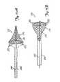
- FIG. 1shows a distal protection device of the present invention in a deployed position.
- FIG. 2shows the distal protection device shown in FIG. 1 in a collapsed position.
- FIG. 3shows an end view of a portion of the distal protection device shown in FIGS. 1 and 2 .
- FIG. 4shows a cross-sectional view of a portion of the distal protection device shown in FIGS. 1-3 in the deployed position.
- FIG. 5shows a second embodiment of the distal protection device according to the present invention in a deployed position.
- FIG. 6shows an end view of the distal protection device shown in FIG. 5 .
- FIG. 7shows a cross-sectional view of the distal protection device shown in FIGS. 5 and 6 in the collapsed position.
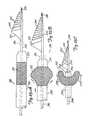
- FIG. 8shows a third embodiment of a distal protection device according to the present invention in a deployed position.
- FIG. 9is a side sectional view of an alternate embodiment illustrating how the expandable members of the present invention are attached to a guidewire.
- FIG. 10is a sectional view taken along section lines 10 .sup.- 10 in FIG. 9 .
- FIGS. 11A and 11Bshow a fourth and fifth embodiment, respectively, of a distal protection device according to the present invention in a deployed position.
- FIG. 12illustrates the operation of a distal protection device in accordance with the present invention.
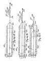
- FIGS. 13A-17Bshow additional embodiments of distal protection devices which expand and collapse based on movement of a mechanical actuator.
- FIGS. 18A-18Dillustrate an additional embodiment of a distal protection device which is deployed and collapsed using a rolling flap configuration.
- FIG. 19illustrates another embodiment in accordance with the present invention in which the protection device is deployed using fluid pressure and a movable collar.
- FIGS. 20A and 20Billustrate another aspect of the present invention in which two longitudinally movable members used to deploy the distal protection device are disconnectably locked to one another.
- FIGS. 21A-21Cillustrate another embodiment in accordance with the present invention in which the protection device is formed with a shape memory alloy frame and an attached filter or mesh mounted to the frame.
- FIGS. 22A-22Cillustrate another embodiment in accordance with the present invention in which the distal protection devices shown in FIGS. 21A-21C are delivered and deployed.
- FIGS. 23A-23Eillustrate another embodiment in accordance with the present invention in which the distal protection devices shown in FIGS. 21A-21C are retrieved.
- FIGS. 24A-24Cillustrate another embodiment in accordance with the present invention in which the distal protection devices shown in FIGS. 21A-21C are retrieved.
- FIG. 1illustrates protection device 10 in a deployed position within the lumen of a blood vessel 12 .
- Protection device 10preferably includes hollow guidewire 14 (or a hypotube having the same general dimensions as a guidewire) having a coil tip 16 , and a capturing assembly 18 .
- Capturing assembly 18in the embodiment shown in FIG. 1 , includes an inflatable and expandable member 20 and mesh 22 .
- expandable member 20is preferably coupled for fluid communication with an inner lumen of guidewire 14 at a distal region of guidewire 14 .
- inflatable member. 20inflates and expands to the position shown in FIG. 1 such that capturing assembly 18 has an outer periphery which approximates the inner periphery of lumen 12 .
- Mesh 22is preferably formed of woven or braided fibers or wires, or a microporous membrane, or other suitable filtering or netting-type material.
- mesh 22is a microporous membrane having holes therein with a diameter of approximately 100 .mu.m.
- Mesh 22can be disposed relative to inflatable member 20 in a number of different ways.
- mesh 22can be formed of a single generally cone-shaped piece which is secured to the outer or inner periphery of inflatable member 20 .
- mesh 22can be formed as a spiral strip which is secured about the outer or inner periphery of inflatable member 20 filling the gaps between the loops of inflatable member 20 .
- mesh 22can be formed of a number of discrete pieces which are assembled onto inflatable member 20 .
- Hollow guidewire 14preferably has a valve 24 coupled in a proximal portion thereof.
- a syringeis preferably connected to the proximal end of guidewire 14 , which preferably includes a fluid hypotube.
- the syringeis used to pressurize the fluid such that fluid is introduced through the lumen of hollow guidewire 14 , through valve 24 , and into inflatable member 20 .
- inflatable member 20Upon being inflated, inflatable member 20 expands radially outwardly from the outer surface of guidewire 14 and carries mesh 22 into the deployed position shown in FIG. 1 .
- capturing assembly, or filter assembly, 18is deployed distally of stenosis 26 so that stenosis 26 can be severed and fragmented, and so the fragments from stenosis 26 are carried by blood flow (indicated by arrow 28 ) into the basket or chamber formed by the deployed filter assembly 18 .
- Filter assembly 18is then collapsed and removed from vessel 12 with the fragments of stenosis 26 contained therein.
- FIG. 2illustrates protection device 10 with filter assembly 18 in the collapsed position. Similar items to those shown in FIG. 1 are similarly numbered.
- FIG. 2illustrates that mesh 22 is easily collapsible with inflatable member 20 .
- fluidis preferably removed from inflatable member 20 through the lumen of hollow guidewire 14 and through two-way valve 24 . This can be done using the syringe to pull a vacuum, or using any other type of suitable fluid removal system.
- Inflatable member 20is preferably formed of a material having some shape memory. Thus, when inflatable member 20 is collapsed, it collapses to approximate the outer diameter of hollow guidewire 14 .
- inflatable member 20is formed of a resilient, shape memory material such that it is inflated by introducing fluid under pressure through the lumen in hollow guidewire 14 into inflatable member 20 . When pressure is released from the lumen in hollow guidewire 14 , inflatable member 20 is allowed to force fluid out from the interior thereof through two-way valve 24 and to resume its initial collapsed position. Again, this results in filter assembly 18 assuming its collapsed position illustrated in FIG. 2 .
- FIG. 3illustrates a view taken from the distal end of device 10 with mesh 22 removed for clarity.
- FIG. 3shows that, when inflatable member 20 is deployed outwardly, mesh 22 (when deployed between the loops of inflatable member 20 ) forms a substantially lumen-filling filter which allows blood to flow therethrough, but which provides a mechanism for receiving and retaining stenosis fragments carried into mesh 22 by blood flow through the vessel.
- FIG. 3also shows that inflatable member 20 preferably has a proximal end portion 29 which is connected to the outer periphery of guidewire 14 .
- end 29need not be connected to guidewire 14 , it is preferably connected using adhesive or any other suitable connection mechanism. By fixedly connecting proximal end portion 29 to guidewire 14 , this increases the stability of the filter assembly 18 upon deployment.
- FIG. 4is a cross-sectional view of a portion of protection device 10 .
- FIG. 4shows protection device 10 with filter assembly 18 in the expanded or deployed position.
- FIG. 4also better illustrates that guidewire 14 is hollow and has a longitudinal lumen 30 extending therethrough. Longitudinal lumen 30 is connected in fluid communication with an interior of inflatable member 20 through aperture 32 which is provided in the wall of guidewire 14 .
- FIG. 4also shows that, in one preferred embodiment, a core wire 34 extends through lumen 30 from a proximal end thereof where it is preferably brazed to a portion of a hypotube which may be connected to the proximal portion of guidewire 14 .
- the core wire 34extends to the distal end of guidewire 14 where it is connected to coil tip 16 .
- coil tip 16is brazed or otherwise welded or suitably connected to the distal portion of core wire 34 .
- FIG. 4further shows that, in the preferred embodiment, inflatable member 20 inflates to a generally helical, conical shape to form a basket opening toward the proximal end of guidewire 14 .
- FIG. 4further illustrates, in the preferred embodiment, mesh 22 has a distal portion 38 which is connected to the exterior surface of guidewire 14 , at a distal region thereof, through adhesive 36 or any other suitable connection mechanism.
- FIG. 5illustrates a second embodiment of a distal protection device 40 in accordance with the present invention.
- Device 40includes hollow guidewire 42 , filter assembly 44 and coil tip 16 .
- Filter assembly 44includes a plurality of inflatable struts 46 and mesh 47 .
- Each strut 46has a distal end 48 and proximal end 50 .
- Inflatable struts 46also have an interior which is coupled in fluid communication, through distal end 48 thereof, with the lumen in hollow guidewire 42 .
- Struts 46are preferably configured such that, upon being inflated, the proximal ends 50 deploy radially outwardly away from the outer surface of hollow guidewire 42 to assume a dimension which approximates the inner dimension of lumen 58 in which they are inserted.
- Mesh 47is deployed either on the outer or inner surface of inflatable struts 46 , such that, when the inflatable struts 46 are deployed radially outwardly, mesh 47 forms a generally conical basket opening toward the proximal end of hollow guidewire 42 .
- mesh 47can be applied to either the outer or the inner surface of struts 46 . It can be applied to struts 46 as one unitary conical piece which is adhered about distal ends 48 of struts 46 using adhesive (or about the distal end of guidewire 42 using adhesive) and secured to the surface of the struts 46 also using adhesive. Alternatively, mesh 47 can be applied to struts 46 in a plurality of pieces which are individually or simultaneously secured to, and extend between, struts 46 .
- FIG. 6is an end view of distal protection device 40 shown in FIG. 5 taken from the distal end of distal protection device 40 .
- mesh 47forms a substantially lumen-filling filter which allows blood to flow therethrough, but which provides a mechanism for receiving and retaining stenosis fragments from stenosis 56 carried into mesh 47 by blood flow through the vessel.
- FIG. 7is a cross-sectional view of a portion of distal protection device 40 shown in FIGS. 5 and 6 .
- FIG. 7shows filter assembly 44 in the collapsed position in which it approximates the outer diameter of guidewire 42 .
- FIG. 7also shows that, in the preferred embodiment, the distal ends 48 of struts 46 are in fluid communication with an inner lumen 52 in hollow guidewire 42 through apertures 54 in the wall of guidewire 42 .
- FIG. 8illustrates another embodiment of a distal protection device 60 in accordance with the present invention.
- Distal protection device 60is similar to those shown in other figures, and similar items are similarly numbered.
- distal protection device 60includes hollow guidewire 63 which has a lumen in fluid communication with an interior of a pair of inflatable struts 62 .
- Inflatable struts 62have an inner surface 64 which is generally concave, or hemispherical, or otherwise appropriately shaped such that it extends about a portion of the outer surface of hollow guidewire 63 .
- Mesh portions 66extend between the inflatable struts 62 so that inflatable struts 62 and mesh portions 66 , when deployed outwardly as shown in FIG. 8 , form a basket shape which opens toward the proximal end of hollow guidewire 63 .
- FIG. 9illustrates another system for attaching inflatable struts to a hollow guidewire for a distal protection device 70 in accordance with the present invention.
- Distal protection device 70is similar to the distal protection devices shown in the previous figures in that a plurality of inflatable struts 72 are provided and preferably have a mesh portion extending therebetween. For the sake of clarity, the mesh portion is eliminated from FIG. 9 . However, it will be understood that, when deployed, distal protection device 70 forms a generally basket-shaped filter assembly which opens toward the proximal end of hollow guidewire 74 .
- hollow guidewire 74has a distal end 75 which is open.
- An endcap 76is disposed about the distal end 75 of hollow guidewire 74 and defines an internal chamber or passageway 78 .
- Endcap 76has a proximal end 80 which has openings therein for receiving the ends of inflatable struts 72 .
- the operatorpressurizes fluid within the lumen of hollow guidewire 74 forcing fluid out through distal end 75 of hollow guidewire 74 , through passageway 78 , and into inflatable struts 72 .
- the operatordraws a vacuum which pulls the fluid back out of inflatable struts 72 , through passageway 78 and, if necessary, into the lumen of hollow guidewire 74 .
- FIG. 10is an end view of endcap 76 taken along lines 10 - 10 in FIG. 9 .
- proximal end 80 of endcap 76preferably includes a first generally central aperture 82 for receiving the distal end of hollow guidewire 74 .
- Aperture 82is sized just larger than, or approximating, the outer diameter of hollow guidewire 74 such that it fits snugly over the distal end 75 of hollow guidewire 74 .
- Endcap 76is then fixedly connected to the distal end 75 of hollow guidewire 74 through a friction fit, a suitable adhesive, welding, brazing, or another suitable connection technique.
- FIG. 10also shows that proximal end 80 of endcap 76 includes a plurality of apertures 84 which are spaced from one another about end 80 . Apertures 84 are sized to receive open ends of inflatable struts 72 . In the preferred embodiment, inflatable struts 72 are secured within apertures 84 using a suitable adhesive, or another suitable connection technique. Also, in the preferred embodiment, spring tip 16 is embedded in, or otherwise suitably connected to, endcap 76 .
- FIGS. 11A and 111show two other preferred embodiments of a distal protection device in accordance with the present invention.
- FIG. 11Ashows distal protection device 90 which includes hollow guidewire 92 having a lumen running therethrough, inflatable member 94 and mesh portion 96 .
- FIG. 11Ashows that inflatable member 94 , when inflated, forms a ring about the outer surface of hollow guidewire 92 .
- the ringhas an inner periphery 98 which is spaced from the outer surface of hollow guidewire 92 substantially about the entire radial periphery of hollow guidewire 92 .
- Mesh portion 96extends between the outer surface of hollow guide 92 and the inner periphery 98 of inflatable member 94 .
- a substantially disc-shaped filter assemblyis provided upon deployment of distal protection device 90 .
- deployment of distal protection device 90is accomplished by providing fluid through the inner lumen of hollow guidewire 92 into an interior of inflatable member 94 which is in fluid communication with the inner lumen of hollow guidewire 92 .
- end 100 of inflatable member 94is coupled to a coupling portion 102 of inflatable member 94 such that stability is added to inflatable member 94 , when it is inflated.
- FIG. 11Billustrates another distal protection device 104 which includes a hollow guidewire 106 and an inflatable member 108 .
- Device 104is similar to distal protection device 90 except that, rather than having only a single inflatable ring upon deployment of distal protection device 104 , a plurality of generally equal-diameter rings are formed into a helix shape.
- distal protection device 104includes a mesh sleeve 110 which extends about the outer or inner surface of the helix formed by inflatable member 108 .
- mesh sleeve 110is connected to the outer surface of hollow guidewire 106 in a region 112 proximate, but distal of, inflatable member 108 .
- distal protection device 104forms a generally basket-shaped filter assembly which opens toward a proximal end of guidewire 106 .
- both distal protection device 90 shown in FIG. 11A and distal protection device 104 shown in FIG. 11Bare preferably collapsible. Therefore, when collapsed, the distal protection devices 90 and 104 preferably have an outer dimension which approximates the outer dimension of hollow guidewires 92 and 106 , respectively. Further, as with the other embodiments, distal protection devices 90 and 104 can either be biased in the deployed or collapsed positions, and deployment and collapse can be obtained either by pulling a vacuum, or pressurizing the fluid within the lumen of the hollow guidewires 92 and 106 .
- FIG. 12illustrates the use of a distal protection device in accordance with the present invention.
- Device 10is shown filtering stenosis fragments from the blood flowing through the lumen of vessel 12 .
- FIG. 12also shows a dilatation device 120 which can be any suitable dilatation device for dilating, cutting, fragmenting, or abrading, portions of stenosis 26 .
- device 120is used in an over-the-wire fashion over hollow guidewire 14 .
- filter assembly 18is first advanced (using guidewire 14 ) distal of stenosis 26 . Then, filter assembly 18 is deployed outwardly to the expanded position.
- Dilatation device 120is then advanced over guidewire 14 to stenosis 26 and is used to fragment or abrade stenosis 26 .
- the fragmentsare received within the basket of filter assembly 18 .
- Filter assembly 18is then collapsed, and filter assembly 18 and dilatation device 120 are removed from vessel 12 .
- dilatation device 120can be removed first and filter assembly 18 is then removed along with guidewire 14 .
- the stenosis removal device 120 used to fragment stenosis 26can be advanced over guidewire 14 . Therefore, the device according to the present invention is dual functioning in that it captures emboli and serves as a guidewire. The present invention does not require adding an additional device to the procedure. Instead, the present invention simply replaces a conventional guidewire with a multi-functional device.
- FIGS. 13A-17Billustrate embodiments of various distal protection devices wherein deployment and contraction of the distal protection device is accomplished through a mechanical push/pull arrangement.
- FIGS. 13A and 13Billustrate a distal protection device 122 .
- FIG. 13Ashows device 122 in an undeployed position and FIG. 13B shows device 122 in a deployed position.
- Distal protection device 122includes a slotted Nitinol tube 124 which has a lumen 126 extending therethrough. Tube 124 has a plurality of slots 128 at a distal region thereof. The distal portion of slots 128 are covered by mesh 130 which, in the preferred embodiment, is a flexible microporous membrane.
- Device 122also preferably includes a mandrel 132 which extends through the inner lumen 126 of tube 124 and is attached to the distal end of tube 124 .
- mandrel 132is attached to the distal end of tube 124 by an appropriate adhesive, brazing, welding, or another suitable connection technique.
- Tube 124also has, on its inner periphery in a proximal region thereof, a plurality of locking protrusions 134 .
- Lock protrusions 134are preferably arranged about a proximal expandable region 136 disposed on mandrel 132 .
- tube 124In order to deploy device 122 into the deployed position shown in FIG. 13B , the operator preferably first advances tube 124 distally of the lesion to be fragmented.
- tube 124has a size on the order of a guidewire, such as a 0.014 inch outer diameter. Therefore, it easily advances beyond the stenosis to be fragmented.
- the operatorthen pushes on the proximal region of tube 124 and pulls on the proximal end of mandrel 132 . This causes two things to happen. First, this causes the struts formed by slots 128 to expand radially outwardly, and carry with them, microporous membrane 130 .
- microporous membrane 130forms a generally basket-shaped filter assembly which opens toward the proximal end of tube 124 .
- proximal expandable member 136expands and engages protrusions 134 . This locks device 122 in the deployed and expanded position.
- the physiciansimply pushes on mandrel 132 and pulls on the proximal end of tube 124 . This causes device 122 to return to the undeployed position shown in FIG. 13A .
- device 122can optionally be provided with a stainless steel proximal hypotube attachment.
- the struts defined by slots 128can be expanded and retracted using a fluid coupling instead of a mandrel.
- the proximal end of tube 124can be coupled to a pressurizable fluid source.
- FIG. 14Aillustrates distal protection device 140 which is similar to that shown in FIGS. 13A and 13B , except that the struts 142 are formed of a metal or polymer material and are completely covered by mesh 144 .
- Mesh 144includes two mesh portions, 146 and 148 .
- Mesh portion 146is proximal of mesh portion 148 on device 140 and is a relatively loose mesh which will allow stenosis fragments to pass therethrough.
- mesh 148is a fairly tight mesh, or a microporous membrane, (or simply loose mesh portion 146 with a microporous membrane or other suitable filter material bonded or cast or otherwise disposed thereover) which does not allow the fragments to pass therethrough and therefore captures and retains the fragments therein.
- the mesh portionscan provide a memory set which, in the relaxed position, is either deployed or collapsed.
- FIG. 14Billustrates a device 150 which is similar to device 140 shown in FIG. 14A , except struts 142 are eliminated and the two mesh portions 146 ′ and 148 ′ are-simply joined together at a region 152 . Also, the two mesh portions 146 ′ and 148 ′ are not two different discrete mesh portions but are formed of the same braided mesh material wherein the braid simply has a different pitch. The wider pitch in region 146 ′ provides a looser mesh, whereas the narrower pitch in region 148 ′ provides a tighter mesh that traps the embolic material.
- FIG. 14Cillustrates a distal protection device 160 which is similar to that shown in FIG. 14A .
- distal protection device 160includes a plurality of struts 162 on a proximal region thereof and a plurality of struts 164 on the distal region thereof.
- Struts 162are spaced further apart than struts 164 about the periphery of protection device 160 . Therefore, struts 162 define openings 166 which are larger than the openings 168 defined by struts 164 and allow stenosis fragments to pass therethrough.
- struts 164have secured to the interior surface thereof a filter or mesh portion 170 . When deployed, filter portion 170 forms a substantially basket-shaped filter device opening toward the proximal region of tube 172 .
- FIG. 15illustrates the operation of another distal protection device 176 .
- Distal protection device 176includes a tube 178 and a push/pull wire 180 .
- Tube 178has, at the distal end thereof, a filter assembly 182 .
- Filter assembly 182includes a plurality of preferably metal struts 184 which have a microporous membrane, or other suitable mesh 186 disposed thereon.
- Tube 178also preferably includes end cap 188 and umbrella-like expansion structure 190 disposed at a distal region thereof.
- Expansion structure 190is connected to the distal region of tube 178 and to metal struts 184 such that, when push/pull wire 180 is pulled relative to tube 178 , expansion member 190 exerts a radial, outwardly directed force on struts 184 causing them to expand radially outwardly relative to the outer surface of tube 178 .
- Thiscauses microporous membrane or mesh 186 to be deployed in a manner opening toward the proximal end of tube 178 to catch embolic material.
- Struts 184can also be formed of an appropriate polymer material.
- FIGS. 16A and 16Billustrate a protection device in accordance with another embodiment of the present invention.
- FIG. 16Aillustrates distal protection device 192 .
- Device 192includes guidewire 194 , actuator wire 196 , and filter assembly 198 .
- Filter assembly 198includes an expandable ring 200 , such as an expandable polymer or metal or other elastic material, which has attached thereto mesh 202 .
- Mesh 202is also attached to guidewire 194 distally of ring 200 .
- Actuator wire 196is attached to sleeve or sheath 204 which is positioned to fit about the outer periphery of expandable ring 200 , when expandable ring 200 is in the collapsed position
- expandable ring 200when sheath 204 is moved distally of expandable ring 200 , expandable ring 200 has shape memory which causes it to expand into the position shown in FIG. 16A .
- sheath 204when sheath 204 is pulled proximally by pulling actuator wire 196 relative to guidewire 194 , sheath 204 collapses ring 200 and holds ring 200 in the collapsed position within sheath 204 .
- Manipulating wires 194 and 196 relative to one anothercauses device 192 to move from the deployed position to the collapsed position, and vice versa.
- FIG. 16Bis similar to device 192 except that, instead of having an expandable ring 200 connected at one point to wire 194 , distal protection device 206 includes expandable member 208 which is formed of an elastic coil section of wire 194 .
- elastic coil section 208has a shape memory which causes it to expand into the generally helical, conical shape shown in FIG. 16B .
- sheath 204is pulled proximally relative to expandable member 208 , this causes sheath 204 to capture and retain expandable member 208 in a collapsed position.
- expandable member 208returns to its expanded position shown in FIG. 16B carrying with it mesh 210 into a deployed position.
- sheath 204is formed of a suitable polymer material and expandable member 208 and expandable ring 200 are preferably formed of Nitinol.
- FIGS. 17A and 17Billustrate the operation of another distal protection device 212 .
- Protection device 212includes guidewire 214 and filter assembly 216 .
- filter assembly 216includes a wire braid portion 218 which extends from a distal region of guidewire 214 proximally thereof.
- Braid portion 218is formed of braided filaments or fibers which have a shape memory causing them to form a deployed, basket-shaped filter, such as that shown in FIG. 17A , in the unbiased position.
- Braided portion 218terminates at its proximal end in a plurality of eyelets 220 .
- One or more cinch wires 222are preferably threaded through eyelets 220 .
- the operatorholds mesh 218 in the collapsed position and inserts protection device 212 distally of the desired stenosis.
- the operatorthen allows cinch wire 222 to move distally relative to guidewire 214 .
- Thisallows mesh 218 to open to the deployed position shown in FIG. 17A which has an outer diameter that approximates the inner diameter of the lumen within which it is disposed.
- Filter assembly 216is then disposed to capture embolic material from blood flowing therethrough. Once the embolic material is captured, the operator again moves cinch wire 222 proximally relative to guidewire 214 to collapse filter assembly 216 and capture and retain the embolic material in filter assembly 216 .
- the device 212is then removed.
- FIG. 17Bshows distal protection device 212 except that in the embodiment shown in FIG. 17B , protection device 212 is not disposed distally of the stenosis, but rather proximally. This results, for example, in an application where the blood flow is proximal of the stenosis rather than distal.
- guidewire 214is preferably hollow and the cinch wire 222 extends through the lumen therein. By pushing on guidewire 214 , a force is exerted on mesh 218 in the distal direction. This causes cinch wire 222 to tightly close the distal opening in filter assembly 216 and to collapse mesh portion 218 .
- mesh portion 218expands and filter assembly 216 is deployed as shown in FIG. 17B .
- FIGS. 18A and 18Billustrate a distal protection device 250 in accordance with another aspect of the present invention.
- Device 250includes inner wire 252 and outer tube 254 .
- inner wire 252is a core wire and outer tube 254 has a lumen 256 therein large enough to accommodate longitudinal movement of inner wire 252 therein.
- inner wire 252has, coupled to its distal end 258 , a spring tip 260 .
- Expandable portion 262has a proximal end 264 which is attached to the distal end 266 of tube 254 . Also, expandable member 262 has a distal end 268 which is attached to the distal end 258 of inner wire 252 .
- Expandable member 262is preferably a mesh or braided material which is coated with polyurethane.
- a distal portion of expandable member 262has a tighter mesh than a proximal portion thereof, or has a microporous membrane or other suitable filtering mechanism disposed thereover.
- expandable member 262is simply formed of a tighter mesh or braided material which, itself, forms the filter.
- FIG. 18Aillustrates device 250 in a collapsed, or insertion position wherein the outer diameter of mesh portion 262 closely approximates the outer diameters of either inner wire 252 or outer tube 254 .
- FIG. 18Billustrates device 250 in the deployed position in which expandable member 262 is radially expanded relative to the collapsed position shown in FIG. 18A .
- the outer tube 254is moved distally with respect to inner wire 252 such that the distal ends 266 and 258 of wires 254 and 252 move longitudinally toward one another. Relative movement of ends 266 and 258 toward one another causes the mesh of expandable member 262 to buckle and fold radially outwardly, forming a cavity 263 having a proximally facing opening.
- the outer diameter of expandable member 262 in the deployed position shown in FIG. 18Bclosely approximates the inner diameter of a vessel within which it is deployed.
- FIG. 18Cillustrates device 250 in a partially collapsed position.
- the distal end 266 of outer tube 254 and the distal end 258 of inner wire 252are moved even closer together than they are as shown in FIG. 18B .
- Thiscauses expandable mesh portion 262 to fold over itself and form a rolling, proximally directed flap 270 .
- mesh portion 262continues to fold over itself such that the rolling flap portion 270 has an outer radial diameter which continues to decrease.
- expandable mesh portion 262continues to fold over itself and to collapse over the outer periphery of outer tube 254 .
- FIG. 18Dillustrates device 250 in a fully collapsed position in which it retains emboli captured therein.
- the distal end 266 of outer tube 254has been advanced as far distally as it can relative to the distal end 258 of inner wire 252 .
- Device 250thus captures any emboli filtered from the vessel within which it was deployed, and can be removed while retaining that embolic material.
- FIG. 19illustrates device 280 which depicts a further aspect in accordance with the present invention.
- Device 280includes outer tube 282 , core wire 284 , transition tube 286 , movable plunger 288 , expandable member 290 , fixed collar 292 and bias member 294 .
- tube 282comprises a proximal hypotube which is coupled to a plunger that selectively provides fluid under pressure through an inflation lumen 296 .
- Inner wire 284is preferably a tapered core wire which terminates at its distal end in a spring coil tip 298 and which is coupled at its proximal end 300 to transition tube 286 .
- Transition tube 286is preferably an outer polymer sleeve either over hypotube 282 , or simply disposed by itself and coupled to a hypotube 282 . Transition tube 286 is capable of withstanding the inflation pressure provided by the fluid delivered through the inflation lumen 296 .
- Movable collar 288is preferably slidably engageable with the interior surface of transition tube 286 and with the exterior surface of core wire 284 , and is longitudinally movable relative thereto.
- Slidable collar 288has, attached at its distal end, bias spring 294 which is preferably coiled about core wire 284 and extends to fixed collar 292 .
- Fixed collar 292is is preferably fixedly attached to the exterior surface of a distal portion of core wire 284 .
- Expandable member 290is preferably formed, at a proximal portion thereof, of either discrete struts, or another suitable frame (such as a loose mesh) which allows blood and embolic material to flow therethrough.
- the proximal end 302 of expandable member 290is coupled to a distal region of movable collar 288 .
- the distal portion of expandable member 290is preferably formed of a filtering material which is suitable for allowing blood flow therethrough, but which will capture embolic material being carried by the blood.
- spring 294is biased to force collars 288 and 292 away from one another.
- collar 288retracts within transition tube 286 pulling expandable member 290 into a collapsed position about core wire 284 .
- the operatorin order to deploy collapsible member 290 as shown in FIG. 19 , the operator preferably actuates a plunger (not shown) which delivers pressurized fluid through lumen 296 .
- the pressurized fluidenters transition tube 286 and travels about the outer periphery of inner core wire 284 , thus forcing movable collar 288 to move distally along core wire 284 .
- Thisovercomes the spring force exerted by spring 294 thus causing collars 288 and 292 to move toward one another, relatively.
- This motioncauses expandable member 290 to buckle and expand outwardly to the deployed position shown in FIG. 19 .
- Expandable member 290is collapsed by releasing the pressure applied through lumen 296 (i.e., by causing the plunger to move proximally). This allows spring 294 to again urge collars 288 and 292 away from one another to collapse expandable member 290 .
- the frame supporting expandable member 290is imparted with a memory (such as a heat set, or a thermally responsive material which assumes a memory upon reaching a transition temperature) such that the resting state of the frame supporting expandable member 290 is in a collapsed position. This eliminates the need for spring 294 .
- the expandable member 290in that preferred embodiment, is expanded using the hydraulic pressure provided by the pressurized fluid introduced through lumen 296 , and it is collapsed by simply allowing the memory in expandable member 290 to force fluid from transition tube 286 back through lumen 296 .
- FIGS. 20A and 20Billustrate another aspect in accordance with the present invention.
- a device 310includes a mesh portion 312 supported by a frame 314 . Expansion of frame 314 to the radially expanded position shown in FIG. 20A is driven by an expandable member, such as a balloon 316 which is coupled to frame 314 . Balloon 316 is coupled to a distal end of a distal hypotube 318 , which is formed of a suitable material, such as nitinol. It should be noted that the distal tip of hypotube 318 includes a spring tip 320 .
- Distal hypotube 318is shown coupled to a proximal hypotube 322 which has a tapered portion 324 therein.
- proximal hypotube 322is formed of a suitable material, such as stainless steel.
- a plunger 326is longitudinally movable within the lumen of both proximal hypotube 322 and distal hypotube 318 .
- Frame 314 , and consequently mesh portion 312are deployed by the operator moving plunger 326 distally within the lumens of hypotubes 318 and 322 .
- Thiscauses pressurized fluid to enter balloon 316 , thereby inflating balloon 316 and driving deployment of frame 314 and mesh 312 .
- the operatorpreferably moves plunger 326 proximally within the lumens of tubes 318 and 322 to withdraw fluid from within balloon 316 .
- mesh 312 or frame 314can have a memory set which is either in the inflated or collapsed position such that the operator need only affirmatively move frame 314 and mesh 312 to either the deployed or collapsed position, whichever is opposite of the memory set.
- device 310includes a locking region 328 .
- FIG. 20Billustrates locking region 328 in greater detail.
- FIG. 20Billustrates that, in locking region 328 , plunger 326 has a plurality of grooves 330 formed in the outer radial surface thereof.
- FIG. 20Billustrates that one of hypotubes 318 or 322 has an inwardly projecting portion 332 .
- inwardly projecting portion 332includes an inwardly extending, deflectable, annular rim which extends inwardly from either hypotube 318 or 322 .
- the inwardly projecting portion 332includes a plurality of discrete fingers which extend inwardly from one of hypotubes 318 or 322 and which are angularly displaced about the interior periphery of the corresponding hypotube 318 or 322 .
- inwardly projecting portion 332rides along the exterior periphery of plunger 326 until it encounters one of grooves 330 . Then, inwardly projecting portion 332 snaps into the groove 330 to lock plunger 326 longitudinally relative to tubes 318 and 322 .
- both inwardly projecting portions 332 and grooves 330are formed such that, when gentle pressure is exerted by the operator on plunger 326 relative to hypotubes 318 and 322 , projection portions 332 follow the contour of grooves 330 up and out of grooves 330 so that plunger 326 can again be freely moved within the lumens of hypotubes 318 and 322 .
- the relative interaction between projecting portions 332 and grooves 330provides a ratcheting type of operation wherein plunger 326 can be releasably locked into one of a plurality longitudinal positions relative hypotubes 318 and 322 , since a plurality of grooves 330 are provided.
- Plunger 326can be moved back and forth longitudinally within the lumens of hypotubes 318 and 322 in a ratcheting manner and can be locked into one of a plurality of relative longitudinal positions because there are a plurality of grooves 330 in the exterior of plunger 326 . It should also be noted, however, that in another preferred embodiment, a plurality of sets of inwardly projecting portions 332 are provided along the inner longitudinal surface of hypotubes 318 and/or 322 . In that case, only a single groove 330 needs to be formed in the exterior surface of plunger 326 ; and the same type of ratcheting locking operation is obtained.
- hypotubes 318 and 322are tapered. This allows device 310 to maintain increased flexibility. It should also be noted that, in the preferred embodiment, hypotubes 318 and 322 are preferably sized as conventional guidewires.
- FIG. 21Aillustrates a protection device in accordance with another embodiment of the present invention.
- FIG. 21Aillustrates distal protection device 340 .
- Device 340is similar to devices 192 and 206 shown in FIGS. 16A and 16B .
- device 340includes hoop-shaped frame 342 , filter portion 344 , and wire 346 .
- Hoop-shaped frame 342is preferably a self-expanding frame formed of a wire which includes a shape memory alloy.
- hoop-shaped frame 342is formed of a nitinol wire having a diameter in a range of approximately 0.002-0.004 inches.
- Filter portion 344is preferably formed of a polyurethane material having holes therein such that blood flow can pass through filter 344 , but emboli (of a desired size) cannot pass through filter 344 but are retained therein.
- filter material 344is attached to hoop-shaped frame 342 with a suitable, commercially available adhesive.
- filter 344has a proximal portion thereof folded over hoop-shaped frame 342 , and the filter material is attached itself either with adhesive, by stitching, or by another suitable connection mechanism, in order to secure it about hoop-shaped frame 342 .
- This connectionis preferably formed by a suitable adhesive or other suitable connection mechanism.
- the distal end of filter 344is preferably attached about the outer periphery of wire 346 , proximate coil tip 348 on wire 346 .
- filter 344is approximately 15 mm in longitudinal length, and has a diameter at its mouth (defined by hoop-shaped frame 342 ) of a conventional size (such as 4.0 mm, 4.5 mm, 5 mm, 5.5 mm, or 6 mm). Of course, any other suitable size can be used as well.
- a conventional sizesuch as 4.0 mm, 4.5 mm, 5 mm, 5.5 mm, or 6 mm.
- any other suitable sizecan be used as well.
- filter 344is formed of a polyurethane material with the holes laser drilled therein.
- the holesare preferably approximately 100 .mu.m in diameter.
- filter 344can also be a microporous membrane, a wire or polymer braid or mesh, or any other suitable configuration.
- Wire 346is preferably a conventional stainless-steel guidewire having conventional guidewire dimensions.
- wire 346is a solid core wire having an outer diameter of approximately 0.014 inches and an overall length of up to 300 cm.
- wire 346has a distal end 350 , in a region proximate filter 344 , which tapers from an outer diameter at its proximal end which is the same as the outer diameter of the remainder of wire 346 , to an outer diameter of approximately 0.055 inches at its distal end.
- guidewire 346is preferably formed of stainless steel 304 .
- guidewires having an outer diameter of approximately 0.018 inchesmay also be used.
- different dimensionsmay also be used, such as outer diameters of approximately 0.010 inches to 0.014 inches.
- wire 346will vary with application. Applications involving neural vasculature will require the use of a smaller guidewire, while other applications will require the use of a larger guidewire.
- wire 346can be replaced by a hollow guidewire, or hypotube of similar, or other suitable dimensions.
- radiopaque loaded powdercan be used to form a polyurethane sheath which is fitted over wire 346 or hoop 342 , or which is implemented in filter 344 .
- hoop 342 and wire 346can be gold plated in order to increase radiopacity.
- marker bandscan be used on wire 346 or filter 344 to increase the radiopacity of the device.
- hoop 342(and thus filter 344 ) is preferably collapsed to a radially contracted position which more closely approximates the outer diameter of wire 346 . Methods of performing this contraction are described later in the specification.
- wire 346is manipulated to position hoop 342 and filter 344 distal of a restriction to be treated. Then, the restraining force which is used to restrain hoop 342 in the predeployment, low profile position is removed, and the superelastic properties of nitinol hoop 342 (or the shape memory properties of another shape memory alloy) are utilized in allowing hoop 342 to assume its shape memory position. This causes hoop 342 to define a substantially lumen filling mouth to filter 344 which is positioned distal of the restriction to be treated.
- a suitable dilatation deviceis then advanced over wire 346 and is used to treat the vascular restriction. Emboli which are carried by blood flow distal of the restriction are captured by filter 344 . After the dilatation procedure, filter 344 , along with the emboli retained therein, are retrieved from the vasculature. Various retrieval procedures and devices are described later in the specification.
- hoop-shaped frame 342By allowing hoop-shaped frame 342 to be unattached to wire 346 , and only connected to wire 346 through filter 344 (or other super structure used to support filter 344 ), wire 346 is allowed to substantially float within hoop 342 .
- This configurationprovides some advantages. For instance, hoop 342 can better follow the vasculature without kinking or prolapsing (i.e., without collapsing upon itself). Thus, certain positioning or repositioning of filter 344 can be accomplished with less difficulty.
- FIG. 21Billustrates a protection device 352 in accordance with another embodiment of the present invention.
- Protection device 352is similar to protection device 340 , and similar items are similarly numbered. However, rather than having simply a hoop-shaped frame 342 to support filter 344 , and drive filter 344 into its expanded and deployed position, device 352 includes frame 354 which includes a hoop-shaped portion 356 , and a pair of tails 358 and 360 .
- Tails 358 and 360extend proximally from hoop-shaped portion 356 to an attachment region 362 .
- tails 358 and 360are attached to wire 346 at attachment region 362 by soldering, welding, brazing, adhesive, or any other suitable attachment mechanism.
- attachment sleeve 364formed of a weldable material, is attached at its inner periphery to tails 358 and 360 . Sleeve 364 is then attached, using welding or brazing, to wire 346 .
- tails 358 and 360frame 354 is directly connected to wire 346 .
- tails 358 and 360are provided so that the point of attachment of frame 354 to wire 346 is located several millimeters proximal of hoop-shaped portion 356 . This provides some additional structural integrity to frame 354 , but still allows frame 354 to substantially float about wire 346 in the region of hoop-shaped frame portion 356 .
- FIG. 21Cillustrates a protection device 366 in accordance with another embodiment of the present invention.
- Protection device 366is similar to protection devices 340 and 352 shown in FIGS. 21A and 21B , and similar items are similarly numbered.
- device 366includes hoop-shaped frame 368 .
- Frame 368is similar to frame 342 shown in FIG. 21A .
- hoop 368does not allow wire 346 to float freely therein. Instead, hoop 368 is directly attached to wire 346 at attachment point 370 . This causes hoop-shaped frame 368 and filter 344 to reside eccentrically about wire 346 .
- FIGS. 22A-22Cillustrate one preferred embodiment for delivering one of devices 340 , 352 and 366 .
- device 352is illustrated in FIGS. 22A-22C .
- FIG. 22Aillustrates delivery device 372 .
- delivery device 372includes proximal hub 374 , shaft 376 , and distal retaining section 378 .
- device 372also includes marker band 380 .
- delivery device 372is similar to a conventional balloon catheter in that proximal hub 374 is a conventional hub, and shaft 376 is a conventional balloon catheter shaft.
- distal retaining section 378is preferably a conventional angioplasty balloon having an inflated diameter of approximately 1.5-2.0 millimeters, but having its distal end cutoff such that the distal end 382 of balloon 378 is open.
- hoop-shaped frame 354Prior to insertion of device 372 into the vasculature, hoop-shaped frame 354 is retracted into its low profile deployment position and is withdrawn through end 382 into balloon 378 . Then, the distal end of balloon 378 is exposed to heat to heat shrink or heat set the distal end of balloon 378 around the radially retracted device 352 .
- Device 372including device 352 , is then inserted in the vasculature either through a preplaced guide catheter, along with a guide catheter, or simply without a guide catheter utilizing coil tip 348 .
- distal protection device 352is then removed from within heat collapsed balloon 378 .
- the physiciansimply accomplishes longitudinal movement of wire 346 relative to catheter 376 .
- the physicianmay simply hold wire 346 longitudinally in place and withdraw catheter 376 proximally relative to wire 346 by pulling on hub 374 . This causes balloon 378 to move proximally relative to device 352 , and thereby to expose device 352 to the vasculature.
- FIG. 22Billustrates another preferred embodiment for removing device 352 from within balloon 378 .
- syringe 384which contains fluid, is inserted into coupling 386 in hub 374 .
- the physicianthen introduces pressurized fluid into the lumen of catheter 376 .
- the pressurized fluidadvances down the lumen of catheter 376 to the distal end where it encounters collapsed balloon 378 .
- the pressure exerted on balloon 378 by the pressurized fluidcauses balloon 378 to open radially.
- the physicianwithdraws catheter 376 relative to device 352 thereby exposing device 352 to the vasculature.
- device 352assumes its shape memory position in the vasculature, as illustrated in FIG. 22C .
- device 352substantially forms a lumen-filling basket or filter which allows blood to pass distally therethrough, but which retains or captures embolic material carried by the blood flow.
- the physicianthen simply removes device 372 from the vasculature, leaving device 352 in place during subsequent procedures.
- shaft 376includes a predefined slit or score from a region just proximal of marker band 380 to, or through, hub 374 . Thus, as the physician removes device 372 , it can be peeled away from device 352 .
- device 372can be provided with an aperture in shaft 376 near its distal end.
- the proximal end of wire 346will thus lie outside of shaft 376 .
- Wire 346can enter shaft 376 through the aperture and extend through the distal end of shaft 376 . This also facilitates easier withdrawal of device 372 over wire 346 .
- FIGS. 23A-23Eillustrate one preferred embodiment for retrieving one of the devices 340 , 352 and 366 described in FIGS. 21A-21C .
- FIG. 23Aillustrates retrieval device 388 .
- Retrieval device 388is preferably formed of proximal shaft 390 , mesh portion 392 , and end cap 394 . Items 390 , 392 and 394 preferably each have lumens therein to define a passageway for receiving wire 346 .
- wire 346may optionally be provided with an positive stop 396 (which can be embodied as a radiopaque marker band)
- Optional stop 396may also simply be an annular ring attached to wire 346 proximate to filter 344 , or may be any other suitable stop.
- Proximal shaft 390is preferably simply a polymer or nitinol tube sized and configured to track over wire 346 .
- End cap 394is also preferably formed to track over wire 346 , but also contains radiopaque material to serve as a distal marker band for retrieval device 388 .
- Mesh 392is preferably a braid or mesh formed of wire or polymer material having sufficient flexibility that it can be deflected as described below.
- Mesh 392preferably has a proximal end coupled to proximal shaft 390 , by adhesive, welding, or other suitable attachment mechanisms.
- Mesh 392also preferably includes a distal end connected to end cap 394 , also by a suitable connection mechanism.
- device 388In order to retrieve filter 344 , which likely contains embolic material, device 388 is inserted in the low profile position shown in FIG. 23A , over wire 346 , to a position proximate filter 344 . Then, device 388 is advanced toward filter 344 , until end cap 394 abuts positive stop 396 , or the hoop-shaped frame 354 . Continued advancement of proximal shaft 390 relative to wire 346 causes compression of mesh 392 . This results in a radial expansion of an intermediate portion of mesh 392 (between the proximal and distal ends of mesh 392 ). The radial expansion of mesh portion 392 is illustrated in FIG. 23B .
- the intermediate portion of mesh 392is configured to bend over on itself such that it is axially displaced toward filter 344 , in the direction generally indicated by arrows 398 in FIG. 23C .
- mesh 392is sized and configured such that, with continued advancement OL proximal shaft 390 relative to wire 346 , this action continues as shown in FIGS. 23D and 23E until the intermediate portion of mesh 392 encompasses at least the mouth of filter 344 .
- the intermediate portion of mesh 392when driven as described above, engages and contracts the mouth of filter 344 to a lower profile position, such as that shown in FIG. 23E .
- mesh 392is sized and configured to substantially engulf the entire filter 344 .
- device 388are simply withdrawn from the vasculature.
- devices 388 and 352are simply withdrawn either into the guide catheter and the guide catheter is removed with those devices, simultaneously, or devices 388 and 352 are removed from the guide catheter prior to removal of the guide catheter.
- devices 388 and 352are simply removed from the vasculature simultaneously.
- a second actuation tube or wirecan also be provided which is attached to end cap 394 , and which extends back through the lumen in proximal tube 390 and is longitudinally movable relative to proximal shaft 390 .
- the actuation wire or elongate membercan be used to pull cap 394 closer to the distal portion of proximal shaft 390 in order to accomplish the action illustrated in FIGS. 23A-23E .
- FIGS. 18A-18Dillustrate the mesh portion folded proximally rather than distally.
- FIGS. 24A-24Cillustrate another preferred embodiment in accordance with the present invention, for retrieving any of the distal protection devices 340 , 352 or 366 shown in FIGS. 21A-21C .
- the distal protection devices 340 , 352 or 366 shown in FIGS. 21A-21CFor the sake of clarity, only device 352 is illustrated in FIGS. 24A-24C .
- FIG. 24Aillustrates retrieval device 400 .
- Retrieval device 400preferably includes retrieval sheath 402 , proximal locking device 404 , dilator sheath 405 , and nose cone 406 .
- retrieval sheath 402is preferably formed of polyether block amide (PEBAX) material having an outer diameter of approximately six French (i.e., approximately 2 mm) and having a shore D hardness of approximately 40.
- retrieval sheath 402preferably has a wall thickness of approximately 0.004 inches.
- Dilator sheath 405 , and nose cone 406are preferably formed of low density polyethylene, or high density polyethylene.
- Sheath 405preferably has an outer diameter which is approximately equal to the inner diameter of sheath 402 .
- the inner diameter of sheath 405 and nose cone 406is preferably just large enough to fit over, and track over, wire 346 .
- Nose cone 406preferably has a proximal portion which is either attached to, or formed integrally with, sheath 405 .
- the outer diameter of the proximal portion of nose cone 406is also approximately the same as the outer diameter of sheath 405 .
- nose cone 406also preferably has a distal portion which tapers, or reduces along preferably a smooth curve, to an outer diameter which terminates at the inner diameter of nose cone 406 .
- Proximal locking device 404is preferably any suitable, and commercially available, locking device which can be configured to lock dilator sheath 405 to guidewire 346 .
- device 400is preferably advanced over guidewire 346 to a position shown in FIG. 24B , in which the distal portion of nose cone 406 is closely proximate, or adjacent to, either optional stop 396 or the mouth of filter 344 . Then, proximal locking device 404 is actuated to lock dilator sheath 405 to wire 346 so that wire 346 and dilator sheath 405 (as well as nose cone 406 ) can be moved as a unitary piece.
- wire 346(and hence dilator sheath 405 and nose cone 406 ) are withdrawn longitudinally relative to retrieval sheath 402 .
- Thiscauses the mouth of filter 344 to enter within the distal opening in retrieval sheath 402 .
- wire 346 , dilator sheath 405 and nose cone 406can be withdrawn further into sheath 402 such that the entire filter 344 , and wire tip 348 , are disposed within the lumen of sheath 402 .
- device 352is configured to be removed from the vasculature. This can be accomplished by either removing dilator sheath 405 , nose cone 406 and device 352 as a unitary piece, leaving sheath 402 in place for later removal, or by removing sheath 402 with the remainder of the system, either through a guide catheter or simply through the vasculature, simultaneously. Also, where a guide catheter is used, device 352 and device 400 can be removed through the guide catheter leaving the guide catheter in place, or the guide catheter can be removed simultaneously with the other devices 352 and 400 .
- all of the devices according to the present inventioncan optionally be coated with an antithrombotic material, such as heparin (commercially available under the tradename Duraflow from Baxter), to inhibit clotting.
- an antithrombotic materialsuch as heparin (commercially available under the tradename Duraflow from Baxter), to inhibit clotting.
- the superelastic properties of nitinolare used to form a frame at least in the area of the mouth of the distal protection filter.
- the distal protection devicecan be deployed, retrieved, and re-deployed any number of times without incurring plastic deformation.
- various deployment and retrieval techniques and systemsare provided which address various problems associated with such systems.
Landscapes
- Health & Medical Sciences (AREA)
- Life Sciences & Earth Sciences (AREA)
- Engineering & Computer Science (AREA)
- Public Health (AREA)
- Surgery (AREA)
- Biomedical Technology (AREA)
- Heart & Thoracic Surgery (AREA)
- Vascular Medicine (AREA)
- Veterinary Medicine (AREA)
- Animal Behavior & Ethology (AREA)
- General Health & Medical Sciences (AREA)
- Transplantation (AREA)
- Cardiology (AREA)
- Orthopedic Medicine & Surgery (AREA)
- Nuclear Medicine, Radiotherapy & Molecular Imaging (AREA)
- Oral & Maxillofacial Surgery (AREA)
- Medical Informatics (AREA)
- Molecular Biology (AREA)
- Surgical Instruments (AREA)
Abstract
Description
Claims (7)
Priority Applications (1)
| Application Number | Priority Date | Filing Date | Title |
|---|---|---|---|
| US11/314,775US7780696B2 (en) | 1997-03-06 | 2005-12-21 | Distal protection device and method |
Applications Claiming Priority (8)
| Application Number | Priority Date | Filing Date | Title |
|---|---|---|---|
| US08/810,825US5814064A (en) | 1997-03-06 | 1997-03-06 | Distal protection device |
| US08/813,794US5827324A (en) | 1997-03-06 | 1997-03-06 | Distal protection device |
| US08/943,358US6001118A (en) | 1997-03-06 | 1997-10-03 | Distal protection device and method |
| US09/409,497US6245089B1 (en) | 1997-03-06 | 1999-09-30 | Distal protection device and method |
| US09/735,332US20010044632A1 (en) | 1997-03-06 | 2000-12-12 | Distal protection device and method |
| US10/160,450US6663652B2 (en) | 1997-03-06 | 2002-05-30 | Distal protection device and method |
| US10/650,304US20040106944A1 (en) | 1997-03-06 | 2003-08-28 | Distal protection device and method |
| US11/314,775US7780696B2 (en) | 1997-03-06 | 2005-12-21 | Distal protection device and method |
Related Parent Applications (1)
| Application Number | Title | Priority Date | Filing Date |
|---|---|---|---|
| US10/650,304ContinuationUS20040106944A1 (en) | 1997-03-06 | 2003-08-28 | Distal protection device and method |
Publications (2)
| Publication Number | Publication Date |
|---|---|
| US20060100662A1 US20060100662A1 (en) | 2006-05-11 |
| US7780696B2true US7780696B2 (en) | 2010-08-24 |
Family
ID=27123778
Family Applications (1)
| Application Number | Title | Priority Date | Filing Date |
|---|---|---|---|
| US11/314,775Expired - Fee RelatedUS7780696B2 (en) | 1997-03-06 | 2005-12-21 | Distal protection device and method |
Country Status (3)
| Country | Link |
|---|---|
| US (1) | US7780696B2 (en) |
| EP (1) | EP0934092A4 (en) |
| WO (1) | WO1998039053A1 (en) |
Cited By (118)
| Publication number | Priority date | Publication date | Assignee | Title |
|---|---|---|---|---|
| US20050237364A1 (en)* | 2004-04-26 | 2005-10-27 | Hirosumi Ito | Printed wiring board and electric device using the same |
| US20070299466A1 (en)* | 2004-11-24 | 2007-12-27 | Ravish Sachar | Percutaneous Transluminal Angioplasty Device With Integral Embolic Filter |
| US20100063533A1 (en)* | 2005-12-30 | 2010-03-11 | C.R. Bard Inc. | Embolus blood clot filter with floating filter basket |
| US20100106182A1 (en)* | 2008-10-22 | 2010-04-29 | Patel Udayan G | Angioplasty device with embolic filter |
| US20100179567A1 (en)* | 2009-01-09 | 2010-07-15 | Abbott Vascular Inc. | Closure devices, systems, and methods |
| US20120065728A1 (en)* | 2010-05-10 | 2012-03-15 | Heart Leaflet Technologies, Inc. | Stentless Support Structure |
| US8236026B2 (en) | 2000-12-07 | 2012-08-07 | Integrated Vascular Systems, Inc. | Closure device and methods for making and using them |
| US8313497B2 (en) | 2005-07-01 | 2012-11-20 | Abbott Laboratories | Clip applier and methods of use |
| US8323312B2 (en) | 2008-12-22 | 2012-12-04 | Abbott Laboratories | Closure device |
| US8398676B2 (en) | 2008-10-30 | 2013-03-19 | Abbott Vascular Inc. | Closure device |
| US8398656B2 (en) | 2003-01-30 | 2013-03-19 | Integrated Vascular Systems, Inc. | Clip applier and methods of use |
| US8469995B2 (en) | 2002-06-04 | 2013-06-25 | Abbott Vascular Inc. | Blood vessel closure clip and delivery device |
| WO2013106146A1 (en) | 2012-01-10 | 2013-07-18 | Cook Medical Technologies Llc | Object capture device |
| US8529587B2 (en) | 2003-01-30 | 2013-09-10 | Integrated Vascular Systems, Inc. | Methods of use of a clip applier |
| US8556930B2 (en) | 2006-06-28 | 2013-10-15 | Abbott Laboratories | Vessel closure device |
| US8579932B2 (en) | 2002-02-21 | 2013-11-12 | Integrated Vascular Systems, Inc. | Sheath apparatus and methods for delivering a closure device |
| US8585836B2 (en) | 2002-12-31 | 2013-11-19 | Integrated Vascular Systems, Inc. | Methods for manufacturing a clip and clip |
| US8590760B2 (en) | 2004-05-25 | 2013-11-26 | Abbott Vascular Inc. | Surgical stapler |
| US8597325B2 (en) | 2000-12-07 | 2013-12-03 | Integrated Vascular Systems, Inc. | Apparatus and methods for providing tactile feedback while delivering a closure device |
| US8603116B2 (en) | 2010-08-04 | 2013-12-10 | Abbott Cardiovascular Systems, Inc. | Closure device with long tines |
| US8672953B2 (en) | 2007-12-17 | 2014-03-18 | Abbott Laboratories | Tissue closure system and methods of use |
| US8690910B2 (en) | 2000-12-07 | 2014-04-08 | Integrated Vascular Systems, Inc. | Closure device and methods for making and using them |
| US8728119B2 (en) | 2001-06-07 | 2014-05-20 | Abbott Vascular Inc. | Surgical staple |
| US8758396B2 (en) | 2000-01-05 | 2014-06-24 | Integrated Vascular Systems, Inc. | Vascular sheath with bioabsorbable puncture site closure apparatus and methods of use |
| US8758400B2 (en) | 2000-01-05 | 2014-06-24 | Integrated Vascular Systems, Inc. | Closure system and methods of use |
| US8758398B2 (en) | 2006-09-08 | 2014-06-24 | Integrated Vascular Systems, Inc. | Apparatus and method for delivering a closure element |
| US8758399B2 (en) | 2010-08-02 | 2014-06-24 | Abbott Cardiovascular Systems, Inc. | Expandable bioabsorbable plug apparatus and method |
| US8784447B2 (en) | 2000-09-08 | 2014-07-22 | Abbott Vascular Inc. | Surgical stapler |
| US8808310B2 (en) | 2006-04-20 | 2014-08-19 | Integrated Vascular Systems, Inc. | Resettable clip applier and reset tools |
| US8820602B2 (en) | 2007-12-18 | 2014-09-02 | Abbott Laboratories | Modular clip applier |
| US8821534B2 (en) | 2010-12-06 | 2014-09-02 | Integrated Vascular Systems, Inc. | Clip applier having improved hemostasis and methods of use |
| US20140277013A1 (en)* | 2013-03-15 | 2014-09-18 | Microvention, Inc. | Multi-Component Obstruction Removal System And Method |
| US8858594B2 (en) | 2008-12-22 | 2014-10-14 | Abbott Laboratories | Curved closure device |
| US8893947B2 (en) | 2007-12-17 | 2014-11-25 | Abbott Laboratories | Clip applier and methods of use |
| US8905937B2 (en) | 2009-02-26 | 2014-12-09 | Integrated Vascular Systems, Inc. | Methods and apparatus for locating a surface of a body lumen |
| US8926656B2 (en) | 2003-01-30 | 2015-01-06 | Integated Vascular Systems, Inc. | Clip applier and methods of use |
| US8926633B2 (en) | 2005-06-24 | 2015-01-06 | Abbott Laboratories | Apparatus and method for delivering a closure element |
| US8956388B2 (en) | 2000-01-05 | 2015-02-17 | Integrated Vascular Systems, Inc. | Integrated vascular device with puncture site closure component and sealant |
| US9089311B2 (en) | 2009-01-09 | 2015-07-28 | Abbott Vascular Inc. | Vessel closure devices and methods |
| US9089674B2 (en) | 2000-10-06 | 2015-07-28 | Integrated Vascular Systems, Inc. | Apparatus and methods for positioning a vascular sheath |
| US9149276B2 (en) | 2011-03-21 | 2015-10-06 | Abbott Cardiovascular Systems, Inc. | Clip and deployment apparatus for tissue closure |
| US9173644B2 (en) | 2009-01-09 | 2015-11-03 | Abbott Vascular Inc. | Closure devices, systems, and methods |
| US9282965B2 (en) | 2008-05-16 | 2016-03-15 | Abbott Laboratories | Apparatus and methods for engaging tissue |
| US9314230B2 (en) | 2009-01-09 | 2016-04-19 | Abbott Vascular Inc. | Closure device with rapidly eroding anchor |
| US9332976B2 (en) | 2011-11-30 | 2016-05-10 | Abbott Cardiovascular Systems, Inc. | Tissue closure device |
| WO2016089451A1 (en)* | 2014-12-02 | 2016-06-09 | Legacy Ventures LLC | Clot retrieval system |
| US9364209B2 (en) | 2012-12-21 | 2016-06-14 | Abbott Cardiovascular Systems, Inc. | Articulating suturing device |
| US20160193457A1 (en)* | 2015-01-05 | 2016-07-07 | Boston Scientific Scimed, Inc. | Flexible member for resisting retrograde flow |
| US9414824B2 (en) | 2009-01-16 | 2016-08-16 | Abbott Vascular Inc. | Closure devices, systems, and methods |
| US9414820B2 (en) | 2009-01-09 | 2016-08-16 | Abbott Vascular Inc. | Closure devices, systems, and methods |
| US9463035B1 (en)* | 2015-09-28 | 2016-10-11 | GW Medical LLC | Mechanical thrombectomy apparatuses and methods |
| US9486191B2 (en) | 2009-01-09 | 2016-11-08 | Abbott Vascular, Inc. | Closure devices |
| US9579116B1 (en) | 2015-08-06 | 2017-02-28 | Kp Medcure, Inc. | Axial lengthening thrombus capture system |
| US9579091B2 (en) | 2000-01-05 | 2017-02-28 | Integrated Vascular Systems, Inc. | Closure system and methods of use |
| US9585647B2 (en) | 2009-08-26 | 2017-03-07 | Abbott Laboratories | Medical device for repairing a fistula |
| US9744024B2 (en) | 2015-08-06 | 2017-08-29 | Kp Medcure, Inc. | Axial lengthening thrombus capture system |
| US20180103971A1 (en)* | 2015-06-16 | 2018-04-19 | Terumo Kabushiki Kaisha | Medical device and treatment method |
| US9999493B2 (en) | 2015-08-06 | 2018-06-19 | Kp Medcure, Inc. | Axial lengthening thrombus capture system |
| US10292805B2 (en) | 2015-01-23 | 2019-05-21 | Contego Medical, Llc | Interventional device having an integrated embolic filter and associated methods |
| WO2019232079A1 (en)* | 2018-05-30 | 2019-12-05 | eLum Technologies, Inc. | Integrated thrombectomy and filter device and methods of use |
| US10512478B2 (en) | 2016-04-25 | 2019-12-24 | Stryker Corporation | Clot-engulfing mechanical thrombectomy apparatuses |
| US10517624B2 (en)* | 2016-06-03 | 2019-12-31 | Stryker Corporation | Inverting thrombectomy apparatuses and methods |
| US10548619B2 (en) | 2011-04-29 | 2020-02-04 | Michael P. Wallace | Selective spinal tissue removal apparatus and method |
| US10610245B2 (en) | 2016-09-12 | 2020-04-07 | Stryker Corporation | Self-rolling thrombectomy apparatuses and methods |
| US10624659B2 (en) | 2018-03-12 | 2020-04-21 | Xtract Medical, Inc. | Devices and methods for removing material from a patient |
| US10779843B2 (en) | 2017-11-09 | 2020-09-22 | Stryker Corporation | Inverting thrombectomy apparatuses having enhanced tracking |
| US10835269B1 (en) | 2018-09-10 | 2020-11-17 | Stryker Corporation | Inverting thrombectomy apparatuses and methods of use |
| US10842513B2 (en) | 2016-04-25 | 2020-11-24 | Stryker Corporation | Methods for advancing inverting mechanical thrombectomy apparatuses in the vasculature |
| US10888343B2 (en) | 2016-04-25 | 2021-01-12 | Stryker Corporation | Anti-jamming and macerating thrombectomy apparatuses and methods |
| US11007045B2 (en) | 2016-03-02 | 2021-05-18 | C.R. Bard, Inc. | Embolic protection basket apparatus |
| EP3827765A1 (en)* | 2019-11-27 | 2021-06-02 | Neuravi Limited | An aspiration catheter, systems, and methods thereof |
| US11076876B2 (en) | 2014-06-30 | 2021-08-03 | Neuravi Limited | System for removing a clot from a blood vessel |
| US11096705B2 (en)* | 2016-08-29 | 2021-08-24 | Terumo Kabushiki Kaisha | Medical device and procedure method |
| US11103265B2 (en) | 2018-05-14 | 2021-08-31 | Stryker Corporation | Inverting thrombectomy apparatuses and methods of use |
| US11253291B2 (en) | 2018-09-10 | 2022-02-22 | Stryker Corporation | Laser slotted grabbing device |
| US11311304B2 (en) | 2019-03-04 | 2022-04-26 | Neuravi Limited | Actuated clot retrieval catheter |
| US11383068B2 (en) | 2018-07-20 | 2022-07-12 | eLum Technologies, Inc. | Neurovascular distal access support catheters, aspiration catheters, or device shafts |
| US11382643B2 (en) | 2017-10-16 | 2022-07-12 | Retriever Medical, Inc. | Clot removal methods and devices with multiple independently controllable elements |
| US11395667B2 (en) | 2016-08-17 | 2022-07-26 | Neuravi Limited | Clot retrieval system for removing occlusive clot from a blood vessel |
| US11446045B2 (en) | 2014-06-13 | 2022-09-20 | Neuravi Limited | Devices and methods for removal of acute blockages from blood vessels |
| WO2022220778A1 (en)* | 2021-04-14 | 2022-10-20 | Mehmet Hakan Akpinar | A clot retriever and thrombectomy device for massive clot removing from vascular system with adjustable device orifice and retrieve length |
| US11484328B2 (en) | 2014-03-11 | 2022-11-01 | Neuravi Limited | Clot retrieval system for removing occlusive clot from a blood vessel |
| US11497512B2 (en) | 2016-04-25 | 2022-11-15 | Stryker Corporation | Inverting thrombectomy apparatuses and methods |
| US11529495B2 (en) | 2019-09-11 | 2022-12-20 | Neuravi Limited | Expandable mouth catheter |
| US11529158B2 (en) | 2004-03-25 | 2022-12-20 | Inari Medical, Inc. | Method for treating vascular occlusion |
| US11554005B2 (en) | 2018-08-13 | 2023-01-17 | Inari Medical, Inc. | System for treating embolism and associated devices and methods |
| US20230051186A1 (en)* | 2011-03-15 | 2023-02-16 | Angiodynamics, Inc. | Device and method for removing material from a hollow anatomical structure |
| US11589881B2 (en) | 2017-10-16 | 2023-02-28 | Retriever Medical, Inc. | Clot removal methods and devices with multiple independently controllable elements |
| US11633198B2 (en) | 2020-03-05 | 2023-04-25 | Neuravi Limited | Catheter proximal joint |
| US11633202B1 (en) | 2017-10-16 | 2023-04-25 | Retriever Medical, Inc. | Catheter based retrieval device with proximal body having axial freedom of movement |
| US11648028B2 (en) | 2012-11-20 | 2023-05-16 | Inari Medical, Inc. | Methods and apparatus for treating embolism |
| US11697012B2 (en) | 2017-09-06 | 2023-07-11 | Inari Medical, Inc. | Hemostasis valves and methods of use |
| US11707351B2 (en) | 2019-08-19 | 2023-07-25 | Encompass Technologies, Inc. | Embolic protection and access system |
| US11759217B2 (en) | 2020-04-07 | 2023-09-19 | Neuravi Limited | Catheter tubular support |
| US11779364B2 (en) | 2019-11-27 | 2023-10-10 | Neuravi Limited | Actuated expandable mouth thrombectomy catheter |
| US11793531B2 (en) | 2019-11-05 | 2023-10-24 | Vascular Medcure, Inc. | Axial lengthening thrombus capture system, tensioning system and expandable funnel catheter |
| US11806033B2 (en) | 2017-01-10 | 2023-11-07 | Inari Medical, Inc. | Devices and methods for treating vascular occlusion |
| US11839725B2 (en) | 2019-11-27 | 2023-12-12 | Neuravi Limited | Clot retrieval device with outer sheath and inner catheter |
| US11849963B2 (en) | 2018-01-26 | 2023-12-26 | Inari Medical, Inc. | Single insertion delivery system for treating embolism and associated systems and methods |
| US11864779B2 (en) | 2019-10-16 | 2024-01-09 | Inari Medical, Inc. | Systems, devices, and methods for treating vascular occlusions |
| US11872354B2 (en) | 2021-02-24 | 2024-01-16 | Neuravi Limited | Flexible catheter shaft frame with seam |
| US11883043B2 (en) | 2020-03-31 | 2024-01-30 | DePuy Synthes Products, Inc. | Catheter funnel extension |
| US11896247B2 (en) | 2016-04-25 | 2024-02-13 | Stryker Corporation | Inverting mechanical thrombectomy apparatuses |
| US11918244B2 (en) | 2015-10-23 | 2024-03-05 | Inari Medical, Inc. | Intravascular treatment of vascular occlusion and associated devices, systems, and methods |
| US11918449B2 (en)* | 2014-10-27 | 2024-03-05 | Terumo Kabushiki Kaisha | Medical device for collecting substances inside a body lumen |
| US11937839B2 (en) | 2021-09-28 | 2024-03-26 | Neuravi Limited | Catheter with electrically actuated expandable mouth |
| US11937838B2 (en) | 2013-10-21 | 2024-03-26 | Inari Medical, Inc. | Methods and apparatus for treating embolism |
| US11944327B2 (en) | 2020-03-05 | 2024-04-02 | Neuravi Limited | Expandable mouth aspirating clot retrieval catheter |
| US12011186B2 (en) | 2021-10-28 | 2024-06-18 | Neuravi Limited | Bevel tip expandable mouth catheter with reinforcing ring |
| US12138424B2 (en) | 2014-03-25 | 2024-11-12 | Trisalus Life Sciences, Inc. | Closed tip dynamic microvalve protection device |
| US12201508B2 (en) | 2009-12-02 | 2025-01-21 | Trisalus Life Sciences, Inc. | Dynamic microvalve protection device |
| US12226112B1 (en) | 2023-12-15 | 2025-02-18 | Cerebrova KP Medical, Inc. | Neurovascular clot retrieving system |
| US12245788B2 (en) | 2011-03-15 | 2025-03-11 | Angiodynamics, Inc. | Device and method for removing material from a hollow anatomical structure |
| US12245781B2 (en) | 2007-12-20 | 2025-03-11 | Angiodynamics, Inc. | Systems and methods for removing undesirable material within a circulatory system |
| US12318097B2 (en) | 2007-12-20 | 2025-06-03 | Angiodynamics, Inc. | Systems and methods for removing undesirable material within a circulatory system |
| US12364496B2 (en) | 2022-01-11 | 2025-07-22 | Inari Medical, Inc. | Devices for removing clot material from intravascularly implanted devices, and associated systems and methods |
| US12377245B2 (en) | 2015-03-31 | 2025-08-05 | Trisalus Life Sciences, Inc. | Method of delivering a therapeutic agent to a solid tumor for treatment |
| US12440230B2 (en) | 2021-05-27 | 2025-10-14 | Penumbra, Inc. | Devices and methods for removing material from a patient |
Families Citing this family (181)
| Publication number | Priority date | Publication date | Assignee | Title |
|---|---|---|---|---|
| ES2340142T3 (en) | 1994-07-08 | 2010-05-31 | Ev3 Inc. | SYSTEM TO CARRY OUT AN INTRAVASCULAR PROCEDURE. |
| US6391044B1 (en)* | 1997-02-03 | 2002-05-21 | Angioguard, Inc. | Vascular filter system |
| US5827324A (en)* | 1997-03-06 | 1998-10-27 | Scimed Life Systems, Inc. | Distal protection device |
| US6974469B2 (en) | 1997-03-06 | 2005-12-13 | Scimed Life Systems, Inc. | Distal protection device and method |
| EP0934092A4 (en) | 1997-03-06 | 2008-03-26 | Boston Scient Scimed Inc | DEVICE AND METHOD FOR DISTAL PROTECTION |
| US7094249B1 (en) | 1997-03-06 | 2006-08-22 | Boston Scientific Scimed, Inc. | Distal protection device and method |
| US6676682B1 (en) | 1997-05-08 | 2004-01-13 | Scimed Life Systems, Inc. | Percutaneous catheter and guidewire having filter and medical device deployment capabilities |
| US7491216B2 (en) | 1997-11-07 | 2009-02-17 | Salviac Limited | Filter element with retractable guidewire tip |
| EP1028670B1 (en) | 1997-11-07 | 2008-01-02 | Salviac Limited | An embolic protection device |
| US20020138094A1 (en) | 1999-02-12 | 2002-09-26 | Thomas Borillo | Vascular filter system |
| US6171327B1 (en) | 1999-02-24 | 2001-01-09 | Scimed Life Systems, Inc. | Intravascular filter and method |
| US6245012B1 (en) | 1999-03-19 | 2001-06-12 | Nmt Medical, Inc. | Free standing filter |
| US6277139B1 (en)* | 1999-04-01 | 2001-08-21 | Scion Cardio-Vascular, Inc. | Vascular protection and embolic material retriever |
| EP1137369B1 (en)* | 1999-04-23 | 2004-11-24 | Despalle de Bearn, Olivier | Temporary blood filter |
| WO2000067664A1 (en)* | 1999-05-07 | 2000-11-16 | Salviac Limited | An embolic protection device |
| US6964672B2 (en) | 1999-05-07 | 2005-11-15 | Salviac Limited | Support frame for an embolic protection device |
| US6918921B2 (en) | 1999-05-07 | 2005-07-19 | Salviac Limited | Support frame for an embolic protection device |
| US20020058911A1 (en) | 1999-05-07 | 2002-05-16 | Paul Gilson | Support frame for an embolic protection device |
| GB2365356A (en)* | 1999-05-07 | 2002-02-20 | Salviac Ltd | An embolic protection device |
| US7014647B2 (en) | 1999-05-07 | 2006-03-21 | Salviac Limited | Support frame for an embolic protection device |
| AU3844799A (en)* | 1999-05-07 | 2000-11-21 | Salviac Limited | A filter element with retractable guidewire tip |
| WO2000067665A1 (en)* | 1999-05-07 | 2000-11-16 | Salviac Limited | Support frame for embolic protection device |
| WO2000067666A1 (en) | 1999-05-07 | 2000-11-16 | Salviac Limited | Improved filter element for embolic protection device |
| US20030150821A1 (en) | 1999-07-16 | 2003-08-14 | Bates Mark C. | Emboli filtration system and methods of use |
| US6179859B1 (en) | 1999-07-16 | 2001-01-30 | Baff Llc | Emboli filtration system and methods of use |
| US6468291B2 (en) | 1999-07-16 | 2002-10-22 | Baff Llc | Emboli filtration system having integral strut arrangement and methods of use |
| US6214026B1 (en) | 1999-07-30 | 2001-04-10 | Incept Llc | Delivery system for a vascular device with articulation region |
| US6203561B1 (en) | 1999-07-30 | 2001-03-20 | Incept Llc | Integrated vascular device having thrombectomy element and vascular filter and methods of use |
| US7306618B2 (en) | 1999-07-30 | 2007-12-11 | Incept Llc | Vascular device for emboli and thrombi removal and methods of use |
| US6179861B1 (en) | 1999-07-30 | 2001-01-30 | Incept Llc | Vascular device having one or more articulation regions and methods of use |
| US6530939B1 (en)* | 1999-07-30 | 2003-03-11 | Incept, Llc | Vascular device having articulation region and methods of use |
| US6544279B1 (en) | 2000-08-09 | 2003-04-08 | Incept, Llc | Vascular device for emboli, thrombus and foreign body removal and methods of use |
| EP1207933B1 (en)* | 1999-07-30 | 2011-05-11 | Incept Llc | Vascular filter having articulation region |
| US7320697B2 (en) | 1999-07-30 | 2008-01-22 | Boston Scientific Scimed, Inc. | One piece loop and coil |
| US6142987A (en) | 1999-08-03 | 2000-11-07 | Scimed Life Systems, Inc. | Guided filter with support wire and methods of use |
| US6346116B1 (en)* | 1999-08-03 | 2002-02-12 | Medtronic Ave, Inc. | Distal protection device |
| US6235044B1 (en) | 1999-08-04 | 2001-05-22 | Scimed Life Systems, Inc. | Percutaneous catheter and guidewire for filtering during ablation of mycardial or vascular tissue |
| US6168579B1 (en)* | 1999-08-04 | 2001-01-02 | Scimed Life Systems, Inc. | Filter flush system and methods of use |
| FR2797390B1 (en)* | 1999-08-10 | 2001-12-28 | Braun Celsa Sa | DEVICE FOR TREATING A BODY DUCT THAT HAS AT LEAST ONE PARTIAL OBSTRUCTION |
| ATE481930T1 (en)* | 1999-08-12 | 2010-10-15 | Salviac Ltd | MEDICAL BARREL DEVICE |
| WO2001015629A1 (en) | 1999-08-27 | 2001-03-08 | Microvena Corporation | Slideable vascular filter |
| US6368328B1 (en) | 1999-09-16 | 2002-04-09 | Scimed Life Systems, Inc. | Laser-resistant medical retrieval device |
| US6325815B1 (en) | 1999-09-21 | 2001-12-04 | Microvena Corporation | Temporary vascular filter |
| US6939361B1 (en) | 1999-09-22 | 2005-09-06 | Nmt Medical, Inc. | Guidewire for a free standing intervascular device having an integral stop mechanism |
| US6217589B1 (en) | 1999-10-27 | 2001-04-17 | Scimed Life Systems, Inc. | Retrieval device made of precursor alloy cable and method of manufacturing |
| AU1623201A (en) | 1999-11-18 | 2001-05-30 | Advanced Cardiovascular Systems Inc. | Embolic protection system and method including an emboli-capturing catheter |
| US6660021B1 (en) | 1999-12-23 | 2003-12-09 | Advanced Cardiovascular Systems, Inc. | Intravascular device and system |
| US6402771B1 (en) | 1999-12-23 | 2002-06-11 | Guidant Endovascular Solutions | Snare |
| US6575997B1 (en) | 1999-12-23 | 2003-06-10 | Endovascular Technologies, Inc. | Embolic basket |
| US6695813B1 (en) | 1999-12-30 | 2004-02-24 | Advanced Cardiovascular Systems, Inc. | Embolic protection devices |
| US6540722B1 (en) | 1999-12-30 | 2003-04-01 | Advanced Cardiovascular Systems, Inc. | Embolic protection devices |
| US7918820B2 (en) | 1999-12-30 | 2011-04-05 | Advanced Cardiovascular Systems, Inc. | Device for, and method of, blocking emboli in vessels such as blood arteries |
| GB2369575A (en) | 2000-04-20 | 2002-06-05 | Salviac Ltd | An embolic protection system |
| EP1149566A3 (en)* | 2000-04-24 | 2003-08-06 | Cordis Corporation | Vascular filter systems with guidewire and capture mechanism |
| US6939362B2 (en)* | 2001-11-27 | 2005-09-06 | Advanced Cardiovascular Systems, Inc. | Offset proximal cage for embolic filtering devices |
| US6565591B2 (en) | 2000-06-23 | 2003-05-20 | Salviac Limited | Medical device |
| US6964670B1 (en) | 2000-07-13 | 2005-11-15 | Advanced Cardiovascular Systems, Inc. | Embolic protection guide wire |
| US6740061B1 (en) | 2000-07-28 | 2004-05-25 | Ev3 Inc. | Distal protection device |
| US6537294B1 (en) | 2000-10-17 | 2003-03-25 | Advanced Cardiovascular Systems, Inc. | Delivery systems for embolic filter devices |
| US6893451B2 (en) | 2000-11-09 | 2005-05-17 | Advanced Cardiovascular Systems, Inc. | Apparatus for capturing objects beyond an operative site utilizing a capture device delivered on a medical guide wire |
| US6726703B2 (en) | 2000-11-27 | 2004-04-27 | Scimed Life Systems, Inc. | Distal protection device and method |
| US6506203B1 (en) | 2000-12-19 | 2003-01-14 | Advanced Cardiovascular Systems, Inc. | Low profile sheathless embolic protection system |
| US6936059B2 (en) | 2001-01-16 | 2005-08-30 | Scimed Life Systems, Inc. | Endovascular guidewire filter and methods of use |
| US7169165B2 (en) | 2001-01-16 | 2007-01-30 | Boston Scientific Scimed, Inc. | Rapid exchange sheath for deployment of medical devices and methods of use |
| US6663651B2 (en) | 2001-01-16 | 2003-12-16 | Incept Llc | Systems and methods for vascular filter retrieval |
| WO2002094111A2 (en) | 2001-01-16 | 2002-11-28 | Incept Llc | Vascular device for emboli and thrombi removal |
| US6689151B2 (en) | 2001-01-25 | 2004-02-10 | Scimed Life Systems, Inc. | Variable wall thickness for delivery sheath housing |
| US6840950B2 (en) | 2001-02-20 | 2005-01-11 | Scimed Life Systems, Inc. | Low profile emboli capture device |
| US20020123755A1 (en) | 2001-03-01 | 2002-09-05 | Scimed Life Systems, Inc. | Embolic protection filter delivery sheath |
| US7226464B2 (en) | 2001-03-01 | 2007-06-05 | Scimed Life Systems, Inc. | Intravascular filter retrieval device having an actuatable dilator tip |
| US6537295B2 (en) | 2001-03-06 | 2003-03-25 | Scimed Life Systems, Inc. | Wire and lock mechanism |
| US7044952B2 (en) | 2001-06-06 | 2006-05-16 | Sdgi Holdings, Inc. | Dynamic multilock anterior cervical plate system having non-detachably fastened and moveable segments |
| US7678128B2 (en) | 2001-06-29 | 2010-03-16 | Advanced Cardiovascular Systems, Inc. | Delivery and recovery sheaths for medical devices |
| US6599307B1 (en) | 2001-06-29 | 2003-07-29 | Advanced Cardiovascular Systems, Inc. | Filter device for embolic protection systems |
| US7338510B2 (en) | 2001-06-29 | 2008-03-04 | Advanced Cardiovascular Systems, Inc. | Variable thickness embolic filtering devices and method of manufacturing the same |
| US6962598B2 (en) | 2001-07-02 | 2005-11-08 | Rubicon Medical, Inc. | Methods, systems, and devices for providing embolic protection |
| US6997939B2 (en) | 2001-07-02 | 2006-02-14 | Rubicon Medical, Inc. | Methods, systems, and devices for deploying an embolic protection filter |
| US6951570B2 (en) | 2001-07-02 | 2005-10-04 | Rubicon Medical, Inc. | Methods, systems, and devices for deploying a filter from a filter device |
| US6638294B1 (en) | 2001-08-30 | 2003-10-28 | Advanced Cardiovascular Systems, Inc. | Self furling umbrella frame for carotid filter |
| US6592606B2 (en) | 2001-08-31 | 2003-07-15 | Advanced Cardiovascular Systems, Inc. | Hinged short cage for an embolic protection device |
| US8262689B2 (en) | 2001-09-28 | 2012-09-11 | Advanced Cardiovascular Systems, Inc. | Embolic filtering devices |
| US6755847B2 (en) | 2001-10-05 | 2004-06-29 | Scimed Life Systems, Inc. | Emboli capturing device and method of manufacture therefor |
| US7052500B2 (en)* | 2001-10-19 | 2006-05-30 | Scimed Life Systems, Inc. | Embolus extractor |
| US6887257B2 (en) | 2001-10-19 | 2005-05-03 | Incept Llc | Vascular embolic filter exchange devices and methods of use thereof |
| EP1441666B1 (en) | 2001-11-09 | 2008-01-23 | Rubicon Medical, Inc. | Stent delivery device with embolic protection |
| US7594926B2 (en) | 2001-11-09 | 2009-09-29 | Boston Scientific Scimed, Inc. | Methods, systems and devices for delivering stents |
| US7153320B2 (en) | 2001-12-13 | 2006-12-26 | Scimed Life Systems, Inc. | Hydraulic controlled retractable tip filter retrieval catheter |
| US6793666B2 (en) | 2001-12-18 | 2004-09-21 | Scimed Life Systems, Inc. | Distal protection mechanically attached filter cartridge |
| US7241304B2 (en)* | 2001-12-21 | 2007-07-10 | Advanced Cardiovascular Systems, Inc. | Flexible and conformable embolic filtering devices |
| EP1455686A2 (en) | 2001-12-21 | 2004-09-15 | Salviac Limited | A support frame for an embolic protection device |
| US6932830B2 (en) | 2002-01-10 | 2005-08-23 | Scimed Life Systems, Inc. | Disc shaped filter |
| US6997938B2 (en) | 2002-02-12 | 2006-02-14 | Scimed Life Systems, Inc. | Embolic protection device |
| US7118539B2 (en) | 2002-02-26 | 2006-10-10 | Scimed Life Systems, Inc. | Articulating guide wire for embolic protection and methods of use |
| DE60315425T2 (en) | 2002-03-05 | 2008-06-26 | Salviac Ltd. | SYSTEM FOR PROTECTION FROM EMBOLICS |
| US6773448B2 (en) | 2002-03-08 | 2004-08-10 | Ev3 Inc. | Distal protection devices having controllable wire motion |
| US7029440B2 (en) | 2002-03-13 | 2006-04-18 | Scimed Life Systems, Inc. | Distal protection filter and method of manufacture |
| US7060082B2 (en) | 2002-05-06 | 2006-06-13 | Scimed Life Systems, Inc. | Perfusion guidewire in combination with a distal filter |
| US7585309B2 (en) | 2002-05-16 | 2009-09-08 | Boston Scientific Scimed, Inc. | Aortic filter |
| US7001406B2 (en) | 2002-05-23 | 2006-02-21 | Scimed Life Systems Inc. | Cartridge embolic protection filter and methods of use |
| US7326224B2 (en) | 2002-06-11 | 2008-02-05 | Boston Scientific Scimed, Inc. | Shaft and wire lock |
| US6887258B2 (en) | 2002-06-26 | 2005-05-03 | Advanced Cardiovascular Systems, Inc. | Embolic filtering devices for bifurcated vessels |
| US7115138B2 (en)* | 2002-09-04 | 2006-10-03 | Boston Scientific Scimed, Inc. | Sheath tip |
| US7174636B2 (en) | 2002-09-04 | 2007-02-13 | Scimed Life Systems, Inc. | Method of making an embolic filter |
| US7252675B2 (en) | 2002-09-30 | 2007-08-07 | Advanced Cardiovascular, Inc. | Embolic filtering devices |
| US7331973B2 (en) | 2002-09-30 | 2008-02-19 | Avdanced Cardiovascular Systems, Inc. | Guide wire with embolic filtering attachment |
| US8468678B2 (en) | 2002-10-02 | 2013-06-25 | Boston Scientific Scimed, Inc. | Expandable retrieval device |
| US7481823B2 (en) | 2002-10-25 | 2009-01-27 | Boston Scientific Scimed, Inc. | Multiple membrane embolic protection filter |
| US20040088000A1 (en)* | 2002-10-31 | 2004-05-06 | Muller Paul F. | Single-wire expandable cages for embolic filtering devices |
| US7625389B2 (en) | 2002-12-30 | 2009-12-01 | Boston Scientific Scimed, Inc. | Embolic protection device |
| US7220271B2 (en) | 2003-01-30 | 2007-05-22 | Ev3 Inc. | Embolic filters having multiple layers and controlled pore size |
| US7323001B2 (en) | 2003-01-30 | 2008-01-29 | Ev3 Inc. | Embolic filters with controlled pore size |
| US20040153119A1 (en) | 2003-01-30 | 2004-08-05 | Kusleika Richard S. | Embolic filters with a distal loop or no loop |
| US7163549B2 (en) | 2003-02-11 | 2007-01-16 | Boston Scientific Scimed Inc. | Filter membrane manufacturing method |
| US7740644B2 (en) | 2003-02-24 | 2010-06-22 | Boston Scientific Scimed, Inc. | Embolic protection filtering device that can be adapted to be advanced over a guidewire |
| US6878291B2 (en) | 2003-02-24 | 2005-04-12 | Scimed Life Systems, Inc. | Flexible tube for cartridge filter |
| US7137991B2 (en) | 2003-02-24 | 2006-11-21 | Scimed Life Systems, Inc. | Multi-wire embolic protection filtering device |
| US8591540B2 (en) | 2003-02-27 | 2013-11-26 | Abbott Cardiovascular Systems Inc. | Embolic filtering devices |
| US7163550B2 (en) | 2003-03-26 | 2007-01-16 | Scimed Life Systems, Inc. | Method for manufacturing medical devices from linear elastic materials while maintaining linear elastic properties |
| US6960370B2 (en) | 2003-03-27 | 2005-11-01 | Scimed Life Systems, Inc. | Methods of forming medical devices |
| EP1608295B1 (en) | 2003-03-28 | 2017-05-03 | Covidien LP | Double ended intravascular medical device |
| US6902572B2 (en) | 2003-04-02 | 2005-06-07 | Scimed Life Systems, Inc. | Anchoring mechanisms for intravascular devices |
| US7780611B2 (en) | 2003-05-01 | 2010-08-24 | Boston Scientific Scimed, Inc. | Medical instrument with controlled torque transmission |
| US6969396B2 (en) | 2003-05-07 | 2005-11-29 | Scimed Life Systems, Inc. | Filter membrane with increased surface area |
| US7537600B2 (en) | 2003-06-12 | 2009-05-26 | Boston Scientific Scimed, Inc. | Valved embolic protection filter |
| US9301829B2 (en) | 2003-07-30 | 2016-04-05 | Boston Scientific Scimed, Inc. | Embolic protection aspirator |
| GB0323971D0 (en) | 2003-10-13 | 2003-11-19 | Angiomed Gmbh & Co | Retrieval catheter |
| US7892251B1 (en) | 2003-11-12 | 2011-02-22 | Advanced Cardiovascular Systems, Inc. | Component for delivering and locking a medical device to a guide wire |
| US7473265B2 (en) | 2004-03-15 | 2009-01-06 | Boston Scientific Scimed, Inc. | Filter media and methods of manufacture |
| US7678129B1 (en) | 2004-03-19 | 2010-03-16 | Advanced Cardiovascular Systems, Inc. | Locking component for an embolic filter assembly |
| US8067073B2 (en)* | 2004-03-25 | 2011-11-29 | Boston Scientific Scimed, Inc. | Thermoplastic medical device |
| US7621904B2 (en) | 2004-10-21 | 2009-11-24 | Boston Scientific Scimed, Inc. | Catheter with a pre-shaped distal tip |
| US7478465B1 (en) | 2005-01-10 | 2009-01-20 | Boston Scientific Scimed, Inc. | Method of securing a restraining member on a medical device |
| US7204464B2 (en) | 2005-01-21 | 2007-04-17 | Boston Scientific Scimed, Inc. | Medical wire holder |
| US8480629B2 (en) | 2005-01-28 | 2013-07-09 | Boston Scientific Scimed, Inc. | Universal utility board for use with medical devices and methods of use |
| ATE539789T1 (en) | 2005-02-18 | 2012-01-15 | Tyco Healthcare | QUICKLY REPLACEABLE CATHETER |
| US9259305B2 (en) | 2005-03-31 | 2016-02-16 | Abbott Cardiovascular Systems Inc. | Guide wire locking mechanism for rapid exchange and other catheter systems |
| US20070005097A1 (en)* | 2005-06-20 | 2007-01-04 | Renati Richard J | Intravascular filter |
| US8216209B2 (en) | 2007-05-31 | 2012-07-10 | Abbott Cardiovascular Systems Inc. | Method and apparatus for delivering an agent to a kidney |
| US7867273B2 (en) | 2007-06-27 | 2011-01-11 | Abbott Laboratories | Endoprostheses for peripheral arteries and other body vessels |
| US9597172B2 (en) | 2007-09-28 | 2017-03-21 | W. L. Gore & Associates, Inc. | Retrieval catheter |
| US8545526B2 (en) | 2007-12-26 | 2013-10-01 | Lazarus Effect, Inc. | Retrieval systems and methods for use thereof |
| US8444669B2 (en) | 2008-12-15 | 2013-05-21 | Boston Scientific Scimed, Inc. | Embolic filter delivery system and method |
| US20170202657A1 (en) | 2009-01-16 | 2017-07-20 | Claret Medical, Inc. | Intravascular blood filters and methods of use |
| US9636205B2 (en) | 2009-01-16 | 2017-05-02 | Claret Medical, Inc. | Intravascular blood filters and methods of use |
| US9326843B2 (en) | 2009-01-16 | 2016-05-03 | Claret Medical, Inc. | Intravascular blood filters and methods of use |
| EP2387427B1 (en) | 2009-01-16 | 2014-08-27 | Claret Medical, Inc. | Intravascular blood filter |
| US20100185179A1 (en)* | 2009-01-21 | 2010-07-22 | Abbott Cardiovascular Systems Inc. | Needled cannula with filter device |
| TR201907891T4 (en)* | 2009-06-15 | 2019-06-21 | Perflow Medical Ltd | Apparatus for maintaining blood flow through a blocked vein. |
| US8974489B2 (en) | 2009-07-27 | 2015-03-10 | Claret Medical, Inc. | Dual endovascular filter and methods of use |
| GB2478592B (en)* | 2010-03-12 | 2012-02-29 | Cook Medical Technologies Llc | Obstruction removal assembly and method |
| US9492264B2 (en) | 2010-12-30 | 2016-11-15 | Claret Medical, Inc. | Embolic protection device for protecting the cerebral vasculature |
| US12150851B2 (en) | 2010-12-30 | 2024-11-26 | Claret Medical, Inc. | Method of isolating the cerebral circulation during a cardiac procedure |
| US8821478B2 (en) | 2011-03-04 | 2014-09-02 | Boston Scientific Scimed, Inc. | Catheter with variable stiffness |
| US10245049B2 (en)* | 2011-06-08 | 2019-04-02 | Cvdevices, Llc | Thrombus removal systems and devices and methods of using the same |
| WO2014047650A1 (en)* | 2012-09-24 | 2014-03-27 | Inceptus Medical LLC | Device and method for treating vascular occlusion |
| US10307240B2 (en) | 2012-12-11 | 2019-06-04 | Alan Zajarias | Methods and apparatus for capturing embolic debris during endovascular procedures |
| US9888993B2 (en)* | 2013-03-01 | 2018-02-13 | St. Jude Medical, Cardiology Division, Inc. | Embolic protection device |
| US9968433B2 (en) | 2013-03-01 | 2018-05-15 | St. Jude Medical, Cardiology Division, Inc. | Embolic protection pass through tube |
| US10973618B2 (en) | 2013-03-01 | 2021-04-13 | St. Jude Medical, Cardiology Division, Inc. | Embolic protection device |
| US20180360586A9 (en)* | 2013-03-07 | 2018-12-20 | Merit Medical Systems, Inc. | Embolic filter balloon |
| CN106470728A (en) | 2014-06-09 | 2017-03-01 | 因赛普特斯医学有限责任公司 | Retraction and suction device and related systems and methods for treating embolism |
| US20160089172A1 (en)* | 2014-09-30 | 2016-03-31 | Boston Scientific Scimed, Inc. | Devices and methods for applying suction |
| US9566144B2 (en) | 2015-04-22 | 2017-02-14 | Claret Medical, Inc. | Vascular filters, deflectors, and methods |
| AU2016320844B2 (en)* | 2015-09-07 | 2020-11-12 | Filterlex Medical Ltd. | Intra-aortic emboli protection filter device |
| US10342571B2 (en) | 2015-10-23 | 2019-07-09 | Inari Medical, Inc. | Intravascular treatment of vascular occlusion and associated devices, systems, and methods |
| US9700332B2 (en) | 2015-10-23 | 2017-07-11 | Inari Medical, Inc. | Intravascular treatment of vascular occlusion and associated devices, systems, and methods |
| CN115300748A (en) | 2015-12-18 | 2022-11-08 | 伊纳里医疗有限公司 | Catheter shaft and related devices, systems and methods |
| CN116158809A (en) | 2016-11-23 | 2023-05-26 | 微仙美国有限公司 | Occlusion removal device and system |
| US11337790B2 (en) | 2017-02-22 | 2022-05-24 | Boston Scientific Scimed, Inc. | Systems and methods for protecting the cerebral vasculature |
| EP3585305B1 (en)* | 2017-02-23 | 2025-07-30 | Boston Scientific Scimed, Inc. | Medical drain device |
| EP3700464B1 (en) | 2017-10-27 | 2024-02-14 | Boston Scientific Scimed, Inc. | Systems for protecting the cerebral vasculature |
| US11154390B2 (en) | 2017-12-19 | 2021-10-26 | Claret Medical, Inc. | Systems for protection of the cerebral vasculature during a cardiac procedure |
| US11439491B2 (en) | 2018-04-26 | 2022-09-13 | Claret Medical, Inc. | Systems and methods for protecting the cerebral vasculature |
| JP2021535778A (en) | 2018-08-21 | 2021-12-23 | ボストン サイエンティフィック サイムド, インコーポレイテッドBoston Scientific Scimed, Inc. | A system to protect the cerebrovascular system |
| EP3858290A4 (en)* | 2018-09-28 | 2021-10-20 | TERUMO Kabushiki Kaisha | Filter device |
| EP3908211B1 (en)* | 2019-01-08 | 2024-10-09 | Progressive Neuro, Inc. | System for vasculature obstruction removal |
| US20200397452A1 (en)* | 2019-06-24 | 2020-12-24 | Covidien Lp | Thrombus removal device |
| US11786354B2 (en)* | 2020-10-01 | 2023-10-17 | Gil Vardi | Embolic filter device |
| CN114652483B (en)* | 2022-03-25 | 2025-01-24 | 复旦大学附属中山医院 | A brachial artery access abdominal aorta blood flow protection device |
| US20230414337A1 (en)* | 2022-06-22 | 2023-12-28 | Fortuna Clinical, Llc | Embolic Protection Device |
| CN117814951B (en)* | 2023-12-18 | 2024-08-09 | 上海心玮医疗科技股份有限公司 | Distal embolic protection device |
Citations (123)
| Publication number | Priority date | Publication date | Assignee | Title |
|---|---|---|---|---|
| US2896691A (en) | 1953-12-18 | 1959-07-28 | Parker Hannifin Corp | Hand tool for flaring tube ends |
| US4706671A (en)* | 1985-05-02 | 1987-11-17 | Weinrib Harry P | Catheter with coiled tip |
| US4790812A (en) | 1985-11-15 | 1988-12-13 | Hawkins Jr Irvin F | Apparatus and method for removing a target object from a body passsageway |
| US4794928A (en) | 1987-06-10 | 1989-01-03 | Kletschka Harold D | Angioplasty device and method of using the same |
| US4921478A (en) | 1988-02-23 | 1990-05-01 | C. R. Bard, Inc. | Cerebral balloon angioplasty system |
| US5662671A (en) | 1996-07-17 | 1997-09-02 | Embol-X, Inc. | Atherectomy device having trapping and excising means for removal of plaque from the aorta and other arteries |
| US5695519A (en)* | 1995-11-30 | 1997-12-09 | American Biomed, Inc. | Percutaneous filter for carotid angioplasty |
| US5749848A (en) | 1995-11-13 | 1998-05-12 | Cardiovascular Imaging Systems, Inc. | Catheter system having imaging, balloon angioplasty, and stent deployment capabilities, and method of use for guided stent deployment |
| US5779716A (en) | 1995-10-06 | 1998-07-14 | Metamorphic Surgical Devices, Inc. | Device for removing solid objects from body canals, cavities and organs |
| US5814064A (en) | 1997-03-06 | 1998-09-29 | Scimed Life Systems, Inc. | Distal protection device |
| US5827324A (en) | 1997-03-06 | 1998-10-27 | Scimed Life Systems, Inc. | Distal protection device |
| US5911734A (en)* | 1997-05-08 | 1999-06-15 | Embol-X, Inc. | Percutaneous catheter and guidewire having filter and medical device deployment capabilities |
| US5928260A (en)* | 1997-07-10 | 1999-07-27 | Scimed Life Systems, Inc. | Removable occlusion system for aneurysm neck |
| US5941896A (en) | 1997-09-08 | 1999-08-24 | Montefiore Hospital And Medical Center | Filter and method for trapping emboli during endovascular procedures |
| US5941869A (en) | 1997-02-12 | 1999-08-24 | Prolifix Medical, Inc. | Apparatus and method for controlled removal of stenotic material from stents |
| US6007557A (en) | 1998-04-29 | 1999-12-28 | Embol-X, Inc. | Adjustable blood filtration system |
| US6059814A (en) | 1997-06-02 | 2000-05-09 | Medtronic Ave., Inc. | Filter for filtering fluid in a bodily passageway |
| US6129739A (en) | 1999-07-30 | 2000-10-10 | Incept Llc | Vascular device having one or more articulation regions and methods of use |
| US6136016A (en) | 1995-11-07 | 2000-10-24 | Embol-X, Inc. | Cannula with associated filter and methods of use during cardiac surgery |
| US6152946A (en) | 1998-03-05 | 2000-11-28 | Scimed Life Systems, Inc. | Distal protection device and method |
| US6168579B1 (en) | 1999-08-04 | 2001-01-02 | Scimed Life Systems, Inc. | Filter flush system and methods of use |
| US6171328B1 (en) | 1999-11-09 | 2001-01-09 | Embol-X, Inc. | Intravascular catheter filter with interlocking petal design and methods of use |
| US6179859B1 (en) | 1999-07-16 | 2001-01-30 | Baff Llc | Emboli filtration system and methods of use |
| US6221006B1 (en) | 1998-02-10 | 2001-04-24 | Artemis Medical Inc. | Entrapping apparatus and method for use |
| US6231588B1 (en) | 1998-08-04 | 2001-05-15 | Percusurge, Inc. | Low profile catheter for angioplasty and occlusion |
| US6277138B1 (en) | 1999-08-17 | 2001-08-21 | Scion Cardio-Vascular, Inc. | Filter for embolic material mounted on expandable frame |
| US6277139B1 (en) | 1999-04-01 | 2001-08-21 | Scion Cardio-Vascular, Inc. | Vascular protection and embolic material retriever |
| US6290710B1 (en) | 1999-12-29 | 2001-09-18 | Advanced Cardiovascular Systems, Inc. | Embolic protection device |
| US6336934B1 (en) | 1997-11-07 | 2002-01-08 | Salviac Limited | Embolic protection device |
| US6346116B1 (en) | 1999-08-03 | 2002-02-12 | Medtronic Ave, Inc. | Distal protection device |
| US6350271B1 (en) | 1999-05-17 | 2002-02-26 | Micrus Corporation | Clot retrieval device |
| US6364895B1 (en) | 1999-10-07 | 2002-04-02 | Prodesco, Inc. | Intraluminal filter |
| US6371970B1 (en) | 1999-07-30 | 2002-04-16 | Incept Llc | Vascular filter having articulation region and methods of use in the ascending aorta |
| US6375670B1 (en) | 1999-10-07 | 2002-04-23 | Prodesco, Inc. | Intraluminal filter |
| US6383206B1 (en) | 1999-12-30 | 2002-05-07 | Advanced Cardiovascular Systems, Inc. | Embolic protection system and method including filtering elements |
| US20020095174A1 (en) | 1999-11-15 | 2002-07-18 | Scimed Life Systems, Inc. | Guidewire filter and methods of use |
| US6468291B2 (en) | 1999-07-16 | 2002-10-22 | Baff Llc | Emboli filtration system having integral strut arrangement and methods of use |
| US6506203B1 (en) | 2000-12-19 | 2003-01-14 | Advanced Cardiovascular Systems, Inc. | Low profile sheathless embolic protection system |
| US6527746B1 (en) | 2000-08-03 | 2003-03-04 | Ev3, Inc. | Back-loading catheter |
| US6537296B2 (en) | 1999-04-01 | 2003-03-25 | Scion Cardio-Vascular, Inc. | Locking frame, filter and deployment system |
| US6537294B1 (en) | 2000-10-17 | 2003-03-25 | Advanced Cardiovascular Systems, Inc. | Delivery systems for embolic filter devices |
| US20030060843A1 (en) | 2001-09-27 | 2003-03-27 | Don Boucher | Vascular filter system with encapsulated filter |
| US6540768B1 (en) | 2000-02-09 | 2003-04-01 | Cordis Corporation | Vascular filter system |
| US6544279B1 (en) | 2000-08-09 | 2003-04-08 | Incept, Llc | Vascular device for emboli, thrombus and foreign body removal and methods of use |
| US6544276B1 (en) | 1996-05-20 | 2003-04-08 | Medtronic Ave. Inc. | Exchange method for emboli containment |
| US6544280B1 (en) | 1999-02-24 | 2003-04-08 | Scimed Life Systems, Inc. | Intravascular filter and method |
| US6551327B1 (en) | 2001-01-17 | 2003-04-22 | Avtar S. Dhindsa | Endoscopic stone extraction device with improved basket |
| US6565591B2 (en) | 2000-06-23 | 2003-05-20 | Salviac Limited | Medical device |
| US6569148B2 (en) | 1996-05-20 | 2003-05-27 | Medtronic Ave, Inc. | Methods for emboli containment |
| US6569184B2 (en) | 2001-02-27 | 2003-05-27 | Advanced Cardiovascular Systems, Inc. | Recovery system for retrieving an embolic protection device |
| US6575996B1 (en) | 2001-06-29 | 2003-06-10 | Advanced Cardiovascular Systems, Inc. | Filter device for embolic protection system |
| US20030130682A1 (en) | 2002-01-10 | 2003-07-10 | Scimed Life Systems, Inc. | Distal protection filter |
| US6596011B2 (en) | 2001-06-12 | 2003-07-22 | Cordis Corporation | Emboli extraction catheter and vascular filter system |
| US6602273B2 (en) | 1998-09-24 | 2003-08-05 | Scimed Life Systems, Inc. | Filter delivery device |
| US6602271B2 (en) | 2000-05-24 | 2003-08-05 | Medtronic Ave, Inc. | Collapsible blood filter with optimal braid geometry |
| US6605102B1 (en)* | 1994-07-08 | 2003-08-12 | Ev3, Inc. | Intravascular trap and method of trapping particles in bodily fluids |
| US6616681B2 (en) | 2000-10-05 | 2003-09-09 | Scimed Life Systems, Inc. | Filter delivery and retrieval device |
| US6616682B2 (en) | 2001-09-19 | 2003-09-09 | Jomed Gmbh | Methods and apparatus for distal protection during a medical procedure |
| US6620182B1 (en) | 1999-07-30 | 2003-09-16 | Incept Llc | Vascular filter having articulation region and methods of use in the ascending aorta |
| US20030176885A1 (en) | 2002-03-13 | 2003-09-18 | Scimed Life Systems, Inc. | Filter frame |
| US20030176886A1 (en) | 2002-03-12 | 2003-09-18 | Wholey Mark H. | Vascular catheter with expanded distal tip for receiving a thromboembolic protection device and method of use |
| US6635070B2 (en) | 2001-05-21 | 2003-10-21 | Bacchus Vascular, Inc. | Apparatus and methods for capturing particulate material within blood vessels |
| US20030208224A1 (en) | 2002-05-06 | 2003-11-06 | Scimed Life Systems, Inc. | Inverted embolic protection filter |
| US6645220B1 (en) | 1999-12-30 | 2003-11-11 | Advanced Cardiovascular Systems, Inc. | Embolic protection system and method including and embolic-capturing filter |
| US6652554B1 (en) | 1999-01-04 | 2003-11-25 | Mark H. Wholey | Instrument for thromboembolic protection |
| US6656351B2 (en) | 2001-08-31 | 2003-12-02 | Advanced Cardiovascular Systems, Inc. | Embolic protection devices one way porous membrane |
| US6663651B2 (en) | 2001-01-16 | 2003-12-16 | Incept Llc | Systems and methods for vascular filter retrieval |
| US6663653B2 (en) | 2001-09-20 | 2003-12-16 | Radi Medical Systems Ab | Adjustable radial artery compressor |
| US20040006361A1 (en) | 2002-06-27 | 2004-01-08 | Boyle William J. | Support structures for embolic filtering devices |
| US6676682B1 (en) | 1997-05-08 | 2004-01-13 | Scimed Life Systems, Inc. | Percutaneous catheter and guidewire having filter and medical device deployment capabilities |
| US6679902B1 (en) | 2000-07-19 | 2004-01-20 | Advanced Cardiovascular Systems, Inc. | Reduced profile delivery sheath for use in interventional procedures |
| US6689151B2 (en) | 2001-01-25 | 2004-02-10 | Scimed Life Systems, Inc. | Variable wall thickness for delivery sheath housing |
| US6706053B1 (en) | 2000-04-28 | 2004-03-16 | Advanced Cardiovascular Systems, Inc. | Nitinol alloy design for sheath deployable and re-sheathable vascular devices |
| US6716237B1 (en) | 2000-09-18 | 2004-04-06 | Inflow Dynamics, Inc. | Interventional shielded stent delivery system and method |
| US20040068288A1 (en) | 1999-12-23 | 2004-04-08 | Olin Palmer | Intravascular device and system |
| US6726701B2 (en) | 1999-05-07 | 2004-04-27 | Salviac Limited | Embolic protection device |
| US20040082967A1 (en) | 2002-10-25 | 2004-04-29 | Scimed Life Systems, Inc. | Multiple membrane embolic protection filter |
| US20040093009A1 (en) | 2002-09-30 | 2004-05-13 | Denison Andy E. | Embolic filtering devices |
| US6740061B1 (en) | 2000-07-28 | 2004-05-25 | Ev3 Inc. | Distal protection device |
| US6749619B2 (en) | 2001-11-20 | 2004-06-15 | The Cleveland Clinic Foundation | Apparatus and method for eliminating dislodged thrombus |
| US6752819B1 (en) | 1998-04-02 | 2004-06-22 | Salviac Limited | Delivery catheter |
| US6755813B2 (en) | 2001-11-20 | 2004-06-29 | Cleveland Clinic Foundation | Apparatus and method for performing thrombolysis |
| US6755846B1 (en) | 1997-02-03 | 2004-06-29 | Angioguard, Inc. | Vascular filter |
| US6755847B2 (en) | 2001-10-05 | 2004-06-29 | Scimed Life Systems, Inc. | Emboli capturing device and method of manufacture therefor |
| US6761732B2 (en) | 1999-12-30 | 2004-07-13 | Advanced Cardiovascular Systems, Inc. | Catheter apparatus for treating occluded vessels and filtering embolic debris and method of use |
| US6761727B1 (en) | 1997-06-02 | 2004-07-13 | Medtronic Ave, Inc. | Filter assembly |
| US20040147955A1 (en) | 2003-01-28 | 2004-07-29 | Scimed Life Systems, Inc. | Embolic protection filter having an improved filter frame |
| US20040153117A1 (en) | 2003-01-30 | 2004-08-05 | Clubb Thomas L. | Embolic filters with controlled pore size |
| US6773448B2 (en) | 2002-03-08 | 2004-08-10 | Ev3 Inc. | Distal protection devices having controllable wire motion |
| US6793666B2 (en) | 2001-12-18 | 2004-09-21 | Scimed Life Systems, Inc. | Distal protection mechanically attached filter cartridge |
| US6800080B1 (en) | 1996-05-03 | 2004-10-05 | Scimed Life Systems, Inc. | Medical retrieval device |
| US6805692B2 (en) | 1997-03-06 | 2004-10-19 | Medtronic Ave, Inc. | Aspiration method |
| US6840950B2 (en) | 2001-02-20 | 2005-01-11 | Scimed Life Systems, Inc. | Low profile emboli capture device |
| US6843798B2 (en) | 1999-08-27 | 2005-01-18 | Ev3 Inc. | Slideable vascular filter |
| US6849068B1 (en) | 1997-03-06 | 2005-02-01 | Medtronic Ave, Inc. | Aspiration catheter |
| US6866677B2 (en) | 2001-04-03 | 2005-03-15 | Medtronic Ave, Inc. | Temporary intraluminal filter guidewire and methods of use |
| US6878151B2 (en) | 2001-09-27 | 2005-04-12 | Scimed Life Systems, Inc. | Medical retrieval device |
| US6878153B2 (en) | 2001-07-02 | 2005-04-12 | Rubicon Medical, Inc. | Methods, systems, and devices for providing embolic protection and removing embolic material |
| US6878291B2 (en) | 2003-02-24 | 2005-04-12 | Scimed Life Systems, Inc. | Flexible tube for cartridge filter |
| US6887257B2 (en) | 2001-10-19 | 2005-05-03 | Incept Llc | Vascular embolic filter exchange devices and methods of use thereof |
| US6887256B2 (en) | 1997-11-07 | 2005-05-03 | Salviac Limited | Embolic protection system |
| US6893451B2 (en) | 2000-11-09 | 2005-05-17 | Advanced Cardiovascular Systems, Inc. | Apparatus for capturing objects beyond an operative site utilizing a capture device delivered on a medical guide wire |
| US6911036B2 (en) | 2001-04-03 | 2005-06-28 | Medtronic Vascular, Inc. | Guidewire apparatus for temporary distal embolic protection |
| US6918921B2 (en) | 1999-05-07 | 2005-07-19 | Salviac Limited | Support frame for an embolic protection device |
| US6939361B1 (en) | 1999-09-22 | 2005-09-06 | Nmt Medical, Inc. | Guidewire for a free standing intervascular device having an integral stop mechanism |
| US6939362B2 (en) | 2001-11-27 | 2005-09-06 | Advanced Cardiovascular Systems, Inc. | Offset proximal cage for embolic filtering devices |
| US6951570B2 (en) | 2001-07-02 | 2005-10-04 | Rubicon Medical, Inc. | Methods, systems, and devices for deploying a filter from a filter device |
| US6962598B2 (en) | 2001-07-02 | 2005-11-08 | Rubicon Medical, Inc. | Methods, systems, and devices for providing embolic protection |
| US6964670B1 (en) | 2000-07-13 | 2005-11-15 | Advanced Cardiovascular Systems, Inc. | Embolic protection guide wire |
| US6969396B2 (en) | 2003-05-07 | 2005-11-29 | Scimed Life Systems, Inc. | Filter membrane with increased surface area |
| US6979343B2 (en) | 2001-02-14 | 2005-12-27 | Ev3 Inc. | Rolled tip recovery catheter |
| US6997938B2 (en) | 2002-02-12 | 2006-02-14 | Scimed Life Systems, Inc. | Embolic protection device |
| US7004954B1 (en) | 2000-03-22 | 2006-02-28 | Endovascular Technologies, Inc. | Device for removal of thrombus through physiological adhesion |
| US7014647B2 (en) | 1999-05-07 | 2006-03-21 | Salviac Limited | Support frame for an embolic protection device |
| US7018401B1 (en) | 1999-02-01 | 2006-03-28 | Board Of Regents, The University Of Texas System | Woven intravascular devices and methods for making the same and apparatus for delivery of the same |
| US7037320B2 (en) | 2001-12-21 | 2006-05-02 | Salviac Limited | Support frame for an embolic protection device |
| US20060100659A1 (en) | 2004-09-17 | 2006-05-11 | Dinh Minh Q | Shape memory thin film embolic protection device with frame |
| US20060100662A1 (en) | 1997-03-06 | 2006-05-11 | Daniel John M K | Distal protection device and method |
| US7044958B2 (en) | 2001-04-03 | 2006-05-16 | Medtronic Vascular, Inc. | Temporary device for capturing embolic material |
| US7060082B2 (en) | 2002-05-06 | 2006-06-13 | Scimed Life Systems, Inc. | Perfusion guidewire in combination with a distal filter |
| US7066946B2 (en) | 2001-04-03 | 2006-06-27 | Medtronic Vascular, Inc | Temporary intraluminal filter guidewire |
| US7094249B1 (en) | 1997-03-06 | 2006-08-22 | Boston Scientific Scimed, Inc. | Distal protection device and method |
| US7144408B2 (en) | 2002-03-05 | 2006-12-05 | Salviac Limited | Embolic protection system |
Family Cites Families (5)
| Publication number | Priority date | Publication date | Assignee | Title |
|---|---|---|---|---|
| US4723549A (en)* | 1986-09-18 | 1988-02-09 | Wholey Mark H | Method and apparatus for dilating blood vessels |
| DE8910603U1 (en)* | 1989-09-06 | 1989-12-07 | Günther, Rolf W., Prof. Dr. | Device for removing blood clots from arteries and veins |
| US5071407A (en)* | 1990-04-12 | 1991-12-10 | Schneider (U.S.A.) Inc. | Radially expandable fixation member |
| US5549626A (en)* | 1994-12-23 | 1996-08-27 | New York Society For The Ruptured And Crippled Maintaining The Hospital For Special Surgery | Vena caval filter |
| US6206997B1 (en)* | 1999-02-11 | 2001-03-27 | International Business Machines Corporation | Method for bonding heat sinks to overmolds and device formed thereby |
- 1998
- 1998-02-26EPEP98907476Apatent/EP0934092A4/ennot_activeWithdrawn
- 1998-02-26WOPCT/US1998/002961patent/WO1998039053A1/enactiveApplication Filing
- 2005
- 2005-12-21USUS11/314,775patent/US7780696B2/ennot_activeExpired - Fee Related
Patent Citations (146)
| Publication number | Priority date | Publication date | Assignee | Title |
|---|---|---|---|---|
| US2896691A (en) | 1953-12-18 | 1959-07-28 | Parker Hannifin Corp | Hand tool for flaring tube ends |
| US4706671A (en)* | 1985-05-02 | 1987-11-17 | Weinrib Harry P | Catheter with coiled tip |
| US4790812A (en) | 1985-11-15 | 1988-12-13 | Hawkins Jr Irvin F | Apparatus and method for removing a target object from a body passsageway |
| US4794928A (en) | 1987-06-10 | 1989-01-03 | Kletschka Harold D | Angioplasty device and method of using the same |
| US4921478A (en) | 1988-02-23 | 1990-05-01 | C. R. Bard, Inc. | Cerebral balloon angioplasty system |
| US7048752B2 (en) | 1994-07-08 | 2006-05-23 | Ev3 Inc. | Method and device for filtering body fluid |
| US6989019B2 (en) | 1994-07-08 | 2006-01-24 | Ev3 Inc. | Method and device for filtering body fluid |
| US6949103B2 (en) | 1994-07-08 | 2005-09-27 | Ev3 Inc. | Method and device for filtering body fluid |
| US6605102B1 (en)* | 1994-07-08 | 2003-08-12 | Ev3, Inc. | Intravascular trap and method of trapping particles in bodily fluids |
| US6712835B2 (en) | 1994-07-08 | 2004-03-30 | Ev3 Inc. | Method and device for filtering body fluid |
| US7033375B2 (en) | 1994-07-08 | 2006-04-25 | Ev3 Inc. | Method and device for filtering body fluid |
| US5779716A (en) | 1995-10-06 | 1998-07-14 | Metamorphic Surgical Devices, Inc. | Device for removing solid objects from body canals, cavities and organs |
| US6136016A (en) | 1995-11-07 | 2000-10-24 | Embol-X, Inc. | Cannula with associated filter and methods of use during cardiac surgery |
| US5749848A (en) | 1995-11-13 | 1998-05-12 | Cardiovascular Imaging Systems, Inc. | Catheter system having imaging, balloon angioplasty, and stent deployment capabilities, and method of use for guided stent deployment |
| US5695519A (en)* | 1995-11-30 | 1997-12-09 | American Biomed, Inc. | Percutaneous filter for carotid angioplasty |
| US6800080B1 (en) | 1996-05-03 | 2004-10-05 | Scimed Life Systems, Inc. | Medical retrieval device |
| US6569148B2 (en) | 1996-05-20 | 2003-05-27 | Medtronic Ave, Inc. | Methods for emboli containment |
| US6986778B2 (en) | 1996-05-20 | 2006-01-17 | Medtronic Vascular, Inc. | Exchange method for emboli containment |
| US6544276B1 (en) | 1996-05-20 | 2003-04-08 | Medtronic Ave. Inc. | Exchange method for emboli containment |
| US5662671A (en) | 1996-07-17 | 1997-09-02 | Embol-X, Inc. | Atherectomy device having trapping and excising means for removal of plaque from the aorta and other arteries |
| US6755846B1 (en) | 1997-02-03 | 2004-06-29 | Angioguard, Inc. | Vascular filter |
| US5941869A (en) | 1997-02-12 | 1999-08-24 | Prolifix Medical, Inc. | Apparatus and method for controlled removal of stenotic material from stents |
| US7094249B1 (en) | 1997-03-06 | 2006-08-22 | Boston Scientific Scimed, Inc. | Distal protection device and method |
| US6872216B2 (en) | 1997-03-06 | 2005-03-29 | Scimed Life Systems, Inc. | Distal protection device and method |
| US5827324A (en) | 1997-03-06 | 1998-10-27 | Scimed Life Systems, Inc. | Distal protection device |
| US20040106944A1 (en) | 1997-03-06 | 2004-06-03 | Scimed Life Systems, Inc. | Distal protection device and method |
| US6245089B1 (en) | 1997-03-06 | 2001-06-12 | Scimed Life Systems, Inc. | Distal protection device and method |
| US5814064A (en) | 1997-03-06 | 1998-09-29 | Scimed Life Systems, Inc. | Distal protection device |
| US6849068B1 (en) | 1997-03-06 | 2005-02-01 | Medtronic Ave, Inc. | Aspiration catheter |
| US20060100662A1 (en) | 1997-03-06 | 2006-05-11 | Daniel John M K | Distal protection device and method |
| US20010044632A1 (en) | 1997-03-06 | 2001-11-22 | Scimed Life Systems, Inc. | Distal protection device and method |
| US6805692B2 (en) | 1997-03-06 | 2004-10-19 | Medtronic Ave, Inc. | Aspiration method |
| US6663652B2 (en) | 1997-03-06 | 2003-12-16 | John M. K. Daniel | Distal protection device and method |
| US6001118A (en) | 1997-03-06 | 1999-12-14 | Scimed Life Systems, Inc. | Distal protection device and method |
| US5911734A (en)* | 1997-05-08 | 1999-06-15 | Embol-X, Inc. | Percutaneous catheter and guidewire having filter and medical device deployment capabilities |
| US6964673B2 (en) | 1997-05-08 | 2005-11-15 | Scimed Life Systems, Inc. | Percutaneous catheter and guidewire having filter and medical device deployment capabilities |
| US6676682B1 (en) | 1997-05-08 | 2004-01-13 | Scimed Life Systems, Inc. | Percutaneous catheter and guidewire having filter and medical device deployment capabilities |
| US6761727B1 (en) | 1997-06-02 | 2004-07-13 | Medtronic Ave, Inc. | Filter assembly |
| US6059814A (en) | 1997-06-02 | 2000-05-09 | Medtronic Ave., Inc. | Filter for filtering fluid in a bodily passageway |
| US5928260A (en)* | 1997-07-10 | 1999-07-27 | Scimed Life Systems, Inc. | Removable occlusion system for aneurysm neck |
| US5941896A (en) | 1997-09-08 | 1999-08-24 | Montefiore Hospital And Medical Center | Filter and method for trapping emboli during endovascular procedures |
| US6645224B2 (en) | 1997-11-07 | 2003-11-11 | Salviac Limited | Embolic protection device |
| US6336934B1 (en) | 1997-11-07 | 2002-01-08 | Salviac Limited | Embolic protection device |
| US6432122B1 (en) | 1997-11-07 | 2002-08-13 | Salviac Limited | Embolic protection device |
| US6887256B2 (en) | 1997-11-07 | 2005-05-03 | Salviac Limited | Embolic protection system |
| US6221006B1 (en) | 1998-02-10 | 2001-04-24 | Artemis Medical Inc. | Entrapping apparatus and method for use |
| US6152946A (en) | 1998-03-05 | 2000-11-28 | Scimed Life Systems, Inc. | Distal protection device and method |
| US6752819B1 (en) | 1998-04-02 | 2004-06-22 | Salviac Limited | Delivery catheter |
| US6007557A (en) | 1998-04-29 | 1999-12-28 | Embol-X, Inc. | Adjustable blood filtration system |
| US6558401B1 (en) | 1998-08-04 | 2003-05-06 | Medtronic Percusurge, Inc. | Low profile catheter for angioplasty and occlusion |
| US6231588B1 (en) | 1998-08-04 | 2001-05-15 | Percusurge, Inc. | Low profile catheter for angioplasty and occlusion |
| US6602273B2 (en) | 1998-09-24 | 2003-08-05 | Scimed Life Systems, Inc. | Filter delivery device |
| US6652554B1 (en) | 1999-01-04 | 2003-11-25 | Mark H. Wholey | Instrument for thromboembolic protection |
| US7018401B1 (en) | 1999-02-01 | 2006-03-28 | Board Of Regents, The University Of Texas System | Woven intravascular devices and methods for making the same and apparatus for delivery of the same |
| US7048014B2 (en) | 1999-02-01 | 2006-05-23 | Board Of Regents, The University Of Texas System | Methods for creating woven devices |
| US6544280B1 (en) | 1999-02-24 | 2003-04-08 | Scimed Life Systems, Inc. | Intravascular filter and method |
| US6537296B2 (en) | 1999-04-01 | 2003-03-25 | Scion Cardio-Vascular, Inc. | Locking frame, filter and deployment system |
| US6277139B1 (en) | 1999-04-01 | 2001-08-21 | Scion Cardio-Vascular, Inc. | Vascular protection and embolic material retriever |
| US6918921B2 (en) | 1999-05-07 | 2005-07-19 | Salviac Limited | Support frame for an embolic protection device |
| US7014647B2 (en) | 1999-05-07 | 2006-03-21 | Salviac Limited | Support frame for an embolic protection device |
| US6726701B2 (en) | 1999-05-07 | 2004-04-27 | Salviac Limited | Embolic protection device |
| US6350271B1 (en) | 1999-05-17 | 2002-02-26 | Micrus Corporation | Clot retrieval device |
| US6179859B1 (en) | 1999-07-16 | 2001-01-30 | Baff Llc | Emboli filtration system and methods of use |
| US6468291B2 (en) | 1999-07-16 | 2002-10-22 | Baff Llc | Emboli filtration system having integral strut arrangement and methods of use |
| US6530939B1 (en) | 1999-07-30 | 2003-03-11 | Incept, Llc | Vascular device having articulation region and methods of use |
| US6129739A (en) | 1999-07-30 | 2000-10-10 | Incept Llc | Vascular device having one or more articulation regions and methods of use |
| US6371970B1 (en) | 1999-07-30 | 2002-04-16 | Incept Llc | Vascular filter having articulation region and methods of use in the ascending aorta |
| US6620182B1 (en) | 1999-07-30 | 2003-09-16 | Incept Llc | Vascular filter having articulation region and methods of use in the ascending aorta |
| US6346116B1 (en) | 1999-08-03 | 2002-02-12 | Medtronic Ave, Inc. | Distal protection device |
| US6716231B1 (en) | 1999-08-03 | 2004-04-06 | Nasser Rafiee | Distal protection device |
| US6168579B1 (en) | 1999-08-04 | 2001-01-02 | Scimed Life Systems, Inc. | Filter flush system and methods of use |
| US6277138B1 (en) | 1999-08-17 | 2001-08-21 | Scion Cardio-Vascular, Inc. | Filter for embolic material mounted on expandable frame |
| US6843798B2 (en) | 1999-08-27 | 2005-01-18 | Ev3 Inc. | Slideable vascular filter |
| US6939361B1 (en) | 1999-09-22 | 2005-09-06 | Nmt Medical, Inc. | Guidewire for a free standing intervascular device having an integral stop mechanism |
| US6364895B1 (en) | 1999-10-07 | 2002-04-02 | Prodesco, Inc. | Intraluminal filter |
| US6375670B1 (en) | 1999-10-07 | 2002-04-23 | Prodesco, Inc. | Intraluminal filter |
| US6171328B1 (en) | 1999-11-09 | 2001-01-09 | Embol-X, Inc. | Intravascular catheter filter with interlocking petal design and methods of use |
| US20020095174A1 (en) | 1999-11-15 | 2002-07-18 | Scimed Life Systems, Inc. | Guidewire filter and methods of use |
| US20040068288A1 (en) | 1999-12-23 | 2004-04-08 | Olin Palmer | Intravascular device and system |
| US6290710B1 (en) | 1999-12-29 | 2001-09-18 | Advanced Cardiovascular Systems, Inc. | Embolic protection device |
| US6761732B2 (en) | 1999-12-30 | 2004-07-13 | Advanced Cardiovascular Systems, Inc. | Catheter apparatus for treating occluded vessels and filtering embolic debris and method of use |
| US6383206B1 (en) | 1999-12-30 | 2002-05-07 | Advanced Cardiovascular Systems, Inc. | Embolic protection system and method including filtering elements |
| US6645220B1 (en) | 1999-12-30 | 2003-11-11 | Advanced Cardiovascular Systems, Inc. | Embolic protection system and method including and embolic-capturing filter |
| US6540768B1 (en) | 2000-02-09 | 2003-04-01 | Cordis Corporation | Vascular filter system |
| US7004954B1 (en) | 2000-03-22 | 2006-02-28 | Endovascular Technologies, Inc. | Device for removal of thrombus through physiological adhesion |
| US6706053B1 (en) | 2000-04-28 | 2004-03-16 | Advanced Cardiovascular Systems, Inc. | Nitinol alloy design for sheath deployable and re-sheathable vascular devices |
| US6602271B2 (en) | 2000-05-24 | 2003-08-05 | Medtronic Ave, Inc. | Collapsible blood filter with optimal braid geometry |
| US6565591B2 (en) | 2000-06-23 | 2003-05-20 | Salviac Limited | Medical device |
| US6964670B1 (en) | 2000-07-13 | 2005-11-15 | Advanced Cardiovascular Systems, Inc. | Embolic protection guide wire |
| US6679902B1 (en) | 2000-07-19 | 2004-01-20 | Advanced Cardiovascular Systems, Inc. | Reduced profile delivery sheath for use in interventional procedures |
| US6740061B1 (en) | 2000-07-28 | 2004-05-25 | Ev3 Inc. | Distal protection device |
| US6793648B2 (en) | 2000-08-03 | 2004-09-21 | Ev3 Inc. | Back-loading catheter |
| US6527746B1 (en) | 2000-08-03 | 2003-03-04 | Ev3, Inc. | Back-loading catheter |
| US6544279B1 (en) | 2000-08-09 | 2003-04-08 | Incept, Llc | Vascular device for emboli, thrombus and foreign body removal and methods of use |
| US6716237B1 (en) | 2000-09-18 | 2004-04-06 | Inflow Dynamics, Inc. | Interventional shielded stent delivery system and method |
| US6616681B2 (en) | 2000-10-05 | 2003-09-09 | Scimed Life Systems, Inc. | Filter delivery and retrieval device |
| US6537294B1 (en) | 2000-10-17 | 2003-03-25 | Advanced Cardiovascular Systems, Inc. | Delivery systems for embolic filter devices |
| US6893451B2 (en) | 2000-11-09 | 2005-05-17 | Advanced Cardiovascular Systems, Inc. | Apparatus for capturing objects beyond an operative site utilizing a capture device delivered on a medical guide wire |
| US7018393B1 (en) | 2000-12-19 | 2006-03-28 | Advanced Cardiovascular Systems, Inc. | Sheathless embolic protection system |
| US6506203B1 (en) | 2000-12-19 | 2003-01-14 | Advanced Cardiovascular Systems, Inc. | Low profile sheathless embolic protection system |
| US6663651B2 (en) | 2001-01-16 | 2003-12-16 | Incept Llc | Systems and methods for vascular filter retrieval |
| US6551327B1 (en) | 2001-01-17 | 2003-04-22 | Avtar S. Dhindsa | Endoscopic stone extraction device with improved basket |
| US7097652B2 (en) | 2001-01-25 | 2006-08-29 | Scimed Life Systems, Inc. | Variable wall thickness for delivery sheath housing |
| US6689151B2 (en) | 2001-01-25 | 2004-02-10 | Scimed Life Systems, Inc. | Variable wall thickness for delivery sheath housing |
| US6979343B2 (en) | 2001-02-14 | 2005-12-27 | Ev3 Inc. | Rolled tip recovery catheter |
| US6840950B2 (en) | 2001-02-20 | 2005-01-11 | Scimed Life Systems, Inc. | Low profile emboli capture device |
| US6569184B2 (en) | 2001-02-27 | 2003-05-27 | Advanced Cardiovascular Systems, Inc. | Recovery system for retrieving an embolic protection device |
| US7066946B2 (en) | 2001-04-03 | 2006-06-27 | Medtronic Vascular, Inc | Temporary intraluminal filter guidewire |
| US6866677B2 (en) | 2001-04-03 | 2005-03-15 | Medtronic Ave, Inc. | Temporary intraluminal filter guidewire and methods of use |
| US7044958B2 (en) | 2001-04-03 | 2006-05-16 | Medtronic Vascular, Inc. | Temporary device for capturing embolic material |
| US6911036B2 (en) | 2001-04-03 | 2005-06-28 | Medtronic Vascular, Inc. | Guidewire apparatus for temporary distal embolic protection |
| US6635070B2 (en) | 2001-05-21 | 2003-10-21 | Bacchus Vascular, Inc. | Apparatus and methods for capturing particulate material within blood vessels |
| US6596011B2 (en) | 2001-06-12 | 2003-07-22 | Cordis Corporation | Emboli extraction catheter and vascular filter system |
| US6575996B1 (en) | 2001-06-29 | 2003-06-10 | Advanced Cardiovascular Systems, Inc. | Filter device for embolic protection system |
| US6951570B2 (en) | 2001-07-02 | 2005-10-04 | Rubicon Medical, Inc. | Methods, systems, and devices for deploying a filter from a filter device |
| US6878153B2 (en) | 2001-07-02 | 2005-04-12 | Rubicon Medical, Inc. | Methods, systems, and devices for providing embolic protection and removing embolic material |
| US6962598B2 (en) | 2001-07-02 | 2005-11-08 | Rubicon Medical, Inc. | Methods, systems, and devices for providing embolic protection |
| US6656351B2 (en) | 2001-08-31 | 2003-12-02 | Advanced Cardiovascular Systems, Inc. | Embolic protection devices one way porous membrane |
| US6616682B2 (en) | 2001-09-19 | 2003-09-09 | Jomed Gmbh | Methods and apparatus for distal protection during a medical procedure |
| US6663653B2 (en) | 2001-09-20 | 2003-12-16 | Radi Medical Systems Ab | Adjustable radial artery compressor |
| US6878151B2 (en) | 2001-09-27 | 2005-04-12 | Scimed Life Systems, Inc. | Medical retrieval device |
| US20030060843A1 (en) | 2001-09-27 | 2003-03-27 | Don Boucher | Vascular filter system with encapsulated filter |
| US6755847B2 (en) | 2001-10-05 | 2004-06-29 | Scimed Life Systems, Inc. | Emboli capturing device and method of manufacture therefor |
| US6887257B2 (en) | 2001-10-19 | 2005-05-03 | Incept Llc | Vascular embolic filter exchange devices and methods of use thereof |
| US6755813B2 (en) | 2001-11-20 | 2004-06-29 | Cleveland Clinic Foundation | Apparatus and method for performing thrombolysis |
| US6749619B2 (en) | 2001-11-20 | 2004-06-15 | The Cleveland Clinic Foundation | Apparatus and method for eliminating dislodged thrombus |
| US6939362B2 (en) | 2001-11-27 | 2005-09-06 | Advanced Cardiovascular Systems, Inc. | Offset proximal cage for embolic filtering devices |
| US6793666B2 (en) | 2001-12-18 | 2004-09-21 | Scimed Life Systems, Inc. | Distal protection mechanically attached filter cartridge |
| US7001407B2 (en) | 2001-12-18 | 2006-02-21 | Scimed Life Systems Inc. | Distal protection mechanically attached filter cartridge |
| US7037320B2 (en) | 2001-12-21 | 2006-05-02 | Salviac Limited | Support frame for an embolic protection device |
| US20030130682A1 (en) | 2002-01-10 | 2003-07-10 | Scimed Life Systems, Inc. | Distal protection filter |
| US6997938B2 (en) | 2002-02-12 | 2006-02-14 | Scimed Life Systems, Inc. | Embolic protection device |
| US7144408B2 (en) | 2002-03-05 | 2006-12-05 | Salviac Limited | Embolic protection system |
| US6773448B2 (en) | 2002-03-08 | 2004-08-10 | Ev3 Inc. | Distal protection devices having controllable wire motion |
| US20030176886A1 (en) | 2002-03-12 | 2003-09-18 | Wholey Mark H. | Vascular catheter with expanded distal tip for receiving a thromboembolic protection device and method of use |
| US20030176885A1 (en) | 2002-03-13 | 2003-09-18 | Scimed Life Systems, Inc. | Filter frame |
| US20030208224A1 (en) | 2002-05-06 | 2003-11-06 | Scimed Life Systems, Inc. | Inverted embolic protection filter |
| US7060082B2 (en) | 2002-05-06 | 2006-06-13 | Scimed Life Systems, Inc. | Perfusion guidewire in combination with a distal filter |
| US20040006361A1 (en) | 2002-06-27 | 2004-01-08 | Boyle William J. | Support structures for embolic filtering devices |
| US20040093009A1 (en) | 2002-09-30 | 2004-05-13 | Denison Andy E. | Embolic filtering devices |
| US20040082967A1 (en) | 2002-10-25 | 2004-04-29 | Scimed Life Systems, Inc. | Multiple membrane embolic protection filter |
| US20040147955A1 (en) | 2003-01-28 | 2004-07-29 | Scimed Life Systems, Inc. | Embolic protection filter having an improved filter frame |
| US20040153117A1 (en) | 2003-01-30 | 2004-08-05 | Clubb Thomas L. | Embolic filters with controlled pore size |
| US6878291B2 (en) | 2003-02-24 | 2005-04-12 | Scimed Life Systems, Inc. | Flexible tube for cartridge filter |
| US6969396B2 (en) | 2003-05-07 | 2005-11-29 | Scimed Life Systems, Inc. | Filter membrane with increased surface area |
| US20060100659A1 (en) | 2004-09-17 | 2006-05-11 | Dinh Minh Q | Shape memory thin film embolic protection device with frame |
Cited By (244)
| Publication number | Priority date | Publication date | Assignee | Title |
|---|---|---|---|---|
| US8956388B2 (en) | 2000-01-05 | 2015-02-17 | Integrated Vascular Systems, Inc. | Integrated vascular device with puncture site closure component and sealant |
| US8758396B2 (en) | 2000-01-05 | 2014-06-24 | Integrated Vascular Systems, Inc. | Vascular sheath with bioabsorbable puncture site closure apparatus and methods of use |
| US8758400B2 (en) | 2000-01-05 | 2014-06-24 | Integrated Vascular Systems, Inc. | Closure system and methods of use |
| US9050087B2 (en) | 2000-01-05 | 2015-06-09 | Integrated Vascular Systems, Inc. | Integrated vascular device with puncture site closure component and sealant and methods of use |
| US9579091B2 (en) | 2000-01-05 | 2017-02-28 | Integrated Vascular Systems, Inc. | Closure system and methods of use |
| US10111664B2 (en) | 2000-01-05 | 2018-10-30 | Integrated Vascular Systems, Inc. | Closure system and methods of use |
| US9402625B2 (en) | 2000-09-08 | 2016-08-02 | Abbott Vascular Inc. | Surgical stapler |
| US8784447B2 (en) | 2000-09-08 | 2014-07-22 | Abbott Vascular Inc. | Surgical stapler |
| US9060769B2 (en) | 2000-09-08 | 2015-06-23 | Abbott Vascular Inc. | Surgical stapler |
| US9089674B2 (en) | 2000-10-06 | 2015-07-28 | Integrated Vascular Systems, Inc. | Apparatus and methods for positioning a vascular sheath |
| US8603136B2 (en) | 2000-12-07 | 2013-12-10 | Integrated Vascular Systems, Inc. | Apparatus and methods for providing tactile feedback while delivering a closure device |
| US8690910B2 (en) | 2000-12-07 | 2014-04-08 | Integrated Vascular Systems, Inc. | Closure device and methods for making and using them |
| US8486092B2 (en) | 2000-12-07 | 2013-07-16 | Integrated Vascular Systems, Inc. | Closure device and methods for making and using them |
| US10245013B2 (en) | 2000-12-07 | 2019-04-02 | Integrated Vascular Systems, Inc. | Closure device and methods for making and using them |
| US9320522B2 (en) | 2000-12-07 | 2016-04-26 | Integrated Vascular Systems, Inc. | Closure device and methods for making and using them |
| US9554786B2 (en) | 2000-12-07 | 2017-01-31 | Integrated Vascular Systems, Inc. | Closure device and methods for making and using them |
| US8236026B2 (en) | 2000-12-07 | 2012-08-07 | Integrated Vascular Systems, Inc. | Closure device and methods for making and using them |
| US9585646B2 (en) | 2000-12-07 | 2017-03-07 | Integrated Vascular Systems, Inc. | Closure device and methods for making and using them |
| US8486108B2 (en) | 2000-12-07 | 2013-07-16 | Integrated Vascular Systems, Inc. | Closure device and methods for making and using them |
| US8597325B2 (en) | 2000-12-07 | 2013-12-03 | Integrated Vascular Systems, Inc. | Apparatus and methods for providing tactile feedback while delivering a closure device |
| US8728119B2 (en) | 2001-06-07 | 2014-05-20 | Abbott Vascular Inc. | Surgical staple |
| US8579932B2 (en) | 2002-02-21 | 2013-11-12 | Integrated Vascular Systems, Inc. | Sheath apparatus and methods for delivering a closure device |
| US10201340B2 (en) | 2002-02-21 | 2019-02-12 | Integrated Vascular Systems, Inc. | Sheath apparatus and methods for delivering a closure device |
| US9498196B2 (en) | 2002-02-21 | 2016-11-22 | Integrated Vascular Systems, Inc. | Sheath apparatus and methods for delivering a closure device |
| US8469995B2 (en) | 2002-06-04 | 2013-06-25 | Abbott Vascular Inc. | Blood vessel closure clip and delivery device |
| US9295469B2 (en) | 2002-06-04 | 2016-03-29 | Abbott Vascular Inc. | Blood vessel closure clip and delivery device |
| US9980728B2 (en) | 2002-06-04 | 2018-05-29 | Abbott Vascular Inc | Blood vessel closure clip and delivery device |
| US8585836B2 (en) | 2002-12-31 | 2013-11-19 | Integrated Vascular Systems, Inc. | Methods for manufacturing a clip and clip |
| US8926656B2 (en) | 2003-01-30 | 2015-01-06 | Integated Vascular Systems, Inc. | Clip applier and methods of use |
| US10398418B2 (en) | 2003-01-30 | 2019-09-03 | Integrated Vascular Systems, Inc. | Clip applier and methods of use |
| US8529587B2 (en) | 2003-01-30 | 2013-09-10 | Integrated Vascular Systems, Inc. | Methods of use of a clip applier |
| US11589856B2 (en) | 2003-01-30 | 2023-02-28 | Integrated Vascular Systems, Inc. | Clip applier and methods of use |
| US9271707B2 (en) | 2003-01-30 | 2016-03-01 | Integrated Vascular Systems, Inc. | Clip applier and methods of use |
| US8398656B2 (en) | 2003-01-30 | 2013-03-19 | Integrated Vascular Systems, Inc. | Clip applier and methods of use |
| US9398914B2 (en) | 2003-01-30 | 2016-07-26 | Integrated Vascular Systems, Inc. | Methods of use of a clip applier |
| US11832837B2 (en) | 2004-03-25 | 2023-12-05 | Inari Medical, Inc. | Method for treating vascular occlusion |
| US11529158B2 (en) | 2004-03-25 | 2022-12-20 | Inari Medical, Inc. | Method for treating vascular occlusion |
| US11832838B2 (en) | 2004-03-25 | 2023-12-05 | Inari Medical, Inc. | Method for treating vascular occlusion |
| US11925369B2 (en) | 2004-03-25 | 2024-03-12 | Inari Medical, Inc. | Method for treating vascular occlusion |
| US11969178B2 (en) | 2004-03-25 | 2024-04-30 | Inari Medical, Inc. | Method for treating vascular occlusion |
| US11839393B2 (en) | 2004-03-25 | 2023-12-12 | Inari Medical, Inc. | Method for treating vascular occlusion |
| US12023057B2 (en) | 2004-03-25 | 2024-07-02 | Inari Medical, Inc. | Method for treating vascular occlusion |
| US20050237364A1 (en)* | 2004-04-26 | 2005-10-27 | Hirosumi Ito | Printed wiring board and electric device using the same |
| US8590760B2 (en) | 2004-05-25 | 2013-11-26 | Abbott Vascular Inc. | Surgical stapler |
| US10702367B2 (en) | 2004-11-24 | 2020-07-07 | Contego Medical, Llc | Percutaneous transluminal angioplasty device with integral embolic filter |
| US9707071B2 (en)* | 2004-11-24 | 2017-07-18 | Contego Medical Llc | Percutaneous transluminal angioplasty device with integral embolic filter |
| US20070299466A1 (en)* | 2004-11-24 | 2007-12-27 | Ravish Sachar | Percutaneous Transluminal Angioplasty Device With Integral Embolic Filter |
| US8926633B2 (en) | 2005-06-24 | 2015-01-06 | Abbott Laboratories | Apparatus and method for delivering a closure element |
| US9050068B2 (en) | 2005-07-01 | 2015-06-09 | Abbott Laboratories | Clip applier and methods of use |
| US8313497B2 (en) | 2005-07-01 | 2012-11-20 | Abbott Laboratories | Clip applier and methods of use |
| US10085753B2 (en) | 2005-07-01 | 2018-10-02 | Abbott Laboratories | Clip applier and methods of use |
| US12070214B2 (en) | 2005-07-01 | 2024-08-27 | Abbott Laboratories | Clip applier and methods of use |
| US8518057B2 (en) | 2005-07-01 | 2013-08-27 | Abbott Laboratories | Clip applier and methods of use |
| US11344304B2 (en) | 2005-07-01 | 2022-05-31 | Abbott Laboratories | Clip applier and methods of use |
| US8562638B2 (en)* | 2005-12-30 | 2013-10-22 | C.R. Bard, Inc. | Embolus blood clot filter with floating filter basket |
| US20100063533A1 (en)* | 2005-12-30 | 2010-03-11 | C.R. Bard Inc. | Embolus blood clot filter with floating filter basket |
| US8808310B2 (en) | 2006-04-20 | 2014-08-19 | Integrated Vascular Systems, Inc. | Resettable clip applier and reset tools |
| US9962144B2 (en) | 2006-06-28 | 2018-05-08 | Abbott Laboratories | Vessel closure device |
| US8556930B2 (en) | 2006-06-28 | 2013-10-15 | Abbott Laboratories | Vessel closure device |
| US8758398B2 (en) | 2006-09-08 | 2014-06-24 | Integrated Vascular Systems, Inc. | Apparatus and method for delivering a closure element |
| US8893947B2 (en) | 2007-12-17 | 2014-11-25 | Abbott Laboratories | Clip applier and methods of use |
| US8672953B2 (en) | 2007-12-17 | 2014-03-18 | Abbott Laboratories | Tissue closure system and methods of use |
| US8820602B2 (en) | 2007-12-18 | 2014-09-02 | Abbott Laboratories | Modular clip applier |
| US12318097B2 (en) | 2007-12-20 | 2025-06-03 | Angiodynamics, Inc. | Systems and methods for removing undesirable material within a circulatory system |
| US12245781B2 (en) | 2007-12-20 | 2025-03-11 | Angiodynamics, Inc. | Systems and methods for removing undesirable material within a circulatory system |
| US10413295B2 (en) | 2008-05-16 | 2019-09-17 | Abbott Laboratories | Engaging element for engaging tissue |
| US9282965B2 (en) | 2008-05-16 | 2016-03-15 | Abbott Laboratories | Apparatus and methods for engaging tissue |
| US9510930B2 (en) | 2008-10-22 | 2016-12-06 | Contego Medical, Llc | Angioplasty device with embolic filter |
| US20100106182A1 (en)* | 2008-10-22 | 2010-04-29 | Patel Udayan G | Angioplasty device with embolic filter |
| US9241696B2 (en) | 2008-10-30 | 2016-01-26 | Abbott Vascular Inc. | Closure device |
| US8398676B2 (en) | 2008-10-30 | 2013-03-19 | Abbott Vascular Inc. | Closure device |
| US8657852B2 (en) | 2008-10-30 | 2014-02-25 | Abbott Vascular Inc. | Closure device |
| US8323312B2 (en) | 2008-12-22 | 2012-12-04 | Abbott Laboratories | Closure device |
| US8858594B2 (en) | 2008-12-22 | 2014-10-14 | Abbott Laboratories | Curved closure device |
| US9314230B2 (en) | 2009-01-09 | 2016-04-19 | Abbott Vascular Inc. | Closure device with rapidly eroding anchor |
| US9486191B2 (en) | 2009-01-09 | 2016-11-08 | Abbott Vascular, Inc. | Closure devices |
| US20100179567A1 (en)* | 2009-01-09 | 2010-07-15 | Abbott Vascular Inc. | Closure devices, systems, and methods |
| US9173644B2 (en) | 2009-01-09 | 2015-11-03 | Abbott Vascular Inc. | Closure devices, systems, and methods |
| US11439378B2 (en) | 2009-01-09 | 2022-09-13 | Abbott Cardiovascular Systems, Inc. | Closure devices and methods |
| US10537313B2 (en) | 2009-01-09 | 2020-01-21 | Abbott Vascular, Inc. | Closure devices and methods |
| US9089311B2 (en) | 2009-01-09 | 2015-07-28 | Abbott Vascular Inc. | Vessel closure devices and methods |
| US12383247B2 (en) | 2009-01-09 | 2025-08-12 | Abbott Vascular, Inc. | Closure devices and methods |
| US9414820B2 (en) | 2009-01-09 | 2016-08-16 | Abbott Vascular Inc. | Closure devices, systems, and methods |
| US9414824B2 (en) | 2009-01-16 | 2016-08-16 | Abbott Vascular Inc. | Closure devices, systems, and methods |
| US8905937B2 (en) | 2009-02-26 | 2014-12-09 | Integrated Vascular Systems, Inc. | Methods and apparatus for locating a surface of a body lumen |
| US9585647B2 (en) | 2009-08-26 | 2017-03-07 | Abbott Laboratories | Medical device for repairing a fistula |
| US12201508B2 (en) | 2009-12-02 | 2025-01-21 | Trisalus Life Sciences, Inc. | Dynamic microvalve protection device |
| US10022221B2 (en) | 2010-05-10 | 2018-07-17 | Hlt, Inc. | Stentless support structure |
| US9089423B2 (en)* | 2010-05-10 | 2015-07-28 | Hlt, Inc. | Stentless support structure |
| US20120065728A1 (en)* | 2010-05-10 | 2012-03-15 | Heart Leaflet Technologies, Inc. | Stentless Support Structure |
| US8758399B2 (en) | 2010-08-02 | 2014-06-24 | Abbott Cardiovascular Systems, Inc. | Expandable bioabsorbable plug apparatus and method |
| US8603116B2 (en) | 2010-08-04 | 2013-12-10 | Abbott Cardiovascular Systems, Inc. | Closure device with long tines |
| US8821534B2 (en) | 2010-12-06 | 2014-09-02 | Integrated Vascular Systems, Inc. | Clip applier having improved hemostasis and methods of use |
| US12178467B2 (en)* | 2011-03-15 | 2024-12-31 | Angiodynamics, Inc. | Device and method for removing material from a hollow anatomical structure |
| US12245788B2 (en) | 2011-03-15 | 2025-03-11 | Angiodynamics, Inc. | Device and method for removing material from a hollow anatomical structure |
| US20230051186A1 (en)* | 2011-03-15 | 2023-02-16 | Angiodynamics, Inc. | Device and method for removing material from a hollow anatomical structure |
| US9149276B2 (en) | 2011-03-21 | 2015-10-06 | Abbott Cardiovascular Systems, Inc. | Clip and deployment apparatus for tissue closure |
| US10548619B2 (en) | 2011-04-29 | 2020-02-04 | Michael P. Wallace | Selective spinal tissue removal apparatus and method |
| US9332976B2 (en) | 2011-11-30 | 2016-05-10 | Abbott Cardiovascular Systems, Inc. | Tissue closure device |
| US9427244B2 (en) | 2012-01-10 | 2016-08-30 | Cook Medical Technologies Llc | Object capture device |
| WO2013106146A1 (en) | 2012-01-10 | 2013-07-18 | Cook Medical Technologies Llc | Object capture device |
| US11648028B2 (en) | 2012-11-20 | 2023-05-16 | Inari Medical, Inc. | Methods and apparatus for treating embolism |
| US9364209B2 (en) | 2012-12-21 | 2016-06-14 | Abbott Cardiovascular Systems, Inc. | Articulating suturing device |
| US11672518B2 (en) | 2012-12-21 | 2023-06-13 | Abbott Cardiovascular Systems, Inc. | Articulating suturing device |
| US10537312B2 (en) | 2012-12-21 | 2020-01-21 | Abbott Cardiovascular Systems, Inc. | Articulating suturing device |
| US9833252B2 (en)* | 2013-03-15 | 2017-12-05 | Microvention, Inc. | Multi-component obstruction removal system and method |
| US20140277013A1 (en)* | 2013-03-15 | 2014-09-18 | Microvention, Inc. | Multi-Component Obstruction Removal System And Method |
| US11937838B2 (en) | 2013-10-21 | 2024-03-26 | Inari Medical, Inc. | Methods and apparatus for treating embolism |
| US12343028B2 (en) | 2013-10-21 | 2025-07-01 | Inari Medical, Inc. | Methods and apparatus for treating embolism |
| US11484328B2 (en) | 2014-03-11 | 2022-11-01 | Neuravi Limited | Clot retrieval system for removing occlusive clot from a blood vessel |
| US12138424B2 (en) | 2014-03-25 | 2024-11-12 | Trisalus Life Sciences, Inc. | Closed tip dynamic microvalve protection device |
| US11446045B2 (en) | 2014-06-13 | 2022-09-20 | Neuravi Limited | Devices and methods for removal of acute blockages from blood vessels |
| US11944333B2 (en) | 2014-06-30 | 2024-04-02 | Neuravi Limited | System for removing a clot from a blood vessel |
| US11076876B2 (en) | 2014-06-30 | 2021-08-03 | Neuravi Limited | System for removing a clot from a blood vessel |
| US11918449B2 (en)* | 2014-10-27 | 2024-03-05 | Terumo Kabushiki Kaisha | Medical device for collecting substances inside a body lumen |
| WO2016089451A1 (en)* | 2014-12-02 | 2016-06-09 | Legacy Ventures LLC | Clot retrieval system |
| US10238791B2 (en)* | 2015-01-05 | 2019-03-26 | Boston Scientific Scimed, Inc. | Flexible member for resisting retrograde flow |
| US20160193457A1 (en)* | 2015-01-05 | 2016-07-07 | Boston Scientific Scimed, Inc. | Flexible member for resisting retrograde flow |
| US11166802B2 (en) | 2015-01-23 | 2021-11-09 | Contego Medical, Inc. | Interventional device having an integrated embolic filter and associated methods |
| US11844679B2 (en) | 2015-01-23 | 2023-12-19 | Contego Medical, Llc | Interventional device having an integrated embolic filter and associated methods |
| US10292805B2 (en) | 2015-01-23 | 2019-05-21 | Contego Medical, Llc | Interventional device having an integrated embolic filter and associated methods |
| US12377245B2 (en) | 2015-03-31 | 2025-08-05 | Trisalus Life Sciences, Inc. | Method of delivering a therapeutic agent to a solid tumor for treatment |
| US20180103971A1 (en)* | 2015-06-16 | 2018-04-19 | Terumo Kabushiki Kaisha | Medical device and treatment method |
| US11534188B2 (en)* | 2015-06-16 | 2022-12-27 | Terumo Kabushiki Kaisha | Medical device and treatment method |
| US10070879B2 (en) | 2015-08-06 | 2018-09-11 | Kp Medcure, Inc. | Axial lengthening thrombus capture system |
| US9999493B2 (en) | 2015-08-06 | 2018-06-19 | Kp Medcure, Inc. | Axial lengthening thrombus capture system |
| US12029443B2 (en) | 2015-08-06 | 2024-07-09 | Vascular Medcure, Inc. | Axial lengthening thrombus capture system |
| US10376275B2 (en) | 2015-08-06 | 2019-08-13 | Kp Medcure, Inc. | Axial lengthening thrombus capture system |
| US9579116B1 (en) | 2015-08-06 | 2017-02-28 | Kp Medcure, Inc. | Axial lengthening thrombus capture system |
| US11490913B2 (en) | 2015-08-06 | 2022-11-08 | Vascular Medcure, Inc. | Axial lengthening thrombus capture system |
| US9636206B2 (en) | 2015-08-06 | 2017-05-02 | Kp Medcure, Inc. | Axial lengthening thrombus capture system |
| US12161353B2 (en) | 2015-08-06 | 2024-12-10 | Vascular Medcure, Inc. | Axial lengthening thrombus capture system |
| US9744024B2 (en) | 2015-08-06 | 2017-08-29 | Kp Medcure, Inc. | Axial lengthening thrombus capture system |
| US12156671B2 (en) | 2015-08-06 | 2024-12-03 | Vascular Medcure, Inc. | Axial lengthening thrombus capture system |
| US9844386B2 (en) | 2015-08-06 | 2017-12-19 | Kp Medcure, Inc. | Axial lengthening thrombus capture system |
| US11510691B2 (en) | 2015-08-06 | 2022-11-29 | Vascular Medcure, Inc. | Axial lengthening thrombus capture system |
| US10512479B2 (en) | 2015-08-06 | 2019-12-24 | Kp Medcure, Inc. | Axial lengthening thrombus capture system |
| US10143482B2 (en) | 2015-08-06 | 2018-12-04 | Kp Medcure, Inc. | Axial lengthening thrombus capture system |
| US10238482B2 (en) | 2015-08-06 | 2019-03-26 | Kp Medcure, Inc. | Axial lengthening thrombus capture system |
| US10456236B2 (en) | 2015-08-06 | 2019-10-29 | Kp Medcure, Inc. | Axial lengthening thrombus capture system |
| US11471175B2 (en) | 2015-08-06 | 2022-10-18 | Vascular Medcure, Inc. | Axial lengthening thrombus capture system |
| US10271864B2 (en)* | 2015-09-28 | 2019-04-30 | Stryker Corporation | Mechanical thrombectomy apparatuses and methods |
| US11471176B2 (en) | 2015-09-28 | 2022-10-18 | Stryker Corporation | Biopsy methods |
| US20170086864A1 (en)* | 2015-09-28 | 2017-03-30 | E. Skott Greenhalgh | Mechanical thrombectomy apparatuses and methods |
| US11026709B2 (en) | 2015-09-28 | 2021-06-08 | Stryker Corporation | Mechanical thrombectomy apparatuses and methods |
| US9463035B1 (en)* | 2015-09-28 | 2016-10-11 | GW Medical LLC | Mechanical thrombectomy apparatuses and methods |
| US11918244B2 (en) | 2015-10-23 | 2024-03-05 | Inari Medical, Inc. | Intravascular treatment of vascular occlusion and associated devices, systems, and methods |
| US12310608B2 (en) | 2015-10-23 | 2025-05-27 | Inari Medical, Inc. | Intravascular treatment of vascular occlusion and associated devices, systems, and methods |
| US11918243B2 (en) | 2015-10-23 | 2024-03-05 | Inari Medical, Inc. | Intravascular treatment of vascular occlusion and associated devices, systems, and methods |
| US11007045B2 (en) | 2016-03-02 | 2021-05-18 | C.R. Bard, Inc. | Embolic protection basket apparatus |
| US11850139B2 (en) | 2016-03-02 | 2023-12-26 | C.R. Bard, Inc. | Embolic protection basket apparatus |
| US12059165B2 (en) | 2016-04-25 | 2024-08-13 | Stryker Corporation | Pre-loaded inverting tractor thrombectomy apparatuses and methods |
| US10561431B2 (en) | 2016-04-25 | 2020-02-18 | Stryker Corporation | Pre-loaded inverting tractor thrombectomy apparatuses and methods |
| US12042161B2 (en) | 2016-04-25 | 2024-07-23 | Stryker Corporation | Inverting thrombectomy apparatuses and methods |
| US11497512B2 (en) | 2016-04-25 | 2022-11-15 | Stryker Corporation | Inverting thrombectomy apparatuses and methods |
| US10512478B2 (en) | 2016-04-25 | 2019-12-24 | Stryker Corporation | Clot-engulfing mechanical thrombectomy apparatuses |
| US10888342B2 (en) | 2016-04-25 | 2021-01-12 | Stryker Corporation | Anti-jamming and macerating thrombectomy apparatuses and methods |
| US10888343B2 (en) | 2016-04-25 | 2021-01-12 | Stryker Corporation | Anti-jamming and macerating thrombectomy apparatuses and methods |
| US11896247B2 (en) | 2016-04-25 | 2024-02-13 | Stryker Corporation | Inverting mechanical thrombectomy apparatuses |
| US10842513B2 (en) | 2016-04-25 | 2020-11-24 | Stryker Corporation | Methods for advancing inverting mechanical thrombectomy apparatuses in the vasculature |
| US11497514B2 (en) | 2016-04-25 | 2022-11-15 | Stryker Corporation | Pre-loaded inverting tractor thrombectomy apparatuses and methods |
| US10517624B2 (en)* | 2016-06-03 | 2019-12-31 | Stryker Corporation | Inverting thrombectomy apparatuses and methods |
| US11559320B2 (en)* | 2016-06-03 | 2023-01-24 | Stryker Corporation | Inverting thrombectomy apparatuses and methods |
| US20200197032A1 (en)* | 2016-06-03 | 2020-06-25 | Stryker Corporation | Inverting thrombectomy apparatuses and methods |
| US11395667B2 (en) | 2016-08-17 | 2022-07-26 | Neuravi Limited | Clot retrieval system for removing occlusive clot from a blood vessel |
| US11690638B2 (en)* | 2016-08-29 | 2023-07-04 | Terumo Kabushiki Kaisha | Medical device and procedure method |
| US20210346041A1 (en)* | 2016-08-29 | 2021-11-11 | Terumo Kabushiki Kaisha | Medical device and procedure method |
| US12383290B2 (en) | 2016-08-29 | 2025-08-12 | Terumo Kabushiki Kaisha | Medical device and procedure method |
| US11096705B2 (en)* | 2016-08-29 | 2021-08-24 | Terumo Kabushiki Kaisha | Medical device and procedure method |
| US10610245B2 (en) | 2016-09-12 | 2020-04-07 | Stryker Corporation | Self-rolling thrombectomy apparatuses and methods |
| US11627973B2 (en) | 2016-09-12 | 2023-04-18 | Stryker Corporation | Self-rolling apparatuses and methods for removing material from a body lumen |
| US12251120B2 (en) | 2017-01-10 | 2025-03-18 | Inari Medical, Inc. | Devices and methods for treating vascular occlusion |
| US11806033B2 (en) | 2017-01-10 | 2023-11-07 | Inari Medical, Inc. | Devices and methods for treating vascular occlusion |
| US11865291B2 (en) | 2017-09-06 | 2024-01-09 | Inari Medical, Inc. | Hemostasis valves and methods of use |
| US11697011B2 (en) | 2017-09-06 | 2023-07-11 | Inari Medical, Inc. | Hemostasis valves and methods of use |
| US12109384B2 (en) | 2017-09-06 | 2024-10-08 | Inari Medical, Inc. | Hemostasis valves and methods of use |
| US11697012B2 (en) | 2017-09-06 | 2023-07-11 | Inari Medical, Inc. | Hemostasis valves and methods of use |
| US11844921B2 (en) | 2017-09-06 | 2023-12-19 | Inari Medical, Inc. | Hemostasis valves and methods of use |
| US11633202B1 (en) | 2017-10-16 | 2023-04-25 | Retriever Medical, Inc. | Catheter based retrieval device with proximal body having axial freedom of movement |
| US11382643B2 (en) | 2017-10-16 | 2022-07-12 | Retriever Medical, Inc. | Clot removal methods and devices with multiple independently controllable elements |
| US11589881B2 (en) | 2017-10-16 | 2023-02-28 | Retriever Medical, Inc. | Clot removal methods and devices with multiple independently controllable elements |
| US10856894B2 (en) | 2017-11-09 | 2020-12-08 | Stryker Corporation | Inverting thrombectomy apparatuses having enhanced tracking |
| US10835268B2 (en) | 2017-11-09 | 2020-11-17 | Stryker Corporation | Inverting thrombectomy apparatuses having enhanced tracking |
| US11812980B2 (en) | 2017-11-09 | 2023-11-14 | Stryker Corporation | Inverting thrombectomy apparatuses having enhanced tracking |
| US10863999B2 (en) | 2017-11-09 | 2020-12-15 | Stryker Corporation | Inverting thrombectomy apparatuses having enhanced tracking |
| US10912576B2 (en) | 2017-11-09 | 2021-02-09 | Stryker Corporation | Inverting thrombectomy apparatuses having enhanced tracking |
| US12295601B2 (en) | 2017-11-09 | 2025-05-13 | Stryker Corporation | Inverting thrombectomy apparatuses having enhanced tracking |
| US10779843B2 (en) | 2017-11-09 | 2020-09-22 | Stryker Corporation | Inverting thrombectomy apparatuses having enhanced tracking |
| US12239333B2 (en) | 2018-01-26 | 2025-03-04 | Inari Medical, Inc. | Single insertion delivery system for treating embolism and associated systems and methods |
| US12156669B2 (en) | 2018-01-26 | 2024-12-03 | Inari Medical, Inc. | Single insertion delivery system for treating embolism and associated systems and methods |
| US11849963B2 (en) | 2018-01-26 | 2023-12-26 | Inari Medical, Inc. | Single insertion delivery system for treating embolism and associated systems and methods |
| US12102343B2 (en) | 2018-01-26 | 2024-10-01 | Inari Medical, Inc. | Single insertion delivery system for treating embolism and associated systems and methods |
| US12016580B2 (en) | 2018-01-26 | 2024-06-25 | Inari Medical, Inc. | Single insertion delivery system for treating embolism and associated systems and methods |
| US10624659B2 (en) | 2018-03-12 | 2020-04-21 | Xtract Medical, Inc. | Devices and methods for removing material from a patient |
| US11896251B2 (en) | 2018-05-14 | 2024-02-13 | Stryker Corporation | Inverting thrombectomy apparatuses and methods of use |
| US11103265B2 (en) | 2018-05-14 | 2021-08-31 | Stryker Corporation | Inverting thrombectomy apparatuses and methods of use |
| WO2019232079A1 (en)* | 2018-05-30 | 2019-12-05 | eLum Technologies, Inc. | Integrated thrombectomy and filter device and methods of use |
| US11399853B2 (en)* | 2018-05-30 | 2022-08-02 | eLum Technologies, Inc. | Integrated thrombectomy and filter device and methods of use |
| US11759221B2 (en) | 2018-05-30 | 2023-09-19 | eLum Technologies, Inc. | Integrated thrombectomy and filter device and methods of use |
| US11896757B2 (en) | 2018-07-20 | 2024-02-13 | eLum Technologies, Inc. | Neurovascular distal access support catheters, aspiration catheters, or device shafts |
| US11383068B2 (en) | 2018-07-20 | 2022-07-12 | eLum Technologies, Inc. | Neurovascular distal access support catheters, aspiration catheters, or device shafts |
| US11980537B2 (en) | 2018-08-13 | 2024-05-14 | Inari Medical, Inc. | System for treating embolism and associated devices and methods |
| US11963861B2 (en) | 2018-08-13 | 2024-04-23 | Inari Medical, Inc. | System for treating embolism and associated devices and methods |
| US11744691B2 (en) | 2018-08-13 | 2023-09-05 | Inari Medical, Inc. | System for treating embolism and associated devices and methods |
| US11969333B2 (en) | 2018-08-13 | 2024-04-30 | Inari Medical, Inc. | System for treating embolism and associated devices and methods |
| US11969331B2 (en) | 2018-08-13 | 2024-04-30 | Inari Medical, Inc. | System for treating embolism and associated devices and methods |
| US11974910B2 (en) | 2018-08-13 | 2024-05-07 | Inari Medical, Inc. | System for treating embolism and associated devices and methods |
| US11974909B2 (en) | 2018-08-13 | 2024-05-07 | Inari Medical, Inc. | System for treating embolism and associated devices and methods |
| US11969332B2 (en) | 2018-08-13 | 2024-04-30 | Inari Medical, Inc. | System for treating embolism and associated devices and methods |
| US11986382B2 (en) | 2018-08-13 | 2024-05-21 | Inari Medical, Inc. | System for treating embolism and associated devices and Methods |
| US11998436B2 (en) | 2018-08-13 | 2024-06-04 | Inari Medical, Inc. | System for treating embolism and associated devices and methods |
| US11833023B2 (en) | 2018-08-13 | 2023-12-05 | Inari Medical, Inc. | System for treating embolism and associated devices and methods |
| US11642209B2 (en) | 2018-08-13 | 2023-05-09 | Inari Medical, Inc. | System for treating embolism and associated devices and methods |
| US11559382B2 (en) | 2018-08-13 | 2023-01-24 | Inari Medical, Inc. | System for treating embolism and associated devices and methods |
| US11890180B2 (en) | 2018-08-13 | 2024-02-06 | Inari Medical, Inc. | System for treating embolism and associated devices and methods |
| US11554005B2 (en) | 2018-08-13 | 2023-01-17 | Inari Medical, Inc. | System for treating embolism and associated devices and methods |
| US10835269B1 (en) | 2018-09-10 | 2020-11-17 | Stryker Corporation | Inverting thrombectomy apparatuses and methods of use |
| US11771450B2 (en) | 2018-09-10 | 2023-10-03 | Stryker Corporation | Inverting thrombectomy apparatuses and methods of use |
| US11253291B2 (en) | 2018-09-10 | 2022-02-22 | Stryker Corporation | Laser slotted grabbing device |
| US11311304B2 (en) | 2019-03-04 | 2022-04-26 | Neuravi Limited | Actuated clot retrieval catheter |
| US11969180B2 (en) | 2019-03-04 | 2024-04-30 | Neuravi Limited | Actuated clot retrieval catheter |
| US11707351B2 (en) | 2019-08-19 | 2023-07-25 | Encompass Technologies, Inc. | Embolic protection and access system |
| US11529495B2 (en) | 2019-09-11 | 2022-12-20 | Neuravi Limited | Expandable mouth catheter |
| US12029864B2 (en) | 2019-09-11 | 2024-07-09 | Neuravi Limited | Expandable mouth catheter |
| US11864779B2 (en) | 2019-10-16 | 2024-01-09 | Inari Medical, Inc. | Systems, devices, and methods for treating vascular occlusions |
| US12274459B2 (en) | 2019-10-16 | 2025-04-15 | Inari Medical, Inc. | Systems, devices, and methods for treating vascular occlusions |
| US11937834B2 (en) | 2019-10-16 | 2024-03-26 | Inari Medical, Inc. | Systems, devices, and methods for treating vascular occlusions |
| US11793531B2 (en) | 2019-11-05 | 2023-10-24 | Vascular Medcure, Inc. | Axial lengthening thrombus capture system, tensioning system and expandable funnel catheter |
| US12171448B2 (en) | 2019-11-05 | 2024-12-24 | Vascular Medcure, Inc. | Axial lengthening thrombus capture system, tensioning system and expandable funnel catheter |
| US11839725B2 (en) | 2019-11-27 | 2023-12-12 | Neuravi Limited | Clot retrieval device with outer sheath and inner catheter |
| EP3827765A1 (en)* | 2019-11-27 | 2021-06-02 | Neuravi Limited | An aspiration catheter, systems, and methods thereof |
| US11779364B2 (en) | 2019-11-27 | 2023-10-10 | Neuravi Limited | Actuated expandable mouth thrombectomy catheter |
| US11944327B2 (en) | 2020-03-05 | 2024-04-02 | Neuravi Limited | Expandable mouth aspirating clot retrieval catheter |
| US11633198B2 (en) | 2020-03-05 | 2023-04-25 | Neuravi Limited | Catheter proximal joint |
| US11883043B2 (en) | 2020-03-31 | 2024-01-30 | DePuy Synthes Products, Inc. | Catheter funnel extension |
| US11759217B2 (en) | 2020-04-07 | 2023-09-19 | Neuravi Limited | Catheter tubular support |
| US11872354B2 (en) | 2021-02-24 | 2024-01-16 | Neuravi Limited | Flexible catheter shaft frame with seam |
| WO2022220778A1 (en)* | 2021-04-14 | 2022-10-20 | Mehmet Hakan Akpinar | A clot retriever and thrombectomy device for massive clot removing from vascular system with adjustable device orifice and retrieve length |
| US12440230B2 (en) | 2021-05-27 | 2025-10-14 | Penumbra, Inc. | Devices and methods for removing material from a patient |
| US11937839B2 (en) | 2021-09-28 | 2024-03-26 | Neuravi Limited | Catheter with electrically actuated expandable mouth |
| US12011186B2 (en) | 2021-10-28 | 2024-06-18 | Neuravi Limited | Bevel tip expandable mouth catheter with reinforcing ring |
| US12364496B2 (en) | 2022-01-11 | 2025-07-22 | Inari Medical, Inc. | Devices for removing clot material from intravascularly implanted devices, and associated systems and methods |
| US12226112B1 (en) | 2023-12-15 | 2025-02-18 | Cerebrova KP Medical, Inc. | Neurovascular clot retrieving system |
| US12390237B2 (en) | 2023-12-15 | 2025-08-19 | Cerebrova KP Medical, Inc. | Neurovascular clot retrieving system |
Also Published As
| Publication number | Publication date |
|---|---|
| EP0934092A4 (en) | 2008-03-26 |
| EP0934092A1 (en) | 1999-08-11 |
| US20060100662A1 (en) | 2006-05-11 |
| WO1998039053A1 (en) | 1998-09-11 |
Similar Documents
| Publication | Publication Date | Title |
|---|---|---|
| US7780696B2 (en) | Distal protection device and method | |
| US6245089B1 (en) | Distal protection device and method | |
| EP2283892B1 (en) | Retrieval device for withdrawing a protection device from a body lumen | |
| US6716231B1 (en) | Distal protection device | |
| EP1284681B1 (en) | Vascular filter | |
| US8366737B2 (en) | Expandable emboli filter and thrombectomy device | |
| US6746469B2 (en) | Balloon actuated apparatus having multiple embolic filters, and method of use | |
| US6616679B1 (en) | Rapid exchange vascular device for emboli and thrombus removal and methods of use | |
| JP4162052B2 (en) | Percutaneous catheter and guidewire with filter and medical device deployment capabilities | |
| US20090264916A1 (en) | Embolic protection filter with reduced landing zone |
Legal Events
| Date | Code | Title | Description |
|---|---|---|---|
| AS | Assignment | Owner name:BOSTON SCIENTIFIC SCIMED, INC., MINNESOTA Free format text:CHANGE OF NAME;ASSIGNOR:SCIMED LIFE SYSTEMS, INC.;REEL/FRAME:018505/0868 Effective date:20050101 Owner name:BOSTON SCIENTIFIC SCIMED, INC.,MINNESOTA Free format text:CHANGE OF NAME;ASSIGNOR:SCIMED LIFE SYSTEMS, INC.;REEL/FRAME:018505/0868 Effective date:20050101 | |
| FEPP | Fee payment procedure | Free format text:PAYOR NUMBER ASSIGNED (ORIGINAL EVENT CODE: ASPN); ENTITY STATUS OF PATENT OWNER: LARGE ENTITY | |
| STCF | Information on status: patent grant | Free format text:PATENTED CASE | |
| FPAY | Fee payment | Year of fee payment:4 | |
| MAFP | Maintenance fee payment | Free format text:PAYMENT OF MAINTENANCE FEE, 8TH YEAR, LARGE ENTITY (ORIGINAL EVENT CODE: M1552) Year of fee payment:8 | |
| FEPP | Fee payment procedure | Free format text:MAINTENANCE FEE REMINDER MAILED (ORIGINAL EVENT CODE: REM.); ENTITY STATUS OF PATENT OWNER: LARGE ENTITY | |
| LAPS | Lapse for failure to pay maintenance fees | Free format text:PATENT EXPIRED FOR FAILURE TO PAY MAINTENANCE FEES (ORIGINAL EVENT CODE: EXP.); ENTITY STATUS OF PATENT OWNER: LARGE ENTITY | |
| STCH | Information on status: patent discontinuation | Free format text:PATENT EXPIRED DUE TO NONPAYMENT OF MAINTENANCE FEES UNDER 37 CFR 1.362 | |
| FP | Lapsed due to failure to pay maintenance fee | Effective date:20220824 |