US7780669B2 - Reamer spindle for minimally invasive joint surgery - Google Patents
Reamer spindle for minimally invasive joint surgeryDownload PDFInfo
- Publication number
- US7780669B2 US7780669B2US11/935,198US93519807AUS7780669B2US 7780669 B2US7780669 B2US 7780669B2US 93519807 AUS93519807 AUS 93519807AUS 7780669 B2US7780669 B2US 7780669B2
- Authority
- US
- United States
- Prior art keywords
- housing
- sleeve
- locking
- end portion
- drive
- Prior art date
- Legal status (The legal status is an assumption and is not a legal conclusion. Google has not performed a legal analysis and makes no representation as to the accuracy of the status listed.)
- Expired - Lifetime, expires
Links
Images


Classifications
- A—HUMAN NECESSITIES
- A61—MEDICAL OR VETERINARY SCIENCE; HYGIENE
- A61B—DIAGNOSIS; SURGERY; IDENTIFICATION
- A61B17/00—Surgical instruments, devices or methods
- A61B17/16—Instruments for performing osteoclasis; Drills or chisels for bones; Trepans
- A—HUMAN NECESSITIES
- A61—MEDICAL OR VETERINARY SCIENCE; HYGIENE
- A61B—DIAGNOSIS; SURGERY; IDENTIFICATION
- A61B17/00—Surgical instruments, devices or methods
- A61B17/16—Instruments for performing osteoclasis; Drills or chisels for bones; Trepans
- A61B17/1613—Component parts
- A61B17/1631—Special drive shafts, e.g. flexible shafts
- A—HUMAN NECESSITIES
- A61—MEDICAL OR VETERINARY SCIENCE; HYGIENE
- A61B—DIAGNOSIS; SURGERY; IDENTIFICATION
- A61B17/00—Surgical instruments, devices or methods
- A61B17/16—Instruments for performing osteoclasis; Drills or chisels for bones; Trepans
- A61B17/1613—Component parts
- A61B17/1633—Sleeves, i.e. non-rotating parts surrounding the bit shaft, e.g. the sleeve forming a single unit with the bit shaft
- A—HUMAN NECESSITIES
- A61—MEDICAL OR VETERINARY SCIENCE; HYGIENE
- A61B—DIAGNOSIS; SURGERY; IDENTIFICATION
- A61B17/00—Surgical instruments, devices or methods
- A61B17/16—Instruments for performing osteoclasis; Drills or chisels for bones; Trepans
- A61B17/1662—Instruments for performing osteoclasis; Drills or chisels for bones; Trepans for particular parts of the body
- A61B17/1664—Instruments for performing osteoclasis; Drills or chisels for bones; Trepans for particular parts of the body for the hip
- A61B17/1666—Instruments for performing osteoclasis; Drills or chisels for bones; Trepans for particular parts of the body for the hip for the acetabulum
- A—HUMAN NECESSITIES
- A61—MEDICAL OR VETERINARY SCIENCE; HYGIENE
- A61B—DIAGNOSIS; SURGERY; IDENTIFICATION
- A61B50/00—Containers, covers, furniture or holders specially adapted for surgical or diagnostic appliances or instruments, e.g. sterile covers
- A61B50/30—Containers specially adapted for packaging, protecting, dispensing, collecting or disposing of surgical or diagnostic appliances or instruments
- A—HUMAN NECESSITIES
- A61—MEDICAL OR VETERINARY SCIENCE; HYGIENE
- A61B—DIAGNOSIS; SURGERY; IDENTIFICATION
- A61B17/00—Surgical instruments, devices or methods
- A61B17/32—Surgical cutting instruments
- A61B17/320016—Endoscopic cutting instruments, e.g. arthroscopes, resectoscopes
- A61B17/32002—Endoscopic cutting instruments, e.g. arthroscopes, resectoscopes with continuously rotating, oscillating or reciprocating cutting instruments
- A61B2017/320032—Details of the rotating or oscillating shaft, e.g. using a flexible shaft
Definitions
- This inventionrelates to handles for reamers, and, more particularly, to adjustable handles for acetabular reamers that can be easily sterilized.
- Complicated mechanical deviceshave crevasses and recesses that are difficult, if not almost impossible, to clean with ease.
- Devices that are not properly cleaned and sterilizedcontribute to the risk of disease transfer from patient to patient following the emergence of certain “prions” that are not killed by normal hospital sterilisation and need to be physically removed by washing/rinsing.
- An adjustable reamer spindleis provided to aid the surgeon in controlling the instrument. Adjustment of the position of the handle axis of the spindle enables the axis through the palm/grip of each hand to change in order to provide maximum control in different orientations. The adjustment is desirable in order to accommodate operating on the left or right side of the patient, standing behind or in-front of the patient, or the use of a different surgical approach. Further, adjustment is important to accommodate the differing needs of surgeons who are naturally left or right handed. Thus, the comfort for holding and using the instrument is enhanced through adjustment.
- the handlecan be easily cleaned, in that the design access to all surfaces such that they can be cleaned (i.e., one part covering another can be moved or removed to expose all surfaces). Further, the design enables the reduction in number of small radius internal corners, crevasses and small gaps and the absence of blind holes.
- a reamer handleis provided that is easy to disassemble and for which the disassembly is easy to learn.
- the inventionminimises the number of pieces and thus the risk that any individual part might be lost.
- FIG. 1is a side view of the reamer spindle of the present invention.
- FIG. 2is a top view of the reamer spindle of the present invention.
- FIG. 3is a section view taken along line 3 - 3 shown in FIG. 2 .
- FIG. 4is a plan view showing a traditional reamer spindle of the prior art being used in a minimally invasive approach for reaming the acetabular socket.
- FIG. 5is a plan view showing the reamer spindle of the present invention being used in a minimally invasive approach for reaming the acetabular socket.
- FIG. 6is an exploded assembly of an alternative embodiment of the present invention.
- FIG. 7is an alternative shape housing of the alternative embodiment shown in FIG. 6
- FIG. 8is a perspective view of an alternate embodiment of the invention having a repositionable handle.
- FIG. 9Ais an exploded view of the alternate embodiment of FIG. 8 .
- FIG. 9Bis a close up of a portion of the exploded view of the alternate embodiment of FIG. 8 .
- FIG. 9Cis a cross-sectional view of the adjustable handle portion of the alternate embodiment of FIG. 8 .
- FIG. 10is a perspective view of key components of the alternate embodiment of FIG. 8 .
- FIG. 11is a plan view of a surgical reamer kit of the invention.
- the reamer spindle 115 shown in FIGS. 1-3 , and 5consists of a drive fitting 104 , which is adapted to be joined to a rotary power source used to drive the shaft 107 of the reamer spindle 115 .
- the shaft 107is mounted to a reamer holding mechanism 120 .
- the reamer holding mechanism 120can be selected from a variety of mechanisms useful for capturing and holding a surgical reamer 1 during an orthopedic surgical procedure. It is clear that many different mechanisms exist which would be useful for this task, however the present inventors have selected the preferred bayonet style mechanism 120 for purpose of example.
- the reamer holding mechanism 120comprises a slide 106 carrying a pin component 111 of the reamer holding mechanism 120 .
- the pin 111works cooperatively with the catch 110 located in the head 108 to form the bayonet for capturing different size reamers 1 while allowing their easy release for size interchangeability and cleaning.
- the reamers 1 selected for use with the reamer spindle 115can be shaped and sized for cutting different osseous sites within the body. It is widely known that reamers can be designed to cut the patella in a knee or the glenoid in a shoulder or the socket 45 in an acetabulum 40 as shown in FIGS. 4-5 .
- the reamer spindle 115 of the present invention and the spindle 15 of the prior art inventionare shown passing through a miniature incision 35 in the patient's skin 30 .
- the reamer spindle 15is shown approaching the acetabulum 40 in a preferred orientation for reaming the socket 45 .
- the difficulty with the prior art spindle 15is shown as the shaft 3 impinges on the miniature incision 35 at edge of the incision 37 .
- the current surgical protocolsare being pushed to the limits and the incision sizes are being reduced in the hopes of increasing the patient's speed to recovery.
- surgeonsare using a two-incision approach, one to reach the acetabulum and the other to reach the femur.
- either the one incision or the two incision techniqueresults in less trauma to the patient, thus requiring the instruments to be flexible and more optimally designed to make up for the lack of operating space.
- the reamer 115 of FIG. 5shows a new reamer spindle 115 , which has a bent housing 113 containing the drive shaft 107 .
- the drive shaft 107can be selected from a variety of current torque transmitting mechanisms or devices including a Nickel Titanium shaft, a flexible round or flat wire wound cable, a series of gear driven shafts, or a series of shafts interconnected by universal joints.
- the drive shaft 107can also be selected from any torque transmission mechanism or device deemed appropriate for the application.
- the drive shaft 107can be held to the housing 113 with an optional series of bearings 118 - 119 which keep the drive shafts from bearing against/riding on the inside of the housing 113 and act as a shield to protect the inner housing from blood. Other means for holding the shaft to the housing would be acceptable.
- the most important feature of the drive shaft 107is that it conforms to the selected housing 113 and sufficiently supplies torque to the cutter 1 .
- the housing 113is formed from cannulated material and the drive end 104 is substantially collinear with the holding mechanism 120 along axis 116 .
- the drive end 104could be situated along an axis parallel or offset to axis 116 .
- the bends in the housingare optimally placed at critical locations to pass through the miniature incision without impinging on the skin 30 at location 37 while still maintaining the same surgical protocol.
- the drive end 104 and the holding mechanism 120should be in line or on parallel axes so that the applied force 130 results in an axial motion 140 . This allows the surgeon to maintain the existing technique because inherently reamer spindle 15 in FIG. 4 would give the same result since it has a straight drive shaft 3 . Thus, the surgeon is allowed to apply a load directly along the path of reaming.
- the reamer spindle 215has a drive fitting 204 , which is adapted to be joined to a rotary power source used to drive the shaft 207 of the reamer spindle 215 .
- the drive shaft 207can be selected from a variety of current torque transmitting mechanisms or devices including a Nickel Titanium shaft, a flexible round or flat wire wound cable, a series of gear driven shafts, or a series of linkages 208 interconnected by universal joints 209 .
- the drive shaft 207can also be selected from any torque transmission mechanism or device deemed appropriate for the application.
- the shaft 207is constructed from a series of linkages 208 containing universal joints 209 and bearing members 218 which rest against collars 218 ′ in the housing members 213 , 214 .
- the reamer holding mechanism 220is preferably a bayonet fitting with a slide 206 carrying a pin component 211 of the reamer holding mechanism 220 .
- the pin 211works cooperatively with the catch 210 located in the head 208 to form the bayonet for capturing different size reamers while allowing their easy release for size interchangeability and cleaning.
- the drive shaft 207is set in housing members 213 and 214 , which are separable for cleaning.
- the shaft 207can include a capture mechanism 247 which is adapted to receive the front ends of the housing members 213 and 214 aligning each with one another and encapsulating the drive shaft 107 to protect the patient's skin from contacting the torque transmitting shaft 207 during operation.
- a locking mechanism 250comprised of a ring 255 and a catch 260 , which is located in the housing member 213 , interact with one another to retain the housing members 213 and 214 in a closed fashion.
- the drive end 204it is preferable to have the drive end 204 substantially collinear with the holding mechanism 220 along axis 216 .
- the housing members 213 and 214are shown preferably in a bent configuration; however, the reamer spindle 215 with a separable housing includes the option of a straight configuration, as is the case with housing members 313 and 314 , shown in FIG. 7 , having no bend.
- the drive end 404 of the reamer spindle 315is situated along an axis 416 parallel and offset to axis 416 a .
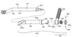
- a repositionable handle 500doubles as a component of the capture mechanism 447 in order to hold the two housing members 413 and 414 together.
- the capture mechanism 447slides over the front ends 448 of the housing members 413 and 414 , aligning each with one another and thus encapsulating the drive shaft 107 in order to protect the patient's skin from contacting the torque transmitting shaft 107 after being assembled.
- FIGS. 9A , 9 B and 9 Cmore clearly show how the housing members 413 and 414 are aligned and locked in place.
- the housing members 413 and 414are oriented with respect to each other when a locking sleeve 502 (having an internal diameter larger than the outside diameter of the housing members) slides over them, abutting against a bend 480 in the housing members.
- Thin, annular Teflon sleeves(not shown) are disposed between the housing members 413 and 414 and the locking sleeve 502 to facilitate disassembly.
- a forward mouth section 502 a of the locking sleeve 502cradles the bend 480 of the housing members 413 and 414 so as to prevent relative rotation of the locking sleeve and housing members.
- the capture mechanism 447has a locking device 450 which includes an annular sleeve 482 onto which the handle 500 is affixed.
- the annular sleeve 482includes a face 482 a having recesses 482 b (shown in FIG. 9C ) into which pins 484 , fixed to a shoulder 502 c of the locking sleeve 502 , are received in order to torsionally rigidly hold the handle 500 in any one of eight positions, according to the preference of the surgeon.
- a spring 486biases the annular sleeve 482 into engagement with the pins 484 via, on the one hand, applying spring pressure against an internal shoulder 482 c (shown in FIG. 9C ) in the annular sleeve 482 and, on the other hand, reacting against a locking ring 455 .
- the locking ring 455includes pins 490 which are affixed thereto and which enter into bayonet slots 492 in the locking sleeve 502 in order to hold the locking device 450 on the end of the locking sleeve and thus the capture mechanism 447 together.
- the housing members 413 and 414are held together via the pins 490 which engage the bayonet slots 492 a in each of the housing members 413 and 414 (best shown in FIG. 10 in which the annular sleeve 482 , the spring 486 and the locking sleeve 502 are removed for clarity).
- the pins 490 of the locking ring 455 and a catch 260interact with one another to retain the housing members 413 and 414 in a closed fashion while concurrently biasing the spring 486 so as to engage the annular sleeve 482 a (and thus the handle 500 ) with the pins 484 .
- annular sleeve 482sufficient play in the axial movement of the annular sleeve 482 is permitted to enable the surgeon to selectively disengage the sleeve from the pins 484 so as to reposition the handle about the locking sleeve 502 in any one of the eight angular positions of the handle 500 , while avoiding disassembly of the spindle 315 .
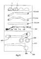
- these different types of housing members 213 - 214 , 313 - 314 , and 413 - 414can be offered as a kit 600 having a selection of different sized reamer housings 113 together with an impactor 602 , acetabular implants (not shown), femoral hip prostheses 604 , and acetabular cup prostheses ( 606 ), the selection of different reamer housing configurations allowing the surgeon to select between a bent, offset configuration or a straight configuration of the reamer spindle 115 , 215 , and 315 depending on the surgeons approach, which may vary during the same operation or between different patients.
Landscapes
- Health & Medical Sciences (AREA)
- Surgery (AREA)
- Life Sciences & Earth Sciences (AREA)
- Biomedical Technology (AREA)
- Medical Informatics (AREA)
- Veterinary Medicine (AREA)
- Public Health (AREA)
- Engineering & Computer Science (AREA)
- General Health & Medical Sciences (AREA)
- Heart & Thoracic Surgery (AREA)
- Nuclear Medicine, Radiotherapy & Molecular Imaging (AREA)
- Molecular Biology (AREA)
- Animal Behavior & Ethology (AREA)
- Dentistry (AREA)
- Oral & Maxillofacial Surgery (AREA)
- Orthopedic Medicine & Surgery (AREA)
- Surgical Instruments (AREA)
- Prostheses (AREA)
Abstract
Description
Claims (17)
Priority Applications (1)
| Application Number | Priority Date | Filing Date | Title |
|---|---|---|---|
| US11/935,198US7780669B2 (en) | 2002-04-30 | 2007-11-05 | Reamer spindle for minimally invasive joint surgery |
Applications Claiming Priority (6)
| Application Number | Priority Date | Filing Date | Title |
|---|---|---|---|
| US37647902P | 2002-04-30 | 2002-04-30 | |
| US38418602P | 2002-05-30 | 2002-05-30 | |
| US45959403P | 2003-04-02 | 2003-04-02 | |
| PCT/IB2003/001725WO2003092513A1 (en) | 2002-04-30 | 2003-04-28 | Reamer spindle for minimally invasive joint surgery |
| US11/123,932US7637909B2 (en) | 2002-04-30 | 2005-05-05 | Reamer spindle for minimally invasive joint surgery |
| US11/935,198US7780669B2 (en) | 2002-04-30 | 2007-11-05 | Reamer spindle for minimally invasive joint surgery |
Related Parent Applications (1)
| Application Number | Title | Priority Date | Filing Date |
|---|---|---|---|
| US11/123,932ContinuationUS7637909B2 (en) | 2002-04-30 | 2005-05-05 | Reamer spindle for minimally invasive joint surgery |
Publications (2)
| Publication Number | Publication Date |
|---|---|
| US20080065081A1 US20080065081A1 (en) | 2008-03-13 |
| US7780669B2true US7780669B2 (en) | 2010-08-24 |
Family
ID=29407787
Family Applications (3)
| Application Number | Title | Priority Date | Filing Date |
|---|---|---|---|
| US10/510,384Active2026-09-17US7785329B2 (en) | 2002-04-30 | 2003-04-28 | Reamer spindle for minimally invasive joint surgery |
| US11/123,932Expired - LifetimeUS7637909B2 (en) | 2002-04-30 | 2005-05-05 | Reamer spindle for minimally invasive joint surgery |
| US11/935,198Expired - LifetimeUS7780669B2 (en) | 2002-04-30 | 2007-11-05 | Reamer spindle for minimally invasive joint surgery |
Family Applications Before (2)
| Application Number | Title | Priority Date | Filing Date |
|---|---|---|---|
| US10/510,384Active2026-09-17US7785329B2 (en) | 2002-04-30 | 2003-04-28 | Reamer spindle for minimally invasive joint surgery |
| US11/123,932Expired - LifetimeUS7637909B2 (en) | 2002-04-30 | 2005-05-05 | Reamer spindle for minimally invasive joint surgery |
Country Status (8)
| Country | Link |
|---|---|
| US (3) | US7785329B2 (en) |
| EP (1) | EP1499248B1 (en) |
| JP (1) | JP4358102B2 (en) |
| KR (1) | KR100965538B1 (en) |
| CN (1) | CN1309349C (en) |
| AU (1) | AU2003219465A1 (en) |
| DE (1) | DE60331643D1 (en) |
| WO (1) | WO2003092513A1 (en) |
Cited By (21)
| Publication number | Priority date | Publication date | Assignee | Title |
|---|---|---|---|---|
| US8475460B1 (en) | 2010-02-23 | 2013-07-02 | Greatbatch Medical S.A. | Angled reamer spindle for minimally invasive hip replacement surgery |
| US8834471B2 (en) | 2010-02-23 | 2014-09-16 | Greatbatch Medical S.A. | Angled reamer spindle for minimally invasive hip replacement surgery |
| WO2015106136A1 (en)* | 2014-01-10 | 2015-07-16 | Catalyst Orthopaedics Llc | Glenoid arthroplasty and offset reamers |
| USD759819S1 (en) | 2013-03-11 | 2016-06-21 | Catalyst Orthopaedics Llc | Glenoid implant |
| USD780548S1 (en) | 2015-07-22 | 2017-03-07 | Ac (Macao Commercial Offshore) Limited | Power tool |
| US9610084B2 (en) | 2012-09-12 | 2017-04-04 | Peter Michael Sutherland Walker | Method and apparatus for hip replacements |
| US9814588B2 (en) | 2015-08-10 | 2017-11-14 | Catalyst Orthoscience Inc. | Glenoid arthroplasty with multi-directional fixation |
| USD806493S1 (en) | 2015-07-22 | 2018-01-02 | Tti (Macao Commercial Offshore) Limited | Tool adapter |
| US10028838B2 (en) | 2014-06-30 | 2018-07-24 | Tornier, Inc. | Augmented glenoid components and devices for implanting the same |
| US10314596B2 (en) | 2010-11-08 | 2019-06-11 | Tornier Sas | Orthopedic reamer for bone preparation, particularly glenoid preparation |
| US10687852B2 (en) | 2015-09-14 | 2020-06-23 | Symmetry Medical Manufacturing, Inc. | Separable instrument driver handle |
| US10973646B2 (en) | 2013-03-11 | 2021-04-13 | Catalyst Orthoscience Inc. | Stabilized drill guide |
| US11007064B2 (en) | 2015-08-10 | 2021-05-18 | Catalyst Orthoscience Inc. | Arthroplasty prostheses with multi-axis fixation |
| US11007063B2 (en) | 2013-03-11 | 2021-05-18 | Catalyst Orthoscience Inc. | Offset reamers |
| US11076869B2 (en)* | 2014-05-22 | 2021-08-03 | Symmetry Medical Manufacturing, Inc. | Offset orthopaedic reamer handle |
| US11129724B2 (en) | 2016-07-28 | 2021-09-28 | Howmedica Osteonics Corp. | Stemless prosthesis anchor component |
| US11234826B2 (en) | 2014-06-30 | 2022-02-01 | Howmedica Osteonics Corp. | Augmented glenoid components and devices for implanting the same |
| US11285009B2 (en) | 2019-07-12 | 2022-03-29 | Howmedica Osteonics Corp. | Augmented glenoid design |
| US11426285B2 (en) | 2019-09-05 | 2022-08-30 | Howmedica Osteonics Corp. | Truss glenoid augment |
| US11752000B2 (en) | 2020-03-03 | 2023-09-12 | Howmedica Osteonics Corp. | Glenoid implant with additively manufactured fixation posts |
| US11925362B2 (en) | 2021-12-10 | 2024-03-12 | Depuy Ireland Unlimited Company | Augment reamer and related methods |
Families Citing this family (79)
| Publication number | Priority date | Publication date | Assignee | Title |
|---|---|---|---|---|
| EP2308391B1 (en) | 2001-06-14 | 2016-08-31 | Endoevolution, Llc | Apparatus for surgical suturing with thread management |
| JP4384498B2 (en) | 2002-02-08 | 2009-12-16 | チャナ,ガーシャラン,シン | Improved surgical device and method of use |
| WO2003092513A1 (en) | 2002-04-30 | 2003-11-13 | Precimed S.A. | Reamer spindle for minimally invasive joint surgery |
| US7326215B2 (en)* | 2002-10-30 | 2008-02-05 | Symmetry Medical, Inc. | Curved surgical tool driver |
| WO2004071310A1 (en) | 2003-02-10 | 2004-08-26 | Smith & Nephew, Inc. | Acetabular reamer |
| US7749227B2 (en) | 2003-04-28 | 2010-07-06 | Greatbatch Medical S.A. | Precision assembleable surgical tool handle with limited-play interconnect mechanism |
| US8998919B2 (en) | 2003-06-25 | 2015-04-07 | DePuy Synthes Products, LLC | Assembly tool for modular implants, kit and associated method |
| US7582092B2 (en) | 2003-06-25 | 2009-09-01 | Depuy Products, Inc. | Assembly tool for modular implants and associated method |
| US7297166B2 (en) | 2003-06-25 | 2007-11-20 | Depuy Products, Inc. | Assembly tool for modular implants and associated method |
| US8657824B2 (en) | 2003-11-18 | 2014-02-25 | Smith & Nephew, Inc. | Universal double offset surgical instrument |
| DE602004023422D1 (en) | 2003-11-18 | 2009-11-12 | Smith & Nephew Inc | OPERATIVE TECHNIQUE AND INSTRUMENTS FOR MINIMAL INCISION HIP ARTHOPLASTY SURGERY |
| US7785328B2 (en)* | 2003-12-30 | 2010-08-31 | Depuy Products, Inc. | Minimally invasive bone miller apparatus |
| US8123764B2 (en) | 2004-09-20 | 2012-02-28 | Endoevolution, Llc | Apparatus and method for minimally invasive suturing |
| US9775600B2 (en) | 2010-10-01 | 2017-10-03 | Endoevolution, Llc | Devices and methods for minimally invasive suturing |
| US7976555B2 (en) | 2008-07-17 | 2011-07-12 | Endoevolution, Llc | Apparatus and method for minimally invasive suturing |
| GB0503529D0 (en)* | 2005-02-21 | 2005-03-30 | Smith & Nephew Inc | Medical device |
| WO2006100658A2 (en)* | 2005-03-22 | 2006-09-28 | Atropos Limited | A surgical instrument |
| US7608076B2 (en)* | 2005-04-29 | 2009-10-27 | Greatbatch Medical S.A. | Minimally invasive collapsible surgical reamer |
| US20070072466A1 (en) | 2005-09-27 | 2007-03-29 | Manabu Miyamoto | Instrument for endoscope |
| US8398639B2 (en)* | 2005-09-29 | 2013-03-19 | Symmetry Medical Manufacturing, Inc. | Minimally invasive surgical driver |
| US7993348B2 (en)* | 2005-12-20 | 2011-08-09 | Howmedica Osteonics Corp. | Curved acetabular positioner, impactor and reamer handle |
| CA2854625C (en) | 2006-01-27 | 2017-01-24 | Suturtek Incorporated | Apparatus and method for tissue closure |
| US7935125B2 (en)* | 2006-03-06 | 2011-05-03 | Howmedica Osteonics Corp. | Compound offset handle |
| US20070276396A1 (en)* | 2006-05-10 | 2007-11-29 | Howmedica Osteonics Corp. | Modular acetabular reamer |
| US8597298B2 (en) | 2006-09-29 | 2013-12-03 | DePuy Synthes Products, LLC | Proximal reamer |
| EP1905362A1 (en)* | 2006-09-29 | 2008-04-02 | Precimed S.A. | Precision assembleable surgical tool handle with limited-play interconnect mechanism |
| US8425526B2 (en)* | 2006-10-17 | 2013-04-23 | Smith & Nephew, Inc. | Adjustable impactor |
| FR2909855A1 (en)* | 2006-12-13 | 2008-06-20 | Bioprofile Soc Par Actions Sim | MILLING FOR SURGICAL USE |
| US8052689B2 (en) | 2006-12-30 | 2011-11-08 | Greatbatch Medical S.A. | Cut-off acetabular reamer |
| FR2911773B1 (en) | 2007-01-30 | 2009-03-27 | Tornier Sas | METHOD AND ASSEMBLY OF SURGICAL INSTRUMENTATION FOR POSITIONING A TOTAL REVERSE SHOULDER PROSTHESIS, AND CORRESPONDING PROSTHESIS |
| US20090287309A1 (en) | 2007-01-30 | 2009-11-19 | Tornier Sas | Intra-articular joint replacement |
| US8556912B2 (en) | 2007-10-30 | 2013-10-15 | DePuy Synthes Products, LLC | Taper disengagement tool |
| US8518050B2 (en) | 2007-10-31 | 2013-08-27 | DePuy Synthes Products, LLC | Modular taper assembly device |
| US8167882B2 (en) | 2008-09-30 | 2012-05-01 | Depuy Products, Inc. | Minimally invasive bone miller apparatus |
| JP5324277B2 (en)* | 2009-03-25 | 2013-10-23 | 京セラメディカル株式会社 | Surgical instruments for joint replacement |
| US8435243B2 (en) | 2010-02-12 | 2013-05-07 | Greatbatch Ltd. | Disposable reamer |
| US9408652B2 (en) | 2010-04-27 | 2016-08-09 | Tornier Sas | Intra-articular joint replacement and method |
| US8533921B2 (en) | 2010-06-15 | 2013-09-17 | DePuy Synthes Products, LLC | Spiral assembly tool |
| US9095452B2 (en) | 2010-09-01 | 2015-08-04 | DePuy Synthes Products, Inc. | Disassembly tool |
| US9078672B1 (en)* | 2010-11-05 | 2015-07-14 | Greatbatch Medical S.A. | Carbon reamer handle |
| KR101259690B1 (en)* | 2011-03-31 | 2013-05-02 | 정창욱 | Instrument for Minimally Invasive Surgery Having Shaft Including Inner Torque Transmission Member |
| ES2635496T3 (en) | 2011-04-06 | 2017-10-04 | Depuy Synthes Products Llc | Modular Orthopedic Hip Prosthesis |
| WO2013165942A1 (en) | 2012-05-01 | 2013-11-07 | Brigham And Women's Hospital, Inc. | Suturing device for laparoscopic procedures |
| TW201412281A (en)* | 2012-09-18 | 2014-04-01 | United Orthopedic Corp | Acetabular cup implanting device |
| FR3007635B1 (en)* | 2013-06-26 | 2016-02-19 | Xnov Ip | HANDLE HOLDER WITH HANDLE |
| US9345585B2 (en) | 2013-10-08 | 2016-05-24 | Howmedica Osteonics Corp. | Acetabular cup insertion instruments |
| US10568649B2 (en) | 2014-05-06 | 2020-02-25 | Howmedica Osteonics Corp. | Acetabular reamer |
| US20160135862A1 (en)* | 2014-11-17 | 2016-05-19 | Spinal Elements, Inc. | Curved surgical tools |
| WO2017029546A2 (en)* | 2015-08-18 | 2017-02-23 | Incipio Devices Sa | Offset reamer driver |
| US10335169B2 (en)* | 2015-09-14 | 2019-07-02 | Symmetry Medical Manufacturing, Inc. | Angled orthopaedic driver |
| WO2018033788A1 (en)* | 2016-08-18 | 2018-02-22 | Incipio Devices Sa | Offset reamer driver |
| EP3500189B1 (en)* | 2016-08-18 | 2021-07-14 | Incipio Devices SA | Offset reamer driver |
| US9737314B1 (en) | 2016-11-14 | 2017-08-22 | Greatbatch Ltd. | Broach handle with bias attachment |
| IT201600116509A1 (en)* | 2016-11-17 | 2018-05-17 | Medacta Int Sa | GUIDE FOR INTRAMIDOLLAR REAMER |
| WO2018119459A1 (en) | 2016-12-23 | 2018-06-28 | Brigham And Women's Hospital, Inc. | Systems and methods for suturing tissue |
| US20180242967A1 (en) | 2017-02-26 | 2018-08-30 | Endoevolution, Llc | Apparatus and method for minimally invasive suturing |
| US10881530B2 (en)* | 2017-04-28 | 2021-01-05 | Warsaw Orthopedic, Inc. | Surgical instrument and method |
| US10292698B2 (en) | 2017-07-27 | 2019-05-21 | Endoevolution, Llc | Apparatus and method for minimally invasive suturing |
| GB201802789D0 (en) | 2018-02-21 | 2018-04-04 | Depuy Ireland Ultd Co | Acetabular reamer handle and method of reaming an acetabulum |
| US11806250B2 (en) | 2018-02-22 | 2023-11-07 | Warsaw Orthopedic, Inc. | Expandable spinal implant system and method of using same |
| KR102134342B1 (en) | 2018-07-18 | 2020-08-26 | 재단법인대구경북과학기술원 | Method for estimating deformation degree of endoscope by tendon-based actuating system and system using the same |
| KR102580180B1 (en)* | 2018-11-14 | 2023-09-20 | 콘메드 코포레이션 | Method of securing the shaft of a surgical instrument to the instrument housing |
| EP4069105A2 (en)* | 2019-12-02 | 2022-10-12 | DePuy Ireland Unlimited Company | Adjustable reamer driver and impactor, and methods of preparing said driver and impactor |
| US11642139B2 (en)* | 2020-03-05 | 2023-05-09 | Origin Medical, Llc. | Acetabular and glenoid reamer systems and methods using the same |
| US12121453B2 (en) | 2020-11-05 | 2024-10-22 | Warsaw Orthopedic, Inc. | Dual wedge expandable implant with eyelets, system, and method of use |
| US12239544B2 (en) | 2020-11-05 | 2025-03-04 | Warsaw Orthopedic, Inc. | Rhomboid shaped implants |
| US11963881B2 (en) | 2020-11-05 | 2024-04-23 | Warsaw Orthopedic, Inc. | Expandable inter-body device, system, and method |
| US11517443B2 (en) | 2020-11-05 | 2022-12-06 | Warsaw Orthopedic, Inc. | Dual wedge expandable implant, system and method of use |
| US12318308B2 (en) | 2020-11-05 | 2025-06-03 | Warsaw Orthopedic, Inc. | Dual expandable inter-body device |
| US11517363B2 (en) | 2020-11-05 | 2022-12-06 | Warsaw Orthopedic, Inc. | Screw driver and complimentary screws |
| US11833059B2 (en) | 2020-11-05 | 2023-12-05 | Warsaw Orthopedic, Inc. | Expandable inter-body device, expandable plate system, and associated methods |
| US12171439B2 (en) | 2020-11-05 | 2024-12-24 | Warsaw Orthopedic, Inc. | Protected drill |
| US11638653B2 (en)* | 2020-11-05 | 2023-05-02 | Warsaw Orthopedic, Inc. | Surgery instruments with a movable handle |
| CN113081154A (en)* | 2021-04-02 | 2021-07-09 | 上海电气集团股份有限公司 | Acetabular bone file curved rod mechanism |
| US12402877B2 (en) | 2021-06-07 | 2025-09-02 | Intuitive Surgical Operations, Inc. | Needle loader devices and related systems and methods |
| WO2022271280A1 (en) | 2021-06-24 | 2022-12-29 | Warsaw Orthopedic, Inc. | Expandable interbody implant and corresponding surgical tool |
| US12295865B2 (en) | 2021-06-24 | 2025-05-13 | Warsaw Orthopedic, Inc. | Expandable interbody implant and corresponding inserter |
| US11612499B2 (en) | 2021-06-24 | 2023-03-28 | Warsaw Orthopedic, Inc. | Expandable interbody implant |
| CN115227463B (en)* | 2022-07-22 | 2023-04-07 | 北京长木谷医疗科技有限公司 | Surgical instrument's rasping device, surgical instrument and surgical robot |
Citations (23)
| Publication number | Priority date | Publication date | Assignee | Title |
|---|---|---|---|---|
| US300557A (en) | 1884-06-17 | foesteb | ||
| US4305394A (en)* | 1980-12-22 | 1981-12-15 | Bertuch Jr Charles J | Acetabular cup positioning instrument |
| US4528980A (en) | 1983-10-19 | 1985-07-16 | Howmedica, Inc. | Acetabulum sizer and drill guide |
| US5171312A (en) | 1990-05-03 | 1992-12-15 | Othy, Inc. | Tool driver |
| US5176711A (en) | 1991-03-06 | 1993-01-05 | Grimes James B | Acetabular revision system |
| JPH05123334A (en) | 1991-11-07 | 1993-05-21 | Aisin Seiki Co Ltd | Surgical apparatus for substitution with artificial joint |
| US5474560A (en) | 1994-09-26 | 1995-12-12 | Zimmer, Inc. | Prosthetic acetabular cup inserter |
| US5925077A (en)* | 1997-04-02 | 1999-07-20 | Biomet, Inc. | Apparatus and method for plugging holes in an acetabular shell component |
| US5951561A (en)* | 1998-06-30 | 1999-09-14 | Smith & Nephew, Inc. | Minimally invasive intramedullary nail insertion instruments and method |
| US6174313B1 (en) | 1990-06-28 | 2001-01-16 | Peter M. Bonutti | Apparatus and method for tissue removal |
| US6312438B1 (en) | 2000-02-01 | 2001-11-06 | Medtronic Xomed, Inc. | Rotary bur instruments having bur tips with aspiration passages |
| US20020004660A1 (en) | 2000-02-24 | 2002-01-10 | Stryker Instruments | Bioabsorbable plates. fasteners, tools and method of using same |
| US6436107B1 (en)* | 1996-02-20 | 2002-08-20 | Computer Motion, Inc. | Method and apparatus for performing minimally invasive surgical procedures |
| US6451058B2 (en) | 1997-03-14 | 2002-09-17 | Finsbury (Development) Limited | Prosthetic implant and surgical tool |
| US6475221B1 (en) | 1998-03-18 | 2002-11-05 | Patrick M. White | Connector for domed cutting tool |
| US20030050645A1 (en) | 2002-10-30 | 2003-03-13 | Parker Brad A. | Acetabular cup impactor |
| US20030130741A1 (en) | 2002-01-07 | 2003-07-10 | Mcminn Derek James Wallace | Hip prosthesis |
| WO2003065906A2 (en) | 2002-02-08 | 2003-08-14 | Gursharan Singh Chana | Device for holding and rotating an acetabulum reamer |
| WO2003092513A1 (en) | 2002-04-30 | 2003-11-13 | Precimed S.A. | Reamer spindle for minimally invasive joint surgery |
| US6676706B1 (en) | 2000-04-26 | 2004-01-13 | Zimmer Technology, Inc. | Method and apparatus for performing a minimally invasive total hip arthroplasty |
| US20040087958A1 (en) | 2002-10-30 | 2004-05-06 | Myers Reese K. | Curved surgical tool driver |
| US6854742B2 (en)* | 1999-07-09 | 2005-02-15 | Symmetry Medical, Inc. | Tool driver |
| US7008430B2 (en) | 2003-01-31 | 2006-03-07 | Howmedica Osteonics Corp. | Adjustable reamer with tip tracker linkage |
Family Cites Families (20)
| Publication number | Priority date | Publication date | Assignee | Title |
|---|---|---|---|---|
| DE261260C (en)* | 1900-01-01 | |||
| US2093682A (en)* | 1935-11-13 | 1937-09-21 | Dudley Res Corp | Dental tool holder |
| DE2547969A1 (en)* | 1975-10-27 | 1977-04-28 | Hanfried Dr Med Weigand | Cutting tool for artificial hip joint socket - with motor driven shaft mounted in support with handle |
| EP0261260A1 (en)* | 1986-09-23 | 1988-03-30 | Heinz-Jürgen List | Surgical bone drill |
| DE3828478C2 (en)* | 1987-10-30 | 1994-05-05 | Olympus Optical Co | Surgical resection device |
| US5529580A (en)* | 1987-10-30 | 1996-06-25 | Olympus Optical Co., Ltd. | Surgical resecting tool |
| US5061270A (en)* | 1991-03-18 | 1991-10-29 | Aboczky Robert I | System for orienting, inserting and impacting an acetabular cup prosthesis |
| US5814049A (en)* | 1995-10-27 | 1998-09-29 | Kinamed, Inc. | Process for applying suction to bone drilling and reaming operations |
| US5697158A (en)* | 1995-12-21 | 1997-12-16 | Minnesota Mining And Manufacturing Company | Orthopedic surgical device having a rotatable portion and lock |
| AUPN741996A0 (en)* | 1996-01-04 | 1996-01-25 | Interfix Limited | A driver |
| US5817096A (en)* | 1996-11-25 | 1998-10-06 | Othy, Inc. | Tool driver |
| US6432070B1 (en)* | 1999-05-11 | 2002-08-13 | Exogen, Inc. | Method and apparatus for ultrasonic treatment of reflex sympathetic dystrophy |
| US6250858B1 (en)* | 1998-03-27 | 2001-06-26 | Othy, Inc. | Tool driver and tools therefor |
| EP0965308B1 (en)* | 1998-06-17 | 2007-08-01 | Precimed S.A. | Surgical reamer |
| US6565575B2 (en)* | 2001-02-16 | 2003-05-20 | Randall J. Lewis | Method and apparatus for removing an acetabular cup |
| DE10112527C1 (en)* | 2001-03-15 | 2002-10-10 | Mathys Medizinaltechnik Ag Bet | Setting tool for inserting an expansion shell |
| EP1402148A1 (en) | 2001-06-29 | 2004-03-31 | Smit Land & Marine Engineering Limited | Method of laying an underwater flowline |
| WO2003057049A1 (en)* | 2002-01-11 | 2003-07-17 | Waldemar Link (Gmbh & Co.) | Surgical instrument for routing out the hip socket |
| US6949101B2 (en)* | 2002-03-29 | 2005-09-27 | Depuy Orthopaedics, Inc. | Medical instrument for milling a curved path in bone and procedure |
| US7335207B1 (en) | 2003-11-26 | 2008-02-26 | Biomet Manufacturing Corp. | Minimally invasive cup impactor |
- 2003
- 2003-04-28WOPCT/IB2003/001725patent/WO2003092513A1/enactiveApplication Filing
- 2003-04-28CNCNB03809651XApatent/CN1309349C/ennot_activeExpired - Lifetime
- 2003-04-28DEDE60331643Tpatent/DE60331643D1/ennot_activeExpired - Lifetime
- 2003-04-28USUS10/510,384patent/US7785329B2/enactiveActive
- 2003-04-28EPEP03715277Apatent/EP1499248B1/ennot_activeExpired - Lifetime
- 2003-04-28KRKR1020047017313Apatent/KR100965538B1/ennot_activeExpired - Lifetime
- 2003-04-28JPJP2004500703Apatent/JP4358102B2/ennot_activeExpired - Lifetime
- 2003-04-28AUAU2003219465Apatent/AU2003219465A1/ennot_activeAbandoned
- 2005
- 2005-05-05USUS11/123,932patent/US7637909B2/ennot_activeExpired - Lifetime
- 2007
- 2007-11-05USUS11/935,198patent/US7780669B2/ennot_activeExpired - Lifetime
Patent Citations (24)
| Publication number | Priority date | Publication date | Assignee | Title |
|---|---|---|---|---|
| US300557A (en) | 1884-06-17 | foesteb | ||
| US4305394A (en)* | 1980-12-22 | 1981-12-15 | Bertuch Jr Charles J | Acetabular cup positioning instrument |
| US4528980A (en) | 1983-10-19 | 1985-07-16 | Howmedica, Inc. | Acetabulum sizer and drill guide |
| US5171312A (en) | 1990-05-03 | 1992-12-15 | Othy, Inc. | Tool driver |
| US6174313B1 (en) | 1990-06-28 | 2001-01-16 | Peter M. Bonutti | Apparatus and method for tissue removal |
| US5176711A (en) | 1991-03-06 | 1993-01-05 | Grimes James B | Acetabular revision system |
| JPH05123334A (en) | 1991-11-07 | 1993-05-21 | Aisin Seiki Co Ltd | Surgical apparatus for substitution with artificial joint |
| US5474560A (en) | 1994-09-26 | 1995-12-12 | Zimmer, Inc. | Prosthetic acetabular cup inserter |
| US6436107B1 (en)* | 1996-02-20 | 2002-08-20 | Computer Motion, Inc. | Method and apparatus for performing minimally invasive surgical procedures |
| US6451058B2 (en) | 1997-03-14 | 2002-09-17 | Finsbury (Development) Limited | Prosthetic implant and surgical tool |
| US5925077A (en)* | 1997-04-02 | 1999-07-20 | Biomet, Inc. | Apparatus and method for plugging holes in an acetabular shell component |
| US6475221B1 (en) | 1998-03-18 | 2002-11-05 | Patrick M. White | Connector for domed cutting tool |
| US5951561A (en)* | 1998-06-30 | 1999-09-14 | Smith & Nephew, Inc. | Minimally invasive intramedullary nail insertion instruments and method |
| US6854742B2 (en)* | 1999-07-09 | 2005-02-15 | Symmetry Medical, Inc. | Tool driver |
| US6312438B1 (en) | 2000-02-01 | 2001-11-06 | Medtronic Xomed, Inc. | Rotary bur instruments having bur tips with aspiration passages |
| US20020004660A1 (en) | 2000-02-24 | 2002-01-10 | Stryker Instruments | Bioabsorbable plates. fasteners, tools and method of using same |
| US6676706B1 (en) | 2000-04-26 | 2004-01-13 | Zimmer Technology, Inc. | Method and apparatus for performing a minimally invasive total hip arthroplasty |
| US20030130741A1 (en) | 2002-01-07 | 2003-07-10 | Mcminn Derek James Wallace | Hip prosthesis |
| WO2003065906A2 (en) | 2002-02-08 | 2003-08-14 | Gursharan Singh Chana | Device for holding and rotating an acetabulum reamer |
| WO2003065906A3 (en) | 2002-02-08 | 2003-11-27 | Gursharan Singh Chana | Device for holding and rotating an acetabulum reamer |
| WO2003092513A1 (en) | 2002-04-30 | 2003-11-13 | Precimed S.A. | Reamer spindle for minimally invasive joint surgery |
| US20040087958A1 (en) | 2002-10-30 | 2004-05-06 | Myers Reese K. | Curved surgical tool driver |
| US20030050645A1 (en) | 2002-10-30 | 2003-03-13 | Parker Brad A. | Acetabular cup impactor |
| US7008430B2 (en) | 2003-01-31 | 2006-03-07 | Howmedica Osteonics Corp. | Adjustable reamer with tip tracker linkage |
Non-Patent Citations (5)
| Title |
|---|
| Office action dated Dec. 17, 2007 in U.S. Appl. No. 10/503,788. |
| Office action dated Jul. 9, 2008 in U.S. Appl. No. 10/503,788. |
| Office action dated Mar. 12, 2009 in U.S. Appl. No. 10/503,788. |
| Suggestion for interference filed in U.S. Appl. No. 11/122,092, on Feb. 24, 2006. |
| Suggestion for interference filed in U.S. Appl. No. 11/122,092, on Mar. 10, 2006. |
Cited By (30)
| Publication number | Priority date | Publication date | Assignee | Title |
|---|---|---|---|---|
| US8480674B1 (en) | 2010-02-23 | 2013-07-09 | Greatbatch Medical S.A. | Angled reamer spindle for minimally invasive hip replacement surgery |
| US8834471B2 (en) | 2010-02-23 | 2014-09-16 | Greatbatch Medical S.A. | Angled reamer spindle for minimally invasive hip replacement surgery |
| US8475460B1 (en) | 2010-02-23 | 2013-07-02 | Greatbatch Medical S.A. | Angled reamer spindle for minimally invasive hip replacement surgery |
| US11806023B2 (en) | 2010-11-08 | 2023-11-07 | Tornier Sas | Orthopedic reamer for bone preparation, particularly glenoid preparation |
| US10314596B2 (en) | 2010-11-08 | 2019-06-11 | Tornier Sas | Orthopedic reamer for bone preparation, particularly glenoid preparation |
| US11207078B2 (en) | 2010-11-08 | 2021-12-28 | Tornier Sas | Orthopedic reamer for bone preparation, particularly glenoid preparation |
| US12193685B2 (en) | 2010-11-08 | 2025-01-14 | Tornier Sas | Orthopedic reamer for bone preparation, particularly glenoid preparation |
| US9610084B2 (en) | 2012-09-12 | 2017-04-04 | Peter Michael Sutherland Walker | Method and apparatus for hip replacements |
| USD759819S1 (en) | 2013-03-11 | 2016-06-21 | Catalyst Orthopaedics Llc | Glenoid implant |
| US9814471B2 (en) | 2013-03-11 | 2017-11-14 | Catalyst Orthoscience Inc. | Glenoid arthroplasty and offset reamers |
| US9775716B2 (en) | 2013-03-11 | 2017-10-03 | Catalyst Orthoscience Inc. | Glenoid arthroplasty |
| USD810940S1 (en) | 2013-03-11 | 2018-02-20 | Catalyst Orthoscience Inc. | Implant |
| US11007063B2 (en) | 2013-03-11 | 2021-05-18 | Catalyst Orthoscience Inc. | Offset reamers |
| US10973646B2 (en) | 2013-03-11 | 2021-04-13 | Catalyst Orthoscience Inc. | Stabilized drill guide |
| WO2015106136A1 (en)* | 2014-01-10 | 2015-07-16 | Catalyst Orthopaedics Llc | Glenoid arthroplasty and offset reamers |
| US11076869B2 (en)* | 2014-05-22 | 2021-08-03 | Symmetry Medical Manufacturing, Inc. | Offset orthopaedic reamer handle |
| US11234826B2 (en) | 2014-06-30 | 2022-02-01 | Howmedica Osteonics Corp. | Augmented glenoid components and devices for implanting the same |
| US10028838B2 (en) | 2014-06-30 | 2018-07-24 | Tornier, Inc. | Augmented glenoid components and devices for implanting the same |
| US12186197B2 (en) | 2014-06-30 | 2025-01-07 | Howmedica Osteonics Corp. | Augmented glenoid components and devices for implanting the same |
| USD806493S1 (en) | 2015-07-22 | 2018-01-02 | Tti (Macao Commercial Offshore) Limited | Tool adapter |
| USD780548S1 (en) | 2015-07-22 | 2017-03-07 | Ac (Macao Commercial Offshore) Limited | Power tool |
| US11007064B2 (en) | 2015-08-10 | 2021-05-18 | Catalyst Orthoscience Inc. | Arthroplasty prostheses with multi-axis fixation |
| US9814588B2 (en) | 2015-08-10 | 2017-11-14 | Catalyst Orthoscience Inc. | Glenoid arthroplasty with multi-directional fixation |
| US10687852B2 (en) | 2015-09-14 | 2020-06-23 | Symmetry Medical Manufacturing, Inc. | Separable instrument driver handle |
| US11129724B2 (en) | 2016-07-28 | 2021-09-28 | Howmedica Osteonics Corp. | Stemless prosthesis anchor component |
| US12109122B2 (en) | 2019-07-12 | 2024-10-08 | Howmedica Osteonics Corp. | Augmented glenoid design |
| US11285009B2 (en) | 2019-07-12 | 2022-03-29 | Howmedica Osteonics Corp. | Augmented glenoid design |
| US11426285B2 (en) | 2019-09-05 | 2022-08-30 | Howmedica Osteonics Corp. | Truss glenoid augment |
| US11752000B2 (en) | 2020-03-03 | 2023-09-12 | Howmedica Osteonics Corp. | Glenoid implant with additively manufactured fixation posts |
| US11925362B2 (en) | 2021-12-10 | 2024-03-12 | Depuy Ireland Unlimited Company | Augment reamer and related methods |
Also Published As
| Publication number | Publication date |
|---|---|
| US20050216022A1 (en) | 2005-09-29 |
| US7637909B2 (en) | 2009-12-29 |
| KR20040104649A (en) | 2004-12-10 |
| EP1499248A1 (en) | 2005-01-26 |
| AU2003219465A1 (en) | 2003-11-17 |
| CN1649546A (en) | 2005-08-03 |
| KR100965538B1 (en) | 2010-06-23 |
| US7785329B2 (en) | 2010-08-31 |
| CN1309349C (en) | 2007-04-11 |
| JP2005523764A (en) | 2005-08-11 |
| JP4358102B2 (en) | 2009-11-04 |
| WO2003092513A1 (en) | 2003-11-13 |
| EP1499248B1 (en) | 2010-03-10 |
| US20050240192A1 (en) | 2005-10-27 |
| US20080065081A1 (en) | 2008-03-13 |
| DE60331643D1 (en) | 2010-04-22 |
| US20090318922A9 (en) | 2009-12-24 |
Similar Documents
| Publication | Publication Date | Title |
|---|---|---|
| US7780669B2 (en) | Reamer spindle for minimally invasive joint surgery | |
| US7749227B2 (en) | Precision assembleable surgical tool handle with limited-play interconnect mechanism | |
| US7857816B2 (en) | Inserter for minimally invasive joint surgery having interchangeable thread | |
| US7976548B2 (en) | Surgical tool holder for facilitated sterilization | |
| US7503921B2 (en) | Variable angle orthopaedic reamer driver | |
| US9078672B1 (en) | Carbon reamer handle | |
| US8480674B1 (en) | Angled reamer spindle for minimally invasive hip replacement surgery | |
| US7473254B2 (en) | Pivoting bone reamer for minimally invasive joint surgery | |
| US8834471B2 (en) | Angled reamer spindle for minimally invasive hip replacement surgery | |
| JPH05277142A (en) | Modular trial tool with interlock mechanism | |
| JP2011139918A (en) | Apparatus and method for minimally invasive total joint replacement | |
| EP2626017B1 (en) | A reamer handle for reaming the pelvis (acetabulum) in minimal invasive orthopedic surgery | |
| US20220125547A1 (en) | Surgical instrument handle with implant sizing feature and method of using | |
| EP1905362A1 (en) | Precision assembleable surgical tool handle with limited-play interconnect mechanism | |
| AU2020206880A1 (en) | Surgical instrument handle with implant sizing feature | |
| EP4223237B1 (en) | Acetabular cup remover assembly | |
| JP2021514260A (en) | Acetabular reamer handle and how to ream the acetabulum |
Legal Events
| Date | Code | Title | Description |
|---|---|---|---|
| AS | Assignment | Owner name:GREATBATCH MEDICAL S.A., SWITZERLAND Free format text:CHANGE OF NAME;ASSIGNOR:PRECIMED S.A.;REEL/FRAME:023032/0198 Effective date:20090730 Owner name:GREATBATCH MEDICAL S.A.,SWITZERLAND Free format text:CHANGE OF NAME;ASSIGNOR:PRECIMED S.A.;REEL/FRAME:023032/0198 Effective date:20090730 | |
| STCF | Information on status: patent grant | Free format text:PATENTED CASE | |
| AS | Assignment | Owner name:GREATBATCH MEDICAL S.A., SWITZERLAND Free format text:ASSIGNMENT OF ASSIGNORS INTEREST;ASSIGNORS:LECHOT, ANDRE;DESARZENS, YVES;DAVIES, HUGH;AND OTHERS;SIGNING DATES FROM 20110617 TO 20110808;REEL/FRAME:026746/0972 | |
| FPAY | Fee payment | Year of fee payment:4 | |
| MAFP | Maintenance fee payment | Free format text:PAYMENT OF MAINTENANCE FEE, 8TH YEAR, LARGE ENTITY (ORIGINAL EVENT CODE: M1552) Year of fee payment:8 | |
| AS | Assignment | Owner name:ROYAL BANK OF CANADA, AS COLLATERAL AGENT, CANADA Free format text:SECURITY INTEREST;ASSIGNOR:BANDERA ACQUISITION, LLC;REEL/FRAME:046472/0545 Effective date:20180702 Owner name:ROYAL BANK OF CANADA, AS COLLATERAL AGENT, CANADA Free format text:SECURITY INTEREST;ASSIGNOR:BANDERA ACQUISITION, LLC;REEL/FRAME:046472/0475 Effective date:20180702 | |
| AS | Assignment | Owner name:BANDERA ACQUISITION, LLC, MASSACHUSETTS Free format text:ASSIGNMENT OF ASSIGNORS INTEREST;ASSIGNOR:GREATBATCH MEDICAL SA;REEL/FRAME:047154/0186 Effective date:20180702 | |
| AS | Assignment | Owner name:VIANT AS&O HOLDINGS, LLC, ARIZONA Free format text:CHANGE OF NAME;ASSIGNOR:BANDERA ACQUISITION, LLC;REEL/FRAME:047221/0275 Effective date:20180824 | |
| MAFP | Maintenance fee payment | Free format text:PAYMENT OF MAINTENANCE FEE, 12TH YEAR, LARGE ENTITY (ORIGINAL EVENT CODE: M1553); ENTITY STATUS OF PATENT OWNER: LARGE ENTITY Year of fee payment:12 | |
| AS | Assignment | Owner name:VIANT AS&O HOLDINGS, LLC, MASSACHUSETTS Free format text:RELEASE BY SECURED PARTY;ASSIGNOR:ROYAL BANK OF CANADA;REEL/FRAME:069276/0081 Effective date:20241029 | |
| AS | Assignment | Owner name:UBS AG, STAMFORD BRANCH, CONNECTICUT Free format text:SECURITY INTEREST;ASSIGNOR:VIANT AS&O HOLDINGS, LLC;REEL/FRAME:069287/0709 Effective date:20241029 Owner name:VIANT AS&O HOLDINGS, LLC, MASSACHUSETTS Free format text:RELEASE BY SECURED PARTY;ASSIGNOR:ROYAL BANK OF CANADA;REEL/FRAME:069286/0564 Effective date:20241029 | |
| AS | Assignment | Owner name:HPS INVESTMENT PARTNERS, LLC, AS COLLATERAL AGENT, NEW YORK Free format text:SECOND LIEN PATENT SECURITY AGREEMENT;ASSIGNOR:VIANT AS&O HOLDINGS, LLC (F/K/A BANDERA ACQUISITION, LLC);REEL/FRAME:069288/0915 Effective date:20241029 |