US7780666B1 - Fixed and variable locking fixation assembly - Google Patents
Fixed and variable locking fixation assemblyDownload PDFInfo
- Publication number
- US7780666B1 US7780666B1US11/142,702US14270205AUS7780666B1US 7780666 B1US7780666 B1US 7780666B1US 14270205 AUS14270205 AUS 14270205AUS 7780666 B1US7780666 B1US 7780666B1
- Authority
- US
- United States
- Prior art keywords
- diameter
- screw
- head
- locking fastener
- groove
- Prior art date
- Legal status (The legal status is an assumption and is not a legal conclusion. Google has not performed a legal analysis and makes no representation as to the accuracy of the status listed.)
- Expired - Lifetime, expires
Links
Images


Classifications
- A—HUMAN NECESSITIES
- A61—MEDICAL OR VETERINARY SCIENCE; HYGIENE
- A61B—DIAGNOSIS; SURGERY; IDENTIFICATION
- A61B17/00—Surgical instruments, devices or methods
- A61B17/56—Surgical instruments or methods for treatment of bones or joints; Devices specially adapted therefor
- A61B17/58—Surgical instruments or methods for treatment of bones or joints; Devices specially adapted therefor for osteosynthesis, e.g. bone plates, screws or setting implements
- A61B17/68—Internal fixation devices, including fasteners and spinal fixators, even if a part thereof projects from the skin
- A61B17/80—Cortical plates, i.e. bone plates; Instruments for holding or positioning cortical plates, or for compressing bones attached to cortical plates
- A61B17/8033—Cortical plates, i.e. bone plates; Instruments for holding or positioning cortical plates, or for compressing bones attached to cortical plates having indirect contact with screw heads, or having contact with screw heads maintained with the aid of additional components, e.g. nuts, wedges or head covers
- A61B17/8047—Cortical plates, i.e. bone plates; Instruments for holding or positioning cortical plates, or for compressing bones attached to cortical plates having indirect contact with screw heads, or having contact with screw heads maintained with the aid of additional components, e.g. nuts, wedges or head covers wherein the additional element surrounds the screw head in the plate hole
- A—HUMAN NECESSITIES
- A61—MEDICAL OR VETERINARY SCIENCE; HYGIENE
- A61B—DIAGNOSIS; SURGERY; IDENTIFICATION
- A61B17/00—Surgical instruments, devices or methods
- A61B17/56—Surgical instruments or methods for treatment of bones or joints; Devices specially adapted therefor
- A61B17/58—Surgical instruments or methods for treatment of bones or joints; Devices specially adapted therefor for osteosynthesis, e.g. bone plates, screws or setting implements
- A61B17/68—Internal fixation devices, including fasteners and spinal fixators, even if a part thereof projects from the skin
- A61B17/70—Spinal positioners or stabilisers, e.g. stabilisers comprising fluid filler in an implant
- A61B17/7059—Cortical plates
Definitions
- the present inventionrelates generally to locking fixation assemblies. More specifically, the present invention relates to a fixed and variable locking screw that can be used in bone fixation assemblies.
- fixation platesfor the treatment of spinal disorders including spinal anomalies, spinal injuries, disc problems, and bone problems. Indeed, within the past several years, the use of fixation plates for the treatment of spinal disorders or for fusion of vertebrae has grown considerably, and spinal plates have found increased use and desirability in the cervical spine as well.
- the upper cervical spinecan be approached either anteriorly or posteriorly, depending upon the spinal disorder to be treated.
- This textdiscusses the fact that severe complications associated with procedures involving the upper cervical spine can be catastrophic, including injuries to the brain stem, spinal cord, or vertebral arteries, not to mention damage to the esophagus.
- These complications for upper cervical spine proceduresare in addition to the normal complications associated with exposure and fusion of the cervical spine, implantation of a spinal fixation plate, and general disturbance of the spine.
- an orthopedic plateis attached to an adjacent bone by one or more fasteners, typically screws.
- fastenerstypically screws.
- any device implanted into the human bodycan cause some type of tissue reaction to the implanted foreign material.
- One area where the anatomic limit is particularly notableis in the upper cervical region. For these reasons it is sometimes desirable to use the smallest feasible fasteners for fixating bone segments.
- orthopedic implantsIn anterior cervical applications in particular, orthopedic implants must be of very small size given the anatomical constraints related to work in this region. As a result, any implant to be placed in this region must be not only of diminutive length and width, but must also be of very small height in order to not protrude into the adjacent tissue or visceral structures. Ideally, it has been found that implants having a total thickness on the order of about 3.0 millimeters or less are acceptable. However, many prior art devices have total thicknesses in the range of 3 to 4 mm thick or more. Such thicknesses increase the risk of damage to the surrounding tissue, esophagus, and other vital anatomical structures.
- a number of systemsemploy various mechanical methods for preventing screw back out, nearly all of which employ some sort of secondary locking screw.
- Such a secondary locking screwincreases the complexity and cost of the device, the surgical time required for implantation, and increases the chance for error on the part of the surgeon.
- other systemshave attempted to employ a locking ring located in the shaft of the bone fixation screw.
- Such devicesare inadequate in several respects.
- screws employing a locking ring in their shaftnecessarily are too long for proper use in cervical implantation.
- the resulting screwis too long for safe use.
- screws employing a locking ring in the shaftusually employ a head section that must rest on top of the implant plate.
- Such arrangementis not desired, and indeed can be dangerous, as it results in an implant structure having a screwhead protruding above the plate. This protrusion can lead to infection as well as possible penetration of the surrounding tissue and anatomic structures.
- the present inventionis directed to an implant system suitable for use in small regions such as the cervical spine region, that provides a locking screw having a locking ring located within the head of the screw.
- the locking ringcomprises a lead chamfer or radius on the leading side of the ring that engages a mating lead-in chamfer in the fastener through-hole of the plate.
- the general term chamferis defined herein as any rounding, angling, or beveling of a given surface or corner to facilitate a smoother transition from one area to another.
- the fastener of the present inventioncan be either of fixed (that is, rigid fixation) or variable (that is, semi-rigid or dynamized fixation) design, thus accommodating any type of fixation desired by the surgeon.
- the system of the present inventionwill be described as applicable to a bone fixation plate system wherein an orthopedic plate is affixed to one or more bones located in the body.
- the present inventionis applicable to other structures requiring a fastener that is easily screwed into the plate, yet requires relatively great force to remove it from the plate.
- this inventionfinds use in constructs wherein retaining the screw in the plate is important, and also where it is important that the head of the screw not protrude above the member into which it is screwed.
- a fastenercomprising a head, a shank, and a threaded section wherein the head further comprises a recessed retaining ring therein.
- the retaining ringis of a split ring design, preferably having a generally circular shape. However, other shapes are contemplated, such as, without limitation, hexagonal, octagonal, n-tagonal, and so forth.
- the retaining ringcomprises a leading edge chamfer or radius. This chamfer mates with an accompanying lead-in chamfer located within a portion of the fastener through-hole in the plate. These chamfers mate during insertion of the screw and provide a force vector which easily compresses (radially) the notched ring outside diameter allowing it to pass through the plate entry hole.
- the preferred platecomprises fastener through-holes having several distinct sections.
- the uppermost section, the entrancehas a first diameter and a second diameter, wherein the first diameter is greater than the second diameter, and has sidewalls that are chamfered so that as a screw with a retaining ring is inserted through this portion of the hole, the chamfer gradually provides a compressive force that radially compresses the retaining ring.
- the undercutcomprises an enlarged opening to allow the retaining ring to expand to nearly, but not completely, its original diameter.
- a ramp portion of the holewhich comprises a second chamfer or reduced diameter to allow angular movement of variable screws that may be utilized.
- the fifth, or exit, section of the through-holecontains a further reduced diameter section having a diameter just slightly greater than a diameter of a shoulder section at the base of the cylindrical portion of a fixed screw head so that the fixed screw fits snugly into the exit of the through-hole in order to prevent angular rotation of the screw while retained in the through hole.
- the variable screwshave a shoulder diameter slightly smaller than the corresponding diameter of the fixed screws and a partial spherical section at the base of the head instead of the corresponding cylindrical section on the fixed screw, such that the variable screw may toggle while retained in the through-hole.
- the top portion of the screw of the variable angle screw headhas a chamfer or partial spherical section that rotates within the undercut section.
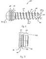
- FIG. 1is a perspective view of a fixed locking screw according to a preferred embodiment of the present invention
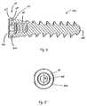
- FIG. 2is a plan view of a fixed locking screw according to a preferred embodiment of the present invention.
- FIG. 3is a detail view of the head of a fixed locking screw according to a preferred embodiment of the present invention.
- FIG. 5is a top view of a fixed locking screw according to a preferred embodiment of the present invention.
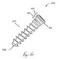
- FIG. 6is a perspective view of a variable locking screw according to a preferred embodiment of the present invention.
- FIG. 7is a plan view of a variable locking screw according to a preferred embodiment of the present invention.
- FIG. 8is a detail view of the head of a variable locking screw according to a preferred embodiment of the present invention.
- FIG. 10is a top view of a variable locking screw according to a preferred embodiment of the present invention.
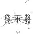
- FIG. 12is a plan view of the locking ring of FIG. 11 according to a preferred embodiment of the present invention.
- FIG. 13is a cross-sectional view of the locking ring of FIG. 11 according to a preferred embodiment of the present invention.
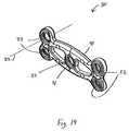
- FIG. 14is a perspective view of a plate according to a preferred embodiment of the present invention.
- FIG. 15is a bottom view of the plate of FIG. 14 according to a preferred embodiment of the present invention.
- FIG. 16is a cross-sectional view of a plate according to a preferred embodiment of the present invention.
- FIG. 17is a detailed sectional view of a plate through-hole according to a preferred embodiment of the present invention.
- FIG. 18is a detailed cross-sectional view of a plate through-hole having a fixed screw according to a preferred embodiment of the present invention inserted therein;
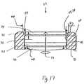
- FIG. 19is a detailed cross-sectional view of a plate through-hole with a variable screw according to a preferred embodiment of the present invention inserted therein after angulation has occurred;
- FIG. 20is a top plan view of a sleeve for installing a locking ring on a fixed screw, according to a preferred embodiment
- FIG. 21is a section view of the sleeve of FIG. 20 ;
- FIG. 22is a perspective view of a plate having inserted therein a fixed locking screw and depicting a variable locking screw being inserted therein, according to a preferred embodiment of the present invention.
- FIG. 23is a detailed cross-sectional view of an alternative embodiment of a plate having an insert coupled with the plate, wherein the insert contains a through-hole according to the present invention.
- FIG. 1depicts, in general form, a locking screw according to a preferred embodiment.
- FIGS. 1-5shows a fixed locking screw 100 as distinguished from FIGS. 6-10 which depict a variable locking screw 200 (to be described below, wherein the variable locking screw 200 has a modified head 210 and shank 220 ).
- the numeral 10shall refer to a locking screw of the present invention without regard for whether it is of the fixed type or the variable type. Each of these types of screws will be described below.
- the fixed locking screw 100generally comprises a head 110 , a shank 120 , and a threaded section 130 . Each of these sections has a proximal end and a distal end, the proximal end being defined as that end closest the head 110 of the locking screw 100 .
- the locking screw 100may be made of various materials, including metallic and non-metallic, depending on the application involved and the stresses expected in vivo. In the preferred embodiment relating to cervical implant systems, the screw 100 is made of implant grade titanium (Ti-6A1-4V) per ASTM F-136.
- the threaded section 130can comprise various forms of threads 131 , including but not limited to cancellous, cortical, and machine screw threads.
- the threads 131may be self-tapping or non-self-tapping.
- the threaded section 130comprises a major diameter 132 , defined as the outer-most diameter of the threads 131 , and a minor diameter 133 defined as the innermost or root diameter of the threads 131 .
- FIG. 3shows a close-up view of the head 110 and shank 120 .
- the shank 120is located between the threaded section 130 and the head 110 .
- the shank 120preferably comprises a first region, termed a shoulder 121 , and a second region, termed a shoulder taper 122 .
- the shoulder taper 122is adjacent the proximal end of the threaded section 130 .
- the head 110preferably further comprises three regions: an upper region 111 , a groove 112 , and a lower region 113 .
- the upper region 111is a cylindrical section having a diameter and a height. Therefore, when viewed in cross-section the upper region 111 has parallel sidewalls.
- the upper region 111may be conical, spherical, or of some other shape such that the upper region 111 has a first diameter at the proximal end and a second diameter adjacent the groove 112 . In such embodiments, it is conceivable that the first diameter can be greater than the second diameter, or vice versa.
- the upper region 111is a cylindrical section, however, it is obvious that the first diameter is equal to the second diameter, as the sidewalls are parallel in cross-section. It should be noted that the dimensions of the upper region 111 are dependent on the application, the materials used, and the stresses expected at that location. Therefore, the dimensions may vary significantly, from dimensions on the order of about a millimeter for anterior cervical applications, to theoretically any dimension for other, larger applications. In the preferred fixed screw embodiment, the upper region 111 has a height of approximately 0.58 mm (0.023 inches) and a diameter of approximately 4.79 mm (0.1886 inches).
- the groove 112is a section of reduced diameter that receives a locking ring 300 .
- the groove 112has a diameter and a height.
- the diameter of the groove 112is less than the internal diameter of the locking ring 300 (described below).
- the diameter of the groove 112is approximately 3.69 mm (0.145 inches).
- the height of the groove 112is approximately 0.51 mm (0.020 inches).
- the dimensions of the groove 112are similarly variable.
- the head 110further comprises a lower region 113 having a proximal end and a distal end.
- the proximal end of the lower region 113is adjacent the distal end of the groove 112 .
- the proximal end of the lower region 113is a cylindrical section having a diameter and a height. Therefore, when viewed in cross-section, the lower region 113 has parallel sidewalls.
- the lower region 113may also take on a non-cylindrical shape in alternative embodiments. In such embodiments, the lower region 113 may have a first diameter adjacent the groove 112 and a second diameter adjacent the shank 120 , wherein the first and second diameters are not equal.
- the first and second diameters of the lower region 113are equal.
- the distal end of the lower region 113has a chamfer having a diameter, wherein the chamfer acts as a guide when the screw is inserted.
- the diameter of the lower section 113is approximately 4.67 mm (0.184 inches).
- the height of the lower region 113is approximately 0.64 mm (0.025 inches).
- the dimensions of the lower region 113are similarly variable.
- the shank 120 of the screw 100likewise has a proximal end and a distal end.
- the proximal end of the shank 120is adjacent the distal end of the lower region 113 .
- the shank 120comprises at its proximal end a shoulder 121 having a uniform diameter, and therefore parallel sidewalls when viewed in cross-section.
- the diameter of the shoulder 121is preferably equal to the diameter of the chamfer of the lower region 113 .
- the shank 120comprises at its distal end a shoulder taper 122 .
- the purpose of the shoulder taper 122is to engage an exit section of a through-hole in a plate member (to be described below).
- the threaded section 130comprises threads 131 , and has a proximal end and a distal end.
- the distal end of the threaded section 130is the tip 134 of the screw 100 .
- the proximal end of the threaded section 130is adjacent the distal end of the shoulder taper 122 of the shank 120 .
- the threads 131may take many shapes and forms, depending in part on the type of application to which the screw is to be applied. In the preferred embodiment applicable to anterior cervical bone implant use, the threads 131 may be any type of cancellous bone thread, and can have a self-tapping region 135 if desired.
- the threaded section 130has a major diameter 132 and a minor diameter 133 .
- the major diameter 132is the maximum outside diameter of a line tangent to each flute 136 of the threaded section 130 .
- the minor diameter 133 or root diameteris the minimum diameter of the threads 131 , and can be understood to correspond with an imaginary shank portion extending throughout the length of the threaded section 130 .
- the major diameter 132is no greater than the diameter of the shoulder 121 of the shank 120 . This is to facilitate installing the locking ring 300 (to be described below).
- the head 110 of the screw 100further comprises an internal cavity 114 that receives the driving end of a driving instrument.
- the internal cavity 114preferably comprises two sections: a first cavity section 115 and a second cavity section 116 .
- the first cavity section 115has an open entrance section and an open exit section, and comprises a female geometric cavity. This geometric cavity may take many shapes and sizes, including, but not limited to, slotted, cylindrical, tapered cylindrical, and any regular or irregular open polygonal shape.
- the first cavity section 115comprises an internal hexagonal female opening that can receive a hex-headed male driving instrument.
- the second cavity section 116is adjacent the exit section of the first cavity section 115 and preferably comprises an internal threaded section to receive male threads of a driving instrument. It should be noted that the second cavity section 116 need not comprise internal threads, but could comprise any open geometric shape that can releasably receive a driving instrument.
- the male threads of the driving instrumentcan be used to engage the female threads in the second cavity section 116 , thereby drawing the screw 10 tight to the driving instrument. This is best seen in FIG. 22 .
- the female threads in the second cavity section 116can be used with a screw extraction device for removing a fastener 10 from the plate 30 .
- the locking ring 300comprises a generally annular ring having a break 301 in its circumference, wherein the break 301 defines two opposing ring faces 302 , 303 .
- the locking ring 300may take shapes that are not generally circular, but an annular ring is preferred.
- the locking ring 300generally has an outer diameter 304 and an inner diameter 305 which are preferably concentric about an imaginary centroidal axis. The inner diameter 305 thereby defines an opening 306 through which a screw 10 may be inserted in similar fashion to a standard washer.
- the locking ring 300further comprises a trailing surface 307 and a leading surface 308 .
- the trailing surface 307is flat and is the opening through which the tip 134 of the screw 10 is first inserted.
- the leading surface 308has a radius or chamfer 309 about its outer diameter 304 .
- the locking ring 300is designed to be inserted into the groove 112 in the head 110 of the screw 100 .
- the inner diameter 305 of the locking ring 300is greater than the diameter of the groove 112 of the head 110 , but is less than the diameter of the cylindrical section of the lower region 113 of the head 110 , and additionally is less than the maximum diameter of the upper region 111 of the head 110 .
- the outer diameter 304 of the locking ring 300is greater than both the diameter of the upper region 111 of the head 110 and the diameter of the cylindrical section of the lower region 113 of the head 110 . This ensures that, when the locking ring 300 is installed in the screw head 110 , the locking ring 300 resides within the groove 112 of the head 110 .
- the locking ringmay be made from many materials, including metallic and non-metallic. In the preferred embodiment relating to cervical implant applications, the preferred material for the locking ring is an implant grade titanium (Ti-6A1-4V) per ASTM F-136.
- the diameter of both the shoulder 121 and the head 110affect the amount the screw 100 is able to toggle within the through-hole 32 .
- the locking ring 300also plays a role in controlling the variability of the screw 100 . If the force from screw toggling is transmitted through the locking ring 300 to the upper region 111 of the head 110 instead of the shank 120 of the screw 100 , the locking ring 300 acting on the upper region 111 can cause the upper region 111 to fail after many cycles. As a result, a balance is preferable between the tolerance for mis-angled entry of the screw 100 and the risk for fatigue failure of the upper region 111 of the head 110 . A preferable balance is achieved when the shoulder 121 diameter is 4.32 mm (0.170 inches) and the diameter of the head 110 is 4.85 mm (0.191 inches).
- the sleeve 150has a proximal end 151 , a distal end 152 , and a middle portion 153 .
- the sleeve 150is basically an annular cylindrical member defining an opening 160 therethrough.
- the proximal end 151 of the sleeve 150has a straight sidewall portion 154 extending from the proximal end 151 to the middle portion 153 , wherein the straight sidewall portion 154 has an outer diameter and an inner diameter.
- the outer diameter of the straight sidewall portion 154is preferably equal to the diameter of the cylindrical section of the lower region 113 of the head 110 . In the preferred embodiment, the outer diameter of the straight sidewall portion 154 is approximately 4.67 mm (0.184 inches).
- the inner diameter of the straight sidewall portion 154is preferably equal to the diameter of the shoulder 121 . In the preferred embodiment, the inner diameter is approximately 4.32 mm (0.170 inches).
- the straight sidewall portion 154is connected to a tapered sidewall portion 155 at the middle portion 153 .
- the tapered sidewall portion 155has an outer surface 156 and an inner surface 157 .
- the inner surface 157is tapered at the same angle as that of the shoulder taper 122 of the fastener 100 . In the preferred embodiment, this taper is approximately 10°.
- the inner surface 157 of the preferred embodimenthas a maximum diameter of approximately 4.32 mm (0.170 inches) and a minimum diameter at the distal end 152 of approximately 4.06 mm (0.160 inches).
- the outer surface 156is also tapered, but is preferably tapered at a greater angle than is the inner surface 157 .
- the taper of the outer surface 156is so provide a sort of ramp for the locking ring 300 to slide along, thus creating the radial force necessary to expand the locking ring 300 and allow it to be placed into the groove 112 .
- the maximum diameter of the outer surface 156is approximately 4.67 mm (0.184 inches) at the middle portion 153
- the minimum diameteris approximately 4.32 mm (0.170 inches) at the distal end 152 .
- the tip 134 of the screw 100is first inserted through the opening 160 in the proximal end 151 of the sleeve 150 .
- the sleeve 150is then slid along the screw 100 until the proximal end 151 of the sleeve 150 rests against the distal end of the lower region 113 of the head 110 of the screw 100 .
- the tip 134 of the screw 100is inserted through the opening 306 of the trailing surface 307 of the locking ring 300 .
- the locking ring 300is then moved along the length of the screw 100 toward the proximal end of the screw 100 .
- the locking ring 300Because the inner diameter 305 of the locking ring 300 is greater than the major diameter 132 of the threaded section 130 , and is greater than the diameter of the shoulder 121 of the shank 120 , the locking ring 300 easily is moved along the length of the screw 10 . Once the locking ring 300 reaches the distal end 152 of the sleeve 150 , the inner diameter 305 of the locking ring 300 begins to engage the outer surface 156 of the tapered sidewall portion 155 of the sleeve 150 . As the locking ring 300 is moved farther along the screw 10 toward the proximal end of the screw 100 , the locking ring 300 begins to expand in a radial direction as the outer surface 156 diameter becomes progressively larger than the inner diameter 305 of the locking ring 300 .
- the radial expansionis allowed as a result of the break 301 in the circumference of the locking ring 300 .
- This radial deformationis within the elastic region of the locking ring 300 so that no significant permanent deformation of the locking ring 300 occurs.
- the inner diameter 305 of the locking ring 300has then reached its maximum value, which is equal to the outer diameter of the straight sidewall portion 154 of the sleeve 150 .
- the locking ring 300is then able to be slid toward the groove 112 which, as described above, has a smaller diameter than the inner diameter 305 of the locking ring 300 .
- the locking ring 300then elastically springs back to its original shape and, because of the aforementioned respective diameters of the upper region 111 , groove 112 , and lower region 113 , the locking ring 300 is retained within the groove 112 of the head 110 . Now the locking screw assembly is complete and is ready for insertion into a plate 30 .
- variable screw embodimentBefore describing the plate 30 , the variable screw embodiment shall be described herein. Variable screws are desirable in many implant applications because of the differential graft settlement or movement that is likely to occur after implantation. In certain regions, such differential movement must be accounted for in some fashion to alleviate the resultant increased stresses on the fastening members that can be imposed by such movement. As a result, the variable screw 200 of the present invention is designed to accommodate such movement while eliminating or reducing the resultant stresses. Such movement is typically on the order of approximately 1 to 15° about the longitudinal axis of the through-hole 32 .
- FIGS. 6-10depict the preferred embodiment of the variable locking screw 200 .
- the variable locking screw 200comprises, with several exceptions noted below, the same elements as the fixed locking screw 100 described above.
- the head 210comprises an upper region 211 , a groove 212 , and a lower region 213 .
- the shank 220comprises a shoulder 221
- the threaded section 230comprises threads 231 having a major diameter 232 and a minor diameter 233 , the distal end of which is a tip 234 .
- the upper region 211 of the head 210 of the variable screw 200comprises a generally spheroidal member having its outer sidewalls taking the shape of a portion of a sphere wherein the center of the sphere is located at a point along the longitudinal axis of the screw coincident with the center of the groove 212 .
- the proximal end of the upper region 211has a first diameter and the distal end of the upper-region 211 has a second diameter, wherein the second diameter is greater than the first diameter and wherein the surface connecting the first diameter to the second diameter is a portion of a sphere the imaginary center of which is located at the intersection of the longitudinal axis of the screw 200 and a radial plane therethrough located at the midheight of the groove 212 .
- the groove 212 of the variable screw 200is basically equivalent to the groove 112 of the fixed screw 100 .
- the lower region 213 of the variable screw 200comprises modifications from that of the fixed screw 100 .
- the lower region 213 of the head 210 of the variable screw 200comprises a generally spheroidal member having its outer sidewalls taking the shape of a portion of a sphere wherein the center of the sphere is located at a point along the longitudinal axis of the screw disposed slightly toward the proximal end of the screw 200 from the center of the groove 212 .
- the imaginary center of this sphereis approximately 0.82 mm (0.032 inches) from the center of the groove 212 .
- the proximal end of the lower region 213has a first diameter and the distal end of the upper region 213 has a second diameter, wherein the first diameter is greater than the second diameter and wherein the surface connecting the first diameter to the second diameter is a portion of a sphere the imaginary center of which is located at the intersection of the longitudinal axis of the screw 200 and a radial plane therethrough located at approximately 0.82 mm (0.032 inches) from the midheight of the groove 212 .
- the shank 220 of the variable screw 200is slightly different than the shank 120 of the fixed screw 100 .
- the shoulder 221 of the variable screw 200has a diameter that is very nearly equal to the major diameter 232 of the threads of the variable screw 200 . As a result, there is no need for a shoulder taper on the variable screw 200 .
- the shoulder 221 diameteris what controls the amount of toggle or variability allowed in the variable screw 200 .
- variable screw 200comprises a partially spherical lower region 213 , there is no need to utilize the sleeve 150 in order to install the locking ring 300 , as was the case for the fixed screw 100 (due to the fact that the lower region 113 of the fixed screw 100 comprises a cylindrical section). Rather, to install the locking ring 300 in the head 210 of the variable screw 200 , the tip 234 of the screw 200 is first inserted through the opening 306 of the trailing surface 307 of the locking ring 300 . The locking ring 300 is then moved along the length of the screw 200 toward the proximal end of the screw 200 .
- the locking ring 300Because the inner diameter 305 of the locking ring 300 is greater than the major diameter 232 of the threaded section 230 , and is greater than the diameter of the shoulder 221 of the shank 220 , the locking ring 300 easily is moved along the length of the screw 200 . Once the locking ring 300 reaches the lower region 213 of the head 210 , the inner diameter 305 of the locking ring 300 begins to engage the outer spherical surface of the lower region 213 . As the locking ring 300 is moved farther along the screw 200 toward the proximal end of the screw 200 , the locking ring 300 begins to expand in a radial direction as the spherical surface diameter becomes progressively larger than the inner diameter 305 of the locking ring 300 .
- the radial expansionis allowed as a result of the break 301 in the circumference of the locking ring 300 .
- This radial deformationis within the elastic region of the locking ring 300 so that no permanent deformation of the locking ring 300 occurs.
- the locking ring 300surpasses the first diameter of the lower region 213 of the head 210 , it reaches the groove 212 which, as described above, has a smaller diameter than the inner diameter 305 of the locking ring 300 .
- the locking ring 300then elastically springs back to its original shape and, because of the aforementioned respective diameters of the upper region 211 , groove 212 , and lower region 213 , the locking ring 300 is retained within the groove 212 of the head 210 .
- the locking screw assemblyis complete and is ready for insertion into a plate 30 .
- the plate 30is a general term for the members into which the locking screws of the present invention are to be inserted. It is contemplated that the plate 30 may take various shapes, sizes, and forms, depending upon the type of use to be employed. In addition, it is contemplated that the plate 30 may be unrelated to medical implant devices. However, to more easily understand the present invention, the plate 30 will be described as a cervical fixation plate having an anterior (upper) surface 31 and a posterior (lower) surface 41 and a plurality of fastener through-holes 32 therein.
- the plate 30 shown in FIG. 14is a two-level plate that spans two intervertebral disc levels. It should be understood that the plate 30 can also be a one level plate (spanning only one disc level) or any higher multiple level, the size of the plate 30 and the number of fastener through-holes 32 being adjusted accordingly.
- Each of the through-holes 32comprises an imaginary longitudinal axis 33 perpendicular to the surface of the plate 30 through which the screws 10 will be inserted.
- FIGS. 14 through 16depict a generalized cervical plate to facilitate this description. The portion of the plate 30 of interest herein is the through-hole 32 .
- FIG. 17depicts a cross-section of a typical through-hole 32 according to the preferred embodiment.
- the through-hole 32preferably comprises multiple sections.
- the through-hole 32comprises an entrance 34 having a proximal end located at the anterior surface 31 of the plate 30 .
- the entrance 34further comprises a distal end located at a depth within the through-hole 32 .
- the second sectionis a collar section 35 having its proximal end adjacent the distal end of the entrance 34 .
- the third sectionis an undercut 36 having its proximal end adjacent the distal end of the collar section 35 .
- the fourth sectionis a ramp section 37
- the fifth sectionis an exit 38 .
- each section of the through-hole 32is adjacent the preceding section as one travels from the anterior surface 31 of the plate 30 toward posterior surface 41 of the plate 30 .
- Each sectionhas a proximal end and a distal end, the proximal end of each being defined as that end closest to the anterior surface 31 of the plate 30 .
- the entrance 34has a first diameter 44 at or near its proximal end and a second diameter 54 at its distal end, wherein the first diameter 44 is greater than the second diameter 54 .
- the tapered sidewall 64serves the important function of providing the surface along which the leading surface 308 of the locking ring 300 contacts when the locking screw 100 , 200 is inserted into the through-hole 32 .
- the tapered sidewall 64is a lead chamfer 74 that interacts with the leading surface 308 of the locking ring 300 ( FIG.
- the lead chamfer 74provides the necessary radial compressive force to begin radially compressing the locking ring 300 , thereby elastically reducing the outer diameter 304 of the locking ring 300 .
- the collar section 35comprises a cylindrical opening having parallel sidewalls.
- the diameter of the collar section 35is greater than the inner diameter 305 of the locking ring 300 , and represents the maximum extent to which the outer diameter 304 of the locking ring 300 is to be radially compressed.
- the undercut 36also comprises a cylindrical opening having parallel sidewalls, but the diameter of the cylindrical opening of the undercut 36 is greater than the diameter of the cylindrical opening of the collar section 35 .
- a lip 46having, preferably, a 90° angle with respect to the parallel sidewalls of the undercut 36 .
- This lip 46provides a surface against which the trailing surface 307 of the locking ring 300 will bear when forces are applied on the screw 10 that would tend to remove the screw 10 from the through-hole 32 .
- the diameter of the undercut 36is slightly less than the outer diameter 304 of the locking ring 300 in its normal, uncompressed state.
- the exit 38comprises a ramped section 37 at its proximal end adjacent a cylindrical opening 48 at its distal end.
- the ramp section 37is provided to keep the locking ring 300 compressed while the variable screw 200 is toggled or angulated within the through-hole 32 .
- the ramp 37allows the longitudinal axis of the variable screw 200 to attain various angles of inclination from the longitudinal axis 33 of the through-hole 32 .
- the head 210 and shank 220 of the variable screw 200allows the outer diameter 304 of the locking ring 300 to move along and interact with the surface of the ramp 37 .
- FIG. 19shows how a variable screw 200 is allowed to angulate within the through-hole 32 .
- the spherical surface of the lower region 213rests on and rotates about the upper surface of the exit 38 .
- FIG. 18shows how a fixed screw 100 is prevented from angulation in the same through-hole 32 as a result of the size and shape of the head 110 and shank 120 of the fixed screw 100 .
- the shoulder 121 of the shank 120fits within the exit 38 and has no room for movement.
- the fixed screw 100cannot angulate about the longitudinal axis 31 of the through-hole 32 .
- the plate 30may be made from various materials including metallic and non-metallic.
- the preferred materialis implant grade titanium (Ti-6A1-4V), per ASTM F-136.
- FIG. 23shows an alternative embodiment of the plate 30 enables the use of non-metallic'material for the plate and the use of a metallic screw 10 .
- a metallic screw against a non-metallic plateis disfavored.
- One materialcan create destruction or wear debris in the other material.
- a titanium screwmay shear a particle off from a nonmetallic plate. This is undesirable for many reasons, including the fact that the Food and Drug Administration has raised concerns about the deleterious effects of wear debris associated with implants.
- the plate 30 Ahas an insert 30 B molded therein.
- the plate 30 Ais made of inert material, such as a carbon composite
- the insert 30 Bis made of any of various appropriate metals, such as titanium, and molded into the plate 30 A.
- the use of the insert 30 Benables the same material—titanium in the preferred alternative embodiment—to be used for the fastener 10 and for the area within the through-hole 32 which contacts the fastener 10 .
- the use of a separate insert 30 Bprovides great versatility. Many different configurations are possible for the plate 30 A and the insert 30 B.
- the use of a separate insert 30 Bprovides the ability to configure the through-hole 32 in a variety of ways, not just limited to the structure of the through-hole 32 described herein.
- the insert 30 Bmay be placed within the plate 30 A using in a variety of ways, including the use of threaded means, adhesives, molding techniques, ultrasonic welding, heat staking, compression fit techniques, and so forth. In the preferred alternative embodiment, the insert 30 B is fastened to the plate 30 A during the molding process in the forming of the plate 30 A.
- the first stepis to install the locking ring 300 on a screw (either a fixed screw 100 with the use of the sleeve 150 , or a variable screw 200 ), making sure that the flat trailing surface 307 of the locking ring 300 is facing the proximal end of the screw 10 .
- the locking screw 10is ready to be installed into the plate 30 .
- the area to be instrumentedhas already been dissected and prepared, and the plate size and shape has already been selected.
- the surgeonmay pre-drill or pre-awl a hole in the bone to be instrumented. Additionally, the surgeon may tap the drilled or awled hole in order to better accept the threads 131 of the screw 10 .
- the surgeonsecures the locking screw 10 to the driving instrument by, preferably, inserting the driving instrument into the first cavity section 115 and engaging the external threads of the driving device with the internal threads of the second cavity section 116 in the head 110 of the screw 10 . Having done this, the surgeon then inserts the locking screw 10 into a desired through-hole 32 in a plate 30 located at the region desired to be instrumented. The surgeon installs the screw by engaging the tip 134 of the screw 10 with a portion of bone, and begins rotatably threading the screw 10 into the bone.
- the screw 10As the surgeon rotatably threads the screw 10 into the bone, the screw 10 progressively enters the bone. The surgeon continues this until the chamfer 309 on the leading surface 308 of the locking ring 300 begins interacting with the lead chamfer 74 of the entrance 34 of the through-hole 32 . Upon further insertion, the surgeon is able to continually radially compress the locking ring 300 as it passes through the collar section 35 .
- the locking ring 300Once the locking ring 300 has exited the collar section 35 , it expands to fit the diameter of the undercut 36 of the through-hole 32 .
- the surgeoncan insert any number of fixed or variable screws 100 , 200 in this manner, thereby securely fastening a bone implant to one or more bone segments.
- the screw 10is thereby effectively and securely retained in the plate 30 . Because the trailing surface 307 of the locking ring 300 is flat, and because the force required to remove the screw 10 from the through-hole 32 is relatively large as a result of the lip 46 , the locking screw system prevents screw backout or migration.
- the leading surface 308is radiused and because of the presence of the lead chamfer 74 , the force required to install the screw 10 into the bone is relatively minimal and requires only a low torque on the part of the surgeon. This significantly reduces the possibility that the surgeon will strip the threads 131 in poor quality bone.
Landscapes
- Health & Medical Sciences (AREA)
- Orthopedic Medicine & Surgery (AREA)
- Surgery (AREA)
- Life Sciences & Earth Sciences (AREA)
- Heart & Thoracic Surgery (AREA)
- Nuclear Medicine, Radiotherapy & Molecular Imaging (AREA)
- Engineering & Computer Science (AREA)
- Biomedical Technology (AREA)
- Neurology (AREA)
- Medical Informatics (AREA)
- Molecular Biology (AREA)
- Animal Behavior & Ethology (AREA)
- General Health & Medical Sciences (AREA)
- Public Health (AREA)
- Veterinary Medicine (AREA)
- Surgical Instruments (AREA)
- Prostheses (AREA)
Abstract
Description
Claims (32)
Priority Applications (1)
| Application Number | Priority Date | Filing Date | Title |
|---|---|---|---|
| US11/142,702US7780666B1 (en) | 2002-07-05 | 2005-06-01 | Fixed and variable locking fixation assembly |
Applications Claiming Priority (2)
| Application Number | Priority Date | Filing Date | Title |
|---|---|---|---|
| US10/190,257US7001389B1 (en) | 2002-07-05 | 2002-07-05 | Fixed and variable locking fixation assembly |
| US11/142,702US7780666B1 (en) | 2002-07-05 | 2005-06-01 | Fixed and variable locking fixation assembly |
Related Parent Applications (1)
| Application Number | Title | Priority Date | Filing Date |
|---|---|---|---|
| US10/190,257DivisionUS7001389B1 (en) | 2002-07-05 | 2002-07-05 | Fixed and variable locking fixation assembly |
Publications (1)
| Publication Number | Publication Date |
|---|---|
| US7780666B1true US7780666B1 (en) | 2010-08-24 |
Family
ID=35810557
Family Applications (4)
| Application Number | Title | Priority Date | Filing Date |
|---|---|---|---|
| US10/190,257Expired - LifetimeUS7001389B1 (en) | 2002-07-05 | 2002-07-05 | Fixed and variable locking fixation assembly |
| US11/142,854Expired - LifetimeUS7785327B1 (en) | 2002-07-05 | 2005-06-01 | Fixed and variable locking fixation assembly |
| US11/142,702Expired - LifetimeUS7780666B1 (en) | 2002-07-05 | 2005-06-01 | Fixed and variable locking fixation assembly |
| US11/294,185Expired - LifetimeUS7766911B1 (en) | 2002-07-05 | 2005-12-05 | Fixed and variable locking fixation assembly |
Family Applications Before (2)
| Application Number | Title | Priority Date | Filing Date |
|---|---|---|---|
| US10/190,257Expired - LifetimeUS7001389B1 (en) | 2002-07-05 | 2002-07-05 | Fixed and variable locking fixation assembly |
| US11/142,854Expired - LifetimeUS7785327B1 (en) | 2002-07-05 | 2005-06-01 | Fixed and variable locking fixation assembly |
Family Applications After (1)
| Application Number | Title | Priority Date | Filing Date |
|---|---|---|---|
| US11/294,185Expired - LifetimeUS7766911B1 (en) | 2002-07-05 | 2005-12-05 | Fixed and variable locking fixation assembly |
Country Status (1)
| Country | Link |
|---|---|
| US (4) | US7001389B1 (en) |
Cited By (15)
| Publication number | Priority date | Publication date | Assignee | Title |
|---|---|---|---|---|
| US20100114097A1 (en)* | 2007-04-27 | 2010-05-06 | Synthes Usa, Llc | Implant Devices Constructed with Metallic and Polymeric Components |
| US8128703B2 (en) | 2007-09-28 | 2012-03-06 | Depuy Products, Inc. | Fixed-bearing knee prosthesis having interchangeable components |
| US20120259367A1 (en)* | 2011-04-08 | 2012-10-11 | Kyphon Sarl | Lumbar-sacral implant allowing variable angle fixation |
| US8287601B2 (en) | 2010-09-30 | 2012-10-16 | Depuy Products, Inc. | Femoral component of a knee prosthesis having an angled cement pocket |
| US8317870B2 (en) | 2010-09-30 | 2012-11-27 | Depuy Products, Inc. | Tibial component of a knee prosthesis having an angled cement pocket |
| WO2013109813A1 (en)* | 2012-01-18 | 2013-07-25 | Globus Medical, Inc. | Securing fasteners |
| US8771324B2 (en) | 2011-05-27 | 2014-07-08 | Globus Medical, Inc. | Securing fasteners |
| US8940030B1 (en) | 2011-01-28 | 2015-01-27 | Nuvasive, Inc. | Spinal fixation system and related methods |
| US9011547B2 (en) | 2010-01-21 | 2015-04-21 | Depuy (Ireland) | Knee prosthesis system |
| US9101426B2 (en) | 2012-10-11 | 2015-08-11 | Stryker Trauma Sa | Cable plug |
| US9204967B2 (en) | 2007-09-28 | 2015-12-08 | Depuy (Ireland) | Fixed-bearing knee prosthesis having interchangeable components |
| US9277946B2 (en) | 2011-09-06 | 2016-03-08 | Amendia, Inc. | Spinal fusion system |
| US9398956B2 (en) | 2007-09-25 | 2016-07-26 | Depuy (Ireland) | Fixed-bearing knee prosthesis having interchangeable components |
| US10499968B2 (en) | 2014-08-08 | 2019-12-10 | Stryker European Holdings I, Llc | Cable plugs for bone plates |
| US10765527B2 (en) | 2017-09-29 | 2020-09-08 | Axiomed, LLC | Artificial disk with sensors |
Families Citing this family (188)
| Publication number | Priority date | Publication date | Assignee | Title |
|---|---|---|---|---|
| US7833250B2 (en) | 2004-11-10 | 2010-11-16 | Jackson Roger P | Polyaxial bone screw with helically wound capture connection |
| US7001389B1 (en) | 2002-07-05 | 2006-02-21 | Navarro Richard R | Fixed and variable locking fixation assembly |
| US8876868B2 (en) | 2002-09-06 | 2014-11-04 | Roger P. Jackson | Helical guide and advancement flange with radially loaded lip |
| CA2504215A1 (en) | 2002-10-28 | 2004-05-13 | Blackstone Medical, Inc. | Bone plate assembly provided with screw locking mechanisms |
| US20050187551A1 (en)* | 2002-12-02 | 2005-08-25 | Orbay Jorge L. | Bone plate system with bone screws fixed by secondary compression |
| US7780664B2 (en) | 2002-12-10 | 2010-08-24 | Depuy Products, Inc. | Endosteal nail |
| US7048739B2 (en)* | 2002-12-31 | 2006-05-23 | Depuy Spine, Inc. | Bone plate and resilient screw system allowing bi-directional assembly |
| US7914561B2 (en) | 2002-12-31 | 2011-03-29 | Depuy Spine, Inc. | Resilient bone plate and screw system allowing bi-directional assembly |
| US7175624B2 (en)* | 2002-12-31 | 2007-02-13 | Depuy Spine, Inc. | Bone plate and screw system allowing bi-directional assembly |
| US7341591B2 (en)* | 2003-01-30 | 2008-03-11 | Depuy Spine, Inc. | Anterior buttress staple |
| US7278997B1 (en) | 2003-03-07 | 2007-10-09 | Theken Spine, Llc | Instrument guide and implant holder |
| US7169150B2 (en)* | 2003-04-25 | 2007-01-30 | Warsaw Orthopedic, Inc. | Non-metallic orthopedic plate |
| US7377923B2 (en) | 2003-05-22 | 2008-05-27 | Alphatec Spine, Inc. | Variable angle spinal screw assembly |
| US8926637B2 (en) | 2003-06-13 | 2015-01-06 | Covidien Lp | Multiple member interconnect for surgical instrument and absorbable screw fastener |
| US8926670B2 (en) | 2003-06-18 | 2015-01-06 | Roger P. Jackson | Polyaxial bone screw assembly |
| US7776067B2 (en) | 2005-05-27 | 2010-08-17 | Jackson Roger P | Polyaxial bone screw with shank articulation pressure insert and method |
| US7766915B2 (en) | 2004-02-27 | 2010-08-03 | Jackson Roger P | Dynamic fixation assemblies with inner core and outer coil-like member |
| US8366753B2 (en) | 2003-06-18 | 2013-02-05 | Jackson Roger P | Polyaxial bone screw assembly with fixed retaining structure |
| US7967850B2 (en) | 2003-06-18 | 2011-06-28 | Jackson Roger P | Polyaxial bone anchor with helical capture connection, insert and dual locking assembly |
| US7309340B2 (en)* | 2003-06-20 | 2007-12-18 | Medicinelodge, Inc. | Method and apparatus for bone plating |
| US7625375B2 (en)* | 2003-08-06 | 2009-12-01 | Warsaw Orthopedic, Inc. | Systems and techniques for stabilizing the spine and placing stabilization systems |
| US7909860B2 (en)* | 2003-09-03 | 2011-03-22 | Synthes Usa, Llc | Bone plate with captive clips |
| US7306605B2 (en) | 2003-10-02 | 2007-12-11 | Zimmer Spine, Inc. | Anterior cervical plate |
| CA2449883A1 (en)* | 2003-11-18 | 2005-05-18 | Terray Corporation | Taper-lock bone screw fixation system |
| US8900277B2 (en) | 2004-02-26 | 2014-12-02 | Pioneer Surgical Technology, Inc. | Bone plate system |
| WO2005090800A1 (en)* | 2004-03-12 | 2005-09-29 | Gkn Driveline North America, Inc. | Bolt assembly |
| US9474560B2 (en) | 2004-04-08 | 2016-10-25 | Globus Medical, Inc | Load distribution crown |
| US7615069B2 (en)* | 2004-04-08 | 2009-11-10 | Globus Medical, Inc. | Load distribution crown |
| US7854752B2 (en) | 2004-08-09 | 2010-12-21 | Theken Spine, Llc | System and method for dynamic skeletal stabilization |
| US9615866B1 (en) | 2004-10-18 | 2017-04-11 | Nuvasive, Inc. | Surgical fixation system and related methods |
| US8926672B2 (en) | 2004-11-10 | 2015-01-06 | Roger P. Jackson | Splay control closure for open bone anchor |
| US8444681B2 (en) | 2009-06-15 | 2013-05-21 | Roger P. Jackson | Polyaxial bone anchor with pop-on shank, friction fit retainer and winged insert |
| US9168069B2 (en) | 2009-06-15 | 2015-10-27 | Roger P. Jackson | Polyaxial bone anchor with pop-on shank and winged insert with lower skirt for engaging a friction fit retainer |
| US9980753B2 (en) | 2009-06-15 | 2018-05-29 | Roger P Jackson | pivotal anchor with snap-in-place insert having rotation blocking extensions |
| US7799062B2 (en)* | 2004-11-30 | 2010-09-21 | Stryker Trauma S.A. | Self-guiding threaded fastener |
| US7931678B2 (en) | 2004-12-08 | 2011-04-26 | Depuy Spine, Inc. | Hybrid spinal plates |
| US7935137B2 (en) | 2004-12-08 | 2011-05-03 | Depuy Spine, Inc. | Locking bone screw and spinal plate system |
| US7736380B2 (en) | 2004-12-21 | 2010-06-15 | Rhausler, Inc. | Cervical plate system |
| US7527640B2 (en)* | 2004-12-22 | 2009-05-05 | Ebi, Llc | Bone fixation system |
| US7901437B2 (en) | 2007-01-26 | 2011-03-08 | Jackson Roger P | Dynamic stabilization member with molded connection |
| US20060235403A1 (en)* | 2005-03-17 | 2006-10-19 | Jason Blain | Flanged interbody fusion device with locking plate |
| US8070749B2 (en) | 2005-05-12 | 2011-12-06 | Stern Joseph D | Revisable anterior cervical plating system |
| WO2006124273A2 (en)* | 2005-05-12 | 2006-11-23 | Stern Joseph D | Revisable anterior cervical plating system |
| US20060293668A1 (en)* | 2005-06-10 | 2006-12-28 | Sdgi Holdings, Inc. | Bone screw locking mechanism and method of use |
| US7686806B2 (en)* | 2005-06-15 | 2010-03-30 | Stryker Spine | Anterior cervical plate |
| US7465313B2 (en)* | 2005-09-26 | 2008-12-16 | Depuy Spine, Inc. | Red light implant for treating degenerative disc disease |
| US8262713B2 (en) | 2005-09-26 | 2012-09-11 | Depuy Spine, Inc. | Red light implant for treating osteoporosis |
| US7887595B1 (en) | 2005-12-05 | 2011-02-15 | Nuvasive, Inc. | Methods and apparatus for spinal fusion |
| EP1962707A1 (en)* | 2005-12-21 | 2008-09-03 | Synthes GmbH | Resorbable anterior cervical plating system with screw retention mechanism |
| US9687282B2 (en)* | 2006-03-07 | 2017-06-27 | Orthohelix Surgical Designs, Inc. | Orthopedic plate having threaded holes for locking screws or pegs and non-threaded holes for a variable axis locking mechanism |
| WO2007109340A2 (en) | 2006-03-21 | 2007-09-27 | Axiom Orthopaedics, Inc. | Femoral and humeral stem geometry and implantation method for orthopedic joint reconstruction |
| US8025681B2 (en)* | 2006-03-29 | 2011-09-27 | Theken Spine, Llc | Dynamic motion spinal stabilization system |
| US20080097442A1 (en)* | 2006-06-29 | 2008-04-24 | Dixon Robert A | Method and device for improving the function of taper locks used for spinal stabilization |
| US8114162B1 (en) | 2006-08-09 | 2012-02-14 | Nuvasive, Inc. | Spinal fusion implant and related methods |
| USD708747S1 (en) | 2006-09-25 | 2014-07-08 | Nuvasive, Inc. | Spinal fusion implant |
| USD582040S1 (en) | 2006-10-05 | 2008-12-02 | Stryker Spine | Cervical plate |
| USD581535S1 (en) | 2006-10-05 | 2008-11-25 | Stryker Spine | Cervical plate |
| US8361130B2 (en) | 2006-10-06 | 2013-01-29 | Depuy Spine, Inc. | Bone screw fixation |
| US20080234692A1 (en) | 2007-03-06 | 2008-09-25 | Matt Brandt | Orthopedic jig, pin, and method |
| WO2008118295A2 (en)* | 2007-03-26 | 2008-10-02 | Laszlo Garamszegi | Bottom-loading pedicle screw assembly |
| US8702762B2 (en) | 2007-03-27 | 2014-04-22 | Depuy Spine, Inc. | Passive screw locking mechanism |
| US20080249569A1 (en)* | 2007-04-03 | 2008-10-09 | Warsaw Orthopedic, Inc. | Implant Face Plates |
| US8268000B2 (en)* | 2007-04-03 | 2012-09-18 | Warsaw Orthopedic, Inc. | Composite interbody spacer |
| US8425607B2 (en)* | 2007-04-03 | 2013-04-23 | Warsaw Orthopedic, Inc. | Anchor member locking features |
| EP2134279B1 (en) | 2007-04-19 | 2017-01-04 | Stryker European Holdings I, LLC | Hip fracture device with static locking mechanism allowing compression |
| US8398636B2 (en) | 2007-04-19 | 2013-03-19 | Stryker Trauma Gmbh | Hip fracture device with barrel and end cap for load control |
| US8979904B2 (en) | 2007-05-01 | 2015-03-17 | Roger P Jackson | Connecting member with tensioned cord, low profile rigid sleeve and spacer with torsion control |
| US9545275B2 (en) | 2007-05-18 | 2017-01-17 | Us Spine, Inc. | Medical device locking mechanisms and related methods and systems |
| US20090216282A1 (en)* | 2007-05-18 | 2009-08-27 | Blake Doris M | Systems and methods for retaining a plate to a substrate with an asynchronous thread form |
| US8840650B2 (en)* | 2007-05-18 | 2014-09-23 | Us Spine, Inc. | Cervical plate locking mechanism and associated surgical method |
| US8721693B2 (en)* | 2007-05-18 | 2014-05-13 | Us Spine, Inc. | Cervical plate locking mechanism and associated surgical method |
| US8864829B1 (en)* | 2007-07-02 | 2014-10-21 | Theken Spine, Llc | Spinal cage having deployable member |
| US10342674B2 (en) | 2007-07-02 | 2019-07-09 | Theken Spine, Llc | Spinal cage having deployable member |
| US12186201B2 (en) | 2007-07-02 | 2025-01-07 | Theken Spine, Llc | Spinal cage having deployable member |
| US8556944B2 (en)* | 2007-07-31 | 2013-10-15 | Stryker Spine | System and method for vertebral body plating |
| US20090177239A1 (en)* | 2007-08-06 | 2009-07-09 | Michael Castro | Cervical plate instrument kit |
| US8388666B2 (en)* | 2007-09-27 | 2013-03-05 | Biomet C.V. | Locking screw system with relatively hard spiked polyaxial bushing |
| USD597673S1 (en)* | 2008-01-08 | 2009-08-04 | Southern Spine, Llc | Shielded spinal stabilization plate |
| US8282675B2 (en)* | 2008-01-25 | 2012-10-09 | Depuy Spine, Inc. | Anti-backout mechanism |
| US9345517B2 (en) | 2008-02-02 | 2016-05-24 | Globus Medical, Inc. | Pedicle screw having a removable rod coupling |
| US8551144B2 (en)* | 2008-04-22 | 2013-10-08 | Collab Comlo, LLC | Bone plate system configurable as static or dynamic implant |
| WO2009132305A2 (en)* | 2008-04-24 | 2009-10-29 | Alpinespine Llc | Rotolock cervical plate locking mechanism |
| WO2009132302A1 (en) | 2008-04-25 | 2009-10-29 | Pioneer Surgical Technology, Inc. | Bone plate system |
| US20090275989A1 (en)* | 2008-05-01 | 2009-11-05 | Linares Medical Devices, Llc | Composite and surface mounted brace, kit and assembly for supporting a fractured bone |
| US9033985B2 (en) | 2008-05-01 | 2015-05-19 | Linares Medical Devices, Llc | Composite and surface mounted brace, kit and assembly for supporting a fractured bone |
| US8425514B2 (en)* | 2008-06-25 | 2013-04-23 | Westmark Medical, Llc. | Spinal fixation device |
| USD603506S1 (en)* | 2008-07-03 | 2009-11-03 | Theken Spine, Llc | Cervical plate |
| USD603963S1 (en)* | 2008-07-03 | 2009-11-10 | Theken Spine, Llc | Cervical plate |
| USD603504S1 (en)* | 2008-07-03 | 2009-11-03 | Theken Spine, Llc | Cervical plate |
| USD603962S1 (en)* | 2008-07-03 | 2009-11-10 | Theken Spine, Llc | Cervical plate |
| USD603507S1 (en)* | 2008-07-03 | 2009-11-03 | Theken Spine, Llc | Cervical plate |
| USD603510S1 (en)* | 2008-07-03 | 2009-11-03 | Theken Spine, Llc | Cervical plate |
| USD603961S1 (en)* | 2008-07-03 | 2009-11-10 | Theken Spine, Llc | Cervical plate |
| USD603511S1 (en)* | 2008-07-03 | 2009-11-03 | Theken Spine, Llc | Cervical plate |
| USD603505S1 (en)* | 2008-07-03 | 2009-11-03 | Theken Spine, Llc | Cervical plate |
| USD603509S1 (en)* | 2008-07-03 | 2009-11-03 | Theken Spine, Llc | Cervical plate |
| USD603503S1 (en)* | 2008-07-03 | 2009-11-03 | Theken Spine, Llc | Cervical plate |
| USD603964S1 (en)* | 2008-07-03 | 2009-11-10 | Theken Spine, Llc | Cervical plate |
| USD603508S1 (en)* | 2008-07-03 | 2009-11-03 | Theken Spine, Llc | Cervical plate |
| AU2010260521C1 (en) | 2008-08-01 | 2013-08-01 | Roger P. Jackson | Longitudinal connecting member with sleeved tensioned cords |
| WO2010045355A1 (en)* | 2008-10-14 | 2010-04-22 | K2M, Inc. | Semi-constrained screw and spinal plate assembly |
| US9301785B2 (en) | 2008-10-21 | 2016-04-05 | K2M, Inc. | Spinal buttress plate |
| US8241339B2 (en)* | 2009-02-13 | 2012-08-14 | Globus Medical, Inc. | Orthopedic anchor assembly |
| US8246664B2 (en)* | 2009-02-24 | 2012-08-21 | Osteomed Llc | Multiple bone fusion plate |
| US8366719B2 (en) | 2009-03-18 | 2013-02-05 | Integrated Spinal Concepts, Inc. | Image-guided minimal-step placement of screw into bone |
| US9220547B2 (en) | 2009-03-27 | 2015-12-29 | Spinal Elements, Inc. | Flanged interbody fusion device |
| CN102387754B (en) | 2009-04-08 | 2015-08-19 | 斯特赖克特劳马股份公司 | Mixing hone lamella |
| US8529608B2 (en) | 2009-04-28 | 2013-09-10 | Osteomed Llc | Bone plate with a transfixation screw hole |
| US8282676B2 (en)* | 2009-05-28 | 2012-10-09 | Griffin T Hall | Tapered thread root transition on cortical bone fastener |
| CN103826560A (en) | 2009-06-15 | 2014-05-28 | 罗杰.P.杰克逊 | Polyaxial Bone Anchor with Socket Stem and Winged Inserts with Friction Fit Compression Collars |
| US9668771B2 (en) | 2009-06-15 | 2017-06-06 | Roger P Jackson | Soft stabilization assemblies with off-set connector |
| US11229457B2 (en) | 2009-06-15 | 2022-01-25 | Roger P. Jackson | Pivotal bone anchor assembly with insert tool deployment |
| US8998959B2 (en) | 2009-06-15 | 2015-04-07 | Roger P Jackson | Polyaxial bone anchors with pop-on shank, fully constrained friction fit retainer and lock and release insert |
| US11464549B2 (en) | 2009-06-15 | 2022-10-11 | Roger P. Jackson | Pivotal bone anchor assembly with horizontal tool engagement grooves and insert with upright arms having flared outer portions |
| JP5662442B2 (en) | 2009-07-24 | 2015-01-28 | スパイナル・ユーエスエー・エルエルシー | Bone plate screw block system and method |
| KR20120082397A (en)* | 2009-07-24 | 2012-07-23 | 스파이널 유에스에이 엘엘씨 | Bone plate system and methods of using the same |
| US8574271B2 (en)* | 2009-07-29 | 2013-11-05 | Paul Andrew Glazer | Fixation plate screw retention |
| FR2949317B1 (en)* | 2009-09-02 | 2012-04-13 | Creaspine | IMPLANT ASSEMBLY FOR BONE FASTENING, PLATE AND SCREW TYPE |
| US8496692B2 (en)* | 2009-09-21 | 2013-07-30 | Jmea Corporation | Locking securing member |
| EP2485654B1 (en) | 2009-10-05 | 2021-05-05 | Jackson P. Roger | Polyaxial bone anchor with non-pivotable retainer and pop-on shank, some with friction fit |
| USD734853S1 (en) | 2009-10-14 | 2015-07-21 | Nuvasive, Inc. | Bone plate |
| WO2011057079A1 (en)* | 2009-11-05 | 2011-05-12 | K2M, Inc. | Semi-constrained bone screw |
| US8771325B2 (en)* | 2009-11-20 | 2014-07-08 | T. Hall Griffin | Tapered threaded orthopedic fastener engaging predetermined radial preloads |
| US8414629B2 (en)* | 2009-11-20 | 2013-04-09 | T. Hall Griffin | Limiting radial preloads in securing an orthopedic fastener |
| US8409261B2 (en)* | 2009-11-20 | 2013-04-02 | T. Hall Griffin | Engaging predetermined radial preloads in securing an orthopedic fastener |
| US8486116B2 (en) | 2010-01-08 | 2013-07-16 | Biomet Manufacturing Ring Corporation | Variable angle locking screw |
| US8142477B2 (en)* | 2010-01-21 | 2012-03-27 | Warsaw Orthopedic, Inc. | Retaining system |
| US8425576B2 (en)* | 2010-01-26 | 2013-04-23 | Westmark Medical, Llc. | Bone screw retention mechanism |
| USD642270S1 (en)* | 2010-02-24 | 2011-07-26 | Globus Medical, Inc. | Rigid orthopedic screw |
| US8647369B2 (en) | 2010-05-19 | 2014-02-11 | Josef E. Gorek | Minimal profile anterior bracket for spinal fixation |
| USD643121S1 (en) | 2010-05-27 | 2011-08-09 | Ebi, Llc | Orthopedic wrist spanning bone plate |
| USD646785S1 (en) | 2010-05-27 | 2011-10-11 | Ebi, Llc | Orthopedic volar bone plate |
| US20120136398A1 (en)* | 2010-05-28 | 2012-05-31 | Jean-Pierre Mobasser | Awl-tipped pedicle screw and method of implanting same |
| US20140243912A1 (en)* | 2010-05-28 | 2014-08-28 | Jean-Pierre Mobasser | Awl-tipped pedicle screw and method of implanting same |
| US8858603B1 (en) | 2010-06-09 | 2014-10-14 | Choice Spine, L.P. | Cervical plate with screw retention clip |
| US8390205B2 (en) | 2010-09-01 | 2013-03-05 | Osram Sylvania Inc. | LED control using modulation frequency detection techniques |
| US8753396B1 (en) | 2010-09-13 | 2014-06-17 | Theken Spine, Llc | Intervertebral implant having back-out prevention feature |
| AU2011324058A1 (en) | 2010-11-02 | 2013-06-20 | Roger P. Jackson | Polyaxial bone anchor with pop-on shank and pivotable retainer |
| EP2460484A1 (en)* | 2010-12-01 | 2012-06-06 | FACET-LINK Inc. | Variable angle bone screw fixation assembly |
| ES2461843T3 (en) | 2010-12-23 | 2014-05-21 | Biedermann Technologies Gmbh & Co. Kg | Bone anchoring device |
| US8728129B2 (en) | 2011-01-07 | 2014-05-20 | Biomet Manufacturing, Llc | Variable angled locking screw |
| US9480510B2 (en) | 2011-03-23 | 2016-11-01 | Spinecraft, LLC | Devices, systems and methods of attaching same to the spine |
| JP5865479B2 (en) | 2011-03-24 | 2016-02-17 | ロジャー・ピー・ジャクソン | Multiaxial bone anchor with compound joint and pop-mounted shank |
| DE102011051975B4 (en)* | 2011-07-20 | 2023-01-12 | Ulrich Gmbh & Co. Kg | implant |
| EP2586387A1 (en) | 2011-10-31 | 2013-05-01 | Tornier Orthopedics Ireland Ltd. | Bone reamer |
| US11123117B1 (en) | 2011-11-01 | 2021-09-21 | Nuvasive, Inc. | Surgical fixation system and related methods |
| US9522023B2 (en)* | 2011-12-09 | 2016-12-20 | Zimmer Gmbh | Orthopedic plate, orthopedic device, method of coupling bone segments, and method of assembling an orthopedic plate |
| US9198769B2 (en) | 2011-12-23 | 2015-12-01 | Pioneer Surgical Technology, Inc. | Bone anchor assembly, bone plate system, and method |
| US8911479B2 (en) | 2012-01-10 | 2014-12-16 | Roger P. Jackson | Multi-start closures for open implants |
| US20130319866A1 (en) | 2012-05-29 | 2013-12-05 | Lucy Elizabeth Browning | Anodized films |
| WO2014008229A1 (en)* | 2012-07-03 | 2014-01-09 | Smith & Nephew, Inc. | Orthopedic prosthesis with suture anchor features |
| BR112015007174A8 (en)* | 2012-10-29 | 2018-04-24 | Tornier Orthopedics Ireland Ltd | Modular reverse shoulder prosthesis and respective systems |
| US8911478B2 (en) | 2012-11-21 | 2014-12-16 | Roger P. Jackson | Splay control closure for open bone anchor |
| US10058354B2 (en) | 2013-01-28 | 2018-08-28 | Roger P. Jackson | Pivotal bone anchor assembly with frictional shank head seating surfaces |
| US8852239B2 (en) | 2013-02-15 | 2014-10-07 | Roger P Jackson | Sagittal angle screw with integral shank and receiver |
| US9743959B2 (en)* | 2013-03-14 | 2017-08-29 | Atlas Spine, Inc. | Low profile spinal fixation system |
| US9233009B2 (en)* | 2013-03-15 | 2016-01-12 | Globus Medical, Inc. | Expandable intervertebral implant |
| US9943341B2 (en) | 2013-07-16 | 2018-04-17 | K2M, Llc | Retention plate member for a spinal plate system |
| US9510880B2 (en) | 2013-08-13 | 2016-12-06 | Zimmer, Inc. | Polyaxial locking mechanism |
| US9468479B2 (en) | 2013-09-06 | 2016-10-18 | Cardinal Health 247, Inc. | Bone plate |
| US9566092B2 (en) | 2013-10-29 | 2017-02-14 | Roger P. Jackson | Cervical bone anchor with collet retainer and outer locking sleeve |
| US9717533B2 (en) | 2013-12-12 | 2017-08-01 | Roger P. Jackson | Bone anchor closure pivot-splay control flange form guide and advancement structure |
| US9451993B2 (en) | 2014-01-09 | 2016-09-27 | Roger P. Jackson | Bi-radial pop-on cervical bone anchor |
| US10064658B2 (en) | 2014-06-04 | 2018-09-04 | Roger P. Jackson | Polyaxial bone anchor with insert guides |
| US9597119B2 (en) | 2014-06-04 | 2017-03-21 | Roger P. Jackson | Polyaxial bone anchor with polymer sleeve |
| US10543021B2 (en) | 2014-10-21 | 2020-01-28 | Roger P. Jackson | Pivotal bone anchor assembly having an open ring positioner for a retainer |
| US9924975B2 (en) | 2014-10-21 | 2018-03-27 | Roger P. Jackson | Bone anchor having a snap-fit assembly |
| FR3029769A1 (en) | 2014-12-10 | 2016-06-17 | Tornier Sa | KIT FOR A PROSTHESIS OF SHOULDER |
| EP3042622B1 (en)* | 2015-01-09 | 2018-05-09 | Stryker European Holdings I, LLC | Implant for bone fixation |
| AU2016212009C1 (en) | 2015-01-27 | 2021-02-25 | Spinal Elements, Inc. | Facet joint implant |
| CN105877831B (en)* | 2015-02-18 | 2020-09-25 | 比德尔曼技术有限责任两合公司 | Bone plate |
| US10058362B2 (en) | 2015-05-22 | 2018-08-28 | Gramercy Extremity Orthopedics Llc | Orthopedic bone fixation assembly |
| US10105169B2 (en) | 2015-11-13 | 2018-10-23 | Leith Medical LLC | Bone fixation systems, apparatuses, and methods with anti-back-out feature |
| WO2017096098A1 (en)* | 2015-12-01 | 2017-06-08 | Revivo Medical, Llc | Bone fixation apparatus with fastener securement mechanism and methods of use |
| JP6703144B2 (en) | 2016-02-28 | 2020-06-03 | コンソーシアム オブ フォーカスド オーソペディスツ, エルエルシー | Shoulder arthroplasty implant system |
| US11833055B2 (en) | 2016-02-28 | 2023-12-05 | Integrated Shoulder Collaboration, Inc. | Shoulder arthroplasty implant system |
| EP3445292B1 (en) | 2016-04-19 | 2022-12-21 | Imascap SAS | Pre-operatively planned humeral implant and planning method |
| CN106580526A (en)* | 2017-01-12 | 2017-04-26 | 上海锐植医疗器械有限公司 | Cervical vertebral fusion cage |
| AU2019342137A1 (en) | 2018-09-20 | 2021-03-25 | Spinal Elements, Inc. | Spinal implant device |
| EP3766443B1 (en) | 2019-07-18 | 2023-02-15 | Biedermann Technologies GmbH & Co. KG | Bone anchoring device |
| USD938590S1 (en) | 2019-10-01 | 2021-12-14 | Howmedica Osteonics Corp. | Humeral implant |
| MX2022004471A (en) | 2019-10-14 | 2022-08-16 | Leith Medical LLC | A BONE FIXATION SYSTEM WITH FASTENERS AND A REMOVAL TOOL TO DECOUPLATE FROM THE FASTENERS. |
| CA3157932A1 (en) | 2019-10-14 | 2021-04-22 | Leith Medical, LLC | Apparatus for stablization of a bone fracture site |
| EP3871624B1 (en) | 2020-02-25 | 2023-07-19 | Biedermann Technologies GmbH & Co. KG | Bone anchoring device |
| US11974785B2 (en)* | 2020-10-16 | 2024-05-07 | Globus Medical, Inc | Band clamp implants |
| US11911284B2 (en) | 2020-11-19 | 2024-02-27 | Spinal Elements, Inc. | Curved expandable interbody devices and deployment tools |
| WO2022133456A1 (en) | 2020-12-17 | 2022-06-23 | Spinal Elements, Inc. | Spinal implant device |
| CN113882851A (en)* | 2021-09-30 | 2022-01-04 | 于婷婷 | General trial production tool with pressure measurement function |
Citations (282)
| Publication number | Priority date | Publication date | Assignee | Title |
|---|---|---|---|---|
| US367011A (en) | 1887-07-19 | Chaeles d | ||
| US438754A (en) | 1890-10-21 | Island | ||
| US824867A (en) | 1906-02-15 | 1906-07-03 | William Houghton | Combined marking-peg and center-punch. |
| US1105105A (en) | 1912-02-10 | 1914-07-28 | William O'n Sherman | Surgical appliance. |
| US1172825A (en) | 1915-04-17 | 1916-02-22 | Thomas F Oldroyd | Self-locking bolt or stud. |
| US1572770A (en) | 1923-06-27 | 1926-02-09 | John Q Roberts | Bolt lock |
| US1765239A (en) | 1928-12-22 | 1930-06-17 | Viscose Co | Retaining ring for spinning-box lids |
| US2248054A (en) | 1939-06-07 | 1941-07-08 | Becker Joseph | Screw driver |
| US2376089A (en) | 1943-11-11 | 1945-05-15 | Frederick L Savageau | Fastening device |
| US2401856A (en) | 1943-05-06 | 1946-06-11 | Automotive Prod Co Ltd | Retaining washer and the like |
| US2423511A (en) | 1946-03-12 | 1947-07-08 | Raymond R Luben | Self-centering awl |
| US2463378A (en)* | 1944-12-13 | 1949-03-01 | Francis P Keiper | Friction lock for threaded fastenings |
| US2489870A (en) | 1946-03-02 | 1949-11-29 | Dzus William | Bone fastening device |
| US2494229A (en) | 1946-07-08 | 1950-01-10 | John G Collison | Bone surgery |
| DE1046827B (en) | 1955-10-18 | 1958-12-18 | Med H C Ernst Pohl Dr | Connection device for bone fractures near the joints |
| US2922456A (en) | 1957-06-24 | 1960-01-26 | Gen Electric | Threaded fastener retaining device |
| US3023925A (en) | 1959-09-21 | 1962-03-06 | Fred D Sher | Container for packaging merchandise |
| US3054321A (en) | 1959-07-15 | 1962-09-18 | Macchia Anthony | Screw assembly with ball and socket connection |
| US3062253A (en) | 1958-08-26 | 1962-11-06 | Waldes Kohinoor Inc | Bolt and shear sleeve with shear sleeve retracting means |
| US3138188A (en) | 1961-09-28 | 1964-06-23 | South Chester Corp | Retainer ring adapted to be snapped through the workpiece aperture |
| US3221794A (en) | 1963-12-09 | 1965-12-07 | W F Curlee Mfg Co | Captive fastener |
| US3414154A (en) | 1967-05-16 | 1968-12-03 | Square D Co | Cover ring and leveling screw assembly for underfloor wiring duct junction box |
| US3426364A (en) | 1966-08-25 | 1969-02-11 | Colorado State Univ Research F | Prosthetic appliance for replacing one or more natural vertebrae |
| US3465803A (en) | 1967-07-26 | 1969-09-09 | Penn Eng & Mfg Corp | Captive screw device and a method for securing together the parts thereof |
| US3534731A (en) | 1967-08-18 | 1970-10-20 | Jean Nicolas Muller | Means for joining parts of fractured bones |
| US3560132A (en) | 1966-10-31 | 1971-02-02 | Deutsch Fastener Corp | Arrangement for captive screw |
| US3695259A (en) | 1970-11-10 | 1972-10-03 | Clyde E Yost | Bone plate |
| US3741205A (en) | 1971-06-14 | 1973-06-26 | K Markolf | Bone fixation plate |
| US3762455A (en) | 1971-11-26 | 1973-10-02 | Ceromet Inc | Lock nut |
| US3770036A (en) | 1972-01-31 | 1973-11-06 | Lamson & Sessions Co | Fastener |
| US3774244A (en) | 1972-02-08 | 1973-11-27 | Relief Ruptured And Crippled S | Knee-joint prosthesis |
| US3777358A (en) | 1971-10-07 | 1973-12-11 | Standard Pressed Steel Co | Method of assemblying a retained fastener assembly |
| US3894467A (en) | 1974-03-13 | 1975-07-15 | Carl Brescia | Expansion nail |
| USRE28841E (en) | 1966-06-22 | 1976-06-08 | Synthes A.G. | Osteosynthetic pressure plate construction |
| US4001928A (en) | 1973-01-04 | 1977-01-11 | Raychem Corporation | Method for plugging an aperture with a heat recoverable plug |
| DE2933141C3 (en) | 1978-10-06 | 1981-12-17 | Gebrüder Sulzer AG, 8401 Winterthur | Anchoring pin for a nail-like sliding surface implant |
| US4388921A (en) | 1980-05-28 | 1983-06-21 | Institut Straumann Ag | Device comprising a plate and screws for fastening a plate to a bone |
| USRE31628E (en) | 1966-06-22 | 1984-07-10 | Synthes Ag | Osteosynthetic pressure plate construction |
| US4484570A (en) | 1980-05-28 | 1984-11-27 | Synthes Ltd. | Device comprising an implant and screws for fastening said implant to a bone, and a device for connecting two separated pieces of bone |
| US4488543A (en) | 1982-01-19 | 1984-12-18 | Tornier S.A. France | Device for osteosynthesis of fractures of the extremities of the femur |
| US4493317A (en) | 1980-11-20 | 1985-01-15 | Synthes Ltd. (U.S.A.) | Surgical compression plate and drill guide |
| US4503848A (en) | 1981-04-08 | 1985-03-12 | Aesculap-Werke Aktiengesellschaft | Osteosynthesis plate |
| US4512038A (en) | 1979-04-27 | 1985-04-23 | University Of Medicine And Dentistry Of New Jersey | Bio-absorbable composite tissue scaffold |
| US4563778A (en) | 1983-02-23 | 1986-01-14 | Minnesota Mining And Manufacturing Company | Prosthetic acetabular cup |
| US4566138A (en) | 1983-03-08 | 1986-01-28 | Zimmer, Inc. | Prosthetic device with spacers |
| DE3442004C1 (en) | 1984-11-16 | 1986-04-24 | Otte, Heinz, Dr.med., 8712 Volkach | Bone fixation apparatus for the treatment of fractures |
| US4599086A (en) | 1985-06-07 | 1986-07-08 | Doty James R | Spine stabilization device and method |
| US4599999A (en) | 1984-06-11 | 1986-07-15 | Synthes Ag | Drill guide for use with surgical compression plates |
| US4711234A (en) | 1986-02-11 | 1987-12-08 | Societe Europeen De Propulsion | Bio-compatible retention pin, and a prosthesis including such a pin |
| EP0196206A3 (en) | 1985-03-25 | 1988-01-07 | Chas F Thackray Limited | Fracture fixation assembly |
| WO1988003781A1 (en) | 1986-11-25 | 1988-06-02 | Synthes Ag | Osteosynthetic device |
| US4760844A (en) | 1986-03-21 | 1988-08-02 | Ace Medical Company | Cannulated screw dye injector |
| US4795468A (en) | 1987-12-23 | 1989-01-03 | Zimmer, Inc. | Mechanism and method for locking a bearing insert to the base of a prosthetic implant |
| US4794918A (en) | 1985-05-06 | 1989-01-03 | Dietmar Wolter | Bone plate arrangement |
| US4808185A (en) | 1986-02-07 | 1989-02-28 | Penenberg Brad L | Tibial prosthesis, template and reamer |
| US4834752A (en) | 1986-03-17 | 1989-05-30 | Minnesota Mining And Manufacturing | Tissue augmentation device and method of repairing a ligament or tendon |
| US4836196A (en) | 1988-01-11 | 1989-06-06 | Acromed Corporation | Surgically implantable spinal correction system |
| US4892545A (en) | 1988-07-14 | 1990-01-09 | Ohio Medical Instrument Company, Inc. | Vertebral lock |
| US4904261A (en) | 1987-08-06 | 1990-02-27 | A. W. Showell (Surgicraft) Limited | Spinal implants |
| US4915559A (en) | 1987-05-29 | 1990-04-10 | Vsi Corporation | Lightweight fastener |
| US4917704A (en) | 1987-07-09 | 1990-04-17 | Sulzer Brothers Limited | Intervertebral prosthesis |
| US4919581A (en) | 1984-04-25 | 1990-04-24 | Mecaero, S.A. | Loss-proof fastener and constituent part |
| US4919666A (en) | 1986-05-05 | 1990-04-24 | Sulzer Brothers Limited | Implant having recesses for therapeutically effective substances |
| CH674927A5 (en) | 1988-04-25 | 1990-08-15 | Sulzer Ag | |
| US4955325A (en) | 1989-06-14 | 1990-09-11 | Osteonics Corp. | Acetabular cup component cement spacer system |
| US4955908A (en) | 1987-07-09 | 1990-09-11 | Sulzer Brothers Limited | Metallic intervertebral prosthesis |
| US4973844A (en) | 1989-07-10 | 1990-11-27 | Donnelly Corporation | Vehicular moisture sensor and mounting apparatus therefor |
| US5021062A (en) | 1989-06-21 | 1991-06-04 | Jose Adrey | Acetabular cup assembly |
| FR2651996B3 (en) | 1989-09-21 | 1991-08-09 | Augoyard Marc | CEMENTED PROSTHESIS CUP. |
| US5041113A (en) | 1989-07-20 | 1991-08-20 | Lutz Biedermann | Stabilization member for stabilizing bones |
| US5041141A (en) | 1987-11-03 | 1991-08-20 | Orthopaedic Technology B.V. | Method of shaping an endo-prosthesis, a femoral head prosthesis, an acetabulum prosthesis and a method of fixing a femoral head prosthesis in a bone |
| US5049150A (en) | 1990-12-27 | 1991-09-17 | Zimmer, Inc. | Tool for gripping a bone fragment |
| US5053034A (en) | 1990-08-03 | 1991-10-01 | Sven Olerud | Spinal joint |
| US5053036A (en) | 1987-11-03 | 1991-10-01 | Synthes (U.S.A.) | Point contact bone compression plate |
| US5057111A (en) | 1987-11-04 | 1991-10-15 | Park Joon B | Non-stress-shielding bone fracture healing device |
| US5059075A (en) | 1989-03-31 | 1991-10-22 | Cooper Industries, Inc. | Retracting screw assembly |
| EP0313762B1 (en) | 1987-10-28 | 1991-12-04 | GebràDer Sulzer Aktiengesellschaft | Two-piece acetabular cup |
| US5073070A (en) | 1990-09-13 | 1991-12-17 | Avibank Mfg., Inc. | Panel fastener with floating grommet assembly |
| US5092893A (en) | 1990-09-04 | 1992-03-03 | Smith Thomas E | Human orthopedic vertebra implant |
| US5123926A (en) | 1991-02-22 | 1992-06-23 | Madhavan Pisharodi | Artificial spinal prosthesis |
| US5129899A (en) | 1991-03-27 | 1992-07-14 | Smith & Nephew Richards Inc. | Bone fixation apparatus |
| US5147361A (en) | 1989-11-29 | 1992-09-15 | Asahi Kogaku Kogyo Kabushiki Kaisha | Vertebral connecting plate |
| US5147367A (en) | 1991-02-22 | 1992-09-15 | Ellis Alfred B | Drill pin guide and method for orthopedic surgery |
| US5151103A (en) | 1987-11-03 | 1992-09-29 | Synthes (U.S.A.) | Point contact bone compression plate |
| US5176679A (en) | 1991-09-23 | 1993-01-05 | Lin Chih I | Vertebral locking and retrieving system |
| US5180388A (en) | 1990-06-28 | 1993-01-19 | American Cyanamid Company | Bone pinning system |
| US5209751A (en) | 1992-02-19 | 1993-05-11 | Danek Medical, Inc. | Spinal fixation system |
| US5234431A (en) | 1991-04-03 | 1993-08-10 | Waldemar Link Gmbh & Co. | Bone plate arrangement |
| US5246459A (en) | 1992-02-24 | 1993-09-21 | Elias Sarmed G | Modular tibial support pegs for the tibial component of a prosthetic knee replacement system |
| US5261910A (en) | 1992-02-19 | 1993-11-16 | Acromed Corporation | Apparatus for maintaining spinal elements in a desired spatial relationship |
| US5263987A (en) | 1989-08-25 | 1993-11-23 | Shah Mrugesh K | Method and apparatus for arthroscopically replacing a bone joint |
| US5269784A (en) | 1991-12-10 | 1993-12-14 | Synthes (U.S.A.) | Screw nut for plate osteosynthesis |
| US5282864A (en) | 1992-02-19 | 1994-02-01 | Joint Medical Products Corporation | Acetabular prosthesis having a metal socket bearing |
| US5290288A (en) | 1990-02-08 | 1994-03-01 | Vignaud Jean Louis | Multi-function device for the osteosynthesis of rachis |
| US5304210A (en) | 1992-01-28 | 1994-04-19 | Amei Technologies Inc. | Apparatus for distributed bone growth stimulation |
| US5312404A (en) | 1990-07-24 | 1994-05-17 | Acromed Corporation | Spinal column retaining apparatus |
| US5320626A (en) | 1992-02-19 | 1994-06-14 | Arthrex Inc. | Endoscopic drill guide |
| US5330535A (en) | 1991-03-07 | 1994-07-19 | Sulzer Brothers Limited | Screw-nut for screwing implants together |
| US5334205A (en) | 1993-06-30 | 1994-08-02 | The United States Of America As Represented By The Secretary Of The Air Force | Sacroiliac joint fixation guide |
| US5338197A (en) | 1993-04-13 | 1994-08-16 | Kwan Norman H K | Dental implant having cutting means |
| US5344422A (en) | 1989-10-30 | 1994-09-06 | Synthes (U.S.A.) | Pedicular screw clamp |
| US5344421A (en) | 1993-07-16 | 1994-09-06 | Amei Technologies Inc. | Apparatus and method for adjusting a bone plate |
| US5346492A (en) | 1992-03-30 | 1994-09-13 | Timesh, Inc. | Perforated metallic panels and strips for internal fixation of bone fractures and for reconstructive surgery |
| US5352224A (en) | 1990-11-29 | 1994-10-04 | Howmedica Gmbh | Correction implant for the human vertebral column |
| US5360452A (en) | 1991-05-20 | 1994-11-01 | Depuy Inc. | Enhanced fixation system for a prosthetic implant |
| US5364399A (en) | 1993-02-05 | 1994-11-15 | Danek Medical, Inc. | Anterior cervical plating system |
| WO1994026193A1 (en) | 1993-05-07 | 1994-11-24 | Industri-Ab Elos | A vertebral fixating device |
| US5380328A (en) | 1993-08-09 | 1995-01-10 | Timesh, Inc. | Composite perforated implant structures |
| US5395371A (en) | 1991-07-15 | 1995-03-07 | Danek Group, Inc. | Spinal fixation system |
| US5395372A (en) | 1993-09-07 | 1995-03-07 | Danek Medical, Inc. | Spinal strut graft holding staple |
| US5397364A (en) | 1993-10-12 | 1995-03-14 | Danek Medical, Inc. | Anterior interbody fusion device |
| US5398664A (en) | 1992-10-08 | 1995-03-21 | Robert Bosch Gmbh | Ignition unit for internal combustion engine |
| US5405398A (en) | 1993-08-30 | 1995-04-11 | Intermedics Orthopedics, Inc. | Prosthetic knee with posterior stabilized femoral component |
| US5423826A (en) | 1993-02-05 | 1995-06-13 | Danek Medical, Inc. | Anterior cervical plate holder/drill guide and method of use |
| DE4409833A1 (en) | 1994-03-22 | 1995-10-05 | Biedermann Motech Gmbh | Stabilizing device, in particular for stabilizing the spine |
| US5458641A (en) | 1993-09-08 | 1995-10-17 | Ramirez Jimenez; Juan J. | Vertebral body prosthesis |
| US5458638A (en) | 1989-07-06 | 1995-10-17 | Spine-Tech, Inc. | Non-threaded spinal implant |
| US5468242A (en) | 1993-11-19 | 1995-11-21 | Leibinger Gmbh | Form-fitting mesh implant |
| US5470333A (en) | 1993-03-11 | 1995-11-28 | Danek Medical, Inc. | System for stabilizing the cervical and the lumbar region of the spine |
| US5474551A (en) | 1994-11-18 | 1995-12-12 | Smith & Nephew Richards, Inc. | Universal coupler for spinal fixation |
| US5474553A (en) | 1989-04-18 | 1995-12-12 | Rainer Baumgart | System for setting tubular bone fractures |
| US5476463A (en) | 1994-01-12 | 1995-12-19 | Acromed Corporation | Spinal column retaining apparatus |
| WO1995035067A2 (en) | 1994-06-17 | 1995-12-28 | Sven Olerud | A bone screw for osteosynthesis |
| US5486176A (en) | 1991-03-27 | 1996-01-23 | Smith & Nephew Richards, Inc. | Angled bone fixation apparatus |
| US5487744A (en) | 1993-04-08 | 1996-01-30 | Advanced Spine Fixation Systems, Inc. | Closed connector for spinal fixation systems |
| WO1996008206A1 (en) | 1994-09-15 | 1996-03-21 | Smith & Nephew Richards Inc. | Osteosynthesis apparatus |
| US5520690A (en) | 1995-04-13 | 1996-05-28 | Errico; Joseph P. | Anterior spinal polyaxial locking screw plate assembly |
| US5531554A (en) | 1993-11-05 | 1996-07-02 | Jbs S.A. | Self-retaining means for fasteners particularly screws |
| US5534731A (en) | 1994-10-28 | 1996-07-09 | Advanced Micro Devices, Incorporated | Layered low dielectric constant technology |
| US5534027A (en) | 1993-06-21 | 1996-07-09 | Zimmer, Inc. | Method for providing a barrier to the advancement of wear debris in an orthopaedic implant assembly |
| US5549608A (en) | 1995-07-13 | 1996-08-27 | Fastenetix, L.L.C. | Advanced polyaxial locking screw and coupling element device for use with rod fixation apparatus |
| US5549683A (en) | 1992-08-06 | 1996-08-27 | Bonutti; Peter M. | Anthroplasty component |
| US5549612A (en) | 1992-11-25 | 1996-08-27 | Codman & Shurtleff, Inc. | Osteosynthesis plate system |
| US5558480A (en) | 1994-01-20 | 1996-09-24 | Aoyama Seisakusho Co., Ltd. | Bolt for truss, wherein the bolt has shaft portions separated by a groove and a stopper having protrusions engaged in the groove |
| US5569247A (en) | 1995-03-27 | 1996-10-29 | Smith & Nephew Richards, Inc. | Enhanced variable angle bone bolt |
| US5571198A (en) | 1994-01-21 | 1996-11-05 | David A. Drucker | Acetabular shell with selectively available bone screw holds |
| US5578034A (en) | 1995-06-07 | 1996-11-26 | Danek Medical, Inc. | Apparatus for preventing screw backout in a bone plate fixation system |
| US5582612A (en) | 1995-05-01 | 1996-12-10 | Lin; Chih-I | Vertebral fixing and retrieving device having centrally two fixation |
| US5591557A (en) | 1993-01-22 | 1997-01-07 | Research Laboratories Of Australia Pty Ltd. | Liquid developer including organo titanate charge control agent for electrostatography |
| US5601553A (en) | 1994-10-03 | 1997-02-11 | Synthes (U.S.A.) | Locking plate and bone screw |
| US5613967A (en) | 1995-04-28 | 1997-03-25 | Acromed Corporation | Apparatus for maintaining bone portions in a desired spatial relationship |
| US5618145A (en) | 1996-02-16 | 1997-04-08 | Kuo; Jung-Feng | Fastener module |
| US5634926A (en) | 1995-04-25 | 1997-06-03 | Jobe; Richard P. | Surgical bone fixation apparatus |
| US5639113A (en) | 1995-07-21 | 1997-06-17 | Textron Inc. | Mounting assembly for air bag |
| US5645606A (en) | 1994-02-07 | 1997-07-08 | Sulzer Medizinaltechnik Ag | Outer shell for an at least two-shell joint socket of a hip joint prosthesis |
| US5653710A (en) | 1993-11-23 | 1997-08-05 | Haerle; Anton | Osteosynthetic force transmitting member |
| US5658288A (en) | 1996-03-19 | 1997-08-19 | Kim; Andrew C. | Universal dynamic compression device for intramedullary system |
| US5669911A (en) | 1995-04-13 | 1997-09-23 | Fastenetix, L.L.C. | Polyaxial pedicle screw |
| US5676666A (en) | 1994-08-23 | 1997-10-14 | Spinetech, Inc. | Cervical spine stabilization system |
| US5681311A (en) | 1994-09-15 | 1997-10-28 | Smith & Nephew, Inc. | Osteosynthesis apparatus |
| US5709686A (en) | 1995-03-27 | 1998-01-20 | Synthes (U.S.A.) | Bone plate |
| US5720751A (en) | 1996-11-27 | 1998-02-24 | Jackson; Roger P. | Tools for use in seating spinal rods in open ended implants |
| US5725580A (en) | 1994-12-16 | 1998-03-10 | Exactech, Inc. | Hole caps for prosthetic implants |
| US5735852A (en) | 1995-05-22 | 1998-04-07 | Synthes (U.S.A.) | Clamp jaw for a spinal affixation device |
| EP0809975A3 (en) | 1996-05-31 | 1998-04-15 | Acromed Corporation | An apparatus comprising a plate and a fastener for connecting the plate to a bone portion |
| EP0809974A3 (en) | 1996-05-31 | 1998-04-15 | Acromed Corporation | An apparatus for retaining bone portions in a desired spatial relationship |
| US5741255A (en) | 1996-06-05 | 1998-04-21 | Acromed Corporation | Spinal column retaining apparatus |
| US5741258A (en) | 1993-01-25 | 1998-04-21 | Synthes (U.S.A.) | Lock washer for bone plate osteosynthesis |
| US5743914A (en) | 1996-06-06 | 1998-04-28 | Skiba; Jeffry B. | Bone screw |
| US5755721A (en) | 1996-03-13 | 1998-05-26 | Synthes | Plate holding drill guide and trocar and method of holding a plate |
| US5782929A (en) | 1996-12-31 | 1998-07-21 | Sulzer Orthopedics Inc. | Acetabular shell having sintered screw hole plugs |
| WO1998034556A1 (en) | 1997-02-11 | 1998-08-13 | Michelson Gary K | Skeletal plating system |
| WO1998034553A1 (en) | 1997-02-11 | 1998-08-13 | Michelson Gary K | Anterior cervical plating system, instrumentation, and method of installation |
| US5797912A (en) | 1995-09-22 | 1998-08-25 | Terray Corporation | Washer for use with a bone screw |
| US5807396A (en) | 1995-12-22 | 1998-09-15 | Howmedica Leibinger Gmbh | Bone plate with conical holes |
| US5810823A (en) | 1994-09-12 | 1998-09-22 | Synthes (U.S.A.) | Osteosynthetic bone plate and lock washer |
| US5814046A (en) | 1992-11-13 | 1998-09-29 | Sofamor S.N.C. | Pedicular screw and posterior spinal instrumentation |
| US5824088A (en) | 1994-04-27 | 1998-10-20 | Kirsch; Axel | Cover device for bone voids and method for the manufacture thereof |
| US5879389A (en) | 1995-04-07 | 1999-03-09 | Koshino; Tomihisa | Medical substituting element for hard tissues and artificial joint |
| US5879351A (en) | 1998-04-03 | 1999-03-09 | Eurosurgical | Spinal osteosynthesis device adaptable to differences of alignment, angulation and depth of penetration of pedicle screws |
| US5882350A (en) | 1995-04-13 | 1999-03-16 | Fastenetix, Llc | Polyaxial pedicle screw having a threaded and tapered compression locking mechanism |
| US5888204A (en) | 1996-04-15 | 1999-03-30 | Fastenetix, Llc | Acetabular cup having capped polyaxial locking screws |
| US5888205A (en) | 1996-10-01 | 1999-03-30 | Kinamed, Inc. | Device for sealing acetabular cup holes |
| US5899902A (en) | 1997-07-03 | 1999-05-04 | Depuy Motech Acromed Corporation | Fastener |
| US5902303A (en) | 1997-01-23 | 1999-05-11 | Aesculap Ag & Co. Kg | Pin-type holding element for an orthopaedic holding system |
| US5904683A (en) | 1998-07-10 | 1999-05-18 | Sulzer Spine-Tech Inc. | Anterior cervical vertebral stabilizing device |
| US5911758A (en) | 1995-06-21 | 1999-06-15 | Sulzer Orthopaedie Ag | Tibia platform for a knee joint prosthesis and knee joint prosthesis with such a tibia platform |
| US5913860A (en) | 1998-02-27 | 1999-06-22 | Synthes (Usa) | Surgical nail inserter |
| US5931838A (en) | 1997-01-28 | 1999-08-03 | Vito; Raymond P. | Fixation assembly for orthopedic applications |
| US5935174A (en) | 1997-11-14 | 1999-08-10 | Sulzer Orthopedics Inc. | Acetabular shell having flexible dome hole diaphragm |
| US5951558A (en) | 1998-04-22 | 1999-09-14 | Fiz; Daniel | Bone fixation device |
| US5954722A (en) | 1997-07-29 | 1999-09-21 | Depuy Acromed, Inc. | Polyaxial locking plate |
| US5961554A (en) | 1996-12-31 | 1999-10-05 | Janson; Frank S | Intervertebral spacer |
| US5964762A (en) | 1996-09-17 | 1999-10-12 | Biedermann; Lutz | Bone plate |
| US5964768A (en) | 1993-01-21 | 1999-10-12 | Acumed, Inc. | Tapered bone screw with continuously varying pitch |
| US5976141A (en) | 1995-02-23 | 1999-11-02 | Synthes (U.S.A.) | Threaded insert for bone plate screw hole |
| US5993451A (en) | 1996-07-25 | 1999-11-30 | Arthrex, Inc. | Cannulated suture anchor drill guide |
| US5997541A (en) | 1996-01-18 | 1999-12-07 | Synthes (U.S.A) | Threaded washer |
| US6017345A (en) | 1997-05-09 | 2000-01-25 | Spinal Innovations, L.L.C. | Spinal fixation plate |
| US6030389A (en) | 1997-08-04 | 2000-02-29 | Spinal Concepts, Inc. | System and method for stabilizing the human spine with a bone plate |
| US6030162A (en) | 1998-12-18 | 2000-02-29 | Acumed, Inc. | Axial tension screw |
| US6036697A (en) | 1998-07-09 | 2000-03-14 | Scimed Life Systems, Inc. | Balloon catheter with balloon inflation at distal end of balloon |
| US6048343A (en) | 1999-06-02 | 2000-04-11 | Mathis; John M. | Bone screw system |
| US6059785A (en) | 1993-12-07 | 2000-05-09 | Synthes (U.S.A.) | Bone fixation device |
| US6090111A (en) | 1998-06-17 | 2000-07-18 | Surgical Dynamics, Inc. | Device for securing spinal rods |
| US6113601A (en) | 1998-06-12 | 2000-09-05 | Bones Consulting, Llc | Polyaxial pedicle screw having a loosely coupled locking cap |
| US6117135A (en) | 1996-07-09 | 2000-09-12 | Synthes (U.S.A.) | Device for bone surgery |
| US6129730A (en) | 1999-02-10 | 2000-10-10 | Depuy Acromed, Inc. | Bi-fed offset pitch bone screw |
| US6129770A (en) | 1995-06-26 | 2000-10-10 | Henkel Kommanditgesellschaft Auf Aktien (Kgaa) | Hair dye agents with at least one conditioner |
| US6146385A (en) | 1997-02-11 | 2000-11-14 | Smith & Nephew, Inc. | Repairing cartilage |
| US6152927A (en) | 1997-05-15 | 2000-11-28 | Sdgi Holdings, Inc. | Anterior cervical plating system |
| US6159213A (en) | 1998-10-02 | 2000-12-12 | Rogozinski; Chaim | Cervical plate |
| US6200321B1 (en) | 1998-09-10 | 2001-03-13 | Hand Innovations, Inc. | Fracture fixation system |
| US6206882B1 (en) | 1999-03-30 | 2001-03-27 | Surgical Dynamics Inc. | Plating system for the spine |
| US6206881B1 (en) | 1995-09-06 | 2001-03-27 | Synthes (Usa) | Bone plate |
| US6214005B1 (en) | 1996-05-31 | 2001-04-10 | Depuy Acromed, Inc. | Spinal column retaining apparatus |
| USD440311S1 (en) | 1997-02-11 | 2001-04-10 | Gary K. Michelson | Anterior cervical plate |
| US6224602B1 (en) | 1999-10-11 | 2001-05-01 | Interpore Cross International | Bone stabilization plate with a secured-locking mechanism for cervical fixation |
| US6228085B1 (en) | 1998-07-14 | 2001-05-08 | Theken Surgical Llc | Bone fixation system |
| US6235034B1 (en) | 1997-10-24 | 2001-05-22 | Robert S. Bray | Bone plate and bone screw guide mechanism |
| US6235033B1 (en) | 2000-04-19 | 2001-05-22 | Synthes (Usa) | Bone fixation assembly |
| US6235059B1 (en) | 1996-04-03 | 2001-05-22 | Scient'x (Societe A Responsabilite Limitee) | Intersomatic setting and fusion system |
| US6241731B1 (en) | 1998-08-11 | 2001-06-05 | Daniel Fiz | Plate and screw assembly for fixing bones |
| US6258089B1 (en) | 1998-05-19 | 2001-07-10 | Alphatec Manufacturing, Inc. | Anterior cervical plate and fixation system |
| US6261293B1 (en) | 1998-05-06 | 2001-07-17 | Cortek, Inc. | End cut apparatus for implanting spinal fusion device |
| US6261291B1 (en) | 1999-07-08 | 2001-07-17 | David J. Talaber | Orthopedic implant assembly |
| US6280445B1 (en) | 1999-04-16 | 2001-08-28 | Sdgi Holdings, Inc. | Multi-axial bone anchor system |
| US6290703B1 (en) | 1996-05-13 | 2001-09-18 | Stryker France S.A. | Device for fixing the sacral bone to adjacent vertebrae during osteosynthesis of the backbone |
| US6306136B1 (en)* | 1997-07-28 | 2001-10-23 | Dimso (Distribution Medicales Du Sud-Ouest) | Implant, in particular front cervical plate |
| US6306139B1 (en) | 1998-10-19 | 2001-10-23 | Scint'x | Intervertebral connection device with an anti-extraction device to prevent extraction of anchoring screws |
| US6309393B1 (en) | 1996-08-12 | 2001-10-30 | Synthes (U.S.A.) | Bone plate |
| US6315779B1 (en) | 1999-04-16 | 2001-11-13 | Sdgi Holdings, Inc. | Multi-axial bone anchor system |
| US6331179B1 (en) | 2000-01-06 | 2001-12-18 | Spinal Concepts, Inc. | System and method for stabilizing the human spine with a bone plate |
| US6342055B1 (en) | 1999-04-29 | 2002-01-29 | Theken Surgical Llc | Bone fixation system |
| US6361537B1 (en) | 2001-05-18 | 2002-03-26 | Cinci M. Anderson | Surgical plate with pawl and process for repair of a broken bone |
| US6379357B1 (en) | 1994-10-25 | 2002-04-30 | Sdgi Holdings, Inc. | Modular spinal system |
| US20020058939A1 (en) | 1997-08-04 | 2002-05-16 | Spinal Concepts, Inc. | System and method for stabilizing the human spine with a bone plate |
| US6402756B1 (en) | 2001-02-15 | 2002-06-11 | Third Millennium Engineering, Llc | Longitudinal plate assembly having an adjustable length |
| US6402759B1 (en) | 1998-12-11 | 2002-06-11 | Biohorizons Implant Systems, Inc. | Surgical fastener driver |
| US6413259B1 (en) | 2000-12-14 | 2002-07-02 | Blackstone Medical, Inc | Bone plate assembly including a screw retaining member |
| US6440135B2 (en) | 2000-02-01 | 2002-08-27 | Hand Innovations, Inc. | Volar fixation system with articulating stabilization pegs |
| US20020120273A1 (en) | 1999-10-13 | 2002-08-29 | Needham Dusty Anna | Anterior cervical plating system and method |
| US6458133B1 (en) | 2000-12-19 | 2002-10-01 | Chih-I Lin | Spinal fixation and retrieval device |
| US20020151899A1 (en) | 2001-04-17 | 2002-10-17 | Bailey Kirk J. | Anterior cervical plating system |
| US20020183754A1 (en) | 2001-06-04 | 2002-12-05 | Michelson Gary K. | Anterior cervical plate system having vertebral body engaging anchors, connecting plate, and method for installation thereof |
| US6524315B1 (en) | 2000-08-08 | 2003-02-25 | Depuy Acromed, Inc. | Orthopaedic rod/plate locking mechanism |
| US20030045878A1 (en) | 1999-12-03 | 2003-03-06 | Dominique Petit | Connecting assembly for spinal osteosynthesis |
| EP1323390A1 (en) | 2001-12-20 | 2003-07-02 | Chih-I Lin | Spinal fixation and retrieval device |
| US6589245B1 (en) | 1999-10-21 | 2003-07-08 | Karl Storz Gmbh & Co. Kg | Interference screw |
| US6602255B1 (en) | 2000-06-26 | 2003-08-05 | Stryker Spine | Bone screw retaining system |
| US6602256B1 (en) | 1999-10-11 | 2003-08-05 | Cross Medical Products, Inc. | Bone stabilization plate with a secured-locking mechanism for cervical fixation |
| US6602257B1 (en) | 2002-06-24 | 2003-08-05 | Jeffrey J. Thramann | Cervical plate |
| US6605090B1 (en) | 2000-10-25 | 2003-08-12 | Sdgi Holdings, Inc. | Non-metallic implant devices and intra-operative methods for assembly and fixation |
| WO2003068092A1 (en) | 2002-02-12 | 2003-08-21 | Cross Medical Products, Inc. | Self-locking bone screw and implant |
| US6623486B1 (en) | 1999-09-13 | 2003-09-23 | Synthes (U.S.A.) | bone plating system |
| US20030187440A1 (en) | 2002-03-12 | 2003-10-02 | Marc Richelsoph | Bone plate and screw retaining mechanism |
| US6641583B2 (en) | 2001-03-29 | 2003-11-04 | Endius Incorporated | Apparatus for retaining bone portions in a desired spatial relationship |
| US6645207B2 (en) | 2000-05-08 | 2003-11-11 | Robert A. Dixon | Method and apparatus for dynamized spinal stabilization |
| US6645208B2 (en) | 2000-11-08 | 2003-11-11 | Aesculap Ag & Co. Kg | Osteosynthesis plating apparatus and method with extension plate |
| US6652525B1 (en) | 1998-04-30 | 2003-11-25 | Sofamor S.N.C. | Anterior implant for the spine |
| US20030225409A1 (en) | 2002-02-01 | 2003-12-04 | Freid James M. | Spinal plate extender system and method |
| US6679883B2 (en) | 2001-10-31 | 2004-01-20 | Ortho Development Corporation | Cervical plate for stabilizing the human spine |
| EP1393687A2 (en) | 1997-02-11 | 2004-03-03 | MICHELSON, Gary Karlin | Single-lock anterior cervical plate |
| US6712820B2 (en) | 2000-02-01 | 2004-03-30 | Hand Innovations, Inc. | Fixation plate system for dorsal wrist fracture fixation |
| US20040092930A1 (en) | 2000-12-01 | 2004-05-13 | Dominique Petit | Connection assembly for the field of spinal osteosynthesis and method for using at least one such assembly |
| US6767351B2 (en) | 2000-02-01 | 2004-07-27 | Hand Innovations, Inc. | Fixation system with multidirectional stabilization pegs |
| US20040181226A1 (en) | 2001-06-04 | 2004-09-16 | Michelson Gary K. | Method for installing dynamic, modular, single-lock anterior cervical plate system having assembleable and moveable segments |
| US6793656B1 (en) | 1992-03-17 | 2004-09-21 | Sdgi Holdings, Inc. | Systems and methods for fixation of adjacent vertebrae |
| US20040220570A1 (en) | 1998-05-19 | 2004-11-04 | Synthes (Usa) | Osteosynthetic implant with an embedded hinge joint |
| US6863671B1 (en) | 1999-10-21 | 2005-03-08 | Storz Gmbh & Co. Kg | Biodegradable fixation element |
| US20050070899A1 (en) | 2003-09-26 | 2005-03-31 | Doubler Robert L. | Polyaxial bone screw with torqueless fastening |
| US6893443B2 (en) | 1999-07-07 | 2005-05-17 | Synthes (U.S.A) | Angle-adjustable bone screw and fixation device |
| US6902565B2 (en) | 2001-02-21 | 2005-06-07 | Synthes (U.S.A.) | Occipital plate and system for spinal stabilization |
| US6945972B2 (en) | 2000-08-24 | 2005-09-20 | Synthes | Apparatus for connecting a bone fastener to a longitudinal rod |
| US6945974B2 (en) | 2003-07-07 | 2005-09-20 | Aesculap Inc. | Spinal stabilization implant and method of application |
| US6945975B2 (en) | 2003-07-07 | 2005-09-20 | Aesculap, Inc. | Bone fixation assembly and method of securement |
| US6945973B2 (en) | 2003-05-01 | 2005-09-20 | Nuvasive, Inc. | Slidable bone plate system |
| US6966910B2 (en) | 2002-04-05 | 2005-11-22 | Stephen Ritland | Dynamic fixation device and method of use |
| US7001389B1 (en)* | 2002-07-05 | 2006-02-21 | Navarro Richard R | Fixed and variable locking fixation assembly |
| US7048739B2 (en) | 2002-12-31 | 2006-05-23 | Depuy Spine, Inc. | Bone plate and resilient screw system allowing bi-directional assembly |
| US7070599B2 (en) | 2002-07-24 | 2006-07-04 | Paul Kamaljit S | Bone support assembly |
| US7077843B2 (en) | 2002-06-24 | 2006-07-18 | Lanx, Llc | Cervical plate |
| US7094237B2 (en) | 2001-10-30 | 2006-08-22 | Vitatech | Vertebral column support device which is assembled by means of clamping |
| US7094238B2 (en) | 2002-11-22 | 2006-08-22 | Sdgi Holdings, Inc. | Variable angle adaptive plate |
| US7094242B2 (en) | 2001-10-31 | 2006-08-22 | K2M, Inc. | Polyaxial drill guide |
| US7112223B2 (en) | 2001-12-28 | 2006-09-26 | Abbott Spine Inc. | Pseudo arthrosis device |
| US7147665B1 (en) | 1998-07-22 | 2006-12-12 | Sdgi Holdings, Inc. | Threaded cylindrical multidiscoid single or multiple array disc prosthesis |
| US7163561B2 (en) | 2000-07-10 | 2007-01-16 | Warsaw Orthopedic, Inc. | Flanged interbody spinal fusion implants |
| US7169150B2 (en) | 2003-04-25 | 2007-01-30 | Warsaw Orthopedic, Inc. | Non-metallic orthopedic plate |
| US7172627B2 (en) | 2001-04-03 | 2007-02-06 | Scient'x | Stabilized interbody fusion system for vertebrae |
| US7175625B2 (en) | 2002-11-25 | 2007-02-13 | Triage Medical | Soft tissue anchor and method of using same |
| US7220263B2 (en) | 2002-10-04 | 2007-05-22 | Seaspine, Inc. | Cervical plate/screw system for immobilizing vertebral bodies |
Family Cites Families (5)
| Publication number | Priority date | Publication date | Assignee | Title |
|---|---|---|---|---|
| US4906150A (en)* | 1985-07-17 | 1990-03-06 | Bennett Bruce A | Locking fastener |
| SE509703C2 (en)* | 1995-02-07 | 1999-03-01 | Sven Olerud | Two devices for locking two implant elements to each other |
| US6631053B1 (en)* | 1999-09-28 | 2003-10-07 | Maxtor Corporation | Actuator pivot assembly that pivotally connects an actuator to a base of a disk drive |
| GB2381197A (en)* | 2001-10-25 | 2003-04-30 | Corin Surgical Ltd | A surgical implant |
| US6955677B2 (en)* | 2002-10-15 | 2005-10-18 | The University Of North Carolina At Chapel Hill | Multi-angular fastening apparatus and method for surgical bone screw/plate systems |
- 2002
- 2002-07-05USUS10/190,257patent/US7001389B1/ennot_activeExpired - Lifetime
- 2005
- 2005-06-01USUS11/142,854patent/US7785327B1/ennot_activeExpired - Lifetime
- 2005-06-01USUS11/142,702patent/US7780666B1/ennot_activeExpired - Lifetime
- 2005-12-05USUS11/294,185patent/US7766911B1/ennot_activeExpired - Lifetime
Patent Citations (361)
| Publication number | Priority date | Publication date | Assignee | Title |
|---|---|---|---|---|
| US438754A (en) | 1890-10-21 | Island | ||
| US367011A (en) | 1887-07-19 | Chaeles d | ||
| US824867A (en) | 1906-02-15 | 1906-07-03 | William Houghton | Combined marking-peg and center-punch. |
| US1105105A (en) | 1912-02-10 | 1914-07-28 | William O'n Sherman | Surgical appliance. |
| US1172825A (en) | 1915-04-17 | 1916-02-22 | Thomas F Oldroyd | Self-locking bolt or stud. |
| US1572770A (en) | 1923-06-27 | 1926-02-09 | John Q Roberts | Bolt lock |
| US1765239A (en) | 1928-12-22 | 1930-06-17 | Viscose Co | Retaining ring for spinning-box lids |
| US2248054A (en) | 1939-06-07 | 1941-07-08 | Becker Joseph | Screw driver |
| US2401856A (en) | 1943-05-06 | 1946-06-11 | Automotive Prod Co Ltd | Retaining washer and the like |
| US2376089A (en) | 1943-11-11 | 1945-05-15 | Frederick L Savageau | Fastening device |
| US2463378A (en)* | 1944-12-13 | 1949-03-01 | Francis P Keiper | Friction lock for threaded fastenings |
| US2489870A (en) | 1946-03-02 | 1949-11-29 | Dzus William | Bone fastening device |
| US2423511A (en) | 1946-03-12 | 1947-07-08 | Raymond R Luben | Self-centering awl |
| US2494229A (en) | 1946-07-08 | 1950-01-10 | John G Collison | Bone surgery |
| DE1046827B (en) | 1955-10-18 | 1958-12-18 | Med H C Ernst Pohl Dr | Connection device for bone fractures near the joints |
| US2922456A (en) | 1957-06-24 | 1960-01-26 | Gen Electric | Threaded fastener retaining device |
| US3062253A (en) | 1958-08-26 | 1962-11-06 | Waldes Kohinoor Inc | Bolt and shear sleeve with shear sleeve retracting means |
| US3054321A (en) | 1959-07-15 | 1962-09-18 | Macchia Anthony | Screw assembly with ball and socket connection |
| US3023925A (en) | 1959-09-21 | 1962-03-06 | Fred D Sher | Container for packaging merchandise |
| US3138188A (en) | 1961-09-28 | 1964-06-23 | South Chester Corp | Retainer ring adapted to be snapped through the workpiece aperture |
| US3221794A (en) | 1963-12-09 | 1965-12-07 | W F Curlee Mfg Co | Captive fastener |
| USRE28841E (en) | 1966-06-22 | 1976-06-08 | Synthes A.G. | Osteosynthetic pressure plate construction |
| USRE31628E (en) | 1966-06-22 | 1984-07-10 | Synthes Ag | Osteosynthetic pressure plate construction |
| US3426364A (en) | 1966-08-25 | 1969-02-11 | Colorado State Univ Research F | Prosthetic appliance for replacing one or more natural vertebrae |
| US3560132A (en) | 1966-10-31 | 1971-02-02 | Deutsch Fastener Corp | Arrangement for captive screw |
| US3414154A (en) | 1967-05-16 | 1968-12-03 | Square D Co | Cover ring and leveling screw assembly for underfloor wiring duct junction box |
| US3465803A (en) | 1967-07-26 | 1969-09-09 | Penn Eng & Mfg Corp | Captive screw device and a method for securing together the parts thereof |
| US3534731A (en) | 1967-08-18 | 1970-10-20 | Jean Nicolas Muller | Means for joining parts of fractured bones |
| US3695259A (en) | 1970-11-10 | 1972-10-03 | Clyde E Yost | Bone plate |
| US3741205A (en) | 1971-06-14 | 1973-06-26 | K Markolf | Bone fixation plate |
| US3777358A (en) | 1971-10-07 | 1973-12-11 | Standard Pressed Steel Co | Method of assemblying a retained fastener assembly |
| US3762455A (en) | 1971-11-26 | 1973-10-02 | Ceromet Inc | Lock nut |
| US3770036A (en) | 1972-01-31 | 1973-11-06 | Lamson & Sessions Co | Fastener |
| US3774244A (en) | 1972-02-08 | 1973-11-27 | Relief Ruptured And Crippled S | Knee-joint prosthesis |
| US4001928A (en) | 1973-01-04 | 1977-01-11 | Raychem Corporation | Method for plugging an aperture with a heat recoverable plug |
| US3894467A (en) | 1974-03-13 | 1975-07-15 | Carl Brescia | Expansion nail |
| DE2933141C3 (en) | 1978-10-06 | 1981-12-17 | Gebrüder Sulzer AG, 8401 Winterthur | Anchoring pin for a nail-like sliding surface implant |
| US4512038A (en) | 1979-04-27 | 1985-04-23 | University Of Medicine And Dentistry Of New Jersey | Bio-absorbable composite tissue scaffold |
| US4388921A (en) | 1980-05-28 | 1983-06-21 | Institut Straumann Ag | Device comprising a plate and screws for fastening a plate to a bone |
| US4484570A (en) | 1980-05-28 | 1984-11-27 | Synthes Ltd. | Device comprising an implant and screws for fastening said implant to a bone, and a device for connecting two separated pieces of bone |
| US4493317A (en) | 1980-11-20 | 1985-01-15 | Synthes Ltd. (U.S.A.) | Surgical compression plate and drill guide |
| US4503848A (en) | 1981-04-08 | 1985-03-12 | Aesculap-Werke Aktiengesellschaft | Osteosynthesis plate |
| US4488543A (en) | 1982-01-19 | 1984-12-18 | Tornier S.A. France | Device for osteosynthesis of fractures of the extremities of the femur |
| US4563778A (en) | 1983-02-23 | 1986-01-14 | Minnesota Mining And Manufacturing Company | Prosthetic acetabular cup |
| US4566138A (en) | 1983-03-08 | 1986-01-28 | Zimmer, Inc. | Prosthetic device with spacers |
| US4919581A (en) | 1984-04-25 | 1990-04-24 | Mecaero, S.A. | Loss-proof fastener and constituent part |
| US4599999A (en) | 1984-06-11 | 1986-07-15 | Synthes Ag | Drill guide for use with surgical compression plates |
| DE3442004C1 (en) | 1984-11-16 | 1986-04-24 | Otte, Heinz, Dr.med., 8712 Volkach | Bone fixation apparatus for the treatment of fractures |
| EP0196206A3 (en) | 1985-03-25 | 1988-01-07 | Chas F Thackray Limited | Fracture fixation assembly |
| US4794918A (en) | 1985-05-06 | 1989-01-03 | Dietmar Wolter | Bone plate arrangement |
| US4599086A (en) | 1985-06-07 | 1986-07-08 | Doty James R | Spine stabilization device and method |
| US4808185A (en) | 1986-02-07 | 1989-02-28 | Penenberg Brad L | Tibial prosthesis, template and reamer |
| US4711234A (en) | 1986-02-11 | 1987-12-08 | Societe Europeen De Propulsion | Bio-compatible retention pin, and a prosthesis including such a pin |
| US4834752A (en) | 1986-03-17 | 1989-05-30 | Minnesota Mining And Manufacturing | Tissue augmentation device and method of repairing a ligament or tendon |
| US4760844A (en) | 1986-03-21 | 1988-08-02 | Ace Medical Company | Cannulated screw dye injector |
| US4919666A (en) | 1986-05-05 | 1990-04-24 | Sulzer Brothers Limited | Implant having recesses for therapeutically effective substances |
| WO1988003781A1 (en) | 1986-11-25 | 1988-06-02 | Synthes Ag | Osteosynthetic device |
| US4915559A (en) | 1987-05-29 | 1990-04-10 | Vsi Corporation | Lightweight fastener |
| US4955908A (en) | 1987-07-09 | 1990-09-11 | Sulzer Brothers Limited | Metallic intervertebral prosthesis |
| US4917704A (en) | 1987-07-09 | 1990-04-17 | Sulzer Brothers Limited | Intervertebral prosthesis |
| US4904261A (en) | 1987-08-06 | 1990-02-27 | A. W. Showell (Surgicraft) Limited | Spinal implants |
| EP0313762B1 (en) | 1987-10-28 | 1991-12-04 | GebràDer Sulzer Aktiengesellschaft | Two-piece acetabular cup |
| US5053036A (en) | 1987-11-03 | 1991-10-01 | Synthes (U.S.A.) | Point contact bone compression plate |
| US5151103A (en) | 1987-11-03 | 1992-09-29 | Synthes (U.S.A.) | Point contact bone compression plate |
| US5041141A (en) | 1987-11-03 | 1991-08-20 | Orthopaedic Technology B.V. | Method of shaping an endo-prosthesis, a femoral head prosthesis, an acetabulum prosthesis and a method of fixing a femoral head prosthesis in a bone |
| US5057111A (en) | 1987-11-04 | 1991-10-15 | Park Joon B | Non-stress-shielding bone fracture healing device |
| US4795468A (en) | 1987-12-23 | 1989-01-03 | Zimmer, Inc. | Mechanism and method for locking a bearing insert to the base of a prosthetic implant |
| US4836196A (en) | 1988-01-11 | 1989-06-06 | Acromed Corporation | Surgically implantable spinal correction system |
| CH674927A5 (en) | 1988-04-25 | 1990-08-15 | Sulzer Ag | |
| US4892545A (en) | 1988-07-14 | 1990-01-09 | Ohio Medical Instrument Company, Inc. | Vertebral lock |
| US5059075A (en) | 1989-03-31 | 1991-10-22 | Cooper Industries, Inc. | Retracting screw assembly |
| US5474553A (en) | 1989-04-18 | 1995-12-12 | Rainer Baumgart | System for setting tubular bone fractures |
| US4955325A (en) | 1989-06-14 | 1990-09-11 | Osteonics Corp. | Acetabular cup component cement spacer system |
| US5021062A (en) | 1989-06-21 | 1991-06-04 | Jose Adrey | Acetabular cup assembly |
| US5458638A (en) | 1989-07-06 | 1995-10-17 | Spine-Tech, Inc. | Non-threaded spinal implant |
| US4973844A (en) | 1989-07-10 | 1990-11-27 | Donnelly Corporation | Vehicular moisture sensor and mounting apparatus therefor |
| US5041113A (en) | 1989-07-20 | 1991-08-20 | Lutz Biedermann | Stabilization member for stabilizing bones |
| US5263987A (en) | 1989-08-25 | 1993-11-23 | Shah Mrugesh K | Method and apparatus for arthroscopically replacing a bone joint |
| FR2651996B3 (en) | 1989-09-21 | 1991-08-09 | Augoyard Marc | CEMENTED PROSTHESIS CUP. |
| US5344422A (en) | 1989-10-30 | 1994-09-06 | Synthes (U.S.A.) | Pedicular screw clamp |
| US5147361A (en) | 1989-11-29 | 1992-09-15 | Asahi Kogaku Kogyo Kabushiki Kaisha | Vertebral connecting plate |
| US5290288A (en) | 1990-02-08 | 1994-03-01 | Vignaud Jean Louis | Multi-function device for the osteosynthesis of rachis |
| US5180388A (en) | 1990-06-28 | 1993-01-19 | American Cyanamid Company | Bone pinning system |
| US6080156A (en) | 1990-07-24 | 2000-06-27 | Depuy Acromed, Inc. | Spinal column retaining method and apparatus |
| US5743907A (en) | 1990-07-24 | 1998-04-28 | Acromed Corporation | Spinal column retaining method and apparatus |
| US5312404A (en) | 1990-07-24 | 1994-05-17 | Acromed Corporation | Spinal column retaining apparatus |
| US5053034A (en) | 1990-08-03 | 1991-10-01 | Sven Olerud | Spinal joint |
| US5092893A (en) | 1990-09-04 | 1992-03-03 | Smith Thomas E | Human orthopedic vertebra implant |
| US5073070A (en) | 1990-09-13 | 1991-12-17 | Avibank Mfg., Inc. | Panel fastener with floating grommet assembly |
| US5352224A (en) | 1990-11-29 | 1994-10-04 | Howmedica Gmbh | Correction implant for the human vertebral column |
| US5049150A (en) | 1990-12-27 | 1991-09-17 | Zimmer, Inc. | Tool for gripping a bone fragment |
| US5123926A (en) | 1991-02-22 | 1992-06-23 | Madhavan Pisharodi | Artificial spinal prosthesis |
| US5147367A (en) | 1991-02-22 | 1992-09-15 | Ellis Alfred B | Drill pin guide and method for orthopedic surgery |
| US5330535A (en) | 1991-03-07 | 1994-07-19 | Sulzer Brothers Limited | Screw-nut for screwing implants together |
| US5129899A (en) | 1991-03-27 | 1992-07-14 | Smith & Nephew Richards Inc. | Bone fixation apparatus |
| US5486176A (en) | 1991-03-27 | 1996-01-23 | Smith & Nephew Richards, Inc. | Angled bone fixation apparatus |
| US5234431A (en) | 1991-04-03 | 1993-08-10 | Waldemar Link Gmbh & Co. | Bone plate arrangement |
| US5360452A (en) | 1991-05-20 | 1994-11-01 | Depuy Inc. | Enhanced fixation system for a prosthetic implant |
| US5545163A (en) | 1991-07-15 | 1996-08-13 | Danek Medical, Inc. | Spinal fixation system |
| US5395371A (en) | 1991-07-15 | 1995-03-07 | Danek Group, Inc. | Spinal fixation system |
| US5176679A (en) | 1991-09-23 | 1993-01-05 | Lin Chih I | Vertebral locking and retrieving system |
| US5269784A (en) | 1991-12-10 | 1993-12-14 | Synthes (U.S.A.) | Screw nut for plate osteosynthesis |
| US5304210A (en) | 1992-01-28 | 1994-04-19 | Amei Technologies Inc. | Apparatus for distributed bone growth stimulation |
| US5320626A (en) | 1992-02-19 | 1994-06-14 | Arthrex Inc. | Endoscopic drill guide |
| US5209751A (en) | 1992-02-19 | 1993-05-11 | Danek Medical, Inc. | Spinal fixation system |
| US5261910A (en) | 1992-02-19 | 1993-11-16 | Acromed Corporation | Apparatus for maintaining spinal elements in a desired spatial relationship |
| US5282864A (en) | 1992-02-19 | 1994-02-01 | Joint Medical Products Corporation | Acetabular prosthesis having a metal socket bearing |
| US5246459A (en) | 1992-02-24 | 1993-09-21 | Elias Sarmed G | Modular tibial support pegs for the tibial component of a prosthetic knee replacement system |
| US6793656B1 (en) | 1992-03-17 | 2004-09-21 | Sdgi Holdings, Inc. | Systems and methods for fixation of adjacent vertebrae |
| US5346492A (en) | 1992-03-30 | 1994-09-13 | Timesh, Inc. | Perforated metallic panels and strips for internal fixation of bone fractures and for reconstructive surgery |
| US5549683A (en) | 1992-08-06 | 1996-08-27 | Bonutti; Peter M. | Anthroplasty component |
| US5398664A (en) | 1992-10-08 | 1995-03-21 | Robert Bosch Gmbh | Ignition unit for internal combustion engine |
| US5814046A (en) | 1992-11-13 | 1998-09-29 | Sofamor S.N.C. | Pedicular screw and posterior spinal instrumentation |
| US5549612A (en) | 1992-11-25 | 1996-08-27 | Codman & Shurtleff, Inc. | Osteosynthesis plate system |
| US5616144A (en) | 1992-11-25 | 1997-04-01 | Codman & Shurtleff, Inc. | Osteosynthesis plate system |
| US5964768A (en) | 1993-01-21 | 1999-10-12 | Acumed, Inc. | Tapered bone screw with continuously varying pitch |
| US5591557A (en) | 1993-01-22 | 1997-01-07 | Research Laboratories Of Australia Pty Ltd. | Liquid developer including organo titanate charge control agent for electrostatography |
| US5741258A (en) | 1993-01-25 | 1998-04-21 | Synthes (U.S.A.) | Lock washer for bone plate osteosynthesis |
| US5364399A (en) | 1993-02-05 | 1994-11-15 | Danek Medical, Inc. | Anterior cervical plating system |
| US5423826A (en) | 1993-02-05 | 1995-06-13 | Danek Medical, Inc. | Anterior cervical plate holder/drill guide and method of use |
| US5470333A (en) | 1993-03-11 | 1995-11-28 | Danek Medical, Inc. | System for stabilizing the cervical and the lumbar region of the spine |
| US5487744A (en) | 1993-04-08 | 1996-01-30 | Advanced Spine Fixation Systems, Inc. | Closed connector for spinal fixation systems |
| US5338197A (en) | 1993-04-13 | 1994-08-16 | Kwan Norman H K | Dental implant having cutting means |
| WO1994026193A1 (en) | 1993-05-07 | 1994-11-24 | Industri-Ab Elos | A vertebral fixating device |
| US5534027A (en) | 1993-06-21 | 1996-07-09 | Zimmer, Inc. | Method for providing a barrier to the advancement of wear debris in an orthopaedic implant assembly |
| US5534032A (en) | 1993-06-21 | 1996-07-09 | Zimmer, Inc. | Orthopaedic implant assembly |
| US5334205A (en) | 1993-06-30 | 1994-08-02 | The United States Of America As Represented By The Secretary Of The Air Force | Sacroiliac joint fixation guide |
| US5344421A (en) | 1993-07-16 | 1994-09-06 | Amei Technologies Inc. | Apparatus and method for adjusting a bone plate |
| US5380328A (en) | 1993-08-09 | 1995-01-10 | Timesh, Inc. | Composite perforated implant structures |
| US5405398A (en) | 1993-08-30 | 1995-04-11 | Intermedics Orthopedics, Inc. | Prosthetic knee with posterior stabilized femoral component |
| US5395372A (en) | 1993-09-07 | 1995-03-07 | Danek Medical, Inc. | Spinal strut graft holding staple |
| US5458641A (en) | 1993-09-08 | 1995-10-17 | Ramirez Jimenez; Juan J. | Vertebral body prosthesis |
| US5397364A (en) | 1993-10-12 | 1995-03-14 | Danek Medical, Inc. | Anterior interbody fusion device |
| US5531554A (en) | 1993-11-05 | 1996-07-02 | Jbs S.A. | Self-retaining means for fasteners particularly screws |
| US5468242A (en) | 1993-11-19 | 1995-11-21 | Leibinger Gmbh | Form-fitting mesh implant |
| US5653710A (en) | 1993-11-23 | 1997-08-05 | Haerle; Anton | Osteosynthetic force transmitting member |
| US6059785A (en) | 1993-12-07 | 2000-05-09 | Synthes (U.S.A.) | Bone fixation device |
| US5476463A (en) | 1994-01-12 | 1995-12-19 | Acromed Corporation | Spinal column retaining apparatus |
| US5558480A (en) | 1994-01-20 | 1996-09-24 | Aoyama Seisakusho Co., Ltd. | Bolt for truss, wherein the bolt has shaft portions separated by a groove and a stopper having protrusions engaged in the groove |
| US5571198A (en) | 1994-01-21 | 1996-11-05 | David A. Drucker | Acetabular shell with selectively available bone screw holds |
| US5645606A (en) | 1994-02-07 | 1997-07-08 | Sulzer Medizinaltechnik Ag | Outer shell for an at least two-shell joint socket of a hip joint prosthesis |
| DE4409833A1 (en) | 1994-03-22 | 1995-10-05 | Biedermann Motech Gmbh | Stabilizing device, in particular for stabilizing the spine |
| US5824088A (en) | 1994-04-27 | 1998-10-20 | Kirsch; Axel | Cover device for bone voids and method for the manufacture thereof |
| US5735853A (en) | 1994-06-17 | 1998-04-07 | Olerud; Sven | Bone screw for osteosynthesis |
| WO1995035067A2 (en) | 1994-06-17 | 1995-12-28 | Sven Olerud | A bone screw for osteosynthesis |
| US5676666A (en) | 1994-08-23 | 1997-10-14 | Spinetech, Inc. | Cervical spine stabilization system |
| US5810823A (en) | 1994-09-12 | 1998-09-22 | Synthes (U.S.A.) | Osteosynthetic bone plate and lock washer |
| US5681311A (en) | 1994-09-15 | 1997-10-28 | Smith & Nephew, Inc. | Osteosynthesis apparatus |
| WO1996008206A1 (en) | 1994-09-15 | 1996-03-21 | Smith & Nephew Richards Inc. | Osteosynthesis apparatus |
| US5601553A (en) | 1994-10-03 | 1997-02-11 | Synthes (U.S.A.) | Locking plate and bone screw |
| US6379357B1 (en) | 1994-10-25 | 2002-04-30 | Sdgi Holdings, Inc. | Modular spinal system |
| US5534731A (en) | 1994-10-28 | 1996-07-09 | Advanced Micro Devices, Incorporated | Layered low dielectric constant technology |
| US5474551A (en) | 1994-11-18 | 1995-12-12 | Smith & Nephew Richards, Inc. | Universal coupler for spinal fixation |
| US5725580A (en) | 1994-12-16 | 1998-03-10 | Exactech, Inc. | Hole caps for prosthetic implants |
| US5976141A (en) | 1995-02-23 | 1999-11-02 | Synthes (U.S.A.) | Threaded insert for bone plate screw hole |
| US5709686A (en) | 1995-03-27 | 1998-01-20 | Synthes (U.S.A.) | Bone plate |
| US5569247A (en) | 1995-03-27 | 1996-10-29 | Smith & Nephew Richards, Inc. | Enhanced variable angle bone bolt |
| US5879389A (en) | 1995-04-07 | 1999-03-09 | Koshino; Tomihisa | Medical substituting element for hard tissues and artificial joint |
| AU714659B2 (en) | 1995-04-13 | 2000-01-06 | Fastenetix, L.L.C. | A polyaxial locking screw collar and plate assembly |
| US5882350A (en) | 1995-04-13 | 1999-03-16 | Fastenetix, Llc | Polyaxial pedicle screw having a threaded and tapered compression locking mechanism |
| US5725588A (en) | 1995-04-13 | 1998-03-10 | Fastenetix, Llc | Acetabular cup having polyaxial locking screws |
| US5669911A (en) | 1995-04-13 | 1997-09-23 | Fastenetix, L.L.C. | Polyaxial pedicle screw |
| US5607426A (en) | 1995-04-13 | 1997-03-04 | Fastenletix, L.L.C. | Threaded polyaxial locking screw plate assembly |
| US5690630A (en) | 1995-04-13 | 1997-11-25 | Fastenetix, Llc | Polyaxial pedicle screw |
| US5876402A (en) | 1995-04-13 | 1999-03-02 | Errico; Joseph P. | Anterior spinal polyaxial locking screw plate assembly having recessed retaining rings |
| US5817094A (en) | 1995-04-13 | 1998-10-06 | Fastenetix, Llc | Polyaxial locking screw and coupling element |
| US5531746A (en) | 1995-04-13 | 1996-07-02 | Fastenetix, L.L.C. | Posterior spinal polyaxial locking lateral mass screw plate assembly |
| US5647873A (en) | 1995-04-13 | 1997-07-15 | Fastenetix, L.L.C. | Bicentric polyaxial locking screw and coupling element |
| US5643265A (en) | 1995-04-13 | 1997-07-01 | Fastenetix, L.L.C. | Dynamic compression polyaxial locking screw plate assembly |
| CA2216955C (en) | 1995-04-13 | 2004-02-10 | Fastenetix, L.L.C. | A polyaxial locking screw collar and plate assembly |
| US5520690A (en) | 1995-04-13 | 1996-05-28 | Errico; Joseph P. | Anterior spinal polyaxial locking screw plate assembly |
| US5634926A (en) | 1995-04-25 | 1997-06-03 | Jobe; Richard P. | Surgical bone fixation apparatus |
| US5613967A (en) | 1995-04-28 | 1997-03-25 | Acromed Corporation | Apparatus for maintaining bone portions in a desired spatial relationship |
| US5582612A (en) | 1995-05-01 | 1996-12-10 | Lin; Chih-I | Vertebral fixing and retrieving device having centrally two fixation |
| US5735852A (en) | 1995-05-22 | 1998-04-07 | Synthes (U.S.A.) | Clamp jaw for a spinal affixation device |
| US5578034A (en) | 1995-06-07 | 1996-11-26 | Danek Medical, Inc. | Apparatus for preventing screw backout in a bone plate fixation system |
| US5911758A (en) | 1995-06-21 | 1999-06-15 | Sulzer Orthopaedie Ag | Tibia platform for a knee joint prosthesis and knee joint prosthesis with such a tibia platform |
| US6129770A (en) | 1995-06-26 | 2000-10-10 | Henkel Kommanditgesellschaft Auf Aktien (Kgaa) | Hair dye agents with at least one conditioner |
| US5549608A (en) | 1995-07-13 | 1996-08-27 | Fastenetix, L.L.C. | Advanced polyaxial locking screw and coupling element device for use with rod fixation apparatus |
| US5639113A (en) | 1995-07-21 | 1997-06-17 | Textron Inc. | Mounting assembly for air bag |
| US6206881B1 (en) | 1995-09-06 | 2001-03-27 | Synthes (Usa) | Bone plate |
| US5797912A (en) | 1995-09-22 | 1998-08-25 | Terray Corporation | Washer for use with a bone screw |
| US5807396A (en) | 1995-12-22 | 1998-09-15 | Howmedica Leibinger Gmbh | Bone plate with conical holes |
| US5997541A (en) | 1996-01-18 | 1999-12-07 | Synthes (U.S.A) | Threaded washer |
| US5618145A (en) | 1996-02-16 | 1997-04-08 | Kuo; Jung-Feng | Fastener module |
| US5755721A (en) | 1996-03-13 | 1998-05-26 | Synthes | Plate holding drill guide and trocar and method of holding a plate |
| US5658288A (en) | 1996-03-19 | 1997-08-19 | Kim; Andrew C. | Universal dynamic compression device for intramedullary system |
| US6235059B1 (en) | 1996-04-03 | 2001-05-22 | Scient'x (Societe A Responsabilite Limitee) | Intersomatic setting and fusion system |
| US5888204A (en) | 1996-04-15 | 1999-03-30 | Fastenetix, Llc | Acetabular cup having capped polyaxial locking screws |
| US6290703B1 (en) | 1996-05-13 | 2001-09-18 | Stryker France S.A. | Device for fixing the sacral bone to adjacent vertebrae during osteosynthesis of the backbone |
| EP0809975A3 (en) | 1996-05-31 | 1998-04-15 | Acromed Corporation | An apparatus comprising a plate and a fastener for connecting the plate to a bone portion |
| EP0809974A3 (en) | 1996-05-31 | 1998-04-15 | Acromed Corporation | An apparatus for retaining bone portions in a desired spatial relationship |
| US6214005B1 (en) | 1996-05-31 | 2001-04-10 | Depuy Acromed, Inc. | Spinal column retaining apparatus |
| US5741255A (en) | 1996-06-05 | 1998-04-21 | Acromed Corporation | Spinal column retaining apparatus |
| US5743914A (en) | 1996-06-06 | 1998-04-28 | Skiba; Jeffry B. | Bone screw |
| US6117135A (en) | 1996-07-09 | 2000-09-12 | Synthes (U.S.A.) | Device for bone surgery |
| US5993451A (en) | 1996-07-25 | 1999-11-30 | Arthrex, Inc. | Cannulated suture anchor drill guide |
| US6309393B1 (en) | 1996-08-12 | 2001-10-30 | Synthes (U.S.A.) | Bone plate |
| US5964762A (en) | 1996-09-17 | 1999-10-12 | Biedermann; Lutz | Bone plate |
| US5888205A (en) | 1996-10-01 | 1999-03-30 | Kinamed, Inc. | Device for sealing acetabular cup holes |
| US5720751A (en) | 1996-11-27 | 1998-02-24 | Jackson; Roger P. | Tools for use in seating spinal rods in open ended implants |
| US5961554A (en) | 1996-12-31 | 1999-10-05 | Janson; Frank S | Intervertebral spacer |
| US5782929A (en) | 1996-12-31 | 1998-07-21 | Sulzer Orthopedics Inc. | Acetabular shell having sintered screw hole plugs |
| US5902303A (en) | 1997-01-23 | 1999-05-11 | Aesculap Ag & Co. Kg | Pin-type holding element for an orthopaedic holding system |
| US5931838A (en) | 1997-01-28 | 1999-08-03 | Vito; Raymond P. | Fixation assembly for orthopedic applications |
| US6454771B1 (en) | 1997-02-11 | 2002-09-24 | Gary K. Michelson | Anterior cervical plating system |
| US6620163B1 (en) | 1997-02-11 | 2003-09-16 | Gary K. Michelson | Anterior cervical plating system and bone screw |
| EP1402836A2 (en) | 1997-02-11 | 2004-03-31 | MICHELSON, Gary Karlin | Single-lock anterior cervical plate |
| EP1402835A2 (en) | 1997-02-11 | 2004-03-31 | MICHELSON, Gary Karlin | Single-lock anterior cervical plating system |
| EP1402833A2 (en) | 1997-02-11 | 2004-03-31 | MICHELSON, Gary Karlin | Single-lock anterior cervical plating system |
| EP1402835A3 (en) | 1997-02-11 | 2004-04-07 | MICHELSON, Gary Karlin | Single-lock anterior cervical plating system |
| US6712818B1 (en) | 1997-02-11 | 2004-03-30 | Gary K. Michelson | Method for connecting adjacent vertebral bodies of a human spine with a plating system |
| EP1393689A2 (en) | 1997-02-11 | 2004-03-03 | MICHELSON, Gary Karlin | Anterior cervical plating system and bone screw |
| EP1393687A2 (en) | 1997-02-11 | 2004-03-03 | MICHELSON, Gary Karlin | Single-lock anterior cervical plate |
| US6139550A (en) | 1997-02-11 | 2000-10-31 | Michelson; Gary K. | Skeletal plating system |
| US6146385A (en) | 1997-02-11 | 2000-11-14 | Smith & Nephew, Inc. | Repairing cartilage |
| WO1998034553A1 (en) | 1997-02-11 | 1998-08-13 | Michelson Gary K | Anterior cervical plating system, instrumentation, and method of installation |
| WO1998034556A1 (en) | 1997-02-11 | 1998-08-13 | Michelson Gary K | Skeletal plating system |
| US6193721B1 (en) | 1997-02-11 | 2001-02-27 | Gary K. Michelson | Multi-lock anterior cervical plating system |
| US20040220572A1 (en) | 1997-02-11 | 2004-11-04 | Michelson Gary K | Skeletal plating system |
| US20040236335A1 (en) | 1997-02-11 | 2004-11-25 | Michelson Gary K. | Plate apparatus for the spine |
| US20040236334A1 (en) | 1997-02-11 | 2004-11-25 | Michelson Gary K. | Plating apparatus and system having a retaining element |
| US20050038436A1 (en) | 1997-02-11 | 2005-02-17 | Michelson Gary K. | System and method for stabilizing a portion of the spine |
| USD440311S1 (en) | 1997-02-11 | 2001-04-10 | Gary K. Michelson | Anterior cervical plate |
| US20050059971A1 (en) | 1997-02-11 | 2005-03-17 | Michelson Gary K. | Plating system having retaining member that permits movement of at least one bone fastener |
| US20030181912A1 (en) | 1997-02-11 | 2003-09-25 | Michelson Gary K. | Anterior cervical plating system and bone screw |
| EP1402832A3 (en) | 1997-02-11 | 2004-04-07 | MICHELSON, Gary Karlin | Multi-lock anterior cervical plate |
| EP1402834B1 (en) | 1997-02-11 | 2010-01-20 | Zimmer Spine, Inc. | Multi-lock anterior cervical plating system |
| US6616666B1 (en) | 1997-02-11 | 2003-09-09 | Gary K. Michelson | Apparatus for compressing a spinal disc space disposed between two adjacent vertebral bodies of a cervical spine |
| US6916320B2 (en) | 1997-02-11 | 2005-07-12 | Gary K. Michelson | Anterior cervical plate system |
| US6926718B1 (en) | 1997-02-11 | 2005-08-09 | Gary K. Michelson | Multilock anterior cervical plating system |
| US20050187552A1 (en) | 1997-02-11 | 2005-08-25 | Michelson Gary K. | Multilock anterior cervical plating system |
| US6936051B2 (en) | 1997-02-11 | 2005-08-30 | Gary K. Michelson | Multilock anterior cervical plating system |
| US6592586B1 (en) | 1997-02-11 | 2003-07-15 | Gary K. Michelson | Single-lock anterior cervical plating system |
| US6936050B2 (en) | 1997-02-11 | 2005-08-30 | Gary K. Michelson | Multilock anterior cervical plating system |
| US6969390B2 (en) | 1997-02-11 | 2005-11-29 | Michelson Gary K | Anterior cervical plating system and bone screw |
| US20030045880A1 (en) | 1997-02-11 | 2003-03-06 | Michelson Gary K. | Anterior cervical plate system |
| US6527776B1 (en) | 1997-02-11 | 2003-03-04 | Gary K. Michelson | Locking element for locking at least two bone screws to an orthopedic device |
| US7074221B2 (en) | 1997-02-11 | 2006-07-11 | Sdgi Holdings, Inc. | Anterior cervical plate system |
| EP1402836B1 (en) | 1997-02-11 | 2006-07-12 | SDGI Holdings, Inc. | Single-lock anterior cervical plate |
| EP1402833B1 (en) | 1997-02-11 | 2008-05-14 | Warsaw Orthopedic, Inc. | Single-lock anterior cervical plating system |
| US7077844B2 (en) | 1997-02-11 | 2006-07-18 | Sdgi Holdings, Inc. | Segmentable skeletal plating system |
| EP1393687B1 (en) | 1997-02-11 | 2007-12-12 | Warsaw Orthopedic, Inc. | Single-lock anterior cervical plate |
| US20020128655A1 (en) | 1997-02-11 | 2002-09-12 | Michelson Gary K. | Segmentable skeletal plating system |
| EP1393689B1 (en) | 1997-02-11 | 2007-08-29 | Warsaw Orthopedic, Inc. | Anterior cervical plating system and bone screw |
| US7137984B2 (en) | 1997-02-11 | 2006-11-21 | Warsaw Orthopedic, Inc. | Single-lock anterior cervical plate and method |
| US6428542B1 (en) | 1997-02-11 | 2002-08-06 | Gary K. Michelson | Single-lock anterior cervical plate |
| US6383186B1 (en) | 1997-02-11 | 2002-05-07 | Gary K. Michelson | Single-lock skeletal plating system |
| US6416528B1 (en) | 1997-02-11 | 2002-07-09 | Gary K. Michelson | Anterior cervical plating system, instrumentation, and method of installation |
| US6398783B1 (en) | 1997-02-11 | 2002-06-04 | Sulzer Spine-Tech Inc. | Multi-lock anterior cervical plate |
| EP1393688B1 (en) | 1997-02-11 | 2007-04-18 | Warsaw Orthopedic, Inc. | Anterior cervical plating system with locking mechanism |
| US6273889B1 (en) | 1997-05-09 | 2001-08-14 | Spinal Innovations, Llc | Method of fixing a spine with a fixation plate |
| US6017345A (en) | 1997-05-09 | 2000-01-25 | Spinal Innovations, L.L.C. | Spinal fixation plate |
| US6152927A (en) | 1997-05-15 | 2000-11-28 | Sdgi Holdings, Inc. | Anterior cervical plating system |
| US6669700B1 (en) | 1997-05-15 | 2003-12-30 | Sdgi Holdings, Inc. | Anterior cervical plating system |
| US7001387B2 (en) | 1997-05-15 | 2006-02-21 | Sdgi Holdings, Inc. | Anterior cervical plating system |
| US5899902A (en) | 1997-07-03 | 1999-05-04 | Depuy Motech Acromed Corporation | Fastener |
| US6306136B1 (en)* | 1997-07-28 | 2001-10-23 | Dimso (Distribution Medicales Du Sud-Ouest) | Implant, in particular front cervical plate |
| US5954722A (en) | 1997-07-29 | 1999-09-21 | Depuy Acromed, Inc. | Polyaxial locking plate |
| US6454769B2 (en) | 1997-08-04 | 2002-09-24 | Spinal Concepts, Inc. | System and method for stabilizing the human spine with a bone plate |
| US6030389A (en) | 1997-08-04 | 2000-02-29 | Spinal Concepts, Inc. | System and method for stabilizing the human spine with a bone plate |
| US20020058939A1 (en) | 1997-08-04 | 2002-05-16 | Spinal Concepts, Inc. | System and method for stabilizing the human spine with a bone plate |
| US6235034B1 (en) | 1997-10-24 | 2001-05-22 | Robert S. Bray | Bone plate and bone screw guide mechanism |
| US5935174A (en) | 1997-11-14 | 1999-08-10 | Sulzer Orthopedics Inc. | Acetabular shell having flexible dome hole diaphragm |
| USD449692S1 (en) | 1998-02-11 | 2001-10-23 | Gary K. Michelson | Anterior cervical plate |
| US5913860A (en) | 1998-02-27 | 1999-06-22 | Synthes (Usa) | Surgical nail inserter |
| US5879351A (en) | 1998-04-03 | 1999-03-09 | Eurosurgical | Spinal osteosynthesis device adaptable to differences of alignment, angulation and depth of penetration of pedicle screws |
| US5951558A (en) | 1998-04-22 | 1999-09-14 | Fiz; Daniel | Bone fixation device |
| US20040158246A1 (en) | 1998-04-30 | 2004-08-12 | Sofamor S.N.C. | Anterior implant for the spine |
| US6652525B1 (en) | 1998-04-30 | 2003-11-25 | Sofamor S.N.C. | Anterior implant for the spine |
| US6261293B1 (en) | 1998-05-06 | 2001-07-17 | Cortek, Inc. | End cut apparatus for implanting spinal fusion device |
| US20040220570A1 (en) | 1998-05-19 | 2004-11-04 | Synthes (Usa) | Osteosynthetic implant with an embedded hinge joint |
| US6258089B1 (en) | 1998-05-19 | 2001-07-10 | Alphatec Manufacturing, Inc. | Anterior cervical plate and fixation system |
| US6626907B2 (en) | 1998-05-19 | 2003-09-30 | Alphatec Manufacturing, Inc. | Anterior cervical plate and fixation system |
| US6113601A (en) | 1998-06-12 | 2000-09-05 | Bones Consulting, Llc | Polyaxial pedicle screw having a loosely coupled locking cap |
| US6090111A (en) | 1998-06-17 | 2000-07-18 | Surgical Dynamics, Inc. | Device for securing spinal rods |
| US6036697A (en) | 1998-07-09 | 2000-03-14 | Scimed Life Systems, Inc. | Balloon catheter with balloon inflation at distal end of balloon |
| US5904683A (en) | 1998-07-10 | 1999-05-18 | Sulzer Spine-Tech Inc. | Anterior cervical vertebral stabilizing device |
| US6228085B1 (en) | 1998-07-14 | 2001-05-08 | Theken Surgical Llc | Bone fixation system |
| US7147665B1 (en) | 1998-07-22 | 2006-12-12 | Sdgi Holdings, Inc. | Threaded cylindrical multidiscoid single or multiple array disc prosthesis |
| US6241731B1 (en) | 1998-08-11 | 2001-06-05 | Daniel Fiz | Plate and screw assembly for fixing bones |
| US6200321B1 (en) | 1998-09-10 | 2001-03-13 | Hand Innovations, Inc. | Fracture fixation system |
| US6159213A (en) | 1998-10-02 | 2000-12-12 | Rogozinski; Chaim | Cervical plate |
| US6306139B1 (en) | 1998-10-19 | 2001-10-23 | Scint'x | Intervertebral connection device with an anti-extraction device to prevent extraction of anchoring screws |
| US6402759B1 (en) | 1998-12-11 | 2002-06-11 | Biohorizons Implant Systems, Inc. | Surgical fastener driver |
| US6030162A (en) | 1998-12-18 | 2000-02-29 | Acumed, Inc. | Axial tension screw |
| US6129730A (en) | 1999-02-10 | 2000-10-10 | Depuy Acromed, Inc. | Bi-fed offset pitch bone screw |
| US6206882B1 (en) | 1999-03-30 | 2001-03-27 | Surgical Dynamics Inc. | Plating system for the spine |
| US6280445B1 (en) | 1999-04-16 | 2001-08-28 | Sdgi Holdings, Inc. | Multi-axial bone anchor system |
| US6315779B1 (en) | 1999-04-16 | 2001-11-13 | Sdgi Holdings, Inc. | Multi-axial bone anchor system |
| US6689133B2 (en) | 1999-04-16 | 2004-02-10 | Sdgi Holdings, Inc. | Multi-axial bone anchor system |
| US6342055B1 (en) | 1999-04-29 | 2002-01-29 | Theken Surgical Llc | Bone fixation system |
| US6048343A (en) | 1999-06-02 | 2000-04-11 | Mathis; John M. | Bone screw system |
| US6893443B2 (en) | 1999-07-07 | 2005-05-17 | Synthes (U.S.A) | Angle-adjustable bone screw and fixation device |
| US6261291B1 (en) | 1999-07-08 | 2001-07-17 | David J. Talaber | Orthopedic implant assembly |
| US6623486B1 (en) | 1999-09-13 | 2003-09-23 | Synthes (U.S.A.) | bone plating system |
| US6602256B1 (en) | 1999-10-11 | 2003-08-05 | Cross Medical Products, Inc. | Bone stabilization plate with a secured-locking mechanism for cervical fixation |
| US6224602B1 (en) | 1999-10-11 | 2001-05-01 | Interpore Cross International | Bone stabilization plate with a secured-locking mechanism for cervical fixation |
| US20020120273A1 (en) | 1999-10-13 | 2002-08-29 | Needham Dusty Anna | Anterior cervical plating system and method |
| US6533786B1 (en) | 1999-10-13 | 2003-03-18 | Sdgi Holdings, Inc. | Anterior cervical plating system |
| US6863671B1 (en) | 1999-10-21 | 2005-03-08 | Storz Gmbh & Co. Kg | Biodegradable fixation element |
| US6589245B1 (en) | 1999-10-21 | 2003-07-08 | Karl Storz Gmbh & Co. Kg | Interference screw |
| US20030045878A1 (en) | 1999-12-03 | 2003-03-06 | Dominique Petit | Connecting assembly for spinal osteosynthesis |
| US20020045898A1 (en) | 2000-01-06 | 2002-04-18 | Spinal Concepts, Inc. | System and method for stabilizing the human spine with a bone plate |
| US6964664B2 (en) | 2000-01-06 | 2005-11-15 | Spinal Concepts Inc. | System and method for stabilizing the human spine with a bone plate |
| US6331179B1 (en) | 2000-01-06 | 2001-12-18 | Spinal Concepts, Inc. | System and method for stabilizing the human spine with a bone plate |
| US6440135B2 (en) | 2000-02-01 | 2002-08-27 | Hand Innovations, Inc. | Volar fixation system with articulating stabilization pegs |
| US6712820B2 (en) | 2000-02-01 | 2004-03-30 | Hand Innovations, Inc. | Fixation plate system for dorsal wrist fracture fixation |
| US6767351B2 (en) | 2000-02-01 | 2004-07-27 | Hand Innovations, Inc. | Fixation system with multidirectional stabilization pegs |
| US20030199876A1 (en) | 2000-04-19 | 2003-10-23 | Synthes (Usa) | Bone fixation assembly |
| US20010037112A1 (en) | 2000-04-19 | 2001-11-01 | Synthes (U.S.A.) | Bone fixation assembly |
| US6235033B1 (en) | 2000-04-19 | 2001-05-22 | Synthes (Usa) | Bone fixation assembly |
| US6575975B2 (en) | 2000-04-19 | 2003-06-10 | Synthes (U.S.A.) | Bone fixation method |
| US6890334B2 (en) | 2000-04-19 | 2005-05-10 | Synthes (U.S.A.) | Bone fixation assembly |
| US6645207B2 (en) | 2000-05-08 | 2003-11-11 | Robert A. Dixon | Method and apparatus for dynamized spinal stabilization |
| US6602255B1 (en) | 2000-06-26 | 2003-08-05 | Stryker Spine | Bone screw retaining system |
| US7163561B2 (en) | 2000-07-10 | 2007-01-16 | Warsaw Orthopedic, Inc. | Flanged interbody spinal fusion implants |
| US6524315B1 (en) | 2000-08-08 | 2003-02-25 | Depuy Acromed, Inc. | Orthopaedic rod/plate locking mechanism |
| US6945972B2 (en) | 2000-08-24 | 2005-09-20 | Synthes | Apparatus for connecting a bone fastener to a longitudinal rod |
| US6605090B1 (en) | 2000-10-25 | 2003-08-12 | Sdgi Holdings, Inc. | Non-metallic implant devices and intra-operative methods for assembly and fixation |
| US6645208B2 (en) | 2000-11-08 | 2003-11-11 | Aesculap Ag & Co. Kg | Osteosynthesis plating apparatus and method with extension plate |
| US20040092930A1 (en) | 2000-12-01 | 2004-05-13 | Dominique Petit | Connection assembly for the field of spinal osteosynthesis and method for using at least one such assembly |
| US6413259B1 (en) | 2000-12-14 | 2002-07-02 | Blackstone Medical, Inc | Bone plate assembly including a screw retaining member |
| US6458133B1 (en) | 2000-12-19 | 2002-10-01 | Chih-I Lin | Spinal fixation and retrieval device |
| US6402756B1 (en) | 2001-02-15 | 2002-06-11 | Third Millennium Engineering, Llc | Longitudinal plate assembly having an adjustable length |
| US6902565B2 (en) | 2001-02-21 | 2005-06-07 | Synthes (U.S.A.) | Occipital plate and system for spinal stabilization |
| US6641583B2 (en) | 2001-03-29 | 2003-11-04 | Endius Incorporated | Apparatus for retaining bone portions in a desired spatial relationship |
| US7172627B2 (en) | 2001-04-03 | 2007-02-06 | Scient'x | Stabilized interbody fusion system for vertebrae |
| US20030208204A1 (en) | 2001-04-17 | 2003-11-06 | Bailey Kirk J. | Anterior cervical plating system |
| US6599290B2 (en) | 2001-04-17 | 2003-07-29 | Ebi, L.P. | Anterior cervical plating system and associated method |
| US20020151899A1 (en) | 2001-04-17 | 2002-10-17 | Bailey Kirk J. | Anterior cervical plating system |
| US6361537B1 (en) | 2001-05-18 | 2002-03-26 | Cinci M. Anderson | Surgical plate with pawl and process for repair of a broken bone |
| US20040181226A1 (en) | 2001-06-04 | 2004-09-16 | Michelson Gary K. | Method for installing dynamic, modular, single-lock anterior cervical plate system having assembleable and moveable segments |
| US7112202B2 (en) | 2001-06-04 | 2006-09-26 | Warsaw Orthopedic, Inc. | Method for installing dynamic, modular, single-lock anterior cervical plate system having assembleable and moveable segments |
| US20020183754A1 (en) | 2001-06-04 | 2002-12-05 | Michelson Gary K. | Anterior cervical plate system having vertebral body engaging anchors, connecting plate, and method for installation thereof |
| US7094237B2 (en) | 2001-10-30 | 2006-08-22 | Vitatech | Vertebral column support device which is assembled by means of clamping |
| US7094242B2 (en) | 2001-10-31 | 2006-08-22 | K2M, Inc. | Polyaxial drill guide |
| US6679883B2 (en) | 2001-10-31 | 2004-01-20 | Ortho Development Corporation | Cervical plate for stabilizing the human spine |
| EP1323390A1 (en) | 2001-12-20 | 2003-07-02 | Chih-I Lin | Spinal fixation and retrieval device |
| US7112223B2 (en) | 2001-12-28 | 2006-09-26 | Abbott Spine Inc. | Pseudo arthrosis device |
| US20030225409A1 (en) | 2002-02-01 | 2003-12-04 | Freid James M. | Spinal plate extender system and method |
| US7303564B2 (en) | 2002-02-01 | 2007-12-04 | Spinal Concepts, Inc. | Spinal plate extender system and method |
| WO2003068092A1 (en) | 2002-02-12 | 2003-08-21 | Cross Medical Products, Inc. | Self-locking bone screw and implant |
| US20040097935A1 (en) | 2002-03-12 | 2004-05-20 | Marc Richelsoph | Bone plate and screw retaining mechanism |
| US6695846B2 (en) | 2002-03-12 | 2004-02-24 | Spinal Innovations, Llc | Bone plate and screw retaining mechanism |
| US20030187440A1 (en) | 2002-03-12 | 2003-10-02 | Marc Richelsoph | Bone plate and screw retaining mechanism |
| US6966910B2 (en) | 2002-04-05 | 2005-11-22 | Stephen Ritland | Dynamic fixation device and method of use |
| US7077843B2 (en) | 2002-06-24 | 2006-07-18 | Lanx, Llc | Cervical plate |
| US6602257B1 (en) | 2002-06-24 | 2003-08-05 | Jeffrey J. Thramann | Cervical plate |
| US7001389B1 (en)* | 2002-07-05 | 2006-02-21 | Navarro Richard R | Fixed and variable locking fixation assembly |
| US7070599B2 (en) | 2002-07-24 | 2006-07-04 | Paul Kamaljit S | Bone support assembly |
| US7220263B2 (en) | 2002-10-04 | 2007-05-22 | Seaspine, Inc. | Cervical plate/screw system for immobilizing vertebral bodies |
| US7094238B2 (en) | 2002-11-22 | 2006-08-22 | Sdgi Holdings, Inc. | Variable angle adaptive plate |
| US7175625B2 (en) | 2002-11-25 | 2007-02-13 | Triage Medical | Soft tissue anchor and method of using same |
| US7048739B2 (en) | 2002-12-31 | 2006-05-23 | Depuy Spine, Inc. | Bone plate and resilient screw system allowing bi-directional assembly |
| US7169150B2 (en) | 2003-04-25 | 2007-01-30 | Warsaw Orthopedic, Inc. | Non-metallic orthopedic plate |
| US6945973B2 (en) | 2003-05-01 | 2005-09-20 | Nuvasive, Inc. | Slidable bone plate system |
| US6945974B2 (en) | 2003-07-07 | 2005-09-20 | Aesculap Inc. | Spinal stabilization implant and method of application |
| US6945975B2 (en) | 2003-07-07 | 2005-09-20 | Aesculap, Inc. | Bone fixation assembly and method of securement |
| US6979334B2 (en) | 2003-07-07 | 2005-12-27 | Aesculap, Inc. | Bone fixation assembly and method of securement |
| US20050070899A1 (en) | 2003-09-26 | 2005-03-31 | Doubler Robert L. | Polyaxial bone screw with torqueless fastening |
Non-Patent Citations (17)
| Title |
|---|
| D. Bynum, Jr., et al., Holding Characteristics of Fasteners in Bone, Experimental Mechanics, 1971, 363-369, August, Texas A & M University, U.S.A. |
| D. Hall, et al., Anterior Plate Fixation in Spine Tumor Surgery, Spine, 1991, 80-83, vol. 16 Supp., United Kingdom. |
| E. Koranyi, et al., Holding Power of Orthopedic Screws in Bone, Clinical Orthopaedics and Related Research, 1970, 283-286, vol. 72 (Sep.-Oct.) U.S.A. |
| F. Lesoin, et al., The Anterior Approach and Plates in Lower Cervical Posttraumatic Lesions, Surg Neurol, 1984, 581-587, vol. 21, Elsevier Science Publishing Co., Inc., France. |
| Howard S. An and Jerome M. Cotler; Spinal Instrumentation; 1992; pp. 1-32; Williams & Wilkins; Baltimore, Maryland; USA. |
| J. Bohler, M.D., et al., Anterior Plate Stabilization for Fracture-dislocations of the Lower Cervical Spine, The Journal of Trauma, 1980, 203-205, vol. 20, No. 3, The William & Wilkins Co U.S.A. |
| J. Thalgott, M.D., et al., Reconstruction of the Lumbar Spine Using AO DCP Plate Internal Fixation, Spine, 1989, 91-95, vol. 14, U.S.A. |
| J. Zucherman, M.D., et al. Early Results of Spinal Fusion Using Variable Spine Plating System, Spine, 1988, 570-579, vol. 13, U.S.A. |
| M. Cabanela, M.D., et al., Anterior Plate Stabilization for Bursting Teardrop Fractures of the Cervical Spine, Spine, 1988, 888-891, vol. 13, U.S.A. |
| M. Krag, Biomechanics of Thorocolumbar Spinal Fixation, Spine, 1991, 84-99, vol. 16 Supp., U.S.A. |
| M.E. Muller, et al., The Spine, Manual of Internal Fixation, 1991, 627-682, Germany. |
| N. Haas, et al., Anterior Plating in Thorocolumbar Spine Injuries. Spine, 1991. 100-111, vol. 16 Supp., Germany. |
| R. Ashman et al., Biomechanical Analysis of Pedicle Screw Instrumentation Systems in a Corpectomy Model, Spine, 1989, 1398-1405, vol. 14, U.S.A. |
| R.C. Black et al., A Contoured Anterior Spinal Fixation Plate, Clinical Orthopaedics and Related Research, 1988, 135-142, vol. 227 (February) U.S.A. |
| R.W. Bailey et al., Stabilization of the Cervical Spine by Anterior Fusion, The Journal of Bone and Joint Surgery (American Volume), 1960, 565-594, vol. 42A, No. 4, University of Michigan, U.S.A. |
| S. Esses, The AO Spinal Internal Fixation, Spine, 1989, 373-378, vol. 14, Canada. |
| V. Goel, et al., Effects of Rigidity of an Internal Fixation Device, Spine, 1991, 155-161, vol. 16 Supp., U.S.A. |
Cited By (24)
| Publication number | Priority date | Publication date | Assignee | Title |
|---|---|---|---|---|
| US20100114097A1 (en)* | 2007-04-27 | 2010-05-06 | Synthes Usa, Llc | Implant Devices Constructed with Metallic and Polymeric Components |
| US9398956B2 (en) | 2007-09-25 | 2016-07-26 | Depuy (Ireland) | Fixed-bearing knee prosthesis having interchangeable components |
| US8128703B2 (en) | 2007-09-28 | 2012-03-06 | Depuy Products, Inc. | Fixed-bearing knee prosthesis having interchangeable components |
| US9204967B2 (en) | 2007-09-28 | 2015-12-08 | Depuy (Ireland) | Fixed-bearing knee prosthesis having interchangeable components |
| US9011547B2 (en) | 2010-01-21 | 2015-04-21 | Depuy (Ireland) | Knee prosthesis system |
| US8317870B2 (en) | 2010-09-30 | 2012-11-27 | Depuy Products, Inc. | Tibial component of a knee prosthesis having an angled cement pocket |
| US8845746B2 (en) | 2010-09-30 | 2014-09-30 | Depuy (Ireland) | Femoral component of a knee prosthesis having an angled posterior cement pocket |
| US8287601B2 (en) | 2010-09-30 | 2012-10-16 | Depuy Products, Inc. | Femoral component of a knee prosthesis having an angled cement pocket |
| US9724202B2 (en) | 2010-09-30 | 2017-08-08 | Depuy Ireland Unlimited Company | Femoral component of a knee prosthesis having an angled cement pocket |
| US8940030B1 (en) | 2011-01-28 | 2015-01-27 | Nuvasive, Inc. | Spinal fixation system and related methods |
| US20120259367A1 (en)* | 2011-04-08 | 2012-10-11 | Kyphon Sarl | Lumbar-sacral implant allowing variable angle fixation |
| US8771324B2 (en) | 2011-05-27 | 2014-07-08 | Globus Medical, Inc. | Securing fasteners |
| US11986224B2 (en) | 2011-05-27 | 2024-05-21 | Globus Medical, Inc. | Securing fasteners |
| US11172967B2 (en) | 2011-05-27 | 2021-11-16 | Globus Medical Inc. | Securing fasteners |
| US10231763B2 (en) | 2011-05-27 | 2019-03-19 | Globus Medical, Inc. | Securing fasteners |
| US9636156B2 (en) | 2011-05-27 | 2017-05-02 | Globus Medical, Inc. | Securing fasteners |
| US9277946B2 (en) | 2011-09-06 | 2016-03-08 | Amendia, Inc. | Spinal fusion system |
| EP2804552A4 (en)* | 2012-01-18 | 2016-01-13 | Globus Medical Inc | SECURITY FASTENERS |
| WO2013109813A1 (en)* | 2012-01-18 | 2013-07-25 | Globus Medical, Inc. | Securing fasteners |
| US9101426B2 (en) | 2012-10-11 | 2015-08-11 | Stryker Trauma Sa | Cable plug |
| US10499968B2 (en) | 2014-08-08 | 2019-12-10 | Stryker European Holdings I, Llc | Cable plugs for bone plates |
| US10765527B2 (en) | 2017-09-29 | 2020-09-08 | Axiomed, LLC | Artificial disk with sensors |
| US11504246B2 (en) | 2017-09-29 | 2022-11-22 | Axiomed, LLC | Artificial disk with sensors |
| US12285340B2 (en) | 2017-09-29 | 2025-04-29 | Axiomed, LLC | Artificial disk with sensors |
Also Published As
| Publication number | Publication date |
|---|---|
| US7766911B1 (en) | 2010-08-03 |
| US7785327B1 (en) | 2010-08-31 |
| US7001389B1 (en) | 2006-02-21 |
Similar Documents
| Publication | Publication Date | Title |
|---|---|---|
| US7780666B1 (en) | Fixed and variable locking fixation assembly | |
| US10888358B2 (en) | Bone plate system | |
| US7799062B2 (en) | Self-guiding threaded fastener | |
| US7309340B2 (en) | Method and apparatus for bone plating | |
| CA2681688C (en) | Passive screw locking mechanism | |
| US10195051B2 (en) | Compound-arc, splined anchor | |
| US8734496B2 (en) | Bone screw retaining system | |
| US9149311B2 (en) | Cervical plate fixation system | |
| US8377139B2 (en) | Standalone interbody fusion device with locking and release mechanism | |
| JP4106096B2 (en) | Anterior cervical plate device | |
| US8388666B2 (en) | Locking screw system with relatively hard spiked polyaxial bushing | |
| JP5129807B2 (en) | Modified fixing plate | |
| EP2498721B1 (en) | Spinal implant with attachment system | |
| US20090192549A1 (en) | Bone plating system | |
| US20040059335A1 (en) | Bone plating system |
Legal Events
| Date | Code | Title | Description |
|---|---|---|---|
| AS | Assignment | Owner name:THAKEN SURGICAL, LLC, OHIO Free format text:ASSIGNMENT OF ASSIGNORS INTEREST;ASSIGNOR:MADIGAN, DENNIS M.;REEL/FRAME:017256/0261 Effective date:20000228 | |
| AS | Assignment | Owner name:THEKEN SURGICAL LLC, OHIO Free format text:ASSIGNMENT OF ASSIGNORS INTEREST;ASSIGNORS:NAVARRO, RICHARD R.;ALBERT, MORTON B.;THEKEN, RANDALL R.;REEL/FRAME:019127/0753 Effective date:20020521 | |
| AS | Assignment | Owner name:THEKEN SPINE, LLC, OHIO Free format text:CHANGE OF NAME;ASSIGNOR:THEKEN SURGICAL, LLC;REEL/FRAME:019166/0475 Effective date:20041104 | |
| STCF | Information on status: patent grant | Free format text:PATENTED CASE | |
| FPAY | Fee payment | Year of fee payment:4 | |
| AS | Assignment | Owner name:WELLS FARGO BANK, NATIONAL ASSOCIATION, CALIFORNIA Free format text:SECURITY INTEREST;ASSIGNORS:SEASPINE HOLDINGS CORPORATION;SEASPINE ORTHOPEDICS CORPORATION;SEASPINE, INC.;AND OTHERS;REEL/FRAME:037393/0895 Effective date:20151224 | |
| FEPP | Fee payment procedure | Free format text:ENTITY STATUS SET TO SMALL (ORIGINAL EVENT CODE: SMAL) | |
| MAFP | Maintenance fee payment | Free format text:PAYMENT OF MAINTENANCE FEE, 8TH YR, SMALL ENTITY (ORIGINAL EVENT CODE: M2552) Year of fee payment:8 | |
| FEPP | Fee payment procedure | Free format text:ENTITY STATUS SET TO UNDISCOUNTED (ORIGINAL EVENT CODE: BIG.); ENTITY STATUS OF PATENT OWNER: LARGE ENTITY | |
| MAFP | Maintenance fee payment | Free format text:PAYMENT OF MAINTENANCE FEE, 12TH YEAR, LARGE ENTITY (ORIGINAL EVENT CODE: M1553); ENTITY STATUS OF PATENT OWNER: LARGE ENTITY Year of fee payment:12 | |
| AS | Assignment | Owner name:WELLS FARGO BANK, NATIONAL ASSOCIATION, AS AGENT, CALIFORNIA Free format text:SECOND AMENDMENT TO PATENT SECURITY AGREEMENT;ASSIGNORS:SEASPINE HOLDINGS CORPORATION;SEASPINE ORTHOPEDICS CORPORATION;SEASPINE, INC.;AND OTHERS;REEL/FRAME:060715/0395 Effective date:20220715 | |
| AS | Assignment | Owner name:7D SURGICAL USA INC., CALIFORNIA Free format text:RELEASE BY SECURED PARTY;ASSIGNOR:WELLS FARGO BANK, NATIONAL ASSOCIATION;REEL/FRAME:062336/0593 Effective date:20230105 Owner name:SEASPINE ORTHOPEDICS INTERMEDIATECO, INC., CALIFORNIA Free format text:RELEASE BY SECURED PARTY;ASSIGNOR:WELLS FARGO BANK, NATIONAL ASSOCIATION;REEL/FRAME:062336/0593 Effective date:20230105 Owner name:THEKEN SPINE, LLC, CALIFORNIA Free format text:RELEASE BY SECURED PARTY;ASSIGNOR:WELLS FARGO BANK, NATIONAL ASSOCIATION;REEL/FRAME:062336/0593 Effective date:20230105 Owner name:ISOTIS ORTHOBIOLOGICS, INC., CALIFORNIA Free format text:RELEASE BY SECURED PARTY;ASSIGNOR:WELLS FARGO BANK, NATIONAL ASSOCIATION;REEL/FRAME:062336/0593 Effective date:20230105 Owner name:SEASPINE SALES LLC, CALIFORNIA Free format text:RELEASE BY SECURED PARTY;ASSIGNOR:WELLS FARGO BANK, NATIONAL ASSOCIATION;REEL/FRAME:062336/0593 Effective date:20230105 Owner name:ISOTIS, INC., CALIFORNIA Free format text:RELEASE BY SECURED PARTY;ASSIGNOR:WELLS FARGO BANK, NATIONAL ASSOCIATION;REEL/FRAME:062336/0593 Effective date:20230105 Owner name:SEASPINE, INC., CALIFORNIA Free format text:RELEASE BY SECURED PARTY;ASSIGNOR:WELLS FARGO BANK, NATIONAL ASSOCIATION;REEL/FRAME:062336/0593 Effective date:20230105 Owner name:SEASPINE ORTHOPEDICS CORPORATION, CALIFORNIA Free format text:RELEASE BY SECURED PARTY;ASSIGNOR:WELLS FARGO BANK, NATIONAL ASSOCIATION;REEL/FRAME:062336/0593 Effective date:20230105 Owner name:SEASPINE HOLDINGS CORPORATION, CALIFORNIA Free format text:RELEASE BY SECURED PARTY;ASSIGNOR:WELLS FARGO BANK, NATIONAL ASSOCIATION;REEL/FRAME:062336/0593 Effective date:20230105 | |
| AS | Assignment | Owner name:JPMORGAN CHASE BANK, N.A., AS ADMINISTRATIVE ASSISTANT, ILLINOIS Free format text:SECURITY INTEREST;ASSIGNORS:SEASPINE ORTHOPEDICS CORPORATION;SEASPINE, INC.;ISOTIS ORTHOBIOLOGICS, INC.;AND OTHERS;REEL/FRAME:062819/0650 Effective date:20230217 | |
| AS | Assignment | Owner name:BLUE TORCH FINANCE LLC, AS COLLATERAL AGENT, NEW YORK Free format text:SECURITY INTEREST;ASSIGNOR:THEKEN SPINE, LLC;REEL/FRAME:066257/0388 Effective date:20231106 | |
| AS | Assignment | Owner name:THEKEN SPINE, LLC, CALIFORNIA Free format text:RELEASE BY SECURED PARTY;ASSIGNOR:JPMORGAN CHASE BANK, N.A.;REEL/FRAME:069323/0561 Effective date:20241107 Owner name:ISOTIS ORTHOBIOLOGICS, INC., CALIFORNIA Free format text:RELEASE BY SECURED PARTY;ASSIGNOR:JPMORGAN CHASE BANK, N.A.;REEL/FRAME:069323/0561 Effective date:20241107 Owner name:SEASPINE, INC., CALIFORNIA Free format text:RELEASE BY SECURED PARTY;ASSIGNOR:JPMORGAN CHASE BANK, N.A.;REEL/FRAME:069323/0561 Effective date:20241107 Owner name:SEASPINE ORTHOPEDICS CORPORATION, CALIFORNIA Free format text:RELEASE BY SECURED PARTY;ASSIGNOR:JPMORGAN CHASE BANK, N.A.;REEL/FRAME:069323/0561 Effective date:20241107 | |
| AS | Assignment | Owner name:OXFORD FINANCE LLC, AS AGENT, VIRGINIA Free format text:SECURITY INTEREST;ASSIGNORS:ORTHOFIX MEDICAL INC.;ORTHOFIX US LLC;SPINAL KINETICS LLC;AND OTHERS;REEL/FRAME:069332/0761 Effective date:20241107 | |
| AS | Assignment | Owner name:THEKEN SPINE, LLC, CALIFORNIA Free format text:RELEASE BY SECURED PARTY;ASSIGNOR:BLUE TORCH FINANCE LLC;REEL/FRAME:069358/0110 Effective date:20241111 Owner name:SPINAL KINETICS LLC, CALIFORNIA Free format text:RELEASE BY SECURED PARTY;ASSIGNOR:BLUE TORCH FINANCE LLC;REEL/FRAME:069358/0110 Effective date:20241111 Owner name:SEASPINE ORTHOPEDICS CORPORATION, CALIFORNIA Free format text:RELEASE BY SECURED PARTY;ASSIGNOR:BLUE TORCH FINANCE LLC;REEL/FRAME:069358/0110 Effective date:20241111 Owner name:SEASPINE, INC., CALIFORNIA Free format text:RELEASE BY SECURED PARTY;ASSIGNOR:BLUE TORCH FINANCE LLC;REEL/FRAME:069358/0110 Effective date:20241111 Owner name:ORTHOFIX US, LLC, TEXAS Free format text:RELEASE BY SECURED PARTY;ASSIGNOR:BLUE TORCH FINANCE LLC;REEL/FRAME:069358/0110 Effective date:20241111 Owner name:ISOTIS ORTHOBIOLOGICS, INC., CALIFORNIA Free format text:RELEASE BY SECURED PARTY;ASSIGNOR:BLUE TORCH FINANCE LLC;REEL/FRAME:069358/0110 Effective date:20241111 |