US7780638B1 - Catheter for uniform delivery of medication - Google Patents
Catheter for uniform delivery of medicationDownload PDFInfo
- Publication number
- US7780638B1 US7780638B1US10/031,913US3191300AUS7780638B1US 7780638 B1US7780638 B1US 7780638B1US 3191300 AUS3191300 AUS 3191300AUS 7780638 B1US7780638 B1US 7780638B1
- Authority
- US
- United States
- Prior art keywords
- catheter
- fluid
- porous membrane
- support
- tube
- Prior art date
- Legal status (The legal status is an assumption and is not a legal conclusion. Google has not performed a legal analysis and makes no representation as to the accuracy of the status listed.)
- Expired - Fee Related, expires
Links
Images


Classifications
- A—HUMAN NECESSITIES
- A61—MEDICAL OR VETERINARY SCIENCE; HYGIENE
- A61M—DEVICES FOR INTRODUCING MEDIA INTO, OR ONTO, THE BODY; DEVICES FOR TRANSDUCING BODY MEDIA OR FOR TAKING MEDIA FROM THE BODY; DEVICES FOR PRODUCING OR ENDING SLEEP OR STUPOR
- A61M25/00—Catheters; Hollow probes
- A61M25/0067—Catheters; Hollow probes characterised by the distal end, e.g. tips
- A61M25/0074—Dynamic characteristics of the catheter tip, e.g. openable, closable, expandable or deformable
- A—HUMAN NECESSITIES
- A61—MEDICAL OR VETERINARY SCIENCE; HYGIENE
- A61M—DEVICES FOR INTRODUCING MEDIA INTO, OR ONTO, THE BODY; DEVICES FOR TRANSDUCING BODY MEDIA OR FOR TAKING MEDIA FROM THE BODY; DEVICES FOR PRODUCING OR ENDING SLEEP OR STUPOR
- A61M25/00—Catheters; Hollow probes
- A61M25/0043—Catheters; Hollow probes characterised by structural features
- A—HUMAN NECESSITIES
- A61—MEDICAL OR VETERINARY SCIENCE; HYGIENE
- A61M—DEVICES FOR INTRODUCING MEDIA INTO, OR ONTO, THE BODY; DEVICES FOR TRANSDUCING BODY MEDIA OR FOR TAKING MEDIA FROM THE BODY; DEVICES FOR PRODUCING OR ENDING SLEEP OR STUPOR
- A61M25/00—Catheters; Hollow probes
- A61M25/0067—Catheters; Hollow probes characterised by the distal end, e.g. tips
- A61M25/0068—Static characteristics of the catheter tip, e.g. shape, atraumatic tip, curved tip or tip structure
- A61M25/0069—Tip not integral with tube
- A—HUMAN NECESSITIES
- A61—MEDICAL OR VETERINARY SCIENCE; HYGIENE
- A61M—DEVICES FOR INTRODUCING MEDIA INTO, OR ONTO, THE BODY; DEVICES FOR TRANSDUCING BODY MEDIA OR FOR TAKING MEDIA FROM THE BODY; DEVICES FOR PRODUCING OR ENDING SLEEP OR STUPOR
- A61M25/00—Catheters; Hollow probes
- A61M25/0067—Catheters; Hollow probes characterised by the distal end, e.g. tips
- A61M25/0068—Static characteristics of the catheter tip, e.g. shape, atraumatic tip, curved tip or tip structure
- A61M25/007—Side holes, e.g. their profiles or arrangements; Provisions to keep side holes unblocked
- A—HUMAN NECESSITIES
- A61—MEDICAL OR VETERINARY SCIENCE; HYGIENE
- A61M—DEVICES FOR INTRODUCING MEDIA INTO, OR ONTO, THE BODY; DEVICES FOR TRANSDUCING BODY MEDIA OR FOR TAKING MEDIA FROM THE BODY; DEVICES FOR PRODUCING OR ENDING SLEEP OR STUPOR
- A61M25/00—Catheters; Hollow probes
- A61M25/0021—Catheters; Hollow probes characterised by the form of the tubing
- A61M25/0023—Catheters; Hollow probes characterised by the form of the tubing by the form of the lumen, e.g. cross-section, variable diameter
- A61M25/0026—Multi-lumen catheters with stationary elements
- A61M2025/0037—Multi-lumen catheters with stationary elements characterized by lumina being arranged side-by-side
- A—HUMAN NECESSITIES
- A61—MEDICAL OR VETERINARY SCIENCE; HYGIENE
- A61M—DEVICES FOR INTRODUCING MEDIA INTO, OR ONTO, THE BODY; DEVICES FOR TRANSDUCING BODY MEDIA OR FOR TAKING MEDIA FROM THE BODY; DEVICES FOR PRODUCING OR ENDING SLEEP OR STUPOR
- A61M25/00—Catheters; Hollow probes
- A61M25/0021—Catheters; Hollow probes characterised by the form of the tubing
- A61M25/0023—Catheters; Hollow probes characterised by the form of the tubing by the form of the lumen, e.g. cross-section, variable diameter
- A61M25/0026—Multi-lumen catheters with stationary elements
- A61M2025/0039—Multi-lumen catheters with stationary elements characterized by lumina being arranged coaxially
- A—HUMAN NECESSITIES
- A61—MEDICAL OR VETERINARY SCIENCE; HYGIENE
- A61M—DEVICES FOR INTRODUCING MEDIA INTO, OR ONTO, THE BODY; DEVICES FOR TRANSDUCING BODY MEDIA OR FOR TAKING MEDIA FROM THE BODY; DEVICES FOR PRODUCING OR ENDING SLEEP OR STUPOR
- A61M25/00—Catheters; Hollow probes
- A61M25/0043—Catheters; Hollow probes characterised by structural features
- A61M2025/0057—Catheters delivering medicament other than through a conventional lumen, e.g. porous walls or hydrogel coatings
- A—HUMAN NECESSITIES
- A61—MEDICAL OR VETERINARY SCIENCE; HYGIENE
- A61M—DEVICES FOR INTRODUCING MEDIA INTO, OR ONTO, THE BODY; DEVICES FOR TRANSDUCING BODY MEDIA OR FOR TAKING MEDIA FROM THE BODY; DEVICES FOR PRODUCING OR ENDING SLEEP OR STUPOR
- A61M25/00—Catheters; Hollow probes
- A61M25/0067—Catheters; Hollow probes characterised by the distal end, e.g. tips
- A61M25/0068—Static characteristics of the catheter tip, e.g. shape, atraumatic tip, curved tip or tip structure
- A61M2025/0073—Tip designed for influencing the flow or the flow velocity of the fluid, e.g. inserts for twisted or vortex flow
- A—HUMAN NECESSITIES
- A61—MEDICAL OR VETERINARY SCIENCE; HYGIENE
- A61M—DEVICES FOR INTRODUCING MEDIA INTO, OR ONTO, THE BODY; DEVICES FOR TRANSDUCING BODY MEDIA OR FOR TAKING MEDIA FROM THE BODY; DEVICES FOR PRODUCING OR ENDING SLEEP OR STUPOR
- A61M25/00—Catheters; Hollow probes
- A—HUMAN NECESSITIES
- A61—MEDICAL OR VETERINARY SCIENCE; HYGIENE
- A61M—DEVICES FOR INTRODUCING MEDIA INTO, OR ONTO, THE BODY; DEVICES FOR TRANSDUCING BODY MEDIA OR FOR TAKING MEDIA FROM THE BODY; DEVICES FOR PRODUCING OR ENDING SLEEP OR STUPOR
- A61M25/00—Catheters; Hollow probes
- A61M25/0021—Catheters; Hollow probes characterised by the form of the tubing
- A61M25/0023—Catheters; Hollow probes characterised by the form of the tubing by the form of the lumen, e.g. cross-section, variable diameter
- A—HUMAN NECESSITIES
- A61—MEDICAL OR VETERINARY SCIENCE; HYGIENE
- A61M—DEVICES FOR INTRODUCING MEDIA INTO, OR ONTO, THE BODY; DEVICES FOR TRANSDUCING BODY MEDIA OR FOR TAKING MEDIA FROM THE BODY; DEVICES FOR PRODUCING OR ENDING SLEEP OR STUPOR
- A61M25/00—Catheters; Hollow probes
- A61M25/0067—Catheters; Hollow probes characterised by the distal end, e.g. tips
- A61M25/0068—Static characteristics of the catheter tip, e.g. shape, atraumatic tip, curved tip or tip structure
Definitions
- This inventiongenerally relates to catheters and, in particular, to a catheter that delivers fluid medication uniformly across an infusion section of the catheter.
- Infusion cathetersfor delivery of fluid medication into anatomical systems, such as the human body, are well known in the art.
- Such cathetersgenerally include a flexible hollow tube inserted into some region of the anatomy.
- the tubetypically contains one or more axial lumens within which the fluid may flow.
- the proximal end of the catheter tubeis connected to a fluid source from which fluid is introduced into the catheter tube.
- the fluidflows within one of the lumens under pressure supplied at the proximal end of the tube.
- exit holesalong an infusion section near the distal end of the tube, for fluid to exit the tube. Such exit holes are created by piercing the side wall of the hollow tube.
- fluid medicationit is advantageous to deliver fluid medication to a plurality of sites within a wound area.
- some wounds which require pain medicationmay be in communication with many nerve endings, rather than a single nerve trunk.
- One example of such a woundis a surgical incision.
- the exit holesmay be provided at various axial and circumferential positions along the catheter tube in order to control the position of the medication delivery sites.
- An example of a catheter having this configurationis disclosed in U.S. Pat. No. 5,800,407 to Eldor.
- it is desirable to deliver such medication under low pressureso that the fluid is delivered at a relatively low rate.
- some pain medicationsmust be delivered slowly to avoid toxicity and other side effects.
- the tendency of the fluid to undesirably flow only through the most proximal exit holesdepends upon the hole size, the total number of exit holes, and the flow rate. As the hole size or number of holes increases, the fluid becomes more likely to exit only through the most proximal holes. Conversely, as the flow rate increases, the fluid becomes less likely to do so.
- the tendency of the fluid to undesirably exit only through the most proximal holes of the cathetercan in some cases be overcome by increasing the flow rate or pressure of the fluid, which causes the fluid to flow through more of the exit holes of the catheter. Indeed, if the flow rate or pressure is sufficiently high, the fluid will flow through all of the exit holes. However, sometimes it is medically desirable to deliver medication at a relatively slow rate, i.e., at a low pressure. Also, even in those cases in which high pressure fluid delivery is acceptable or desirable, prior art catheters do not provide for uniform fluid delivery along the infusion section of the catheter. Rather, the flow rate through the exit holes nearer to the proximal end of the infusion section tends to be greater than that through the exit holes nearer to the distal end.
- infusion catheterIn another known type of infusion catheter, several lumens are provided within a catheter tube. For each lumen, one exit hole is provided by piercing a hole within the wall of the tube. The exit holes are provided at different axial positions along the infusion section of the catheter tube. In this manner, fluid medication may be delivered to several positions within the wound area. While this configuration offers improved fluid distribution, it has some disadvantages.
- One disadvantageis that the fluid flow rates through the exit holes are not equal, since the more distal exit holes offer a greater flow resistance for the same reasons discussed above.
- Another disadvantageis that the number of lumens, and consequently the number of fluid exit holes, is limited by the small diameter of the catheter tube. As a result, fluid may be delivered only to a very limited number of positions within the wound area.
- Yet another disadvantageis that the proximal ends of the lumens must be attached to a complicated manifold which increases the cost of manufacturing the catheter.
- FIG. 1An example of a catheter providing a more uniform dispensation of fluid medication throughout an infusion section of the catheter is illustrated by U.S. Pat. No. 5,425,723 to Wang.
- Wangdiscloses an infusion catheter including an outer tube, an inner tube concentrically enclosed within the outer tube, and a central lumen within the inner tube.
- the inner tubehas a smaller diameter than the outer tube, so that an annular passageway is formed therebetween.
- the outer tubehas a plurality of evenly spaced exit holes defining the infusion section of the catheter.
- fluid flowing within the central lumenpasses through strategically positioned side holes within the side walls of the inner tube. In particular, the spacing between adjacent side holes decreases along a length of the inner tube to induce more fluid to pass through the more distal side holes.
- the fluidthen flows longitudinally through the annular passageway before exiting through the exit holes in the outer tube wall.
- the fluidcan flow in a distal or proximal direction, depending on the location of the nearest exit hole in the outer tube. This configuration is provided to induce a more uniform exit flow rate of fluid from the catheter.
- the Wang catheteris only effective for relatively high pressure fluid delivery.
- the catheter disclosed by Wangdoes not provide uniform dispensation of fluid. Instead, the fluid tends to exit through the side holes of the inner and outer tubes that are nearest to the proximal end of the infusion section of the catheter, since these holes offer the least flow resistance.
- the concentric tubes designis relatively complex and difficult to manufacture. Both tubes must be flexible enough to permit maneuverability through an anatomical system, yet the annular passageway must remain open so that fluid may flow uniformly therein.
- the annular passagewaymay be disturbed if there is a bend in the infusion section of the tube. A bend in the catheter may deform the annular passageway or even cause the inner and outer tubes to come into contact. This can cause an uneven fluid pressure within a longitudinal cross-section of the annular passageway, resulting in non-uniform fluid delivery.
- an improved infusion catheterfor delivering fluid medication uniformly along its infusion section in a relatively simple, easy to manufacture design which is effective for both high flow rate and low flow rate fluid delivery.
- a particular class of catheterssuch as the Wang catheter, may provide uniform fluid delivery only at high fluid pressure or flow rates.
- an infusion catheter belonging to this classthat has a relatively simple, easy to manufacture design and can maintain uniform fluid delivery while bent or otherwise physically deformed.
- a catheterfor the uniform delivery of fluid across an anatomical region, comprising an elongated tubular member made of a porous membrane.
- the membraneis sized to be inserted through a subcutaneous layer surrounding the anatomical region, such as a person's skin.
- the membraneis configured so that a fluid introduced under pressure into an open end of the tubular member will flow through side walls of the tubular member at a substantially uniform rate along a length of the tubular member.
- the present inventionalso provides a method of uniformly delivering fluid throughout an anatomical region, comprising the steps of inserting the elongated tubular member into the anatomical region and introducing a fluid under pressure into an open end of the tubular member.
- the cathetercomprises an elongated support and a porous membrane wrapped around the support.
- the supportis configured so that one or more lumens are formed between the support and the membrane.
- the supportmay be a tubular member having a plurality of holes therein.
- the methodcomprises the steps of inserting the above-described catheter into the anatomical region and introducing a fluid under pressure into the proximal end of at least one of the lumens.
- the fluidpasses through the membrane at a substantially uniform rate into the anatomical region.
- the present inventionfurther provides a method of manufacturing this catheter comprising the steps of forming an elongated support and wrapping a porous membrane around the support so that one or more lumens are formed between the support and the membrane.
- the cathetercomprises an elongated tube including a plurality of exit holes along a length thereof and a tubular porous membrane concentrically enclosed within the tube.
- the tube and membranedefine a lumen.
- the methodcomprises the steps of inserting the above-mentioned catheter into the anatomical region and introducing a fluid under pressure into the proximal end of the lumen so that the fluid advantageously passes through the membrane and the exit holes at a substantially uniform rate into the anatomical region.
- the present inventionfurther provides a method of manufacturing this catheter, comprising the steps of forming an elongated tube, providing a plurality of exit holes along a length of the tube, forming a tubular porous membrane, and concentrically enclosing the tubular porous membrane within the tube so that the tube and membrane define a lumen.
- Yet another embodiment of the present inventionprovides a device and method for the uniform delivery of fluid throughout an anatomical region.
- the deviceis advantageously simple and easy to manufacture, comprising an elongated catheter having a plurality of exit holes along a length thereof.
- the exit holesmay serve as the flow-restricting orifice.
- a flow-restricting orificemay be provided elsewhere within the catheter or proximal to the catheter.
- the exit holesmay gradually increase in size along the length of the catheter, so that the largest exit hole is further distal than the smallest exit hole.
- the holescan be laser drilled and be of approximately the same size.
- a fluid flowing under pressure within the catheterwill flow through substantially all of the exit holes at a substantially equal rate.
- the methodcomprises the steps of inserting the catheter into the anatomical region and introducing a fluid under pressure into the proximal end of the catheter.
- the fluidflows through the exit holes and enters the anatomical region, advantageously flowing through substantially all of the exit holes at a substantially equal rate.
- the present inventionfurther provides a method of manufacturing this device, comprising the steps of forming an elongated catheter and providing a plurality of exit holes along a length of the catheter in a manner so that the exit holes gradually increase in size along the length of the catheter from the proximal end to the distal end thereof.
- the cathetercomprises a tube, a “weeping” tubular coil spring attached to a distal end of the tube, and a stop closing a distal end of the spring.
- the tube and springeach define a portion of a central lumen.
- the springhas adjacent coils in contact with one another so that fluid within the spring and below a threshold dispensation pressure is prevented from exiting the lumen by flowing radially between the coils.
- the springhas the property of stretching when the fluid pressure is greater than or equal to the threshold dispensation pressure permitting the fluid to be dispensed from the lumen by flowing radially between the coils, i.e. “weeping” through the spring.
- the fluidmay weep through imperfections in the spring coil.
- the fluidis dispensed substantially uniformly throughout the length and circumference of a portion of the spring.
- fluidis introduced into an open proximal end of the tube, allowed to flow into the spring, and brought to a pressure greater than or equal to the threshold dispensation pressure so that the fluid weeps through the spring.
- the cathetercomprises a distally closed tube and a “weeping” tubular coil spring, as described above, concentrically enclosed within the tube.
- a plurality of exit holesare provided in side walls along a length of the tube, defining an infusion section of the tube.
- the springis enclosed within the infusion section so that a lumen is defined within the tube and spring.
- fluidis introduced into a proximal end of the tube, allowed to flow into the spring, and brought to a pressure greater than or equal to the threshold dispensation pressure of the spring so that the fluid is dispensed from the lumen by weeping through the spring and then flowing through the exit holes of the tube.
- Yet another embodiment of the present inventionprovides a catheter comprising an elongated tube and a solid flexible member positioned within the tube.
- the tubehas a closed distal end and a plurality of exit holes in side walls of the tube. The exit holes are provided along a length of the tube defining an infusion section of the catheter.
- the tubeis sized to be inserted into an anatomical region.
- the memberis positioned within the tube and is sized so that an annular space is formed between the tube and the member.
- the memberis formed of a porous material.
- the catheteris configured so that a fluid introduced into a proximal end of the tube will flow through the exit holes at a substantially uniform rate throughout the infusion section.
- the present inventionprovides a catheter comprising an elongated tube having a plurality of exit slots in side walls of the tube.
- the slotsare provided along a length of the tube defining an infusion section of the catheter.
- the exit slotsare oriented generally parallel to the longitudinal axis of the tube.
- the tubeis configured so that a fluid flowing therein will flow through substantially all of the exit slots at a substantially equal rate.
- the slotsincrease in length from the proximal to the distal ends of the infusion section.
- FIG. 1is a schematic side view of a catheter having features and advantages in accordance with a first embodiment of the present invention
- FIG. 2is a sectional view of the catheter of FIG. 1 , taken along line 2 - 2 of FIG. 1 ;
- FIG. 3is a sectional view of the catheter of FIG. 1 , taken along line 3 - 3 of FIG. 1 ;
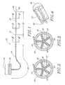
- FIG. 4is a perspective view of the end portion and support beam of the catheter of FIG. 1 , illustrating a cross-section taken along line 4 - 4 of FIG. 1 ;
- FIG. 5is a side view of a catheter having features and advantages in accordance with a second embodiment of the present invention.
- FIG. 6is a cross-sectional view of the infusion section of the catheter of FIG. 5 taken along line 6 - 6 of FIG. 5 ;
- FIG. 7is a cross-sectional view of a catheter having features and advantages in accordance with a third embodiment of the present invention.
- FIG. 8is a side view of a catheter having features and advantages in accordance with a fourth embodiment of the present invention.
- FIG. 9is a side view of a catheter having features and advantages in accordance with a fifth embodiment of the present invention.
- FIG. 10Ais a cross-sectional view of the catheter of FIG. 9 , illustrating an unstretched state of the spring;
- FIG. 10Ais a cross-sectional view of the catheter of FIG. 9 , illustrating a stretched state of the spring
- FIG. 11is a cross-sectional view of a catheter having features and advantages in accordance with a sixth embodiment of the present invention.
- FIG. 12is a side view of a catheter having features and advantages in accordance with the sixth embodiment of the present invention.
- FIG. 13is a longitudinal cross-sectional view of a catheter having features and advantages in accordance with the seventh embodiment of the present invention.
- FIGS. 14-16are longitudinal cross-sectional views of catheters similar to that of FIG. 13 , illustrating alternative attachments between the internal porous member and the tube;
- FIG. 17is a transverse cross-sectional view of a catheter according to FIGS. 13-16 , wherein the internal porous member is concentric with the outer tube;
- FIG. 18is a transverse cross-sectional view of a catheter according to FIGS. 13-16 , wherein the internal porous member is not concentric with the outer tube;
- FIG. 19is a schematic illustration of a catheter of the present invention used in conjunction with an air eliminating filter
- FIG. 20is a side view of a catheter having features and advantages in accordance with the eighth embodiment of the present invention.
- FIG. 21is a side view of a catheter having features and advantages in accordance with the ninth embodiment of the present invention.
- FIG. 22is a schematic illustration of the use of a catheter of the present invention for treating a blood clot.
- FIGS. 1-4illustrate an infusion catheter 20 according to one embodiment of the present invention.
- Catheter 20preferably includes a flexible support 22 ( FIGS. 2-4 ), a non-porous membrane 24 , and a porous membrane 26 .
- the membranes 24 and 26are wrapped around the support 22 to form a plurality of axial lumens between the inner surfaces of the membranes 24 and 26 and the surface of the support 22 , as described in greater detail below.
- the non-porous membrane 24defines a non-infusing section 28 of the catheter 20 , and preferably covers the support 22 from the proximal end thereof to a point 30 , shown in FIG. 1 .
- the porous membrane 26defines an infusion section 32 of catheter 20 , and preferably covers the support 22 from the point 30 to the distal end of support 22 .
- the catheter 20may be configured without a non-porous membrane 24 .
- the porous membrane 26covers the entire length of the support 22 , so that the entire length of the support 22 corresponds to the infusion section of the catheter 20 .
- the infusion sectioncan have any desired length.
- the proximal end of the catheter 20may be connected to a fluid supply 34 containing a fluid 36 such as a liquid medication.
- the distal end of catheter 20may include a cap 48 ( FIG. 4 ) defining the endpoint of the axial lumens within the catheter 20 .
- the catheter 20is inserted into an anatomical system, such as a human body, to deliver fluid medication directly to a wound area within the anatomical system.
- the catheter 20is designed to deliver medication throughout a generally linear segment of the wound area, corresponding to the infusion section 32 of the catheter 20 .
- the catheteris preferably inserted so that the infusion section 32 is positioned within the wound area.
- a physician or nursemay insert the catheter 20 with the aid of an axial guide wire 46 positioned within an axial guide wire lumen 44 of the catheter. Once the catheter is positioned as desired, the guide wire 46 is simply pulled back out through the proximal end of the catheter 20 .
- the catheter 20may be provided without a guide wire or a guide wire lumen.
- FIGS. 2 and 3illustrate a preferred configuration of the support 22 .
- the surface of the support 22includes interruptions such as a plurality of ribs 40 as shown in the figures.
- the interruptionsare configured so that when the membranes 24 and 26 are wrapped around the support 22 , the membranes form a portion of the walls of a plurality of axial lumens 38 within which the fluid 36 may flow.
- a plurality of ribs 40extend radially from a common axial center portion 42 of the support 22 .
- the ribs 40also extend longitudinally along a length of the support 22 , and preferably along the entire length thereof. In the non-infusing section 28 , shown in FIG.
- the non-porous membrane 24is preferably tightly wrapped around the outer edges of the ribs 40 .
- the axial lumens 38are formed between the inner surface of the non-porous membrane 24 and the outer surface of support 22 .
- the porous membrane 26is preferably tightly wrapped around the outer edges of the ribs 40 , so that the axial lumens 38 are formed between the inner surface of porous membrane 26 and the outer surface of support 22 .
- the porous membrane 26may be wrapped around the entire length of the support 20 , thus replacing the non-porous membrane 24 .
- the entire length of the support 22corresponds to the infusion section 32 .
- the support 22may extend only within the infusion section 32 , and a tube may be provided extending from the fluid supply 34 to the proximal end of the support 22 .
- the tubereplaces the non-porous membrane 24 and the portion of the support 22 extending within the non-infusing section 28 of the preferred embodiment. In other words, the tube defines the non-infusing section 28 .
- the number of ribs 40equals the number of axial lumens 38 .
- five ribs 40 and axial lumens 38are shown in FIGS. 2 and 3 , any suitable number of ribs 40 and lumens 38 may be provided, giving due consideration to the goals of providing a plurality of lumens within the catheter 20 , maintaining flexibility, and, if desired, maintaining the fluid independence of the lumens.
- the membranes 24 and 26are preferably glued along the outer edges of the ribs 40 , utilizing any suitable glue, such as a medical grade glue or epoxy. This prevents the membranes 24 and 26 from slipping, which might occur as the catheter is inserted or removed from the anatomy. More preferably, the membranes are glued along the entire length of the outer edges of each of the ribs 40 . Alternatively, the membrane may be wrapped around the support and not secured to the support by a foreign substance. The membrane and support may also be secured to each other by other means known to those of skill in the art. This maintains the fluid independence of the lumens 38 . If desired, an axial guide wire lumen 44 may be provided within the axial central portion 42 of the support 22 . The guide wire lumen 44 is adapted to receive a guide wire 46 which may be used to aid in the insertion of the catheter 20 into the anatomy, as described above and as will be easily understood by those of skill in the art.
- the catheter 20preferably includes an end portion or cap 48 secured to the distal end of support 22 .
- End portion 48may be formed integrally with the support 22 or may be adhesively bonded thereto.
- the proximal end of end portion 48is circular and has a diameter such that the outer surface of the proximal end of end portion 48 is aligned with the outer edges of the ribs 40 of the support 22 , as shown.
- the porous membrane 26is wrapped around the proximal end of the end portion 48 .
- the membrane 26is preferably glued to the end portion 48 so that fluid 36 within the lumens 38 is prevented from exiting the catheter 20 without passing through the walls of the membrane 26 .
- End portion 48blocks axial fluid flow through the distal end of catheter 20 .
- end portion 48may optionally be formed from a porous material to permit some axial dispensation of fluid from the distal end of the catheter 20 , if desired.
- the distal end of end portion 48is preferably dome-shaped, as shown, to permit the catheter 20 to more easily be inserted into an anatomical region.
- the support 22can be formed from a variety of materials, giving due consideration to the goals of flexibility, light-weight, strength, smoothness, and non-reactivity to anatomical systems, i.e., safety. Suitable materials for the support 22 include nylon, polyamide, teflon, and other materials known to those skilled in the art.
- the porous membrane 26is preferably a sponge-like or foam-like material or a hollow fiber. The membrane 26 may be formed from a variety of suitable materials, giving due consideration to the goals of being flexible and non-reactive to anatomical systems.
- the membrane 26preferably has a porosity resulting in substantially uniform dispensation of fluid along the surface area of the infusion section 32 of the catheter 20 , and has an average pore size sufficiently small to limit the flow of bacteria through the membrane walls.
- Some suitable materials for the membrane 26are polyethylene, polysulfone, polyethersulfone, polypropylene, polyvinylidene difluoride, polycarbonate, nylon, or high density polyethylene. These materials are advantageously biocompatible.
- the porous membrane 26may filter out unwanted bacteria from the fluid medication as it passes through the membrane 26 . It is known that the smallest bacteria cannot pass through a pore any smaller than 0.23 microns.
- the average pore size, or pore diameter, of the porous membrane 26may be less than 0.23 microns to prevent bacteria from traversing the membrane 26 .
- the average pore size, or pore diameter, of the membrane 26is preferably within the range of about 0.1 to 1.2 microns, more preferably within the range of about 0.3 to 1 micron, and even more preferably about 0.8 microns.
- the proximal end of catheter 20may be connected to a fluid supply 34 .
- the catheter 20may be configured so that each axial lumen 38 is fluidly independent. In other words, the lumens 38 would not fluidly communicate with one another.
- the catheter 20may be connected to a single fluid supply 34 , so that the fluid 36 flows within each of the lumens 38 .
- the catheter 20may be connected to a plurality of separate fluid supplies so that several different fluids may separately flow within the lumens 38 .
- each lumen 38may be connected to a separate fluid supply so that the total number of different fluids that may be delivered to the anatomy is equal to the number of lumens 38 .
- the fluid lumensneed not be fluidly independent.
- the membrane 26may not be secured to the support 22 along the entire length of the support 22 , thus permitting fluid 36 to migrate between lumens 38 .
- the catheter 20delivers fluid directly to the area of the anatomy that is adjacent to the infusion section 32 .
- the fluid 36 from the fluid source 34is introduced into the axial lumens 38 at the proximal end of the catheter 20 .
- the fluid 36initially flows through the non-infusing section 28 .
- the fluid 36first reaches the infusion section 32 , it soaks into the porous membrane 26 .
- As more fluid 36 enters the infusion section 32it diffuses longitudinally within the walls of the membrane 26 until the entire membrane 26 and infusion section 32 are saturated with fluid. At this point the fluid 36 begins to pass through the membrane 26 , thereby exiting the catheter 20 and entering the anatomy.
- the fluid 36advantageously passes through the entire surface area of the porous membrane 26 at a substantially uniform rate, due to the characteristics of the membrane 26 .
- the fluidis delivered at a substantially equal rate throughout a generally linear segment of the wound area of the anatomy. Furthermore, this advantage is obtained for both low and high pressure fluid delivery.
- FIGS. 5 and 6illustrate a catheter 50 according to an alternative embodiment of the present invention.
- the catheter 50includes an elongated outer tube 52 and an inner elongated tubular porous membrane 54 .
- the tubular membrane 54is preferably concentrically enclosed within the outer tube 52 . More preferably, the tube 52 tightly surrounds and supports the tubular membrane 54 so that a relatively tight fit is achieved between the inner dimensions of tube 52 and the outer dimensions of membrane 54 .
- a plurality of fluid exit holes 56are provided within the tube 52 , preferably throughout the entire circumference thereof. The portion of tube 52 that includes the exit holes 56 defines the infusion section of catheter 50 .
- the tubular membrane 54need only be provided along the length of the infusion section, but could be longer.
- axial exit holesmay be provided within the distal tip 58 of the tube 52 .
- a guide wire and/or guide wire lumenmay be provided to aid in the insertion of the catheter 50 into the anatomy, as will be understood by those skilled in the art.
- the tube 52may be formed from any of a variety of suitable materials, such as nylon, polyimide, teflon and other materials known to those skilled in the art, giving due consideration to the goals of non-reactivity to anatomical systems, flexibility, light-weight, strength, smoothness, and safety.
- the tube 52is preferably a 20 gauge catheter tube, having inside and outside diameters of 0.019 inches and 0.031 inches, respectively.
- the exit holes 56 of tube 52are preferably about 0.015 inches in diameter and provided at equally spaced axial positions along the tube 52 .
- the holes 56are preferably arranged so that every hole is angularly displaced about 120 relative to the longitudinal axis of the tube 52 , from the angular location of the previous hole.
- the axial separation between adjacent exit holes 56is preferably within the range of about 0.125 to 0.25 inches, and more preferably about 3/16 inch.
- the infusion sectioncan have any desirable length. This configuration results in a thorough, uniform delivery of fluid throughout a generally linear segment of the wound area.
- the exit holes 56may be provided in any of a variety of alternative arrangements.
- the tubular porous membrane 54is preferably a sponge-like or foam-like material or a hollow fiber.
- the tubular membrane 54may have an average pore size, or pore diameter, less than 0.23 microns to filter bacteria.
- the pore diameteris preferably within the range of about 0.1 to 1.2 microns, more preferably within the range of about 0.3 to 1 micron, and even more preferably about 0.8 microns.
- the tubular membrane 54may be formed from any of a variety of suitable materials, giving due consideration to the goals of non-reactivity to anatomical systems, maintaining flexibility, fitting within the size constraints of the tube 52 , and having a porosity resulting in the substantially uniform dispensation of fluid through all of the exit holes 56 in tube 52 .
- the membrane 54is polyethylene, polysulfone, polyethersulfone, polypropylene, polyvinylidene difluoride, polycarbonate, nylon, or high density polyethylene. Preferable inside and outside diameters of the tubular membrane 54 are 0.010 inches and 0.018 inches, respectively. In the event that a guide wire 46 is provided, the guide wire may be a stainless steel wire about 0.005 inches in diameter.
- the tube 52may be secured to the membrane 54 by epoxy or other means known to those skilled in the art. Alternatively, the membrane 54 may contact the tube 52 with an interference fit and not use other materials to secure the membrane 54 in the tube 52 .
- the catheter 50delivers fluid to the region of an anatomical system adjacent to the infusion section of catheter 50 .
- the fluidflows into the infusion section, it initially soaks into the tubular porous membrane 54 .
- the fluiddiffuses longitudinally within the walls of the tubular member 54 .
- the membrane 54 and the tubular space thereinare saturated, the fluid passes through the membrane 54 and exits the catheter 50 by flowing through the exit holes 56 of the tube 52 .
- the fluidadvantageously passes through the membrane substantially uniformly throughout the surface area of the membrane 54 , resulting in a substantially uniform flow through substantially all of the exit holes 56 .
- the fluidis delivered at a substantially equal rate throughout the wound area of the anatomy. Furthermore, this advantage is obtained for both low and high pressure fluid delivery.
- FIG. 7illustrates a catheter 70 according to another embodiment of the present invention.
- Catheter 70includes a tube 72 having a plurality of exit holes 76 in side walls of the tube, and a tubular porous membrane 74 concentrically enclosing the tube 72 .
- Catheter 70operates in a similar manner to catheter 50 described above in connection with FIGS. 5 and 6 .
- fluid medicationpasses through the exit holes 76 and then begins to soak into the porous membrane 74 .
- the fluiddiffuses longitudinally within the walls of the membrane until the membrane is saturated. Thereafter, the fluid leaves the membrane walls and enters the anatomy.
- the fluidis dispensed to the anatomy at a substantially uniform rate throughout the surface area of the membrane 74 . As in the previous embodiments, this advantage is obtained for both low and high pressure fluid delivery.
- FIG. 8illustrates a catheter 60 according to another embodiment of the present invention.
- Catheter 60is better suited for relatively high flow rate delivery of fluid to a region within an anatomical system.
- Catheter 60includes a tube 62 having a plurality of exit holes 64 of increasing size. In particular, the more distal exit holes are larger in diameter than the more proximal exit holes.
- the position of the exit holes 64 on the tube 62defines the length of the infusion section of the catheter 60 .
- the infusion sectioncan have any desired length.
- the proximal end of catheter 60is connected to a fluid supply, and a guide wire and/or guide wire lumen may also be provided for aiding in the insertion of catheter 60 into the anatomy.
- exit holes nearer to the distal end of a catheter tubegenerally have increased flow resistance compared to exit holes nearer to the proximal end of the tube.
- the fluid flowing through the more distal holesexperiences a greater pressure drop. Consequently, there is generally a greater flow rate of fluid through the more proximal holes, resulting in non-uniform fluid delivery.
- catheter 60advantageously provides substantially uniform fluid delivery through substantially all of the exit holes 64 , under relatively high flow rate conditions. This is because the larger size of the more distal holes compensates for their increased flow resistance and pressure drop.
- the holes 64are provided in a gradually increasing size which results in substantially uniform fluid delivery.
- the exit holes 64may be sized so that they combine to form a flow-restricting orifice, as described below in connection with the embodiment of FIG. 12 .
- catheter 60is advantageously simple and easy to manufacture. All that is required is to drill a plurality of exit holes 64 in the tube 62 . Furthermore, catheter 60 can sustain greater bending than prior art catheters while maintaining operability. In contrast to prior art catheters, such as the Wang catheter, if the tube 62 is bent somewhat, it will still deliver fluid relatively uniformly. This is because the tube 62 has a single lumen with a relatively large cross-section. When the tube 62 is somewhat bent, fluid flowing within the lumen is less likely to experience blockage and a consequent pressure change which might lead to non-uniform fluid dispensation.
- the tube 62 of catheter 60may be formed from any of a wide variety of materials, giving due consideration to the goals of non-reactivity to anatomical systems, flexibility, light-weight, strength, smoothness, and safety. Suitable materials include nylon, polyimide, teflon, and other materials known to those skilled in the art.
- the infusion sectioncan have any desired length but is preferably about 0.5 to 20 inches long, and more preferably about 10 inches long.
- the diameter of the exit holes 64preferably ranges from about 0.0002 inches at the proximal end of the infusion section to about 0.01 inches at the distal end thereof. The largest, i.e., most distal, exit hole 64 is preferably about 0.25 inches from the distal end of the tube 62 .
- the axial separation between adjacent holes 64is within the range of about 0.125 to 0.25 inches, and more preferably about 3/16 inch.
- the holes 64may be provided so that adjacent holes are angularly displaced by about 120 as in the embodiment of FIG. 5 .
- the tube 62may be undesirably weakened.
- FIGS. 9 , 10 A, and 10 Billustrate a catheter 80 according to another embodiment of the present invention.
- the catheter 80comprises a tube 82 , a “weeping” tubular coil spring 84 , and a stop 86 .
- the proximal end of the spring 84is attached to the distal end of the tube 82 so that the tube and spring each define a portion of a central lumen.
- a preferably dome-shaped stop 86is attached to and closes the distal end of the spring 84 .
- the portion of the spring 84 that is distal to the tube 82comprises the infusion section of the catheter 80 . In an unstretched state, shown in FIG.
- the spring 84has adjacent coils in contact with one another so that fluid within the spring and below a threshold dispensation pressure is prevented from exiting the lumen by flowing radially between the coils.
- the spring 84has the property of stretching longitudinally, as shown in FIG. 10B , when the fluid pressure is greater than or equal to the threshold dispensation pressure of the spring, thereby permitting the fluid to be dispensed from the lumen by “weeping,” i.e., leaking radially outward between the coils.
- the springmay stretch radially without elongating to permit fluid to weep through the coils of the spring.
- the springmay stretch both longitudinally and radially to permit weeping, as will be understood by those of skill in the art.
- the fluid between the coils of the springis dispensed substantially uniformly throughout the length and circumference of the portion of the spring that is distal to the tube 82 , i.e., the infusion section.
- the catheter 80can be used for both high or low flow rate fluid delivery.
- the catheter 80is inserted into an anatomical region so that the spring 84 is in a region to which fluid medication is desired to be delivered.
- the springis initially in an unstretched state, as shown in FIG. 10A .
- the fluidis introduced into a proximal end of the tube 82 of the catheter 80 and flows into and through the spring 84 until it reaches the stop 86 .
- the fluidbuilds inside of the spring 84 .
- the spring 84is filled with fluid, the fluid pressure rises more quickly. The fluid imparts a force directed radially outward onto the spring coils. As the pressure builds, the outward force becomes larger.
- the outward forcecauses the spring coils to separate slightly so that the spring stretches longitudinally, as shown in FIG. 10B .
- the coilsmay separate radially, as discussed above.
- the fluidthen flows through the separated coils to be dispensed from the catheter 80 .
- the dispensationis advantageously uniform throughout the infusion section of the catheter 80 .
- the spring 84remains stretched to continually dispense fluid to the desired region within the anatomy. If the fluid introduction temporarily ceases, the fluid pressure within the spring 84 may fall below the threshold dispensation pressure. If so, the spring will compress so that the coils are once again adjacent and the fluid is no longer dispensed.
- Suitable spring typesare 316L or 402L, which can be readily purchased.
- the spring 84has about 200 coils per inch along its length. In this configuration, the spring can advantageously sustain a high degree of bending without leaking fluid from within, and only a severe bend will cause adjacent coils to separate. Thus, the spring 84 may be flexed considerably within an anatomical region without causing fluid to leak and therefore be dispensed to only one region within the anatomy.
- the spring 84can have any desired length to define the length of the infusion section of the catheter 80 .
- the springmay be formed from a variety of materials, giving due consideration to the goals of strength, flexibility, and safety. A preferred material is stainless steel.
- the inside and outside diameters of the springare about 0.02 inches and 0.03 inches, respectively, and the spring wire has a diameter of about 0.005 inches.
- the proximal end of the spring 84is preferably concentrically enclosed within the distal end of the tube 82 .
- the springcan be glued to the inside wall of the tube 82 using, for example, a U.V. adhesive, a potting material, or other bonding materials.
- the springcan be soldered within the tube 82 or be fitted with a proximal plug and tightly plugged into the tube 82 .
- the tube 82 and stop 86can be formed from any of a variety of materials, giving due consideration to the goals of flexibility, light-weight, strength, smoothness, and safety. Suitable materials include nylon, polyimide, teflon, and other materials known to those skilled in the art.
- FIG. 11illustrates a catheter 90 according to another embodiment of the present invention.
- the catheter 90comprises a distally closed tube 92 and a “weeping” tubular coil spring 94 concentrically enclosed within the tube 92 so that a lumen is defined within the tube and spring.
- a plurality of exit holes 96are provided along a length of the tube 92 , in the side wall thereof.
- the length of the tube 92 including such exit holes 96defines an infusion section of the catheter 90 .
- the exit holes 96are preferably provided throughout the walls of the infusion section.
- the infusion sectioncan have any desired length.
- the axial spacing between adjacent holes 96is within the range of about 0.125 to 0.25 inches, and more preferably about 3/16 inch.
- Adjacent holes 96are preferably angularly spaced apart by about 120°.
- the spring 94is preferably enclosed within the infusion section of the catheter and configured similarly to the spring 84 of the embodiment of FIGS. 9 , 10 A and 10 B.
- the spring 94is preferably longer than the infusion portion and positioned so that all of the exit holes 96 are adjacent to the spring 94 . In this configuration, the fluid is prevented from exiting the lumen without flowing between the spring coils.
- a stopis preferably attached to the tube to close the distal end thereof.
- the tube 92may be formed with a closed distal end.
- the catheter 90can be used for high or low flow rate fluid delivery.
- the catheter 90is inserted into an anatomical region so that the infusion section is in a region to which fluid medication is desired to be delivered.
- the fluidis introduced into a proximal end of the tube 92 of the catheter 90 and flows through the spring 94 until it reaches the closed distal end of the tube 92 .
- the fluidbuilds inside of the spring 94 .
- the spring 94becomes filled with fluid, the fluid pressure rises, and the fluid weeps through the spring coils as described above in connection with the embodiment of FIGS. 9 , 10 A, and 10 B.
- the fluidflows through the spring coils substantially uniformly throughout the length and circumference of the spring 94 .
- the fluidthen exits the tube 92 by flowing through the exit holes 96 of the infusion section.
- the exit holesare preferably equal in size so that the fluid flows at a substantially equal rate through the exit holes, advantageously resulting in a generally uniform distribution of fluid throughout a desired region of the anatomy.
- the spring 94As fluid is continually introduced into the catheter 90 , the spring 94 remains stretched to continually dispense fluid from the catheter. If the fluid introduction ceases temporarily, the fluid pressure within the spring 94 may fall below the threshold dispensation pressure. If so, the spring may compress so that the coils are once again adjacent and the fluid is no longer dispensed.
- the spring 94 and tube 92are in contact along the entire length of the spring, so that the fluid weeping through the spring is forced to flow through the holes 96 of the infusion section.
- one end of the spring 94is attached to the inside walls of the tube 92 , permitting the other end of the spring to be displaced as the spring stretches.
- the springcan be glued to the tube 92 with, for example, a U.V. adhesive, potting material, or other bonding materials.
- an end of the springcan be soldered onto the inner walls of the tube 92 .
- the tube 92can be formed from any suitable material.
- the inside walls of the tube 92are preferably smooth so that the spring can more freely stretch and compress.
- FIG. 12illustrates a catheter 100 according to another embodiment of the present invention.
- the catheter 100comprises a distally closed tube 102 having a plurality of exit holes 104 in side walls of the tube 102 .
- the portion of the tube 102 having exit holes 104defines an infusion section of the catheter 100 .
- the exit holes 104are sized to have a combined area of opening that is smaller than the area of any other flow-restricting cross-section or orifice of the catheter.
- the exit holes 104are the flow-restrictor of the catheter 100 .
- the catheteradvantageously dispenses fluid through substantially all of the exit holes 104 .
- a fluid introduced into a proximal end of the tube 102flows through the tube until it reaches the closed distal end thereof.
- the fluidbuilds within the infusion portion of the catheter.
- the fluidis substantially prevented from flowing through the holes 104 , due to their small size.
- the infusion portion of the catheterbecomes filled with fluid.
- the fluid pressurebegins to build. At some point the pressure becomes sufficiently high to force the fluid through the exit holes 104 .
- the fluidflows through substantially all of the exit holes 104 .
- the exit holes 104are all equal in size so that the fluid is dispensed at a substantially equal rate through substantially all of the holes.
- the holes 104are preferably laser drilled to achieve a very small hole diameter.
- a preferred diameter of the exit holes 104is about 0.0002 inches, or about 5 microns.
- Numerous exit holes 104may be provided within the tube 102 .
- the holesare advantageously provided throughout the circumference of the infusion portion of the catheter 100 , to more uniformly deliver the fluid throughout an anatomical region.
- a preferred axial spacing between adjacent holes 104is within the range of about 0.125 to 0.25 inches, and more preferably about 3/16 inch.
- the catheter 100can be used for high or low flow rate fluid delivery.
- the tube 102can be formed from any of a variety of materials known to those skilled in the art and discussed previously.
- FIG. 13illustrates a catheter 200 according to another embodiment of the present invention.
- Catheter 200includes a distally closed tube 202 having a plurality of exit holes 204 therein along an infusion section of the catheter, as in the above-described embodiments.
- the holes 204are desirably provided throughout the circumference of the tube 202 .
- an elongated member 206formed of a porous material.
- the member 206is generally cylindrical in shape, and solid.
- the member 206is positioned within the tube 204 so that an annular space 208 is formed between the outer surface of the member 206 and the inner surface of the tube 202 .
- the member 206extends from the distal end 210 of the tube 202 rearwardly to a point proximal of the infusion section of the catheter. Alternatively, the member 206 may extend along only a portion of the infusion section.
- the member 206is preferably generally concentric with the tube 202 , but non-concentric designs will achieve the advantages of the invention.
- the member 206is manufactured of a flexible material to assist with the placement of the catheter 200 in the body of a patient.
- fluid medication flowing in the tube 202saturates the porous member 206 and flows into the annular region 208 .
- the fluid in the member 206flows into the region 208 and out of the catheter 200 through the exit holes 204 .
- the fluid pressureis uniform throughout the annular region 208 , the fluid flows substantially uniformly through all of the holes 204 .
- the annular region 208may be formed from a porous material that tends to expand when saturated with liquid. If so, the member 206 preferably expands into the annular region 208 without pressing against the tube 202 . This limits the possibility of high pressure regions at the interior surface of the tube 202 , which could cause uneven exit flow of the medication within the wound site. Alternatively, the member 206 may expand and come into contact with the tube 202 , and still accomplish the goals of the present invention.
- the member 206is formed of a porous material having an average pore size preferably within the range of 0.1-50 microns, and more preferably about 0.45 microns.
- the radial width W of the annular region 208is preferably within the range of 0 to about 0.005 microns, and more preferably about 0.003 microns.
- the member 206can be formed of any of a variety of materials, giving due consideration to the goals of porosity, flexibility, strength, and durability. A preferred material is Mentek.
- the member 206can be secured within the tube 202 by the use of an adhesive.
- the adhesiveis applied at the distal end of the member 206 to form a bond with the interior surface of the distal end of the tube 202 .
- adhesiveis applied at or near the proximal end of the infusion section of the catheter 200 .
- the adhesivecan be applied to the circumference of the member 206 at any longitudinal position thereof, forming a ring-shaped bond with the interior surface of the tube 202 .
- a ring-shaped bond 214is provided just proximal of the infusion section of the catheter 200 .
- FIG. 13Other configurations are possible. For example, FIG.
- FIG. 14shows an embodiment in which the adhesive is applied to the distal end of the member 206 to form a bond 216 , and also at generally the center of the infusion section to form a ring-shaped bond 218 .
- FIG. 15shows an embodiment in which the adhesive is applied only to the distal end of the member 206 to form a bond 220 .
- FIG. 16shows an embodiment in which the adhesive is applied only to the center of the infusion section to form a ring-shaped bond 222 .
- the adhesivemay be applied in any of a variety of configurations. Thus, for example, adhesive at the distal end of the catheter (i.e., 212 , 216 , and 220 in FIGS. 13 , 14 , and 15 , respectively) is not required.
- each bondis formed with an adhesive as described below.
- the ring-shaped bond 214can be formed by pouring the adhesive in liquid form through one of the exit holes 204 when the member 206 is in the tube 202 .
- the adhesivehaving a generally high viscosity, tends to flow about the circumference of the member 206 , rather than into the body of the member.
- the adhesivethus forms a ring-shaped bond with the tube 202 , as will be understood by those of skill in the art.
- the adhesiveplugs the exit hole 204 through which it is poured. Any of a variety of different types of adhesives will be acceptable, a preferred adhesive being Loctite.
- the member 206is preferably concentric with the tube 202 .
- FIG. 17shows a cross-section of a catheter 200 in which the member 206 is concentrically enclosed within the tube 202 .
- the member 206may be positioned adjacent to the tube 202 , as shown in FIG. 18 .
- the configuration of FIG. 18may be easier to manufacture than that of FIG. 17 , since the member 206 does not have to be centered within the tube 202 .
- the member 206can be of any desired length and can extend along any desired length of the infusion section of the catheter 200 .
- the member 206does not have to extend to the distal end of the tube 202 .
- the proximal end of the member 206may be either distal or proximal to the proximal end of the infusion section.
- the cathetermay initially have air inside of the catheter tube.
- the catheter 200 shown in FIG. 13may have air inside of the porous material of the member 206 .
- the introduction of liquid medication into the catheterforces the air to flow out of the exit holes. However, this may take several hours.
- the catheteris inserted into a patient while air is inside, and liquid medication is introduced into the catheter, the patient's wound site may receive little or no medication until air is expelled from the catheter tube.
- an air filter 224can be inserted into the catheter tubing proximal the infusion section 226 of the catheter 200 . The filter 224 prevents undesirable air from entering the infusion section 226 of the catheter 200 .
- FIGS. 20 and 21illustrate catheter tubes having elongated exit holes or slots. These catheter tubes may be used in place of the catheter tubes shown and described above.
- FIG. 20shows a tube 230 having exit holes or slots 232 that are elongated in the longitudinal direction of the tube 230 .
- the slots 232are preferably provided throughout the circumference of the tube 230 , along the infusion section of the catheter. Compared to smaller exit holes, the elongated slots 232 tend to increase the flowrate of fluid exiting the catheter, by reducing the flow impedance experienced by the fluid.
- the slots 232may be oriented longitudinally on the catheter body so as not to compromise the structural integrity of the catheter 200 , as will be easily understood by those of skill in the art.
- FIG. 21shows a tube 234 having exit holes or slots 236 whose lengths increase along the length of the tube in the distal direction.
- the slots nearer to the proximal end of the infusion section of the tube 234are shorter in length than the slots nearer to the distal end of the infusion section.
- the catheter tube 234advantageously provides substantially uniform fluid delivery through substantially all of the exit slots 236 , under relatively high flow rate conditions. This is because the larger size of the more distal slots compensates for their increased flow resistance and pressure drop.
- the slots 236are provided in a gradually increasing length, which results in substantially uniform fluid delivery. Further, the elongated slots result in generally higher exit flowrates, as in the embodiment of FIG. 20 .
- an independent guide wire lumenmay be provided within or adjacent to the lumen(s) disclosed, as will be understood by those skilled in the art.
- a catheter 20(reference numeral 20 is used to identify the catheter, but any of the above-described catheters can be used) is inserted into a blood clot 240 inside of a vein or artery 242 .
- the infusion section of the catheteris within the blood clot 240 .
- Liquid medicationis preferably introduced into the proximal end of the catheter tube.
- the medicationexits the catheter 20 at a uniform rate throughout the infusion section to dissolve the clot 240 .
- any of the catheter embodiments described hereinmay be used in a variety of applications including, but not limited to, peripheral nerve blocks, intrathecal infusions, epideral infusions, intravascular infusions, intraarterial infusions and intraarticular infusions, as well as in wound site pain management.
- any of the catheters disclosed hereinmay be integral with a fluid line eminating from an infusion pump as opposed to being an independent catheter designed to be connected or secured to an infusion pump.
Landscapes
- Health & Medical Sciences (AREA)
- Life Sciences & Earth Sciences (AREA)
- General Health & Medical Sciences (AREA)
- Public Health (AREA)
- Engineering & Computer Science (AREA)
- Anesthesiology (AREA)
- Biomedical Technology (AREA)
- Heart & Thoracic Surgery (AREA)
- Hematology (AREA)
- Animal Behavior & Ethology (AREA)
- Biophysics (AREA)
- Pulmonology (AREA)
- Veterinary Medicine (AREA)
- Media Introduction/Drainage Providing Device (AREA)
- Infusion, Injection, And Reservoir Apparatuses (AREA)
- Materials For Medical Uses (AREA)
- Acyclic And Carbocyclic Compounds In Medicinal Compositions (AREA)
- Radiation-Therapy Devices (AREA)
- Endoscopes (AREA)
- Ultra Sonic Daignosis Equipment (AREA)
Abstract
Description
Claims (20)
Priority Applications (1)
| Application Number | Priority Date | Filing Date | Title |
|---|---|---|---|
| US10/031,913US7780638B1 (en) | 1999-07-19 | 2000-07-19 | Catheter for uniform delivery of medication |
Applications Claiming Priority (4)
| Application Number | Priority Date | Filing Date | Title |
|---|---|---|---|
| US09/363,228US6350253B1 (en) | 1999-07-19 | 1999-07-19 | Catheter for uniform delivery of medication |
| US09/363228 | 1999-07-19 | ||
| PCT/US2000/019746WO2001005210A2 (en) | 1999-07-19 | 2000-07-19 | Catheter for uniform delivery of medication |
| US10/031,913US7780638B1 (en) | 1999-07-19 | 2000-07-19 | Catheter for uniform delivery of medication |
Related Parent Applications (2)
| Application Number | Title | Priority Date | Filing Date |
|---|---|---|---|
| US09/363,228Continuation-In-PartUS6350253B1 (en) | 1999-07-19 | 1999-07-19 | Catheter for uniform delivery of medication |
| PCT/US2000/019746A-371-Of-InternationalWO2001005210A2 (en) | 1999-07-19 | 2000-07-19 | Catheter for uniform delivery of medication |
Related Child Applications (5)
| Application Number | Title | Priority Date | Filing Date |
|---|---|---|---|
| US10/104,171ContinuationUS7004923B2 (en) | 1999-07-19 | 2002-03-21 | Catheter for uniform delivery of medication |
| US10/436,457Continuation-In-PartUS7452353B2 (en) | 1999-07-19 | 2003-05-12 | Catheter for uniform delivery of medication |
| US10/435,946Continuation-In-PartUS7510550B2 (en) | 1999-07-19 | 2003-05-12 | Catheter for uniform delivery of medication |
| US10/435,946ContinuationUS7510550B2 (en) | 1999-07-19 | 2003-05-12 | Catheter for uniform delivery of medication |
| US10/828,923ContinuationUS7569045B2 (en) | 1999-07-19 | 2004-04-21 | Catheter for uniform delivery of medication |
Publications (1)
| Publication Number | Publication Date |
|---|---|
| US7780638B1true US7780638B1 (en) | 2010-08-24 |
Family
ID=23429364
Family Applications (11)
| Application Number | Title | Priority Date | Filing Date |
|---|---|---|---|
| US09/363,228Expired - LifetimeUS6350253B1 (en) | 1999-07-19 | 1999-07-19 | Catheter for uniform delivery of medication |
| US10/031,913Expired - Fee RelatedUS7780638B1 (en) | 1999-07-19 | 2000-07-19 | Catheter for uniform delivery of medication |
| US09/815,888Expired - LifetimeUS6626885B2 (en) | 1999-07-19 | 2001-03-23 | Method of fluid delivery and catheters for use with same |
| US10/085,169AbandonedUS20020082547A1 (en) | 1999-07-19 | 2002-02-25 | Catheter for uniform delivery of medication |
| US10/118,535Expired - Fee RelatedUS7527609B2 (en) | 1999-07-19 | 2002-04-08 | Catheter for uniform delivery of medication |
| US10/420,133Expired - Fee RelatedUS8043465B2 (en) | 1999-07-19 | 2003-04-18 | Catheter for uniform delivery of medication |
| US10/675,589Expired - LifetimeUS7465291B2 (en) | 1999-07-19 | 2003-09-30 | Method of fluid delivery and catheters for use with same |
| US11/364,767Expired - Fee RelatedUS7438711B2 (en) | 1999-07-19 | 2006-02-28 | Catheter for uniform delivery of medication |
| US12/335,473Expired - Fee RelatedUS7959623B2 (en) | 1999-07-19 | 2008-12-15 | Method of fluid delivery and catheters for use with same |
| US13/074,375Expired - Fee RelatedUS8328771B2 (en) | 1999-07-19 | 2011-03-29 | Method for fluid delivery and catheters for use with same |
| US13/238,497Expired - LifetimeUS9084870B2 (en) | 1999-07-19 | 2011-09-21 | Catheter for uniform delivery of medication |
Family Applications Before (1)
| Application Number | Title | Priority Date | Filing Date |
|---|---|---|---|
| US09/363,228Expired - LifetimeUS6350253B1 (en) | 1999-07-19 | 1999-07-19 | Catheter for uniform delivery of medication |
Family Applications After (9)
| Application Number | Title | Priority Date | Filing Date |
|---|---|---|---|
| US09/815,888Expired - LifetimeUS6626885B2 (en) | 1999-07-19 | 2001-03-23 | Method of fluid delivery and catheters for use with same |
| US10/085,169AbandonedUS20020082547A1 (en) | 1999-07-19 | 2002-02-25 | Catheter for uniform delivery of medication |
| US10/118,535Expired - Fee RelatedUS7527609B2 (en) | 1999-07-19 | 2002-04-08 | Catheter for uniform delivery of medication |
| US10/420,133Expired - Fee RelatedUS8043465B2 (en) | 1999-07-19 | 2003-04-18 | Catheter for uniform delivery of medication |
| US10/675,589Expired - LifetimeUS7465291B2 (en) | 1999-07-19 | 2003-09-30 | Method of fluid delivery and catheters for use with same |
| US11/364,767Expired - Fee RelatedUS7438711B2 (en) | 1999-07-19 | 2006-02-28 | Catheter for uniform delivery of medication |
| US12/335,473Expired - Fee RelatedUS7959623B2 (en) | 1999-07-19 | 2008-12-15 | Method of fluid delivery and catheters for use with same |
| US13/074,375Expired - Fee RelatedUS8328771B2 (en) | 1999-07-19 | 2011-03-29 | Method for fluid delivery and catheters for use with same |
| US13/238,497Expired - LifetimeUS9084870B2 (en) | 1999-07-19 | 2011-09-21 | Catheter for uniform delivery of medication |
Country Status (25)
| Country | Link |
|---|---|
| US (11) | US6350253B1 (en) |
| EP (2) | EP1202768B1 (en) |
| JP (3) | JP4387626B2 (en) |
| KR (3) | KR20020035104A (en) |
| CN (3) | CN1951517B (en) |
| AT (1) | ATE449626T1 (en) |
| AU (3) | AU777560B2 (en) |
| BR (1) | BR0012686B1 (en) |
| CA (2) | CA2375930C (en) |
| CZ (1) | CZ2002215A3 (en) |
| DE (1) | DE60043389D1 (en) |
| DK (1) | DK2135633T3 (en) |
| ES (1) | ES2450369T3 (en) |
| HK (1) | HK1046507B (en) |
| HU (1) | HU226403B1 (en) |
| IL (1) | IL147713A0 (en) |
| MX (1) | MXPA02000637A (en) |
| NO (1) | NO20020284L (en) |
| NZ (2) | NZ516785A (en) |
| PL (2) | PL203349B1 (en) |
| PT (1) | PT2135633E (en) |
| RU (1) | RU2303468C2 (en) |
| TR (2) | TR200200373T2 (en) |
| UA (1) | UA74552C2 (en) |
| WO (1) | WO2001005210A2 (en) |
Cited By (12)
| Publication number | Priority date | Publication date | Assignee | Title |
|---|---|---|---|---|
| US20090254062A1 (en)* | 2008-04-03 | 2009-10-08 | Mcglothlin Mark W | Infusion catheters with slit valves and of simplified construction |
| US20120289895A1 (en)* | 2011-03-28 | 2012-11-15 | Achilleas Tsoukalis | Fluids Exchanging System for Medical Use |
| USD679804S1 (en) | 2011-09-22 | 2013-04-09 | Vital 5, Llc | Catheter |
| WO2015044808A1 (en) | 2013-09-26 | 2015-04-02 | Avent, Inc. | Catheter-positioning slide cover clamp assembly |
| WO2015102934A1 (en) | 2013-12-30 | 2015-07-09 | Avent, Inc. | Catheter site insertion plug |
| US9265913B2 (en) | 2010-09-22 | 2016-02-23 | Vital 5, Llc | Catheter assembly |
| US9402973B2 (en) | 2007-07-06 | 2016-08-02 | Vital 5, Llc | Constrained fluid delivery device |
| US20160256634A1 (en)* | 2014-04-14 | 2016-09-08 | Masami Watanabe | Apparatus and system for controlling permeation and diffusion of solute and/or solvent locally |
| US9446224B2 (en) | 2010-09-22 | 2016-09-20 | Vital 5, L.L.C. | Barrier catheter |
| US9821141B2 (en) | 2012-07-26 | 2017-11-21 | Twin Star Medical, Inc. | Macroporous catheter |
| US20190111233A1 (en)* | 2017-10-18 | 2019-04-18 | Biosense Webster (Israel) Ltd. | High-volume manufacturing of catheters comprising electrodes having low impedance at low frequency |
| US10293105B2 (en) | 2005-09-02 | 2019-05-21 | Irras Ab | Fluid exchange catheter system |
Families Citing this family (295)
| Publication number | Priority date | Publication date | Assignee | Title |
|---|---|---|---|---|
| US8177762B2 (en) | 1998-12-07 | 2012-05-15 | C. R. Bard, Inc. | Septum including at least one identifiable feature, access ports including same, and related methods |
| US7547302B2 (en)* | 1999-07-19 | 2009-06-16 | I-Flow Corporation | Anti-microbial catheter |
| US6350253B1 (en) | 1999-07-19 | 2002-02-26 | I-Flow Corporation | Catheter for uniform delivery of medication |
| US7510550B2 (en)* | 1999-07-19 | 2009-03-31 | I-Flow Corporation | Catheter for uniform delivery of medication |
| US7004923B2 (en)* | 1999-07-19 | 2006-02-28 | I-Flow Corporation | Catheter for uniform delivery of medication |
| US7452353B2 (en)* | 1999-07-19 | 2008-11-18 | I-Flow Corporation | Catheter for uniform delivery of medication |
| US6241710B1 (en)* | 1999-12-20 | 2001-06-05 | Tricardia Llc | Hypodermic needle with weeping tip and method of use |
| US7805188B2 (en)* | 2000-03-24 | 2010-09-28 | Micor, Inc. | Anesthesia conduction catheter for delivery of electrical stimulus |
| WO2001070322A1 (en)* | 2000-03-24 | 2001-09-27 | Stephen Brushey | Anesthesia conduction catheter |
| US6475184B1 (en) | 2000-06-14 | 2002-11-05 | Scimed Life Systems, Inc. | Catheter shaft |
| US8979801B2 (en)* | 2001-01-17 | 2015-03-17 | Medtronic Vascular, Inc. | Microcatheter devices and methods for targeted substance delivery |
| US6602241B2 (en)* | 2001-01-17 | 2003-08-05 | Transvascular, Inc. | Methods and apparatus for acute or chronic delivery of substances or apparatus to extravascular treatment sites |
| US7357794B2 (en) | 2002-01-17 | 2008-04-15 | Medtronic Vascular, Inc. | Devices, systems and methods for acute or chronic delivery of substances or apparatus to extravascular treatment sites |
| US6511457B2 (en)* | 2001-05-04 | 2003-01-28 | Garey Thompson | Airless syringe |
| DE20110121U1 (en)* | 2001-06-19 | 2002-12-05 | B. Braun Melsungen Ag, 34212 Melsungen | catheter |
| US6974448B2 (en)* | 2001-08-30 | 2005-12-13 | Medtronic, Inc. | Method for convection enhanced delivery catheter to treat brain and other tumors |
| US6893429B2 (en)* | 2001-08-30 | 2005-05-17 | Medtronic, Inc. | Convection enhanced delivery catheter to treat brain and other tumors |
| US6755813B2 (en)* | 2001-11-20 | 2004-06-29 | Cleveland Clinic Foundation | Apparatus and method for performing thrombolysis |
| FR2835436B1 (en)* | 2002-02-07 | 2004-11-26 | Georges Boussignac | INSTRUMENTATION FOR ANALGESIA, ESPECIALLY PERIDURAL |
| US7815596B2 (en) | 2002-02-28 | 2010-10-19 | Cordis Corporation | Localized fluid delivery having a porous applicator and methods for using the same |
| US9694166B2 (en) | 2002-03-26 | 2017-07-04 | Medtronics Ps Medical, Inc. | Method of draining cerebrospinal fluid |
| US20030216710A1 (en)* | 2002-03-26 | 2003-11-20 | Hurt Robert F. | Catheter |
| US20030191453A1 (en)* | 2002-04-03 | 2003-10-09 | Velez Omar E. | Catheter assembly |
| AU2003223672A1 (en)* | 2002-04-17 | 2003-11-03 | Tyco Healthcare Group Lp | Method and apparatus for anastomosis including an expandable anchor |
| US7771387B2 (en)* | 2002-05-17 | 2010-08-10 | Boston Scientific Scimed, Inc. | Liquid embolic composition delivery devices and methods |
| US7115134B2 (en)* | 2002-07-22 | 2006-10-03 | Chambers Technology, Llc. | Catheter with flexible tip and shape retention |
| DE60334122D1 (en)* | 2002-07-25 | 2010-10-21 | Boston Scient Ltd | MEDICAL DEVICE FOR NAVIGATING THROUGH ANATOMY |
| EP1542587B1 (en) | 2002-08-24 | 2011-04-27 | St. Jude Medical, Atrial Fibrillation Division, Inc. | Method and apparatus for locating the fossa ovalis and performing transseptal puncture |
| US20040064069A1 (en)* | 2002-09-30 | 2004-04-01 | Reynolds Brian R. | Medical device with support member |
| EP1551355B1 (en)* | 2002-10-15 | 2013-06-19 | GO Medical Industries Pty Ltd | A device for delivering fluid to the bladder |
| US20060155250A1 (en)* | 2002-12-04 | 2006-07-13 | Masahiro Endo | Dialysis catheter set and method of using same |
| US8043281B2 (en)* | 2002-12-23 | 2011-10-25 | Medtronic, Inc. | Catheters incorporating valves and permeable membranes |
| WO2004058334A1 (en)* | 2002-12-23 | 2004-07-15 | Medtronic, Inc. | Implantable drug delivery systems and methods |
| US8246602B2 (en)* | 2002-12-23 | 2012-08-21 | Medtronic, Inc. | Catheters with tracking elements and permeable membranes |
| US7488757B2 (en)* | 2003-03-24 | 2009-02-10 | Becton, Dickinson And Company | Invisible antimicrobial glove and hand antiseptic |
| US7306580B2 (en)* | 2003-04-16 | 2007-12-11 | Cook Incorporated | Medical device with therapeutic agents |
| US7473548B2 (en)* | 2003-04-25 | 2009-01-06 | Medtronic, Inc. | Optical detector for enzyme activation |
| JP4881737B2 (en)* | 2003-05-12 | 2012-02-22 | キンバリー クラーク ワールドワイド インコーポレイテッド | Catheter for uniform drug delivery |
| BRPI0410351A (en)* | 2003-05-12 | 2006-07-04 | I Flow Corp | catheter for uniform distribution of medication |
| ATE416677T1 (en)* | 2003-05-19 | 2008-12-15 | Medmix Systems Ag | DISCHARGE ARRANGEMENT FOR TWO COMPONENTS WITH DISCHARGE CARTRIDGE AND MIXER |
| US20040236307A1 (en)* | 2003-05-21 | 2004-11-25 | Klein Jeffrey A. | Infiltration cannula |
| US20040236313A1 (en) | 2003-05-21 | 2004-11-25 | Klein Jeffrey A. | Infiltration cannula |
| US8105310B2 (en) | 2003-05-21 | 2012-01-31 | Klein Jeffrey A | Infiltration cannula |
| US20040260271A1 (en)* | 2003-06-18 | 2004-12-23 | Huyser Richard F. | Extended fenestration catheter with internal coil and method of making the same |
| US8048042B2 (en)* | 2003-07-22 | 2011-11-01 | Medtronic Vascular, Inc. | Medical articles incorporating surface capillary fiber |
| US8740844B2 (en)* | 2003-08-20 | 2014-06-03 | Boston Scientific Scimed, Inc. | Medical device with drug delivery member |
| JP2007504860A (en)* | 2003-09-08 | 2007-03-08 | アッシュ・アクセス・テクノロジー・インコーポレーテッド | Anticoagulant indwelling catheter |
| US7470266B2 (en)* | 2003-09-16 | 2008-12-30 | I-Flow Corporation | Fluid medication delivery device |
| US20070073271A1 (en)* | 2003-11-15 | 2007-03-29 | Brucker Gregory G | Catheter for diagnostic imaging and therapeutic procedures |
| CA2546611A1 (en) | 2003-12-04 | 2005-06-23 | Ethicon, Inc. | Active suture for the delivery of therapeutic fluids |
| US8257393B2 (en) | 2003-12-04 | 2012-09-04 | Ethicon, Inc. | Active suture for the delivery of therapeutic fluids |
| WO2005058385A2 (en)* | 2003-12-12 | 2005-06-30 | Philometron, Inc. | Multiple section parenteral drug delivery apparatus |
| US20050137579A1 (en)* | 2003-12-23 | 2005-06-23 | Medtronic, Inc. | Permeable membrane catheters, systems, and methods |
| US7452351B2 (en)* | 2004-04-16 | 2008-11-18 | Kyphon Sarl | Spinal diagnostic methods and apparatus |
| US7824390B2 (en)* | 2004-04-16 | 2010-11-02 | Kyphon SÀRL | Spinal diagnostic methods and apparatus |
| US11213481B2 (en) | 2004-06-25 | 2022-01-04 | Hk Pharma | Tumescent drug delivery |
| US7572613B2 (en)* | 2004-06-25 | 2009-08-11 | Klein Jeffrey A | Drug delivery system for accelerated subcutaneous absorption |
| US20060064009A1 (en)* | 2004-09-21 | 2006-03-23 | Webler William E | Vessel imaging devices and methods |
| US7976517B2 (en)* | 2004-09-30 | 2011-07-12 | Codman & Shurtleff, Inc. | Fluid management flow implants of improved occlusion resistance |
| WO2006042157A1 (en)* | 2004-10-06 | 2006-04-20 | Cook Incorporated | A flexible tip |
| US7678075B2 (en)* | 2004-12-30 | 2010-03-16 | Advanced Cardiovascular Systems, Inc. | Infusion catheter and use thereof |
| US20060161135A1 (en)* | 2005-01-18 | 2006-07-20 | Vanderwoude Brian J | Ribbed catheter |
| JP5484674B2 (en) | 2005-03-04 | 2014-05-07 | シー・アール・バード・インコーポレーテッド | Access port and identification method |
| US9474888B2 (en) | 2005-03-04 | 2016-10-25 | C. R. Bard, Inc. | Implantable access port including a sandwiched radiopaque insert |
| US7947022B2 (en) | 2005-03-04 | 2011-05-24 | C. R. Bard, Inc. | Access port identification systems and methods |
| US8029482B2 (en) | 2005-03-04 | 2011-10-04 | C. R. Bard, Inc. | Systems and methods for radiographically identifying an access port |
| ATE538833T1 (en)* | 2005-03-18 | 2012-01-15 | Cook Medical Technologies Llc | WIRE GUIDES WITH NEW OUTER LAYER AREAS AND CHAMBERS TO IMPROVE HYDROPHILIC PROPERTIES AND RELEASE OF THERAPEUTIC ACTIVE INGREDIENTS |
| US20060229573A1 (en)* | 2005-04-08 | 2006-10-12 | Mckinley Medical L.L.L.P. | Adjustable infusion catheter |
| EP1874393B1 (en) | 2005-04-27 | 2017-09-06 | C.R.Bard, Inc. | Infusion apparatuses |
| EP3884989B1 (en) | 2005-04-27 | 2022-07-13 | C. R. Bard, Inc. | Vascular access port |
| US10307581B2 (en) | 2005-04-27 | 2019-06-04 | C. R. Bard, Inc. | Reinforced septum for an implantable medical device |
| EP3742176A1 (en) | 2005-05-06 | 2020-11-25 | Instrumentation Laboratory Company | Telescoping closed-tube sampling assembly |
| JP4761837B2 (en)* | 2005-05-27 | 2011-08-31 | 信行 大原 | Intranasal anesthetic application device |
| US9126011B2 (en) | 2006-03-24 | 2015-09-08 | Merit Medical Systems, Inc. | Anti-clotting indwelling catheter |
| US20060293740A1 (en)* | 2005-06-28 | 2006-12-28 | Cardiac Pacemakers, Inc. | Epicardial lead fixation system |
| EP1907042B1 (en) | 2005-07-06 | 2009-03-11 | Vascular Pathways Inc. | Intravenous catheter insertion device and method of use |
| US20070197970A1 (en)* | 2005-08-22 | 2007-08-23 | Jane Shen-Gunther | Intrafascial catheter introducer system and method of delivery of postoperative anesthetics |
| US20070213671A1 (en)* | 2005-09-07 | 2007-09-13 | Hiatt Mark J | Infusion catheter system with telescoping cannula |
| US20070161949A1 (en)* | 2006-01-06 | 2007-07-12 | Knox Susan J | Catheter system for minimizing retrograde bacterial transmission from a catheter tubing |
| US20070179609A1 (en)* | 2006-01-27 | 2007-08-02 | Medicinelodge, Inc. | Therapeutic agent eluding implant with percutaneous supply |
| US7503893B2 (en)* | 2006-02-03 | 2009-03-17 | Cannuflow, Inc. | Anti-extravasation sheath and method |
| USD558338S1 (en)* | 2006-03-01 | 2007-12-25 | Tyco Healthcare Group Lp | Catheter section |
| US8029457B2 (en)* | 2006-03-24 | 2011-10-04 | Aat Catheter Technologies, Llc | Indwelling catheter with anti-clotting features |
| EP2015824B1 (en)* | 2006-05-05 | 2018-01-10 | Avent, Inc. | Soft tissue tunneling device |
| US8808754B2 (en) | 2006-06-29 | 2014-08-19 | Systagenix Wound Management (Us), Inc. | Methods for the treatment of wounds |
| GB0613982D0 (en)* | 2006-07-13 | 2006-08-23 | Shturman Leonid | Rotational atherectomy device with fluid inflatable support elements and two torque transmitting coils |
| GB0613981D0 (en) | 2006-07-13 | 2006-08-23 | Shturman Leonid | |
| GB0623366D0 (en) | 2006-11-23 | 2007-01-03 | Shturman Leonid | Rotational atherectomy device with fluid inflatable support elements and distal protection capability |
| GB0613980D0 (en) | 2006-07-13 | 2006-08-23 | Shturman Leonid | Rotational Atherectomy Device with Fluid Inflatable Elements supported by Fluid Bearings |
| GB0613979D0 (en)* | 2006-07-13 | 2006-08-23 | Shturman Leonid | Rotational atherectomy device with solid support elements supported by fluid bearings |
| US7935092B1 (en) | 2006-07-25 | 2011-05-03 | Twin Star Medical, Inc. | Self-introducing injection and aspiration device |
| US8876754B2 (en)* | 2006-08-31 | 2014-11-04 | Bayer Medical Care Inc. | Catheter with filtering and sensing elements |
| US8172749B2 (en)* | 2006-09-28 | 2012-05-08 | Cook Medical Technologies Llc | Bolster assembly |
| US20080105318A1 (en)* | 2006-10-11 | 2008-05-08 | Leone James E | Turbulence Minimizing Device for Multi-Lumen Fluid Infusing Systems and Method for Minimizing Turbulence in Such Systems |
| US9265912B2 (en) | 2006-11-08 | 2016-02-23 | C. R. Bard, Inc. | Indicia informative of characteristics of insertable medical devices |
| US9642986B2 (en) | 2006-11-08 | 2017-05-09 | C. R. Bard, Inc. | Resource information key for an insertable medical device |
| USD558342S1 (en)* | 2007-03-19 | 2007-12-25 | Tyco Healthcare Group Lp | Three slot cruciform catheter section |
| EP2134405B1 (en)* | 2007-03-27 | 2021-06-02 | Intratech Medical Ltd. | Spiral balloon catheter |
| US8979837B2 (en)* | 2007-04-04 | 2015-03-17 | St. Jude Medical, Atrial Fibrillation Division, Inc. | Flexible tip catheter with extended fluid lumen |
| US8517999B2 (en) | 2007-04-04 | 2013-08-27 | St. Jude Medical, Atrial Fibrillation Division, Inc. | Irrigated catheter with improved fluid flow |
| US8764742B2 (en) | 2007-04-04 | 2014-07-01 | St. Jude Medical, Atrial Fibrillation Division, Inc. | Irrigated catheter |
| US8187267B2 (en)* | 2007-05-23 | 2012-05-29 | St. Jude Medical, Atrial Fibrillation Division, Inc. | Ablation catheter with flexible tip and methods of making the same |
| EP2150304B1 (en) | 2007-05-07 | 2010-12-01 | Vascular Pathways Inc. | Intravenous catheter insertion and blood sample devices and method of use |
| US20080281291A1 (en)* | 2007-05-07 | 2008-11-13 | Claude Tihon | Drainage/irrigation urethral catheter |
| US8974454B2 (en) | 2009-12-31 | 2015-03-10 | St. Jude Medical, Atrial Fibrillation Division, Inc. | Kit for non-invasive electrophysiology procedures and method of its use |
| US10220187B2 (en) | 2010-06-16 | 2019-03-05 | St. Jude Medical, Llc | Ablation catheter having flexible tip with multiple flexible electrode segments |
| US11395694B2 (en)* | 2009-05-07 | 2022-07-26 | St. Jude Medical, Llc | Irrigated ablation catheter with multiple segmented ablation electrodes |
| US8734440B2 (en)* | 2007-07-03 | 2014-05-27 | St. Jude Medical, Atrial Fibrillation Division, Inc. | Magnetically guided catheter |
| EP2152154B1 (en)* | 2007-06-04 | 2018-08-01 | Avent, Inc. | Stimulating catheter |
| EP2173426B1 (en) | 2007-07-03 | 2016-04-20 | Irvine Biomedical, Inc. | Magnetically guided catheter |
| US8333787B2 (en) | 2007-12-31 | 2012-12-18 | St. Jude Medical Puerto Rico Llc | Vascular closure device having a flowable sealing material |
| US8568445B2 (en) | 2007-08-21 | 2013-10-29 | St. Jude Medical Puerto Rico Llc | Extra-vascular sealing device and method |
| US8182446B2 (en)* | 2007-09-12 | 2012-05-22 | Cook Medical Technologies | Balloon catheter for delivering a therapeutic agent |
| US8603029B2 (en)* | 2007-10-10 | 2013-12-10 | Hospi Corporation | Apparatuses and methods for medication administration |
| US9579496B2 (en) | 2007-11-07 | 2017-02-28 | C. R. Bard, Inc. | Radiopaque and septum-based indicators for a multi-lumen implantable port |
| GB0722990D0 (en) | 2007-11-23 | 2008-01-02 | Shturman Leonid | Rotational atherectomy system with enhanced distal protection capability and method of use |
| US20090149838A1 (en)* | 2007-12-10 | 2009-06-11 | Cassada David C | Subcutaneous Implant System |
| US20090155770A1 (en)* | 2007-12-12 | 2009-06-18 | Kimberly-Clark Worldwide, Inc. | Implantable devices for fiber optic based detection of nosocomial infection |
| US8840640B2 (en)* | 2007-12-31 | 2014-09-23 | St. Jude Medical Puerto Rico Llc | Vascular closure device having an improved plug |
| JP2010005282A (en)* | 2008-06-30 | 2010-01-14 | Sumitomo Bakelite Co Ltd | Medical drain tube |
| US20100010413A1 (en)* | 2008-07-09 | 2010-01-14 | Loiterman David A | Needle for Subcutaneous Port |
| US8162879B2 (en)* | 2008-09-22 | 2012-04-24 | Tyco Healthcare Group Lp | Double balloon catheter and methods for homogeneous drug delivery using the same |
| US8528426B2 (en) | 2008-09-23 | 2013-09-10 | Noble House Group Pty. Ltd. | Device for transfer of body fluids |
| ES2906416T3 (en) | 2008-10-31 | 2022-04-18 | Bard Inc C R | Systems and methods to identify an access road |
| US11890443B2 (en) | 2008-11-13 | 2024-02-06 | C. R. Bard, Inc. | Implantable medical devices including septum-based indicators |
| US8932271B2 (en) | 2008-11-13 | 2015-01-13 | C. R. Bard, Inc. | Implantable medical devices including septum-based indicators |
| EP2373370A4 (en) | 2008-12-05 | 2012-04-25 | Cathrx Ltd | An irrigation catheter and a method of fabricating |
| EP3384942B1 (en) | 2009-01-12 | 2025-09-17 | Becton, Dickinson and Company | Infusion set and/or patch pump having at least one of an in-dwelling rigid catheter with flexible features and/or a flexible catheter attachment |
| GB0905751D0 (en) | 2009-04-03 | 2009-05-20 | Shturman Leonid | Rotational atherectomy device with distal embolic protection and method of use |
| JP2010252925A (en) | 2009-04-22 | 2010-11-11 | Olympus Corp | Catheter, catheter securing device, catheter kit, and method of manufacturing catheter |
| BE1018521A5 (en)* | 2009-04-29 | 2011-02-01 | Cardio3 Biosciences Sa | INJECTION CATHETER FOR DELIVERING A THERAPEUTIC AGENT IN A SUBSTRATE. |
| CN101987223B (en)* | 2009-07-29 | 2013-03-27 | 山东百多安医疗器械有限公司 | Multi-directional valve peripherally inserted central catheter with anticoagulant and antibacterial functions and preparation method thereof |
| US8465471B2 (en) | 2009-08-05 | 2013-06-18 | Rocin Laboratories, Inc. | Endoscopically-guided electro-cauterizing power-assisted fat aspiration system for aspirating visceral fat tissue within the abdomen of a patient |
| US8348929B2 (en) | 2009-08-05 | 2013-01-08 | Rocin Laboratories, Inc. | Endoscopically-guided tissue aspiration system for safely removing fat tissue from a patient |
| US20110213336A1 (en) | 2009-08-05 | 2011-09-01 | Cucin Robert L | Method of and apparatus for sampling, processing and collecting tissue and reinjecting the same into human patients |
| ES2695907T3 (en) | 2009-11-17 | 2019-01-11 | Bard Inc C R | Overmolded access port that includes anchoring and identification features |
| US8957060B2 (en) | 2009-11-30 | 2015-02-17 | Jeffrey Alan KLEIN | Tumescent antibiotic solution |
| US9884166B2 (en)* | 2010-01-23 | 2018-02-06 | Duke University | Jetless intravenous catheters and mechanical assist devices for hand-injection of contrast media during dynamic tomography and methods of use |
| CN102811669B (en)* | 2010-03-19 | 2016-01-06 | 山科精器株式会社 | Catheter for endoscope |
| US10105485B2 (en) | 2010-04-16 | 2018-10-23 | MRI Interventions, Inc. | MRI surgical systems including MRI-compatible surgical cannulae for transferring a substance to and/or from a patient |
| EP2566559B1 (en) | 2010-05-05 | 2019-12-18 | Cook Medical Technologies LLC | Turbulator for promoting uptake of a treatment agent |
| US9179968B2 (en) | 2010-05-10 | 2015-11-10 | St. Jude Medical Luxembourg Holding S.À.R.L. | Irrigated finned ablation head |
| CA2800320C (en)* | 2010-05-11 | 2015-11-03 | Pleuratech Aps | A catheter guiding device |
| US8932258B2 (en) | 2010-05-14 | 2015-01-13 | C. R. Bard, Inc. | Catheter placement device and method |
| US11925779B2 (en) | 2010-05-14 | 2024-03-12 | C. R. Bard, Inc. | Catheter insertion device including top-mounted advancement components |
| US9872971B2 (en) | 2010-05-14 | 2018-01-23 | C. R. Bard, Inc. | Guidewire extension system for a catheter placement device |
| US9950139B2 (en) | 2010-05-14 | 2018-04-24 | C. R. Bard, Inc. | Catheter placement device including guidewire and catheter control elements |
| US10384039B2 (en) | 2010-05-14 | 2019-08-20 | C. R. Bard, Inc. | Catheter insertion device including top-mounted advancement components |
| US8715280B2 (en) | 2010-08-04 | 2014-05-06 | St. Jude Medical, Atrial Fibrillation Division, Inc. | Magnetically guided catheters |
| US8945118B2 (en) | 2010-08-04 | 2015-02-03 | St. Jude Medical, Atrial Fibrillation Division, Inc. | Catheter with flexible tether and introducer for a catheter |
| US9023033B2 (en) | 2010-08-04 | 2015-05-05 | St. Jude Medical, Atrial Fibrillation Division, Inc. | Magnetically guided catheters |
| US8568369B2 (en) | 2010-08-05 | 2013-10-29 | Cook Medical Technologies Llc | Infusion catheter and method |
| US9180274B2 (en)* | 2010-09-09 | 2015-11-10 | W. L. G ore & Associates, Inc | Indwelling luminal devices |
| US20120078159A1 (en) | 2010-09-29 | 2012-03-29 | Codman & Shurtleff, Inc | Multi-lumen ventricular drainage catheter |
| EP2624904A1 (en)* | 2010-10-05 | 2013-08-14 | Cook Medical Technologies LLC | Infusion catheter and methods |
| US9254146B2 (en)* | 2010-10-18 | 2016-02-09 | Avent, Inc. | Echogenic nerve block apparatus and system |
| US8439862B2 (en) | 2010-12-10 | 2013-05-14 | Kimberly-Clark Worldwide, Inc. | Infusion apparatus with flow indicator |
| US8690833B2 (en) | 2011-01-31 | 2014-04-08 | Vascular Pathways, Inc. | Intravenous catheter and insertion device with reduced blood spatter |
| ES2835652T3 (en) | 2011-02-25 | 2021-06-22 | Bard Inc C R | Medical component insertion device including a retractable needle |
| US9186100B2 (en)* | 2011-04-26 | 2015-11-17 | Velano Vascular, Inc. | Systems and methods for phlebotomy through a peripheral IV catheter |
| WO2012158516A2 (en)* | 2011-05-13 | 2012-11-22 | Vascular Technology Inc. | Remotely controlled suction/irrigation for surgery |
| USD903101S1 (en) | 2011-05-13 | 2020-11-24 | C. R. Bard, Inc. | Catheter |
| US8986283B2 (en) | 2011-05-18 | 2015-03-24 | Solo-Dex, Llc | Continuous anesthesia nerve conduction apparatus, system and method thereof |
| CA3065357C (en) | 2011-05-18 | 2023-04-25 | Solodex Llc | Continuous anesthesia nerve conduction apparatus, system and method |
| US20120291540A1 (en) | 2011-05-20 | 2012-11-22 | Cooke Dominic J | Infusion Apparatus With Flow Detector |
| US8702678B2 (en)* | 2011-08-03 | 2014-04-22 | Venous Therapy, Inc. | Assemblies, systems, and methods for infusing therapeutic agents into the body |
| US9872982B2 (en)* | 2012-01-10 | 2018-01-23 | University of Pittsburgh—of the Commonwealth System of Higher Education | Electroosmotic convection-enhanced delivery system |
| EP2679268A1 (en)* | 2012-06-27 | 2014-01-01 | Peak Medical Ltd. | Infusion catheter system |
| TWI515025B (en)* | 2012-07-18 | 2016-01-01 | 吳麗秋 | Nasal channel irrigation catheter device |
| WO2014018386A1 (en) | 2012-07-23 | 2014-01-30 | University Of Utah Research Foundation | Indwelling urinary catheter |
| EP2695633A1 (en) | 2012-08-10 | 2014-02-12 | Irras AB | Fluid exchange catheter |
| DE102012215847A1 (en) | 2012-09-06 | 2014-03-06 | B. Braun Melsungen Ag | Tunneler with pipe and olive |
| KR101546153B1 (en)* | 2012-10-24 | 2015-08-26 | 포항공과대학교 산학협력단 | Squirter using ultraviolet curable polymer for aneurysm |
| WO2014120741A1 (en) | 2013-01-30 | 2014-08-07 | Vascular Pathways, Inc. | Systems and methods for venipuncture and catheter placement |
| DE102013101538C5 (en)* | 2013-02-15 | 2019-03-28 | Pajunk GmbH Medizintechnologie | Set for the peripheral nerve block |
| US10279143B2 (en) | 2013-03-11 | 2019-05-07 | Covidien Lp | Flushing stylet |
| GB201315529D0 (en)* | 2013-08-30 | 2013-10-16 | Coates Andrew | Measured Dose Dispenser |
| US10500026B2 (en)* | 2013-08-30 | 2019-12-10 | Aan Medical Limited | Dispenser |
| JP6652695B2 (en)* | 2013-09-06 | 2020-02-26 | 株式会社エム光・エネルギー開発研究所 | Electrochemical reactor with liquid-repellent porous membrane |
| US9061100B2 (en) | 2013-10-11 | 2015-06-23 | Avent, Inc. | Large-volume bolus patient controlled drug administration device with lock-out |
| US10195399B2 (en) | 2013-10-29 | 2019-02-05 | Avent, Inc. | Catheter securement device |
| US9227047B2 (en) | 2013-10-29 | 2016-01-05 | Avent, Inc. | Catheter connector |
| US8979805B1 (en) | 2013-11-26 | 2015-03-17 | Avent, Inc. | Catheter connector securement device |
| USD716444S1 (en) | 2013-11-26 | 2014-10-28 | Kimberly-Clark Worldwide, Inc. | Catheter connector securement device |
| US8974421B1 (en) | 2013-11-26 | 2015-03-10 | Avent, Inc. | Catheter strain relief clip |
| US10286190B2 (en) | 2013-12-11 | 2019-05-14 | Cook Medical Technologies Llc | Balloon catheter with dynamic vessel engaging member |
| US9788853B2 (en) | 2014-01-15 | 2017-10-17 | Cardio Flow, Inc. | Atherectomy devices and methods |
| AU2015209240B2 (en) | 2014-01-24 | 2019-06-13 | Avent, Inc. | Traumatic wound dressing system with wrap |
| WO2015112810A1 (en) | 2014-01-24 | 2015-07-30 | Avent, Inc. | Traumatic wound dressing system with conformal cover |
| EP2898920B1 (en) | 2014-01-24 | 2018-06-06 | Cook Medical Technologies LLC | Articulating balloon catheter |
| US9901728B2 (en) | 2014-05-16 | 2018-02-27 | Avent, Inc. | Catheter connector insert |
| US9925364B2 (en) | 2014-05-20 | 2018-03-27 | Avent, Inc. | Catheter connector insert |
| US9802025B2 (en) | 2014-06-17 | 2017-10-31 | Avent, Inc. | Over-the-needle expandable catheter |
| WO2016037127A1 (en) | 2014-09-05 | 2016-03-10 | C.R. Bard, Inc. | Catheter insertion device including retractable needle |
| EP3259013B1 (en)* | 2015-02-19 | 2021-02-17 | AAN Medical Limited | Dispenser |
| EP3777745B1 (en) | 2015-03-31 | 2024-06-05 | St. Jude Medical, Cardiology Division, Inc. | Device for delivering pulsed rf energy during catheter ablation |
| US10675057B2 (en) | 2015-04-28 | 2020-06-09 | Cook Medical Technologies Llc | Variable stiffness cannulae and associated delivery systems and methods |
| US10327933B2 (en) | 2015-04-28 | 2019-06-25 | Cook Medical Technologies Llc | Medical cannulae, delivery systems and methods |
| USD903100S1 (en) | 2015-05-01 | 2020-11-24 | C. R. Bard, Inc. | Catheter placement device |
| KR101872509B1 (en) | 2015-05-04 | 2018-08-01 | 경북대학교 산학협력단 | Catheter for controlling a pain |
| CN113350614A (en) | 2015-05-15 | 2021-09-07 | C·R·巴德股份有限公司 | Catheter placement device including extendable needle safety feature |
| MX390443B (en)* | 2015-06-18 | 2025-03-20 | Avent Inc | EXPANDABLE SLEEVE FOR A CATHETER ASSEMBLY. |
| JP6655102B2 (en) | 2015-06-18 | 2020-02-26 | アヴェント インコーポレイテッド | Echogenic catheter member |
| CA2989771C (en) | 2015-06-18 | 2021-03-02 | Avent, Inc. | Echogenic coil member for a catheter assembly |
| US11040172B2 (en) | 2015-07-20 | 2021-06-22 | Strataca Systems Limited | Ureteral and bladder catheters and methods of inducing negative pressure to increase renal perfusion |
| US10765834B2 (en) | 2015-07-20 | 2020-09-08 | Strataca Systems Limited | Ureteral and bladder catheters and methods of inducing negative pressure to increase renal perfusion |
| US10493232B2 (en) | 2015-07-20 | 2019-12-03 | Strataca Systems Limited | Ureteral catheters, bladder catheters, systems, kits and methods for inducing negative pressure to increase renal function |
| US12064567B2 (en) | 2015-07-20 | 2024-08-20 | Roivios Limited | Percutaneous urinary catheter |
| US11040180B2 (en) | 2015-07-20 | 2021-06-22 | Strataca Systems Limited | Systems, kits and methods for inducing negative pressure to increase renal function |
| US11229771B2 (en) | 2015-07-20 | 2022-01-25 | Roivios Limited | Percutaneous ureteral catheter |
| HUE049050T2 (en) | 2015-07-20 | 2020-08-28 | Strataca Systems Ltd | Ureteral and bladder catheters |
| US11541205B2 (en) | 2015-07-20 | 2023-01-03 | Roivios Limited | Coated urinary catheter or ureteral stent and method |
| US10926062B2 (en)* | 2015-07-20 | 2021-02-23 | Strataca Systems Limited | Ureteral and bladder catheters and methods of inducing negative pressure to increase renal perfusion |
| US10512713B2 (en) | 2015-07-20 | 2019-12-24 | Strataca Systems Limited | Method of removing excess fluid from a patient with hemodilution |
| US10918827B2 (en) | 2015-07-20 | 2021-02-16 | Strataca Systems Limited | Catheter device and method for inducing negative pressure in a patient's bladder |
| MX387162B (en) | 2015-07-21 | 2025-03-18 | Avent Inc | ULTRASOUND CATHETER ASSEMBLY. |
| US20180200185A1 (en) | 2015-07-23 | 2018-07-19 | Novaflux, Inc | Implants and constructs including hollow fibers |
| MX2018001262A (en) | 2015-08-27 | 2018-04-13 | Avent Inc | Variable fluid flow rate control device. |
| WO2017034568A1 (en) | 2015-08-27 | 2017-03-02 | Avent, Inc. | Variable flow rate control device |
| CN108367115A (en) | 2015-12-17 | 2018-08-03 | 阿文特公司 | With the infusion pump for extending sensor |
| EP3393571B1 (en) | 2016-02-17 | 2024-03-06 | ClearPoint Neuro, Inc. | Intrabody surgical fluid transfer assemblies with adjustable exposed cannula to needle tip length, related systems and methods |
| JP6698257B2 (en)* | 2016-02-22 | 2020-05-27 | 朝日インテック株式会社 | catheter |
| CN109310284B (en)* | 2016-04-19 | 2021-09-14 | 波士顿科学国际有限公司 | Liquid seepage balloon device |
| US10376665B2 (en) | 2016-05-05 | 2019-08-13 | Covidien Lp | Fluid dispensing catheter |
| US10555756B2 (en) | 2016-06-27 | 2020-02-11 | Cook Medical Technologies Llc | Medical devices having coaxial cannulae |
| US10869990B2 (en)* | 2016-07-13 | 2020-12-22 | Boston Scientific Scimed, Inc. | Infusion catheter with high pressure capabilities |
| CN106139383A (en)* | 2016-07-30 | 2016-11-23 | 张燕 | Pipeline connecting flexible pipe spring loop liftex |
| MX2019001362A (en) | 2016-08-24 | 2019-07-10 | Avent Inc | Flow indicator for an infusion pump. |
| US10493262B2 (en)* | 2016-09-12 | 2019-12-03 | C. R. Bard, Inc. | Blood control for a catheter insertion device |
| JP6718557B2 (en) | 2016-10-04 | 2020-07-08 | セント・ジュード・メディカル,カーディオロジー・ディヴィジョン,インコーポレイテッド | Ablation catheter tip |
| US10905815B2 (en)* | 2016-10-26 | 2021-02-02 | Carefusion 2200, Inc. | Multi-lumen indwelling catheter |
| KR20160144018A (en) | 2016-11-07 | 2016-12-15 | 경북대학교 산학협력단 | Catheter for controlling a pain |
| KR20160144019A (en) | 2016-11-07 | 2016-12-15 | 경북대학교 산학협력단 | Catheter for controlling a pain |
| KR101870225B1 (en)* | 2017-01-18 | 2018-06-22 | (주)바이오융합기술 | A smart mask |
| US10441312B2 (en) | 2017-02-23 | 2019-10-15 | Cardio Flow, Inc. | Atherectomy devices and methods |
| EP3585471B1 (en) | 2017-03-01 | 2025-01-01 | C. R. Bard, Inc. | Catheter insertion device |
| EP3630257A4 (en) | 2017-05-26 | 2021-03-17 | Piper Access, LLC | Catheter delivery devices, systems, and methods |
| AU2018281816A1 (en) | 2017-06-07 | 2019-12-12 | Avent, Inc. | Bolus delivery device |
| CA3070759A1 (en)* | 2017-06-20 | 2018-12-27 | The Regents Of The University Of California | Self-assembly derived co-continuous materials for biomedical devices |
| CA3067638A1 (en)* | 2017-06-23 | 2018-12-27 | Loren GOLDSTEIN | Oral hydration apparatus |
| US11284939B2 (en)* | 2017-07-06 | 2022-03-29 | Biosense Webster (Israel) Ltd. | Irrigated catheter with improved ablation tip electrode fluid distribution |
| AU2017422386A1 (en) | 2017-07-06 | 2020-01-23 | Avent, Inc. | Priming system for infusion devices |
| JP2020531159A (en) | 2017-08-25 | 2020-11-05 | ストラタカ システムズ リミテッド | Indwelling pump to facilitate removal of urine from the urinary tract |
| WO2019240676A2 (en)* | 2017-08-31 | 2019-12-19 | T.C. İstanbul Aydin Uni̇versi̇tesi̇ | Coronary plaque liquefaction/cleaning catheter |
| US10856985B2 (en)* | 2017-11-21 | 2020-12-08 | Abbott Cardiovascular Systems Inc. | System and method for annuloplasty |
| GB2569177B (en) | 2017-12-08 | 2019-12-04 | Surgerytech Aps | Endoscope system |
| CN108175928B (en)* | 2018-01-15 | 2020-12-01 | 苏州创力波科技有限公司 | A kind of ENT patient's nose medicine nursing device |
| ES2980192T3 (en) | 2018-03-07 | 2024-09-30 | Bard Access Systems Inc | Guidewire advancement and blood reflux systems for a medical device insertion system |
| CN108355233B (en)* | 2018-04-11 | 2021-07-13 | 山东中医药大学 | A medicine applicator for ENT patients |
| US11213314B1 (en) | 2018-05-24 | 2022-01-04 | Cardio Flow, Inc. | Atherectomy devices and methods |
| US11147582B2 (en) | 2018-06-14 | 2021-10-19 | Cardio Flow, Inc. | Atherectomy devices and methods |
| US10716880B2 (en)* | 2018-06-15 | 2020-07-21 | Incuvate, Llc | Systems and methods for aspiration and monitoring |
| USD921884S1 (en) | 2018-07-27 | 2021-06-08 | Bard Access Systems, Inc. | Catheter insertion device |
| WO2020033260A1 (en) | 2018-08-07 | 2020-02-13 | Cardio Flow, Inc. | Atherectomy devices and methods |
| CN112654331A (en)* | 2018-08-22 | 2021-04-13 | 波士顿科学国际有限公司 | Cell encapsulation device comprising a porous tube |
| AU2019327386A1 (en)* | 2018-08-27 | 2021-03-18 | Alcyone Therapeutics, Inc. | Fluid delivery systems and methods |
| KR101981324B1 (en)* | 2018-12-11 | 2019-05-22 | 김재윤 | Suction tip |
| HUE064065T2 (en) | 2019-02-08 | 2024-02-28 | Coloplast As | Urinary catheter |
| US11638805B2 (en) | 2019-02-27 | 2023-05-02 | Avent, Inc. | Multi-headed catheter for fluid delivery |
| USD918387S1 (en) | 2019-03-05 | 2021-05-04 | Surgery-Tech Aps | Medical device |
| US11504508B2 (en)* | 2019-03-21 | 2022-11-22 | Jonathan Levine | Extended-tip angioplasty device and method |
| CN110101932A (en)* | 2019-05-29 | 2019-08-09 | 王洪芬 | One kind being directed to obstetrics and adds birth canal double-purpose care device |
| US11883595B2 (en) | 2019-07-02 | 2024-01-30 | Aspisafe Solutions Inc. | Flexible intubation assemblies |
| AU2020330099B2 (en)* | 2019-08-14 | 2024-02-01 | Biocompatibles Uk Limited | Flexible cryoprobe |
| CA3151126A1 (en) | 2019-08-19 | 2021-02-25 | Becton, Dickinson And Company | Midline catheter placement device |
| CN110559541A (en)* | 2019-08-20 | 2019-12-13 | 安徽通灵仿生科技有限公司 | Single-channel arterial cannula for left heart assistance |
| CN110448790A (en)* | 2019-08-29 | 2019-11-15 | 王从 | Combined type gynecological medicine applier |
| KR20220124144A (en)* | 2019-09-02 | 2022-09-13 | 스템플랜트 엘엘씨 | Methods and Devices for Delivery of Cell Therapy |
| KR20220064381A (en)* | 2019-09-13 | 2022-05-18 | 에디컨인코포레이티드 | Barbed-shaped microcatheters having fluid outlet openings for injecting therapeutic fluid into tissue and methods of making and using the same |
| CA3091601A1 (en)* | 2019-09-18 | 2021-03-18 | Heraeus Medical Gmbh | Device for temporarily, locally applying fluids |
| EP3795196B1 (en)* | 2019-09-18 | 2022-05-11 | Heraeus Medical GmbH | Device for temporary local application of fluids |
| US11684750B2 (en)* | 2019-10-08 | 2023-06-27 | Clearpoint Neuro, Inc. | Extension tube assembly and related medical fluid transfer systems and methods |
| US20210106803A1 (en)* | 2019-10-10 | 2021-04-15 | Victor KAISER-PENDERGRAST | Subcutaneous infusion cannulas having a plurality of apertures for dosage distribution over a wide area of subcutaneous tissue |
| CN110916777B (en)* | 2019-12-13 | 2022-03-04 | 南阳市中心医院 | Artificial insemination transplanting device for reproductive medicine |
| JP2023049052A (en)* | 2020-03-05 | 2023-04-10 | テルモ株式会社 | Percutaneous catheter and method for using percutaneous catheter |
| JPWO2021177053A1 (en)* | 2020-03-06 | 2021-09-10 | ||
| US20210338991A1 (en)* | 2020-04-29 | 2021-11-04 | Medtronic Xomed, Inc. | System and Method for a Covering |
| US20230191078A1 (en)* | 2020-05-27 | 2023-06-22 | Hollister Incorporated | Multi-flex urinary catheter |
| DK202070342A1 (en)* | 2020-05-27 | 2022-01-13 | Coloplast As | A Urinary Catheter |
| WO2022067003A1 (en)* | 2020-09-25 | 2022-03-31 | Xiaodong Wu | Apparatus and methods for treating disease or disorder |
| CN112057725A (en)* | 2020-09-28 | 2020-12-11 | 河南给力软管有限公司 | A kind of medical elastomer hose and preparation method thereof |
| WO2022099124A1 (en)* | 2020-11-06 | 2022-05-12 | PhysioLogic Devices, Inc. | Implantable catheter for medication delivery and analyte sensing |
| CN112618094B (en)* | 2020-12-15 | 2021-12-10 | 上海澎立生技医药研究有限公司 | Jugular vein intubate device of dosing of cerebral infarction |
| WO2022140304A1 (en)* | 2020-12-21 | 2022-06-30 | Pacific Diabetes Technologies Inc. | Long-lived insulin delivery cannula |
| JP7029005B1 (en) | 2021-02-02 | 2022-03-02 | 厚夫 森 | catheter |
| CN113082309B (en)* | 2021-04-02 | 2025-08-01 | 西安市中心医院 | A tubulose negative pressure drainage ware for orthopedics |
| US11904152B2 (en) | 2021-05-10 | 2024-02-20 | Kg Surgical Instruments Llc | Infiltration cannula with dual angle configuration |
| KR102337067B1 (en)* | 2021-06-25 | 2021-12-07 | 전남대학교산학협력단 | Medical midline catheter |
| KR102329489B1 (en)* | 2021-09-07 | 2021-11-19 | 이영석 | Medical needle and method for preparation thereof |
| KR20230082134A (en) | 2021-12-01 | 2023-06-08 | (주)해머앤아머 | Non-invasive drug delivery device for nerve block |
| KR102390728B1 (en)* | 2022-02-16 | 2022-04-25 | 안향남 | Urination Catheter of Liquid Medicine Injection Type |
| WO2024151968A1 (en)* | 2023-01-13 | 2024-07-18 | Georgia Tech Research Corporation | Concentric tube fluidic valve system |
| US12004771B1 (en) | 2023-06-27 | 2024-06-11 | Cardio Flow, Inc. | Rotational atherectomy devices and methods |
| CN119327011A (en)* | 2023-07-21 | 2025-01-21 | 江苏暖阳医疗器械有限公司 | Drug delivery device |
| US12280222B2 (en) | 2023-08-28 | 2025-04-22 | Incuvate, Llc | Systems and methods for injection and aspiration |
Citations (55)
| Publication number | Priority date | Publication date | Assignee | Title |
|---|---|---|---|---|
| US3595241A (en) | 1969-02-19 | 1971-07-27 | David S Sheridan | Insured internal flow medicosurgical tubes |
| US3821956A (en) | 1973-08-14 | 1974-07-02 | D Gordhamer | Bovine teat dilator and medicament dispenser |
| FR2539298A1 (en) | 1983-01-14 | 1984-07-20 | Descartes Paris V Universite R | Device for the treatment of hydrocephalus with an improved catheter |
| DE3400874C1 (en) | 1984-01-12 | 1985-02-07 | Karl Dr. 6301 Pohlheim Aigner | Double-lumen catheter for a device for in-vivo blood purification |
| US4717379A (en)* | 1984-06-29 | 1988-01-05 | Mediplast Ab | Catheter, probe or similar device |
| FR2622805A1 (en) | 1987-11-09 | 1989-05-12 | Cleef Jean Francois Van | Catheter for angiectomy by suction |
| US4985022A (en) | 1988-11-23 | 1991-01-15 | Med Institute, Inc. | Catheter having durable and flexible segments |
| US5021044A (en)* | 1989-01-30 | 1991-06-04 | Advanced Cardiovascular Systems, Inc. | Catheter for even distribution of therapeutic fluids |
| US5032113A (en) | 1989-04-13 | 1991-07-16 | Scimed Life Systems, Inc. | Innerless catheter |
| US5066278A (en) | 1989-08-09 | 1991-11-19 | Siemens Aktiengesellschaft | Implantable injection body |
| WO1992000113A1 (en) | 1990-06-26 | 1992-01-09 | Cardiovascular Therapeutic Technologies, Inc. | Method and catheter for intravascular drug delivery |
| WO1992011895A1 (en) | 1990-12-28 | 1992-07-23 | Boston Scientific Corporation | Balloon drug delivery system |
| JPH04327857A (en) | 1991-04-26 | 1992-11-17 | Nissho Corp | Peritoneum dialyzing device |
| US5184627A (en) | 1991-01-18 | 1993-02-09 | Boston Scientific Corporation | Infusion guidewire including proximal stiffening sheath |
| US5201723A (en) | 1991-08-27 | 1993-04-13 | Cordis Corporation | Inclined side holes in the distal end of a catheter |
| US5213576A (en) | 1991-06-11 | 1993-05-25 | Cordis Corporation | Therapeutic porous balloon catheter |
| US5267979A (en) | 1990-09-17 | 1993-12-07 | E-Z-Em, Inc. | Pressure responsive valve catheter |
| US5269755A (en) | 1992-09-11 | 1993-12-14 | Sherwood Medical Company | Catheter with outer membrane medicament delivery system |
| US5279565A (en)* | 1993-02-03 | 1994-01-18 | Localmed, Inc. | Intravascular treatment apparatus and method |
| WO1994001160A1 (en) | 1992-07-14 | 1994-01-20 | Arrow International Investment Corporation | Unibody construction dual durometer epidural catheter |
| US5344412A (en) | 1991-12-10 | 1994-09-06 | The Kendall Company | Microbore catheter with side port(s) |
| US5356388A (en) | 1992-09-22 | 1994-10-18 | Target Therapeutics, Inc. | Perfusion catheter system |
| GB2277035A (en) | 1993-04-07 | 1994-10-19 | United Surgical Services Ltd | Wound dressing with suction tube |
| US5370610A (en) | 1993-02-09 | 1994-12-06 | Reynolds; James R. | Surgical drainage tube system |
| US5376083A (en) | 1990-10-31 | 1994-12-27 | Lake Region Manufacturing Company, Inc. | Steerable infusion guide wire |
| US5425723A (en) | 1993-12-30 | 1995-06-20 | Boston Scientific Corporation | Infusion catheter with uniform distribution of fluids |
| DE4402475A1 (en) | 1994-01-28 | 1995-08-03 | Vygon Gmbh & Co Kg | Catheter that can be placed using a Tuohy needle |
| US5441481A (en)* | 1994-05-27 | 1995-08-15 | Mishra; Pravin | Microdialysis probes and methods of use |
| WO1996007445A1 (en) | 1994-09-09 | 1996-03-14 | Applied Medical Resources Corporation | Embolectomy catheter and method for making same |
| WO1996016690A1 (en) | 1994-11-29 | 1996-06-06 | Becton, Dickinson And Company | A catheter having wall support to prevent collapse thereof |
| WO1996033761A1 (en) | 1995-04-28 | 1996-10-31 | Medtronic, Inc. | Intraparenchymal infusion catheter system |
| US5643228A (en) | 1995-11-13 | 1997-07-01 | Uresil Corporation | Catheter |
| EP0804936A2 (en) | 1996-05-02 | 1997-11-05 | Cook Incorporated | A medical device for fluid delivery |
| US5702372A (en) | 1995-02-08 | 1997-12-30 | Medtronic, Inc. | Lined infusion catheter |
| WO1997049447A1 (en) | 1996-06-24 | 1997-12-31 | Therox, Inc. | High pressure transluminal fluid delivery device |
| US5709874A (en) | 1993-04-14 | 1998-01-20 | Emory University | Device for local drug delivery and methods for using the same |
| US5776111A (en) | 1996-11-07 | 1998-07-07 | Medical Components, Inc. | Multiple catheter assembly |
| US5800407A (en) | 1995-12-21 | 1998-09-01 | Eldor; Joseph | Multiple hole epidural catheter |
| US5833652A (en) | 1995-09-18 | 1998-11-10 | Y. Pierre Gobin | Component mixing catheter |
| US5843050A (en) | 1995-11-13 | 1998-12-01 | Micro Therapeutics, Inc. | Microcatheter |
| US5846216A (en) | 1995-04-06 | 1998-12-08 | G & P Technologies, Inc. | Mucous membrane infusor and method of use for dispensing medications |
| GB2332493A (en) | 1997-12-20 | 1999-06-23 | Smiths Industries Plc | Tube with helical reinforcement |
| US5947940A (en) | 1997-06-23 | 1999-09-07 | Beisel; Robert F. | Catheter reinforced to prevent luminal collapse and tensile failure thereof |
| US5957901A (en) | 1997-10-14 | 1999-09-28 | Merit Medical Systems, Inc. | Catheter with improved spray pattern for pharmaco-mechanical thrombolysis therapy |
| US6053932A (en) | 1997-03-06 | 2000-04-25 | Scimed Life Systems, Inc. | Distal protection device |
| US6102903A (en) | 1995-12-14 | 2000-08-15 | Medtronics, Inc. | Device and method for selectively delivering fluid into an anatomical lumen |
| US6183461B1 (en) | 1998-03-11 | 2001-02-06 | Situs Corporation | Method for delivering a medication |
| US6206849B1 (en)* | 1987-12-22 | 2001-03-27 | Vas-Cath Incorporated | Multiple lumen catheter |
| US6210395B1 (en) | 1987-09-30 | 2001-04-03 | Lake Region Mfg., Inc. | Hollow lumen cable apparatus |
| US6235007B1 (en) | 1995-11-27 | 2001-05-22 | Therox, Inc. | Atraumatic fluid delivery devices |
| US6280788B1 (en) | 1995-11-22 | 2001-08-28 | Rijksuniversiteit Groningen | Method and a system for manufacturing a catheter and a catheter manufactured by that method |
| US6350253B1 (en) | 1999-07-19 | 2002-02-26 | I-Flow Corporation | Catheter for uniform delivery of medication |
| US6955661B1 (en)* | 1999-01-25 | 2005-10-18 | Atrium Medical Corporation | Expandable fluoropolymer device for delivery of therapeutic agents and method of making |
| US7004923B2 (en) | 1999-07-19 | 2006-02-28 | I-Flow Corporation | Catheter for uniform delivery of medication |
| JP4327857B2 (en) | 2003-12-03 | 2009-09-09 | ネグローニ,ジャン−ルイ | Method for making a hole in an optical lens using a digitally controlled drilling device and device for implementing the method |
Family Cites Families (66)
| Publication number | Priority date | Publication date | Assignee | Title |
|---|---|---|---|---|
| GB459974A (en) | 1935-05-09 | 1937-01-19 | Rudolf Bloch | Improvements relating to intermittent dry-absorption refrigerating systems and apparatus |
| US3064653A (en)* | 1959-06-04 | 1962-11-20 | Baxter Don Inc | Catheter for an administration set |
| US3373735A (en)* | 1965-10-21 | 1968-03-19 | John P. Gallagher | Medical-surgical tube |
| US3384089A (en)* | 1966-03-11 | 1968-05-21 | Shriner Walter | Surgical wound drain having an inner collapsible tube preventing reverse flow into the wound |
| US3821958A (en) | 1973-02-22 | 1974-07-02 | R Overleese | Fire-proof and ash-proof cigarette |
| US3841308A (en)* | 1973-10-15 | 1974-10-15 | Medical Evaluation Devices & I | Distally valved catheter device |
| US3938529A (en) | 1974-07-22 | 1976-02-17 | Gibbons Robert P | Indwelling ureteral catheter |
| US4054139A (en) | 1975-11-20 | 1977-10-18 | Crossley Kent B | Oligodynamic catheter |
| NZ193280A (en)* | 1979-04-13 | 1981-05-15 | Univ Minnesota | Check valve catheter tip for unidirectional flow |
| US4412832A (en)* | 1981-04-30 | 1983-11-01 | Baxter Travenol Laboratories, Inc. | Peelable catheter introduction device |
| US4613329A (en)* | 1983-09-30 | 1986-09-23 | Sherwood Medical Company | Catheter placement device |
| US4826485A (en)* | 1984-07-11 | 1989-05-02 | Concept Polymer Technologies, Inc. | Device for guiding tubings |
| US4976689A (en) | 1984-09-18 | 1990-12-11 | Medtronic Versaflex, Inc. | Outer exchange catheter system |
| JPS6179466A (en)* | 1984-09-27 | 1986-04-23 | 株式会社 日本メデイカル・サプライ | Abdominal catheter apparatus |
| US4753640A (en)* | 1986-10-06 | 1988-06-28 | Catheter Technology Corporation | Catheters and methods |
| US4767400A (en)* | 1987-10-27 | 1988-08-30 | Cordis Corporation | Porous ventricular catheter |
| US5201724A (en) | 1987-12-23 | 1993-04-13 | The Victoria University Of Manchester | Catheter |
| US4994047A (en)* | 1988-05-06 | 1991-02-19 | Menlo Care, Inc. | Multi-layer cannula structure |
| US5087244A (en)* | 1989-01-31 | 1992-02-11 | C. R. Bard, Inc. | Catheter and method for locally applying medication to the wall of a blood vessel or other body lumen |
| US5624392A (en)* | 1990-05-11 | 1997-04-29 | Saab; Mark A. | Heat transfer catheters and methods of making and using same |
| CN2078176U (en)* | 1990-11-10 | 1991-06-05 | 黄存诚 | Porous hard film external catheter |
| US7794424B2 (en) | 1991-07-15 | 2010-09-14 | Paskar Larry D | Catheter with out-of-plane configurations |
| US5681575A (en) | 1992-05-19 | 1997-10-28 | Westaim Technologies Inc. | Anti-microbial coating for medical devices |
| US5458582A (en) | 1992-06-15 | 1995-10-17 | Nakao; Naomi L. | Postoperative anesthetic delivery device and associated method for the postoperative treatment of pain |
| US5380307A (en)* | 1992-09-30 | 1995-01-10 | Target Therapeutics, Inc. | Catheter with atraumatic drug delivery tip |
| US5462523A (en)* | 1993-05-18 | 1995-10-31 | Target Therapeutics, Inc. | Drug delivery system |
| US5405316A (en)* | 1993-11-17 | 1995-04-11 | Magram; Gary | Cerebrospinal fluid shunt |
| US6022602A (en)* | 1994-01-26 | 2000-02-08 | Neomecs Incorporated | Plasma modification of lumen surface of tubing |
| US5976562A (en) | 1994-02-01 | 1999-11-02 | Krall; Theodor | Process for producing bactericidal/fungicidal plastic bodies |
| US5817072A (en)* | 1994-02-18 | 1998-10-06 | Merit Medical Systems, Inc. | Central venous system catheter apparatus with means for subcutaneous delivery of anesthetic agent of other fluid medicament |
| FR2723537B1 (en)* | 1994-08-10 | 1996-12-27 | Cordis Sa | BALLOON CATHETER. |
| US5536261A (en)* | 1994-09-01 | 1996-07-16 | Stevens; Robert C. | Method and closed tip effect catheter apparatus for use in angiography |
| US5569219A (en) | 1994-09-13 | 1996-10-29 | Hakki; A-Hamid | Collapsible catheter |
| US5790874A (en) | 1994-09-30 | 1998-08-04 | Kabushiki Kaisha Toshiba | Information processing apparatus for reducing power consumption by minimizing hamming distance between consecutive instruction |
| JPH11504233A (en) | 1995-04-28 | 1999-04-20 | メドトロニック・インコーポレーテッド | Infusion catheter with bioretentive filter |
| US6123688A (en) | 1995-08-22 | 2000-09-26 | Mdc Investment Holdings, Inc. | Pre-filled retractable needle injection devices |
| US5609583A (en)* | 1995-09-21 | 1997-03-11 | Hakki; A-Hamid I. | Collapsible catheter |
| US6004279A (en)* | 1996-01-16 | 1999-12-21 | Boston Scientific Corporation | Medical guidewire |
| US5776115A (en)* | 1996-01-17 | 1998-07-07 | Becton Dickinson And Company | Catheter having a gear-shaped lumen to avert the elimination of fluid flow therein |
| US5788674A (en)* | 1996-03-05 | 1998-08-04 | Medication Delivery Devices, Inc. | Apparatus and method for limiting free-flow in an infusion system |
| US6458096B1 (en)* | 1996-04-01 | 2002-10-01 | Medtronic, Inc. | Catheter with autoinflating, autoregulating balloon |
| US5713923A (en)* | 1996-05-13 | 1998-02-03 | Medtronic, Inc. | Techniques for treating epilepsy by brain stimulation and drug infusion |
| US5919160A (en)* | 1996-10-10 | 1999-07-06 | Sanfilippo, Ii; Dominic Joseph | Vascular access device and method of installing same |
| US6333093B1 (en) | 1997-03-17 | 2001-12-25 | Westaim Biomedical Corp. | Anti-microbial coatings having indicator properties and wound dressings |
| US5876373A (en)* | 1997-04-04 | 1999-03-02 | Eclipse Surgical Technologies, Inc. | Steerable catheter |
| US5891154A (en)* | 1997-05-06 | 1999-04-06 | Advanced Cardiovascular System, Inc. | Passive perfusion stent delivery system |
| US6030358A (en) | 1997-08-08 | 2000-02-29 | Odland; Rick Matthew | Microcatheter and method for site specific therapy |
| US5968017A (en)* | 1997-10-14 | 1999-10-19 | Merit Medical Systems, Inc. | Pulse fluid infusion systems |
| US6290689B1 (en)* | 1999-10-22 | 2001-09-18 | Corazón Technologies, Inc. | Catheter devices and methods for their use in the treatment of calcified vascular occlusions |
| AU5333599A (en) | 1998-08-06 | 2000-02-28 | Cardeon Corporation | Aortic catheter with porous aortic arch balloon and methods for selective aorticperfusion |
| US6273875B1 (en) | 1998-08-17 | 2001-08-14 | Edwards Lifesciences Corporation | Medical devices having improved antimicrobial/antithrombogenic properties |
| US6200257B1 (en)* | 1999-03-24 | 2001-03-13 | Proxima Therapeutics, Inc. | Catheter with permeable hydrogel membrane |
| US6368315B1 (en)* | 1999-06-23 | 2002-04-09 | Durect Corporation | Composite drug delivery catheter |
| US7510550B2 (en)* | 1999-07-19 | 2009-03-31 | I-Flow Corporation | Catheter for uniform delivery of medication |
| US7452353B2 (en) | 1999-07-19 | 2008-11-18 | I-Flow Corporation | Catheter for uniform delivery of medication |
| US6716895B1 (en) | 1999-12-15 | 2004-04-06 | C.R. Bard, Inc. | Polymer compositions containing colloids of silver salts |
| WO2001070322A1 (en) | 2000-03-24 | 2001-09-27 | Stephen Brushey | Anesthesia conduction catheter |
| JP3858581B2 (en)* | 2000-09-26 | 2006-12-13 | セイコーエプソン株式会社 | Liquid crystal device and electronic device |
| CN2456731Y (en)* | 2000-12-19 | 2001-10-31 | 天津市塑料研究所 | Deep venous double cavity duct |
| US6629969B2 (en) | 2001-07-26 | 2003-10-07 | Durect Corporation | Catheter for modification of agent formulation |
| US20030082547A1 (en)* | 2001-08-27 | 2003-05-01 | Ewing Gregory J. | Non-fluorescent quencher compounds and biomolecular assays |
| US6893429B2 (en)* | 2001-08-30 | 2005-05-17 | Medtronic, Inc. | Convection enhanced delivery catheter to treat brain and other tumors |
| US20030181864A1 (en) | 2002-03-21 | 2003-09-25 | Deniega Jose Castillo | Catheter for uniform delivery of medication |
| WO2004058334A1 (en)* | 2002-12-23 | 2004-07-15 | Medtronic, Inc. | Implantable drug delivery systems and methods |
| BRPI0410351A (en) | 2003-05-12 | 2006-07-04 | I Flow Corp | catheter for uniform distribution of medication |
| US20070073271A1 (en) | 2003-11-15 | 2007-03-29 | Brucker Gregory G | Catheter for diagnostic imaging and therapeutic procedures |
- 1999
- 1999-07-19USUS09/363,228patent/US6350253B1/ennot_activeExpired - Lifetime
- 2000
- 2000-07-19TRTR2002/00373Tpatent/TR200200373T2/enunknown
- 2000-07-19NZNZ516785Apatent/NZ516785A/enunknown
- 2000-07-19JPJP2001510290Apatent/JP4387626B2/ennot_activeExpired - Lifetime
- 2000-07-19CNCN2006101464530Apatent/CN1951517B/ennot_activeExpired - Lifetime
- 2000-07-19USUS10/031,913patent/US7780638B1/ennot_activeExpired - Fee Related
- 2000-07-19PLPL384173Apatent/PL203349B1/ennot_activeIP Right Cessation
- 2000-07-19KRKR1020027000827Apatent/KR20020035104A/ennot_activeCeased
- 2000-07-19DKDK09171251.3Tpatent/DK2135633T3/enactive
- 2000-07-19ESES09171251.3Tpatent/ES2450369T3/ennot_activeExpired - Lifetime
- 2000-07-19PTPT91712513Tpatent/PT2135633E/enunknown
- 2000-07-19CNCNB008127107Apatent/CN1295001C/ennot_activeExpired - Lifetime
- 2000-07-19NZNZ527985Apatent/NZ527985A/enunknown
- 2000-07-19MXMXPA02000637Apatent/MXPA02000637A/enactiveIP Right Grant
- 2000-07-19UAUA2002010625Apatent/UA74552C2/enunknown
- 2000-07-19WOPCT/US2000/019746patent/WO2001005210A2/enactiveApplication Filing
- 2000-07-19CACA002375930Apatent/CA2375930C/ennot_activeExpired - Lifetime
- 2000-07-19ATAT00948809Tpatent/ATE449626T1/ennot_activeIP Right Cessation
- 2000-07-19CNCN2006101464526Apatent/CN1951516B/ennot_activeExpired - Lifetime
- 2000-07-19HUHU0202294Apatent/HU226403B1/ennot_activeIP Right Cessation
- 2000-07-19RURU2002103736/14Apatent/RU2303468C2/ennot_activeIP Right Cessation
- 2000-07-19ILIL14771300Apatent/IL147713A0/ennot_activeIP Right Cessation
- 2000-07-19TRTR2002/02574Tpatent/TR200202574T2/enunknown
- 2000-07-19HKHK02108044.7Apatent/HK1046507B/ennot_activeIP Right Cessation
- 2000-07-19CZCZ2002215Apatent/CZ2002215A3/enunknown
- 2000-07-19BRBRPI0012686-1Apatent/BR0012686B1/ennot_activeIP Right Cessation
- 2000-07-19CACA2564281Apatent/CA2564281C/ennot_activeExpired - Lifetime
- 2000-07-19EPEP00948809Apatent/EP1202768B1/ennot_activeExpired - Lifetime
- 2000-07-19DEDE60043389Tpatent/DE60043389D1/ennot_activeExpired - Lifetime
- 2000-07-19PLPL353880Apatent/PL203274B1/ennot_activeIP Right Cessation
- 2000-07-19EPEP09171251.3Apatent/EP2135633B1/ennot_activeExpired - Lifetime
- 2000-07-19AUAU62251/00Apatent/AU777560B2/ennot_activeExpired
- 2001
- 2001-03-23USUS09/815,888patent/US6626885B2/ennot_activeExpired - Lifetime
- 2002
- 2002-01-18NONO20020284Apatent/NO20020284L/ennot_activeApplication Discontinuation
- 2002-02-25USUS10/085,169patent/US20020082547A1/ennot_activeAbandoned
- 2002-04-08USUS10/118,535patent/US7527609B2/ennot_activeExpired - Fee Related
- 2003
- 2003-04-18USUS10/420,133patent/US8043465B2/ennot_activeExpired - Fee Related
- 2003-09-30USUS10/675,589patent/US7465291B2/ennot_activeExpired - Lifetime
- 2005
- 2005-01-21AUAU2005200254Apatent/AU2005200254B2/ennot_activeExpired
- 2006
- 2006-02-28USUS11/364,767patent/US7438711B2/ennot_activeExpired - Fee Related
- 2008
- 2008-08-30KRKR1020080085587Apatent/KR100938131B1/ennot_activeExpired - Fee Related
- 2008-08-30KRKR1020080085588Apatent/KR100946166B1/ennot_activeExpired - Lifetime
- 2008-12-15USUS12/335,473patent/US7959623B2/ennot_activeExpired - Fee Related
- 2009
- 2009-03-11AUAU2009200964Apatent/AU2009200964B2/ennot_activeExpired
- 2009-05-27JPJP2009128003Apatent/JP4755271B2/ennot_activeExpired - Lifetime
- 2010
- 2010-03-01JPJP2010044534Apatent/JP5073771B2/ennot_activeExpired - Lifetime
- 2011
- 2011-03-29USUS13/074,375patent/US8328771B2/ennot_activeExpired - Fee Related
- 2011-09-21USUS13/238,497patent/US9084870B2/ennot_activeExpired - Lifetime
Patent Citations (58)
| Publication number | Priority date | Publication date | Assignee | Title |
|---|---|---|---|---|
| US3595241A (en) | 1969-02-19 | 1971-07-27 | David S Sheridan | Insured internal flow medicosurgical tubes |
| US3821956A (en) | 1973-08-14 | 1974-07-02 | D Gordhamer | Bovine teat dilator and medicament dispenser |
| FR2539298A1 (en) | 1983-01-14 | 1984-07-20 | Descartes Paris V Universite R | Device for the treatment of hydrocephalus with an improved catheter |
| DE3400874C1 (en) | 1984-01-12 | 1985-02-07 | Karl Dr. 6301 Pohlheim Aigner | Double-lumen catheter for a device for in-vivo blood purification |
| US4717379A (en)* | 1984-06-29 | 1988-01-05 | Mediplast Ab | Catheter, probe or similar device |
| US6210395B1 (en) | 1987-09-30 | 2001-04-03 | Lake Region Mfg., Inc. | Hollow lumen cable apparatus |
| FR2622805A1 (en) | 1987-11-09 | 1989-05-12 | Cleef Jean Francois Van | Catheter for angiectomy by suction |
| US6206849B1 (en)* | 1987-12-22 | 2001-03-27 | Vas-Cath Incorporated | Multiple lumen catheter |
| US4985022A (en) | 1988-11-23 | 1991-01-15 | Med Institute, Inc. | Catheter having durable and flexible segments |
| US5069674A (en) | 1988-11-23 | 1991-12-03 | Medical Engineering And Development Institute, Inc. | Flexible, kink-resistant catheter |
| US5021044A (en)* | 1989-01-30 | 1991-06-04 | Advanced Cardiovascular Systems, Inc. | Catheter for even distribution of therapeutic fluids |
| US5032113A (en) | 1989-04-13 | 1991-07-16 | Scimed Life Systems, Inc. | Innerless catheter |
| US5066278A (en) | 1989-08-09 | 1991-11-19 | Siemens Aktiengesellschaft | Implantable injection body |
| WO1992000113A1 (en) | 1990-06-26 | 1992-01-09 | Cardiovascular Therapeutic Technologies, Inc. | Method and catheter for intravascular drug delivery |
| US5267979A (en) | 1990-09-17 | 1993-12-07 | E-Z-Em, Inc. | Pressure responsive valve catheter |
| US5376083A (en) | 1990-10-31 | 1994-12-27 | Lake Region Manufacturing Company, Inc. | Steerable infusion guide wire |
| WO1992011895A1 (en) | 1990-12-28 | 1992-07-23 | Boston Scientific Corporation | Balloon drug delivery system |
| US5184627A (en) | 1991-01-18 | 1993-02-09 | Boston Scientific Corporation | Infusion guidewire including proximal stiffening sheath |
| JPH04327857A (en) | 1991-04-26 | 1992-11-17 | Nissho Corp | Peritoneum dialyzing device |
| US5213576A (en) | 1991-06-11 | 1993-05-25 | Cordis Corporation | Therapeutic porous balloon catheter |
| US5201723A (en) | 1991-08-27 | 1993-04-13 | Cordis Corporation | Inclined side holes in the distal end of a catheter |
| US5344412A (en) | 1991-12-10 | 1994-09-06 | The Kendall Company | Microbore catheter with side port(s) |
| WO1994001160A1 (en) | 1992-07-14 | 1994-01-20 | Arrow International Investment Corporation | Unibody construction dual durometer epidural catheter |
| US5269755A (en) | 1992-09-11 | 1993-12-14 | Sherwood Medical Company | Catheter with outer membrane medicament delivery system |
| US5356388A (en) | 1992-09-22 | 1994-10-18 | Target Therapeutics, Inc. | Perfusion catheter system |
| US5279565A (en)* | 1993-02-03 | 1994-01-18 | Localmed, Inc. | Intravascular treatment apparatus and method |
| US5370610A (en) | 1993-02-09 | 1994-12-06 | Reynolds; James R. | Surgical drainage tube system |
| GB2277035A (en) | 1993-04-07 | 1994-10-19 | United Surgical Services Ltd | Wound dressing with suction tube |
| US5709874A (en) | 1993-04-14 | 1998-01-20 | Emory University | Device for local drug delivery and methods for using the same |
| US5425723A (en) | 1993-12-30 | 1995-06-20 | Boston Scientific Corporation | Infusion catheter with uniform distribution of fluids |
| DE4402475A1 (en) | 1994-01-28 | 1995-08-03 | Vygon Gmbh & Co Kg | Catheter that can be placed using a Tuohy needle |
| US5441481A (en)* | 1994-05-27 | 1995-08-15 | Mishra; Pravin | Microdialysis probes and methods of use |
| WO1996007445A1 (en) | 1994-09-09 | 1996-03-14 | Applied Medical Resources Corporation | Embolectomy catheter and method for making same |
| WO1996016690A1 (en) | 1994-11-29 | 1996-06-06 | Becton, Dickinson And Company | A catheter having wall support to prevent collapse thereof |
| US5702372A (en) | 1995-02-08 | 1997-12-30 | Medtronic, Inc. | Lined infusion catheter |
| US5846216A (en) | 1995-04-06 | 1998-12-08 | G & P Technologies, Inc. | Mucous membrane infusor and method of use for dispensing medications |
| WO1996033761A1 (en) | 1995-04-28 | 1996-10-31 | Medtronic, Inc. | Intraparenchymal infusion catheter system |
| US6093180A (en) | 1995-04-28 | 2000-07-25 | Medtronic, Inc. | Intraparenchymal infusion catheter system |
| US5833652A (en) | 1995-09-18 | 1998-11-10 | Y. Pierre Gobin | Component mixing catheter |
| US5643228A (en) | 1995-11-13 | 1997-07-01 | Uresil Corporation | Catheter |
| US5843050A (en) | 1995-11-13 | 1998-12-01 | Micro Therapeutics, Inc. | Microcatheter |
| US6280788B1 (en) | 1995-11-22 | 2001-08-28 | Rijksuniversiteit Groningen | Method and a system for manufacturing a catheter and a catheter manufactured by that method |
| US5957899A (en) | 1995-11-27 | 1999-09-28 | Therox, Inc. | High pressure transluminal fluid delivery device |
| US6235007B1 (en) | 1995-11-27 | 2001-05-22 | Therox, Inc. | Atraumatic fluid delivery devices |
| US6102903A (en) | 1995-12-14 | 2000-08-15 | Medtronics, Inc. | Device and method for selectively delivering fluid into an anatomical lumen |
| US5800407A (en) | 1995-12-21 | 1998-09-01 | Eldor; Joseph | Multiple hole epidural catheter |
| EP0804936A2 (en) | 1996-05-02 | 1997-11-05 | Cook Incorporated | A medical device for fluid delivery |
| WO1997049447A1 (en) | 1996-06-24 | 1997-12-31 | Therox, Inc. | High pressure transluminal fluid delivery device |
| US5776111A (en) | 1996-11-07 | 1998-07-07 | Medical Components, Inc. | Multiple catheter assembly |
| US6053932A (en) | 1997-03-06 | 2000-04-25 | Scimed Life Systems, Inc. | Distal protection device |
| US5947940A (en) | 1997-06-23 | 1999-09-07 | Beisel; Robert F. | Catheter reinforced to prevent luminal collapse and tensile failure thereof |
| US5957901A (en) | 1997-10-14 | 1999-09-28 | Merit Medical Systems, Inc. | Catheter with improved spray pattern for pharmaco-mechanical thrombolysis therapy |
| GB2332493A (en) | 1997-12-20 | 1999-06-23 | Smiths Industries Plc | Tube with helical reinforcement |
| US6183461B1 (en) | 1998-03-11 | 2001-02-06 | Situs Corporation | Method for delivering a medication |
| US6955661B1 (en)* | 1999-01-25 | 2005-10-18 | Atrium Medical Corporation | Expandable fluoropolymer device for delivery of therapeutic agents and method of making |
| US6350253B1 (en) | 1999-07-19 | 2002-02-26 | I-Flow Corporation | Catheter for uniform delivery of medication |
| US7004923B2 (en) | 1999-07-19 | 2006-02-28 | I-Flow Corporation | Catheter for uniform delivery of medication |
| JP4327857B2 (en) | 2003-12-03 | 2009-09-09 | ネグローニ,ジャン−ルイ | Method for making a hole in an optical lens using a digitally controlled drilling device and device for implementing the method |
Non-Patent Citations (3)
| Title |
|---|
| Office Action in U.S. Appl. No. 10/435,946 mailed Dec. 14, 2005. |
| Office Action in U.S. Appl. No. 10/828,923, dated Mar. 28, 2008. |
| Office Action in U.S. Appl. No. 11/364,767, dated Apr. 2, 2008. |
Cited By (17)
| Publication number | Priority date | Publication date | Assignee | Title |
|---|---|---|---|---|
| US11123483B2 (en) | 2005-09-02 | 2021-09-21 | Irras Ab | Fluid exchange catheter system |
| US10293105B2 (en) | 2005-09-02 | 2019-05-21 | Irras Ab | Fluid exchange catheter system |
| US9402973B2 (en) | 2007-07-06 | 2016-08-02 | Vital 5, Llc | Constrained fluid delivery device |
| US20090254062A1 (en)* | 2008-04-03 | 2009-10-08 | Mcglothlin Mark W | Infusion catheters with slit valves and of simplified construction |
| US10149963B2 (en) | 2010-05-11 | 2018-12-11 | Vital 5, Llc | Catheter assembly |
| US9446224B2 (en) | 2010-09-22 | 2016-09-20 | Vital 5, L.L.C. | Barrier catheter |
| US9265913B2 (en) | 2010-09-22 | 2016-02-23 | Vital 5, Llc | Catheter assembly |
| US8882707B2 (en)* | 2011-03-28 | 2014-11-11 | Micrel Medical Devices S.A. | Fluids exchanging system for medical use |
| US20120289895A1 (en)* | 2011-03-28 | 2012-11-15 | Achilleas Tsoukalis | Fluids Exchanging System for Medical Use |
| USD679804S1 (en) | 2011-09-22 | 2013-04-09 | Vital 5, Llc | Catheter |
| US9821141B2 (en) | 2012-07-26 | 2017-11-21 | Twin Star Medical, Inc. | Macroporous catheter |
| WO2015044808A1 (en) | 2013-09-26 | 2015-04-02 | Avent, Inc. | Catheter-positioning slide cover clamp assembly |
| WO2015102934A1 (en) | 2013-12-30 | 2015-07-09 | Avent, Inc. | Catheter site insertion plug |
| US20160256634A1 (en)* | 2014-04-14 | 2016-09-08 | Masami Watanabe | Apparatus and system for controlling permeation and diffusion of solute and/or solvent locally |
| US10272208B2 (en)* | 2014-04-14 | 2019-04-30 | Acemedic Inc. | Apparatus and system for controlling permeation and diffusion of solute and/or solvent locally |
| US10874824B2 (en)* | 2017-10-18 | 2020-12-29 | Biosense Webster (Israel) Ltd. | High-volume manufacturing of catheters comprising electrodes having low impedance at low frequency |
| US20190111233A1 (en)* | 2017-10-18 | 2019-04-18 | Biosense Webster (Israel) Ltd. | High-volume manufacturing of catheters comprising electrodes having low impedance at low frequency |
Also Published As
Similar Documents
| Publication | Publication Date | Title |
|---|---|---|
| US7780638B1 (en) | Catheter for uniform delivery of medication | |
| US7569045B2 (en) | Catheter for uniform delivery of medication | |
| US7510550B2 (en) | Catheter for uniform delivery of medication | |
| US7854730B2 (en) | Catheter for uniform delivery of medication | |
| CA2525649C (en) | Catheter for uniform delivery of medication | |
| US20030181864A1 (en) | Catheter for uniform delivery of medication | |
| HK1122515A (en) | Catheter for uniform delivery of medication |
Legal Events
| Date | Code | Title | Description |
|---|---|---|---|
| AS | Assignment | Owner name:I-FLOW CORPORATION, CALIFORNIA Free format text:ASSIGNMENT OF ASSIGNORS INTEREST;ASSIGNORS:DENIEGA, JOSE CASTILLO;MASSENGALE, ROGER;RAKE, KENNETH W.;SIGNING DATES FROM 20020418 TO 20020422;REEL/FRAME:012898/0096 | |
| STCF | Information on status: patent grant | Free format text:PATENTED CASE | |
| AS | Assignment | Owner name:KIMBERLY-CLARK WORLDWIDE, INC., WISCONSIN Free format text:ASSIGNMENT OF ASSIGNORS INTEREST;ASSIGNOR:I-FLOW CORPORATION;REEL/FRAME:026577/0329 Effective date:20110124 | |
| FEPP | Fee payment procedure | Free format text:PAT HOLDER NO LONGER CLAIMS SMALL ENTITY STATUS, ENTITY STATUS SET TO UNDISCOUNTED (ORIGINAL EVENT CODE: STOL); ENTITY STATUS OF PATENT OWNER: LARGE ENTITY | |
| FPAY | Fee payment | Year of fee payment:4 | |
| AS | Assignment | Owner name:AVENT, INC., GEORGIA Free format text:ASSIGNMENT OF ASSIGNORS INTEREST;ASSIGNOR:KIMBERLY-CLARK WORLDWIDE, INC.;REEL/FRAME:034754/0001 Effective date:20141030 | |
| AS | Assignment | Owner name:MORGAN STANLEY SENIOR FUNDING, INC., NEW YORK Free format text:SECURITY INTEREST;ASSIGNOR:AVENT, INC.;REEL/FRAME:035375/0867 Effective date:20150227 | |
| MAFP | Maintenance fee payment | Free format text:PAYMENT OF MAINTENANCE FEE, 8TH YEAR, LARGE ENTITY (ORIGINAL EVENT CODE: M1552) Year of fee payment:8 | |
| AS | Assignment | Owner name:CITIBANK, N.A., NEW YORK Free format text:INTELLECTUAL PROPERTY SECURITY INTEREST ASSIGNMENT AGREEMENT;ASSIGNOR:MORGAN STANLEY SENIOR FUNDING, INC.;REEL/FRAME:048173/0137 Effective date:20181029 | |
| FEPP | Fee payment procedure | Free format text:MAINTENANCE FEE REMINDER MAILED (ORIGINAL EVENT CODE: REM.); ENTITY STATUS OF PATENT OWNER: LARGE ENTITY | |
| AS | Assignment | Owner name:AVANOS MEDICAL SALES, LLC, GEORGIA Free format text:RELEASE BY SECURED PARTY;ASSIGNOR:CITIBANK, N.A.;REEL/FRAME:060557/0062 Effective date:20220624 Owner name:AVENT, INC., GEORGIA Free format text:RELEASE BY SECURED PARTY;ASSIGNOR:CITIBANK, N.A.;REEL/FRAME:060557/0062 Effective date:20220624 | |
| LAPS | Lapse for failure to pay maintenance fees | Free format text:PATENT EXPIRED FOR FAILURE TO PAY MAINTENANCE FEES (ORIGINAL EVENT CODE: EXP.); ENTITY STATUS OF PATENT OWNER: LARGE ENTITY | |
| STCH | Information on status: patent discontinuation | Free format text:PATENT EXPIRED DUE TO NONPAYMENT OF MAINTENANCE FEES UNDER 37 CFR 1.362 | |
| FP | Lapsed due to failure to pay maintenance fee | Effective date:20220824 |