US7780479B2 - Jack with modular mounting sleeve - Google Patents
Jack with modular mounting sleeveDownload PDFInfo
- Publication number
- US7780479B2 US7780479B2US12/150,755US15075508AUS7780479B2US 7780479 B2US7780479 B2US 7780479B2US 15075508 AUS15075508 AUS 15075508AUS 7780479 B2US7780479 B2US 7780479B2
- Authority
- US
- United States
- Prior art keywords
- housing
- jack
- opening
- panel
- jack assembly
- Prior art date
- Legal status (The legal status is an assumption and is not a legal conclusion. Google has not performed a legal analysis and makes no representation as to the accuracy of the status listed.)
- Expired - Lifetime, expires
Links
Images


Classifications
- H—ELECTRICITY
- H01—ELECTRIC ELEMENTS
- H01R—ELECTRICALLY-CONDUCTIVE CONNECTIONS; STRUCTURAL ASSOCIATIONS OF A PLURALITY OF MUTUALLY-INSULATED ELECTRICAL CONNECTING ELEMENTS; COUPLING DEVICES; CURRENT COLLECTORS
- H01R24/00—Two-part coupling devices, or either of their cooperating parts, characterised by their overall structure
- H01R24/38—Two-part coupling devices, or either of their cooperating parts, characterised by their overall structure having concentrically or coaxially arranged contacts
- H01R24/40—Two-part coupling devices, or either of their cooperating parts, characterised by their overall structure having concentrically or coaxially arranged contacts specially adapted for high frequency
- H01R24/42—Two-part coupling devices, or either of their cooperating parts, characterised by their overall structure having concentrically or coaxially arranged contacts specially adapted for high frequency comprising impedance matching means or electrical components, e.g. filters or switches
- H01R24/46—Two-part coupling devices, or either of their cooperating parts, characterised by their overall structure having concentrically or coaxially arranged contacts specially adapted for high frequency comprising impedance matching means or electrical components, e.g. filters or switches comprising switches
- H—ELECTRICITY
- H01—ELECTRIC ELEMENTS
- H01P—WAVEGUIDES; RESONATORS, LINES, OR OTHER DEVICES OF THE WAVEGUIDE TYPE
- H01P1/00—Auxiliary devices
- H01P1/04—Fixed joints
- H01P1/045—Coaxial joints
- H—ELECTRICITY
- H01—ELECTRIC ELEMENTS
- H01R—ELECTRICALLY-CONDUCTIVE CONNECTIONS; STRUCTURAL ASSOCIATIONS OF A PLURALITY OF MUTUALLY-INSULATED ELECTRICAL CONNECTING ELEMENTS; COUPLING DEVICES; CURRENT COLLECTORS
- H01R12/00—Structural associations of a plurality of mutually-insulated electrical connecting elements, specially adapted for printed circuits, e.g. printed circuit boards [PCB], flat or ribbon cables, or like generally planar structures, e.g. terminal strips, terminal blocks; Coupling devices specially adapted for printed circuits, flat or ribbon cables, or like generally planar structures; Terminals specially adapted for contact with, or insertion into, printed circuits, flat or ribbon cables, or like generally planar structures
- H01R12/70—Coupling devices
- H01R12/7005—Guiding, mounting, polarizing or locking means; Extractors
- H01R12/7011—Locking or fixing a connector to a PCB
- H01R12/7017—Snap means
- H01R12/7029—Snap means not integral with the coupling device
- H—ELECTRICITY
- H01—ELECTRIC ELEMENTS
- H01R—ELECTRICALLY-CONDUCTIVE CONNECTIONS; STRUCTURAL ASSOCIATIONS OF A PLURALITY OF MUTUALLY-INSULATED ELECTRICAL CONNECTING ELEMENTS; COUPLING DEVICES; CURRENT COLLECTORS
- H01R13/00—Details of coupling devices of the kinds covered by groups H01R12/70 or H01R24/00 - H01R33/00
- H01R13/40—Securing contact members in or to a base or case; Insulating of contact members
- H01R13/42—Securing in a demountable manner
- H01R13/428—Securing in a demountable manner by resilient locking means on the contact members; by locking means on resilient contact members
- H—ELECTRICITY
- H01—ELECTRIC ELEMENTS
- H01R—ELECTRICALLY-CONDUCTIVE CONNECTIONS; STRUCTURAL ASSOCIATIONS OF A PLURALITY OF MUTUALLY-INSULATED ELECTRICAL CONNECTING ELEMENTS; COUPLING DEVICES; CURRENT COLLECTORS
- H01R13/00—Details of coupling devices of the kinds covered by groups H01R12/70 or H01R24/00 - H01R33/00
- H01R13/46—Bases; Cases
- H01R13/514—Bases; Cases composed as a modular blocks or assembly, i.e. composed of co-operating parts provided with contact members or holding contact members between them
- H—ELECTRICITY
- H01—ELECTRIC ELEMENTS
- H01R—ELECTRICALLY-CONDUCTIVE CONNECTIONS; STRUCTURAL ASSOCIATIONS OF A PLURALITY OF MUTUALLY-INSULATED ELECTRICAL CONNECTING ELEMENTS; COUPLING DEVICES; CURRENT COLLECTORS
- H01R13/00—Details of coupling devices of the kinds covered by groups H01R12/70 or H01R24/00 - H01R33/00
- H01R13/648—Protective earth or shield arrangements on coupling devices, e.g. anti-static shielding
- H01R13/658—High frequency shielding arrangements, e.g. against EMI [Electro-Magnetic Interference] or EMP [Electro-Magnetic Pulse]
- H01R13/6581—Shield structure
- H01R13/6585—Shielding material individually surrounding or interposed between mutually spaced contacts
- H—ELECTRICITY
- H01—ELECTRIC ELEMENTS
- H01R—ELECTRICALLY-CONDUCTIVE CONNECTIONS; STRUCTURAL ASSOCIATIONS OF A PLURALITY OF MUTUALLY-INSULATED ELECTRICAL CONNECTING ELEMENTS; COUPLING DEVICES; CURRENT COLLECTORS
- H01R13/00—Details of coupling devices of the kinds covered by groups H01R12/70 or H01R24/00 - H01R33/00
- H01R13/66—Structural association with built-in electrical component
- H01R13/719—Structural association with built-in electrical component specially adapted for high frequency, e.g. with filters
- H—ELECTRICITY
- H01—ELECTRIC ELEMENTS
- H01R—ELECTRICALLY-CONDUCTIVE CONNECTIONS; STRUCTURAL ASSOCIATIONS OF A PLURALITY OF MUTUALLY-INSULATED ELECTRICAL CONNECTING ELEMENTS; COUPLING DEVICES; CURRENT COLLECTORS
- H01R24/00—Two-part coupling devices, or either of their cooperating parts, characterised by their overall structure
- H01R24/38—Two-part coupling devices, or either of their cooperating parts, characterised by their overall structure having concentrically or coaxially arranged contacts
- H01R24/40—Two-part coupling devices, or either of their cooperating parts, characterised by their overall structure having concentrically or coaxially arranged contacts specially adapted for high frequency
- H01R24/52—Two-part coupling devices, or either of their cooperating parts, characterised by their overall structure having concentrically or coaxially arranged contacts specially adapted for high frequency mounted in or to a panel or structure
- H—ELECTRICITY
- H04—ELECTRIC COMMUNICATION TECHNIQUE
- H04Q—SELECTING
- H04Q1/00—Details of selecting apparatus or arrangements
- H04Q1/02—Constructional details
- H04Q1/023—Constructional details using sliding mechanisms for accessing the interior of the apparatus
- H—ELECTRICITY
- H04—ELECTRIC COMMUNICATION TECHNIQUE
- H04Q—SELECTING
- H04Q1/00—Details of selecting apparatus or arrangements
- H04Q1/02—Constructional details
- H04Q1/11—Protection against environment
- H04Q1/116—Protection against environment lightning or EMI protection, e.g. shielding or grounding
- H—ELECTRICITY
- H04—ELECTRIC COMMUNICATION TECHNIQUE
- H04Q—SELECTING
- H04Q1/00—Details of selecting apparatus or arrangements
- H04Q1/02—Constructional details
- H04Q1/14—Distribution frames
- H—ELECTRICITY
- H01—ELECTRIC ELEMENTS
- H01R—ELECTRICALLY-CONDUCTIVE CONNECTIONS; STRUCTURAL ASSOCIATIONS OF A PLURALITY OF MUTUALLY-INSULATED ELECTRICAL CONNECTING ELEMENTS; COUPLING DEVICES; CURRENT COLLECTORS
- H01R13/00—Details of coupling devices of the kinds covered by groups H01R12/70 or H01R24/00 - H01R33/00
- H01R13/64—Means for preventing incorrect coupling
- H—ELECTRICITY
- H01—ELECTRIC ELEMENTS
- H01R—ELECTRICALLY-CONDUCTIVE CONNECTIONS; STRUCTURAL ASSOCIATIONS OF A PLURALITY OF MUTUALLY-INSULATED ELECTRICAL CONNECTING ELEMENTS; COUPLING DEVICES; CURRENT COLLECTORS
- H01R13/00—Details of coupling devices of the kinds covered by groups H01R12/70 or H01R24/00 - H01R33/00
- H01R13/646—Details of coupling devices of the kinds covered by groups H01R12/70 or H01R24/00 - H01R33/00 specially adapted for high-frequency, e.g. structures providing an impedance match or phase match
- H01R13/6461—Means for preventing cross-talk
- H01R13/6471—Means for preventing cross-talk by special arrangement of ground and signal conductors, e.g. GSGS [Ground-Signal-Ground-Signal]
- H—ELECTRICITY
- H01—ELECTRIC ELEMENTS
- H01R—ELECTRICALLY-CONDUCTIVE CONNECTIONS; STRUCTURAL ASSOCIATIONS OF A PLURALITY OF MUTUALLY-INSULATED ELECTRICAL CONNECTING ELEMENTS; COUPLING DEVICES; CURRENT COLLECTORS
- H01R13/00—Details of coupling devices of the kinds covered by groups H01R12/70 or H01R24/00 - H01R33/00
- H01R13/66—Structural association with built-in electrical component
- H01R13/665—Structural association with built-in electrical component with built-in electronic circuit
- H—ELECTRICITY
- H01—ELECTRIC ELEMENTS
- H01R—ELECTRICALLY-CONDUCTIVE CONNECTIONS; STRUCTURAL ASSOCIATIONS OF A PLURALITY OF MUTUALLY-INSULATED ELECTRICAL CONNECTING ELEMENTS; COUPLING DEVICES; CURRENT COLLECTORS
- H01R13/00—Details of coupling devices of the kinds covered by groups H01R12/70 or H01R24/00 - H01R33/00
- H01R13/73—Means for mounting coupling parts to apparatus or structures, e.g. to a wall
- H01R13/74—Means for mounting coupling parts in openings of a panel
- H01R13/748—Means for mounting coupling parts in openings of a panel using one or more screws
- H—ELECTRICITY
- H01—ELECTRIC ELEMENTS
- H01R—ELECTRICALLY-CONDUCTIVE CONNECTIONS; STRUCTURAL ASSOCIATIONS OF A PLURALITY OF MUTUALLY-INSULATED ELECTRICAL CONNECTING ELEMENTS; COUPLING DEVICES; CURRENT COLLECTORS
- H01R2103/00—Two poles
- H—ELECTRICITY
- H01—ELECTRIC ELEMENTS
- H01R—ELECTRICALLY-CONDUCTIVE CONNECTIONS; STRUCTURAL ASSOCIATIONS OF A PLURALITY OF MUTUALLY-INSULATED ELECTRICAL CONNECTING ELEMENTS; COUPLING DEVICES; CURRENT COLLECTORS
- H01R2201/00—Connectors or connections adapted for particular applications
- H01R2201/16—Connectors or connections adapted for particular applications for telephony
- H—ELECTRICITY
- H04—ELECTRIC COMMUNICATION TECHNIQUE
- H04Q—SELECTING
- H04Q2201/00—Constructional details of selecting arrangements
- H04Q2201/10—Housing details
- H—ELECTRICITY
- H04—ELECTRIC COMMUNICATION TECHNIQUE
- H04Q—SELECTING
- H04Q2201/00—Constructional details of selecting arrangements
- H04Q2201/16—Coaxial cable connectors
Definitions
- the present inventiongenerally relates to mounting connector jacks to facilitate connection of communications circuits.
- patch panelsIn broadcast communications equipment installations, such as in a studio or production facility, it is common to have patch panels to interconnect a variety of signal sources with a variety of downstream processing, recording and broadcast equipment.
- These patch panelsmay mount jacks in paired combinations to provide input and output circuits to each piece of equipment.
- these paired arrangementsmay include a single jack connected to a monitor circuit mounted adjacent to the jack pairs.
- these patch panelsmay have a single paired set of jacks or may include many paired sets in a dense configuration.
- Other installationmay include a single jack when patching with jack pairs is not required or for connecting to monitor circuits in a location separate from the patching jack pairs.
- Some of the paired jacksmay be combined into a switching jack pair while other pairs may be two straight through jacks mounted adjacent each other.
- the jack pairs in a switching jackmay have a rigid housing about them to contain both of the jacks of the pair as well as the switching circuitry between the jacks.
- U.S. Pat. No. 5,885,096shows an example switching jack.
- This rigid housingalso provides support to the jacks themselves and helps to prevent deflection of the jacks.
- Individual straight through jacks mounted adjacent one another in pairsdo not share such a housing. Strain from the cables attached to the jacks may cause the jacks to deflect. In some cases, the jacks deflect enough to come into contact with each other or other adjacently mounted jacks.
- the present inventionrelates generally to jacks for receiving plugs to electrically connect communications circuits.
- a modular housingprovides support to jack assemblies mounted within the housings.
- the present inventionrelates housing for mounting coaxial jack assemblies.
- FIG. 1is a front perspective view of a broadcast communications patch panel in accordance with the present application with some jacks shown in exploded view.
- FIG. 2is an upper rear perspective view of a second embodiment of a broadcast communications patch panel in accordance with the present invention, including monitor ports.
- FIG. 2Ais an enlarged rear perspective view of a group of jacks mounted to the patch panel of FIG. 2 .
- FIG. 3is a lower rear perspective view of the patch panel of FIG. 2 .
- FIG. 3Ais an enlarged rear perspective view of the group of jacks shown in FIG. 4 .
- FIG. 4is a perspective view of a third embodiment of a broadcast communications patch panel in accordance with the present invention, with a single row of openings.
- FIG. 5is an exploded perspective view of the panel of FIG. 4 .
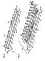
- FIG. 6is a front perspective view of a block of three jack pairs according to the present invention.
- FIG. 7is a front perspective exploded view of the block of jack pairs of FIG. 6 .
- FIG. 8is a rear perspective exploded view of the block of jack pairs of FIG. 6 .
- FIG. 9is a front perspective view of a jack pair in accordance with the present invention.
- FIG. 10is a front perspective exploded view of the jack pair of FIG. 9 .
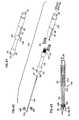
- FIG. 11is a side view of the jack pair of FIG. 9 .
- FIG. 12is an end view of the jack pair of FIG. 9 .
- FIG. 13is a bottom view of the jack pair of FIG. 9 .
- FIG. 14is an enlarged view of the portion labeled 14 in FIG. 10 , showing mating ridges and grooves of the housings of the jacks of the jack pair in greater detail.
- FIG. 15is a front perspective view of one of the jacks of the jack pair of FIG. 9 .
- FIG. 16is a rear perspective view of the jack of FIG. 15 .
- FIG. 17is a front perspective view of the jack of FIG. 15 with the jack assembly partially removed from the housing.
- FIG. 18is a rear perspective view of the jack of FIG. 16 with the jack assembly partially removed from the housing.
- FIG. 19is a front perspective view of a second embodiment of a jack pair in accordance with the present invention.
- FIG. 20is a front perspective partially exploded view of the jack pair of FIG. 19 .
- FIG. 21is a front perspective exploded view of the jack pair of FIG. 19 .
- FIG. 22is a front perspective view of a third embodiment of a jack pair in accordance with the present invention.
- FIG. 23is a front perspective partially exploded view of the jack pair of FIG. 22 .
- FIG. 24is a front perspective exploded view of the jack pair of FIG. 22 .
- FIG. 25is a side view of the jack pair of FIG. 22 .
- FIG. 26is an end view of the jack pair of FIG. 22 .
- FIG. 27is a bottom view of the jack pair of FIG. 22 .
- FIG. 28is a switching jack as shown mounted to the patch panel of FIGS. 1 , 2 , and 3 .
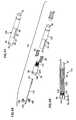
- FIG. 29is a front perspective view of one of the housings of the jack pair of FIGS. 9 , 19 and 22 .
- FIG. 30is a top view of the housing of FIG. 29 .
- FIG. 31is an end view of the housing of FIG. 29 .
- FIG. 32is a side cross-sectional view of the housing of FIG. 29 taken along line 32 - 32 in FIG. 31 .
- FIG. 33is an enlarged view of the portion labeled 33 in FIG. 31 showing the groove in greater detail.
- FIG. 34is an enlarged view of the portion labeled 34 in FIG. 31 showing the ridge in greater detail.
- FIG. 35is a perspective view of a jack assembly in accordance with the present invention.
- FIG. 36is an exploded perspective view of the jack assembly of FIG. 35 .
- FIG. 37is a side cross-sectional view of the jack assembly of FIG. 35 positioned within the housing of FIG. 29 .
- FIG. 38is a perspective view of a second embodiment of a jack assembly in accordance with the present invention.
- FIG. 39is an exploded perspective view of the jack assembly of FIG. 38 .
- FIG. 40is a side cross-sectional view of the jack assembly of FIG. 38 positioned within the housing of FIG. 29 .
- FIG. 41is a perspective view of a third embodiment of a jack assembly in accordance with the present invention.
- FIG. 42is an exploded perspective view of the jack assembly of FIG. 41 .
- FIG. 43is a side cross-sectional view of the jack assembly of FIG. 41 .
- FIG. 44is a perspective view of a fourth embodiment of a jack assembly in accordance with the present invention.
- FIG. 45is an exploded perspective view of the jack assembly of FIG. 44 .
- FIG. 46is a side cross-sectional view of the jack assembly of FIG. 44 .
- FIG. 47is a perspective view of an alternative embodiment of a jack pair according to the present invention with a unitary housing.
- Patch panelssuch as a panel 10 in FIG. 1 , might be installed in broadcast communications production facilities.
- Patch panels 10include a chassis 16 including a mounting frame 17 and a panel front 18 with a plurality of pairs of openings 20 .
- panel front 18may be removed from frame 17 to allow different configurations of openings 20 to be included in panel 10 .
- frame 17is made of a durable material such as aluminum or steel to provide structural support to chassis 16 .
- Other similar structural materialsmay be used for frame 17 such as other durable or rigid metals or composite materials.
- Panel front 18is molded or formed from plastic or other similar non-conductive material to facilitate the creation of the more complex features of panel front 18 for mounting a variety of devices to chassis 16 .
- a pair of opposing mounting flanges 22are on either side of frame 17 to facilitate mounting panel 10 to a communications equipment rack or other mounting structure in broadcast facility.
- Flanges 22include openings 24 for receiving fasteners to secure panel 10 to the rack or mounting structure.
- Jacks pairs 26 , 28 , 128 and 228 for connecting communication circuitsare mounted to a rear of panel front 18 .
- Each of these jack pairsinclude a front set of connectors accessible though one of the openings 20 in panel front 18 and a rear set of connectors accessible from the rear of panel 10 .
- the jack pairs as showninclude prior art switching jack pairs 26 and straight through jack pairs 28 , 128 and 228 . All of these jack pairs include a pair of rear connectors 30 for linking to communications cables extending behind panel 10 and a pair of front connectors 32 for connecting to communications cables extending in front of panel 10 .
- Switching pair 26provides internal circuitry so that without a plug inserted within either front connector 32 , an electrical path is defined between the pair of rear connectors 30 . No such circuitry is provided in straight through pairs 28 , 128 and 228 .
- Jack pairs 28 , 128 and 228include a pair of housings 46 , a long jack assembly or jack 48 or 148 and a short jack assembly or jack 50 or 150 . Within each housing 46 is mounted one of the jack assemblies 48 or 148 and one of the jack assemblies 50 or 150 . Jack pairs 28 , 128 and 228 , housing 46 and jacks 48 , 148 , 50 and 150 will be described in further detail below.
- Panel 110is similar to panel 10 in construction but includes a third row of openings 20 in a panel front 118 to which may be mounted monitor jacks 34 .
- Panel front 118is mounted in a frame 117 .
- Monitor jack 34also includes rear connector 30 and front connector 32 and these connectors 30 and 32 may be the same format as those of the adjacently mounted pairs 26 and 28 .
- a pair of fastener openings 36are positioned adjacent each of the openings 20 in the monitor row and adjacent each pair of openings 20 for mounting pairs 26 and 28 .
- Openings 36each receive a fastener of a jack pair 26 , 28 , 128 or 228 or a monitor jack 34 to mount these devices to panel front 118 . Similar openings 36 are also positioned on the rear of panel front 18 of panel 10 . Panel front 118 is removably mounted to frame 117 to permit the configuration of openings 20 and 36 of panel 110 to be changed.
- a tie-off bar 40extends between the two sides 38 and provides a convenient location to tie-off cables extending to the rear connectors 30 of each of the jack pairs or monitor jacks.
- a similar structure of sides 38 and rear tie-off bar 40may be added to panel 10 .
- rear connectors 30are coaxial cable connectors for receiving standard coaxial BNC connectors. Others sizes and styles of coaxial connectors may be used as well.
- Front connectors 32are coaxial cable connectors for connecting to standard size or mid size video plugs. Other sizes and styles of coaxial connectors adapted to receive video plugs may be used as well. It is also anticipated that panels 10 and 110 are not limited to use in a broadcast communications environment but may also be adapted for use in other telecommunications installations where coaxial cable connections are required.
- rear connectors 30may be staggered either horizontally or vertically to improve access to adjacent connectors. This staggering also permits a greater density of jack pairs 26 and 28 and monitor jacks 34 to mounted to panel 10 or 110 .
- rear connectors 30could be non-staggered where access and density of installation are not as great a concern.
- Monitor jacks 34are mounted to openings 20 in a monitor row 42 .
- Jack pairs 26 and 28are mounted in pairs of openings 20 in a row 44 .
- Monitor 34includes a housing 46 and either a long jack 48 or a short jack 50 mounted within an opening in housing 46 .
- FIGS. 5A and 5Bshow a third panel 210 with a single row of openings 20 with a single adjacent row of mounting openings 36 .
- Individual jacks 234 including jack assemblies 50 mounted within a single housing 46may be mounted to panel 210 .
- Panel 210may provide a separate row of monitor circuits to match up with patching circuits such as shown in panel 10 of FIG. 1 .
- jacks and housingsmay be mounted to panel 210 to provide patching or circuit connections where the number of circuits is relatively smaller and fewer jack assemblies are needed.
- Frame 217includes mounting flanges 22 with openings 24 for mounting panel 210 .
- Mounted to panel front 218is a plurality of single jacks 234 , which may be monitor jacks 34 but may also be individual patching jacks.
- module 54including three jack pairs 28 mounted to a mounting block 52 is shown. Such a module might be used when a smaller number of patching jacks are required for a particular installation. Alternatively, module 54 might be used with a patch panel including a front face adapted to receive and mount a plurality of modules 54 in a density similar to that of panels 10 and 110 , above.
- FIGS. 7 and 8show module 54 of FIG. 6 is an exploded view. Also shown in FIG. 8 is the interconnection between housings 46 of each jack pair 28 .
- Housings 46are identical housings which mate with each other along a face 56 .
- Face 56includes a ridge 58 and groove 60 .
- Housing 46also includes a mounting flange 62 positioned adjacent a first end 64 .
- Ridge 58 and groove 60are positioned and configured so that the ridge and groove of a first housing 46 cooperate with the groove and ridge, respectively, of a second housing 46 when the first and second housings 46 are positioned with faces 56 and first ends 64 adjacent each other. Ridge 58 and groove 60 , and the nature of their cooperation are described in further detail below.
- a captive fastenersuch as a screw 66 .
- Screw 66engages opening 36 of mounting block 52 and of panel front 18 to removably mount a housing 46 , a monitor jack 34 or a jack pair 28 .
- screw 66is a captive screw and remains with housing 46 when disengaged from opening 36 . It is anticipated that other captive fasteners may be used with housing 46 , such as quarter-turn fasteners and similar fasteners.
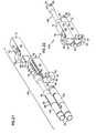
- FIGS. 9 to 14illustrate jack pair 28 .
- housing 46includes an opening 68 for receiving captive screw 66 in flange 62 .
- Screw 66includes threads which extend through first end 64 , as shown in FIGS. 7 and 8 , above.
- Housing 46also defines a longitudinal opening 70 extending from first end 64 to a second end 72 .
- Jacks 48 and 50are received within opening 70 through first end 64 so that rear connectors 30 extend through and beyond second end 72 .
- Adjacent front connector 32 of both jacks 48 and 50is a grounding housing 74 .
- Within grounding housing 74is circuitry to permit a center conductor 84 (see FIG.
- Opening 70includes an enlarged portion 76 adjacent first end 64 for receiving housing 74 .
- Enlarged portion 76does not extend through opening 70 to second end 72 and ends at an intermediate bulkhead 78 .
- Adjacent rear connectors 30 of jacks 48 and 50are a pair of opposed bayonets 80 for releasably securing a BNC cable connector to rear connector 30 .
- Each jack 48 and 50also includes a pair of opposed guide or key slots 82 .
- Each slot 82includes a closed end 88 and an open end 90 .
- Key slots 82are oriented parallel to the main axis of jacks 48 and 50 with closed end 88 toward the front connector 32 and open end 90 toward rear connector 30 .
- Key slots 82are located between grounding housing 74 and rear connector 30 .
- FIG. 14shows the cooperating shapes of ridge 58 and groove 60 .
- Ridge 58includes a dovetail shape when viewed from first end 64 or from second end 72 .
- Groove 60includes a mating shape for receiving the dovetail shape of ridge 58 . Further details of these shapes are described below with regard to FIGS. 33 and 34 .
- FIGS. 15 to 18one half of jack pair 28 is shown, including shorter jack 50 .
- an open top 96is formed, through which grounding housing 74 is visible. This open top allows maximum room for housing 74 without impeding access to screw 66 .
- a pair of opposing guides or keys 92are formed in the top and bottom of opening 70 to engage key slots 82 of jack 50 (and also of jack 48 ). Keys 92 and key slots 82 cooperate to orient jack 50 (and also jack 48 ) within housing 46 .
- Bayonets 80 and key slots 82are offset from each other about jack 50 and with keys 92 engaged in key slots 82 , bayonets 80 are oriented horizontally.
- opening 70is smaller in dimension than the width of bayonets 80 .
- Bayonet slots 94allow rear connector 30 to be inserted through first end 64 and extend through opening 70 beyond second end 72 .
- Bayonet slots 94also orient jack 50 so that key slots 82 are correctly oriented to engage keys 92 through open ends 90 .
- keys 92 adjacent bulkhead 78engage closed ends 88 of key slots 82 , and prevent further insertion of jack 50 .
- jacks 48 and 50each include grounding housing 74 .
- An alternative embodiment jack pair 128includes jacks 148 and 150 , which do not include grounding housing 74 , is shown in FIGS. 19 to 21 . In other respects, jack pair 128 is similar to jack pair 28 .
- key 92 engaging closed end 88 of key slot 82defines the limit of insertion within housings 46 .
- housing 46is configured to be compatible with multiple types and styles of jacks 48 , 50 , 148 and 150 , as well as other types and styles which may or may not include a grounding housing or another enlarged portion adjacent front connector 32 .
- FIGS. 22 to 27illustrate a further alternative embodiment jack pair 228 , with front connectors 32 configured to receive a mid-size video coaxial plug.
- jack pair 228is similar to jack pair 128 of FIGS. 19 to 21 and to jack pair 28 of FIGS. 9 to 14 .
- FIG. 28shows prior art switching jack pair 26 , including front connectors 32 configured to receive standard size video plugs and rear connectors 30 configured to receive BNC plugs.
- a pair of mounting flanges 162extend from opposing sides of a housing 146 .
- Flanges 162including openings 68 for receiving a captive fastener such as screw 66 , shown in FIGS. 16 to 19 , above. Openings 68 are positioned so that fasteners within openings 68 may engage openings 36 of panel front 18 or mounting block 52 .
- jack pairs 26 , 28 , 128 and 128may all be mounted to panel front 18 as part of patch panel 10 or 110 , or as shown in FIGS. 6 to 8 , to mounting block 52 as part of module 54 .
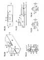
- FIGS. 29 to 34show housing 46 in further detail.
- a ledge 100extends within opening 70 from bulkhead 78 to first end 64 and defines the transition from opening 70 to enlarged portion 76 .
- Ledge 100also cooperates with bayonet slot 94 to permit bayonets 80 of rear connector 30 to extend through opening 70 in an appropriate orientation for key slot 82 to engage key 92 .
- Keys 92extend from second end 72 to bulkhead 78 and define an end wall 98 at bulkhead 78 .
- End wall 98engages closed end 88 of key slot 82 to define a stop. This stop sets the maximum extent that a jack assembly may be inserted within housing 46 .
- FIGS. 33 and 34show groove 60 and ridge 58 , respectively, in further detail.
- Ridge 58includes an outer face 114 defining a maximum width 102 at an offset distance 112 from face 56 of housing 46 .
- Ridge 58narrows as it approaches face 56 to a minimum width of 104 adjacent face 56 .
- Groove 60includes an inner face 118 defining a maximum width 106 at inset distance 116 from face 56 .
- Groove 60narrows as it approaches face 56 to a minimum width 108 adjacent face 56 .
- Ridge 58 and groove 60are sized so that width 102 fits within width 106 with face 114 adjacent face 118 , and width 104 fits within width 108 .
- Distances 112 and 116are generally equal so that when faces 56 of a pair of cooperating housings 46 are adjacent, face 114 is adjacent face 118 .
- Other similar cooperating shapesmay be used for ridge 58 and groove 60 provided they join two identical housing to each other as shown for a jack pair 28 , 128 or 228 . This joining is accomplished by sliding the housing together longitudinally while preventing the housings from being pulled apart transversely.
- the cooperation of the dovetail shape of the cooperating ridge 58 and groove 60provide several advantages. First, these shapes tie together two housings 46 to form a housing for two jacks in a jack pair, such as jacks 48 , 50 , 148 and 150 . The same housing 46 may be used to hold a single jack, such as shown in monitor jack 34 . This reduces the number of different housings that must be produced and maintained in inventory. Secondly, the dovetail configuration locks two housings together while allowing sliding movement in a longitudinal direction. No additional fasteners for connecting the two housings 46 are required. Screws 66 of each housing 46 may then be used to mount housings 46 in a module 54 or a panel 10 or 110 .
- Housings 46provide an electrically insulative sleeve about a tubular jack such as jacks 48 , 50 , 148 and 150 and also provide mechanical support to the jack to resist deflection due to strain from cables attached to rear connectors 30 , when the cable exerts a force an angle to the jacks.
- Panel 110provides a tie off bar 40 to help reduce the strain that a cable might exert on a jack.
- Panel 10does not include such a feature and thus cables attached to a rear connector 30 and hanging directly downward from rear connector 30 may exert an angled force on the jack. Cables may also be pulled toward the side or top.
- Housing 46is attached to panel front 18 by fastener 66 with first end 64 against rear face 19 , as shown in FIGS. 1 to 5 .
- housing 46For either jack pair 28 or for monitor jack 34 , this arrangement allows housing 46 to provide additional support to resist such transverse forces.
- the resistance of transverse forces and the insulative sleeve of housing 46reduce the likelihood that jacks 48 and 50 or 148 and 150 of a jack pair can be deflected enough to electrically contact each other and cause a short circuit between the two outer insulative shells 86 .
- Housing 46also provides support against the jacks being deflected enough to permanently deform or break the jacks.
- a first outer housing 134includes conductive outer shell 86 of front connector 32 as well as slot 82 .
- insulator 85within which center conductor 84 is mounted. Insulator 85 supports and isolates center conductor 84 from shell 86 . As shown, insulator 85 is made from two identical halves or, alternatively, may be made as a single piece insulator.
- a second outer housing 132includes a conductive outer shell 186 of rear connector 30 . Second outer housing 132 includes a knurled end 133 to aid insertion and retention within first outer housing 134 .
- insulator 185Mounted within second housing 132 is an insulator 185 within which a center conductor 184 is mounted. Insulator 185 supports and isolates center conductor 184 from shell 186 . As shown, insulator 185 is made from two identical halves or, alternatively, may be made as a single piece insulator. A conductive shaft 130 links center conductors 84 and 184 .
- a first outer housing 134includes conductive outer shell 86 of front connector 32 as well as slot 82 .
- insulator 85within which center conductor 84 is mounted. Insulator 85 supports and isolates center conductor 84 from shell 86 .
- insulator 85includes two identical halves.
- insulator 85may be a single piece insulator.
- a second outer housing 232includes a conductive outer shell 186 of rear connector 30 .
- Mounted within second housing 132is an insulator 185 within which a center conductor 184 is mounted. Insulator 185 supports and isolates center conductor 184 from shell 186 .
- insulator 185includes two identical halves.
- insulator 85may be a single piece insulator.
- a conductive shaft 130links center conductors 84 and 184 .
- grounding housing 74combines with a flexible conductive contact member 136 , a resistor 140 , a pad 141 and a block 142 to define a selective termination device 147 , as shown in FIGS. 36 and 39 .
- Termination device 147is mounted to first housing 134 with a first end 135 of member 136 extending through an opening 138 to contact center conductor 84 .
- a second end 137 of member 136is mounted to block 142 and is in contact with one end of resistor 140 .
- the other end of resistor 140is in electrical contact with first outer housing 134 and conductive outer shell 86 .
- Termination device 147is attached to first outer housing 132 by depressions 144 of grounding housing 74 engaging depressions 146 of housing 132 .
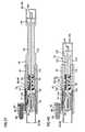
- FIGS. 41 to 43show jack assembly 148 is greater detail.
- Jack assembly 148does not include a selective termination device.
- a first outer housing 234differs from first outer housing 134 in that there is no opening providing access to center conductor 84 .
- Other aspects of jack assembly 148are similar to those of jack assembly 48 shown in FIGS. 35 to 37 .
- FIGS. 44 to 46show jack assembly 150 is greater detail.
- Jack assembly 150does not include a selective termination device.
- a first outer housing 234differs from first outer housing 134 in that there is no opening providing access to center conductor 84 .
- Other aspects of jack assembly 150are similar to those of jack assembly 50 shown in FIGS. 38 to 40 .
- FIG. 47shows an alternative jack pair 328 with jack 48 and jack 50 inserted within a pair of openings 70 in a unitary housing 346 .
- Housing 346is similar to and includes the elements described above with regard to housing 46 with the exception of first face 56 , ridge 58 and groove 60 .
- Housing 346is a single piece housing including both openings 70 .
- Housing 346provides support and strength to jacks 48 , 50 , 148 and 150 in a manner similar to housings 46 , described above.
- Housing 346is also constructed of a non-conductive material to prevent jacks 48 and 50 , or 148 and 159 , from deflected into contact with each other and creating a short circuit.
Landscapes
- Engineering & Computer Science (AREA)
- Computer Networks & Wireless Communication (AREA)
- Health & Medical Sciences (AREA)
- Toxicology (AREA)
- Coupling Device And Connection With Printed Circuit (AREA)
- Connector Housings Or Holding Contact Members (AREA)
- Details Of Connecting Devices For Male And Female Coupling (AREA)
Abstract
Description
Claims (21)
Priority Applications (2)
| Application Number | Priority Date | Filing Date | Title |
|---|---|---|---|
| US12/150,755US7780479B2 (en) | 2003-11-03 | 2008-04-29 | Jack with modular mounting sleeve |
| US12/858,002US8105115B2 (en) | 2003-11-03 | 2010-08-17 | Jack with modular mounting sleeve |
Applications Claiming Priority (5)
| Application Number | Priority Date | Filing Date | Title |
|---|---|---|---|
| US10/700,366US6848948B1 (en) | 2003-11-03 | 2003-11-03 | Jack with modular mounting sleeve |
| US10/990,814US6953368B2 (en) | 2003-11-03 | 2004-11-17 | Jack with modular mounting sleeve |
| US11/246,767US7108561B2 (en) | 2003-11-03 | 2005-10-07 | Jack with modular mounting sleeve |
| US11/488,448US7371124B2 (en) | 2003-11-03 | 2006-07-17 | Jack with modular mounting sleeve |
| US12/150,755US7780479B2 (en) | 2003-11-03 | 2008-04-29 | Jack with modular mounting sleeve |
Related Parent Applications (1)
| Application Number | Title | Priority Date | Filing Date |
|---|---|---|---|
| US11/488,448ContinuationUS7371124B2 (en) | 2003-11-03 | 2006-07-17 | Jack with modular mounting sleeve |
Related Child Applications (1)
| Application Number | Title | Priority Date | Filing Date |
|---|---|---|---|
| US12/858,002ContinuationUS8105115B2 (en) | 2003-11-03 | 2010-08-17 | Jack with modular mounting sleeve |
Publications (2)
| Publication Number | Publication Date |
|---|---|
| US20090011654A1 US20090011654A1 (en) | 2009-01-08 |
| US7780479B2true US7780479B2 (en) | 2010-08-24 |
Family
ID=34080827
Family Applications (6)
| Application Number | Title | Priority Date | Filing Date |
|---|---|---|---|
| US10/700,366Expired - LifetimeUS6848948B1 (en) | 2003-11-03 | 2003-11-03 | Jack with modular mounting sleeve |
| US10/990,814Expired - LifetimeUS6953368B2 (en) | 2003-11-03 | 2004-11-17 | Jack with modular mounting sleeve |
| US11/246,767Expired - LifetimeUS7108561B2 (en) | 2003-11-03 | 2005-10-07 | Jack with modular mounting sleeve |
| US11/488,448Expired - Fee RelatedUS7371124B2 (en) | 2003-11-03 | 2006-07-17 | Jack with modular mounting sleeve |
| US12/150,755Expired - LifetimeUS7780479B2 (en) | 2003-11-03 | 2008-04-29 | Jack with modular mounting sleeve |
| US12/858,002Expired - Fee RelatedUS8105115B2 (en) | 2003-11-03 | 2010-08-17 | Jack with modular mounting sleeve |
Family Applications Before (4)
| Application Number | Title | Priority Date | Filing Date |
|---|---|---|---|
| US10/700,366Expired - LifetimeUS6848948B1 (en) | 2003-11-03 | 2003-11-03 | Jack with modular mounting sleeve |
| US10/990,814Expired - LifetimeUS6953368B2 (en) | 2003-11-03 | 2004-11-17 | Jack with modular mounting sleeve |
| US11/246,767Expired - LifetimeUS7108561B2 (en) | 2003-11-03 | 2005-10-07 | Jack with modular mounting sleeve |
| US11/488,448Expired - Fee RelatedUS7371124B2 (en) | 2003-11-03 | 2006-07-17 | Jack with modular mounting sleeve |
Family Applications After (1)
| Application Number | Title | Priority Date | Filing Date |
|---|---|---|---|
| US12/858,002Expired - Fee RelatedUS8105115B2 (en) | 2003-11-03 | 2010-08-17 | Jack with modular mounting sleeve |
Country Status (9)
| Country | Link |
|---|---|
| US (6) | US6848948B1 (en) |
| EP (1) | EP1680841B1 (en) |
| JP (1) | JP4473275B2 (en) |
| KR (1) | KR101176389B1 (en) |
| CN (1) | CN100524966C (en) |
| AU (1) | AU2004308020B2 (en) |
| BR (1) | BRPI0415688A (en) |
| CA (1) | CA2543474C (en) |
| WO (1) | WO2005046009A1 (en) |
Cited By (1)
| Publication number | Priority date | Publication date | Assignee | Title |
|---|---|---|---|---|
| US20140154909A1 (en)* | 2012-12-04 | 2014-06-05 | Amphenol Corporation | Cable connector system |
Families Citing this family (37)
| Publication number | Priority date | Publication date | Assignee | Title |
|---|---|---|---|---|
| US6848948B1 (en)* | 2003-11-03 | 2005-02-01 | Adc Telecommunications, Inc. | Jack with modular mounting sleeve |
| US20060051982A1 (en)* | 2004-09-08 | 2006-03-09 | Huang Huang C | Combinational AV socket |
| US7175455B2 (en)* | 2005-04-15 | 2007-02-13 | Adc Telecommunications, Inc. | High density coaxial switching jack |
| WO2006115813A1 (en)* | 2005-04-21 | 2006-11-02 | Adc Telecommunications, Inc. | Modular mounting sleeve for jack |
| US7074080B1 (en)* | 2005-04-21 | 2006-07-11 | Adc Telecommunications, Inc. | Modular mounting sleeve for jack |
| US7238035B2 (en)* | 2005-06-14 | 2007-07-03 | Trompeter Electronics, Inc. | Normal-through jack with monitor and test ports |
| US7140911B1 (en) | 2005-06-27 | 2006-11-28 | Cisco Technology, Inc. | Method and apparatus for aggregating cable connectors |
| US7247058B2 (en)* | 2005-08-25 | 2007-07-24 | Tyco Electronics Corporation | Vertical docking connector |
| US7591677B2 (en)* | 2006-04-21 | 2009-09-22 | Adc Telecommunications, Inc. | High density coaxial jack and panel |
| US7393249B2 (en)* | 2006-04-21 | 2008-07-01 | Trompeter Electronics, Inc. | Interconnection and monitoring module |
| US7244131B1 (en) | 2006-04-21 | 2007-07-17 | Adc Telecommunications, Inc. | High density coaxial jack |
| US7163423B1 (en)* | 2006-04-21 | 2007-01-16 | Adc Telecommunications, Inc. | Coaxial system with keying feature |
| US7438592B2 (en)* | 2006-04-21 | 2008-10-21 | Adc Telecommunications, Inc. | Designation tray for telecommunications panel |
| USD559182S1 (en) | 2006-11-27 | 2008-01-08 | Cisco Technology, Inc. | Cable connector module |
| US7699617B2 (en)* | 2007-10-08 | 2010-04-20 | Winchester Electronics Corporation | Modular interconnect apparatus |
| US20090182566A1 (en)* | 2008-01-10 | 2009-07-16 | Kulvir Singh Bhogal | Automatic Library Referral System and Method |
| KR100963424B1 (en)* | 2008-07-23 | 2010-06-15 | 한국전자통신연구원 | Scalable video decoder and control method thereof |
| US7780467B2 (en) | 2008-09-17 | 2010-08-24 | Tyco Electronics Corporation | Poke-in connector |
| CN101752759A (en)* | 2008-11-28 | 2010-06-23 | 鸿富锦精密工业(深圳)有限公司 | Connector device |
| DE102009010492B3 (en)* | 2009-02-25 | 2010-05-27 | Harting Electric Gmbh & Co. Kg | Cable organizer Insert for connectors |
| US8550859B2 (en) | 2011-10-20 | 2013-10-08 | Andrew Llc | Close proximity panel mount connectors |
| JP6082648B2 (en)* | 2013-04-26 | 2017-02-15 | 矢崎総業株式会社 | connector |
| DE102013112101B4 (en)* | 2013-11-04 | 2018-05-09 | Phoenix Contact Gmbh & Co. Kg | Components Mounting System |
| DE102014104902A1 (en)* | 2014-04-07 | 2015-10-08 | Harting Electric Gmbh & Co. Kg | Mudguard for a connector system |
| CN103944026B (en)* | 2014-04-24 | 2016-05-18 | 上海元动利投资有限公司 | A kind of socket can 360 the adjustable insert row of distance between degree rotation and adjacent outlet |
| DE102015119087A1 (en)* | 2015-11-06 | 2017-05-11 | Beckhoff Automation Gmbh | Hybrid connector |
| US9601879B1 (en)* | 2016-03-01 | 2017-03-21 | GM Global Technology Operations LLC | Methods for detecting loose connection in power connectors |
| US10181692B2 (en)* | 2016-11-07 | 2019-01-15 | Corning Optical Communications Rf Llc | Coaxial connector with translating grounding collar for establishing a ground path with a mating connector |
| US9979132B1 (en)* | 2017-04-28 | 2018-05-22 | Corning Optical Communications Rf Llc | Coaxial connectors with grounding tube for altering a ground path with a conductor |
| CN108565651B (en)* | 2018-04-04 | 2023-09-29 | 临沂市海纳电子有限公司 | Radio frequency coaxial connector with low contact resistance |
| JP6914905B2 (en)* | 2018-11-29 | 2021-08-04 | 矢崎総業株式会社 | Bonder cap containment structure, electrical junction box, and wire harness |
| JP2020205164A (en)* | 2019-06-17 | 2020-12-24 | 株式会社オートネットワーク技術研究所 | connector |
| US11025006B2 (en)* | 2019-09-04 | 2021-06-01 | Te Connectivity Corporation | Communication system having connector assembly |
| CN115104226A (en) | 2019-12-12 | 2022-09-23 | 富加宜(美国)有限责任公司 | Card edge connector system with bus bar connections for high power applications |
| CN111585120B (en)* | 2020-06-22 | 2025-07-15 | 东莞市纳百川电子科技有限公司 | A spacer connector assembly and electrical application system thereof |
| US12176637B2 (en) | 2021-02-09 | 2024-12-24 | Fci Usa Llc | Electrical connector for high power computing system |
| KR20230160839A (en)* | 2021-03-30 | 2023-11-24 | 스타우블리 일렉트리컬 커넥털스 아게 | electrical connector |
Citations (93)
| Publication number | Priority date | Publication date | Assignee | Title |
|---|---|---|---|---|
| US2925577A (en) | 1958-06-10 | 1960-02-16 | Royal Mcbee Corp | Terminal block connector assembly |
| US3020365A (en) | 1959-04-23 | 1962-02-06 | Columbia Broadcasting Syst Inc | Self-normalling video jack |
| US3109997A (en) | 1961-07-10 | 1963-11-05 | Bell Telephone Labor Inc | Double circuit coaxial jack with automatic cross-connection upon plug removal and automatic termination of idle line upon plug insertion |
| US3556334A (en) | 1969-05-01 | 1971-01-19 | Flexible Plastics Corp | Resealable container |
| US3663901A (en) | 1970-02-27 | 1972-05-16 | Amp Inc | Tuned coaxial device |
| US3701083A (en) | 1968-05-27 | 1972-10-24 | Amp Inc | Coaxial connector mounting means |
| US3873785A (en) | 1973-10-25 | 1975-03-25 | Magnetic Controls Co | Electrical connector |
| US3946390A (en) | 1975-04-07 | 1976-03-23 | Motorola, Inc. | Radio frequency connector system for portable radios |
| US3980385A (en) | 1973-10-01 | 1976-09-14 | Shinagawa Automotive Electric Wire Co., Ltd. | Electrical connector |
| US4099825A (en) | 1977-08-24 | 1978-07-11 | Kings Electronics Co., Inc. | Coaxial adapter |
| US4231003A (en) | 1977-12-21 | 1980-10-28 | The Director-General Of National Laboratory For High Energy Physics | Shield-type coaxial vacuum feedthrough |
| US4264115A (en) | 1978-03-01 | 1981-04-28 | Bunker Ramo Corporation | Interstage electrical connector |
| US4749968A (en) | 1985-12-13 | 1988-06-07 | Adc Telecommunications, Inc. | Jack device |
| US4789351A (en) | 1988-04-29 | 1988-12-06 | Amp Incorporated | Blind mating connector with snap ring insertion |
| US4815104A (en) | 1988-01-11 | 1989-03-21 | Telect, Inc. | Digital telecommunications network, cross-connect module |
| US4820200A (en) | 1987-02-13 | 1989-04-11 | Switchcraft, Inc. | Slab-like jack module |
| US4824399A (en) | 1987-06-19 | 1989-04-25 | Amp Incorporated | Phase shifter |
| US4925403A (en) | 1988-10-11 | 1990-05-15 | Gilbert Engineering Company, Inc. | Coaxial transmission medium connector |
| US4938707A (en) | 1989-03-16 | 1990-07-03 | Adams-Russell Electronic Company, Inc. | Multimate coaxial adapter |
| US4941846A (en) | 1989-05-31 | 1990-07-17 | Adams-Russell Electronic Company, Inc. | Quick connect/disconnect microwave connector |
| US4950840A (en) | 1983-08-08 | 1990-08-21 | Zetena Maurice F | Wall recess cable connector permitting simplified innerconnection and limiting protruding cables |
| US4971578A (en) | 1988-09-26 | 1990-11-20 | Microwave Development Laboratories, Inc. | Electrical connector |
| US4971569A (en) | 1989-06-21 | 1990-11-20 | Apple Computer, Inc. | Self-terminating coaxial tap connector |
| US5090915A (en) | 1990-10-11 | 1992-02-25 | Apple Computer, Inc. | Self-terminating coaxial tap connector with external termination element |
| US5096444A (en) | 1991-01-03 | 1992-03-17 | Regal Technologies, Ltd. | Flat F-port connector |
| US5194020A (en) | 1991-06-17 | 1993-03-16 | W. L. Gore & Associates, Inc. | High-density coaxial interconnect system |
| US5233501A (en) | 1992-02-27 | 1993-08-03 | Telect, Inc. | Digital telecommunication network cross-connect module having a printed circuit board connected to jack switches |
| US5246378A (en) | 1989-08-09 | 1993-09-21 | Trimm, Inc. | Coaxial jack assembly |
| EP0561238A2 (en) | 1992-03-18 | 1993-09-22 | Bayer Ag | Use of salts in combination with halogenated phthalimides for flame protection of polycarbonates containing glass fibres |
| US5280254A (en) | 1992-03-16 | 1994-01-18 | Trompeter Electronics, Inc. | Connector assembly |
| US5329262A (en) | 1991-06-24 | 1994-07-12 | The Whitaker Corporation | Fixed RF connector having internal floating members with impedance compensation |
| US5348491A (en) | 1993-10-29 | 1994-09-20 | Adc Telecommunications, Inc. | Jack module |
| US5382173A (en) | 1993-09-01 | 1995-01-17 | Trompeter Electronics, Inc. | Electrical connector |
| US5417588A (en) | 1993-11-15 | 1995-05-23 | Adc Telecommunications, Inc. | Coax connector with center pin locking |
| US5450011A (en) | 1992-05-07 | 1995-09-12 | U.S. Philips Corporation | Magnetic resonance apparatus having a wideband matching network |
| US5467062A (en) | 1992-04-02 | 1995-11-14 | Adc Telecommunications, Inc. | Miniature coax jack module |
| US5475394A (en) | 1991-01-30 | 1995-12-12 | Comsat Corporation | Waveguide transition for flat plate antenna |
| US5482469A (en) | 1993-07-21 | 1996-01-09 | Trimm, Inc. | Dual monitor self-contained six port digital signal cross-connect module |
| US5489222A (en) | 1994-09-09 | 1996-02-06 | The Whitaker Corporation | Mini connector with anti-rotational contact |
| US5498175A (en) | 1994-01-06 | 1996-03-12 | Yeh; Ming-Hwa | Coaxial cable connector |
| US5503566A (en) | 1994-10-05 | 1996-04-02 | Wang; Tsan C. | Computer network distribution system |
| US5518414A (en) | 1994-06-28 | 1996-05-21 | Kings Electronics Co., Inc. | Electrical connector with floating V-spring continuity bridge |
| US5567179A (en) | 1995-02-10 | 1996-10-22 | W. L. Gore & Associates, Inc. | Connector system for coaxial cables |
| US5577924A (en) | 1995-01-09 | 1996-11-26 | Adc Telecommunications, Inc. | Jack module with inductive monitor |
| WO1996037929A1 (en) | 1995-05-22 | 1996-11-28 | Adc Telecommunications, Inc. | Switching coax jack with amplified monitor |
| US5585768A (en) | 1995-07-12 | 1996-12-17 | Microelectronics Technology Inc. | Electromagnetic wave conversion device for receiving first and second signal components |
| US5599198A (en) | 1995-03-10 | 1997-02-04 | Wang; Tsan-Chi | Auto by-pass distributor for computer networks |
| US5654679A (en) | 1996-06-13 | 1997-08-05 | Rf Power Products, Inc. | Apparatus for matching a variable load impedance with an RF power generator impedance |
| US5700160A (en) | 1996-11-19 | 1997-12-23 | Super Group Co., Ltd. | Electrical connector for interconnecting female and male contacts of cables |
| US5702262A (en) | 1996-10-04 | 1997-12-30 | Trompeter Electronics, Inc. | Connector assembly |
| EP0706723B1 (en) | 1993-06-30 | 1998-05-13 | Adc Telecommunications, Inc. | Rear cross connect dsx system |
| US5865654A (en) | 1997-01-23 | 1999-02-02 | Raychem Corporation | Coaxial cable connector |
| US5876253A (en) | 1996-01-23 | 1999-03-02 | Molex Incorporated | Electrical connector with improved terminal latching system |
| US5885096A (en) | 1997-04-04 | 1999-03-23 | Adc Telecommunications, Inc. | Switching coaxial jack |
| US5913701A (en) | 1997-02-28 | 1999-06-22 | Adc Telecommunications, Inc. | DSX module with removable switching jack |
| US5964607A (en) | 1997-04-04 | 1999-10-12 | Adc Telecommunications, Inc. | Coaxial switching jack with sliding center conductor |
| US6045378A (en) | 1998-03-27 | 2000-04-04 | Adc Telecommunications, Inc. | Switching coaxial jack with impedance matching |
| US6062910A (en) | 1998-05-28 | 2000-05-16 | International Business Machines Corporation | Capacitive cable adapter |
| US6065997A (en) | 1998-03-20 | 2000-05-23 | Jye Dyi C Industrial Co., Ltd. | Terminal connector structure for cable television |
| US6113431A (en) | 1998-12-04 | 2000-09-05 | Wong; Shen-Chia | Flat F-port coaxial electrical connector |
| US6213801B1 (en) | 2000-04-07 | 2001-04-10 | Kings Electronics Co., Inc. | Electrical coupling and switching device with flexible microstrip |
| US6224421B1 (en) | 2000-02-29 | 2001-05-01 | Palco Connector, Inc. | Multi-part connector |
| US6227868B1 (en) | 2000-05-05 | 2001-05-08 | Antoine Wlodarski | Coaxial cable connector |
| US6241562B1 (en) | 1999-06-22 | 2001-06-05 | Avaya Technology Corp. | Digital cross connect/interconnect module |
| EP1107368A2 (en) | 1999-12-07 | 2001-06-13 | Molex Incorporated | Mounting system for a connector assembly to a substrate |
| US6250960B1 (en) | 2000-07-12 | 2001-06-26 | Pct International, Inc. | Female to female CATV splice connector |
| US6276970B1 (en) | 2000-10-16 | 2001-08-21 | Shen-Chia Wong | Flat F-port coaxial electrical connector |
| US6409550B1 (en) | 1999-11-15 | 2002-06-25 | Mce/Weinschel Corporation | Planar blind-mate connectors |
| US6504726B1 (en) | 2001-11-16 | 2003-01-07 | Adc Telecommunications, Inc. | Telecommunications patch panel |
| US6511330B1 (en) | 2001-08-24 | 2003-01-28 | Adc Telecommunications, Inc. | Interconnect module |
| US6533616B2 (en) | 2001-04-13 | 2003-03-18 | Adc Telecommunications, Inc. | DSX jack including sliding rear connector |
| US6575792B2 (en) | 1998-11-12 | 2003-06-10 | Adc Telecommunications, Inc. | Jack assembly |
| US6589062B1 (en) | 1999-04-06 | 2003-07-08 | Adc Telecommunications, Inc. | DSX module with removable jack |
| US6597256B2 (en) | 2001-01-23 | 2003-07-22 | Adc Telecommunications, Inc. | Multi-circuit signal transformer |
| US6608764B2 (en) | 2001-11-16 | 2003-08-19 | Adc Telecommunications, Inc. | Telecommunications patch panel |
| US6743032B2 (en) | 1999-04-06 | 2004-06-01 | Adc Telecommunications, Inc. | Digital cross connect module with removable jack |
| US6752665B2 (en) | 2002-11-18 | 2004-06-22 | Trompeter Electronics, Inc. | Modular cross-connect with removable switch assembly |
| US6761588B2 (en) | 2002-01-09 | 2004-07-13 | Clark Heebe | Coaxial cable quick connect/disconnect connector |
| US6790080B2 (en) | 2002-10-29 | 2004-09-14 | Agilent Technologies, Inc. | Sub-chassis orienting connectors for a motherboard and mounted to a panel prevents connector rotation |
| US6808426B2 (en) | 2003-03-21 | 2004-10-26 | Ai Ti Ya Industrial Co., Ltd. | Structure of a signal adapter |
| US6811432B2 (en) | 1999-03-31 | 2004-11-02 | Adc Telecommunications, Inc. | Bulkhead connector system including angled adapter |
| US6817876B2 (en) | 2002-06-07 | 2004-11-16 | Switchcraft, Inc. | High frequency coaxial jack |
| US6830486B2 (en) | 2002-07-19 | 2004-12-14 | Adc Telecommunications, Inc. | Digital switching cross-connect module |
| US6835093B1 (en) | 2002-12-13 | 2004-12-28 | Pic Wire & Cable/The Angelus Corporation | Multiple jack bulkhead feedthrough adapter |
| US6846195B2 (en) | 2002-07-16 | 2005-01-25 | Radiall | Housing for a coaxial connector element, and a coaxial connector element |
| US6848948B1 (en) | 2003-11-03 | 2005-02-01 | Adc Telecommunications, Inc. | Jack with modular mounting sleeve |
| US6881076B2 (en) | 2003-02-28 | 2005-04-19 | Adc Telecommunications, Inc. | Coaxial module with surge protector |
| US6905363B2 (en) | 2002-08-14 | 2005-06-14 | Adc Telecommunications, Inc. | Cross-connect jumper assembly having tracer lamp |
| US6945817B2 (en) | 2003-03-24 | 2005-09-20 | Autonetworks Technologies, Ltd. | Connecting structure for electric wire to shield case of apparatus |
| US7070457B2 (en) | 2002-07-19 | 2006-07-04 | Adc Telecommunications, Inc. | Telecommunications connector |
| US7074080B1 (en) | 2005-04-21 | 2006-07-11 | Adc Telecommunications, Inc. | Modular mounting sleeve for jack |
| US7128604B2 (en) | 2004-06-14 | 2006-10-31 | Corning Gilbert Inc. | High power coaxial interconnect |
| US7175455B2 (en) | 2005-04-15 | 2007-02-13 | Adc Telecommunications, Inc. | High density coaxial switching jack |
Family Cites Families (7)
| Publication number | Priority date | Publication date | Assignee | Title |
|---|---|---|---|---|
| US355634A (en)* | 1887-01-04 | And benjamin w | ||
| US317A (en)* | 1837-07-29 | Machine for dressing or smoothing- sawed shingles | ||
| LU86521A1 (en)* | 1986-07-18 | 1988-02-02 | Oreal | HAIR DYEING PROCESS WITH HYDROXYQUINONIC DYES AND METAL SALTS |
| US5448469A (en)* | 1990-02-15 | 1995-09-05 | Deutsche Thomson-Brandt Gmbh | Switch mode power supply with output feedback isolation |
| CN2376105Y (en)* | 1999-03-12 | 2000-04-26 | 胡嘉惠 | Improved socket structure |
| CN2428875Y (en)* | 2000-05-26 | 2001-05-02 | 富士康(昆山)电脑接插件有限公司 | Socket connector |
| CN2565163Y (en)* | 2002-08-30 | 2003-08-06 | 连展科技(深圳)有限公司 | Eccentric socket connector |
- 2003
- 2003-11-03USUS10/700,366patent/US6848948B1/ennot_activeExpired - Lifetime
- 2004
- 2004-10-29BRBRPI0415688-9Apatent/BRPI0415688A/ennot_activeIP Right Cessation
- 2004-10-29AUAU2004308020Apatent/AU2004308020B2/ennot_activeCeased
- 2004-10-29EPEP04818332.1Apatent/EP1680841B1/ennot_activeExpired - Lifetime
- 2004-10-29WOPCT/US2004/036016patent/WO2005046009A1/enactiveApplication Filing
- 2004-10-29CACA2543474Apatent/CA2543474C/ennot_activeExpired - Fee Related
- 2004-10-29JPJP2006538308Apatent/JP4473275B2/ennot_activeExpired - Fee Related
- 2004-10-29KRKR1020067010960Apatent/KR101176389B1/ennot_activeExpired - Fee Related
- 2004-10-29CNCNB2004800323587Apatent/CN100524966C/ennot_activeExpired - Fee Related
- 2004-11-17USUS10/990,814patent/US6953368B2/ennot_activeExpired - Lifetime
- 2005
- 2005-10-07USUS11/246,767patent/US7108561B2/ennot_activeExpired - Lifetime
- 2006
- 2006-07-17USUS11/488,448patent/US7371124B2/ennot_activeExpired - Fee Related
- 2008
- 2008-04-29USUS12/150,755patent/US7780479B2/ennot_activeExpired - Lifetime
- 2010
- 2010-08-17USUS12/858,002patent/US8105115B2/ennot_activeExpired - Fee Related
Patent Citations (101)
| Publication number | Priority date | Publication date | Assignee | Title |
|---|---|---|---|---|
| US2925577A (en) | 1958-06-10 | 1960-02-16 | Royal Mcbee Corp | Terminal block connector assembly |
| US3020365A (en) | 1959-04-23 | 1962-02-06 | Columbia Broadcasting Syst Inc | Self-normalling video jack |
| US3109997A (en) | 1961-07-10 | 1963-11-05 | Bell Telephone Labor Inc | Double circuit coaxial jack with automatic cross-connection upon plug removal and automatic termination of idle line upon plug insertion |
| US3701083A (en) | 1968-05-27 | 1972-10-24 | Amp Inc | Coaxial connector mounting means |
| US3556334A (en) | 1969-05-01 | 1971-01-19 | Flexible Plastics Corp | Resealable container |
| US3663901A (en) | 1970-02-27 | 1972-05-16 | Amp Inc | Tuned coaxial device |
| US3980385A (en) | 1973-10-01 | 1976-09-14 | Shinagawa Automotive Electric Wire Co., Ltd. | Electrical connector |
| US3873785A (en) | 1973-10-25 | 1975-03-25 | Magnetic Controls Co | Electrical connector |
| US3946390A (en) | 1975-04-07 | 1976-03-23 | Motorola, Inc. | Radio frequency connector system for portable radios |
| US4099825A (en) | 1977-08-24 | 1978-07-11 | Kings Electronics Co., Inc. | Coaxial adapter |
| US4231003A (en) | 1977-12-21 | 1980-10-28 | The Director-General Of National Laboratory For High Energy Physics | Shield-type coaxial vacuum feedthrough |
| US4264115A (en) | 1978-03-01 | 1981-04-28 | Bunker Ramo Corporation | Interstage electrical connector |
| US4950840A (en) | 1983-08-08 | 1990-08-21 | Zetena Maurice F | Wall recess cable connector permitting simplified innerconnection and limiting protruding cables |
| US4749968A (en) | 1985-12-13 | 1988-06-07 | Adc Telecommunications, Inc. | Jack device |
| US4820200A (en) | 1987-02-13 | 1989-04-11 | Switchcraft, Inc. | Slab-like jack module |
| US4824399A (en) | 1987-06-19 | 1989-04-25 | Amp Incorporated | Phase shifter |
| US4815104A (en) | 1988-01-11 | 1989-03-21 | Telect, Inc. | Digital telecommunications network, cross-connect module |
| US4815104B1 (en) | 1988-01-11 | 1991-07-02 | Telect Inc | |
| US4789351A (en) | 1988-04-29 | 1988-12-06 | Amp Incorporated | Blind mating connector with snap ring insertion |
| US4971578A (en) | 1988-09-26 | 1990-11-20 | Microwave Development Laboratories, Inc. | Electrical connector |
| US4925403A (en) | 1988-10-11 | 1990-05-15 | Gilbert Engineering Company, Inc. | Coaxial transmission medium connector |
| US4938707A (en) | 1989-03-16 | 1990-07-03 | Adams-Russell Electronic Company, Inc. | Multimate coaxial adapter |
| US4941846A (en) | 1989-05-31 | 1990-07-17 | Adams-Russell Electronic Company, Inc. | Quick connect/disconnect microwave connector |
| US4971569A (en) | 1989-06-21 | 1990-11-20 | Apple Computer, Inc. | Self-terminating coaxial tap connector |
| US5246378A (en) | 1989-08-09 | 1993-09-21 | Trimm, Inc. | Coaxial jack assembly |
| US5090915A (en) | 1990-10-11 | 1992-02-25 | Apple Computer, Inc. | Self-terminating coaxial tap connector with external termination element |
| US5096444A (en) | 1991-01-03 | 1992-03-17 | Regal Technologies, Ltd. | Flat F-port connector |
| US5475394A (en) | 1991-01-30 | 1995-12-12 | Comsat Corporation | Waveguide transition for flat plate antenna |
| US5194020A (en) | 1991-06-17 | 1993-03-16 | W. L. Gore & Associates, Inc. | High-density coaxial interconnect system |
| US5329262A (en) | 1991-06-24 | 1994-07-12 | The Whitaker Corporation | Fixed RF connector having internal floating members with impedance compensation |
| US5233501A (en) | 1992-02-27 | 1993-08-03 | Telect, Inc. | Digital telecommunication network cross-connect module having a printed circuit board connected to jack switches |
| US5280254A (en) | 1992-03-16 | 1994-01-18 | Trompeter Electronics, Inc. | Connector assembly |
| EP0561238A2 (en) | 1992-03-18 | 1993-09-22 | Bayer Ag | Use of salts in combination with halogenated phthalimides for flame protection of polycarbonates containing glass fibres |
| US5467062A (en) | 1992-04-02 | 1995-11-14 | Adc Telecommunications, Inc. | Miniature coax jack module |
| US5450011A (en) | 1992-05-07 | 1995-09-12 | U.S. Philips Corporation | Magnetic resonance apparatus having a wideband matching network |
| EP0706723B1 (en) | 1993-06-30 | 1998-05-13 | Adc Telecommunications, Inc. | Rear cross connect dsx system |
| US5482469A (en) | 1993-07-21 | 1996-01-09 | Trimm, Inc. | Dual monitor self-contained six port digital signal cross-connect module |
| US5382173A (en) | 1993-09-01 | 1995-01-17 | Trompeter Electronics, Inc. | Electrical connector |
| US5348491A (en) | 1993-10-29 | 1994-09-20 | Adc Telecommunications, Inc. | Jack module |
| US5417588A (en) | 1993-11-15 | 1995-05-23 | Adc Telecommunications, Inc. | Coax connector with center pin locking |
| US5498175A (en) | 1994-01-06 | 1996-03-12 | Yeh; Ming-Hwa | Coaxial cable connector |
| US5518414A (en) | 1994-06-28 | 1996-05-21 | Kings Electronics Co., Inc. | Electrical connector with floating V-spring continuity bridge |
| US5489222A (en) | 1994-09-09 | 1996-02-06 | The Whitaker Corporation | Mini connector with anti-rotational contact |
| US5503566A (en) | 1994-10-05 | 1996-04-02 | Wang; Tsan C. | Computer network distribution system |
| US5577924A (en) | 1995-01-09 | 1996-11-26 | Adc Telecommunications, Inc. | Jack module with inductive monitor |
| US5567179A (en) | 1995-02-10 | 1996-10-22 | W. L. Gore & Associates, Inc. | Connector system for coaxial cables |
| US5599198A (en) | 1995-03-10 | 1997-02-04 | Wang; Tsan-Chi | Auto by-pass distributor for computer networks |
| WO1996037929A1 (en) | 1995-05-22 | 1996-11-28 | Adc Telecommunications, Inc. | Switching coax jack with amplified monitor |
| US5585768A (en) | 1995-07-12 | 1996-12-17 | Microelectronics Technology Inc. | Electromagnetic wave conversion device for receiving first and second signal components |
| US5876253A (en) | 1996-01-23 | 1999-03-02 | Molex Incorporated | Electrical connector with improved terminal latching system |
| US5654679A (en) | 1996-06-13 | 1997-08-05 | Rf Power Products, Inc. | Apparatus for matching a variable load impedance with an RF power generator impedance |
| US5702262A (en) | 1996-10-04 | 1997-12-30 | Trompeter Electronics, Inc. | Connector assembly |
| US5700160A (en) | 1996-11-19 | 1997-12-23 | Super Group Co., Ltd. | Electrical connector for interconnecting female and male contacts of cables |
| US5865654A (en) | 1997-01-23 | 1999-02-02 | Raychem Corporation | Coaxial cable connector |
| US6572413B2 (en) | 1997-02-28 | 2003-06-03 | Adc Telecommunications, Inc. | DSX module with removable jack |
| US5913701A (en) | 1997-02-28 | 1999-06-22 | Adc Telecommunications, Inc. | DSX module with removable switching jack |
| US5885096A (en) | 1997-04-04 | 1999-03-23 | Adc Telecommunications, Inc. | Switching coaxial jack |
| US5964607A (en) | 1997-04-04 | 1999-10-12 | Adc Telecommunications, Inc. | Coaxial switching jack with sliding center conductor |
| US6065997A (en) | 1998-03-20 | 2000-05-23 | Jye Dyi C Industrial Co., Ltd. | Terminal connector structure for cable television |
| US6045378A (en) | 1998-03-27 | 2000-04-04 | Adc Telecommunications, Inc. | Switching coaxial jack with impedance matching |
| US6062910A (en) | 1998-05-28 | 2000-05-16 | International Business Machines Corporation | Capacitive cable adapter |
| US6575792B2 (en) | 1998-11-12 | 2003-06-10 | Adc Telecommunications, Inc. | Jack assembly |
| US6881099B2 (en) | 1998-11-12 | 2005-04-19 | Adc Telecommunications, Inc. | Jack assembly |
| US6113431A (en) | 1998-12-04 | 2000-09-05 | Wong; Shen-Chia | Flat F-port coaxial electrical connector |
| US6811432B2 (en) | 1999-03-31 | 2004-11-02 | Adc Telecommunications, Inc. | Bulkhead connector system including angled adapter |
| US6589062B1 (en) | 1999-04-06 | 2003-07-08 | Adc Telecommunications, Inc. | DSX module with removable jack |
| US6743032B2 (en) | 1999-04-06 | 2004-06-01 | Adc Telecommunications, Inc. | Digital cross connect module with removable jack |
| US6241562B1 (en) | 1999-06-22 | 2001-06-05 | Avaya Technology Corp. | Digital cross connect/interconnect module |
| US6409550B1 (en) | 1999-11-15 | 2002-06-25 | Mce/Weinschel Corporation | Planar blind-mate connectors |
| EP1107368A2 (en) | 1999-12-07 | 2001-06-13 | Molex Incorporated | Mounting system for a connector assembly to a substrate |
| US6224421B1 (en) | 2000-02-29 | 2001-05-01 | Palco Connector, Inc. | Multi-part connector |
| US6213801B1 (en) | 2000-04-07 | 2001-04-10 | Kings Electronics Co., Inc. | Electrical coupling and switching device with flexible microstrip |
| US6227868B1 (en) | 2000-05-05 | 2001-05-08 | Antoine Wlodarski | Coaxial cable connector |
| US6250960B1 (en) | 2000-07-12 | 2001-06-26 | Pct International, Inc. | Female to female CATV splice connector |
| US6276970B1 (en) | 2000-10-16 | 2001-08-21 | Shen-Chia Wong | Flat F-port coaxial electrical connector |
| US6597256B2 (en) | 2001-01-23 | 2003-07-22 | Adc Telecommunications, Inc. | Multi-circuit signal transformer |
| US6761594B2 (en) | 2001-04-13 | 2004-07-13 | Adc Telecommunications, Inc. | DSX jack including sliding rear connector |
| US6533616B2 (en) | 2001-04-13 | 2003-03-18 | Adc Telecommunications, Inc. | DSX jack including sliding rear connector |
| US6872097B2 (en) | 2001-04-13 | 2005-03-29 | Adc Telecommunications, Inc. | Dsx jack including sliding rear connector |
| US6511330B1 (en) | 2001-08-24 | 2003-01-28 | Adc Telecommunications, Inc. | Interconnect module |
| US6608764B2 (en) | 2001-11-16 | 2003-08-19 | Adc Telecommunications, Inc. | Telecommunications patch panel |
| US6504726B1 (en) | 2001-11-16 | 2003-01-07 | Adc Telecommunications, Inc. | Telecommunications patch panel |
| US6761588B2 (en) | 2002-01-09 | 2004-07-13 | Clark Heebe | Coaxial cable quick connect/disconnect connector |
| US6817876B2 (en) | 2002-06-07 | 2004-11-16 | Switchcraft, Inc. | High frequency coaxial jack |
| US6932634B2 (en) | 2002-06-07 | 2005-08-23 | Switchcarft, Inc. | High frequency coaxial jack |
| US6846195B2 (en) | 2002-07-16 | 2005-01-25 | Radiall | Housing for a coaxial connector element, and a coaxial connector element |
| US7070457B2 (en) | 2002-07-19 | 2006-07-04 | Adc Telecommunications, Inc. | Telecommunications connector |
| US6830486B2 (en) | 2002-07-19 | 2004-12-14 | Adc Telecommunications, Inc. | Digital switching cross-connect module |
| US6905363B2 (en) | 2002-08-14 | 2005-06-14 | Adc Telecommunications, Inc. | Cross-connect jumper assembly having tracer lamp |
| US6790080B2 (en) | 2002-10-29 | 2004-09-14 | Agilent Technologies, Inc. | Sub-chassis orienting connectors for a motherboard and mounted to a panel prevents connector rotation |
| US6752665B2 (en) | 2002-11-18 | 2004-06-22 | Trompeter Electronics, Inc. | Modular cross-connect with removable switch assembly |
| US6835093B1 (en) | 2002-12-13 | 2004-12-28 | Pic Wire & Cable/The Angelus Corporation | Multiple jack bulkhead feedthrough adapter |
| US6881076B2 (en) | 2003-02-28 | 2005-04-19 | Adc Telecommunications, Inc. | Coaxial module with surge protector |
| US6808426B2 (en) | 2003-03-21 | 2004-10-26 | Ai Ti Ya Industrial Co., Ltd. | Structure of a signal adapter |
| US6945817B2 (en) | 2003-03-24 | 2005-09-20 | Autonetworks Technologies, Ltd. | Connecting structure for electric wire to shield case of apparatus |
| US6848948B1 (en) | 2003-11-03 | 2005-02-01 | Adc Telecommunications, Inc. | Jack with modular mounting sleeve |
| US6953368B2 (en)* | 2003-11-03 | 2005-10-11 | Adc Telecommunications, Inc. | Jack with modular mounting sleeve |
| US7108561B2 (en) | 2003-11-03 | 2006-09-19 | Adc Telecommunications, Inc. | Jack with modular mounting sleeve |
| US7128604B2 (en) | 2004-06-14 | 2006-10-31 | Corning Gilbert Inc. | High power coaxial interconnect |
| US7175455B2 (en) | 2005-04-15 | 2007-02-13 | Adc Telecommunications, Inc. | High density coaxial switching jack |
| US7074080B1 (en) | 2005-04-21 | 2006-07-11 | Adc Telecommunications, Inc. | Modular mounting sleeve for jack |
Non-Patent Citations (5)
| Title |
|---|
| ADC Telecommunications, Inc. "Broadcast Products," 11th Edition, Publication No. 1180270, front cover, table of contents, pp. 1-16, 45-67, 172-191, back cover (Aug. 2003). |
| Canford Audio Video Jackfield 12 photos (known as prior art at least as early as Nov. 3, 2003). |
| Exhibit A, Article entitled "Avoiding the Pitfalls in Serial Digital Signal Distribution," from SMPTE Journal, pp. 14-23 (Jan. 1993). |
| Exhibit B, Kings Electronic Co. Inc. Broadcast Video Products Catalog, front cover page, pp. 1 and 7, and back cover page (1991). |
| Exhibit C, Photographs of a Kings Electronic Co. Inc. Video Jack Part No. 7400-1, 1 page (known as prior art at least as early as Nov. 3, 2003). |
Cited By (2)
| Publication number | Priority date | Publication date | Assignee | Title |
|---|---|---|---|---|
| US20140154909A1 (en)* | 2012-12-04 | 2014-06-05 | Amphenol Corporation | Cable connector system |
| US8834195B2 (en)* | 2012-12-04 | 2014-09-16 | Amphenol Corporation | Cable connector system |
Also Published As
| Publication number | Publication date |
|---|---|
| CN100524966C (en) | 2009-08-05 |
| KR101176389B1 (en) | 2012-08-27 |
| CA2543474A1 (en) | 2005-05-19 |
| JP2007511050A (en) | 2007-04-26 |
| CA2543474C (en) | 2012-06-19 |
| AU2004308020B2 (en) | 2010-02-11 |
| KR20060123251A (en) | 2006-12-01 |
| EP1680841B1 (en) | 2015-04-08 |
| JP4473275B2 (en) | 2010-06-02 |
| US20090011654A1 (en) | 2009-01-08 |
| US8105115B2 (en) | 2012-01-31 |
| US20050095900A1 (en) | 2005-05-05 |
| CN1879261A (en) | 2006-12-13 |
| US20060030218A1 (en) | 2006-02-09 |
| US6953368B2 (en) | 2005-10-11 |
| US20110065323A1 (en) | 2011-03-17 |
| AU2004308020A1 (en) | 2005-05-19 |
| EP1680841A1 (en) | 2006-07-19 |
| WO2005046009A1 (en) | 2005-05-19 |
| US7108561B2 (en) | 2006-09-19 |
| US6848948B1 (en) | 2005-02-01 |
| US20070082556A1 (en) | 2007-04-12 |
| US7371124B2 (en) | 2008-05-13 |
| BRPI0415688A (en) | 2006-12-26 |
Similar Documents
| Publication | Publication Date | Title |
|---|---|---|
| US7780479B2 (en) | Jack with modular mounting sleeve | |
| US7632142B2 (en) | Modular mounting sleeve for jack | |
| US5466171A (en) | Polarizing system for a blind mating electrical connector assembly | |
| US5137462A (en) | Adapter for stacking connector assembly | |
| US6830483B1 (en) | Cable assembly with power adapter | |
| US8096833B2 (en) | Plug assembly | |
| US6875060B2 (en) | High density patching system | |
| US6589062B1 (en) | DSX module with removable jack | |
| US6890200B1 (en) | Floatable panel mount cable assembly | |
| US7083469B1 (en) | Modular mounting sleeve for jack | |
| US7329155B2 (en) | Coaxial system with keying feature | |
| GB2347280A (en) | Connector with replaceable filter unit | |
| US7128616B1 (en) | High speed data transmission cable connector system | |
| US20230246404A1 (en) | Single pair ethernet (spe) connector and system | |
| MXPA06004861A (en) | Jack with modular mounting sleeve | |
| US7670061B2 (en) | High contact density miniature connector | |
| US4929197A (en) | High density connector |
Legal Events
| Date | Code | Title | Description |
|---|---|---|---|
| STCF | Information on status: patent grant | Free format text:PATENTED CASE | |
| CC | Certificate of correction | ||
| FPAY | Fee payment | Year of fee payment:4 | |
| AS | Assignment | Owner name:TYCO ELECTRONICS SERVICES GMBH, SWITZERLAND Free format text:ASSIGNMENT OF ASSIGNORS INTEREST;ASSIGNOR:ADC TELECOMMUNICATIONS, INC.;REEL/FRAME:036060/0174 Effective date:20110930 | |
| AS | Assignment | Owner name:COMMSCOPE EMEA LIMITED, IRELAND Free format text:ASSIGNMENT OF ASSIGNORS INTEREST;ASSIGNOR:TYCO ELECTRONICS SERVICES GMBH;REEL/FRAME:036956/0001 Effective date:20150828 | |
| AS | Assignment | Owner name:COMMSCOPE TECHNOLOGIES LLC, NORTH CAROLINA Free format text:ASSIGNMENT OF ASSIGNORS INTEREST;ASSIGNOR:COMMSCOPE EMEA LIMITED;REEL/FRAME:037012/0001 Effective date:20150828 | |
| AS | Assignment | Owner name:JPMORGAN CHASE BANK, N.A., AS COLLATERAL AGENT, ILLINOIS Free format text:PATENT SECURITY AGREEMENT (TERM);ASSIGNOR:COMMSCOPE TECHNOLOGIES LLC;REEL/FRAME:037513/0709 Effective date:20151220 Owner name:JPMORGAN CHASE BANK, N.A., AS COLLATERAL AGENT, ILLINOIS Free format text:PATENT SECURITY AGREEMENT (ABL);ASSIGNOR:COMMSCOPE TECHNOLOGIES LLC;REEL/FRAME:037514/0196 Effective date:20151220 Owner name:JPMORGAN CHASE BANK, N.A., AS COLLATERAL AGENT, IL Free format text:PATENT SECURITY AGREEMENT (TERM);ASSIGNOR:COMMSCOPE TECHNOLOGIES LLC;REEL/FRAME:037513/0709 Effective date:20151220 Owner name:JPMORGAN CHASE BANK, N.A., AS COLLATERAL AGENT, IL Free format text:PATENT SECURITY AGREEMENT (ABL);ASSIGNOR:COMMSCOPE TECHNOLOGIES LLC;REEL/FRAME:037514/0196 Effective date:20151220 | |
| MAFP | Maintenance fee payment | Free format text:PAYMENT OF MAINTENANCE FEE, 8TH YEAR, LARGE ENTITY (ORIGINAL EVENT CODE: M1552) Year of fee payment:8 | |
| AS | Assignment | Owner name:COMMSCOPE TECHNOLOGIES LLC, NORTH CAROLINA Free format text:RELEASE BY SECURED PARTY;ASSIGNOR:JPMORGAN CHASE BANK, N.A.;REEL/FRAME:048840/0001 Effective date:20190404 Owner name:REDWOOD SYSTEMS, INC., NORTH CAROLINA Free format text:RELEASE BY SECURED PARTY;ASSIGNOR:JPMORGAN CHASE BANK, N.A.;REEL/FRAME:048840/0001 Effective date:20190404 Owner name:ALLEN TELECOM LLC, ILLINOIS Free format text:RELEASE BY SECURED PARTY;ASSIGNOR:JPMORGAN CHASE BANK, N.A.;REEL/FRAME:048840/0001 Effective date:20190404 Owner name:COMMSCOPE, INC. OF NORTH CAROLINA, NORTH CAROLINA Free format text:RELEASE BY SECURED PARTY;ASSIGNOR:JPMORGAN CHASE BANK, N.A.;REEL/FRAME:048840/0001 Effective date:20190404 Owner name:ANDREW LLC, NORTH CAROLINA Free format text:RELEASE BY SECURED PARTY;ASSIGNOR:JPMORGAN CHASE BANK, N.A.;REEL/FRAME:048840/0001 Effective date:20190404 Owner name:COMMSCOPE, INC. OF NORTH CAROLINA, NORTH CAROLINA Free format text:RELEASE BY SECURED PARTY;ASSIGNOR:JPMORGAN CHASE BANK, N.A.;REEL/FRAME:049260/0001 Effective date:20190404 Owner name:ANDREW LLC, NORTH CAROLINA Free format text:RELEASE BY SECURED PARTY;ASSIGNOR:JPMORGAN CHASE BANK, N.A.;REEL/FRAME:049260/0001 Effective date:20190404 Owner name:COMMSCOPE TECHNOLOGIES LLC, NORTH CAROLINA Free format text:RELEASE BY SECURED PARTY;ASSIGNOR:JPMORGAN CHASE BANK, N.A.;REEL/FRAME:049260/0001 Effective date:20190404 Owner name:ALLEN TELECOM LLC, ILLINOIS Free format text:RELEASE BY SECURED PARTY;ASSIGNOR:JPMORGAN CHASE BANK, N.A.;REEL/FRAME:049260/0001 Effective date:20190404 Owner name:REDWOOD SYSTEMS, INC., NORTH CAROLINA Free format text:RELEASE BY SECURED PARTY;ASSIGNOR:JPMORGAN CHASE BANK, N.A.;REEL/FRAME:049260/0001 Effective date:20190404 | |
| AS | Assignment | Owner name:WILMINGTON TRUST, NATIONAL ASSOCIATION, AS COLLATE Free format text:PATENT SECURITY AGREEMENT;ASSIGNOR:COMMSCOPE TECHNOLOGIES LLC;REEL/FRAME:049892/0051 Effective date:20190404 Owner name:JPMORGAN CHASE BANK, N.A., NEW YORK Free format text:ABL SECURITY AGREEMENT;ASSIGNORS:COMMSCOPE, INC. OF NORTH CAROLINA;COMMSCOPE TECHNOLOGIES LLC;ARRIS ENTERPRISES LLC;AND OTHERS;REEL/FRAME:049892/0396 Effective date:20190404 Owner name:JPMORGAN CHASE BANK, N.A., NEW YORK Free format text:TERM LOAN SECURITY AGREEMENT;ASSIGNORS:COMMSCOPE, INC. OF NORTH CAROLINA;COMMSCOPE TECHNOLOGIES LLC;ARRIS ENTERPRISES LLC;AND OTHERS;REEL/FRAME:049905/0504 Effective date:20190404 Owner name:WILMINGTON TRUST, NATIONAL ASSOCIATION, AS COLLATERAL AGENT, CONNECTICUT Free format text:PATENT SECURITY AGREEMENT;ASSIGNOR:COMMSCOPE TECHNOLOGIES LLC;REEL/FRAME:049892/0051 Effective date:20190404 | |
| AS | Assignment | Owner name:WILMINGTON TRUST, DELAWARE Free format text:SECURITY INTEREST;ASSIGNORS:ARRIS SOLUTIONS, INC.;ARRIS ENTERPRISES LLC;COMMSCOPE TECHNOLOGIES LLC;AND OTHERS;REEL/FRAME:060752/0001 Effective date:20211115 | |
| MAFP | Maintenance fee payment | Free format text:PAYMENT OF MAINTENANCE FEE, 12TH YEAR, LARGE ENTITY (ORIGINAL EVENT CODE: M1553); ENTITY STATUS OF PATENT OWNER: LARGE ENTITY Year of fee payment:12 | |
| AS | Assignment | Owner name:RUCKUS WIRELESS, LLC (F/K/A RUCKUS WIRELESS, INC.), NORTH CAROLINA Free format text:RELEASE OF SECURITY INTEREST AT REEL/FRAME 049905/0504;ASSIGNOR:JPMORGAN CHASE BANK, N.A., AS COLLATERAL AGENT;REEL/FRAME:071477/0255 Effective date:20241217 Owner name:COMMSCOPE TECHNOLOGIES LLC, NORTH CAROLINA Free format text:RELEASE OF SECURITY INTEREST AT REEL/FRAME 049905/0504;ASSIGNOR:JPMORGAN CHASE BANK, N.A., AS COLLATERAL AGENT;REEL/FRAME:071477/0255 Effective date:20241217 Owner name:COMMSCOPE, INC. OF NORTH CAROLINA, NORTH CAROLINA Free format text:RELEASE OF SECURITY INTEREST AT REEL/FRAME 049905/0504;ASSIGNOR:JPMORGAN CHASE BANK, N.A., AS COLLATERAL AGENT;REEL/FRAME:071477/0255 Effective date:20241217 Owner name:ARRIS SOLUTIONS, INC., NORTH CAROLINA Free format text:RELEASE OF SECURITY INTEREST AT REEL/FRAME 049905/0504;ASSIGNOR:JPMORGAN CHASE BANK, N.A., AS COLLATERAL AGENT;REEL/FRAME:071477/0255 Effective date:20241217 Owner name:ARRIS TECHNOLOGY, INC., NORTH CAROLINA Free format text:RELEASE OF SECURITY INTEREST AT REEL/FRAME 049905/0504;ASSIGNOR:JPMORGAN CHASE BANK, N.A., AS COLLATERAL AGENT;REEL/FRAME:071477/0255 Effective date:20241217 Owner name:ARRIS ENTERPRISES LLC (F/K/A ARRIS ENTERPRISES, INC.), NORTH CAROLINA Free format text:RELEASE OF SECURITY INTEREST AT REEL/FRAME 049905/0504;ASSIGNOR:JPMORGAN CHASE BANK, N.A., AS COLLATERAL AGENT;REEL/FRAME:071477/0255 Effective date:20241217 |