US7778737B2 - Method and system for local load control - Google Patents
Method and system for local load controlDownload PDFInfo
- Publication number
- US7778737B2 US7778737B2US11/470,549US47054906AUS7778737B2US 7778737 B2US7778737 B2US 7778737B2US 47054906 AUS47054906 AUS 47054906AUS 7778737 B2US7778737 B2US 7778737B2
- Authority
- US
- United States
- Prior art keywords
- load
- power system
- system characteristic
- measurement
- line
- Prior art date
- Legal status (The legal status is an assumption and is not a legal conclusion. Google has not performed a legal analysis and makes no representation as to the accuracy of the status listed.)
- Active, expires
Links
Images


Classifications
- H—ELECTRICITY
- H02—GENERATION; CONVERSION OR DISTRIBUTION OF ELECTRIC POWER
- H02J—CIRCUIT ARRANGEMENTS OR SYSTEMS FOR SUPPLYING OR DISTRIBUTING ELECTRIC POWER; SYSTEMS FOR STORING ELECTRIC ENERGY
- H02J3/00—Circuit arrangements for AC mains or AC distribution networks
- H02J3/12—Circuit arrangements for AC mains or AC distribution networks for adjusting voltage in AC networks by changing a characteristic of the network load
- H02J3/14—Circuit arrangements for AC mains or AC distribution networks for adjusting voltage in AC networks by changing a characteristic of the network load by switching loads on to, or off from, network, e.g. progressively balanced loading
- H—ELECTRICITY
- H02—GENERATION; CONVERSION OR DISTRIBUTION OF ELECTRIC POWER
- H02J—CIRCUIT ARRANGEMENTS OR SYSTEMS FOR SUPPLYING OR DISTRIBUTING ELECTRIC POWER; SYSTEMS FOR STORING ELECTRIC ENERGY
- H02J2310/00—The network for supplying or distributing electric power characterised by its spatial reach or by the load
- H02J2310/50—The network for supplying or distributing electric power characterised by its spatial reach or by the load for selectively controlling the operation of the loads
- H02J2310/56—The network for supplying or distributing electric power characterised by its spatial reach or by the load for selectively controlling the operation of the loads characterised by the condition upon which the selective controlling is based
- H02J2310/58—The condition being electrical
- H02J2310/60—Limiting power consumption in the network or in one section of the network, e.g. load shedding or peak shaving
- Y—GENERAL TAGGING OF NEW TECHNOLOGICAL DEVELOPMENTS; GENERAL TAGGING OF CROSS-SECTIONAL TECHNOLOGIES SPANNING OVER SEVERAL SECTIONS OF THE IPC; TECHNICAL SUBJECTS COVERED BY FORMER USPC CROSS-REFERENCE ART COLLECTIONS [XRACs] AND DIGESTS
- Y02—TECHNOLOGIES OR APPLICATIONS FOR MITIGATION OR ADAPTATION AGAINST CLIMATE CHANGE
- Y02B—CLIMATE CHANGE MITIGATION TECHNOLOGIES RELATED TO BUILDINGS, e.g. HOUSING, HOUSE APPLIANCES OR RELATED END-USER APPLICATIONS
- Y02B70/00—Technologies for an efficient end-user side electric power management and consumption
- Y02B70/30—Systems integrating technologies related to power network operation and communication or information technologies for improving the carbon footprint of the management of residential or tertiary loads, i.e. smart grids as climate change mitigation technology in the buildings sector, including also the last stages of power distribution and the control, monitoring or operating management systems at local level
- Y02B70/3225—Demand response systems, e.g. load shedding, peak shaving
- Y—GENERAL TAGGING OF NEW TECHNOLOGICAL DEVELOPMENTS; GENERAL TAGGING OF CROSS-SECTIONAL TECHNOLOGIES SPANNING OVER SEVERAL SECTIONS OF THE IPC; TECHNICAL SUBJECTS COVERED BY FORMER USPC CROSS-REFERENCE ART COLLECTIONS [XRACs] AND DIGESTS
- Y04—INFORMATION OR COMMUNICATION TECHNOLOGIES HAVING AN IMPACT ON OTHER TECHNOLOGY AREAS
- Y04S—SYSTEMS INTEGRATING TECHNOLOGIES RELATED TO POWER NETWORK OPERATION, COMMUNICATION OR INFORMATION TECHNOLOGIES FOR IMPROVING THE ELECTRICAL POWER GENERATION, TRANSMISSION, DISTRIBUTION, MANAGEMENT OR USAGE, i.e. SMART GRIDS
- Y04S20/00—Management or operation of end-user stationary applications or the last stages of power distribution; Controlling, monitoring or operating thereof
- Y04S20/20—End-user application control systems
- Y04S20/222—Demand response systems, e.g. load shedding, peak shaving
Definitions
- This inventionrelates generally to load control systems, and more specifically to a method and apparatus for reducing an operating time of a load, such as an air compressor or furnace, when a source voltage falls below a base line established during a predetermined time.
- a loadsuch as an air compressor or furnace
- a generatorproduces energy and delivers it to s transmission grid.
- the owner of the transmission gridthen “wheels” the energy to a distribution network.
- the owner of the distribution networkthen delivers it to an end user.
- the generatorthen bills the end user.
- the generatorthen pays the transmission grid owner and distribution network owner from the funds collected.
- a problem with this multi-party networkis that the various components may not be perfectly in sync at all times.
- consumersmay demand unusually large amounts of energy for heating or cooling. It is possible that either the generator will not be able to produce sufficient energy, or that the transmission or distribution network will not be able to accommodate sufficient energy.
- What is neededis a way for a remote party, such as a generator or distributor, to monitor characteristics of energy delivered to end consumers, and where problems arise, to be able to shed loads.
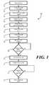
- FIG. 1illustrates one embodiment of a method in accordance with the invention.
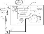
- FIG. 2illustrates one embodiment of a system in accordance with the invention.
- FIG. 3illustrates an alternate embodiment of a system in accordance with the invention.
- embodiments of the invention described hereinmay be comprised of one or more conventional processors and unique stored program instructions that control the one or more processors to implement, in conjunction with certain non-processor circuits, some, most, or all of the functions of load control as described herein.
- the non-processor circuitsmay include, but are not limited to, a radio receiver, a radio transmitter, signal drivers, clock circuits, power source circuits, and user input devices.
- an electrical service providersupplies the electrical load with power.
- the electrical loadreceives a communication signal from the electrical service provider when system operating conditions exceed at least one predetermined criterion.
- the communication signalmay comprise a one-way communication signal that is delivered from the electrical service provider to a control unit.
- the predetermined criterioncomprises line losses of an electrical distribution network coupled to the electrical load.
- the predetermined criterioncomprises ambient temperature.
- the predetermined criterionis where operating conditions are most vulnerable as determined by the electrical service provider.
- the power consumptionmay increase by to excessive use of air conditioners to cool homes. This power consumption may put a strain on the electrical service provider and/or the transmission and distribution networks.
- a regulation of power consumptionmay need to be administered.
- the electrical service providermay analyze ambient temperature, line losses, line capacities, and other associated power demand to may create a predetermined criterion based on the data.
- the predetermined criterion in this embodimentmay be a specific temperature where once the temperature is exceeded power demand may increase above desired levels, forcing power regulation.
- the electrical loadreceives the communication signal having measurement indicia.
- the measurement indiciamay comprise an indication to begin a base-line measurement of a power system characteristic.
- the power system characteristicmay comprise, but is not limited to, line voltage or frequency. These power system characteristics may be used to characterize the power usage of the electrical load.
- a base line measurementis performed at step 104 .
- the step of performing the base line measurementincludes measuring the power system characteristic for at least a predetermined time.
- the base line measurementoccurs proximately with the electrical load.
- a base line measurement where the power system characteristic is voltage occurring proximately with the electrical loadmay be a measurement of the output voltage received from a transmission or distribution network by a local electrical load.
- the base line measurementmay be taken over a predetermined time period.
- the time periodmay be a single time interval.
- the step of performing the base line measurementmay occur by measuring the power system characteristic for at least the predetermined time by taking at least a plurality of measurements of the power system characteristic. This plurality of measurements may be integrated or averaged.
- the base line measurement of a voltage characteristicmay be the average of a series of single voltage measurements taken over a long period of time.
- the base line measurement of a voltage characteristicmay be the average of continuous voltage measurements over a short period of time.
- the power system characteristicis processed across the predetermined time to obtain a processed base-line measurement.
- a differential factoris then retrieved or received at step 106 .
- the differential factormay be retrieved from a memory within a control unit coupled to the local electrical load.
- the differential factoris received along with the based line measurement initiation signal in the communication signal sent from the electrical service provider.
- the differential factoris then used to reduce the processed base line measurement to obtain a threshold value at step 107 .
- the step of reducing the processed base line measurement by the differential factorcomprises multiplying the processed base-line measurement by the differential factor.
- Another embodiment of reducing the processed base-line measurement by the differential factormay comprise subtracting the differential factor from the processed base-line measurement.
- the power system characteristicis monitored.
- the power system characteristicmay then be compared to the threshold value.
- a power characteristicis compared with the threshold value. Where the power system characteristic falls below the threshold value, at least one local electrical load is shed at step 110 . If the power system characteristic does not fall below the threshold value the power system characteristic may continue to be monitored.
- the step of shedding the at least one local electrical loadmay further comprise determining a prioritization of a plurality of loads, and removing the load having a highest priority.
- the plurality of loadsmay include high to low power consumption devices, wherein the high power consumption devices have the highest priority.
- the step of shedding the at least one local electrical loadmay comprise determining a prioritization of a plurality of loads, and removing the load having the lowest priority.
- priorityis determined by need of the load.
- a high priority loadmay include life a support systems while a low priority load may include a vending machine.
- a local electrical nodeis shed, the loads that will cause the least disturbances to the local environment will be shed.
- the power system characteristicis monitored again at step 111 .
- the power system characteristiccompared to the threshold value. If the power system characteristic is greater than the threshold value, the at least on local electrical load is actuated at step 113 . Allowing the actuating of shed local electrical loads may allow a dynamic system for shedding and actuating local electrical loads based on power demands.
- the at least one local electrical loadwhen the power system characteristic exceeds the threshold value by at least a predetermined restart value, the at least one local electrical load is actuated. In another embodiment of actuating additional loads following the shedding of a local electrical load, the at least one local electrical load is actuated when the power system characteristic exceeds the threshold value for at least a predetermined restart time.
- the hysteresis of these embodimentsmay eliminate variant fluctuations of the power system characteristic and may only allow actuation of a local electrical load when the power system characteristic consistently remains above the threshold value.
- the load controlling device 200comprises a receiver 203 .
- the receiver 203is in communication with an electrical services provider 204 .
- the electrical services provider 204may provide electrical power to the electrical load 201 .
- the electrical service provider 204may be in the form of a voltage source 202 as seen by the electrical load.
- the receiver 203is coupled to a controller 205 .
- the controller 205may further comprise a memory 206 .
- a power system characteristic measurement module 207may be operable with the controller 205 .
- the power system characteristic measurement module 207may be configured to establish a processed base-line measurement 208 of a power system characteristic 209 in response to the receiver 203 receiving a communication signal 210 .
- the communication signal 210may be sent over one other following technologies, but is not limited to satellite communication, WANs, WiFi Networks, and other similar networks.
- the electrical services provider 204may generate the communication signal 210 upon a predetermined threshold being exceeded.
- the predetermined threshold being exceededcomprises load losses of a power distribution grid 211 exceeding one of a predetermined load loss threshold.
- a further embodiment of the predetermined threshold being exceededmay include an ambient temperature exceeding a predetermined threshold.
- the communication signal 210may comprise measurement indicia 211 therein.
- the measurement indicia 211may comprise, but is not limited to the power system characteristic.
- the power system characteristic 209may comprise, but is not limited to, line voltage or frequency. The power system characteristic 209 may be used to characterize the power usage of the electrical load 201 .
- a threshold module 213is operable with the controller 205 .
- the threshold module 213may be configured to determine a threshold value 214 by retrieving from memory or receiving from a receiver a differential factor 215 .
- the differential factor 205may be retrieved from within the load controlling device 200 , perhaps from a non-volatile memory device.
- the differential factor 215is received along with the measurement indicia 211 in the communication signal sent from the electrical service provider 204 .
- the differential factor 215may be used to reduce the processed base-line measurement 208 .
- the differential factor 215reduces the processed base-line measurement 208 by multiplying the processed base-line measurement 208 by the differential factor 215 .
- Another embodiment of reducing the processed base-line measurement 208 by the differential factor 215may comprise subtracting the differential factor 215 from the processed base-line measurement 208 .
- the controller 205is coupled to a comparison module 216 .
- the comparison module 216may be configured to monitor the power system characteristic 207 .
- the comparison module 216may further be used to determine when the power system characteristic 207 falls below the threshold value 214 .
- a load shedding module 217is operable with the comparison module 216 .
- the load shedding module 217is configured to decouple power to at least the electrical load 201 . Power is decoupled from the electrical load 201 when the comparator module 216 indicates that the power system characteristic 209 has fallen below the threshold value 214 .
- the power system characteristic 209is the output voltage dropped over the electrical load.
- the power system characteristic 209is sent to the characteristic measurement module where a processed base-line measurement of the output voltage is established.
- the processed base-line measurement of the output voltageis next subtracted by the differential factor 215 to create an output voltage threshold value.
- the comparison module 216monitors the output voltage to determine if it drops over the output voltage threshold.
- the load controlling device 200comprises a restart module 218 .
- the restart module 218is connected to the comparison module 216 .
- the restart module 218may be configured to recouple power to the at least one electrical load 210 .
- Powermay be recoupled to at least one electrical load 201 when the comparator module 216 indicates that the power system characteristic 209 exceeds the threshold value 214 .
- the at least one electrical load 201when the power system characteristic 209 exceeds the threshold value 214 by at least a predetermined amount, the at least one electrical load 201 is actuated. In another embodiment of actuating additional loads following the shedding of a local electrical load, the at least one electrical load is actuated when the power system characteristic 209 exceeds the threshold value 214 for at least a predetermined restart time.
- the system for controlling power delivery 300may comprise a power distribution grid 301 having multiple nodes.
- the power distribution grid 301can include any power distribution system and variations to those familiar with the art.
- an electrical services provider 204is coupled to a first node 302 of the power distribution grid 301 .
- the electrical services provider 204may be capable of generating a communication signal 210 having measurement indicia therein.
- the at least one electrical load 201is coupled to a second node 303 of the power distribution grid 301 .
- a load controlling devicesmay further be coupled to the second node of the power distribution grid 301 .
Landscapes
- Engineering & Computer Science (AREA)
- Power Engineering (AREA)
- Remote Monitoring And Control Of Power-Distribution Networks (AREA)
- Supply And Distribution Of Alternating Current (AREA)
Abstract
Description
Claims (16)
Priority Applications (1)
| Application Number | Priority Date | Filing Date | Title |
|---|---|---|---|
| US11/470,549US7778737B2 (en) | 2005-09-07 | 2006-09-06 | Method and system for local load control |
Applications Claiming Priority (2)
| Application Number | Priority Date | Filing Date | Title |
|---|---|---|---|
| US71480105P | 2005-09-07 | 2005-09-07 | |
| US11/470,549US7778737B2 (en) | 2005-09-07 | 2006-09-06 | Method and system for local load control |
Publications (2)
| Publication Number | Publication Date |
|---|---|
| US20070129851A1 US20070129851A1 (en) | 2007-06-07 |
| US7778737B2true US7778737B2 (en) | 2010-08-17 |
Family
ID=37836389
Family Applications (1)
| Application Number | Title | Priority Date | Filing Date |
|---|---|---|---|
| US11/470,549Active2027-05-28US7778737B2 (en) | 2005-09-07 | 2006-09-06 | Method and system for local load control |
Country Status (2)
| Country | Link |
|---|---|
| US (1) | US7778737B2 (en) |
| WO (1) | WO2007030471A2 (en) |
Cited By (17)
| Publication number | Priority date | Publication date | Assignee | Title |
|---|---|---|---|---|
| US20100114393A1 (en)* | 2006-03-07 | 2010-05-06 | Dingguo Chen | Apparatus and method for predictive control of a power generation system |
| US20120303987A1 (en)* | 2011-05-27 | 2012-11-29 | Electronics And Telecommunications Research Institute | Energy control apparatus and method using property of electronic device |
| US20130197921A1 (en)* | 2012-02-01 | 2013-08-01 | Cellnet Innovations, Inc. | Methods and Systems for Requesting Compliance With a Requirement Over a Network |
| US20130238159A1 (en)* | 2007-11-16 | 2013-09-12 | University Of Strathclyde | Active network management |
| US8670224B2 (en) | 2011-11-04 | 2014-03-11 | Kohler Co. | Power management system that includes a membrane |
| US8942854B2 (en) | 2011-11-28 | 2015-01-27 | Kohler Co. | System and method for identifying electrical devices in a power management system |
| US9281716B2 (en) | 2011-12-20 | 2016-03-08 | Kohler Co. | Generator controller configured for preventing automatic transfer switch from supplying power to the selected load |
| US9293914B2 (en) | 2011-11-04 | 2016-03-22 | Kohler Co | Power management system that includes a generator controller |
| US9348381B2 (en) | 2011-10-19 | 2016-05-24 | Zeco Systems Pte Ltd | Methods and apparatuses for charging of electric vehicles |
| US20170122612A1 (en)* | 2013-10-29 | 2017-05-04 | Lennox Industries Inc. | Mixed air temperature sensor bypass |
| US9647495B2 (en) | 2012-06-28 | 2017-05-09 | Landis+Gyr Technologies, Llc | Power load control with dynamic capability |
| US9678162B2 (en) | 2011-11-04 | 2017-06-13 | Kohler Co. | Load control module that permits testing of power switching devices that are part of the load control module |
| US9841799B2 (en) | 2011-12-20 | 2017-12-12 | Kohler Co. | System and method for using a network to control a power management system |
| US9991709B2 (en) | 2011-11-04 | 2018-06-05 | Kohler Co. | Adding and shedding loads using load levels to determine timing |
| US10193381B2 (en) | 2016-09-27 | 2019-01-29 | Reliance Controls Corporation | Load management and switching devices and methods |
| US10199826B2 (en) | 2014-09-30 | 2019-02-05 | Mosaic Power, LLC | System and method for combining load response and energy storage for grid regulation |
| US10580094B1 (en) | 2013-08-07 | 2020-03-03 | Promanthan Brains LLC, Series Cold Futures only | Energy cost optimizer |
Families Citing this family (14)
| Publication number | Priority date | Publication date | Assignee | Title |
|---|---|---|---|---|
| GB2476396B (en)* | 2007-11-16 | 2011-12-21 | Univ Strathclyde | Active network management |
| GB2460504B (en)* | 2007-11-16 | 2011-07-20 | Univ Strathclyde | Active Network Management |
| FI121041B (en)* | 2007-11-20 | 2010-06-15 | Kone Corp | Power Supply Load Limitation |
| US8204632B2 (en)* | 2008-06-03 | 2012-06-19 | Electric Power Research Institute, Inc. | Emergency frequency load shedding scheme |
| GB2463548B8 (en) | 2008-09-22 | 2011-08-10 | Responsiveload Ltd | Smart responsive electrical load |
| US8744638B2 (en) | 2009-09-11 | 2014-06-03 | General Electric Company | Method and system for demand response in a distribution network |
| WO2011052956A2 (en)* | 2009-10-26 | 2011-05-05 | Lg Electronics Inc. | Network system and method of controlling the same |
| EP2354890B1 (en)* | 2010-01-25 | 2014-10-15 | Samsung Electronics Co., Ltd. | Method and apparatus for controlling operations of devices based on information regarding power consumption of the devices |
| EP2587734B1 (en) | 2010-06-26 | 2015-04-08 | LG Electronics Inc. | Network system |
| KR20120088465A (en)* | 2011-01-31 | 2012-08-08 | 삼성전자주식회사 | Washing machine and method for controlling the same |
| KR101745889B1 (en)* | 2011-01-31 | 2017-06-20 | 삼성전자주식회사 | Dryer and method for controlling the same |
| JP5422608B2 (en)* | 2011-06-10 | 2014-02-19 | 日立コンシューマエレクトロニクス株式会社 | Grid interconnection device |
| DE102013201116A1 (en)* | 2013-01-24 | 2014-07-24 | Krones Ag | Energy management for PET recycling plants |
| US10247436B2 (en)* | 2016-09-07 | 2019-04-02 | Solarcity Corporation | Systems and methods for controlling operations of a heating and cooling system |
Citations (53)
| Publication number | Priority date | Publication date | Assignee | Title |
|---|---|---|---|---|
| US4298935A (en) | 1979-10-05 | 1981-11-03 | Honeywell Information Systems Inc. | Interface circuit for coupling an automated maintenance system to a CPU |
| US4337401A (en) | 1981-01-23 | 1982-06-29 | Honeywell Inc. | Adaptive load shedding |
| US4347974A (en) | 1981-03-05 | 1982-09-07 | Honeywell, Inc. | Temperature control system with night setback programming as a function of temperature conditioning load |
| US4387763A (en) | 1981-09-14 | 1983-06-14 | Honeywell Inc. | Multistage thermostat using multirate integral action and exponential setpoint change |
| US4389577A (en) | 1982-04-14 | 1983-06-21 | Honeywell Inc. | Apparatus for power load-shedding with auxiliary commandable thermostat |
| US4413250A (en) | 1981-09-03 | 1983-11-01 | Beckman Instruments, Inc. | Digital communication system for remote instruments |
| US4435162A (en) | 1982-12-22 | 1984-03-06 | Schoenwald Justin P | Trigonometry visualizers and method of making same |
| US4583182A (en) | 1983-10-07 | 1986-04-15 | At&T Information Systems Inc. | Controllable risk parameter for device control system |
| US4616325A (en) | 1983-06-17 | 1986-10-07 | Johnson Service Company | Zone condition controller and method of using same |
| US4633217A (en) | 1984-06-04 | 1986-12-30 | Yamatake Honeywell | Communication apparatus |
| US4742475A (en) | 1984-06-19 | 1988-05-03 | Ibg International, Inc. | Environmental control system |
| US4753388A (en) | 1987-07-24 | 1988-06-28 | Robertshaw Controls Company | Duty-cycle controlling thermostat construction, system utilizing the same and method of making the same |
| US4776514A (en) | 1986-11-17 | 1988-10-11 | Honeywell Ltd. | Two wire line voltage thermostat |
| US4889179A (en) | 1987-11-25 | 1989-12-26 | J. R. Microwave, Inc. | Two wire adaptive system for interconnecting a four wire thermostat and a four wire, heating/cooling system |
| US5133302A (en) | 1990-09-18 | 1992-07-28 | Nissan Motor Co., Ltd. | Electric motor fan control system for vehicle |
| US5289362A (en) | 1989-12-15 | 1994-02-22 | Johnson Service Company | Energy control system |
| US5598349A (en) | 1994-10-25 | 1997-01-28 | Honeywell Inc. | Responding to pricing signals from a power supplier using mixed add/shed and profile setback delta schemes |
| US5635896A (en) | 1993-12-27 | 1997-06-03 | Honeywell Inc. | Locally powered control system having a remote sensing unit with a two wire connection |
| US5644173A (en) | 1994-10-25 | 1997-07-01 | Elliason; Kurt L. | Real time and/shed load based on received tier pricing and direct load control with processors for each load |
| US5731965A (en)* | 1996-06-21 | 1998-03-24 | Wisconsin Alumni Research Foundation | Power line harmonic reduction by hybrid parallel active/passive filter system with square wave inverter and DC bus control |
| US5761083A (en) | 1992-03-25 | 1998-06-02 | Brown, Jr.; Robert J. | Energy management and home automation system |
| US5816491A (en) | 1996-03-15 | 1998-10-06 | Arnold D. Berkeley | Method and apparatus for conserving peak load fuel consumption and for measuring and recording fuel consumption |
| US5926776A (en) | 1997-06-04 | 1999-07-20 | Gas Research Institute | Smart thermostat having a transceiver interface |
| US6108614A (en) | 1993-01-22 | 2000-08-22 | Diablo Research Corporation | System and method for serial communication between a central unit and a plurality of remote units |
| US6212894B1 (en) | 1996-03-29 | 2001-04-10 | Waterfurnace International Inc. | Microprocessor control for a heat pump water heater |
| US6254009B1 (en) | 1999-12-08 | 2001-07-03 | Carrier Corporation | Communicating thermostat |
| US6307464B1 (en) | 1999-12-20 | 2001-10-23 | Texas Instruments Incorporated | Method and apparatus using phases for communication in thermostat circuit |
| US6305611B1 (en) | 2000-06-15 | 2001-10-23 | Carrier Corporation | Setback tracking thermostat |
| US6320494B1 (en) | 2000-01-18 | 2001-11-20 | Honeywell International Inc. | Full duplex communication system with power transfer on one pair of conductors |
| US6480803B1 (en) | 2000-12-22 | 2002-11-12 | Carrier Corporation | Load shedding thermostat |
| US6478084B1 (en) | 1998-04-24 | 2002-11-12 | Steven Winter Associates, Inc. | Energy saving thermostat with a variable deadband |
| US6493644B1 (en)* | 1999-08-09 | 2002-12-10 | Power Measurement Ltd. | A-base revenue meter with power quality features |
| US6499533B2 (en) | 2000-05-25 | 2002-12-31 | Sumitomo Heavy Industries, Ltd. | Cooling disk unit for use in a wafer chucking device |
| US20030014200A1 (en)* | 1999-08-09 | 2003-01-16 | Power Measurement Ltd. | Revenue meter with power quality features |
| US6574581B1 (en) | 1994-10-25 | 2003-06-03 | Honeywell International Inc. | Profile based method for deriving a temperature setpoint using a ‘delta’ based on cross-indexing a received price-point level signal |
| US6608900B1 (en) | 1998-10-01 | 2003-08-19 | Marconi Communications, Inc. | Load management system for an electrical device |
| US6622097B2 (en) | 2001-06-28 | 2003-09-16 | Robert R. Hunter | Method and apparatus for reading and controlling electric power consumption |
| US6619555B2 (en) | 2002-02-13 | 2003-09-16 | Howard B. Rosen | Thermostat system communicating with a remote correspondent for receiving and displaying diverse information |
| JP2003262387A (en) | 2002-03-08 | 2003-09-19 | Hitachi Ltd | Air conditioner |
| US6622926B1 (en) | 2002-10-16 | 2003-09-23 | Emerson Electric Co. | Thermostat with air conditioning load management feature |
| US6634566B2 (en) | 2002-02-12 | 2003-10-21 | Carrier Corporation | Advanced setback reporting thermostat |
| US6643567B2 (en) | 2002-01-24 | 2003-11-04 | Carrier Corporation | Energy consumption estimation using real time pricing information |
| US6643566B1 (en) | 1999-01-12 | 2003-11-04 | Powerdsine Ltd. | System for power delivery over data communication cabling infrastructure |
| US6690939B1 (en) | 2000-09-18 | 2004-02-10 | Telefonaktiebolaget Lm Ericsson (Publ) | Increased radio communication capacity using transmit power balancing |
| US6718213B1 (en) | 2000-06-19 | 2004-04-06 | Electric City Corporation | Variable base load energy management system and method |
| US6798341B1 (en) | 1998-05-18 | 2004-09-28 | Leviton Manufacturing Co., Inc. | Network based multiple sensor and control device with temperature sensing and control |
| US6822555B2 (en) | 1999-11-15 | 2004-11-23 | General Electric Company | Fire system implemented with power line communications |
| US20050188706A1 (en) | 2004-01-15 | 2005-09-01 | Koichi Tokushige | Air conditioner and power line communication system |
| US6956463B2 (en) | 2002-10-02 | 2005-10-18 | Carrier Corporation | Method and apparatus for providing both power and communication over two wires between multiple low voltage AC devices |
| US7062361B1 (en) | 2000-05-02 | 2006-06-13 | Mark E. Lane | Method and apparatus for controlling power consumption |
| US7130719B2 (en)* | 2002-03-28 | 2006-10-31 | Robertshaw Controls Company | System and method of controlling an HVAC system |
| US7163158B2 (en) | 2004-12-14 | 2007-01-16 | Comverge, Inc. | HVAC communication system |
| US20070146958A1 (en)* | 2005-12-28 | 2007-06-28 | Babcock Paul M | Supply architecture for inductive loads |
Family Cites Families (1)
| Publication number | Priority date | Publication date | Assignee | Title |
|---|---|---|---|---|
| GB2301758A (en)* | 1995-06-03 | 1996-12-11 | Ibm | Icon driven data processing system |
- 2006
- 2006-09-06USUS11/470,549patent/US7778737B2/enactiveActive
- 2006-09-06WOPCT/US2006/034599patent/WO2007030471A2/enactiveApplication Filing
Patent Citations (56)
| Publication number | Priority date | Publication date | Assignee | Title |
|---|---|---|---|---|
| US4298935A (en) | 1979-10-05 | 1981-11-03 | Honeywell Information Systems Inc. | Interface circuit for coupling an automated maintenance system to a CPU |
| US4337401A (en) | 1981-01-23 | 1982-06-29 | Honeywell Inc. | Adaptive load shedding |
| US4347974A (en) | 1981-03-05 | 1982-09-07 | Honeywell, Inc. | Temperature control system with night setback programming as a function of temperature conditioning load |
| US4413250A (en) | 1981-09-03 | 1983-11-01 | Beckman Instruments, Inc. | Digital communication system for remote instruments |
| US4387763A (en) | 1981-09-14 | 1983-06-14 | Honeywell Inc. | Multistage thermostat using multirate integral action and exponential setpoint change |
| US4389577A (en) | 1982-04-14 | 1983-06-21 | Honeywell Inc. | Apparatus for power load-shedding with auxiliary commandable thermostat |
| US4435162A (en) | 1982-12-22 | 1984-03-06 | Schoenwald Justin P | Trigonometry visualizers and method of making same |
| US4616325A (en) | 1983-06-17 | 1986-10-07 | Johnson Service Company | Zone condition controller and method of using same |
| US4583182A (en) | 1983-10-07 | 1986-04-15 | At&T Information Systems Inc. | Controllable risk parameter for device control system |
| US4633217A (en) | 1984-06-04 | 1986-12-30 | Yamatake Honeywell | Communication apparatus |
| US4742475A (en) | 1984-06-19 | 1988-05-03 | Ibg International, Inc. | Environmental control system |
| US4776514A (en) | 1986-11-17 | 1988-10-11 | Honeywell Ltd. | Two wire line voltage thermostat |
| US4753388A (en) | 1987-07-24 | 1988-06-28 | Robertshaw Controls Company | Duty-cycle controlling thermostat construction, system utilizing the same and method of making the same |
| US4889179A (en) | 1987-11-25 | 1989-12-26 | J. R. Microwave, Inc. | Two wire adaptive system for interconnecting a four wire thermostat and a four wire, heating/cooling system |
| US5289362A (en) | 1989-12-15 | 1994-02-22 | Johnson Service Company | Energy control system |
| US5133302A (en) | 1990-09-18 | 1992-07-28 | Nissan Motor Co., Ltd. | Electric motor fan control system for vehicle |
| US5761083A (en) | 1992-03-25 | 1998-06-02 | Brown, Jr.; Robert J. | Energy management and home automation system |
| US6108614A (en) | 1993-01-22 | 2000-08-22 | Diablo Research Corporation | System and method for serial communication between a central unit and a plurality of remote units |
| US5635896A (en) | 1993-12-27 | 1997-06-03 | Honeywell Inc. | Locally powered control system having a remote sensing unit with a two wire connection |
| US20030187549A1 (en) | 1994-10-25 | 2003-10-02 | Honeywell Inc. | Profile based method for deriving a temperature setpoint using a 'delta' based on cross-indexing a received price-point level signal |
| US20060036350A1 (en) | 1994-10-25 | 2006-02-16 | Bohrer Philip J | Profile based method for deriving a temperature setpoint using a 'delta' based on cross-indexing a received price-point level signal |
| US5598349A (en) | 1994-10-25 | 1997-01-28 | Honeywell Inc. | Responding to pricing signals from a power supplier using mixed add/shed and profile setback delta schemes |
| US5644173A (en) | 1994-10-25 | 1997-07-01 | Elliason; Kurt L. | Real time and/shed load based on received tier pricing and direct load control with processors for each load |
| US6574581B1 (en) | 1994-10-25 | 2003-06-03 | Honeywell International Inc. | Profile based method for deriving a temperature setpoint using a ‘delta’ based on cross-indexing a received price-point level signal |
| US5816491A (en) | 1996-03-15 | 1998-10-06 | Arnold D. Berkeley | Method and apparatus for conserving peak load fuel consumption and for measuring and recording fuel consumption |
| US6212894B1 (en) | 1996-03-29 | 2001-04-10 | Waterfurnace International Inc. | Microprocessor control for a heat pump water heater |
| US5731965A (en)* | 1996-06-21 | 1998-03-24 | Wisconsin Alumni Research Foundation | Power line harmonic reduction by hybrid parallel active/passive filter system with square wave inverter and DC bus control |
| US5926776A (en) | 1997-06-04 | 1999-07-20 | Gas Research Institute | Smart thermostat having a transceiver interface |
| US6478084B1 (en) | 1998-04-24 | 2002-11-12 | Steven Winter Associates, Inc. | Energy saving thermostat with a variable deadband |
| US6798341B1 (en) | 1998-05-18 | 2004-09-28 | Leviton Manufacturing Co., Inc. | Network based multiple sensor and control device with temperature sensing and control |
| US6608900B1 (en) | 1998-10-01 | 2003-08-19 | Marconi Communications, Inc. | Load management system for an electrical device |
| US6643566B1 (en) | 1999-01-12 | 2003-11-04 | Powerdsine Ltd. | System for power delivery over data communication cabling infrastructure |
| US6493644B1 (en)* | 1999-08-09 | 2002-12-10 | Power Measurement Ltd. | A-base revenue meter with power quality features |
| US20030014200A1 (en)* | 1999-08-09 | 2003-01-16 | Power Measurement Ltd. | Revenue meter with power quality features |
| US6615147B1 (en)* | 1999-08-09 | 2003-09-02 | Power Measurement Ltd. | Revenue meter with power quality features |
| US6822555B2 (en) | 1999-11-15 | 2004-11-23 | General Electric Company | Fire system implemented with power line communications |
| US6254009B1 (en) | 1999-12-08 | 2001-07-03 | Carrier Corporation | Communicating thermostat |
| US6307464B1 (en) | 1999-12-20 | 2001-10-23 | Texas Instruments Incorporated | Method and apparatus using phases for communication in thermostat circuit |
| US6320494B1 (en) | 2000-01-18 | 2001-11-20 | Honeywell International Inc. | Full duplex communication system with power transfer on one pair of conductors |
| US7062361B1 (en) | 2000-05-02 | 2006-06-13 | Mark E. Lane | Method and apparatus for controlling power consumption |
| US6499533B2 (en) | 2000-05-25 | 2002-12-31 | Sumitomo Heavy Industries, Ltd. | Cooling disk unit for use in a wafer chucking device |
| US6305611B1 (en) | 2000-06-15 | 2001-10-23 | Carrier Corporation | Setback tracking thermostat |
| US6718213B1 (en) | 2000-06-19 | 2004-04-06 | Electric City Corporation | Variable base load energy management system and method |
| US6690939B1 (en) | 2000-09-18 | 2004-02-10 | Telefonaktiebolaget Lm Ericsson (Publ) | Increased radio communication capacity using transmit power balancing |
| US6480803B1 (en) | 2000-12-22 | 2002-11-12 | Carrier Corporation | Load shedding thermostat |
| US6622097B2 (en) | 2001-06-28 | 2003-09-16 | Robert R. Hunter | Method and apparatus for reading and controlling electric power consumption |
| US6643567B2 (en) | 2002-01-24 | 2003-11-04 | Carrier Corporation | Energy consumption estimation using real time pricing information |
| US6634566B2 (en) | 2002-02-12 | 2003-10-21 | Carrier Corporation | Advanced setback reporting thermostat |
| US6619555B2 (en) | 2002-02-13 | 2003-09-16 | Howard B. Rosen | Thermostat system communicating with a remote correspondent for receiving and displaying diverse information |
| JP2003262387A (en) | 2002-03-08 | 2003-09-19 | Hitachi Ltd | Air conditioner |
| US7130719B2 (en)* | 2002-03-28 | 2006-10-31 | Robertshaw Controls Company | System and method of controlling an HVAC system |
| US6956463B2 (en) | 2002-10-02 | 2005-10-18 | Carrier Corporation | Method and apparatus for providing both power and communication over two wires between multiple low voltage AC devices |
| US6622926B1 (en) | 2002-10-16 | 2003-09-23 | Emerson Electric Co. | Thermostat with air conditioning load management feature |
| US20050188706A1 (en) | 2004-01-15 | 2005-09-01 | Koichi Tokushige | Air conditioner and power line communication system |
| US7163158B2 (en) | 2004-12-14 | 2007-01-16 | Comverge, Inc. | HVAC communication system |
| US20070146958A1 (en)* | 2005-12-28 | 2007-06-28 | Babcock Paul M | Supply architecture for inductive loads |
Cited By (41)
| Publication number | Priority date | Publication date | Assignee | Title |
|---|---|---|---|---|
| US7957845B2 (en)* | 2006-03-07 | 2011-06-07 | Siemens Energy, Inc. | Apparatus and method for predictive control of a power generation system |
| US20100114393A1 (en)* | 2006-03-07 | 2010-05-06 | Dingguo Chen | Apparatus and method for predictive control of a power generation system |
| US8983666B2 (en)* | 2007-11-16 | 2015-03-17 | University Of Strathclyde | Active network management |
| US20130238159A1 (en)* | 2007-11-16 | 2013-09-12 | University Of Strathclyde | Active network management |
| US20120303987A1 (en)* | 2011-05-27 | 2012-11-29 | Electronics And Telecommunications Research Institute | Energy control apparatus and method using property of electronic device |
| US12175506B2 (en) | 2011-10-19 | 2024-12-24 | Zeco Systems Pte Ltd. | Systems and methods for charging of electric vehicles with charge balancing between multiple electric vehicle charging stations in a local area network |
| US10872361B2 (en) | 2011-10-19 | 2020-12-22 | Zeco Systems Pte Ltd. | Methods and apparatuses for charging of electric vehicles |
| US10210552B2 (en) | 2011-10-19 | 2019-02-19 | Zeco Systems Pte Ltd. | Methods and apparatuses for charging of electric vehicles |
| US11756086B2 (en) | 2011-10-19 | 2023-09-12 | Zeco Systems Pte Ltd. | Methods and systems for charging of electric vehicles |
| US11748788B2 (en) | 2011-10-19 | 2023-09-05 | Zeco Systems Pte Ltd. | Methods and systems for determining the availability of an electric vehicle charging station |
| US12190360B2 (en) | 2011-10-19 | 2025-01-07 | Zeco Systems Pte Ltd. | Systems and methods for charging of electric vehicles with charge balancing between multiple electric vehicle charging stations in a microgrid |
| US9348381B2 (en) | 2011-10-19 | 2016-05-24 | Zeco Systems Pte Ltd | Methods and apparatuses for charging of electric vehicles |
| US11715136B2 (en) | 2011-10-19 | 2023-08-01 | Zeco Systems Pte Ltd. | Methods and apparatuses for charging of electric vehicles |
| US11715138B2 (en) | 2011-10-19 | 2023-08-01 | Zeco Systems Pte Ltd. | Methods and systems for charging of electric vehicles |
| US11756087B2 (en) | 2011-10-19 | 2023-09-12 | Zeco Systems Pte Ltd. | Systems and methods for charging of electric vehicles with charge balancing between multiple electric vehicle charging stations |
| US10861066B2 (en) | 2011-10-19 | 2020-12-08 | Zeco Systems Pte Ltd. | Methods and apparatuses for charging of electric vehicles |
| US10846763B2 (en) | 2011-10-19 | 2020-11-24 | Zeco Systems Ptd Ltd. | Methods and apparatuses for charging of electric vehicles |
| US10169783B2 (en) | 2011-10-19 | 2019-01-01 | Zeco Systems Pte Ltd. | Methods and apparatuses for charging of electric vehicles |
| US10185977B2 (en) | 2011-10-19 | 2019-01-22 | Zeco Systems Pte Ltd. | Methods and apparatuses for charging of electric vehicles |
| US10185978B2 (en) | 2011-10-19 | 2019-01-22 | Zeco Systems Pte Ltd. | Methods and apparatuses for charging of electric vehicles |
| US10839433B2 (en) | 2011-10-19 | 2020-11-17 | Zeco Systems Pte Ltd. | Methods and apparatuses for charging of electric vehicles |
| US10192245B2 (en) | 2011-10-19 | 2019-01-29 | Zeco Systems Pte Ltd. | Methods and apparatuses for charging of electric vehicles |
| US10586258B2 (en) | 2011-10-19 | 2020-03-10 | Zeco Systems Pte Ltd. | Methods and apparatuses for charging of electric vehicles |
| US9293914B2 (en) | 2011-11-04 | 2016-03-22 | Kohler Co | Power management system that includes a generator controller |
| US9678162B2 (en) | 2011-11-04 | 2017-06-13 | Kohler Co. | Load control module that permits testing of power switching devices that are part of the load control module |
| US8670224B2 (en) | 2011-11-04 | 2014-03-11 | Kohler Co. | Power management system that includes a membrane |
| US9991709B2 (en) | 2011-11-04 | 2018-06-05 | Kohler Co. | Adding and shedding loads using load levels to determine timing |
| US10790664B2 (en) | 2011-11-04 | 2020-09-29 | Kohler Co. | Adding and shedding loads using load levels to determine timing |
| US8942854B2 (en) | 2011-11-28 | 2015-01-27 | Kohler Co. | System and method for identifying electrical devices in a power management system |
| US9841799B2 (en) | 2011-12-20 | 2017-12-12 | Kohler Co. | System and method for using a network to control a power management system |
| US9281716B2 (en) | 2011-12-20 | 2016-03-08 | Kohler Co. | Generator controller configured for preventing automatic transfer switch from supplying power to the selected load |
| US9118207B2 (en)* | 2012-02-01 | 2015-08-25 | Landis+Gyr Innovations, Inc. | Methods and systems for requesting compliance with a requirement over a network |
| US20130197921A1 (en)* | 2012-02-01 | 2013-08-01 | Cellnet Innovations, Inc. | Methods and Systems for Requesting Compliance With a Requirement Over a Network |
| US9647495B2 (en) | 2012-06-28 | 2017-05-09 | Landis+Gyr Technologies, Llc | Power load control with dynamic capability |
| US10902531B1 (en) | 2013-08-07 | 2021-01-26 | Promanthan Brains LLC | Predictive thermostat |
| US10657609B1 (en) | 2013-08-07 | 2020-05-19 | Promanthan Brains LLC, Series Cold Futures only | Smart switch with stochastic optimization |
| US10580094B1 (en) | 2013-08-07 | 2020-03-03 | Promanthan Brains LLC, Series Cold Futures only | Energy cost optimizer |
| US10571149B2 (en)* | 2013-10-29 | 2020-02-25 | Lennox Industries Inc. | Mixed air temperature sensor bypass |
| US20170122612A1 (en)* | 2013-10-29 | 2017-05-04 | Lennox Industries Inc. | Mixed air temperature sensor bypass |
| US10199826B2 (en) | 2014-09-30 | 2019-02-05 | Mosaic Power, LLC | System and method for combining load response and energy storage for grid regulation |
| US10193381B2 (en) | 2016-09-27 | 2019-01-29 | Reliance Controls Corporation | Load management and switching devices and methods |
Also Published As
| Publication number | Publication date |
|---|---|
| WO2007030471A3 (en) | 2007-10-04 |
| WO2007030471A2 (en) | 2007-03-15 |
| US20070129851A1 (en) | 2007-06-07 |
Similar Documents
| Publication | Publication Date | Title |
|---|---|---|
| US7778737B2 (en) | Method and system for local load control | |
| US8527107B2 (en) | Method and apparatus for effecting controlled restart of electrical servcie with a utility service area | |
| JP5671285B2 (en) | Method and system for demand response in a distribution network | |
| EP2639922B1 (en) | Operation planning method and operation planning device | |
| US8332666B2 (en) | Power management method and system | |
| US10033214B2 (en) | Power supply-demand adjusting apparatus, power system and power supply-demand adjusting method | |
| US8341442B2 (en) | Energy load management method and system | |
| EP2660942A1 (en) | Operation planning method and method for operating heat-pump hot-water supply heating system | |
| US20100217453A1 (en) | Grid Interconnection Device, Grid Interconnection System, And Power Control System | |
| WO2016120995A1 (en) | Water heater operation management device, water heater operation management system, and water heater operation management method | |
| WO2016002347A1 (en) | Power control system, method, and power control device | |
| KR20120016133A (en) | System and method for estimating and providing expedited operational reserve energy capacity using active load management | |
| KR101766797B1 (en) | System for controlling electric power for state variation minimization of electricity charge in Energy Storage System | |
| US8947066B2 (en) | Control apparatus | |
| JP6386064B2 (en) | Power management apparatus, power management method, and power management system | |
| US8121743B2 (en) | Power restoration management method and system | |
| KR20170002312A (en) | Adaptive energy management scheduling system and method for hybrid energy storage system with renewable energy resources | |
| US9912153B2 (en) | Method for controlling the ratio between supplied and drawn electric energy in an electric energy supply network | |
| WO2014185014A1 (en) | Management apparatus, device management method, and management system | |
| US10186864B2 (en) | Method of controlling the electrical regulation of an electrical installation as a function of curtailment settings | |
| JP2022054168A (en) | Power control device and power control method | |
| KR102152333B1 (en) | Electric power controlling system for optimizing State of Charge of Energy Storage System based on controlling Electric Vehicle charge and discharge | |
| KR102456609B1 (en) | Blockchain-based demand response contract method | |
| WO2019159904A1 (en) | Electric power control device, electric power control system, and electric power control method | |
| JP6827205B2 (en) | Group management system, power control device, power storage system |
Legal Events
| Date | Code | Title | Description |
|---|---|---|---|
| AS | Assignment | Owner name:COMVERGE, INC., NEW JERSEY Free format text:ASSIGNMENT OF ASSIGNORS INTEREST;ASSIGNORS:ROSSI, MR. JOHN F.;NG, MR. HOWARD;REEL/FRAME:018212/0370 Effective date:20060906 | |
| AS | Assignment | Owner name:SILICON VALLEY BANK, CALIFORNIA Free format text:SECURITY AGREEMENT;ASSIGNOR:COMVERGE, INC.;REEL/FRAME:021805/0291 Effective date:20081107 | |
| STCF | Information on status: patent grant | Free format text:PATENTED CASE | |
| AS | Assignment | Owner name:PARTNERS FOR GROWTH III, L.P., CALIFORNIA Free format text:SECURITY AGREEMENT;ASSIGNOR:COMVERGE, INC.;REEL/FRAME:025329/0577 Effective date:20101105 | |
| AS | Assignment | Owner name:GRACE BAY HOLDINGS II, LLC (AS SUCCESSOR-BY-ASSIGN Free format text:INTELLECTUAL PROPERTY SECURITY AGREEMENT;ASSIGNOR:COMVERGE, INC.;REEL/FRAME:027959/0286 Effective date:20120326 | |
| AS | Assignment | Owner name:PEAK HOLDING CORP., FLORIDA Free format text:INTELLECTUAL PROPERTY SECURITY AGREEMENT;ASSIGNOR:COMVERGE, INC.;REEL/FRAME:027968/0112 Effective date:20120326 | |
| AS | Assignment | Owner name:HERCULES TECHNOLOGY II, L.P., AS COLLATERAL AGENT, Free format text:SECURITY AGREEMENT;ASSIGNOR:COMVERGE, INC.;REEL/FRAME:029382/0849 Effective date:20121127 Owner name:COMVERGE, INC., GEORGIA Free format text:RELEASE BY SECURED PARTY (2008 FILING);ASSIGNOR:SILICON VALLEY BANK;REEL/FRAME:029382/0627 Effective date:20121127 | |
| AS | Assignment | Owner name:TRIANGLE CAPITAL CORPORATION, NORTH CAROLINA Free format text:SECURITY AGREEMENT;ASSIGNOR:COMVERGE, INC.;REEL/FRAME:029407/0981 Effective date:20121127 | |
| AS | Assignment | Owner name:COMVERGE, INC., GEORGIA Free format text:RELEASE BY SECURED PARTY;ASSIGNOR:HERCULES TECHNOLOGY II, L.P.;REEL/FRAME:030422/0550 Effective date:20130514 | |
| AS | Assignment | Owner name:COMVERGE, INC., GEORGIA Free format text:RELEASE BY SECURED PARTY FOR SECURITY INTEREST PREVIOUSLY RECORDED AT REEL 025329 FRAME 0577;ASSIGNOR:GRACE BAY HOLDINGS II, LLC, AS SUCCESSOR-BY-ASSIGNMENT TO PARTNERS FOR GROWTH III, L.P.;REEL/FRAME:030954/0746 Effective date:20130802 Owner name:COMVERGE, INC., GEORGIA Free format text:RELEASE BY SECURED PARTY OF SECURITY INTEREST PREVIOUSLY RECORDED AT REEL 027959 FRAME 0286;ASSIGNOR:GRACE BAY HOLDINGS II, LLC, AS SUCCESSOR-BY-ASSIGNMENT TO PARTNERS FOR GROWTH III, L.P.;REEL/FRAME:030954/0839 Effective date:20130802 | |
| AS | Assignment | Owner name:COMVERGE, INC., GEORGIA Free format text:RELEASE OF SECURITY INTEREST BY SECURED PARTY AS PREVIOUSLY RECORDED AT REEL 027968 FRAME 0112;ASSIGNOR:PEAK HOLDING CORP.;REEL/FRAME:031016/0115 Effective date:20130812 | |
| FPAY | Fee payment | Year of fee payment:4 | |
| AS | Assignment | Owner name:ITRON DISTRIBUTED ENERGY MANAGEMENT, INC., WASHING Free format text:MERGER AND CHANGE OF NAME;ASSIGNORS:ITRON DR/EE INC.;COMVERGE, INC.;REEL/FRAME:043618/0811 Effective date:20170601 | |
| AS | Assignment | Owner name:WELLS FARGO BANK, NATIONAL ASSOCIATION, NORTH CAROLINA Free format text:SECURITY INTEREST;ASSIGNORS:ITRON, INC.;ITRON NETWORKED SOLUTIONS, INC.;REEL/FRAME:045017/0893 Effective date:20180105 Owner name:WELLS FARGO BANK, NATIONAL ASSOCIATION, NORTH CARO Free format text:SECURITY INTEREST;ASSIGNORS:ITRON, INC.;ITRON NETWORKED SOLUTIONS, INC.;REEL/FRAME:045017/0893 Effective date:20180105 | |
| MAFP | Maintenance fee payment | Free format text:PAYMENT OF MAINTENANCE FEE, 8TH YEAR, LARGE ENTITY (ORIGINAL EVENT CODE: M1552) Year of fee payment:8 | |
| AS | Assignment | Owner name:ITRON, INC., WASHINGTON Free format text:MERGER AND CHANGE OF NAME;ASSIGNORS:ITRON DISTRIBUTED ENERGY MANAGEMENT, INC.;ITRON, INC.;ITRON, INC.;REEL/FRAME:045230/0691 Effective date:20171003 | |
| MAFP | Maintenance fee payment | Free format text:PAYMENT OF MAINTENANCE FEE, 12TH YEAR, LARGE ENTITY (ORIGINAL EVENT CODE: M1553); ENTITY STATUS OF PATENT OWNER: LARGE ENTITY Year of fee payment:12 |