US7778734B2 - Using energy-use sensors to model activity and location of building users - Google Patents
Using energy-use sensors to model activity and location of building usersDownload PDFInfo
- Publication number
- US7778734B2 US7778734B2US10/998,302US99830204AUS7778734B2US 7778734 B2US7778734 B2US 7778734B2US 99830204 AUS99830204 AUS 99830204AUS 7778734 B2US7778734 B2US 7778734B2
- Authority
- US
- United States
- Prior art keywords
- house
- appliances
- householder
- building
- energy use
- Prior art date
- Legal status (The legal status is an assumption and is not a legal conclusion. Google has not performed a legal analysis and makes no representation as to the accuracy of the status listed.)
- Expired - Lifetime
Links
- 230000000694effectsEffects0.000titleclaimsdescription13
- 238000010438heat treatmentMethods0.000claimsabstractdescription44
- 238000001816coolingMethods0.000claimsabstractdescription11
- 238000000034methodMethods0.000claimsdescription12
- 230000007717exclusionEffects0.000claims1
- 230000005611electricityEffects0.000abstractdescription34
- 238000012423maintenanceMethods0.000abstractdescription9
- 238000005259measurementMethods0.000abstractdescription9
- 238000005265energy consumptionMethods0.000abstractdescription8
- 230000001052transient effectEffects0.000description26
- 238000004891communicationMethods0.000description19
- 238000012544monitoring processMethods0.000description13
- 230000004044responseEffects0.000description11
- 230000036541healthEffects0.000description8
- 230000008901benefitEffects0.000description7
- 238000004458analytical methodMethods0.000description6
- 238000005406washingMethods0.000description6
- 238000013178mathematical modelMethods0.000description5
- 230000008859changeEffects0.000description4
- 230000000977initiatory effectEffects0.000description4
- 230000009471actionEffects0.000description3
- 238000004364calculation methodMethods0.000description3
- 238000010276constructionMethods0.000description3
- 230000002542deteriorative effectEffects0.000description3
- 238000005516engineering processMethods0.000description3
- 230000006870functionEffects0.000description3
- 230000009467reductionEffects0.000description3
- 238000004378air conditioningMethods0.000description2
- 230000004075alterationEffects0.000description2
- 238000009434installationMethods0.000description2
- 238000009413insulationMethods0.000description2
- 230000033001locomotionEffects0.000description2
- 239000000463materialSubstances0.000description2
- 230000008439repair processEffects0.000description2
- 238000009420retrofittingMethods0.000description2
- 230000003068static effectEffects0.000description2
- 238000012546transferMethods0.000description2
- 238000013459approachMethods0.000description1
- 230000005540biological transmissionEffects0.000description1
- 238000009529body temperature measurementMethods0.000description1
- 239000011449brickSubstances0.000description1
- 239000004566building materialSubstances0.000description1
- 230000015556catabolic processEffects0.000description1
- 238000004140cleaningMethods0.000description1
- 239000012141concentrateSubstances0.000description1
- 239000013078crystalSubstances0.000description1
- 238000006731degradation reactionMethods0.000description1
- 230000006866deteriorationEffects0.000description1
- 230000006872improvementEffects0.000description1
- 230000003993interactionEffects0.000description1
- 238000002307isotope ratio mass spectrometryMethods0.000description1
- 230000007774longtermEffects0.000description1
- 238000012067mathematical methodMethods0.000description1
- 238000012545processingMethods0.000description1
- 238000005086pumpingMethods0.000description1
- 230000005477standard modelEffects0.000description1
- 230000003442weekly effectEffects0.000description1
Images


Classifications
- G—PHYSICS
- G05—CONTROLLING; REGULATING
- G05B—CONTROL OR REGULATING SYSTEMS IN GENERAL; FUNCTIONAL ELEMENTS OF SUCH SYSTEMS; MONITORING OR TESTING ARRANGEMENTS FOR SUCH SYSTEMS OR ELEMENTS
- G05B15/00—Systems controlled by a computer
- G05B15/02—Systems controlled by a computer electric
- G—PHYSICS
- G05—CONTROLLING; REGULATING
- G05B—CONTROL OR REGULATING SYSTEMS IN GENERAL; FUNCTIONAL ELEMENTS OF SUCH SYSTEMS; MONITORING OR TESTING ARRANGEMENTS FOR SUCH SYSTEMS OR ELEMENTS
- G05B2219/00—Program-control systems
- G05B2219/20—Pc systems
- G05B2219/26—Pc applications
- G05B2219/2642—Domotique, domestic, home control, automation, smart house
Definitions
- the inventionrelates to the field of household energy management and in particular to ways in which the behaviour of the occupants of a house, the thermal properties of the house and the operation of household appliances can be measured and modelled, in order to control the household appliances in a certain way or to recommend courses of action to the users of the system such that energy use by the household is made more efficient.
- the words “house” and “household”are used for convenience but those words are not to be interpreted as limiting the scope of the invention to the context of separate, domestic dwellings.
- the word “house”is intended to include within its scope an apartment, an office, a hotel room or a part of any of the aforesaid.
- U.S. Pat. No. 5,572,438 by Ehlersdescribes a house system, which uses a first and a second microcomputer to monitor and control the energy in the household.
- the patentmainly describes the hardware required to deliver the improvements—microcomputer, current sensors, appliance control and communication links to the outside world.
- the systemrequires a current sensor on each appliance.
- the hardware requirements for this systemseem excessive and expensive to retrofit into an existing household.
- An electronic control system for a houseis currently on sale from Honeywell Controls under the registered trade mark Hometronic.
- the systemis described on their website.
- the Hometronic systemuses a single central controller to determine on and off times from appliances and heating appliances around the house. It can connect to the Internet and be controlled via the web from anywhere in the world. However, it relies on one control device being attached to one appliance to provide on/off control and this makes it an expensive system to retrofit.
- U.S. Pat. No. 5,115,967describes a mathematical method of predicting the transient thermal behaviour of a house climate control system (heating/cooling system).
- U.S. patent application Ser. No. 2002/0095269discloses an appliance monitoring system, in which a subsystem incorporated in each appliance monitors parameters such as the number of cycles and the energy consumption of the appliance. In the event that the appliance needs attention, the system alerts the user or a service centre.
- Microchip Technology Incis a supplier of microchips. They have posted an article entitled “Microchip watt-hour Meter using PIC16C923 and CS5460” on their website discussing how to use one of their chips to make a watt hour meter.
- the power measurement integrated circuit CS5460 from Cirrus Logic/Crystal Power Measurementis used with the microcontroller PIC16C923 to make a power meter.
- the CS5460measures the instantaneous voltage and current four thousand times per second and uses these measurements to compute instantaneous power, VRMS, IRMS and accumulated energy. Once the accumulated energy has increased by 10 Watt.seconds a pulse is generated at the output pin (EOUT pin) for counting by another device to form a consumption meter.
- the articleexplains how to use this device to record total power consumption.
- the inventionprovides a household energy management system comprising at least one sensor, which measures energy use by occupants of the house; a modelling means, which uses the energy measurements from the sensor to build a model of the behaviour of the occupants; and a controller, which controls the operation of one or more household appliances in the house on the basis of the model.
- the modelling meansmay build a predictive model of the pattern of behaviour of the occupants over time, in which case the predictive model may be continually refined in response to new measurements by the sensor.
- a model of the predicted behaviour of the occupants of a houseallows more efficient use of the appliances in the house.
- the predictive modelmay predict the times when the house will be occupied in order for the controller to control the operation of one or more household appliances, such as heating or cooling appliances, on the basis of the predicted times when the house will be occupied.
- the modelling meansmay build a temporary model of the current behaviour of the occupants.
- a model of the current behaviour of the occupants of a housealso allows more efficient use of the appliances in the house.
- the temporary modelmay allow the controller to control the operation of heating or cooling appliances to achieve a desired temperature according to the current level of activity of the occupants.
- the model of the behaviour of the occupantsmay include a determination of whether the house is occupied.
- the modelling meansmay have an interface with an intruder alarm system in the house and may receive signals indicative of the location of the occupants derived from, for example, a mobile phone network or a global positioning system.
- the modelling meanscan use the location signals to predict when the occupants may return to the house.
- One application of the behaviour modelling meansis to trigger an alert when an unexpected pattern of behaviour is detected. For example it may warn when an elderly person becomes immobile or when activity is detected in the house while the occupants are away.
- the senormeasures electrical activity within the house.
- the sensormay be a moveable sensor for location between an electricity supply outlet and an individual electrical appliance to measure the energy use by that appliance; or a fixed sensor on the household electricity supply to measure the respective energy uses of a plurality of electrical appliances connected to the supply.
- the optimum combinationis one fixed sensor and a few moveable sensors, as described below.
- the inventionprovides a household energy management system, comprising at least one sensor on the household electricity supply for measuring the instantaneous total power delivered by the electricity supply; means for identifying electrical appliances connected to the supply on the basis of their respective start-up characteristics when the appliances are switched on; means for comparing the sensed start-up characteristics with reference characteristics; and means for warning a user of the system when the sensed characteristics differ from the reference characteristics by more than a predetermined limit.
- the comparison meansmay further compare operating characteristics and/or shut down characteristics of the appliances with corresponding reference characteristics.
- the systemmay further comprise means for recording the total time of operation and/or the number of cycles of operation of each appliance, which can be compared against a database of lifetime expectancy and reliability for different appliances.
- the databasemay be a local database, internal to the system, or a shared database, accessed via an external network. In the case of a shared database, means are preferably provided for updating the shared database with measured lifetime and reliability data for appliances connected to the system.
- the systemmay further comprise modelling means receiving signals from the comparison means and from the database in order to recommend to the user of the system a program of maintenance or replacement of the appliance.
- the household energy management systemmay further comprise one or more temperature sensors for measuring the temperature inside the house; a source of information about the temperature outside the house; a modelling means, which uses the inside and outside temperature measurements to derive a transient thermal model of the house, which can predict changes in the inside temperature on the basis of the information about the outside temperature and on the basis of the operation of heating and/or cooling electrical appliances identified as connected to the supply; means for comparing the derived transient thermal model with a reference transient thermal model; and means for warning a user of the system of poor thermal properties of the house or of poor efficiency of the connected heating and/or cooling electrical appliances when the derived model differs from the reference model by more than a predetermined limit.
- the derived transient thermal modelmay be periodically updated and the reference transient thermal model may be a derived transient thermal model from an earlier period, whereby the warning means are for warning the user of the system of deteriorating thermal properties of the house or of deteriorating efficiency of the connected heating and/or cooling electrical appliances.
- a household energy management system in accordance with the inventionwhich monitors the energy consumption of household appliances, can also act as an electricity meter and may indicate the electricity consumption reading to the householder or transmit the reading directly to the electricity provider. If the system is networked to the electricity provider, then the provider can inform the system of changing electricity prices. The system may simply inform the user of these prices or it may be programmed to control household appliances so as to minimize the energy costs to the householder. For example, it may be more cost-effective to increase the background temperature of the house by operating electrical heating appliances at a time of day when electricity is relatively cheap in order to reduce the amount of heating required when demand is at its peak. Alternatively, the electricity provider may be given direct control of the electrical heating appliances.
- the suppliercan inform the system of changing gas prices.
- the systemmay simply inform the user of these prices or it may be programmed to control household gas appliances, such as a gas-fired central heating boiler, so as to minimize the energy costs to the householder.
- the energy management system or the gas supplier itselfmay be given direct control of the gas supply via an electrically-operated gas valve.
- modelling functions associated with any of the aspects of the inventionmay be carried out locally, by computing means provided as part of the system within the house; or remotely, by external computing means accessed via a telecommunications network.
- the systemallows for standard appliances to be used.
- Intelligent appliances containing communications and minicomputerscan be included but are not essential for this invention.
- the inventionconcentrates on using electrical sensors external to existing appliances and linking this to powerful analytical mathematical modelling.
- the overall system benefitsinclude:
- FIG. 1shows a first way of installing a single central sensor in accordance with the invention into a household electricity supply.
- FIG. 2shows a second way of installing a single central sensor in accordance with the invention into a household electricity supply.
- FIG. 3shows the communication links between the single central sensor and the other parts of the system according to the invention.
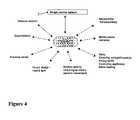
- FIG. 4shows various Internet services to which the system according to the invention may link.
- FIG. 5illustrates how the current in a household electricity supply may vary with time.
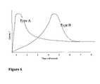
- FIG. 6illustrates the current start-up characteristics of two household appliances
- FIG. 7illustrates how the start-up characteristic of an appliance may change over time
- FIG. 8shows how a transient thermal model in accordance with the invention may be revised.
- FIG. 9shows how a transient thermal model in accordance with the invention may be used to control temperature with no feedback.
- the systemis intended not just to monitor the electrical system or the gas heating system but to link the monitoring of gas and electricity together to allow a whole system understanding to be achieved and provide better optimisation of the total energy use within the house. For example, sudden changes in electrical activity can indicate that the householder has returned home early from work and elicit a heating response within the controller to increase the house temperature.
- These sensorsinclude not only a single central sensor at the point of entry of electricity to the house but also adaptors, which plug into standard wall sockets.
- the adaptorsallow the collection of detailed information and control the appliances they are connected to.
- the analysisis performed on computers either local to the house or on the Internet. Communications between the various system items use standard known communication systems i.e. phone, radio, Internet or communication by power cable.
- the single central sensor( FIGS. 1 and 2 )
- the single central sensor 2 shown in FIG. 1is connected between the electric power cable to the house 4 and the house circuit breakers/distribution board 6 , or in other words at the electrical point of entry to the house.
- the sensor 8is used to monitor multiple devices. In more advanced versions, greater resolution may be possible by locating a sensor on each ring main out of the electricity meter, as shown in FIG. 2 .
- the single central sensor 2monitors the electrical power feeding into the house (e.g. current, voltage and power factor), stores appropriate data and analyses the data to determine what is happening with the house's appliances and with the occupants.
- the single central sensor 2contains electronic computing capability including storage (long and short term), processing power, battery back up (not shown) and communications capability with the wider network and local devices.
- FIG. 3illustrates in more detail the type of information that may be sent to and from the system over the Internet, as well as the sources and recipients of that information.
- the data acquiredwill be stored on a database. This will include data of appliance characteristics, times appliances are on and off and derived data. It can be stored either within the house in some form of small computer, perhaps as part of the single central sensor 2 , or on a more powerful server on the Internet-based network of computers.
- FIGS. 5 and 6Monitoring Appliance Use
- the systemcan determine the starting and stopping of appliances used in the house by monitoring the magnitude of current step changes.
- FIG. 5At time 10 minutes an electric light of current 1 Amp is turned on. Ten minutes later a heater of 3 Amp rating is turned on and at time 60 minutes the electric light is turned off. At this point in time the system knows that the light has been on for 50 minutes and knows its power and can therefore calculate the energy consumed by the light (kW.h). At the end of the day the system is able to summarise how much energy each of the house's appliances has used during the day. This can be provided as a summary to the householder such as on a web page or email.
- the actual type of appliance startedcan be determined by analysing the start-up characteristics. As shown in FIG. 6 , some appliances have quicker response characteristics than others. Type A and Type B have similar final operating currents but they differ in start-up characteristic. Type A has a quick peak in current, suggesting that it is a resistive load like a light bulb, which has a low resistance when cold but this resistance increases once it is hot and consequently the current falls. Type B takes longer to reach its peak current, perhaps indicating that it is a motor with a magnetic reluctance rather than a resistance and a starting inertia quite different to the type A appliance. The system can recognise the appliances by comparing them to a pre-programmed store of characteristics, which are loaded on the single central sensor 2 . These signature characteristics will be pre-programmed into the single central sensor 2 before installation in the house, so it can recognise what is being turned on and off. Alternatively the system can learn the signatures during use.
- the single central sensor systemmay identify that an ‘unknown appliance’ has been used and email the householder asking what the appliance is. By replying, the householder will teach the system to recognise the valve radio for next time.
- This new characteristiccan be used by the householder's system and also sent electronically to the other single central sensors on the Internet network for use in other houses.
- New versions of control softwarecan be sent to the single central sensor 2 through the network communications.
- This methodallows the system to learn in which room each appliance is kept. For example the 30 W radio might be in Bedroom 1 . This helps communications between householder and computer if the location of appliances is known. An initiation sequence like this is already described in US Patent Application 2003/0050737.
- the householderwill be able to access data records of appliance use and so will be able to inform the system of the whereabouts of any appliances that the system cannot directly deduce. So for example if the householder can see that the system did not correctly identify that a TV had been moved from the lounge to bedroom 1 the householder will be able to update this over the Internet interface (standard HTML web pages with radio buttons etc).
- An alternative way to teach the system to recognise appliancesis to include at least one moveable adaptor 10 as part of the system. This is an adaptor which fits between the appliance power plug and the fixed wall outlet.
- Itmay contain electronics that allow it to measure the current flowing into the appliance, in much the same way as the single central sensor 2 and communicate this to the single central sensor.
- the moveable adaptor 10may just include a transponder, which sends a simple signal to the single central sensor 2 informing it that current is flowing.
- the single central sensor 2can associate any transponder signals from the adaptor 10 with the instantaneous changes in household current already detected by the single central sensor 2 .
- the moveable plug adaptor 10will help with identification of identical appliances. For example, if two appliances are turned on at the same instant in time it may become difficult to determine what has happened. In general this can probably be ignored, as it is unlikely that appliances will turn on over the same millisecond and any errors introduced in this way will be a small part of the total electrical consumption.
- an adaptor 10with high consumption appliances so that more detailed data can be provided to the system. If, for example, a washing machine were fitted with one of these then the adaptor 10 would signal when current flows through it and the single central sensor 2 would know the difference between this appliance and other general appliances being turned on in the house.
- the adaptor 10could also be used to turn on and off the appliance, whereby the system could manage the appliance to run at night when electricity is cheaper.
- a further advantage of the moveable adaptor 10is that it can be moved to a different wall outlet. For example, if the system recognised and learned the behaviour of a refrigerator at the first outlet it could email the householder and request the householder to move the adaptor to a new outlet. The message might read: ‘At 18:06 this evening an appliance was turned on of 60 watts and the system can not determine what it is. Please move Mobile Adaptor 3 from current location on refrigerator to the outlet socket using this appliance and allow the system to learn the characteristics of this appliance. Thank you—Click here if you do not want another email reminder of this event.’
- a moveable adaptor 10Another advantage of using a moveable adaptor 10 is that it could recognise which appliances use significant electricity even when turned off or in standby mode. It is common for household appliances to use built in transformers, which use considerable energy heating the transformer even when the appliance is effectively turned off. The adaptor will inform the central monitor of power at all times and the system can then recognise that the appliance is consuming whilst in standby mode and send an email to the householder recommending that the appliance be disconnected from the mains when not in use.
- the adaptor 10could be fitted with additional devices to provide location information to the system. For example it could emit a radio signal which is used to triangulate its physical position in space. In this way the central detector could determine the physical location of appliances such as upstairs, 3 metres north, 1 metre east. In this way a detailed map of both the appliances and the location of a householder using an appliance can be pinpointed. This all helps to populate a detailed appliance database and improve communication between the system and householder.
- the systemcan use fewer special adaptors than the prior art systems which have permanently fixed adaptors.
- Analysing the stored datacan provide information on the householder's patterns of behaviour. It will be possible to observe patterns of behaviour over a weekly basis. For example, the system can notice that every Tuesday the television is switched on at the same time of day and notice on Fridays that the householder gets home 2 hours later than on other workdays. Having detected these patterns of behaviour, the system can alter the control of appliances to provide improved comfort and cost to the householder. This is particularly useful in optimising high energy-consuming appliances such as heating and air conditioning. So on the days that the householder is expected home late the system can defer heating the house to its full temperature until just before the householder is expected.
- the systemcan detect the instantaneous behaviour at any one instant and this can be used to modify the energy control parameters.
- Appliancesare generally turned on when an occupant of the house presses a switch.
- the systemcan use this to determine what activity is taking place within the house.
- the behaviour modelcan probably deduce how many occupants are in the house, where they are and a rough idea of what they are doing. This could be used to
- the single central sensor systemcan alter the control temperature of the house if the householder is obviously active or has gone out.
- the activity level of the householdercan be inferred from the appliances detected within the house. For example, if the householder is using the vacuum cleaner the system might decide to reduce the control temperature within the house until the cleaning has stopped. A reduction in temperature can both reduce the energy consumed by the house and also make the environment more comfortable for the householder whilst they are exercising with the vacuum cleaner. On the other hand, if the system knows that only one person lives in the house and has noticed that the TV is switched on, it may be reasonable to deduce that the householder is static and a slight increase in house temperature would be more comfortable. If two people are in the house then a gated logic decision is required in the control functions to ensure the warmest state is chosen (e.g. the temperature is warmed for a static person even if other one is using the vacuum cleaner)
- the systemcan deduce that all occupants of the house are out and lower the house temperature.
- a special transpondercould be included in the burglar alarm to communicate directly with the single central sensor to inform it that the alarm is set and all occupants are out of the house.
- the position and movement of the householdercan be noted from the householder's mobile phone and the location detected by the phone network. If the wider system includes access to the mobile phone network then the distance of the householder from their home can be determined and if the householder is far away then the house temperature can be lowered. For example if the transient model says the house can be heated up to full temperature within 30 minutes and the householder is known to be more than 30 minutes away then the heating system can be turned off completely.
- Location informationcould also be provided based on other monitored activities of the householder. For example, if the householder is using a computer at his/her workplace, then that computer or an Internet service provider could relay the householder's location to the household energy management system.
- the systemcould also be networked with other locating systems, such as a congestion charging system that would monitor the location of the householder's car.
- the household temperaturecan be linked to the activity of the householder and his actual location rather than being linked to a time clock as with current house heating systems.
- the systembuilds up and records detailed energy consumption data and by integrating this over time it can record the total energy (kW.h) used and so become an energy meter. This allows billing information to be sent to the customer and the utility directly over the communications network, as shown in FIG. 4 .
- This variable tariff systemcould become quite sophisticated offering different rates over the course of one day and different rates from day to day.
- the customercould be kept informed of these tariffs over the Internet interface available through the total networked system or through daily emailed updates of any rate changes.
- the systemcan identify when the householder operates high consumption appliances and may benefit by altering the time of operating these appliances—e.g. turning the washing machine on at a night when electricity is cheaper.
- the system describedcan be integrated to communicate directly with the supplier of energy.
- a featurecan be included, which allows the electricity supplier to turn appliances on and off to smooth the peak demand which occurs on the grid network. The householder would benefit through a price reduction under such an arrangement.
- the gas suppliercan control the gas heating of a house. For example, on the coldest winter days the gas supplier knows that demand is going to peak at its highest level of the year and may not have the capacity to pass enough gas down the pipelines to meet demand. With the proposed system it is possible for the networked houses to have heating turned on a few hours early such that the house is pre-warmed before peak demand time. Although this is likely to increase the total gas consumption it will reduce the peak demand later in the day and has this operational benefit to the gas supplier who can avoid building additional gas transmission pipelines and pumping equipment. The customer can be encouraged to buy into this scheme through improved annual prices.
- the single central sensor 2 located at the point of electrical entry to the housecan be used to monitor the quality of electricity supplied to the building. In this way it can monitor not only total loss of power during power cuts and its duration but also alterations in frequency, brief spikes of power, dips in voltage. This information can be useful to the householder in monitoring the quality of electricity supplied. If the electricity does not meet requirements, the householder has the opportunity of demanding compensation or improvements from the supplier with the evidence provided by the single central sensor 2 . Communication could again be achieved through the Internet, such as web page access or email.
- the systemcan be used to compare the start-up characteristics of each appliance on a day-by-day basis. In this way the system can monitor the health of the householder's appliances and warn of problems.
- an electric motor in a washing machinemay have a start-up characteristic when new of Type B, as shown in FIG. 7 .
- the characteristic of the motorwill change as the motor ages and the bearings stiffen and the brushes wear. Towards the end of normal life, the brushes may arc and the motor will take longer and/or require more current to reach speed.
- the analysis softwarecan detect these changed characteristics (such as a move to characteristic Type B x ) and compare them to known acceptable behaviour. If the appliance falls outside predetermined limits then an alarm (e.g. an email/text message) can be sent to either the householder or a maintenance technician who can arrive and fix the motor before it fails. Early warning like this provides the householder with preventative maintenance, which reduces the inconvenience and cost of unexpected failures.
- the single central sensorcould monitor for arcing across the brushes of a motor and to include this function it would monitor for electrical noise during continuous operation, and not just the motor start-up characteristics.
- the systemwill be able to carry out optimisation calculations and recommend to the householder whether an appliance is worth repairing or is best replaced. For example, it may calculate that the washing machine, which is about to fail, has a high probability of further failures (based on a database of typical failure rates). It may find that the cost of two repairs in succession combined with say improved energy consumption of the latest appliance would mean that the householder would be best to replace the appliance rather than repair it. An appropriate message can be sent to the customer with or without an option to buy a replacement appliance through the system. This sort of calculation could be quite detailed including interest rates, probability of failure rates and details on spare parts costs, a database of known appliances and their life expectancies. It offers an online optimisation cost calculation, which is not currently feasible to a householder.
- a further appliance health monitoring methodis available through counting the number of cycles and hours of operation an appliance has completed. In this way any appliance can be monitored for life consumed and an estimate made of remaining life based on a database of typical expected lifetimes for appliances such as fridges, freezers, cookers or heating boilers. This database could even include model specific data for improved accuracy.
- This databasewould be useful as a way of evaluating the value of different appliances and recommending longer-lived appliances for householders to buy.
- a transient thermal model of the housecan be generated and validated by the system. It can be used to:
- a transient thermal model of the house heatingis a mathematical model of the house heating characteristics including terms for the steady state heat loss and also terms for its transient thermal performance. For example, a heavy, brick built house will take longer to heat up and cool down than a lightweight, wooden/fibreboard construction and terms in the mathematical model are included for mass, thickness and specific heat of materials etc.
- the heatingis turned on and the actual temperature rises (as shown by Line 1 ) until it reaches the control temperature at its peak and the heating is turned off. From here the temperature falls according to Line 2 until the minimum temperature is recorded and the heating is started up again.
- the single central sensor 2will detect the time points when the maximum and minimum temperatures are reached and it can compare the actual times to the mathematically predicted response. Differences in these two will demand the software changes the coefficient terms in the model until the best fit with all known data is achieved. For the first few days the system may be inaccurate, but later once a larger database of known heating and cooling times is known the mathematical model will become increasingly accurate.
- the systemcan use network data to improve validity. For example it can be informed of local weather from existing Internet weather databases which have weather information from nearby weather stations.
- the householderuses a time controller to define when the heating (or air conditioning) should turn on and off.
- the householdercan now define when the house is to reach the controlled temperature schedule rather than when to start heating. This allows the single central sensor system to calculate the optimum time to turn on. For example, say the householder returns home at 17:30 in the evening and wants the house at the desired temperature at 17:30.
- the systemcan use the transient model to calculate the time it will take to reach the desired temperature: on a cold windy day this might be 1 hour and on a mild day it might be 30 minutes. In this way the heating system is turned on for the minimum time and the house consumes the minimum heat energy.
- the transient thermal modelcan be used to provide a crude control system without referring to the house thermocouple temperature sensor. This would allow the system to control to a reduced temperature (Line 2 ) without alteration to the existing thermostat fitted to an existing house heating system, which is set at a higher temperature (Line 1 ).
- FIG. 9shows how this would happen.
- the transient modelwould be used to determine how fast the house heats up and cools down and the heating appliance (such as a gas boiler) would be turned on and off in response to the mathematical prediction of internal temperature in order to maintain the temperature close to a desired average. This does not require a house thermocouple for feedback, which means it would have a tendency to drift in temperature, as seen in the slope of Line 2 in FIG. 9 . This is unacceptable in the long term but may serve for short periods when temperatures below the house thermostat set point are required.
- the validated thermal transient modelcan be used to compare the house to national house norms. In this way the thermal characteristics of the house can be compared to acceptance limits and weaknesses in the house thermal characteristics can be identified and remedied. For example the system may notice that the house cools down unusually quickly on windy days and yet has a normal cooling characteristic under still air conditions. This will indicate that the house is susceptible to wind and is therefore draughty. An email could be sent to the householder or maintenance contractor to investigate and remedy the situation.
- thermal transient modelcan be compared in this manner and the house can be evaluated including the specific heat properties of building materials. Energy saving measures that are recommended in this way are thus based on actual measurements of the house characteristics, rather than generic recommendations which are given to all householders.
- the transient thermal modelcan be used to determine the operational health of the heating system within the house. As explained previously, the system will continuously adjust coefficients within the transient thermal model to ensure it aligns with the true house thermal response. Over months of operation, these coefficients will drift as the thermal characteristics of the house worsen with age. This will be most noticeable with a heating boiler as it becomes fouled through use—the house will begin to take longer to heat up. This gradual drift in characteristics can be used to monitor the degradation of the heating boiler and when a predetermined limit is met then maintenance action can be recommended to the householder or service provider. This active monitoring of boiler health will provide the householder with more optimal expenditure on maintenance, rather than just maintaining the boiler annually when it may still be in good condition.
- a special house thermostatthat communicates with the single central sensor 2 can be used. This thermostat acts as a normal house thermostat—switching open and closed as the temperature rises and falls through set limits. However, it communicates this to the single central sensor 2 so that the system can still determine when temperature limits are reached and the transient thermal model can still be aligned with the real thermal response.
- the system describedis capable of making decisions for the householder on a minute by minute basis. Initially it will do this in a pre-programmed way—making assumptions about house temperature and timings that are best estimates. However, the system needs a method of improving, learning and adapting to the particular householder's preferences. The householder can do this by informing the system as to whether the result is acceptable. For example, if the householder finds the temperature one day to be too cool in the morning, the householder could open a web page interface window on the system's Internet interface and click appropriate pages to instruct the system that the wrong response was achieved. The more this is done the more the system will adapt to the actual preferences of the user.
Landscapes
- Engineering & Computer Science (AREA)
- General Engineering & Computer Science (AREA)
- Physics & Mathematics (AREA)
- General Physics & Mathematics (AREA)
- Automation & Control Theory (AREA)
- Selective Calling Equipment (AREA)
- Telephonic Communication Services (AREA)
- Remote Monitoring And Control Of Power-Distribution Networks (AREA)
- Management, Administration, Business Operations System, And Electronic Commerce (AREA)
Abstract
Description
- Reduced energy consumption.
- Improved householder comfort.
- Improved maintenance and utilisation of expensive capital appliances in the house.
- Reduced cost to the householder through improved energy tariffs.
- Recommending energy saving measures to the householder based on actual measurements of the householder's behaviour, the thermal efficiency of the house and the operational efficiency of household appliances.
- All appliances used in the house and their pattern of use
- The house's transient thermal behaviour under heating and cooling conditions
- Turn all household appliances off
- Turn all appliances in
Bedroom 1 on - Turn all appliances off
Bedroom 2 all on- Turn all appliances off
Bedroom 3 all on- Turn all appliances off
- Kitchen all on
- Turn all appliances off
- Living room all on
- Etc
- control the temperature of the room the occupants are in. Other rooms could be heated to a lower temperature (if individual room temperature control is available).
- recognize a sudden change of behaviour such as an unexpected reduction in activity of an elderly or infirm person. The change in behaviour pattern can be used to email a warning to a nearby relative.
- Determine when the heating should be turned on and off and so optimise the use of the heat consumed.
- Carry out health monitoring of the heating/insulation systems and recommend maintenance actions.
- Compare the house to other houses or standard models of average houses
- Heat transfer coefficient inside house.
- Heat transfer coefficient outside house—terms including effect of wind, rain, humidity etc.
- Temperature inside.
- Temperature outside.
- Materials of construction including thickness, thermal insulation qualities, mass, specific heat.
- Wind resistance of apertures such as doors and windows.
Claims (4)
Priority Applications (2)
| Application Number | Priority Date | Filing Date | Title |
|---|---|---|---|
| US12/843,756US8600562B2 (en) | 2003-11-27 | 2010-07-26 | Household energy management sytem |
| US13/016,990US8386082B2 (en) | 2003-11-23 | 2011-01-29 | Utilizing cell phone location for occupancy determination and home energy control |
Applications Claiming Priority (2)
| Application Number | Priority Date | Filing Date | Title |
|---|---|---|---|
| GB0327583.1 | 2003-11-27 | ||
| GB0327583AGB2408592B (en) | 2003-11-27 | 2003-11-27 | Household energy management system |
Related Child Applications (1)
| Application Number | Title | Priority Date | Filing Date |
|---|---|---|---|
| US12/843,756ContinuationUS8600562B2 (en) | 2003-11-23 | 2010-07-26 | Household energy management sytem |
Publications (2)
| Publication Number | Publication Date |
|---|---|
| US20050171645A1 US20050171645A1 (en) | 2005-08-04 |
| US7778734B2true US7778734B2 (en) | 2010-08-17 |
Family
ID=29797918
Family Applications (3)
| Application Number | Title | Priority Date | Filing Date |
|---|---|---|---|
| US10/998,302Expired - LifetimeUS7778734B2 (en) | 2003-11-23 | 2004-11-26 | Using energy-use sensors to model activity and location of building users |
| US12/843,756Expired - LifetimeUS8600562B2 (en) | 2003-11-23 | 2010-07-26 | Household energy management sytem |
| US13/016,990Expired - LifetimeUS8386082B2 (en) | 2003-11-23 | 2011-01-29 | Utilizing cell phone location for occupancy determination and home energy control |
Family Applications After (2)
| Application Number | Title | Priority Date | Filing Date |
|---|---|---|---|
| US12/843,756Expired - LifetimeUS8600562B2 (en) | 2003-11-23 | 2010-07-26 | Household energy management sytem |
| US13/016,990Expired - LifetimeUS8386082B2 (en) | 2003-11-23 | 2011-01-29 | Utilizing cell phone location for occupancy determination and home energy control |
Country Status (2)
| Country | Link |
|---|---|
| US (3) | US7778734B2 (en) |
| GB (1) | GB2408592B (en) |
Cited By (42)
| Publication number | Priority date | Publication date | Assignee | Title |
|---|---|---|---|---|
| US20070203860A1 (en)* | 2006-02-24 | 2007-08-30 | Gridpoint, Inc. | Energy budget manager |
| US20090083167A1 (en)* | 2007-09-24 | 2009-03-26 | Budderfly Ventures, Llc | Computer based energy management |
| US20090143875A1 (en)* | 2007-11-30 | 2009-06-04 | Kabushiki Kaisha Toshiba | Action evaluation apparatus and method |
| US20090299504A1 (en)* | 2008-05-28 | 2009-12-03 | Kabushiki Kaisha Toshiba | Appliance control apparatus and method |
| US20100045470A1 (en)* | 2008-07-31 | 2010-02-25 | Araiza Steven P | Steam distribution control system and method for a steam heating system |
| US20100106674A1 (en)* | 2009-04-30 | 2010-04-29 | Mclean Donald John | Method and system for integrated analysis |
| US20100241284A1 (en)* | 2007-11-20 | 2010-09-23 | Yuko Maeda | Energy management system |
| US20100286937A1 (en)* | 2009-05-08 | 2010-11-11 | Jay Hedley | Building energy consumption analysis system |
| US20120232702A1 (en)* | 2011-03-11 | 2012-09-13 | Honeywell International Inc. | Setpoint optimization for air handling units |
| US20120259476A1 (en)* | 2010-09-29 | 2012-10-11 | Sears Brands, Llc | Energy management unit with diagnostic capabilities |
| US20130076528A1 (en)* | 2011-09-27 | 2013-03-28 | General Electric Company | Health monitoring system utilizing service consumption data |
| US8452457B2 (en)* | 2011-10-21 | 2013-05-28 | Nest Labs, Inc. | Intelligent controller providing time to target state |
| US20130340450A1 (en)* | 2012-06-20 | 2013-12-26 | Whirlpool Corporation | On-line energy consumption optimization adaptive to environmental condition |
| US20140114484A1 (en)* | 2012-03-09 | 2014-04-24 | Panasonic Corporation | Appliance control method, appliance control apparatus, control server, and control terminal |
| US20140125150A1 (en)* | 2012-11-08 | 2014-05-08 | Green Edge Technologies, Inc. | Systems, devices, and methods for automation and energy management |
| US8738195B2 (en)* | 2010-09-21 | 2014-05-27 | Intel Corporation | Inferencing energy usage from voltage droop |
| USRE45574E1 (en) | 2007-02-09 | 2015-06-23 | Honeywell International Inc. | Self-programmable thermostat |
| US20150185751A1 (en)* | 2013-12-26 | 2015-07-02 | Lutron Electronics Co., Inc. | Load-sensing remote control device for use in a load control system |
| US9104211B2 (en) | 2010-11-19 | 2015-08-11 | Google Inc. | Temperature controller with model-based time to target calculation and display |
| US9115908B2 (en) | 2011-07-27 | 2015-08-25 | Honeywell International Inc. | Systems and methods for managing a programmable thermostat |
| US9423432B2 (en) | 2013-12-20 | 2016-08-23 | Thomson Licensing | Tracking electrical appliance usage |
| US20170082994A1 (en)* | 2015-09-21 | 2017-03-23 | International Business Machines Corporation | Attribute Energy Consumption Through Power Sensing and User Localizations |
| WO2017052724A1 (en)* | 2015-09-25 | 2017-03-30 | Intel Corporation | Utility provisioning with iot analytics |
| CN106896731A (en)* | 2015-12-18 | 2017-06-27 | 英业达科技有限公司 | The devices and methods therefor of household electrical appliances behaviour in service is shown according to user's position control |
| US9699871B2 (en) | 2013-03-14 | 2017-07-04 | Lutron Electronics Co., Inc. | State change devices for switched electrical receptacles |
| US9702582B2 (en) | 2015-10-12 | 2017-07-11 | Ikorongo Technology, LLC | Connected thermostat for controlling a climate system based on a desired usage profile in comparison to other connected thermostats controlling other climate systems |
| WO2017146402A1 (en)* | 2016-02-24 | 2017-08-31 | Samsung Electronics Co., Ltd. | Server and method of controlling user environment by server |
| US9817045B2 (en) | 2010-12-13 | 2017-11-14 | Fraunhofer Usa, Inc. | Methods and system for nonintrusive load monitoring |
| US9848479B2 (en) | 2013-12-26 | 2017-12-19 | Lutron Electronics Co., Inc. | Faceplate remote control device for use in a load control system |
| US9921554B2 (en) | 2007-09-24 | 2018-03-20 | Budderfly, Inc. | Computer based energy management |
| US10001792B1 (en)* | 2013-06-12 | 2018-06-19 | Opower, Inc. | System and method for determining occupancy schedule for controlling a thermostat |
| US10006642B2 (en) | 2014-05-09 | 2018-06-26 | Jerritt L. Gluck | Systems and methods for controlling conditioned fluid systems in a built environment |
| US10371400B2 (en)* | 2013-11-04 | 2019-08-06 | Ademco Inc. | Remote contractor system with site specific energy audit capability |
| US10380705B2 (en) | 2013-10-30 | 2019-08-13 | Carrier Corporation | System and method for modeling of target infrastructure for energy management in distributed-facilities |
| US10488062B2 (en) | 2016-07-22 | 2019-11-26 | Ademco Inc. | Geofence plus schedule for a building controller |
| US10534331B2 (en) | 2013-12-11 | 2020-01-14 | Ademco Inc. | Building automation system with geo-fencing |
| US10747242B2 (en) | 2010-11-19 | 2020-08-18 | Google Llc | Thermostat user interface |
| US10806010B2 (en) | 2013-12-26 | 2020-10-13 | Lutron Technology Company Llc | Control device for use with a three-way lamp socket |
| US10911257B2 (en) | 2009-08-18 | 2021-02-02 | Ademco Inc. | Context-aware smart home energy manager |
| US20210123771A1 (en)* | 2019-10-29 | 2021-04-29 | Martha Patricia Vega | Methods, systems, apparatuses and devices for optimizing utility consumption associated with at least one premises |
| US20210274000A1 (en)* | 2012-12-13 | 2021-09-02 | Google Llc | Synchronization of appliances to a schedule of a user |
| US11409315B2 (en)* | 2008-09-30 | 2022-08-09 | Google Llc | Systems, methods and apparatus for encouraging energy conscious behavior based on aggregated third party energy consumption |
Families Citing this family (157)
| Publication number | Priority date | Publication date | Assignee | Title |
|---|---|---|---|---|
| US7744008B2 (en) | 2004-01-08 | 2010-06-29 | Robertshaw Controls Company | System and method for reducing energy consumption by controlling a water heater and HVAC system via a thermostat and thermostat for use therewith |
| US7469550B2 (en) | 2004-01-08 | 2008-12-30 | Robertshaw Controls Company | System and method for controlling appliances and thermostat for use therewith |
| ES2388067T3 (en)* | 2005-10-18 | 2012-10-08 | Carrier Corporation | System and method to control the operation of a heat pump and supplementary heating |
| GB2432016B (en)* | 2005-11-04 | 2007-12-05 | Univ Montfort | Electronic Control Units for Central Heating Systems |
| US20070225871A1 (en)* | 2006-03-24 | 2007-09-27 | Karstens Christopher K | Managing predictable thermal environments |
| JP5114026B2 (en)* | 2006-06-28 | 2013-01-09 | 三洋電機株式会社 | Demand control device |
| CN101578504B (en)* | 2006-12-28 | 2012-01-11 | 松下电器产业株式会社 | Flowmeter and gas supply system |
| US20080183307A1 (en)* | 2007-01-26 | 2008-07-31 | Autani Corporation | Upgradeable Automation Devices, Systems, Architectures, and Methods |
| ATE412936T1 (en)* | 2007-02-08 | 2008-11-15 | Nordiq Goeteborg Ab | HEATING SYSTEM CONTROL BASED ON REQUIRED HEATING POWER |
| GB2448896B (en)* | 2007-05-02 | 2009-05-20 | Univ Montfort | Energy management system |
| US7701328B2 (en)* | 2007-08-27 | 2010-04-20 | Dan Wall | Alarm management using source attributes |
| US8019567B2 (en) | 2007-09-17 | 2011-09-13 | Ecofactor, Inc. | System and method for evaluating changes in the efficiency of an HVAC system |
| JP2009130986A (en)* | 2007-11-20 | 2009-06-11 | Panasonic Electric Works Co Ltd | Energy management system |
| US20110061014A1 (en) | 2008-02-01 | 2011-03-10 | Energyhub | Interfacing to resource consumption management devices |
| US8255090B2 (en)* | 2008-02-01 | 2012-08-28 | Energyhub | System and method for home energy monitor and control |
| US8395621B2 (en) | 2008-02-12 | 2013-03-12 | Accenture Global Services Limited | System for providing strategies for increasing efficiency of data centers |
| US8521476B2 (en) | 2008-02-12 | 2013-08-27 | Accenture Global Services Limited | System for monitoring the energy efficiency of technology components |
| US8812971B2 (en) | 2008-02-12 | 2014-08-19 | Accenture Global Services Limited | System for providing strategies to reduce the carbon output and operating costs of a workplace |
| US8438125B2 (en) | 2008-02-12 | 2013-05-07 | Acenture Global Services Limited | System for assembling behavior models of technology components |
| US8010237B2 (en) | 2008-07-07 | 2011-08-30 | Ecofactor, Inc. | System and method for using ramped setpoint temperature variation with networked thermostats to improve efficiency |
| US8180492B2 (en) | 2008-07-14 | 2012-05-15 | Ecofactor, Inc. | System and method for using a networked electronic device as an occupancy sensor for an energy management system |
| US20100017242A1 (en)* | 2008-07-15 | 2010-01-21 | International Business Machines Corporation | Power standard compliance method and system |
| US20100025483A1 (en)* | 2008-07-31 | 2010-02-04 | Michael Hoeynck | Sensor-Based Occupancy and Behavior Prediction Method for Intelligently Controlling Energy Consumption Within a Building |
| US9722813B2 (en)* | 2008-09-08 | 2017-08-01 | Tendril Networks, Inc. | Consumer directed energy management systems and methods |
| GB0816721D0 (en)* | 2008-09-13 | 2008-10-22 | Daniel Simon R | Systems,devices and methods for electricity provision,usage monitoring,analysis and enabling improvements in efficiency |
| US20100070225A1 (en)* | 2008-09-18 | 2010-03-18 | Searete Llc, A Limited Liability Corporation Of The State Of Delaware | System and method for identifying appliances by electrical characteristics |
| US20100070227A1 (en)* | 2008-09-18 | 2010-03-18 | Searete Llc, A Limited Liability Corporation Of The State Of Delaware | System and method for identifying appliances by electrical characteristics |
| US20100070218A1 (en)* | 2008-09-18 | 2010-03-18 | Searete Llc, A Limited Liability Corporation Of The State Of Delaware | System and method for identifying appliances by electrical characteristics |
| US20100070214A1 (en)* | 2008-09-18 | 2010-03-18 | Searete Llc, A Limited Liability Corporation Of The State Of Delaware | System and method for identifying appliances by electrical characteristics |
| US8553992B2 (en)* | 2008-11-19 | 2013-10-08 | Deepinder Singh Thind | Determination of class, attributes, and identity of an occupant |
| JP5172642B2 (en)* | 2008-12-19 | 2013-03-27 | 株式会社東芝 | Energy saving action evaluation apparatus and method |
| US20100211222A1 (en)* | 2009-02-19 | 2010-08-19 | Michel Ghosn | Method and apparatus for comprehensive energy measurement and analysis of a building |
| JP4703736B2 (en)* | 2009-03-02 | 2011-06-15 | 株式会社東芝 | Energy management system and method |
| CA2697991C (en) | 2009-04-01 | 2018-05-01 | Accenture Global Services Gmbh | System for monitoring the energy efficiency of technology components |
| US8740100B2 (en) | 2009-05-11 | 2014-06-03 | Ecofactor, Inc. | System, method and apparatus for dynamically variable compressor delay in thermostat to reduce energy consumption |
| US8596550B2 (en) | 2009-05-12 | 2013-12-03 | Ecofactor, Inc. | System, method and apparatus for identifying manual inputs to and adaptive programming of a thermostat |
| TW201118789A (en)* | 2009-09-09 | 2011-06-01 | Univ Trobe | Method and system for energy management |
| JP5605370B2 (en)* | 2009-10-30 | 2014-10-15 | 日本電気株式会社 | System model management support system, system model management support method and program |
| DE102009047544A1 (en)* | 2009-12-04 | 2011-06-09 | Endress + Hauser Process Solutions Ag | Method for setting parameters of a field device power supply module |
| CN102812303B (en)* | 2009-12-16 | 2016-03-30 | 国家科学和工业研究组织 | HVAC control system and method |
| DE102010001198A1 (en)* | 2010-01-26 | 2011-07-28 | Robert Bosch GmbH, 70469 | Process for the identification of consumers or producers in a pneumatic, hydraulic or electrical network |
| US8504668B2 (en)* | 2010-02-01 | 2013-08-06 | Gridglo Corp. | System and method for managing delivery of public services |
| US9386905B2 (en) | 2010-02-17 | 2016-07-12 | Lg Electronics Inc. | Network system |
| GB2478117B (en) | 2010-02-24 | 2012-09-12 | Alertme Com Ltd | Apparatus and method for detecting degradation in heating system performance |
| EP2547965B1 (en)* | 2010-03-15 | 2020-11-04 | Klatu Networks | Systems and methods for monitoring, inferring state of health, and optimizing efficiency of refrigeration systems |
| US20130159756A1 (en)* | 2010-03-17 | 2013-06-20 | Daniel P.W. Ellis | Methods And Systems For Blind Analysis of Resource Consumption |
| EP2375527B1 (en)* | 2010-04-12 | 2018-09-19 | Samsung Electronics Co., Ltd. | Demand Response Method and Demand Response System |
| WO2011130672A1 (en)* | 2010-04-15 | 2011-10-20 | Jim Hunter | Monitoring system for proactive service of devices |
| US8556188B2 (en)* | 2010-05-26 | 2013-10-15 | Ecofactor, Inc. | System and method for using a mobile electronic device to optimize an energy management system |
| US10584890B2 (en) | 2010-05-26 | 2020-03-10 | Ecofactor, Inc. | System and method for using a mobile electronic device to optimize an energy management system |
| KR101079929B1 (en)* | 2010-07-02 | 2011-11-04 | 엘에스산전 주식회사 | Energy management system of electrical equipment, energy management device of electrical equipment, energy management method of electrical equipment |
| US20120016524A1 (en)* | 2010-07-16 | 2012-01-19 | General Electric Company | Thermal time constraints for demand response applications |
| JP5422509B2 (en)* | 2010-07-21 | 2014-02-19 | 株式会社東芝 | Energy consumption management device |
| US8090477B1 (en) | 2010-08-20 | 2012-01-03 | Ecofactor, Inc. | System and method for optimizing use of plug-in air conditioners and portable heaters |
| RU2592973C2 (en)* | 2010-08-24 | 2016-07-27 | Теджеш С. МАКАНАВАЛА | Intelligent ac shield |
| US9190844B2 (en) | 2012-11-04 | 2015-11-17 | Bao Tran | Systems and methods for reducing energy usage |
| US8849771B2 (en) | 2010-09-02 | 2014-09-30 | Anker Berg-Sonne | Rules engine with database triggering |
| US20120059522A1 (en)* | 2010-09-08 | 2012-03-08 | Engenharia Assistida Por Computador Ltda | Method for controlling the temperature on cooling machines based on real and predicted patterns of use and internal/external temperatures |
| US8606374B2 (en)* | 2010-09-14 | 2013-12-10 | Nest Labs, Inc. | Thermodynamic modeling for enclosures |
| US9225766B2 (en)* | 2010-10-29 | 2015-12-29 | Sears Brands, L.L.C. | Systems and methods for providing smart appliances |
| CZ303731B6 (en)* | 2011-03-03 | 2013-04-10 | Slechta@Petr | Optimization method of electric power consumption and apparatus for making the same |
| US10586181B2 (en) | 2011-04-12 | 2020-03-10 | Autodesk, Inc. | Generation of occupant activities based on recorded occupant behavior |
| US8760258B2 (en) | 2011-05-16 | 2014-06-24 | Robert Bosch Gmbh | Energy monitoring and management security system |
| US9157764B2 (en) | 2011-07-27 | 2015-10-13 | Honeywell International Inc. | Devices, methods, and systems for occupancy detection |
| SE536178C2 (en) | 2011-11-11 | 2013-06-11 | Atc Ind Group Ab | Climate control system |
| US20120101653A1 (en)* | 2011-12-28 | 2012-04-26 | Bao Tran | Systems and methods for reducing energy usage, |
| US20120109399A1 (en)* | 2012-01-01 | 2012-05-03 | Bao Tran | Energy resource conservation systems and methods |
| WO2013106576A1 (en)* | 2012-01-13 | 2013-07-18 | Shoppertrak Rct Corporation | System and method for managing energy |
| US10354345B2 (en) | 2012-01-23 | 2019-07-16 | Whisker Labs, Inc. | Optimizing and controlling the energy consumption of a building |
| US9261863B2 (en)* | 2012-01-23 | 2016-02-16 | Earth Networks, Inc. | Optimizing and controlling the energy consumption of a building |
| JP2013221863A (en)* | 2012-04-17 | 2013-10-28 | Panasonic Corp | Fluid instrument information providing device |
| US9071453B2 (en) | 2012-06-11 | 2015-06-30 | Apple Inc. | Location-based device automation |
| US10048706B2 (en) | 2012-06-14 | 2018-08-14 | Ecofactor, Inc. | System and method for optimizing use of individual HVAC units in multi-unit chiller-based systems |
| WO2014016705A2 (en) | 2012-07-27 | 2014-01-30 | Assa Abloy Ab | Setback controls based on out-of-room presence information |
| US10678279B2 (en) | 2012-08-01 | 2020-06-09 | Tendril Oe, Llc | Optimization of energy use through model-based simulations |
| US9247378B2 (en) | 2012-08-07 | 2016-01-26 | Honeywell International Inc. | Method for controlling an HVAC system using a proximity aware mobile device |
| US20140180761A1 (en)* | 2012-10-26 | 2014-06-26 | Peter Lawrence Yolles | System and method for a customer engagement platform to increase residential water use efficiency |
| US9396293B2 (en) | 2012-11-06 | 2016-07-19 | Cenergistic Llc | Adjustment simulation method for energy consumption |
| US20140142875A1 (en)* | 2012-11-16 | 2014-05-22 | General Electric Company | Appliance operation state detection |
| FR3001529A1 (en)* | 2013-01-25 | 2014-08-01 | Ass De Gestion De L Ecole Centrale D Electronique | Management device for managing temperature of room, has determination unit determining presence of user in room, for controlling heating and/or air conditioning device based on weather data and weather forecast |
| US20150355245A1 (en)* | 2013-01-25 | 2015-12-10 | Circuitmeter Inc. | System and method for monitoring an electrical network |
| US9423779B2 (en) | 2013-02-06 | 2016-08-23 | Tendril Networks, Inc. | Dynamically adaptive personalized smart energy profiles |
| US9310815B2 (en) | 2013-02-12 | 2016-04-12 | Tendril Networks, Inc. | Setpoint adjustment-based duty cycling |
| US9709449B2 (en) | 2013-03-15 | 2017-07-18 | Vermont Energy Investment Corporation | System and methods for assessing whole-building thermal performance |
| US9618227B2 (en) | 2013-03-15 | 2017-04-11 | Emerson Electric Co. | Energy management based on location |
| US20140277809A1 (en)* | 2013-03-18 | 2014-09-18 | Hjalmar Nilsonne | Method and System for Energy Savings |
| FR3003657A1 (en)* | 2013-03-19 | 2014-09-26 | Adagos | METHOD FOR MAKING A THERMAL DIAGNOSTIC OF A BUILDING OR A PART OF A BUILDING |
| FR3003659A1 (en) | 2013-03-19 | 2014-09-26 | Euro Prot Surveillance | METHOD AND ASSEMBLY FOR EVALUATING AND OPTIMIZING ENERGY CONSUMPTION FOR HEATING AND / OR AIR CONDITIONING |
| US20140373074A1 (en) | 2013-06-12 | 2014-12-18 | Vivint, Inc. | Set top box automation |
| JP6455431B2 (en)* | 2013-07-17 | 2019-01-23 | 日本電気株式会社 | Monitoring device, monitoring method and program |
| US9416987B2 (en) | 2013-07-26 | 2016-08-16 | Honeywell International Inc. | HVAC controller having economy and comfort operating modes |
| US10212535B2 (en) | 2013-08-07 | 2019-02-19 | Parallel Wireless, Inc. | Multi-RAT node used for search and rescue |
| US9483735B2 (en)* | 2013-11-13 | 2016-11-01 | International Business Machines Corporation | Computer-based extraction of complex building operation rules for products and services |
| US9747610B2 (en) | 2013-11-22 | 2017-08-29 | At&T Intellectual Property I, Lp | Method and apparatus for determining presence |
| ITUD20130177A1 (en)* | 2013-12-30 | 2015-07-01 | Witikee S R L | DISCONNECTION AND RESET EQUIPMENT FOR A SECONDARY ELECTRIC POWER SUPPLY NETWORK |
| US20150199722A1 (en)* | 2014-01-13 | 2015-07-16 | Fisoc, Inc. | Directing marketing notifications in a customer deviant location |
| EP3859653B1 (en)* | 2014-01-24 | 2024-08-07 | Schneider Electric USA, Inc. | Dynamic adaptable environment resource management controller apparatuses, methods and systems |
| US20150268650A1 (en)* | 2014-03-24 | 2015-09-24 | Nec Laboratories America, Inc. | Power modeling based building demand management system |
| US9733656B2 (en)* | 2014-04-16 | 2017-08-15 | Salusfin Ltd. | System and method for automated household energy management based on classification and location information |
| US9903606B2 (en) | 2014-04-29 | 2018-02-27 | Vivint, Inc. | Controlling parameters in a building |
| US11099533B2 (en) | 2014-05-07 | 2021-08-24 | Vivint, Inc. | Controlling a building system based on real time events |
| US10197979B2 (en) | 2014-05-30 | 2019-02-05 | Vivint, Inc. | Determining occupancy with user provided information |
| JP6431283B2 (en)* | 2014-05-14 | 2018-11-28 | 株式会社デンソーアイティーラボラトリ | Electric power demand simulator, electric power demand simulation method, and program |
| US9503623B2 (en) | 2014-06-03 | 2016-11-22 | Applied Minds, Llc | Color night vision cameras, systems, and methods thereof |
| US10534330B2 (en) | 2014-06-13 | 2020-01-14 | Vivint, Inc. | Selecting a level of autonomy |
| US20170261951A1 (en)* | 2014-07-21 | 2017-09-14 | Kabushiki Kaisha Toshiba | Adaptable energy management system and method |
| CN107148576A (en)* | 2014-10-14 | 2017-09-08 | 悠拓绿色家园有限公司 | Smart home system and method |
| US10185345B2 (en) | 2015-06-22 | 2019-01-22 | Solarcity Corporation | Systems and methods of home efficiency modeling |
| DE102014016714A1 (en)* | 2014-11-13 | 2016-05-19 | Rwe Effizienz Gmbh | Method and device for the electronic detection of an instantaneous power on a mechanical counter |
| SE1400607A1 (en)* | 2014-12-23 | 2016-06-07 | Scypho Sweden Ab | Indoor climate control system |
| SE538564C2 (en)* | 2014-12-23 | 2016-09-20 | Scypho Sweden Ab | Indoor Climate Control System |
| RU2699266C2 (en)* | 2014-12-24 | 2019-09-04 | Конинклейке Филипс Н.В. | Systems and methods of controlling air quality and events which can affect air quality, and performing corrective action |
| WO2016119816A1 (en)* | 2015-01-26 | 2016-08-04 | Telefonaktiebolaget Lm Ericsson (Publ) | Building management control |
| GB2535713A (en)* | 2015-02-24 | 2016-08-31 | Energy Tech Inst Llp | Method and apparatus for controlling an environment management system within a building |
| US9900174B2 (en) | 2015-03-06 | 2018-02-20 | Honeywell International Inc. | Multi-user geofencing for building automation |
| US9967391B2 (en) | 2015-03-25 | 2018-05-08 | Honeywell International Inc. | Geo-fencing in a building automation system |
| US10802469B2 (en) | 2015-04-27 | 2020-10-13 | Ademco Inc. | Geo-fencing with diagnostic feature |
| US9609478B2 (en) | 2015-04-27 | 2017-03-28 | Honeywell International Inc. | Geo-fencing with diagnostic feature |
| US10802459B2 (en) | 2015-04-27 | 2020-10-13 | Ademco Inc. | Geo-fencing with advanced intelligent recovery |
| US10767873B2 (en) | 2015-07-06 | 2020-09-08 | Koninklijke Philips N.V. | Air processing system and method |
| US11019149B2 (en) | 2015-07-10 | 2021-05-25 | Samsung Electronics Co., Ltd | Hub apparatus and method for providing service thereof |
| KR102569400B1 (en)* | 2015-07-10 | 2023-08-24 | 삼성전자주식회사 | Hub apparatus and Method for providing service thereof |
| CN105115100B (en)* | 2015-07-22 | 2019-05-14 | 李振宇 | Central air conditioning equipment control system and method based on intelligent optimization |
| US10510126B2 (en)* | 2015-10-30 | 2019-12-17 | Global Design Corporation Ltd. | Energy consumption alerting system, platform and method |
| US10600307B2 (en) | 2015-10-30 | 2020-03-24 | Global Design Corporation Ltd. | Energy consumption alerting method, energy consumption alerting system and platform |
| US10515308B2 (en) | 2015-10-30 | 2019-12-24 | Global Design Corporation Ltd. | System, method and cloud-based platform for predicting energy consumption |
| US10057110B2 (en) | 2015-11-06 | 2018-08-21 | Honeywell International Inc. | Site management system with dynamic site threat level based on geo-location data |
| US10516965B2 (en) | 2015-11-11 | 2019-12-24 | Ademco Inc. | HVAC control using geofencing |
| US9628951B1 (en) | 2015-11-11 | 2017-04-18 | Honeywell International Inc. | Methods and systems for performing geofencing with reduced power consumption |
| US9860697B2 (en) | 2015-12-09 | 2018-01-02 | Honeywell International Inc. | Methods and systems for automatic adjustment of a geofence size |
| US9560482B1 (en) | 2015-12-09 | 2017-01-31 | Honeywell International Inc. | User or automated selection of enhanced geo-fencing |
| US9756478B2 (en)* | 2015-12-22 | 2017-09-05 | Google Inc. | Identification of similar users |
| US10605472B2 (en) | 2016-02-19 | 2020-03-31 | Ademco Inc. | Multiple adaptive geo-fences for a building |
| US10185298B2 (en) | 2016-03-29 | 2019-01-22 | Applied Materials, Inc. | Smart tool monitoring system |
| US10452037B2 (en)* | 2016-03-30 | 2019-10-22 | Lenovo (Singapore) Pte. Ltd. | Apparatus, method, and program product for controlling appliances |
| EP3436749A4 (en) | 2016-04-01 | 2019-12-11 | Tendril Networks, Inc. | ORCHESTRATED ENERGY |
| CN106026150B (en)* | 2016-05-12 | 2022-04-05 | 中国电力科学研究院 | An optimal allocation method for source-storage-load in business parks |
| US10302322B2 (en) | 2016-07-22 | 2019-05-28 | Ademco Inc. | Triage of initial schedule setup for an HVAC controller |
| US10306403B2 (en) | 2016-08-03 | 2019-05-28 | Honeywell International Inc. | Location based dynamic geo-fencing system for security |
| US10546313B2 (en)* | 2016-08-09 | 2020-01-28 | International Business Machines Corporation | Determining sensor placement and a reward sharing mechanism based on shared energy forecasting information |
| JP6757886B2 (en)* | 2016-08-29 | 2020-09-23 | パナソニックIpマネジメント株式会社 | Mobile terminal |
| US11861716B1 (en) | 2016-10-27 | 2024-01-02 | State Farm Mutual Automobile Insurance Company | Systems and methods for utilizing electricity monitoring devices to reconstruct an electrical event |
| TWI634510B (en)* | 2016-11-08 | 2018-09-01 | 財團法人工業技術研究院 | Power analysis method for analyzing power consumption of a building |
| US11436691B2 (en) | 2017-04-04 | 2022-09-06 | Board Of Regents, The University Of Texas System | Systems and methods of managing energy cost of a building |
| US10317102B2 (en) | 2017-04-18 | 2019-06-11 | Ademco Inc. | Geofencing for thermostatic control |
| EP3517842B1 (en)* | 2018-01-24 | 2023-07-12 | Electrolux Appliances Aktiebolag | Method for operating a food preparation entity |
| GB2577853B (en) | 2018-06-22 | 2021-03-24 | Moixa Energy Holdings Ltd | Systems for machine learning, optimising and managing local multi-asset flexibility of distributed energy storage resources |
| CN108919863A (en)* | 2018-07-18 | 2018-11-30 | 成都七创达科技有限公司 | A kind of chicken farm intelligence control system |
| US10746406B2 (en) | 2018-09-18 | 2020-08-18 | Georg Fischer Central Plastics Llc | Breaker box assembly |
| WO2021016397A1 (en) | 2019-07-24 | 2021-01-28 | Uplight, Inc. | Adaptive thermal comfort learning for optimized hvac control |
| US11473957B2 (en) | 2020-01-02 | 2022-10-18 | Georg Fischer Central Plastics Llc | Meter bypass assembly having a housing including valve bodies rotationally fixed to opposing ends of a shaft |
| CN111076369B (en)* | 2020-01-17 | 2021-05-25 | 南京天加环境科技有限公司 | Dynamic optimization control method for main unit of central air-conditioning system |
| US12437865B2 (en) | 2020-07-09 | 2025-10-07 | State Farm Mutual Automobile Insurance Company | Systems and methods for home health evaluation and remediation |
| KR102747287B1 (en) | 2020-08-20 | 2024-12-31 | 삼성전자주식회사 | Control device, air conditioner and cotrol method thereof |
| US20230268766A1 (en)* | 2022-02-18 | 2023-08-24 | State Farm Mutual Automobile Insurance Company | Smart energy platforms and methods for a property |
| US12277616B2 (en) | 2022-04-20 | 2025-04-15 | State Farm Mutual Automobile Insurance Company | Systems and methods for generating a home score for a user |
| US12315024B2 (en) | 2022-04-20 | 2025-05-27 | State Farm Mutual Automobile Insurance Company | Systems and methods for generating a home score for a user |
Citations (11)
| Publication number | Priority date | Publication date | Assignee | Title |
|---|---|---|---|---|
| WO1999043068A1 (en)* | 1998-02-20 | 1999-08-26 | Merloni Elettrodomestici S.P.A. | System, device and method for monitoring a plurality of electric users, particularly household appliances |
| WO2002021660A1 (en)* | 2000-09-05 | 2002-03-14 | Wrap S.P.A. | System and device for monitoring at least one household electric user, in particular a household appliance |
| US6453687B2 (en)* | 2000-01-07 | 2002-09-24 | Robertshaw Controls Company | Refrigeration monitor unit |
| US20020175815A1 (en)* | 2001-05-22 | 2002-11-28 | Baldwin John R. | Dual technology occupancy sensor and method for using the same |
| US20030050737A1 (en)* | 2001-09-10 | 2003-03-13 | Robert Osann | Energy-smart home system |
| US6603218B1 (en)* | 1999-03-03 | 2003-08-05 | Wrap S.P.A. | Method, system and device for managing the consumption of electric energy in a domestic environment |
| US20040133314A1 (en)* | 2002-03-28 | 2004-07-08 | Ehlers Gregory A. | System and method of controlling an HVAC system |
| US6785592B1 (en)* | 1999-07-16 | 2004-08-31 | Perot Systems Corporation | System and method for energy management |
| US20040213384A1 (en)* | 2003-04-23 | 2004-10-28 | Alles Harold Gene | Remote access, control, and support of home automation system |
| US6909921B1 (en)* | 2000-10-19 | 2005-06-21 | Destiny Networks, Inc. | Occupancy sensor and method for home automation system |
| US6968295B1 (en)* | 2002-12-31 | 2005-11-22 | Ingersoll-Rand Company, Ir Retail Solutions Division | Method of and system for auditing the energy-usage of a facility |
Family Cites Families (10)
| Publication number | Priority date | Publication date | Assignee | Title |
|---|---|---|---|---|
| IE873207L (en)* | 1987-11-26 | 1989-05-26 | Schering Ag | An energy management system |
| US5197666A (en)* | 1991-03-18 | 1993-03-30 | Wedekind Gilbert L | Method and apparatus for estimation of thermal parameter for climate control |
| US5115967A (en)* | 1991-03-18 | 1992-05-26 | Wedekind Gilbert L | Method and apparatus for adaptively optimizing climate control energy consumption in a building |
| US5384994A (en)* | 1993-03-16 | 1995-01-31 | Borba; Paul A. | Energy pay back building |
| FR2764400B1 (en)* | 1997-06-04 | 1999-07-16 | Electricite De France | SELF-CONFIGURABLE ENERGY MANAGEMENT METHOD AND SYSTEM FOR THE HOME |
| US20010010032A1 (en)* | 1998-10-27 | 2001-07-26 | Ehlers Gregory A. | Energy management and building automation system |
| US6400956B1 (en)* | 1999-11-15 | 2002-06-04 | Lucent Technologies Inc. | Method and apparatus for a wireless telecommunication system that provides location-based action services |
| US6934862B2 (en)* | 2000-01-07 | 2005-08-23 | Robertshaw Controls Company | Appliance retrofit monitoring device with a memory storing an electronic signature |
| US6668240B2 (en)* | 2001-05-03 | 2003-12-23 | Emerson Retail Services Inc. | Food quality and safety model for refrigerated food |
| US6768963B2 (en)* | 2002-06-12 | 2004-07-27 | Telcordia Technologies, Inc. | Geo-location systems |
- 2003
- 2003-11-27GBGB0327583Apatent/GB2408592B/ennot_activeExpired - Lifetime
- 2004
- 2004-11-26USUS10/998,302patent/US7778734B2/ennot_activeExpired - Lifetime
- 2010
- 2010-07-26USUS12/843,756patent/US8600562B2/ennot_activeExpired - Lifetime
- 2011
- 2011-01-29USUS13/016,990patent/US8386082B2/ennot_activeExpired - Lifetime
Patent Citations (13)
| Publication number | Priority date | Publication date | Assignee | Title |
|---|---|---|---|---|
| US6853291B1 (en)* | 1998-02-20 | 2005-02-08 | Wrap S.P.A. | System device and method for monitoring electric users, particularly household appliances |
| WO1999043068A1 (en)* | 1998-02-20 | 1999-08-26 | Merloni Elettrodomestici S.P.A. | System, device and method for monitoring a plurality of electric users, particularly household appliances |
| US6603218B1 (en)* | 1999-03-03 | 2003-08-05 | Wrap S.P.A. | Method, system and device for managing the consumption of electric energy in a domestic environment |
| US6785592B1 (en)* | 1999-07-16 | 2004-08-31 | Perot Systems Corporation | System and method for energy management |
| US6453687B2 (en)* | 2000-01-07 | 2002-09-24 | Robertshaw Controls Company | Refrigeration monitor unit |
| WO2002021660A1 (en)* | 2000-09-05 | 2002-03-14 | Wrap S.P.A. | System and device for monitoring at least one household electric user, in particular a household appliance |
| US7034707B2 (en)* | 2000-09-05 | 2006-04-25 | Wrap, S.P.A. | System and device for monitoring at least one household electric user, in particular a household appliance |
| US6909921B1 (en)* | 2000-10-19 | 2005-06-21 | Destiny Networks, Inc. | Occupancy sensor and method for home automation system |
| US20020175815A1 (en)* | 2001-05-22 | 2002-11-28 | Baldwin John R. | Dual technology occupancy sensor and method for using the same |
| US20030050737A1 (en)* | 2001-09-10 | 2003-03-13 | Robert Osann | Energy-smart home system |
| US20040133314A1 (en)* | 2002-03-28 | 2004-07-08 | Ehlers Gregory A. | System and method of controlling an HVAC system |
| US6968295B1 (en)* | 2002-12-31 | 2005-11-22 | Ingersoll-Rand Company, Ir Retail Solutions Division | Method of and system for auditing the energy-usage of a facility |
| US20040213384A1 (en)* | 2003-04-23 | 2004-10-28 | Alles Harold Gene | Remote access, control, and support of home automation system |
Cited By (95)
| Publication number | Priority date | Publication date | Assignee | Title |
|---|---|---|---|---|
| US20070203860A1 (en)* | 2006-02-24 | 2007-08-30 | Gridpoint, Inc. | Energy budget manager |
| USRE45574E1 (en) | 2007-02-09 | 2015-06-23 | Honeywell International Inc. | Self-programmable thermostat |
| USRE46236E1 (en) | 2007-02-09 | 2016-12-13 | Honeywell International Inc. | Self-programmable thermostat |
| US20090083167A1 (en)* | 2007-09-24 | 2009-03-26 | Budderfly Ventures, Llc | Computer based energy management |
| US8140279B2 (en)* | 2007-09-24 | 2012-03-20 | Budderfly Ventures, Llc | Computer based energy management |
| US9921554B2 (en) | 2007-09-24 | 2018-03-20 | Budderfly, Inc. | Computer based energy management |
| US8798801B2 (en) | 2007-09-24 | 2014-08-05 | Budderfly Ventures, Llc | Computer based energy management |
| US20100241284A1 (en)* | 2007-11-20 | 2010-09-23 | Yuko Maeda | Energy management system |
| US20090143875A1 (en)* | 2007-11-30 | 2009-06-04 | Kabushiki Kaisha Toshiba | Action evaluation apparatus and method |
| US20090299504A1 (en)* | 2008-05-28 | 2009-12-03 | Kabushiki Kaisha Toshiba | Appliance control apparatus and method |
| US8078318B2 (en)* | 2008-05-28 | 2011-12-13 | Kabushiki Kaisha Toshiba | Appliance control apparatus and method |
| US20100045470A1 (en)* | 2008-07-31 | 2010-02-25 | Araiza Steven P | Steam distribution control system and method for a steam heating system |
| US11409315B2 (en)* | 2008-09-30 | 2022-08-09 | Google Llc | Systems, methods and apparatus for encouraging energy conscious behavior based on aggregated third party energy consumption |
| US8180727B2 (en) | 2009-04-30 | 2012-05-15 | Integrated Environmental Solutions, Ltd. | Method and apparatus for navigating modeling of a building using nonparametric user input building design data |
| US20100106674A1 (en)* | 2009-04-30 | 2010-04-29 | Mclean Donald John | Method and system for integrated analysis |
| US7912807B2 (en) | 2009-04-30 | 2011-03-22 | Integrated Environmental Solutions, Ltd. | Method and system for modeling energy efficient buildings using a plurality of synchronized workflows |
| US9501805B2 (en) | 2009-04-30 | 2016-11-22 | Integrated Enviornmentalsolutions, Ltd. | Methods and systems for optimizing a building design |
| US20100332044A1 (en)* | 2009-04-30 | 2010-12-30 | Mclean Donald John | Method for determining and using a climate energy index |
| US8532835B2 (en) | 2009-04-30 | 2013-09-10 | Integrated Environmental Solutions, Ltd. | Method for determining and using a climate energy index |
| US8589112B2 (en) | 2009-05-08 | 2013-11-19 | Accenture Global Services Limited | Building energy consumption analysis system |
| US20100286937A1 (en)* | 2009-05-08 | 2010-11-11 | Jay Hedley | Building energy consumption analysis system |
| US20100283606A1 (en)* | 2009-05-08 | 2010-11-11 | Boris Tsypin | Building energy consumption analysis system |
| US8756024B2 (en) | 2009-05-08 | 2014-06-17 | Accenture Global Services Limited | Building energy consumption analysis system |
| US10911257B2 (en) | 2009-08-18 | 2021-02-02 | Ademco Inc. | Context-aware smart home energy manager |
| US8738195B2 (en)* | 2010-09-21 | 2014-05-27 | Intel Corporation | Inferencing energy usage from voltage droop |
| US9971388B2 (en)* | 2010-09-29 | 2018-05-15 | Sears Brands, L.L.C. | Energy management unit with diagnostic capabilities |
| US20120259476A1 (en)* | 2010-09-29 | 2012-10-11 | Sears Brands, Llc | Energy management unit with diagnostic capabilities |
| US9104211B2 (en) | 2010-11-19 | 2015-08-11 | Google Inc. | Temperature controller with model-based time to target calculation and display |
| US10082306B2 (en) | 2010-11-19 | 2018-09-25 | Google Llc | Temperature controller with model-based time to target calculation and display |
| US11372433B2 (en) | 2010-11-19 | 2022-06-28 | Google Llc | Thermostat user interface |
| US10747242B2 (en) | 2010-11-19 | 2020-08-18 | Google Llc | Thermostat user interface |
| US9817045B2 (en) | 2010-12-13 | 2017-11-14 | Fraunhofer Usa, Inc. | Methods and system for nonintrusive load monitoring |
| US20120232702A1 (en)* | 2011-03-11 | 2012-09-13 | Honeywell International Inc. | Setpoint optimization for air handling units |
| US8560126B2 (en)* | 2011-03-11 | 2013-10-15 | Honeywell International Inc. | Setpoint optimization for air handling units |
| US10454702B2 (en) | 2011-07-27 | 2019-10-22 | Ademco Inc. | Systems and methods for managing a programmable thermostat |
| US9115908B2 (en) | 2011-07-27 | 2015-08-25 | Honeywell International Inc. | Systems and methods for managing a programmable thermostat |
| US9832034B2 (en) | 2011-07-27 | 2017-11-28 | Honeywell International Inc. | Systems and methods for managing a programmable thermostat |
| US20130076528A1 (en)* | 2011-09-27 | 2013-03-28 | General Electric Company | Health monitoring system utilizing service consumption data |
| US20140364966A1 (en)* | 2011-10-21 | 2014-12-11 | Nest Labs, Inc. | Intelligent controller providing time to target state |
| US9448568B2 (en)* | 2011-10-21 | 2016-09-20 | Google Inc. | Intelligent controller providing time to target state |
| US10241484B2 (en) | 2011-10-21 | 2019-03-26 | Google Llc | Intelligent controller providing time to target state |
| US8761946B2 (en) | 2011-10-21 | 2014-06-24 | Nest Labs, Inc. | Intelligent controller providing time to target state |
| US8452457B2 (en)* | 2011-10-21 | 2013-05-28 | Nest Labs, Inc. | Intelligent controller providing time to target state |
| US20140114484A1 (en)* | 2012-03-09 | 2014-04-24 | Panasonic Corporation | Appliance control method, appliance control apparatus, control server, and control terminal |
| US10082775B2 (en)* | 2012-03-09 | 2018-09-25 | Panasonic Intellectual Property Management Co., Ltd. | Appliance control method and apparatus for controlling a target appliance in a building to disguise the number of people in the building |
| US9638449B2 (en) | 2012-06-20 | 2017-05-02 | Whirlpool Corporation | On-line energy consumption optimization adaptive to environmental condition |
| US11466930B2 (en) | 2012-06-20 | 2022-10-11 | Whirlpool Corporation | On-line energy consumption optimization adaptive to environmental condition |
| US9010133B2 (en)* | 2012-06-20 | 2015-04-21 | Whirlpool Corporation | On-line energy consumption optimization adaptive to environmental condition |
| US20130340450A1 (en)* | 2012-06-20 | 2013-12-26 | Whirlpool Corporation | On-line energy consumption optimization adaptive to environmental condition |
| US9337663B2 (en)* | 2012-11-08 | 2016-05-10 | Green Edge Technologies, Inc. | Systems, devices, and methods for automation and energy management |
| US20140125150A1 (en)* | 2012-11-08 | 2014-05-08 | Green Edge Technologies, Inc. | Systems, devices, and methods for automation and energy management |
| US20210274000A1 (en)* | 2012-12-13 | 2021-09-02 | Google Llc | Synchronization of appliances to a schedule of a user |
| US11695835B2 (en)* | 2012-12-13 | 2023-07-04 | Google Llc | Synchronization of appliances to a schedule of a user |
| US9826604B2 (en) | 2013-03-14 | 2017-11-21 | Lutron Electronics Co., Inc. | State change devices for switched electrical receptacles |
| US10143071B2 (en) | 2013-03-14 | 2018-11-27 | Lutron Electronics Co., Inc. | Load control system for controlling electrical loads in response to state change information |
| US12317394B2 (en) | 2013-03-14 | 2025-05-27 | Lutron Technology Company Llc | State change devices for switched electrical receptacles |
| US11083072B2 (en) | 2013-03-14 | 2021-08-03 | Lutron Technology Company Llc | Load control system for controlling electrical loads in response to state change information |
| US9699871B2 (en) | 2013-03-14 | 2017-07-04 | Lutron Electronics Co., Inc. | State change devices for switched electrical receptacles |
| US10694610B2 (en) | 2013-03-14 | 2020-06-23 | Lutron Technology Company Llc | Load control system for controlling electrical loads in response to state change information |
| US10001792B1 (en)* | 2013-06-12 | 2018-06-19 | Opower, Inc. | System and method for determining occupancy schedule for controlling a thermostat |
| US10380705B2 (en) | 2013-10-30 | 2019-08-13 | Carrier Corporation | System and method for modeling of target infrastructure for energy management in distributed-facilities |
| US11566802B2 (en) | 2013-11-04 | 2023-01-31 | Ademco Inc. | Remote contractor system with site specific energy audit capability |
| US10948206B2 (en) | 2013-11-04 | 2021-03-16 | Ademco Inc. | Methods and system for obtaining access to building automation systems |
| US10371400B2 (en)* | 2013-11-04 | 2019-08-06 | Ademco Inc. | Remote contractor system with site specific energy audit capability |
| US10768589B2 (en) | 2013-12-11 | 2020-09-08 | Ademco Inc. | Building automation system with geo-fencing |
| US10649418B2 (en) | 2013-12-11 | 2020-05-12 | Ademco Inc. | Building automation controller with configurable audio/visual cues |
| US10712718B2 (en) | 2013-12-11 | 2020-07-14 | Ademco Inc. | Building automation remote control device with in-application messaging |
| US10534331B2 (en) | 2013-12-11 | 2020-01-14 | Ademco Inc. | Building automation system with geo-fencing |
| US10591877B2 (en) | 2013-12-11 | 2020-03-17 | Ademco Inc. | Building automation remote control device with an in-application tour |
| US9423432B2 (en) | 2013-12-20 | 2016-08-23 | Thomson Licensing | Tracking electrical appliance usage |
| US11229106B2 (en) | 2013-12-26 | 2022-01-18 | Lutron Technology Company Llc | Faceplate remote control device for use in a load control system |
| US10317923B2 (en)* | 2013-12-26 | 2019-06-11 | Lutron Technology Company Llc | Load-sensing remote control device for use in a load control system |
| US20150185751A1 (en)* | 2013-12-26 | 2015-07-02 | Lutron Electronics Co., Inc. | Load-sensing remote control device for use in a load control system |
| US11825581B2 (en) | 2013-12-26 | 2023-11-21 | Lutron Technology Company Llc | Control device for use with a three-way lamp socket |
| US10806010B2 (en) | 2013-12-26 | 2020-10-13 | Lutron Technology Company Llc | Control device for use with a three-way lamp socket |
| US10687409B2 (en) | 2013-12-26 | 2020-06-16 | Lutron Technology Company Llc | Faceplate remote control device for use in a load control system |
| US10314148B2 (en) | 2013-12-26 | 2019-06-04 | Lutron Technology Company Llc | Faceplate remote control device for use in a load control system |
| US9848479B2 (en) | 2013-12-26 | 2017-12-19 | Lutron Electronics Co., Inc. | Faceplate remote control device for use in a load control system |
| US12317390B2 (en) | 2013-12-26 | 2025-05-27 | Lutron Technology Company Llc | Faceplate remote control device for use in a load control system |
| US12174652B2 (en)* | 2013-12-26 | 2024-12-24 | Lutron Technology Company Llc | Load-sensing remote control device for use in a load control system |
| US11711876B2 (en) | 2013-12-26 | 2023-07-25 | Lutron Technology Company Llc | Faceplate remote control device for use in a load control system |
| US10006642B2 (en) | 2014-05-09 | 2018-06-26 | Jerritt L. Gluck | Systems and methods for controlling conditioned fluid systems in a built environment |
| US20170082994A1 (en)* | 2015-09-21 | 2017-03-23 | International Business Machines Corporation | Attribute Energy Consumption Through Power Sensing and User Localizations |
| US10169835B2 (en)* | 2015-09-21 | 2019-01-01 | International Business Machines Corporation | Attribute energy consumption through power sensing and user localizations |
| WO2017052724A1 (en)* | 2015-09-25 | 2017-03-30 | Intel Corporation | Utility provisioning with iot analytics |
| US10288308B2 (en) | 2015-10-12 | 2019-05-14 | Ikorongo Technology, LLC | Method and system for presenting comparative usage information at a thermostat device |
| US11054165B2 (en) | 2015-10-12 | 2021-07-06 | Ikorongo Technology, LLC | Multi zone, multi dwelling, multi user climate systems |
| US10288309B2 (en) | 2015-10-12 | 2019-05-14 | Ikorongo Technology, LLC | Method and system for determining comparative usage information at a server device |
| US9702582B2 (en) | 2015-10-12 | 2017-07-11 | Ikorongo Technology, LLC | Connected thermostat for controlling a climate system based on a desired usage profile in comparison to other connected thermostats controlling other climate systems |
| CN106896731A (en)* | 2015-12-18 | 2017-06-27 | 英业达科技有限公司 | The devices and methods therefor of household electrical appliances behaviour in service is shown according to user's position control |
| US10809679B2 (en) | 2016-02-24 | 2020-10-20 | Samsung Electronics Co., Ltd. | Server and method of controlling user environment by server |
| WO2017146402A1 (en)* | 2016-02-24 | 2017-08-31 | Samsung Electronics Co., Ltd. | Server and method of controlling user environment by server |
| US10488062B2 (en) | 2016-07-22 | 2019-11-26 | Ademco Inc. | Geofence plus schedule for a building controller |
| US11656097B2 (en)* | 2019-10-29 | 2023-05-23 | Martha Patricia Vega | Methods, systems, apparatuses and devices for optimizing utility consumption associated with at least one premises |
| US20210123771A1 (en)* | 2019-10-29 | 2021-04-29 | Martha Patricia Vega | Methods, systems, apparatuses and devices for optimizing utility consumption associated with at least one premises |
Also Published As
| Publication number | Publication date |
|---|---|
| GB0327583D0 (en) | 2003-12-31 |
| GB2408592B (en) | 2005-11-16 |
| US8600562B2 (en) | 2013-12-03 |
| US20110125329A1 (en) | 2011-05-26 |
| GB2408592A (en) | 2005-06-01 |
| US8386082B2 (en) | 2013-02-26 |
| US20050171645A1 (en) | 2005-08-04 |
| US20110035060A1 (en) | 2011-02-10 |
Similar Documents
| Publication | Publication Date | Title |
|---|---|---|
| US7778734B2 (en) | Using energy-use sensors to model activity and location of building users | |
| US11391600B2 (en) | Interfacing to resource consumption management devices | |
| CA2722785C (en) | System and method to monitor and manage performance of appliances | |
| US11555749B2 (en) | Proactive management of appliances | |
| US10557876B2 (en) | System and method for home energy monitor and control | |
| US20200034939A1 (en) | Energy budget manager | |
| US8949052B2 (en) | Method to determine utility consumption of individual appliances in a household from periodic measurements of aggregate utility consumption | |
| JP2015029418A (en) | Power monitoring device, identification method, and generation method | |
| US20030120972A1 (en) | Network connectable household electric appliance, household appliance inspecting system and household electric appliance inspecting service | |
| US20130079931A1 (en) | Method and system to monitor and control energy | |
| Sayed et al. | Building energy management systems (BEMS) | |
| JP2001521139A (en) | Environmental condition control and energy management system and method | |
| JP2013518556A (en) | Automatic detection of home appliances | |
| US20170280210A1 (en) | Connected climatic system | |
| KR102252339B1 (en) | System for automatically controlling temperature of apartment | |
| Walker et al. | Residential thermostats: comfort controls in California Homes | |
| JP2020041782A (en) | Air conditioning system | |
| Vivekananthan et al. | Energy efficient home with price sensitive stochastically programmable TCAs | |
| SAYED et al. | SYSTEMS (BEMS) | |
| Yousef et al. | errorUtilisation of IoT and Smart Meter for Energy Savings in the Hotel Sector |
Legal Events
| Date | Code | Title | Description |
|---|---|---|---|
| STCF | Information on status: patent grant | Free format text:PATENTED CASE | |
| AS | Assignment | Owner name:WATTBOX LTD., UNITED KINGDOM Free format text:ASSIGNMENT OF ASSIGNORS INTEREST;ASSIGNORS:OSWALD, JAMES IAN;TAMSETT, STEPHEN JOHN;SIGNING DATES FROM 20110211 TO 20110217;REEL/FRAME:025870/0497 | |
| AS | Assignment | Owner name:ALERTME.COM, LTD, UNITED KINGDOM Free format text:ASSIGNMENT OF ASSIGNORS INTEREST;ASSIGNOR:WATTBOX LTD;REEL/FRAME:029490/0988 Effective date:20121018 | |
| FPAY | Fee payment | Year of fee payment:4 | |
| AS | Assignment | Owner name:CENTRICA CONNECTED HOME LIMITED, UNITED KINGDOM Free format text:CHANGE OF NAME;ASSIGNOR:ALERTME.COM LIMITED;REEL/FRAME:042133/0985 Effective date:20160404 | |
| MAFP | Maintenance fee payment | Free format text:PAYMENT OF MAINTENANCE FEE, 8TH YR, SMALL ENTITY (ORIGINAL EVENT CODE: M2552) Year of fee payment:8 | |
| AS | Assignment | Owner name:CENTRICA HIVE LIMITED, UNITED KINGDOM Free format text:CHANGE OF NAME;ASSIGNOR:CENTRICA CONNECTED HOME LIMITED;REEL/FRAME:048340/0891 Effective date:20180216 | |
| MAFP | Maintenance fee payment | Free format text:PAYMENT OF MAINTENANCE FEE, 12TH YR, SMALL ENTITY (ORIGINAL EVENT CODE: M2553); ENTITY STATUS OF PATENT OWNER: SMALL ENTITY Year of fee payment:12 |