US7778651B2 - Wireless network range estimation and associated methods - Google Patents
Wireless network range estimation and associated methodsDownload PDFInfo
- Publication number
- US7778651B2 US7778651B2US11/058,931US5893105AUS7778651B2US 7778651 B2US7778651 B2US 7778651B2US 5893105 AUS5893105 AUS 5893105AUS 7778651 B2US7778651 B2US 7778651B2
- Authority
- US
- United States
- Prior art keywords
- wireless communications
- target
- signals
- profile
- uid
- Prior art date
- Legal status (The legal status is an assumption and is not a legal conclusion. Google has not performed a legal analysis and makes no representation as to the accuracy of the status listed.)
- Active, expires
Links
- 238000000034methodMethods0.000titleclaimsdescription25
- 230000005540biological transmissionEffects0.000claimsabstractdescription16
- 230000010267cellular communicationEffects0.000claimsdescription4
- 230000001413cellular effectEffects0.000description15
- 238000012545processingMethods0.000description8
- 238000004590computer programMethods0.000description7
- 238000010586diagramMethods0.000description4
- 230000006870functionEffects0.000description4
- 230000008569processEffects0.000description4
- 241000238876AcariSpecies0.000description3
- 230000008901benefitEffects0.000description3
- 230000001934delayEffects0.000description3
- 230000004044responseEffects0.000description3
- 238000013459approachMethods0.000description2
- 238000012986modificationMethods0.000description2
- 230000004048modificationEffects0.000description2
- 230000003287optical effectEffects0.000description2
- 241001465754MetazoaSpecies0.000description1
- 241000392928Parachromis friedrichsthaliiSpecies0.000description1
- 238000012937correctionMethods0.000description1
- 230000002596correlated effectEffects0.000description1
- 230000001419dependent effectEffects0.000description1
- 238000001514detection methodMethods0.000description1
- 230000000694effectsEffects0.000description1
- 239000011521glassSubstances0.000description1
- 230000000977initiatory effectEffects0.000description1
- 230000002452interceptive effectEffects0.000description1
- 238000004519manufacturing processMethods0.000description1
- 238000005259measurementMethods0.000description1
- 230000008054signal transmissionEffects0.000description1
- 230000003068static effectEffects0.000description1
- 238000012360testing methodMethods0.000description1
Images


Classifications
- H—ELECTRICITY
- H04—ELECTRIC COMMUNICATION TECHNIQUE
- H04W—WIRELESS COMMUNICATION NETWORKS
- H04W24/00—Supervisory, monitoring or testing arrangements
- G—PHYSICS
- G01—MEASURING; TESTING
- G01S—RADIO DIRECTION-FINDING; RADIO NAVIGATION; DETERMINING DISTANCE OR VELOCITY BY USE OF RADIO WAVES; LOCATING OR PRESENCE-DETECTING BY USE OF THE REFLECTION OR RERADIATION OF RADIO WAVES; ANALOGOUS ARRANGEMENTS USING OTHER WAVES
- G01S13/00—Systems using the reflection or reradiation of radio waves, e.g. radar systems; Analogous systems using reflection or reradiation of waves whose nature or wavelength is irrelevant or unspecified
- G01S13/74—Systems using reradiation of radio waves, e.g. secondary radar systems; Analogous systems
- G01S13/76—Systems using reradiation of radio waves, e.g. secondary radar systems; Analogous systems wherein pulse-type signals are transmitted
- G01S13/765—Systems using reradiation of radio waves, e.g. secondary radar systems; Analogous systems wherein pulse-type signals are transmitted with exchange of information between interrogator and responder
- H—ELECTRICITY
- H04—ELECTRIC COMMUNICATION TECHNIQUE
- H04W—WIRELESS COMMUNICATION NETWORKS
- H04W40/00—Communication routing or communication path finding
Definitions
- the present inventionrelates to the field of wireless communications systems, and, more particularly, to wireless location devices and related methods.
- Wireless location techniquesare used in numerous applications. Perhaps the most basic of these applications is for locating lost articles.
- published U.S. patent application no. 2003/0034887 to Crabtree et al.discloses a portable article locator system for locating lost articles such as glasses, keys, pets, television remotes, etc.
- a wireless transceiveris attached to a person, animal, or other object.
- a handheld locatortransmits a locator signal to the wireless transceiver which includes a unique address code of the transceiver. If the received code matches that stored by the wireless transceiver, it sends a return signal back to the locator device.
- the locator deviceuses the return signal to determine the distance and/or direction to the wireless transceiver from the user's location.
- the locator deviceincludes an antenna array which includes a plurality of omni-directional antennas.
- the locator unitdetermines the bearing to the wireless transceiver by switching between antennas in the antenna array and using Doppler processing to determine a direction of a wireless signal received from the transceiver.
- the distance to the wireless transmitteris also determined based upon the reception of the wireless signal at each of the antennas of the antenna array.
- a plurality of locator signalsmay be sent from a locator at a standard repetition rate. The locator's receiver then only listens for responses during predetermined windows following each transmission.
- U.S. Pat. No. 5,706,010 to Frankediscloses such a system in which a transmitter locator receives a signal from the unknown signal transmitter and processes the signal to determine a bearing to the unknown signal transmitter. The transmitter locator then sends an interrogating signal to the unknown signal transmitter. Upon receiving the interrogating signal, the unknown signal transmitter heterodynes the interrogation signal with its own carrier signal to generate an intermodulation return signal. A processor of the transmitter locator measures the round-trip transit time from the transmission of the interrogation signal to the reception of the intermodulation return signal. A range to the unknown signal transmitter is then calculated based upon the round-trip transit time.
- Still another application in which locating a wireless communications device is often necessaryis in cellular telephone networks. That is, it may be necessary to locate particular cellular telephone users for law enforcement or emergency purposes, for example.
- U.S. Pat. No. 6,292,665 to Hildebrand et al.which is assigned to the present assignee, discloses a method for geolocating a cellular phone initiating a 911 call.
- a base station transceivertransmits a supervisory audio tone (SAT), which is automatically looped back by the calling cellular phone. Returned SAT signals are correlated with those transmitted to determine the range of the cellular phone.
- SATsupervisory audio tone
- incoming signals from the cellular phonesuch as the returned SAT signals, are received by a phased array antenna and subjected to angle of arrival processing to determine the direction of the cellular phone relative to the base station.
- the cellular phoneis geolocated based upon the angle of arrival and the range information.
- a correction factor provided by the manufacturer of a given cellular telephoneis used to account for the loopback path delay through the phone.
- WLANswireless local area networks
- WANswide area networks
- a typical prior art approach to locating terminals within a WLANincludes locating a plurality of receivers at fixed locations within a building, for example, and then determining (i.e., triangulating) the position of a terminal based upon a signal received therefrom at each of the receivers.
- DFdirection finding
- WLANswireless local area network
- Yellowjacket 802.11a wi-fi analysis systemfrom Berkeley Varitronics.
- This deviceuses a passive DF technique, i.e., it does not solicit any signals from a terminal but instead waits for the terminal to transmit signals before it can determine the direction of the transmission. Determination of range to the terminal is not provided by this device.
- a wireless communications systemincluding a plurality of wireless communications devices, such as wireless local area network (WLAN) devices, mobile ad-hoc network (MANET) devices and/or cellular communications devices, each having a device type associated therewith from among a plurality of different device types, and each device type having a known latency profile associated therewith.
- WLANwireless local area network
- MANETmobile ad-hoc network
- cellular communications deviceseach having a device type associated therewith from among a plurality of different device types, and each device type having a known latency profile associated therewith.
- a wireless device detectorincludes at least one antenna and a transceiver connected thereto, and a controller for cooperating with the transceiver for transmitting a plurality of device finding signals to a target wireless communications device from among the plurality of wireless communications devices.
- the target wireless communications devicetransmits a respective reply signal for each of the device finding signals.
- the controller of the wireless device locatorcooperates with the transceiver for receiving the reply signals, generating an observed latency profile for the target wireless communications device based upon the transmission of device finding signals and the received reply signals therefor, determining a propagation delay associated with the target wireless communications device based upon the observed latency profile and the known latency profile of the target wireless communications device, and estimating a range to the target wireless communications device based upon the determined propagation delay.
- the wireless device detectoradvantageously provides active range finding.
- the known latency profile and the observed latency profile of each deviceare preferably histograms including a peak and/or a characteristic shape or signature, and the controller determines the propagation delay based upon a comparison of the respective histogram peaks and/or histogram shape.
- Each wireless communications devicemay have a unique identifier (UID) associated therewith, wherein the controller inserts the UID for the target wireless communications device in each of the device finding signals, and the target wireless communications device generates respective reply signals based upon the UID in the device finding signals.
- the target wireless communications devicemay generate unsolicited signals including the UID thereof, wherein the controller cooperates with the transceiver to receive at least one unsolicited signal from the target device, and the controller determines the UID for the target wireless communications device from the at least one unsolicited signal.
- the controllermay determine the device type of the target wireless communications device based upon the UID thereof.
- the UIDsmay comprise media access control (MAC) addresses of respective wireless communications devices, and the controller determines the device type of the target wireless communications device based upon the MAC address thereof.
- MACmedia access control
- the wireless device detectormay further include a profile database for storing respective known latency profiles associated with each of the plurality of different device types, and the controller may determine the device type of the target wireless communications device based upon the observed latency profile.
- the wireless device detectormay include a portable housing carrying the at least one antenna, the transceiver, and the controller.
- a method aspect of the inventionis for detecting a target wireless communications device, such as a wireless local area network (WLAN) device, mobile ad-hoc network (MANET) device and/or cellular communications device, from among a plurality of wireless communications devices, with each wireless communications device having a device type associated therewith from among a plurality of different device types, and each device type having a known latency profile associated therewith.
- the methodincludes transmitting a plurality of device finding signals to the target wireless communications device, and receiving a respective reply signal for each of the device finding signals therefrom.
- An observed latency profileis generated for the target wireless communications device based upon the transmission of device finding signals and the received reply signals therefor, and a propagation delay associated with the target wireless communications device is determined based upon the observed latency profile and a known latency profile of the target wireless communications device.
- a range to the target wireless communications deviceis estimated based upon the determined propagation delay.
- the known latency profile and the observed latency profilepreferably comprise histograms including a peak and/or a characteristic shape or signature, and the propagation delay is determined based upon a mathematical comparison of the respective peaks and/or a characteristic shapes or signatures.
- the methodmay include storing respective known latency profiles associated with the plurality of different device types, and determining the device type of the target wireless communications device based upon the observed latency profile.
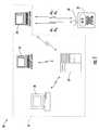
- FIG. 1is schematic block diagram of a wireless communications system in accordance with the present invention including a wireless local area network (WLAN) and wireless device detector for locating WLAN devices thereof.
- WLANwireless local area network
- FIG. 2is a schematic block diagram generally illustrating the components of the wireless device detector of FIG. 1 .
- FIG. 3is a graph illustrating the signal propagation delay and device latency components used by the controller of FIG. 2 to generate observed latency profiles.
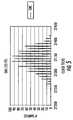
- FIGS. 4-6are histograms illustrating stored latency profiles used to determine propagation delay and range estimation by the wireless device detector of FIG. 2 .
- FIGS. 7 and 8are schematic block diagrams illustrating alternate embodiments of the wireless communications system of FIG. 1 including a mobile ad-hoc network (MANET) and a cellular network, respectively.
- MANETmobile ad-hoc network
- FIG. 9is a flow diagram illustrating a wireless device range detection method in accordance with the present invention.
- portions of the present inventionmay be embodied as a method, data processing system, or computer program product. Accordingly, these portions of the present invention may take the form of an entirely hardware embodiment, an entirely software embodiment, or an embodiment combining software and hardware aspects. Furthermore, portions of the present invention may be a computer program product on a computer-usable storage medium having computer readable program code on the medium. Any suitable computer readable medium may be utilized including, but not limited to, static and dynamic storage devices, hard disks, optical storage devices, and magnetic storage devices.
- These computer program instructionsmay also be stored in a computer-readable memory that can direct a computer or other programmable data processing apparatus to function in a particular manner, such that the instructions stored in the computer-readable memory result in an article of manufacture including instructions which implement the function specified in the flowchart block or blocks.
- the computer program instructionsmay also be loaded onto a computer or other programmable data processing apparatus to cause a series of operational steps to be performed on the computer or other programmable apparatus to produce a computer or other programmable apparatus implemented process such that the instructions which execute on the computer or other programmable apparatus provide steps for implementing the functions specified in the flowchart block or blocks.
- the present inventionmay make use of the wireless device locator and methods, as described in copending application Ser. No. 10/767,794, filed Jan. 29, 2004 by the same assignee of record and incorporated by reference herein in its entirety.
- a wireless communications system 30illustratively includes a wireless local area network (WLAN) 31 and a wireless device detector 32 .
- the WLAN 31illustratively includes an access point 33 (e.g., a server) and a plurality of WLAN devices or terminals which communicate therewith wirelessly, such as the laptop computers 34 , 35 , and the desktop computer 36 .
- Various WLAN protocolsmay be used in accordance with the present invention for such wireless communications (e.g., IEEE 802.11, Bluetooth, etc.), as will be appreciated by those of skill in the art.
- additional access points and/or other numbers of wireless communications devicesmay be used, even though only a few number thereof are shown for clarity of illustration.
- numerous other types of WLAN enabled wireless communications devicese.g., personal data assistants, etc. may also be used, as will be further appreciated by those skilled in the art.
- Each wireless communications device 34 - 36 in the WLAN 31has a device type associated therewith from among a plurality of different device types. More particularly, the device type may signify the particular manufacturer and/or model of a given WLAN card or chip set used therein. In some embodiments, it may also signify the standard the device complies with (e.g., IEEE 802.11).
- the device typeis important in that different device types will have known device latencies patterns associated therewith. For example, different WLAN cards or chip sets will have a certain latency associated with the time they take to process a received signal and generate an acknowledgement reply thereto. These delay times may be fairly consistent across different models from a same manufacturer. Additionally, WLAN protocols such as IEEE 802.11 have a specified Short InterFrame Spacing (SIFS) associated therewith, e.g. 10 ⁇ s as will be appreciated by those skilled in the art. More specifically, IEEE 802.11 protocol requires an Acknowledgement (Ack signal) to be issued by the MAC after a SIFS of 10 ⁇ s. In practice, such delay may vary by as much as 0.5 ⁇ s.
- SIFSShort InterFrame Spacing
- the latency of a given WLAN cardis chip set dependent and takes on discrete values, likely related to the MAC processor (often which is from the ARM family) and/or hardware implementation.
- a given WLAN cardwill have an Acknowledgement response time that varies over range of values. If a histogram of response time for numerous Acknowledgements is created for a given type of WLAN card, it will show a characteristic shape, or signature. This histogram, or latency profile, will be observed whenever the WLAN card is actively solicited with data packets that cause an Acknowledgement.
- the shape of the histogramis invariant to the distance between the wireless device detector and the target WLAN card, the amount that it is shifted in time (as compared to a known reference histogram) is proportional to the round trip propagation delay between the wireless device detector and the target WLAN card.
- the wireless device detector 32illustratively includes an antenna 39 and a transceiver 41 connected thereto, as well as a controller 42 connected to the transceiver. These components may conveniently be carried by a portable housing 43 in some embodiments, although they could be implemented in a more stationary embodiment, if desired.
- the antenna 39is a directional antenna, although omni-directional antennas may also be used, as will be appreciated by those skilled in the art. It will also be appreciated that various antenna/transceiver combinations may be used.
- the controller 42cooperates with the transceiver 41 for transmitting a plurality of device finding signals to a target wireless communications device to be located from among the plurality of wireless communications devices.
- the laptop 34is the target device.
- each WLAN device 34 - 36 in the network 31will have a unique identifier (UID) associated therewith which is used in signals transmitted between the respective devices and the access point 33 .
- the UIDdistinguishes the devices 34 - 36 from one another so that each device only acts upon or responds to signals intended for it, and so the access point 33 knows which device it is receiving signals from.
- the wireless device detector 32may or may not know the UID of the target device 34 before hand.
- the wireless device detector 32could download the UID from the access point 33 (either wirelessly or over a wired network connection, for example). This may be the case when trying to locate a node in a LAN where the node is already registered with the network.
- the wireless device detector 32may passively listen to the target device 34 for unsolicited signals being transmitted therefrom. This feature may be advantageous for law enforcement applications, or for locating an interfering node that is not registered with a particular network but causes interference therewith, for example.
- unsolicited signalsit is meant that these signals are not solicited by the wireless device locator 32 itself, although such signals may have been solicited from another source (e.g., the access point 33 ).
- the controller 42cooperates with the transceiver 41 to receive one or more of the unsolicited signals, and the controller determines the UID for the target device 34 therefrom.
- the method by which the controller 42 determines the UID from the unsolicited signalwill depend upon the given implementation, and whether or to what degree such signals are encrypted.
- the controller 42may also determine the device type of the target wireless communications device 34 based upon the UID thereof.
- the UIDsmay include media access control (MAC) addresses of respective wireless communications devices.
- the MAC addressesmay be specific to a particular type of device manufacturer, or indicate a particular operational protocol with which the device is operating, as will be appreciated by those skilled in the art. Accordingly, the controller may determine the device type of the target wireless communications device 34 based upon the MAC address thereof in some applications.
- the controllerinserts the UID therefor in each of the device finding signals.
- the location finding signalmay include the UID of the target device 34 in the header of valid packet that has no payload. This will force the target device 34 to generate a reply signal acknowledging receipt of the location finding signal (i.e., an ACK signal).
- a reply signalacknowledging receipt of the location finding signal (i.e., an ACK signal).
- various other location finding signalscould be used to cause the target terminal 34 to generate an ACK signal, as will be appreciated by those skilled in the art.
- the controller 42cooperates with the transceiver 41 for receiving the reply signals from the target device 34 via the antenna 39 .
- the device finding signals and reply signalsmay be radio frequency (RF), microwave, optical, or other suitable types of signals, as will be appreciated by those skilled in the art.
- the controller 42generates an observed latency profile, as described in detail below, for the target device 34 based upon the device finding signals and reply signals.
- the controller 42determines the propagation delay associated with the target device 34 based upon the observed latency profile and a known latency profile for such device type.
- the controller 42uses this propagation delay to estimate a range to the target device 34 .
- the propagation delayis preferably determined based upon a comparison (e.g. the lag of the maximum peak of the cross-correlation of the known latency profile and the observed latency histogram) of latency histograms, observed and known, of delays with respect to the target device 34 .
- the total round trip timewill include several components.
- the first componentis the time associated with transmitting a device finding signal 45 , which is illustrated with an arrow. That is, this is the time from the beginning of the device finding signal transmission (time t 0 ) to end thereof (time t 1 ).
- Two time axesare shown in FIG. 3 .
- the top or upper axisrepresents events that occur at the target device 34
- the bottom or lower axisrepresents events that occur at the wireless device locator 32 .
- the second component of the round trip timeis the propagation delay or time t PD1 it takes for the device finding signal 45 to travel from the wireless device detector 32 to the target device 34 (i.e., from time t 1 to t 2 ).
- the third component of the round trip timeis the device latency t DL of the target device 34 (i.e., from time t 2 to t 3 ). This is the time it takes the target device 34 to receive, process, and transmit a reply signal 46 or ACK signal, responsive to the device finding signal 45 .
- the final components of the round trip timeare propagation delay t PD2 of the reply signal 46 (i.e., from time t 3 to t 4 ), and the reception time thereof by the wireless device detector 32 (i.e., from time t 4 to t 5 ).
- the controller 42will know the times associated with the transmission of the device finding signal 45 (i.e., from time t 0 to t 1 ), as well as the time associated with the reception of the reply signal 46 (i.e., from time t 4 to t 5 ) for each round trip, since these can be readily measured by the controller.
- the quantities that the controller 42 will not knoware the propagation delays t PD1 , t PD2 and the actual device latency t DL .
- the controller 42will have access to the known device latency (e.g., a latency histogram) for the given device type of the target device 34 , which provides a profile of the actual device latency t DL that has been determined at a known reference distance.
- the known device latencycould be a measured value based upon collected data, it could be provided by manufacturers, or it could be based upon a value set in a communications standard, as discussed above, for example.
- the actual device latencywill likely vary somewhat from one transmission to the next for any wireless communications device, potentially by as little as a few nanoseconds to a few microseconds, depending upon device configurations, processing loads, etc.
- device latenciestend to vary from one transmission to the next. Since the location finding signals and reply signals are traveling at the speed of light, such variances can make a significant difference in the estimated distances. More particularly, light travels approximately 1000 ft. in one microsecond. Thus, if the device latency varies by one microsecond from one transmission to the next, the estimated distance to the target device 34 would similarly vary by 1000 ft. or so, which likely will be an unacceptable accuracy for many applications.
- the controller 42advantageously generates an observed latency profile or histogram which is a compilation of data including a plurality of observed device latencies that are compared with a known latency profile or histogram with respect to known device latencies to estimate the range to the target device 34 .
- the propagation delayis not solely based upon a single measured propagation delay, but rather upon a plurality thereof. More particularly, by estimating the range based upon a histogram of a plurality of propagation delays, the wireless device detector 32 mitigates the effects of the variations in the actual device latency time. This provides a significantly more accurate approximation of the device latency time and, thus, a more accurate range estimation.
- the controller 42may estimate the range based upon a comparison of the lag of the maximum peak of the cross-correlation of the observed latency histogram and the known latency histogram.
- FIGS. 4-6a test was conducted in accordance with the present invention in which approximately 1500 location finding signals were transmitted to various stationary wireless IEEE 802.11 devices.
- the time it took to receive the reply signalwas measured by ticks of an internal clock of the controller 42 , where each tick represents 7.567 ns. From FIG. 4 it may be seen that the reply signals from the target “Cisco” device were returned within between about 27,300 and 27,550 clock ticks, where the transmission of the respective location signals each began at 0 clock ticks.
- FIGS. 5 and 6represent the measurements of reply signals from target devices such as an “SMC” device and “ZoomAir” device, respectively. These histograms may be stored in a database in the controller 42 to be used in the comparison with the observed profiles or histograms, as discussed above.
- a mobile ad-hoc network (MANET) system 90illustratively includes a wireless device locator 92 including an antenna 99 , such as those described above, and a MANET 91 . More particularly, the MANET includes MANET nodes or devices 93 - 96 , of which the node 94 is the target node in the illustrated example.
- the wireless device detector 92performs range estimation in the same manner described above, except that it will operate in accordance with the appropriate MANET protocol used within the system 90 , as will be appreciated by those skilled in the art.
- FIG. 8Another embodiment is illustrated in FIG. 8 , in which a wireless device detector 102 having an antenna 109 is used within a cellular communications system 100 for locating cellular devices (e.g., cellular telephones) 104 - 106 in cellular network 101 .
- the cellular devices 104 - 106place and receive calls via a cellar tower 103 , as will be appreciated by those skilled in the art.
- the target deviceis the cell phone 104 .
- the wireless device detector 102will communicate using the appropriate operating protocol being used in the cellular network 101 (e.g., code-division multiple access (CDMA), GSM, etc.), as will be appreciated by those skilled in the art.
- CDMAcode-division multiple access
- a method aspect of the inventionis for detecting the range of a target wireless communications 34 device from among a plurality of wireless communications devices 34 - 36 .
- device finding signalsare transmitted to the target wireless communications device, at Block 112 , and respective reply signals for each of the device finding signals are received therefrom, at Block 114 .
- an observed latency profileis generated at Block 116 . If the device type (and, thus, the known latency profile) are known, at Block 118 , then the propagation delay associated with the transmission of each device finding signal and the respective reply signal therefor is determined based upon the known latency profile of the target wireless communications device 34 , at Block 120 .
- a range to the target wireless communications device 34is estimated based upon the determined propagation delay (Block 122 ), as previously discussed above, thus concluding the illustrated method (Block 124 ).
- the controller 42may determine the device type from the reply signal, as discussed above, or by comparing the observed profile or histogram with known profiles stored in a database (Block 119 ) or other suitable methods which will be appreciated by those skilled in the art. It should be noted that while this step is shown as occurring after the receipt of the reply signals in the illustrated example, the device type determination may be performed prior thereto, such as while determining the UID, for example.
Landscapes
- Engineering & Computer Science (AREA)
- Radar, Positioning & Navigation (AREA)
- Remote Sensing (AREA)
- Computer Networks & Wireless Communication (AREA)
- Signal Processing (AREA)
- Physics & Mathematics (AREA)
- General Physics & Mathematics (AREA)
- Mobile Radio Communication Systems (AREA)
Abstract
Description
Claims (24)
Priority Applications (1)
| Application Number | Priority Date | Filing Date | Title |
|---|---|---|---|
| US11/058,931US7778651B2 (en) | 2005-02-16 | 2005-02-16 | Wireless network range estimation and associated methods |
Applications Claiming Priority (1)
| Application Number | Priority Date | Filing Date | Title |
|---|---|---|---|
| US11/058,931US7778651B2 (en) | 2005-02-16 | 2005-02-16 | Wireless network range estimation and associated methods |
Publications (2)
| Publication Number | Publication Date |
|---|---|
| US20060183488A1 US20060183488A1 (en) | 2006-08-17 |
| US7778651B2true US7778651B2 (en) | 2010-08-17 |
Family
ID=36816292
Family Applications (1)
| Application Number | Title | Priority Date | Filing Date |
|---|---|---|---|
| US11/058,931Active2026-09-17US7778651B2 (en) | 2005-02-16 | 2005-02-16 | Wireless network range estimation and associated methods |
Country Status (1)
| Country | Link |
|---|---|
| US (1) | US7778651B2 (en) |
Cited By (21)
| Publication number | Priority date | Publication date | Assignee | Title |
|---|---|---|---|---|
| US8195118B2 (en) | 2008-07-15 | 2012-06-05 | Linear Signal, Inc. | Apparatus, system, and method for integrated phase shifting and amplitude control of phased array signals |
| US8872719B2 (en) | 2009-11-09 | 2014-10-28 | Linear Signal, Inc. | Apparatus, system, and method for integrated modular phased array tile configuration |
| US9025416B2 (en) | 2011-12-22 | 2015-05-05 | Pelco, Inc. | Sonar system for automatically detecting location of devices |
| US9584252B1 (en) | 2015-09-25 | 2017-02-28 | Harris Corporation | Managed access system with mobile wireless device geolocation capability |
| US9622159B2 (en) | 2015-09-01 | 2017-04-11 | Ford Global Technologies, Llc | Plug-and-play interactive vehicle interior component architecture |
| US9681360B1 (en) | 2016-05-13 | 2017-06-13 | Harris Corporation | Managed access system that provides selective communications and registration of mobile wireless devices |
| US9736706B2 (en) | 2015-09-25 | 2017-08-15 | Harris Corporation | Managed access system with monitoring device to determine system operability |
| US9744852B2 (en) | 2015-09-10 | 2017-08-29 | Ford Global Technologies, Llc | Integration of add-on interior modules into driver user interface |
| US9747740B2 (en) | 2015-03-02 | 2017-08-29 | Ford Global Technologies, Llc | Simultaneous button press secure keypad code entry |
| US9763095B2 (en) | 2015-09-25 | 2017-09-12 | Harris Corporation | Managed access system that determines authorized and unauthorized mobile wireless devices |
| US9769666B2 (en) | 2015-09-25 | 2017-09-19 | Harris Corporation | Managed access system with monitoring device to determine and change radio equipment |
| US9820150B2 (en) | 2015-09-25 | 2017-11-14 | Harris Corporation | Managed access system having filtered communications using network interface device |
| US9860710B2 (en) | 2015-09-08 | 2018-01-02 | Ford Global Technologies, Llc | Symmetrical reference personal device location tracking |
| US9914415B2 (en) | 2016-04-25 | 2018-03-13 | Ford Global Technologies, Llc | Connectionless communication with interior vehicle components |
| US9914418B2 (en) | 2015-09-01 | 2018-03-13 | Ford Global Technologies, Llc | In-vehicle control location |
| US9967717B2 (en) | 2015-09-01 | 2018-05-08 | Ford Global Technologies, Llc | Efficient tracking of personal device locations |
| US10046637B2 (en) | 2015-12-11 | 2018-08-14 | Ford Global Technologies, Llc | In-vehicle component control user interface |
| US10082877B2 (en) | 2016-03-15 | 2018-09-25 | Ford Global Technologies, Llc | Orientation-independent air gesture detection service for in-vehicle environments |
| US10284559B2 (en) | 2016-05-13 | 2019-05-07 | Harris Corporation | Managed access system with security assessment equipment |
| US10405184B2 (en) | 2017-01-31 | 2019-09-03 | Harris Corporation | Mobile wireless device managed access system providing enhanced authentication features and related methods |
| US11472293B2 (en) | 2015-03-02 | 2022-10-18 | Ford Global Technologies, Llc | In-vehicle component user interface |
Families Citing this family (17)
| Publication number | Priority date | Publication date | Assignee | Title |
|---|---|---|---|---|
| US7110779B2 (en)* | 2004-01-29 | 2006-09-19 | Harris Corporation | Wireless communications system including a wireless device locator and related methods |
| IL169855A (en)* | 2005-07-25 | 2014-05-28 | Elta Systems Ltd | System and method for enabling determination of a position of a receiver |
| IL169854A (en)* | 2005-07-25 | 2013-11-28 | Elta Systems Ltd | System and method for positiong a transponder |
| US7453391B1 (en)* | 2005-11-03 | 2008-11-18 | L-3 Communications, Corp. | System and method for asynchronous transmission of communication data to a periodically blanked radar receiver |
| DE102007031129A1 (en) | 2007-06-29 | 2009-01-02 | IHP GmbH - Innovations for High Performance Microelectronics/Institut für innovative Mikroelektronik | Mobile transceiver for use in e.g. wireless local area network, has distance determining unit determining distance between transceiver and another transceiver based on signal propagation delay between reception and transmission values |
| US8130680B1 (en) | 2008-01-24 | 2012-03-06 | L-3 Communications, Corp. | Method for timing a pulsed communication system |
| US7978610B1 (en) | 2008-01-24 | 2011-07-12 | L-3 Communications Corp. | Method for asynchronous transmission of communication data between periodically blanked terminals |
| US9876711B2 (en) | 2013-11-05 | 2018-01-23 | Cisco Technology, Inc. | Source address translation in overlay networks |
| US10116493B2 (en) | 2014-11-21 | 2018-10-30 | Cisco Technology, Inc. | Recovering from virtual port channel peer failure |
| US10142163B2 (en) | 2016-03-07 | 2018-11-27 | Cisco Technology, Inc | BFD over VxLAN on vPC uplinks |
| US10333828B2 (en) | 2016-05-31 | 2019-06-25 | Cisco Technology, Inc. | Bidirectional multicasting over virtual port channel |
| US11509501B2 (en) | 2016-07-20 | 2022-11-22 | Cisco Technology, Inc. | Automatic port verification and policy application for rogue devices |
| CN109565352A (en)* | 2016-08-12 | 2019-04-02 | 诺基亚通信公司 | Link Delay and System Behavior |
| US10193750B2 (en) | 2016-09-07 | 2019-01-29 | Cisco Technology, Inc. | Managing virtual port channel switch peers from software-defined network controller |
| US10547509B2 (en) | 2017-06-19 | 2020-01-28 | Cisco Technology, Inc. | Validation of a virtual port channel (VPC) endpoint in the network fabric |
| US11276648B2 (en)* | 2018-07-31 | 2022-03-15 | Nvidia Corporation | Protecting chips from electromagnetic pulse attacks using an antenna |
| US12395568B2 (en)* | 2022-08-15 | 2025-08-19 | Capital One Services, Llc | Systems and methods to determine the loss of ability to notify customer through mobile app and prompt re-download |
Citations (14)
| Publication number | Priority date | Publication date | Assignee | Title |
|---|---|---|---|---|
| US4042926A (en)* | 1975-03-27 | 1977-08-16 | The United States Of America As Represented By The Administrator Of The National Aeronautics And Space Administration | Automatic transponder |
| US5526357A (en) | 1991-08-16 | 1996-06-11 | Pinpoint Communications, Inc. | Communication system and method for determining the location of a transponder unit |
| US5550549A (en) | 1995-02-28 | 1996-08-27 | Harris Corporation | Transponder system and method |
| US5687196A (en) | 1994-09-30 | 1997-11-11 | Harris Corporation | Range and bearing tracking system with multipath rejection |
| US5706010A (en) | 1996-05-16 | 1998-01-06 | E-Systems, Inc. | Method and apparatus for determining location of an unknown signal transmitter |
| US6292665B1 (en) | 1998-10-08 | 2001-09-18 | Harris Corporation | Geolocation of cellular phone using supervisory audio tone transmitted from single base station |
| US20020080759A1 (en) | 2000-12-20 | 2002-06-27 | Wherenet Corp | Wireless local area network system with mobile access point station determination |
| US20020118655A1 (en) | 2000-12-01 | 2002-08-29 | Wherenet Corp | Wireless local area network with geo-location capability |
| US20030025602A1 (en) | 2001-07-31 | 2003-02-06 | Medtronic Physio-Control Manufacturing Corp | Method and system for locating a portable medical device |
| US20030034887A1 (en) | 2001-03-12 | 2003-02-20 | Crabtree Timothy L. | Article locator system |
| US20030043073A1 (en) | 2001-09-05 | 2003-03-06 | Gray Matthew K. | Position detection and location tracking in a wireless network |
| US6587514B1 (en)* | 1999-07-13 | 2003-07-01 | Pmc-Sierra, Inc. | Digital predistortion methods for wideband amplifiers |
| US7046987B2 (en)* | 2002-10-08 | 2006-05-16 | Northrop Grumman Corporation | Finding cell phones in rubble and related situations |
| US7110779B2 (en)* | 2004-01-29 | 2006-09-19 | Harris Corporation | Wireless communications system including a wireless device locator and related methods |
- 2005
- 2005-02-16USUS11/058,931patent/US7778651B2/enactiveActive
Patent Citations (15)
| Publication number | Priority date | Publication date | Assignee | Title |
|---|---|---|---|---|
| US4042926A (en)* | 1975-03-27 | 1977-08-16 | The United States Of America As Represented By The Administrator Of The National Aeronautics And Space Administration | Automatic transponder |
| US5526357A (en) | 1991-08-16 | 1996-06-11 | Pinpoint Communications, Inc. | Communication system and method for determining the location of a transponder unit |
| US5687196A (en) | 1994-09-30 | 1997-11-11 | Harris Corporation | Range and bearing tracking system with multipath rejection |
| US5550549A (en) | 1995-02-28 | 1996-08-27 | Harris Corporation | Transponder system and method |
| US5706010A (en) | 1996-05-16 | 1998-01-06 | E-Systems, Inc. | Method and apparatus for determining location of an unknown signal transmitter |
| US6292665B1 (en) | 1998-10-08 | 2001-09-18 | Harris Corporation | Geolocation of cellular phone using supervisory audio tone transmitted from single base station |
| US6587514B1 (en)* | 1999-07-13 | 2003-07-01 | Pmc-Sierra, Inc. | Digital predistortion methods for wideband amplifiers |
| US20020118655A1 (en) | 2000-12-01 | 2002-08-29 | Wherenet Corp | Wireless local area network with geo-location capability |
| US20020080759A1 (en) | 2000-12-20 | 2002-06-27 | Wherenet Corp | Wireless local area network system with mobile access point station determination |
| US20030034887A1 (en) | 2001-03-12 | 2003-02-20 | Crabtree Timothy L. | Article locator system |
| US20030025602A1 (en) | 2001-07-31 | 2003-02-06 | Medtronic Physio-Control Manufacturing Corp | Method and system for locating a portable medical device |
| US20030043073A1 (en) | 2001-09-05 | 2003-03-06 | Gray Matthew K. | Position detection and location tracking in a wireless network |
| US7046987B2 (en)* | 2002-10-08 | 2006-05-16 | Northrop Grumman Corporation | Finding cell phones in rubble and related situations |
| US7110779B2 (en)* | 2004-01-29 | 2006-09-19 | Harris Corporation | Wireless communications system including a wireless device locator and related methods |
| US7321777B2 (en)* | 2004-01-29 | 2008-01-22 | Harris Corporation | Wireless communications system including a wireless device locator and related methods |
Cited By (21)
| Publication number | Priority date | Publication date | Assignee | Title |
|---|---|---|---|---|
| US8195118B2 (en) | 2008-07-15 | 2012-06-05 | Linear Signal, Inc. | Apparatus, system, and method for integrated phase shifting and amplitude control of phased array signals |
| US8872719B2 (en) | 2009-11-09 | 2014-10-28 | Linear Signal, Inc. | Apparatus, system, and method for integrated modular phased array tile configuration |
| US9025416B2 (en) | 2011-12-22 | 2015-05-05 | Pelco, Inc. | Sonar system for automatically detecting location of devices |
| US11472293B2 (en) | 2015-03-02 | 2022-10-18 | Ford Global Technologies, Llc | In-vehicle component user interface |
| US9747740B2 (en) | 2015-03-02 | 2017-08-29 | Ford Global Technologies, Llc | Simultaneous button press secure keypad code entry |
| US9622159B2 (en) | 2015-09-01 | 2017-04-11 | Ford Global Technologies, Llc | Plug-and-play interactive vehicle interior component architecture |
| US9967717B2 (en) | 2015-09-01 | 2018-05-08 | Ford Global Technologies, Llc | Efficient tracking of personal device locations |
| US9914418B2 (en) | 2015-09-01 | 2018-03-13 | Ford Global Technologies, Llc | In-vehicle control location |
| US9860710B2 (en) | 2015-09-08 | 2018-01-02 | Ford Global Technologies, Llc | Symmetrical reference personal device location tracking |
| US9744852B2 (en) | 2015-09-10 | 2017-08-29 | Ford Global Technologies, Llc | Integration of add-on interior modules into driver user interface |
| US9769666B2 (en) | 2015-09-25 | 2017-09-19 | Harris Corporation | Managed access system with monitoring device to determine and change radio equipment |
| US9820150B2 (en) | 2015-09-25 | 2017-11-14 | Harris Corporation | Managed access system having filtered communications using network interface device |
| US9763095B2 (en) | 2015-09-25 | 2017-09-12 | Harris Corporation | Managed access system that determines authorized and unauthorized mobile wireless devices |
| US9736706B2 (en) | 2015-09-25 | 2017-08-15 | Harris Corporation | Managed access system with monitoring device to determine system operability |
| US9584252B1 (en) | 2015-09-25 | 2017-02-28 | Harris Corporation | Managed access system with mobile wireless device geolocation capability |
| US10046637B2 (en) | 2015-12-11 | 2018-08-14 | Ford Global Technologies, Llc | In-vehicle component control user interface |
| US10082877B2 (en) | 2016-03-15 | 2018-09-25 | Ford Global Technologies, Llc | Orientation-independent air gesture detection service for in-vehicle environments |
| US9914415B2 (en) | 2016-04-25 | 2018-03-13 | Ford Global Technologies, Llc | Connectionless communication with interior vehicle components |
| US9681360B1 (en) | 2016-05-13 | 2017-06-13 | Harris Corporation | Managed access system that provides selective communications and registration of mobile wireless devices |
| US10284559B2 (en) | 2016-05-13 | 2019-05-07 | Harris Corporation | Managed access system with security assessment equipment |
| US10405184B2 (en) | 2017-01-31 | 2019-09-03 | Harris Corporation | Mobile wireless device managed access system providing enhanced authentication features and related methods |
Also Published As
| Publication number | Publication date |
|---|---|
| US20060183488A1 (en) | 2006-08-17 |
Similar Documents
| Publication | Publication Date | Title |
|---|---|---|
| US7778651B2 (en) | Wireless network range estimation and associated methods | |
| US7110779B2 (en) | Wireless communications system including a wireless device locator and related methods | |
| US7006838B2 (en) | System and method for locating sources of unknown wireless radio signals | |
| CN104204846B (en) | For the method and apparatus of wireless short-range connection setup | |
| US6956527B2 (en) | Wireless network access point configuration | |
| US20050003828A1 (en) | System and method for locating wireless devices in an unsynchronized wireless environment | |
| US9291701B2 (en) | Device, system and method of estimating a relative location of a mobile device | |
| US8265011B2 (en) | High resolution wireless indoor positioning system for legacy standards-based narrowband mobile radios | |
| US10386451B2 (en) | Method for an enhanced time of arrival positioning system | |
| US20160282448A1 (en) | Localization using time-of-flight | |
| US10985787B1 (en) | System and method for generating phase-coherent signaling when ranging between wireless communications nodes | |
| US20230239831A1 (en) | Timing-based positioning techniques | |
| CN108337681B (en) | A detection method of wireless network Sybil attack based on channel state characteristics | |
| CN109196926B (en) | Method and apparatus for estimating a turnover calibration factor | |
| CN114720937A (en) | Determination method and related device for angle of arrival | |
| CN102792178B (en) | Method, apparatus, and computer program product for wireless signal storage with signal recognition detection triggering | |
| CN115428478B (en) | Method and device for fingerprint identification by adopting function-based matching mode | |
| TW200307141A (en) | System and method for locating wireless device in an unsynchronized wireless environment | |
| US10306585B2 (en) | Signal determining method and apparatus | |
| CN117768936A (en) | Channel measurement method and related device | |
| Zhu et al. | A location-determination application in wirelesshart | |
| US10085114B2 (en) | System and method for using multiple networks to estimate a location of a mobile communication terminal | |
| US20180267132A1 (en) | Method of Position and Motion Detection with Packet Communication | |
| US20240393419A1 (en) | System and method for geolocation identification and accuracy assessment of fixed wireless cpe endpoints | |
| WO2004043015A1 (en) | Proximity detector |
Legal Events
| Date | Code | Title | Description |
|---|---|---|---|
| AS | Assignment | Owner name:HARRIS CORPORATION, FLORIDA Free format text:ASSIGNMENT OF ASSIGNORS INTEREST;ASSIGNOR:BILLHARTZ, THOMAS JAY;REEL/FRAME:016305/0028 Effective date:20050210 | |
| STCF | Information on status: patent grant | Free format text:PATENTED CASE | |
| FPAY | Fee payment | Year of fee payment:4 | |
| MAFP | Maintenance fee payment | Free format text:PAYMENT OF MAINTENANCE FEE, 8TH YEAR, LARGE ENTITY (ORIGINAL EVENT CODE: M1552) Year of fee payment:8 | |
| AS | Assignment | Owner name:SPEIR TECHNOLOGIES LTD., IRELAND Free format text:ASSIGNMENT OF ASSIGNORS INTEREST;ASSIGNORS:L3HARRIS TECHNOLOGIES, INC.;EAGLE TECHNOLOGY, LLC;HARRIS GLOBAL COMMUNICATIONS, INC.;REEL/FRAME:058165/0685 Effective date:20210928 | |
| MAFP | Maintenance fee payment | Free format text:PAYMENT OF MAINTENANCE FEE, 12TH YEAR, LARGE ENTITY (ORIGINAL EVENT CODE: M1553); ENTITY STATUS OF PATENT OWNER: LARGE ENTITY Year of fee payment:12 | |
| AS | Assignment | Owner name:NERA INNOVATIONS LIMITED, IRELAND Free format text:ASSIGNMENT OF ASSIGNORS INTEREST;ASSIGNOR:SPEIR TECHNOLOGIES LIMITED;REEL/FRAME:066709/0250 Effective date:20240305 |