US7778262B2 - Radio frequency multiple protocol bridge - Google Patents
Radio frequency multiple protocol bridgeDownload PDFInfo
- Publication number
- US7778262B2 US7778262B2US11/634,909US63490906AUS7778262B2US 7778262 B2US7778262 B2US 7778262B2US 63490906 AUS63490906 AUS 63490906AUS 7778262 B2US7778262 B2US 7778262B2
- Authority
- US
- United States
- Prior art keywords
- communication
- communication protocol
- distinct
- decoded
- received
- Prior art date
- Legal status (The legal status is an assumption and is not a legal conclusion. Google has not performed a legal analysis and makes no representation as to the accuracy of the status listed.)
- Active, expires
Links
Images


Classifications
- H—ELECTRICITY
- H04—ELECTRIC COMMUNICATION TECHNIQUE
- H04W—WIRELESS COMMUNICATION NETWORKS
- H04W4/00—Services specially adapted for wireless communication networks; Facilities therefor
- H04W4/18—Information format or content conversion, e.g. adaptation by the network of the transmitted or received information for the purpose of wireless delivery to users or terminals
- H—ELECTRICITY
- H04—ELECTRIC COMMUNICATION TECHNIQUE
- H04L—TRANSMISSION OF DIGITAL INFORMATION, e.g. TELEGRAPHIC COMMUNICATION
- H04L69/00—Network arrangements, protocols or services independent of the application payload and not provided for in the other groups of this subclass
- H04L69/08—Protocols for interworking; Protocol conversion
- H—ELECTRICITY
- H04—ELECTRIC COMMUNICATION TECHNIQUE
- H04L—TRANSMISSION OF DIGITAL INFORMATION, e.g. TELEGRAPHIC COMMUNICATION
- H04L69/00—Network arrangements, protocols or services independent of the application payload and not provided for in the other groups of this subclass
- H04L69/18—Multiprotocol handlers, e.g. single devices capable of handling multiple protocols
- H—ELECTRICITY
- H04—ELECTRIC COMMUNICATION TECHNIQUE
- H04W—WIRELESS COMMUNICATION NETWORKS
- H04W80/00—Wireless network protocols or protocol adaptations to wireless operation
- H—ELECTRICITY
- H04—ELECTRIC COMMUNICATION TECHNIQUE
- H04W—WIRELESS COMMUNICATION NETWORKS
- H04W92/00—Interfaces specially adapted for wireless communication networks
- H04W92/02—Inter-networking arrangements
Definitions
- This inventionrelates to a method, apparatus, and system for interfacing between electronic devices and more particularly relates to a method, apparatus, and system for communication between electronic devices using different protocols and different modulation schemes.
- Manufacturer Amay make a motion detector and Manufacturer B may make automatic window blinds. Both may use some type of radio frequency protocol to enable remote access, but each operates at a different radio frequency, and they may each use different communication protocols to interact with a corresponding remote device. Neither remote device can work with the other product however.
- the invention disclosed hereinhas been developed in response to the present state of the art, and in particular, in response to the problems and needs in the art that have not yet been fully solved by currently available radio frequency interface devices. Accordingly, the present invention has been developed to provide an apparatus, system, and method for interfacing between electronic devices that overcome many or all of the above-discussed shortcomings present in the art.
- the illustrative apparatuswhich interfaces between electrical devices is provided with a plurality of modules configured to functionally execute one or more of the following steps: implementing the communication protocol(s) of one or more electronic devices, scanning for a first signal containing information transmitted in a learned communication protocol from one or more of the electrical devices, receiving and recognizing the first signal, decoding the first signal using the appropriate communication protocol to extract the desired information, translating the information extracted from the signal into a predetermined language, creating a second signal containing the translated information using a second communication protocol, sending the second signal to another electrical device, and receiving an acknowledgment that the second signal was received by the other electrical device.
- modules in the described illustrative embodimentsinclude a scanning module, a decoding module, a translation module, a send/receive module, and a handshake module.
- the apparatusin one illustrative embodiment, is configured to scan known frequencies on which multiple third-party and/or proprietary radio frequency devices operate. If the apparatus recognizes a signal in a known communication protocol on any of the frequencies, the apparatus may then demodulate and/or decode the signal to extract the desired information and then translate the information into a common predetermined communication language for sending to another electrical device.
- An illustrative system of the present inventionis also disclosed to interface between radio frequency devices.
- the systemmay be embodied in wireless network having programmable software, firmware, and hardware.
- the systemin one illustrative embodiment, includes a processor and a power supply.
- the systemmay also contain one or more radio frequency sensors or antenna.
- the systemmay also contain an AM/FM interface, a radio frequency sensor/antenna, and transceiver.
- a busmay operably connect the processor, sensors, transceiver, and third party radio frequency (AM/FM) interface.
- AM/FMthird party radio frequency
- the systemincludes a memory containing the modules that make up the system discussed above.
- the systemmay also include a controller that acts as a backend central control system.
- the controllermay communicate with the apparatus wirelessly.
- the controllermay communicate with the apparatus through any number of electronic connections, including low-voltage wiring, fiber optic, infra red, power line carrier and other media as can be devised by those skilled in the art.
- An illustrative method of the present inventionis also presented for interfacing between radio frequency devices.
- the method in the illustrative embodimentssubstantially includes the steps necessary to carry out the functions presented above with respect to the operation of the described apparatus and system.
- the methodincludes determining the frequency of one or more radio devices, scanning known frequencies for a signal using a known communication protocol and decoding the communication protocol.
- the methodmay also include the steps of converting the decoded information in the signal into a predetermined interface language and creating a communication packet containing the converted communication protocol for sending to controller.
- the methodincludes the step of receiving an acknowledgment that the communication packet was received by the radio frequency device controller.
- the method steps disclosed hereinmay also be embodied as operations carried out by the computer-readable code of a computer program product.
- Another illustrative aspect of the present inventionincludes minimizing the total scanning time on any particular frequency by an apparatus such that the possibility of a missed signal on another frequency is reduced.
- the apparatusmay only analyze a small fraction of a signal to determine if the signal is a valid signal using a known protocol. When a valid signal is detected, the apparatus will proceed to analyze the whole signal, otherwise the signal is discarded and the apparatus continues scanning.
- Another illustrative aspect of the present inventionincludes limiting the total scanning time for all of the frequencies scanned by an apparatus.
- each communication protocol for which an apparatus is designed to scanis weighted to determine the resources used by that communication protocol. If the available resources are overextended such that the apparatus would likely miss a signal while scanning, the apparatus may dynamically optimize its scanning procedure to reduce the likelihood of a missed signal while scanning, prohibit additional communication protocols, or require the elimination of one of the communication protocols.
- FIG. 1is a schematic block diagram illustrating one illustrative embodiment of a system for interfacing between radio frequency devices in accordance with the present invention
- FIG. 2is a schematic block diagram illustrating one illustrative embodiment of an apparatus for interfacing between a radio frequency devices in accordance with the present invention
- FIG. 3is a schematic block diagram illustrating another illustrative embodiment of an apparatus for interfacing between a radio frequency devices in accordance with the present invention
- FIG. 4is a schematic flow chart diagram illustrating one illustrative embodiment of a method in accordance with the present invention.
- FIG. 5is a schematic flow chart diagram illustrating another illustrative embodiment of a method in accordance with the present invention.
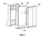
- FIG. 6is a prospective exploded view illustrating one embodiment of an illustrative radio frequency interface apparatus in accordance with the present invention.
- modulesmay be implemented as a hardware circuit comprising custom VLSI circuits or gate arrays, off-the-shelf semiconductors such as logic chips, transistors, or other discrete components.
- a modulemay also be implemented in programmable hardware devices such as field programmable gate arrays, programmable array logic, programmable logic devices or the like.
- Modulesmay also be implemented in software for execution by various types of processors.
- An identified module of executable codemay, for instance, comprise one or more physical or logical blocks of computer instructions that may, for instance, be organized as an object, procedure, or function. Nevertheless, the executables of an identified module need not be physically located together, but may comprise disparate instructions stored in different locations which, when joined logically together, comprise the module and achieve the stated purpose for the module.
- a module of executable codemay be a single instruction, or many instructions, and may even be distributed over several different code segments, among different programs, and across several memory devices.
- operational datamay be identified and illustrated herein within modules, and may be embodied in any suitable form and organized within any suitable type of data structure. The operational data may be collected as a single data set, or may be distributed over different locations including over different storage devices, and may exist, at least partially, merely as electronic signals on a system or network.
- Reference to computer program productmay take any form capable of generating a signal, causing a signal to be generated, or causing execution of a program of machine-readable instructions on a digital processing apparatus.
- a computer program productmay be embodied by a transmission line, a compact disk, digital-video disk, a magnetic tape, a Bernoulli drive, a magnetic disk, a punch card, flash memory, integrated circuits, or other digital processing apparatus or memory device which can be arrived at by those skilled in the art.
- FIG. 1depicts a system, generally designated at 100 , according to the present invention.
- the system 100may include one or more radio devices 102 A- 102 D and wired devices 102 E and 102 F.
- the devices 102 A- 102 Fmay be third party devices or proprietary devices that emit a radio frequency signal.
- the devices 102 A- 102 Fare off-the-shelf devices.
- radio device 102 Amay be any of a number of fobs, including, but not limited to an engine starter, a garage door opener, a keyless entry device, network access device, a home lighting access device, a home environment access device, and the like.
- radio device 102 Bmay be a motorized device capable of receiving a radio frequency signal and transmitting status signals.
- radio device 102 Bmay be automatic window blinds that can be raised or lowered through a radio-controlled motor.
- radio device 102 Bis a motorized blind manufactured by SOMFY®.
- Radio device 102 Cmay be a motion sensor or other home security device capable of emitting a radio signal.
- radio device 102 Dis a proprietary device specifically manufactured for use in the system.
- Device 102 Emay be a switch capable of transmitting a low voltage signal, including a signal indicating a momentary switch closure.
- Device 102 Fmay be a device capable of accepting a low voltage signal, such as a signal indicating a momentary switch closure.
- a low voltage signalsuch as a signal indicating a momentary switch closure.
- suitable devices for use with the present inventioninclude all types of radio controlled devices, including garage door openers, ceiling fans, motion sensors, garage door openers, remote controls, lighting controls and blind controls.
- the radio devices 102 A- 102 Dmay communicate with an interface 108 by means of radio waves 104 .
- the interface 108includes a radio frequency antenna 106 A to pick up the radio waves 104 .
- the interface 108may have a range from the devices 102 A- 102 D of up to about 50 feet.
- the radio devices 102 A- 102 Dcommunicate with the interface 108 through a wired connection.
- the interface 108can send and receive signals to and from the devices 102 A- 102 D via the antenna 106 A. It will be appreciated that each device 102 A- 102 D may use its own distinct communication protocol.
- the interface 108can recognize multiple communication protocols to thereby communicate with all of devices 102 A- 102 D.
- the devices 102 E and 102 Fmay communicate with interface 108 via a wired connection.
- the wired connectionis a low voltage wired connection.
- the interface 108may also include a processor 110 for executing control commands.
- the processormay be an Atmel MEGA Processor.
- the processor 110may be an ARM processor.
- the interface 108may also include a power supply 112 .
- the power supplymay be an AC to DC power supply.
- the power sourcemay also be an AC power source, such as from a power grid, or a battery.
- the interface 108may include a third party radio frequency interface, which in the illustrative embodiment is represented as a secondary radio interface 114 .
- the secondary radio interface 114can be programmed to communicate with any radio frequency device within predetermined frequency ranges.
- the frequency rangeis between about 100 MHZ and about 600 MHZ.
- the frequency rangeis between about 600 MHZ and about 1000 MHZ.
- the frequency rangeis between about 300 MHZ and 1000 MHZ.
- the secondary radio interface 114can be programmed to read and decode radio frequency devices in other frequencies ranges and many different communication protocols.
- the secondary radio interface 114may use half duplex bi-directional radio frequency communication.
- the interface 108includes a common language interface module, which in the illustrative embodiment is represented as a primary radio interface 116 .
- the primary radio interface 116may send and receive signals 107 through antenna 106 B.
- the primary radio interface 116may be a universal asynchronous radio transceiver of a kind known in the industry.
- the primary radio interface 116includes a transceiver which is configured to operate as part of the common language interface module.
- the primary radio interface 116is generally configured to handle a single protocol, both incoming and outgoing and in this manner operates as a common language interface module.
- the primary radio interface 116operates in the frequency range of about 902 MHZ to 928 MHZ.
- the interface 108may therefore include two separate co-located radio transceivers, namely the primary radio interface 116 and the secondary radio interface 114 .
- a memory 118may store executable code for operating the system 100 . It will be appreciated by those of skill in the art that the code may also be embodied as hardware or firmware.
- the memory 118may include one or more translation modules for bridging communication between the secondary radio interface 114 and the primary radio interface 116 . The translation modules are executed by processor 110 .
- the memory 118could include separate translation modules for communicating with each device 102 A- 102 D. This is due to the fact that each of the devices 102 A- 102 D may be manufactured by different manufacturers. Traditionally, each manufacturer uses its own proprietary communications protocol with its devices. For this reason, a separate translation module may be required for each device 102 A- 102 D.
- the secondary radio interface 114 and the primary radio interface 116may cause the execution of the translation modules to accomplish the functionality associated with each one. For example, an incoming signal from any of the devices 102 A- 102 D is received by secondary radio interface 114 . Once received, the interface 108 calls upon the appropriate translation module to recognize the protocol of the signal, decode the signal using the appropriate communication protocol to extract the desired information, and translate the information extracted from the signal into the common language. The primary radio interface 116 then transmits the information in the common language.
- a signalmay be received at the primary radio interface 116 .
- the interface 108may then call upon the appropriate translation module to translate information in the signal into the specified third party's communication protocol.
- the interface 108can then send the signal to the appropriate device 102 A- 102 D through the secondary radio interface 114 .
- the translation modulesmay format the information, such as control commands, into the appropriate communications protocol required by the intended recipient device. This may include the appropriate headers, preambles, commands, etc. required to communicate with the devices 102 A- 102 D. This may also include the correct encoding scheme, how to start or end a message, handshaking, and error correction schemes. This may further include the correct frequency and modulation schemes. Likewise, the translation modules are able to decode the message into the common interface language. In one embodiment, the translation modules are dynamically upgradeable such that new devices may be added to the system 100 at any time.
- the communication protocolIn order to create a translation module for a communication protocol, the communication protocol must be identified and analyzed. In the case of a third party manufacturer, it is preferable to secure the cooperation of the manufacturer to provide the information on its proprietary protocol.
- the third party protocolmay also utilize a proprietary communication language.
- the languagemay include commands and status information.
- the commandsmay include “up,” “down,” “open,” and “close.” These commands must be correlated to the generic commands of the common interface language which may include commands having the same meaning.
- the translation modulecan translate the “up” command in the common interface language to the “up” command of the third party protocol and vice versa.
- the interface 108is able to mimic a third party control device. That is, the controlled devices 102 A- 102 D do not know that the command originated from the interface 108 instead of its own remote control device.
- the interface 108includes a relay 122 , which is a low-voltage relay of a kind known in the art.
- the relaymay be a 1 amp 40 VDC relay.
- Interface 108also includes the appropriate circuitry to drive relay 122 .
- Interface 108may send a signal to device 102 F using the relay 122 .
- a detected signal 104 or 107could cause the relay 122 to be activated to emulate a contact switch closure to device 102 F.
- the interface 108may include a contact input 120 to detect a momentary switch closure. When a momentary switch closure is detected through contact input 120 , the interface 108 then translates this information into the common interface language and sends a message to a controller 126 .
- Device 102 Emay provide the contact input signal.
- the controller 126executes programming in response to that contact input 120 , which may include sending a signal back to the interface 108 instructing it to close the relay 122 as well as carrying out any number of pre-programmed instructions, such as sending a signal to any of devices 102 A- 102 D.
- the inclusion of the contact inputs 120allows the interface 108 to receive input from wired third-party devices, such as most passive infrared motion detectors, door contacts, stress sensors, light sensors, humidity and temperature sensors, smoke and carbon monoxide detectors, garage door openers and more.
- the inclusion of the relay 122allows the interface 108 to control devices as well as emulate devices that are responsive to switch closures.
- the interface 108may also include a display 128 to facilitate use of the system 100 by a user.
- the display 128is an LED display.
- the system 100also includes a controller, such as the controller 126 shown in FIG. 1 .
- Suitable controllersinclude the C-BOXTM Controller, C-BOX LE Controller, and INFUSIONTM Controller manufactured by Vantage Controls, Inc.
- Other suitable controllersinclude desktop computers, laptop computers, and other computing devices.
- the controller 126may form part of a commercial or a residential automation control systems.
- the controller 126may form part of a computer network. In that regard, the controller 126 may also be part of a network of any sort.
- the controller 126may be operably connected to a radio frequency enabler 124 to facilitate communication with the interface 108 .
- the radio-frequency enabler 124includes a radio frequency antenna 105 for sending and receiving signals 107 to and from the antenna 106 B of the interface 108 .
- a suitable radio frequency enablerincludes the RADIOLINK® Enabler manufactured by Vantage Controls, Inc.
- the range between the controller 126 and the interface 108may be up to about 150 feet.
- the radio frequency enabler 124is built into the controller 126 .
- the interface 108is wired to the controller 126 and uses an RS-232 protocol.
- the interface 108is wired to the controller 126 using low voltage communications bus.
- the interface 108acts as a radio frequency bridge.
- a networksuch as a home automation network or computer network, that may include the controller 126 .
- the interface 108forms a bridge between the network and third-party devices 102 A- 102 F.
- the third-party devices 102 A- 102 F side of the interface 108there will be an in and/or out communication protocol.
- one of the devices 102 A- 102 F in the system 100communicates with the controller 126 and receives commands from it to control a set of blinds 102 B that are controlled through a radio protocol.
- the interface 108would receive a command from the controller 126 , emulate the SOMFY® blind protocol and control the device 102 B.
- the interface 108could bridge to a motion sensor 102 C that sends out a radio signal when it detects motion.
- the interface 108would receive that signal, convert it to a message to the controller 126 , which would alert a user or carry-out some other preprogrammed operation.
- the system 100is capable of having multiple third-party protocols running simultaneously.
- one advantage of the present inventionis that a single interface 108 can communicate with multiple different manufacturers' products, as represented at 102 A- 102 F, instead of requiring multiple devices to communicate with the products 102 A- 102 F.
- the interface 102integrates and bridges the devices 102 A- 102 F and allows outside interface capability.
- the interface 108is configured to integrate this down to one common interface language and makes that available to an outside network.
- that outside networkis a network containing the controller 126 .
- the outside networkcould be a wired proprietary network.
- the outside networkcould be an RS-232 outside interface that could then be utilized by anything with that particular communication protocol capability.
- the connectionmay include without limitation, category 5 wire, Ethernet, and or use any other media format which can be selected by those skilled in the art. It will be appreciated that the interface 108 advantageously acts as a universal translator.
- some key fob devices 102 AWith some devices, for example some key fob devices 102 A, they are multi-frequency units and must be aligned with devices on their network. This requires significant power from these battery-operated devices. If they were powered up all the time, their battery would drain very quickly. Accordingly, some key fob devices 102 A go into a power saving or “hibernation” mode.
- the system 100 of the present inventionallows a user to hit a button on the key fob device 102 A which wakes up, transmits, goes back to sleep and it never has to wake up again if the user doesn't ever hit a button again.
- the battery-operated key fobtypically has a much simpler radio frequency protocol to save power.
- the systemalso allows a user to lower the window blinds 102 B because the motion sensor 102 C was tripped, even though they are made by different manufacturers using different protocols.
- the motion sensor 102 Cwhen it is tripped, it sends a signal to the interface 108 .
- the interfacedecodes and translates the signal into the common interface language.
- the interface 108then sends a signal 107 to the controller 126 indicating that the motion sensor 102 C has been tripped.
- programming on the controller 126which instructs the controller 126 to cause the blinds 102 B to lower if the motion sensor 102 C has been tripped.
- the controller 126would send the interface 108 a common interface packet using the common interface language.
- the interface 108would receive the signal and determine what action to take. For example, the command from the controller 126 may be to “Interface with the blinds 102 B and send the user's particular command to it to lower the blinds.”
- the interface 108knowing the particular communication protocol for the blind 102 B, would form a communication packet to go out over that communication protocol and then indicate to the internal logic that a command is ready to go.
- the interface 108finds a time slot it will transmit on the particular frequency used by the blinds 102 B and using the modulation protocol associated with the blinds 102 B and with appropriate timing with the third-party device 102 B, lower the blinds.
- two previously unrelated devicesare able to interact one with another.
- the apparatus 200is the interface 108 of FIG. 1 .
- the apparatus 200may include a processor 202 and a power supply 204 of the type discussed in connection with the system above.
- the apparatus 200may also include an secondary radio interface 206 , a primary radio interface 208 , and a memory 218 , as discusses above.
- the apparatus 200also include, antennas 210 , contact inputs 212 , at least one relay 214 , and a display 218 to facilitate communication with remote radio frequency devices and/or radio frequency control devices.
- the processor 202 , power supply 204 , secondary radio interface 206 , primary radio interface 208 , memory 218 , antennas 210 , contact inputs 212 , relay 214 , and display 218may be operably connected via communication bus 216 .
- FIG. 3illustrates one illustrative embodiment of an apparatus 300 according to the present invention.
- the apparatus 300includes a scanning module 302 .
- the scanning module 302may scan the known radio frequencies of third party or proprietary radio devices 102 (see FIG. 1 ).
- the scanning module 302detects a signal on a known frequency.
- the scanning module 302compares a preamble or a first portion of the signal to the known communications protocol for that frequency to determine if the signal is a valid signal. If the preamble or first portion is validated, then the scanning module 302 accepts and processes the signal. If the preamble or first portion is not validated, the signal is discarded and the scanning module 302 can scan the next frequency.
- the scanning module 302limits the time spent on any one frequency searching for a valid signal. If the scanning module 302 scans one frequency too long or it takes too long to recognize a valid signal, then a signal on another frequency may be lost.
- the apparatusmay also include a decoding module 304 configured to decode and/or demodulate a communication protocol utilized by a third-party or proprietary device recognized by the scanning module 302 on a particular frequency used by that third-party of proprietary device.
- a communication protocolmay include without limitation, a signal, communication, or other recognizable information on a particular frequency.
- the types of communication protocolsmay include without limitation, FM, AM, OOK, FSK, and the like.
- the apparatusalso includes a conversion module 306 configured to convert the decoded communication protocol into a predetermined communication language that can be interpreted by a controller type device or that can convert a predetermined communication language into a communication protocol.
- the decoding module 304in connection with the conversion module 306 , is capable of converting the commands and communications of multiple third party and proprietary devices into a single language or communication protocol for sending to a controller.
- the apparatus 300may include a send/receive module 308 configured to send and receive communication packets containing data in the common communication language to and from a controller, respectively.
- the send/receive module 308may also be configured to send and receive communication packets to devices in their own proprietary communication protocol.
- the apparatus 300also includes a handshake module 310 .
- the handshake module 310establishes a communication path or link between the apparatus 300 and a radio frequency controller such that communication packets can be sent and the receipt of the communication packets can be acknowledged.
- the apparatus 300also includes a weighting module 312 .
- the weighting module 312employs a weighting factor to determine the allowable combination of radio frequencies to be scanned by the scanning module 302 . For each scanned frequency, i.e., each communication protocol being scanned for, the weighting module 312 may determine the amount of time required to “lock” onto a signal using a particular protocol. If the time required to recognize a signal is excessive, a signal on another frequency may be missed. Ideally, the scanning module 302 never misses any signals. However, if the scanning module 302 spends too much time away from any one particular frequency while scanning for signals on other frequencies, then a signal on that particular frequency is likely to be missed.
- any particular communications protocolmay require that a signal using that protocol be repeated any number of times.
- the scanning module 302may spend more time away from that particular frequency on which the signal is being transmitted. This is because, if a signal is missed while scanning another frequency, the signal is still likely to be received by the apparatus 300 when it returns to the signal's frequency due to the fact that the signal is repeated. Thus, the more times a signal is repeated, the more time the scanning module 302 can spend scanning other frequencies.
- the speed, or transmission rate, of the signal being receivingis taken into consideration by the weighting module 312 . If the signal is slow, and each bit time is very long, it will take more time to lock onto a signal. Alternatively, if the signal is very fast, the lock time will be reduced, but the minimum allowed time away from that signal's frequency will also be greatly reduced hindering the allowed time on other channels.
- the weighting module 312may therefore take into account the time required to lock onto and validate a preamble or a first portion of a signal, whether the communication protocols call for repeating a signal, and the transmission rate of the signal being received in order to limit the number of scanned frequencies.
- the apparatus 300may be limited to scanning only one or two frequencies. If a communication protocol calls for repeating a signal multiple times, then it is more likely that the scanning module 312 will detect the signal even if the actual time scanning the frequency of the signal is relatively short. If the speed of the signal is slow, and each bit time is very long, it will take more time to validate a signal. Alternatively, if the signal's transmission rate is very fast, the lock time will be reduced, but the minimum time away from the frequency of the signal will be also be reduced hindering the allowed time on other frequencies.
- each communication protocolwill be weighted according to the factors discussed above to determine or limit the amount of frequencies scanned by the scanning module 302 .
- This weightwill determine the allowable combination of user protocols per apparatus 300 .
- this protocolcould be weighted at 100% meaning that only it would be allowed to operate on apparatus 300 .
- a protocol that calls for a very fast signal that is repeated ten (10) timescould be weighted at 10%.
- the apparatus 300could comfortably scan for this protocol as well as another, assuming that this other protocol does not impair the ability to detect the first protocol.
- FIGS. 1 , 2 , and 3disclose means for determining the frequency of one or more radio devices, means for scanning known frequencies for a communication protocol, means for decoding the communication protocol, means for converting the decoded communication protocol into a predetermined interface language, means for creating a communication packet containing the converted communication protocol means for sending the communication packet to a radio device controller, and means for receiving an acknowledgment that the communication packet was received by the radio device controller.
- FIG. 4illustrates a method 400 of interfacing between radio frequency devices according to the present invention.
- the method 400starts 402 by determining 404 the frequency of third party and/or proprietary devices on which the devices operate. Those frequencies are scanned 406 to determine whether or not any signals, communications, or other communication protocols are being transmitted. Signals, communications, and/or communication protocols are then decoded and/or demodulated 408 and converted 410 into a common interface language. In will be appreciated that the common interface language may be in and of itself a communication protocol.
- the method 400then creates a communication packet 412 containing the decoded signal from the remote third party and/or proprietary device and sends it to a controller 414 . The receipt of the communication packet is acknowledged 416 and the method ends 418 .
- FIG. 5illustrates one exemplary embodiment of a method 500 for interfacing between radio devices.
- the method 500starts 502 and scans the frequency on which a desired remote device operates. If a communication protocol is not detected 506 on that frequency, a next known frequency is scanned 514 . It will be appreciated that it is within the scope of the present invention that when the next frequency is unknown, it can be automatically determined.
- a next frequencyis scanned 518 .
- Previously known or currently determined frequenciesare scanned randomly or in order until a signal, communication, or other communication protocol is found.
- known frequenciesare scanned in order from a first known frequency until a last known frequency and then the scanning repeats in the same order.
- a communication protocolis found, it is decoded 508 and converted 510 into a predetermined communication language.
- the converted communication protocolis then packaged in a communication packet and sent to a controller or other device.
- the deviceis a controller that interacts with a user in order to operate one or more different radio frequency devices, even if those different devices operate at different radio frequencies or different modulations.
- the processmay then repeat or end 520 .
- FIG. 6illustrates one illustrative embodiment of an apparatus 600 for interfacing between radio devices according to the present invention.
- the apparatus 600may be embodied as a wall-mount structure.
- the apparatus 600includes a front cover 602 and a back cover 604 .
- a circuit board 606may include memory or circuitry for interfacing between third party and/or proprietary devices, and a controller that is operated by a user.
- the apparatus 600also includes a power supply 608 .
- a panel 610may help connect the front cover 602 , back cover 604 , circuit board 608 , and power supply 610 .
Landscapes
- Engineering & Computer Science (AREA)
- Computer Networks & Wireless Communication (AREA)
- Signal Processing (AREA)
- Computer Security & Cryptography (AREA)
- Communication Control (AREA)
Abstract
Description
This application claims the benefit of U.S. Provisional Application No. 60/715,115, filed Sep. 7, 2005, which is hereby incorporated by reference herein in its entirety, including but not limited to those portions that specifically appear hereinafter, the incorporation by reference being made with the following exception: In the event that any portion of the above-referenced provisional application is inconsistent with this application, this application supercedes said above-referenced provisional application.
Not Applicable.
1. Field of the Invention
This invention relates to a method, apparatus, and system for interfacing between electronic devices and more particularly relates to a method, apparatus, and system for communication between electronic devices using different protocols and different modulation schemes.
2. Background Art
Advances in technology have enabled manufacturers of many consumer products to automate their products and make customer use of the product more convenient. Many products today provide remote access of a product to a customer through radio waves. For example, people can open their garages without leaving their car and can determine whether security sensors in their house have been tripped. The problem, however, is that these devices often operate on different radio frequencies or use different communication protocols so that each product must have a unique corresponding device to interpret the radio frequency transmissions. As more and more products allow for remote access, the number of corresponding radio frequency devices increases. This creates clutter and makes operation of the devices cumbersome, which often negates the desired convenience to the customer.
For example, Manufacturer A may make a motion detector and Manufacturer B may make automatic window blinds. Both may use some type of radio frequency protocol to enable remote access, but each operates at a different radio frequency, and they may each use different communication protocols to interact with a corresponding remote device. Neither remote device can work with the other product however.
From the foregoing discussion, it will be appreciated that it would be an advancement in art to have a multiple protocol apparatus that is compact and cost-effective. It would be an additional advancement to have such an apparatus that could interface with devices having different radio frequencies that span large band gaps. It would be a further advancement to provide such an apparatus that could interface with devices having different types of modulation, be it amplitude modulation or frequency modulation. It would be a further advancement to have such an apparatus that is dynamically upgradeable such that new devices can be added. Such an apparatus is disclosed and claimed herein.
The features and advantages of the invention will be set forth in the description which follows, and in part will be apparent from the description, or may be learned by the practice of the invention without undue experimentation. The features and advantages of the invention may be realized and obtained by means of the instruments and combinations particularly pointed out in the appended claims.
The invention disclosed herein has been developed in response to the present state of the art, and in particular, in response to the problems and needs in the art that have not yet been fully solved by currently available radio frequency interface devices. Accordingly, the present invention has been developed to provide an apparatus, system, and method for interfacing between electronic devices that overcome many or all of the above-discussed shortcomings present in the art.
The illustrative apparatus which interfaces between electrical devices is provided with a plurality of modules configured to functionally execute one or more of the following steps: implementing the communication protocol(s) of one or more electronic devices, scanning for a first signal containing information transmitted in a learned communication protocol from one or more of the electrical devices, receiving and recognizing the first signal, decoding the first signal using the appropriate communication protocol to extract the desired information, translating the information extracted from the signal into a predetermined language, creating a second signal containing the translated information using a second communication protocol, sending the second signal to another electrical device, and receiving an acknowledgment that the second signal was received by the other electrical device.
These modules in the described illustrative embodiments include a scanning module, a decoding module, a translation module, a send/receive module, and a handshake module. The apparatus, in one illustrative embodiment, is configured to scan known frequencies on which multiple third-party and/or proprietary radio frequency devices operate. If the apparatus recognizes a signal in a known communication protocol on any of the frequencies, the apparatus may then demodulate and/or decode the signal to extract the desired information and then translate the information into a common predetermined communication language for sending to another electrical device.
An illustrative system of the present invention is also disclosed to interface between radio frequency devices. The system may be embodied in wireless network having programmable software, firmware, and hardware. In particular, the system, in one illustrative embodiment, includes a processor and a power supply. The system may also contain one or more radio frequency sensors or antenna. The system may also contain an AM/FM interface, a radio frequency sensor/antenna, and transceiver. A bus may operably connect the processor, sensors, transceiver, and third party radio frequency (AM/FM) interface.
In one illustrative embodiment, the system includes a memory containing the modules that make up the system discussed above. The system may also include a controller that acts as a backend central control system. In one illustrative embodiment, the controller may communicate with the apparatus wirelessly. In another illustrative embodiment, the controller may communicate with the apparatus through any number of electronic connections, including low-voltage wiring, fiber optic, infra red, power line carrier and other media as can be devised by those skilled in the art.
An illustrative method of the present invention is also presented for interfacing between radio frequency devices. The method in the illustrative embodiments substantially includes the steps necessary to carry out the functions presented above with respect to the operation of the described apparatus and system. In one illustrative embodiment, the method includes determining the frequency of one or more radio devices, scanning known frequencies for a signal using a known communication protocol and decoding the communication protocol. The method may also include the steps of converting the decoded information in the signal into a predetermined interface language and creating a communication packet containing the converted communication protocol for sending to controller. In another illustrative embodiment, the method includes the step of receiving an acknowledgment that the communication packet was received by the radio frequency device controller. The method steps disclosed herein may also be embodied as operations carried out by the computer-readable code of a computer program product.
Reference throughout this specification to features, advantages, or similar language does not imply that all of the features and advantages that may be realized with the present invention should be or are in any single embodiment of the invention. Rather, language referring to the features and advantages is understood to mean that a specific feature, advantage, or characteristic described in connection with an embodiment is included in at least one embodiment of the present invention. Thus, discussion of the features and advantages, and similar language, throughout this specification may, but do not necessarily, refer to the same illustrative embodiment.
Furthermore, the described features, advantages, and characteristics of the invention may be combined in any suitable manner in one or more embodiments. One skilled in the relevant art will recognize that the invention may be practiced without one or more of the specific features or advantages of a particular embodiment. In other instances, additional features and advantages may be recognized in certain embodiments that may not be present in all embodiments of the invention.
Another illustrative aspect of the present invention includes minimizing the total scanning time on any particular frequency by an apparatus such that the possibility of a missed signal on another frequency is reduced. In one illustrative embodiment, the apparatus may only analyze a small fraction of a signal to determine if the signal is a valid signal using a known protocol. When a valid signal is detected, the apparatus will proceed to analyze the whole signal, otherwise the signal is discarded and the apparatus continues scanning.
Another illustrative aspect of the present invention includes limiting the total scanning time for all of the frequencies scanned by an apparatus. In one embodiment, each communication protocol for which an apparatus is designed to scan is weighted to determine the resources used by that communication protocol. If the available resources are overextended such that the apparatus would likely miss a signal while scanning, the apparatus may dynamically optimize its scanning procedure to reduce the likelihood of a missed signal while scanning, prohibit additional communication protocols, or require the elimination of one of the communication protocols.
The features and advantages of the present invention will become more fully apparent from the following description and appended claims, or may be learned by the practice of the invention as set forth hereinafter.
In order that the advantages of the invention will be readily understood, a more particular description of the invention briefly described above will be rendered by reference to specific embodiments that are illustrated in the appended drawings. Understanding that these drawings depict only typical embodiments of the invention and are not therefore to be considered to be limiting of its scope, the invention will be described and explained with additional specificity and detail through the use of the accompanying drawings, in which:
For the purposes of promoting an understanding of the principles in accordance with the disclosure, reference will now be made to the embodiments illustrated in the drawings and specific language will be used to describe the same. It will nevertheless be understood that no limitation of the scope of the disclosure is thereby intended. Any alterations and further modifications of the inventive features illustrated herein, and any additional applications of the principles of the disclosure as illustrated herein, which would normally occur to one skilled in the relevant art and having possession of this disclosure, are to be considered within the scope of the disclosure claimed.
Many of the functional units described in this specification have been labeled as modules, in order to more particularly emphasize their implementation independence. For example, a module may be implemented as a hardware circuit comprising custom VLSI circuits or gate arrays, off-the-shelf semiconductors such as logic chips, transistors, or other discrete components. A module may also be implemented in programmable hardware devices such as field programmable gate arrays, programmable array logic, programmable logic devices or the like.
Modules may also be implemented in software for execution by various types of processors. An identified module of executable code may, for instance, comprise one or more physical or logical blocks of computer instructions that may, for instance, be organized as an object, procedure, or function. Nevertheless, the executables of an identified module need not be physically located together, but may comprise disparate instructions stored in different locations which, when joined logically together, comprise the module and achieve the stated purpose for the module.
Indeed, a module of executable code may be a single instruction, or many instructions, and may even be distributed over several different code segments, among different programs, and across several memory devices. Similarly, operational data may be identified and illustrated herein within modules, and may be embodied in any suitable form and organized within any suitable type of data structure. The operational data may be collected as a single data set, or may be distributed over different locations including over different storage devices, and may exist, at least partially, merely as electronic signals on a system or network.
Reference throughout this specification to “one embodiment,” “an embodiment” or “illustrative embodiment,” or similar language means that a particular feature, structure, or characteristic described in connection with the embodiment is included in at least one embodiment of the present invention. Thus, appearances of the phrases “in one embodiment,” “in an embodiment,” and similar language throughout this specification may, but do not necessarily, all refer to the same embodiment.
Reference to computer program product may take any form capable of generating a signal, causing a signal to be generated, or causing execution of a program of machine-readable instructions on a digital processing apparatus. A computer program product may be embodied by a transmission line, a compact disk, digital-video disk, a magnetic tape, a Bernoulli drive, a magnetic disk, a punch card, flash memory, integrated circuits, or other digital processing apparatus or memory device which can be arrived at by those skilled in the art.
Furthermore, the described features, structures, or characteristics of the invention may be combined in any suitable manner in one or more embodiments. In the following description, numerous specific details are provided, such as examples of programming, software modules, user selections, network transactions, database queries, database structures, hardware modules, hardware circuits, hardware chips, etc., to provide a thorough understanding of embodiments of the invention. One skilled in the relevant art will recognize, however, that the invention may be practiced without one or more of the specific details, or with other methods, components, materials, and so forth. In other instances, well-known structures, materials, or operations are not shown or described in detail to avoid obscuring aspects of the invention.
It must be noted that, as used in this specification and the appended claims, the singular forms “a,” “an,” and “the” include plural referents unless the context clearly dictates otherwise. Further, as used herein, the terms “comprising,” “including,” “containing,” “characterized by,” and grammatical equivalents thereof are inclusive or open-ended terms that do not exclude additional, unrecited elements or method steps.
Theradio devices 102A-102D may communicate with aninterface 108 by means ofradio waves 104. In one embodiment, theinterface 108 includes aradio frequency antenna 106A to pick up theradio waves 104. Theinterface 108 may have a range from thedevices 102A-102D of up to about 50 feet. In another embodiment, theradio devices 102A-102D communicate with theinterface 108 through a wired connection. Theinterface 108 can send and receive signals to and from thedevices 102A-102D via theantenna 106A. It will be appreciated that eachdevice 102A-102D may use its own distinct communication protocol. Thus, in one embodiment, theinterface 108 can recognize multiple communication protocols to thereby communicate with all ofdevices 102A-102D. Thedevices interface 108 via a wired connection. In one embodiment, the wired connection is a low voltage wired connection.
Theinterface 108 may also include aprocessor 110 for executing control commands. The processor may be an Atmel MEGA Processor. In another embodiment, theprocessor 110 may be an ARM processor. Theinterface 108 may also include apower supply 112. In one embodiment, the power supply may be an AC to DC power supply. The power source may also be an AC power source, such as from a power grid, or a battery.
Theinterface 108 may include a third party radio frequency interface, which in the illustrative embodiment is represented as asecondary radio interface 114. Thesecondary radio interface 114 can be programmed to communicate with any radio frequency device within predetermined frequency ranges. In one embodiment, the frequency range is between about 100 MHZ and about 600 MHZ. In another embodiment, the frequency range is between about 600 MHZ and about 1000 MHZ. In still another embodiment, the frequency range is between about 300 MHZ and 1000 MHZ.
It will be appreciated by those of skill in the art that thesecondary radio interface 114 can be programmed to read and decode radio frequency devices in other frequencies ranges and many different communication protocols. In one illustrative embodiment, thesecondary radio interface 114 may use half duplex bi-directional radio frequency communication.
In one embodiment, theinterface 108 includes a common language interface module, which in the illustrative embodiment is represented as aprimary radio interface 116. Theprimary radio interface 116 may send and receivesignals 107 throughantenna 106B. Theprimary radio interface 116 may be a universal asynchronous radio transceiver of a kind known in the industry. In one embodiment, theprimary radio interface 116 includes a transceiver which is configured to operate as part of the common language interface module. Theprimary radio interface 116 is generally configured to handle a single protocol, both incoming and outgoing and in this manner operates as a common language interface module. In another embodiment, theprimary radio interface 116 operates in the frequency range of about 902 MHZ to 928 MHZ.
It will be appreciated by those of skill in the art that theinterface 108 may therefore include two separate co-located radio transceivers, namely theprimary radio interface 116 and thesecondary radio interface 114.
Amemory 118 may store executable code for operating thesystem 100. It will be appreciated by those of skill in the art that the code may also be embodied as hardware or firmware. Thememory 118 may include one or more translation modules for bridging communication between thesecondary radio interface 114 and theprimary radio interface 116. The translation modules are executed byprocessor 110.
Thememory 118 could include separate translation modules for communicating with eachdevice 102A-102D. This is due to the fact that each of thedevices 102A-102D may be manufactured by different manufacturers. Traditionally, each manufacturer uses its own proprietary communications protocol with its devices. For this reason, a separate translation module may be required for eachdevice 102A-102D.
Thesecondary radio interface 114 and theprimary radio interface 116 may cause the execution of the translation modules to accomplish the functionality associated with each one. For example, an incoming signal from any of thedevices 102A-102D is received bysecondary radio interface 114. Once received, theinterface 108 calls upon the appropriate translation module to recognize the protocol of the signal, decode the signal using the appropriate communication protocol to extract the desired information, and translate the information extracted from the signal into the common language. Theprimary radio interface 116 then transmits the information in the common language.
Likewise, a signal may be received at theprimary radio interface 116. Theinterface 108 may then call upon the appropriate translation module to translate information in the signal into the specified third party's communication protocol. Theinterface 108 can then send the signal to theappropriate device 102A-102D through thesecondary radio interface 114.
In one illustrative embodiment, the translation modules may format the information, such as control commands, into the appropriate communications protocol required by the intended recipient device. This may include the appropriate headers, preambles, commands, etc. required to communicate with thedevices 102A-102D. This may also include the correct encoding scheme, how to start or end a message, handshaking, and error correction schemes. This may further include the correct frequency and modulation schemes. Likewise, the translation modules are able to decode the message into the common interface language. In one embodiment, the translation modules are dynamically upgradeable such that new devices may be added to thesystem 100 at any time.
In order to create a translation module for a communication protocol, the communication protocol must be identified and analyzed. In the case of a third party manufacturer, it is preferable to secure the cooperation of the manufacturer to provide the information on its proprietary protocol. The third party protocol may also utilize a proprietary communication language. For example, the language may include commands and status information. For example, in the case of automated blinds, the commands may include “up,” “down,” “open,” and “close.” These commands must be correlated to the generic commands of the common interface language which may include commands having the same meaning. Thus, the translation module can translate the “up” command in the common interface language to the “up” command of the third party protocol and vice versa. In this sense, theinterface 108 is able to mimic a third party control device. That is, the controlleddevices 102A-102D do not know that the command originated from theinterface 108 instead of its own remote control device.
In one illustrative embodiment, theinterface 108 includes arelay 122, which is a low-voltage relay of a kind known in the art. The relay may be a 1 amp 40 VDC relay.Interface 108 also includes the appropriate circuitry to driverelay 122.Interface 108 may send a signal todevice 102F using therelay 122. In actual use, a detectedsignal relay 122 to be activated to emulate a contact switch closure todevice 102F. In another embodiment, theinterface 108 may include acontact input 120 to detect a momentary switch closure. When a momentary switch closure is detected throughcontact input 120, theinterface 108 then translates this information into the common interface language and sends a message to acontroller 126.Device 102E may provide the contact input signal. Thecontroller 126 executes programming in response to thatcontact input 120, which may include sending a signal back to theinterface 108 instructing it to close therelay 122 as well as carrying out any number of pre-programmed instructions, such as sending a signal to any ofdevices 102A-102D.
The inclusion of thecontact inputs 120 allows theinterface 108 to receive input from wired third-party devices, such as most passive infrared motion detectors, door contacts, stress sensors, light sensors, humidity and temperature sensors, smoke and carbon monoxide detectors, garage door openers and more. The inclusion of therelay 122 allows theinterface 108 to control devices as well as emulate devices that are responsive to switch closures.
Theinterface 108 may also include adisplay 128 to facilitate use of thesystem 100 by a user. In one embodiment, thedisplay 128 is an LED display.
Thesystem 100 also includes a controller, such as thecontroller 126 shown inFIG. 1 . Suitable controllers include the C-BOX™ Controller, C-BOX LE Controller, and INFUSION™ Controller manufactured by Vantage Controls, Inc. Other suitable controllers include desktop computers, laptop computers, and other computing devices. Thecontroller 126 may form part of a commercial or a residential automation control systems. Thecontroller 126 may form part of a computer network. In that regard, thecontroller 126 may also be part of a network of any sort. Thecontroller 126 may be operably connected to aradio frequency enabler 124 to facilitate communication with theinterface 108. In one embodiment, the radio-frequency enabler 124 includes aradio frequency antenna 105 for sending and receivingsignals 107 to and from theantenna 106B of theinterface 108. A suitable radio frequency enabler includes the RADIOLINK® Enabler manufactured by Vantage Controls, Inc.
The range between thecontroller 126 and theinterface 108 may be up to about 150 feet. In one embodiment, theradio frequency enabler 124 is built into thecontroller 126. In another embodiment, theinterface 108 is wired to thecontroller 126 and uses an RS-232 protocol. In another embodiment, theinterface 108 is wired to thecontroller 126 using low voltage communications bus.
In one embodiment, theinterface 108 acts as a radio frequency bridge. On one end of theinterface 108 is a network, such as a home automation network or computer network, that may include thecontroller 126. Through CPU negotiation and transfer, theinterface 108 forms a bridge between the network and third-party devices 102A-102F. On the third-party devices 102A-102F side of theinterface 108 there will be an in and/or out communication protocol.
For example, one of thedevices 102A-102F in thesystem 100 communicates with thecontroller 126 and receives commands from it to control a set ofblinds 102B that are controlled through a radio protocol. Theinterface 108 would receive a command from thecontroller 126, emulate the SOMFY® blind protocol and control thedevice 102B. Likewise, theinterface 108 could bridge to amotion sensor 102C that sends out a radio signal when it detects motion. Theinterface 108 would receive that signal, convert it to a message to thecontroller 126, which would alert a user or carry-out some other preprogrammed operation. Thesystem 100 is capable of having multiple third-party protocols running simultaneously. Thus, one advantage of the present invention is that asingle interface 108 can communicate with multiple different manufacturers' products, as represented at102A-102F, instead of requiring multiple devices to communicate with theproducts 102A-102F. The interface102 integrates and bridges thedevices 102A-102F and allows outside interface capability.
From the foregoing, it will be appreciated that thesystem 100 recognizes different types of third-party devices102 and can recognize all of their communication protocols and all of their different ways of passing communication packets back and forth. Theinterface 108 is configured to integrate this down to one common interface language and makes that available to an outside network. In one illustrative embodiment, that outside network is a network containing thecontroller 126. In another illustrative embodiment, the outside network could be a wired proprietary network. In another illustrative embodiment, the outside network could be an RS-232 outside interface that could then be utilized by anything with that particular communication protocol capability. In a wired embodiment, the connection may include without limitation, category 5 wire, Ethernet, and or use any other media format which can be selected by those skilled in the art. It will be appreciated that theinterface 108 advantageously acts as a universal translator.
With some devices, for example somekey fob devices 102A, they are multi-frequency units and must be aligned with devices on their network. This requires significant power from these battery-operated devices. If they were powered up all the time, their battery would drain very quickly. Accordingly, somekey fob devices 102A go into a power saving or “hibernation” mode. Thesystem 100 of the present invention allows a user to hit a button on thekey fob device 102A which wakes up, transmits, goes back to sleep and it never has to wake up again if the user doesn't ever hit a button again. The battery-operated key fob typically has a much simpler radio frequency protocol to save power.
The system also allows a user to lower thewindow blinds 102B because themotion sensor 102C was tripped, even though they are made by different manufacturers using different protocols. In this scenario, when themotion sensor 102C is tripped, it sends a signal to theinterface 108. The interface decodes and translates the signal into the common interface language. Theinterface 108 then sends asignal 107 to thecontroller 126 indicating that themotion sensor 102C has been tripped. Associated with this, is programming on thecontroller 126 which instructs thecontroller 126 to cause theblinds 102B to lower if themotion sensor 102C has been tripped. Thecontroller 126 would send the interface108 a common interface packet using the common interface language. Theinterface 108 would receive the signal and determine what action to take. For example, the command from thecontroller 126 may be to “Interface with theblinds 102B and send the user's particular command to it to lower the blinds.” Theinterface 108, knowing the particular communication protocol for the blind102B, would form a communication packet to go out over that communication protocol and then indicate to the internal logic that a command is ready to go. When theinterface 108 finds a time slot it will transmit on the particular frequency used by theblinds 102B and using the modulation protocol associated with theblinds 102B and with appropriate timing with the third-party device 102B, lower the blinds. Thus, two previously unrelated devices are able to interact one with another.
It will be appreciated that it is within the scope of the present invention to provide embodiments of the present invention which can transmit to one or more radio frequency devices using multiple protocols. Using the disclosure provided herein, those skilled in the art will readily be able to arrive at embodiments of the invention providing such features.
Referring toFIG. 2 , anapparatus 200 according to the present invention is illustrated. In one illustrative embodiment, theapparatus 200 is theinterface 108 ofFIG. 1 . Theapparatus 200, may include aprocessor 202 and apower supply 204 of the type discussed in connection with the system above. Theapparatus 200 may also include ansecondary radio interface 206, aprimary radio interface 208, and amemory 218, as discusses above. Theapparatus 200 also include,antennas 210,contact inputs 212, at least onerelay 214, and adisplay 218 to facilitate communication with remote radio frequency devices and/or radio frequency control devices. Theprocessor 202,power supply 204,secondary radio interface 206,primary radio interface 208,memory 218,antennas 210,contact inputs 212,relay 214, and display218 may be operably connected viacommunication bus 216.
The apparatus may also include adecoding module 304 configured to decode and/or demodulate a communication protocol utilized by a third-party or proprietary device recognized by the scanning module302 on a particular frequency used by that third-party of proprietary device. A communication protocol may include without limitation, a signal, communication, or other recognizable information on a particular frequency. The types of communication protocols may include without limitation, FM, AM, OOK, FSK, and the like. The apparatus also includes aconversion module 306 configured to convert the decoded communication protocol into a predetermined communication language that can be interpreted by a controller type device or that can convert a predetermined communication language into a communication protocol. Thedecoding module 304, in connection with theconversion module 306, is capable of converting the commands and communications of multiple third party and proprietary devices into a single language or communication protocol for sending to a controller.
Theapparatus 300 may include a send/receive module308 configured to send and receive communication packets containing data in the common communication language to and from a controller, respectively. The send/receive module308 may also be configured to send and receive communication packets to devices in their own proprietary communication protocol.
Theapparatus 300 also includes a handshake module310. The handshake module310 establishes a communication path or link between theapparatus 300 and a radio frequency controller such that communication packets can be sent and the receipt of the communication packets can be acknowledged.
Theapparatus 300 also includes aweighting module 312. Theweighting module 312 employs a weighting factor to determine the allowable combination of radio frequencies to be scanned by the scanning module302. For each scanned frequency, i.e., each communication protocol being scanned for, theweighting module 312 may determine the amount of time required to “lock” onto a signal using a particular protocol. If the time required to recognize a signal is excessive, a signal on another frequency may be missed. Ideally, the scanning module302 never misses any signals. However, if the scanning module302 spends too much time away from any one particular frequency while scanning for signals on other frequencies, then a signal on that particular frequency is likely to be missed.
Another factor taken into consideration, is that any particular communications protocol may require that a signal using that protocol be repeated any number of times. In the case where a signal is repeated numerous times, the scanning module302 may spend more time away from that particular frequency on which the signal is being transmitted. This is because, if a signal is missed while scanning another frequency, the signal is still likely to be received by theapparatus 300 when it returns to the signal's frequency due to the fact that the signal is repeated. Thus, the more times a signal is repeated, the more time the scanning module302 can spend scanning other frequencies.
Finally, the speed, or transmission rate, of the signal being receiving is taken into consideration by theweighting module 312. If the signal is slow, and each bit time is very long, it will take more time to lock onto a signal. Alternatively, if the signal is very fast, the lock time will be reduced, but the minimum allowed time away from that signal's frequency will also be greatly reduced hindering the allowed time on other channels.
Theweighting module 312 may therefore take into account the time required to lock onto and validate a preamble or a first portion of a signal, whether the communication protocols call for repeating a signal, and the transmission rate of the signal being received in order to limit the number of scanned frequencies. In regards to the time required to validate a signal, in the event that the time required to validate is relatively excessive, then theapparatus 300 may be limited to scanning only one or two frequencies. If a communication protocol calls for repeating a signal multiple times, then it is more likely that thescanning module 312 will detect the signal even if the actual time scanning the frequency of the signal is relatively short. If the speed of the signal is slow, and each bit time is very long, it will take more time to validate a signal. Alternatively, if the signal's transmission rate is very fast, the lock time will be reduced, but the minimum time away from the frequency of the signal will be also be reduced hindering the allowed time on other frequencies.
In the illustrative embodiments of the present invention, each communication protocol will be weighted according to the factors discussed above to determine or limit the amount of frequencies scanned by the scanning module302. This weight will determine the allowable combination of user protocols perapparatus 300. For example, in the case of a protocol that calls for a very fast signal that is not repeated, this protocol could be weighted at 100% meaning that only it would be allowed to operate onapparatus 300. In another example, a protocol that calls for a very fast signal that is repeated ten (10) times could be weighted at 10%. In this case, theapparatus 300 could comfortably scan for this protocol as well as another, assuming that this other protocol does not impair the ability to detect the first protocol.
The illustrations ofFIGS. 1 ,2, and3, along with the corresponding discussion above disclose means for determining the frequency of one or more radio devices, means for scanning known frequencies for a communication protocol, means for decoding the communication protocol, means for converting the decoded communication protocol into a predetermined interface language, means for creating a communication packet containing the converted communication protocol means for sending the communication packet to a radio device controller, and means for receiving an acknowledgment that the communication packet was received by the radio device controller.
The schematic flow chart diagrams that follow are generally set forth as logical flow chart diagrams. As such, the depicted order and labeled steps are indicative of one illustrative embodiment of the presented method. Other steps and methods may be conceived that are equivalent in function, logic, or effect to one or more steps, or portions thereof, of the illustrated method. Additionally, the format and symbols employed are provided to explain the logical steps of the method and are understood not to limit the scope of the method. Although various arrow types and line types may be employed in the flow chart diagrams, they are understood not to limit the scope of the corresponding method. Indeed, some arrows or other connectors may be used to indicate only the logical flow of the method. For instance, an arrow may indicate a waiting or monitoring period of unspecified duration between enumerated steps of the depicted method. Additionally, the order in which a particular method occurs may or may not strictly adhere to the order of the corresponding steps shown.
If a communication protocol is not detected516 on this frequency, a next frequency is scanned518. Previously known or currently determined frequencies are scanned randomly or in order until a signal, communication, or other communication protocol is found. In one exemplary embodiment, known frequencies are scanned in order from a first known frequency until a last known frequency and then the scanning repeats in the same order.
Once a communication protocol is found, it is decoded508 and converted510 into a predetermined communication language. The converted communication protocol is then packaged in a communication packet and sent to a controller or other device. In one embodiment, the device is a controller that interacts with a user in order to operate one or more different radio frequency devices, even if those different devices operate at different radio frequencies or different modulations. The process may then repeat or end520.
The present invention may be embodied in other specific forms without departing from its spirit or essential characteristics. The described embodiments are to be considered in all respects only as illustrative and not restrictive. The scope of the invention is, therefore, indicated by the appended claims rather than by the foregoing description. All changes that come within the meaning and range of equivalency of the claims are to be embraced within their scope.
Claims (19)
1. An interfacing apparatus comprising:
a scanning module configured to scan a predetermined range of communication protocols associated with a plurality of devices;
a send/receive module configured to sending and receive distinct communication protocols associated with the plurality of devices, each distinct communication protocol including a communication packets containing information;
a decoding module configured to decode: (i) each received distinct communication protocol and (ii) the information contained in the communication packet associated with that received and decoded distinct communication protocol;
and a conversion module configured to convert: (i) a each decoded distinct communication protocol, and (ii) the decoded information contained in the communication packet associated with that received and decoded distinct communication protocol, into at least one of another distinct communication protocol and a common interface language as required by a recipient device;
a weighting module adapted and programmed to calculate and limit the amount of distinct communication protocols to be scanned for by the scanning module;
wherein the weighting module limits the amount of communication protocols to be scanned for by the scanning module by weighting each distinct communication protocol based on at least one of: (i) the amount of time required for the scanning module to lock onto a signal on a distinct communication protocol, (ii) the number of times a signal on a distinct communication protocol is repeated, and (iii) the speed of a signal on a distinct communication protocol.
2. The apparatus ofclaim 1 further comprising a handshake module configured to establish a communication path with a controller so that a communication packet sent by the send/receive module and received by the controller is acknowledged by the controller.
3. The apparatus ofclaim 1 , wherein the information contained in the communication packet of at least one of the received and decoded distinct communication protocols from a first device is status or command information associated with the first device.
4. The apparatus ofclaim 1 wherein the information contained in the communication packet of at least one of the received and decoded distinct communication protocols from a first device is proprietary information to the manufacturer of the first device.
5. A system for interfacing between devices, comprising:
a primary radio frequency interface configured to send and receive signals using a common interface language;
a secondary radio frequency interface configured to: (i) scan a predetermined range of communication protocols associated with at least a first device and a second device, and (ii) send and receive distinct communication protocols associated at least with the first device and the second device, each distinct communication protocol including a communication packet containing information;
a first device in communication with the primary and secondary radio frequency interfaces, the first device adapted to transmit and receive a first communication protocol, each first communication protocol including a communication packet containing information;
a second device in communication with the primary and secondary radio frequency interfaces, the second device adapted to transmit and receive a second communication protocol, each second communication protocol including a communication packet containing information;
at least a first decoding module configured to decode at least: (i) each received first communication protocol, and (ii) the information contained in the communication packet associated with that received and decoded first communication protocol; and
at least a first conversion module configured to convert at least: (i) each decoded first communication protocol, and (ii) the decoded information contained in the communication;
comprising a weighting module adapted and programmed to calculate and limit the amount of communication protocols to be scanned for by the secondary radio frequency interface;
wherein the weighting module limits the amount of communication protocols to be scanned for by the secondary radio frequency interface by weighting each communication protocol based on at least one of: (i) the amount of time required for the secondary radio frequency interface to lock onto a signal on a distinct communication protocol, (ii) the number of times a signal on a distinct communication protocol is repeated, and (iii) the speed of a signal on a distinct communication protocol.
6. The system ofclaim 5 further comprising at least one contact input in communication with the first device, the at least one contact input configured to detect a momentary switch closure.
7. The system ofclaim 5 further comprising at least one relay in communication with the first device, the at least one relay configured to be activated to emulate a contact switch closure.
8. The system ofclaim 5 further comprising a display, the display configured to facilitate use of the primary and secondary radio frequency interfaces by a user.
9. The system ofclaim 5 further comprising at least a second decoding module configured to decode at least: (i) each received second communication protocol, and (ii) the information contained in the communication packet associated with that received and decoded second communication protocol; and
at least a second conversion module configured to convert at least: (i) each decoded second communication protocol, and (ii) the decoded information contained in the communication packet associated with that received and decoded second communication protocol, into at least one of the first communication protocol and the common interface language to allow communication between the second device and the first device.
10. The system ofclaim 5 further comprising a first antenna and a second antenna, the first antenna associated with the primary radio interface and the second antenna associated with the secondary radio interface.
11. The system ofclaim 10 wherein the primary radio interface and the secondary radio interface operate on different frequencies.
12. The system ofclaim 5 , wherein the information contained in the communication packet of at least one of the received and decoded first communication protocols from the first device is status or command information associated with the first device.
13. The system ofclaim 5 , wherein the information contained in the communication packet of at least one of the received and decoded first communication protocols from the first device is proprietary information to the manufacturer of the first device.
14. A system for interfacing between radio devices, the system comprising:
a processor;
a radio interface;
an antenna;
a transceiver;
a controller;
a memory containing modules for execution on the processor, the modules including:
i) a scanning module configured to scan a predetermined range of communication protocols associated with a plurality of devices;
(ii) a send/receive module configured to send and receive distinct communication protocols associated with the plurality of devices, each distinct communication protocol including a communication packet containing information;
(iii) a decoding module configured to decode: (a) each received distinct communication protocol, and (b) the information contained in the communication packet associated with that received and decoded distinct communication protocol;
iv) a conversion module configured to convert: (a) each decoded distinct communication protocol, and (b) the decoded information contained in the communication packet associated with that received and decoded distinct communication protocol, into at least one of another distinct communication protocol and a common interface language as required by a recipient device;
v) a handshake module configured to establish a communication path with the controller so that a communication packet sent by the send/receive module and received by the controller is acknowledged by the controller;
and a bus configured to operably connect the processor antenna, transceiver, radio interface, and memory;
a weighting module adapted and programmed to calculate and limit the amount of distinct communication protocols to be scanned for by the scanning module;
wherein the weighting module limits the amount of communication protocols to be scanned for by the scanning module by weighting each distinct communication protocol based on at least one of: (i) the amount of time required for the scanning module to lock onto a signal on a distinct communication protocol. (ii) the number of times a signal on a distinct communication protocol is repeated, and (iii) the speed of a signal on a distinct communication protocol.
15. The system ofclaim 14 , wherein the information contained in the communication packet of at least one of the received and decoded distinct communication protocols from a first device is status or command information associated with the first device.
16. The system ofclaim 14 , wherein the information contained in the communication packet of at least one of the received and decoded distinct communication protocols from a first device is proprietary information to the manufacturer of the first device.
17. A system for interfacing between devices comprising:
a processor;
a memory containing modules for execution on the processor, the modules including:
(i) a scanning module configured to scan a predetermined range of communication protocols associated with a plurality of devices;
(ii) a weighting module adapted and programmed to calculate and limit the amount of distinct communication protocols to be scanned for by the scanning module;
(iii) a send/receive module configured to send and receive distinct communication protocols associated with the plurality of devices, each distinct communication protocol including a communication packet containing information;
(iv) a decoding module configured to decode: (a) each received distinct communication protocol, and (b) the information contained in the communication packet associated with that received and decoded distinct communication protocol;
(v) a conversion module configured to convert: (a) each decoded distinct communication protocol, and (b) the decoded information contained in the communication packet associated with that received and decoded distinct communication protocol, into at least one of another distinct communication protocol and a common interface language as required by a recipient device; and
wherein the weighting module limits the amount of communication protocols to be scanned for by the scanning module by weighting each distinct communication protocol based on at least one of: (i) the amount of time required for the scanning module to lock onto a signal on a distinct communication protocol, (ii) the number of times a signal on a distinct communication protocol is repeated, and (iii) the speed of a signal on a distinct communication protocol.
18. The system ofclaim 17 , wherein the information contained in the communication packet of at least one of the received and decoded distinct communication protocols from a first device is status or command information associated with the first device.
19. The system ofclaim 17 , wherein the information contained in the communication packet of at least one of the received and decoded distinct communication protocols from a first device is proprietary information to the manufacturer of the first device.
Priority Applications (1)
| Application Number | Priority Date | Filing Date | Title |
|---|---|---|---|
| US11/634,909US7778262B2 (en) | 2005-09-07 | 2006-09-06 | Radio frequency multiple protocol bridge |
Applications Claiming Priority (2)
| Application Number | Priority Date | Filing Date | Title |
|---|---|---|---|
| US71511505P | 2005-09-07 | 2005-09-07 | |
| US11/634,909US7778262B2 (en) | 2005-09-07 | 2006-09-06 | Radio frequency multiple protocol bridge |
Publications (2)
| Publication Number | Publication Date |
|---|---|
| US20070183449A1 US20070183449A1 (en) | 2007-08-09 |
| US7778262B2true US7778262B2 (en) | 2010-08-17 |
Family
ID=38334021
Family Applications (1)
| Application Number | Title | Priority Date | Filing Date |
|---|---|---|---|
| US11/634,909Active2028-08-27US7778262B2 (en) | 2005-09-07 | 2006-09-06 | Radio frequency multiple protocol bridge |
Country Status (1)
| Country | Link |
|---|---|
| US (1) | US7778262B2 (en) |
Cited By (20)
| Publication number | Priority date | Publication date | Assignee | Title |
|---|---|---|---|---|
| US20100265743A1 (en)* | 2009-04-21 | 2010-10-21 | Joshi Milind H | Contact-input arrangement for power system devices |
| US20110250843A1 (en)* | 2010-04-12 | 2011-10-13 | Gt Telecom Co., Ltd | Bluetooth unit of mounting type |
| US8199010B2 (en) | 2009-02-13 | 2012-06-12 | Lutron Electronics Co., Inc. | Method and apparatus for configuring a wireless sensor |
| US8228184B2 (en) | 2008-09-03 | 2012-07-24 | Lutron Electronics Co., Inc. | Battery-powered occupancy sensor |
| US20140074994A1 (en)* | 2011-05-19 | 2014-03-13 | Fujitsu Limited | Gateway apparatus, communication method of gateway apparatus, node apparatus, communication method of node apparatus, and communication system |
| US9035769B2 (en) | 2008-09-03 | 2015-05-19 | Lutron Electronics Co., Inc. | Radio-frequency lighting control system with occupancy sensing |
| US9148937B2 (en) | 2008-09-03 | 2015-09-29 | Lutron Electronics Co., Inc. | Radio-frequency lighting control system with occupancy sensing |
| US20150325112A1 (en)* | 2014-05-07 | 2015-11-12 | Hunter Fan Company | Ceiling fan control system |
| US9188965B2 (en) | 2013-03-06 | 2015-11-17 | Arris Technology, Inc. | Control device including a protocol translator |
| US9277629B2 (en) | 2008-09-03 | 2016-03-01 | Lutron Electronics Co., Inc. | Radio-frequency lighting control system with occupancy sensing |
| US10013873B2 (en) | 2012-06-15 | 2018-07-03 | Emerson Electric Co. | Connecting split HVAC systems to the internet and/or smart utility meters |
| USRE47511E1 (en) | 2008-09-03 | 2019-07-09 | Lutron Technology Company Llc | Battery-powered occupancy sensor |
| US20200045146A1 (en)* | 2016-09-30 | 2020-02-06 | Toku Industry | Method and apparatus for remote data monitoring |
| US20200177409A1 (en)* | 2018-11-29 | 2020-06-04 | Johnson Controls Technology Company | Controller with automatic field bus protocol detection |
| US10862298B2 (en) | 2018-04-11 | 2020-12-08 | Schweitzer Engineering Laboratories, Inc. | Duty cycle modulated universal binary input circuit with reinforced isolation |
| US11290453B2 (en) | 2019-07-12 | 2022-03-29 | Bank Of America Corporation | Split-tiered point-to-point inline authentication architecture |
| US11308462B2 (en) | 2014-05-13 | 2022-04-19 | Clear Token Inc | Secure electronic payment |
| US11324075B2 (en)* | 2019-12-19 | 2022-05-03 | Itron, Inc. | Techniques for multi-data rate communications |
| US11749984B2 (en) | 2021-05-11 | 2023-09-05 | Schweitzer Engineering Laboratories, Inc. | Output contact failure monitor for protection relays in electric power systems |
| US11934169B2 (en) | 2021-05-05 | 2024-03-19 | Schweitzer Engineering Laboratories, Inc. | Configurable binary circuits for protection relays in electric power systems |
Families Citing this family (11)
| Publication number | Priority date | Publication date | Assignee | Title |
|---|---|---|---|---|
| US20070149257A1 (en)* | 2005-12-27 | 2007-06-28 | Matthew Cheresh | Novel design for a wireless network device |
| CA2729910A1 (en) | 2008-07-09 | 2010-01-14 | Secureall Corporation | Low power radio communication system |
| US11469789B2 (en) | 2008-07-09 | 2022-10-11 | Secureall Corporation | Methods and systems for comprehensive security-lockdown |
| US10447334B2 (en) | 2008-07-09 | 2019-10-15 | Secureall Corporation | Methods and systems for comprehensive security-lockdown |
| US10128893B2 (en) | 2008-07-09 | 2018-11-13 | Secureall Corporation | Method and system for planar, multi-function, multi-power sourced, long battery life radio communication appliance |
| JP2010177796A (en)* | 2009-01-27 | 2010-08-12 | Sony Corp | Communication control device and method, program, and communication system |
| WO2012092516A2 (en) | 2010-12-29 | 2012-07-05 | Secureall Corporation | Methods and systems for interference rejection for low signals |
| WO2012092521A1 (en) | 2010-12-29 | 2012-07-05 | Secureall Corporation | True omni-directional antenna |
| US20120191823A1 (en)* | 2011-01-21 | 2012-07-26 | T-Mobile Usa, Inc. | Software-Implemented Communications Adapter |
| US10885509B2 (en)* | 2015-10-15 | 2021-01-05 | Visa International Service Association | Bridge device for linking wireless protocols |
| CN111541607A (en)* | 2020-04-17 | 2020-08-14 | 深圳市信锐网科技术有限公司 | Communication method, device, equipment, system and storage medium based on gateway equipment |
Citations (321)
| Publication number | Priority date | Publication date | Assignee | Title |
|---|---|---|---|---|
| US2482773A (en) | 1946-10-23 | 1949-09-27 | Thomas G Hieronymus | Detection of emanations from materials and measurement of the volumes thereof |
| US2828413A (en) | 1956-06-21 | 1958-03-25 | Bell Telephone Labor Inc | Self-contained antenna-radio system in which a split conductive container forms a dipole antenna |
| US2853585A (en) | 1955-10-10 | 1958-09-23 | Continental Vending Machine Co | Vending selector button |
| US3284667A (en) | 1963-09-09 | 1966-11-08 | Thomas Industries Inc | Dimmer control for system having master and slave dimming devices using pulse signalling therebetween |
| GB1090891A (en) | 1963-04-12 | 1967-11-15 | Strand Electric & Engineering | Improvements in the control of lighting for variable effect |
| US3491249A (en) | 1968-07-30 | 1970-01-20 | Jacob Rabinow | Timer switch with double winding electric clock |
| GB1215009A (en) | 1967-09-01 | 1970-12-09 | Jeffrey Daich | A remote warning alarm device |
| US3579030A (en) | 1967-05-03 | 1971-05-18 | Strand Electric & Engineering | Stage lighting control unit |
| US3689886A (en) | 1971-02-09 | 1972-09-05 | Thomas Industries Inc | Control system having transmitter-receiver sets for operating functional device over power lines |
| US3697821A (en) | 1971-07-30 | 1972-10-10 | Hunt Electronics Co | Light dimming system having multiple control units |
| US3706914A (en) | 1972-01-03 | 1972-12-19 | George F Van Buren | Lighting control system |
| US3707682A (en) | 1970-05-18 | 1972-12-26 | Gen Electric | Slaved variable power control |
| US3736591A (en) | 1970-10-30 | 1973-05-29 | Motorola Inc | Receiving antenna for miniature radio receiver |
| US3746923A (en) | 1971-10-18 | 1973-07-17 | Lutron Electronics Co | Dimmer switch with linearly movable control |
| US3763394A (en) | 1971-09-03 | 1973-10-02 | S Blanchard | Stage lighting systems |
| US3784875A (en) | 1971-05-07 | 1974-01-08 | Rank Organisation Ltd | Stage lighting control units |
| US3867596A (en) | 1972-09-06 | 1975-02-18 | Rudolf Schadow | Alternate make-break pushbutton switch assembly with detent means, indicator and indicator slide switch structure |
| US3868547A (en) | 1973-04-19 | 1975-02-25 | Westinghouse Electric Corp | Dipless cross fader with pile-on |
| US3868546A (en) | 1973-03-26 | 1975-02-25 | Hunt Electronics Company | Light dimming system for controlling brightness and rate of change of brightness of lights |
| US3885116A (en) | 1973-06-18 | 1975-05-20 | Yasuo Kodaira | Switch with an indicator |
| US3918062A (en) | 1973-08-01 | 1975-11-04 | Matsushita Electric Industrial Co Ltd | Receiving loop antenna system |
| US3940660A (en) | 1973-12-14 | 1976-02-24 | Edwards Frederick H | Circuitry for load connection and disconnection |
| US3980954A (en) | 1975-09-25 | 1976-09-14 | Westinghouse Electric Corporation | Bidirectional communication system for electrical power networks |
| US3986423A (en) | 1974-12-11 | 1976-10-19 | Oberheim Electronics Inc. | Polyphonic music synthesizer |
| US3996441A (en) | 1973-07-09 | 1976-12-07 | Shigeo Ohashi | Switch with rocker actuator having detachable cover |
| US4016561A (en) | 1974-06-28 | 1977-04-05 | Trw Inc. | Push button switch with indicator |
| US4057751A (en) | 1975-10-14 | 1977-11-08 | Cbs Inc. | Controlled dimmer lighting system |
| US4060735A (en) | 1976-07-12 | 1977-11-29 | Johnson Controls, Inc. | Control system employing a programmable multiple channel controller for transmitting control signals over electrical power lines |
| US4095139A (en) | 1977-05-18 | 1978-06-13 | Symonds Alan P | Light control system |
| USD249141S (en) | 1976-09-27 | 1978-08-29 | Lutron Electronics Co., Inc. | Remote dimming control |
| US4123756A (en) | 1976-09-24 | 1978-10-31 | Nippon Electric Co., Ltd. | Built-in miniature radio antenna |
| US4131777A (en) | 1977-02-18 | 1978-12-26 | Switchcraft, Inc. | Pushbutton electrical switches and pushbuttons therefor |
| US4156866A (en) | 1976-10-07 | 1979-05-29 | Systems Technology Corporation | Multiple remote terminal digital control system |
| US4163218A (en) | 1976-09-13 | 1979-07-31 | Wu William I L | Electronic multiple device control system |
| US4169972A (en) | 1978-01-10 | 1979-10-02 | Indak Manufacturing Corp. | Electrical switches with rocker action |
| US4185531A (en) | 1977-06-24 | 1980-01-29 | Oberheim Electronics, Inc. | Music synthesizer programmer |
| US4187528A (en) | 1977-07-01 | 1980-02-05 | Hunt Electronics, Inc. | Power control unit |
| US4194099A (en) | 1977-10-25 | 1980-03-18 | W. H. Brady Co. | Control panel overlay |
| US4196388A (en) | 1977-05-11 | 1980-04-01 | The General Electric Company Limited | Apparatus for monitoring high alternating voltages |
| US4200862A (en) | 1977-01-07 | 1980-04-29 | Pico Electronics Limited | Appliance control |
| US4203096A (en) | 1978-04-06 | 1980-05-13 | Mallinckrodt, Inc. | Sensor monitoring alarm system |
| US4206443A (en) | 1978-02-17 | 1980-06-03 | Westinghouse Electric Corp. | Protective load disconnect unit for remote load control systems |
| US4225808A (en) | 1978-06-05 | 1980-09-30 | Novitas, Inc. | Selective illumination |
| US4246494A (en) | 1978-12-12 | 1981-01-20 | National Electric Corporation | Digital touch controlled dimmer switch |
| US4253048A (en) | 1977-07-15 | 1981-02-24 | Tokyo Shibaura Denki Kabushiki Kaisha | Filament heating apparatus |
| US4259619A (en) | 1976-01-08 | 1981-03-31 | Power Controls Corporation | Three-way light dimmer switch |
| US4262180A (en) | 1980-06-10 | 1981-04-14 | Walter John W | Alarm switch |
| US4274045A (en) | 1979-04-09 | 1981-06-16 | Richard Goldstein | Power supply and control circuit for series connected controller |
| US4277727A (en) | 1979-08-02 | 1981-07-07 | Levert Francis E | Digital room light controller |
| DE3008339A1 (en) | 1980-03-05 | 1981-09-17 | Micheel, Ewald, 4450 Lingen | Lighting control circuit for indoor tennis courts - has individual light level monitors connected to common average value computing circuit and switch unit |
| DE3012840A1 (en) | 1980-04-02 | 1981-10-08 | Schupa Elektro-GmbH + Co KG, 5885 Schalksmühle | CONTROL CIRCUIT FOR A LIGHTING SYSTEM |
| US4300090A (en) | 1979-03-02 | 1981-11-10 | Weber Harold J | Direct current power supply |
| US4303811A (en) | 1979-12-03 | 1981-12-01 | W. H. Brady Co. | Kit for use in the construction of custom prototype membrane switch panels |
| US4334171A (en) | 1978-09-14 | 1982-06-08 | Power Controls Corporation | Light dimmer switch having remote load current switching |
| US4336464A (en) | 1979-05-10 | 1982-06-22 | Weber Harold J | Two terminal timed electric switch providing zero off-state current flow therethrough |
| US4338595A (en) | 1980-09-09 | 1982-07-06 | Microwave Radiation Dector Corporation | Microwave leakage detector |
| US4339632A (en) | 1980-11-26 | 1982-07-13 | Bell Telephone Laboratories, Incorporated | Button illumination for repertory dialer with low battery voltage indication |
| US4359670A (en) | 1979-11-01 | 1982-11-16 | Ricoh Company, Ltd. | Lamp intensity control apparatus comprising preset means |
| US4381456A (en) | 1980-03-19 | 1983-04-26 | Omron Tateisi Electronics Co. | Input interface unit for programmable logic controller |
| US4388567A (en) | 1980-02-25 | 1983-06-14 | Toshiba Electric Equipment Corporation | Remote lighting-control apparatus |
| US4390814A (en) | 1981-05-07 | 1983-06-28 | Gte Laboratories Incorporated | Lighting apparatus |
| US4392187A (en) | 1981-03-02 | 1983-07-05 | Vari-Lite, Ltd. | Computer controlled lighting system having automatically variable position, color, intensity and beam divergence |
| US4395660A (en) | 1980-12-31 | 1983-07-26 | Waszkiewicz E Paul | Lamp dimmer circuit utilizing opto-isolators |
| US4418333A (en) | 1981-06-08 | 1983-11-29 | Pittway Corporation | Appliance control system |
| US4421966A (en) | 1982-07-26 | 1983-12-20 | Kb Denver, Inc. | Keyboard elastomeric cover with buttons having changeable legends |
| DE3224997A1 (en) | 1982-07-03 | 1984-01-05 | Heinz-Dieter 6000 Frankfurt Schröder | Current regulation of fluorescent tubes |
| DE3221873A1 (en) | 1982-06-09 | 1984-01-05 | Siemens AG, 1000 Berlin und 8000 München | Method for reducing the power consumption of a stage positioning installation |
| US4436972A (en) | 1980-09-03 | 1984-03-13 | Heinemann Electric Company | Circuit protector having a lamp within its handle and terminals therefor |
| US4437169A (en) | 1980-05-01 | 1984-03-13 | The Rank Organisation Limited | Stage lighting control system |
| US4455546A (en) | 1983-02-28 | 1984-06-19 | Prescolite, A Div. Of U.S. Indus. | Variable resistor and switch assembly having separate sliders |
| US4463287A (en) | 1981-10-07 | 1984-07-31 | Cornell-Dubilier Corp. | Four lamp modular lighting control |
| US4468542A (en) | 1983-05-16 | 1984-08-28 | Kb Denver, Inc. | Keyboard assembly |
| US4471493A (en) | 1982-12-16 | 1984-09-11 | Gte Automatic Electric Inc. | Wireless telephone extension unit with self-contained dipole antenna |
| GB2097918B (en) | 1981-05-06 | 1984-10-17 | Duport Ltd | Controlling lighting system |
| US4484190A (en) | 1981-05-26 | 1984-11-20 | General Electric Company | System for load output level control |
| US4485374A (en) | 1980-06-16 | 1984-11-27 | Francis P. Meserow | Non-wired perimeter protective system |
| EP0022516B1 (en) | 1979-07-16 | 1984-11-28 | Siemens Aktiengesellschaft | Signalling element without lamp |
| US4489385A (en) | 1979-10-30 | 1984-12-18 | General Electric Company | Method and apparatus for controlling distributed electrical loads |
| US4491843A (en) | 1981-01-23 | 1985-01-01 | Thomson-Csf | Portable receiver with housing serving as a dipole antenna |
| US4504778A (en) | 1982-07-15 | 1985-03-12 | Electronic Systems International, Inc. | Self-powered, self-regulated, electronic ac control system |
| GB2099222B (en) | 1981-05-22 | 1985-05-30 | Alfa Romeo Auto Spa | Switch for motor vehicle dashboards |
| US4521843A (en) | 1982-08-16 | 1985-06-04 | Intermatic Incorporated | Programmable wall switch for controlling lighting times and loads |
| US4523132A (en) | 1980-05-17 | 1985-06-11 | Dieter Christiansen | Centrally controlled lighting installation having a plurality of individually switched light points central switch elements and individual light switches therefor |
| US4524288A (en) | 1982-04-07 | 1985-06-18 | Moban B.V. | System for power supply to and switching of a number of electrical appliances |
| US4527198A (en) | 1982-11-19 | 1985-07-02 | Michael Callahan | Followspot parameter feedback |
| GB2076180B (en) | 1980-05-01 | 1985-07-03 | Rank Organisation Ltd | Stage lighting control system |
| US4532395A (en) | 1983-09-20 | 1985-07-30 | Timex Corporation | Electroluminescent flexible touch switch panel |
| EP0040339B1 (en) | 1980-05-17 | 1985-08-07 | Dieter Christiansen | A centrally controlled lighting installation having a plurality of individually-switchable individual light points, central switch elements and individual light switches therefor |
| US4540917A (en) | 1983-04-05 | 1985-09-10 | Lutron Electronics Co., Inc. | Pulse network for fluorescent lamp dimming |
| US4550276A (en) | 1982-06-14 | 1985-10-29 | Michael Callahan | Buss structures for multiscene manual lighting consoles |
| US4560909A (en) | 1982-09-28 | 1985-12-24 | General Electric Company | Dual load remote power control for a ceiling fan |
| US4563592A (en) | 1983-10-13 | 1986-01-07 | Lutron Electronics Co. Inc. | Wall box dimmer switch with plural remote control switches |
| US4575660A (en) | 1983-08-25 | 1986-03-11 | Lutron Electronics Co., Inc. | Lighting scene control panel and control circuit |
| EP0054582B1 (en) | 1980-12-23 | 1986-03-19 | International Business Machines Corporation | Communication system in which data are transferred between terminal stations and satellite stations by infrared signals |
| US4582967A (en) | 1984-10-22 | 1986-04-15 | Tec, Inc. | Key switch assembly |
| US4590614A (en) | 1983-01-28 | 1986-05-20 | Robert Bosch Gmbh | Dipole antenna for portable radio |
| USD285066S (en) | 1983-08-19 | 1986-08-12 | Lutron Electronics Co., Inc. | Face plate for lighting control |
| US4611198A (en) | 1985-09-19 | 1986-09-09 | Levinson Samuel H | Security and communication system |
| US4628440A (en) | 1981-10-26 | 1986-12-09 | Pico Electronics Limited | Electrical appliance control |
| US4631377A (en) | 1985-02-21 | 1986-12-23 | General Research Of Electronics, Inc. | Slide switch with indicator light |
| US4635040A (en) | 1985-03-12 | 1987-01-06 | Masot Oscar V | Fire detection alarm system |
| US4638299A (en) | 1982-04-06 | 1987-01-20 | Pico Electronics Limited | Electrical appliance control |
| US4644320A (en) | 1984-09-14 | 1987-02-17 | Carr R Stephen | Home energy monitoring and control system |
| US4680536A (en) | 1983-02-17 | 1987-07-14 | Prescolite, Inc. | Dimmer circuit with input voltage compensated soft start circuit |
| US4684822A (en) | 1986-02-07 | 1987-08-04 | Angott Paul G | Lamp dimmer circuit |
| US4689547A (en) | 1986-04-29 | 1987-08-25 | Lutron Electronics Co., Inc. | Multiple location dimming system |
| US4691341A (en) | 1985-03-18 | 1987-09-01 | General Electric Company | Method of transferring digital information and street lighting control system |
| US4695820A (en) | 1986-03-13 | 1987-09-22 | Lutron Electronics Co. Inc. | Safety device for apparatus having relatively movable members |
| US4697227A (en) | 1982-11-19 | 1987-09-29 | Michael Callahan | Control system for variable parameter fixtures |
| US4703306A (en) | 1986-09-26 | 1987-10-27 | The Maytag Company | Appliance system |
| US4714983A (en) | 1985-06-10 | 1987-12-22 | Motorola, Inc. | Uniform emission backlight |
| US4716409A (en) | 1986-07-16 | 1987-12-29 | Homestead Products, Inc. | Electrical appliance control system |
| US4719446A (en) | 1984-05-07 | 1988-01-12 | Casablanca Fan Company, Inc. | Remote control for combined ceiling fan and light fixture |
| US4727296A (en) | 1983-08-25 | 1988-02-23 | Lutron Electronics Co., Inc. | Lighting scene control panel and control circuit |
| US4728949A (en) | 1983-03-23 | 1988-03-01 | Telefunken Fernseh Und Rundfunk Gmbh | Remote control device for controlling various functions of one or more appliances |
| US4737769A (en) | 1985-03-12 | 1988-04-12 | Masot Oscar V | Fire detection alarm system |
| US4745351A (en) | 1986-04-29 | 1988-05-17 | Lutron Electronics Co., Inc. | Multiple location dimming system |
| US4749917A (en) | 1986-05-05 | 1988-06-07 | Angott Paul G | Two-tone dimmer circuit |
| US4751385A (en) | 1984-12-03 | 1988-06-14 | Cts Corporation | Lighted contact switch |
| US4755792A (en) | 1985-06-13 | 1988-07-05 | Black & Decker Inc. | Security control system |
| US4764981A (en) | 1985-05-29 | 1988-08-16 | Alps Electric Co., Ltd. | Remote control circuit |
| US4772825A (en) | 1986-07-28 | 1988-09-20 | Prescolite Inc. | Panel for controlling lighting scene |
| US4772824A (en) | 1986-01-07 | 1988-09-20 | Gulledge Paul L | Double three-way dimming system |
| US4783581A (en) | 1985-10-29 | 1988-11-08 | Lutron Electronics Co., Inc. | Air gap switch assembly |
| US4792731A (en) | 1987-03-16 | 1988-12-20 | Lightolier Incorporated | Multi-room controlled for individual light controls |
| US4797599A (en) | 1987-04-21 | 1989-01-10 | Lutron Electronics Co., Inc. | Power control circuit with phase controlled signal input |
| US4814776A (en) | 1987-09-10 | 1989-03-21 | Motorola, Inc. | Optimally grounded small loop antenna |
| US4823069A (en) | 1984-08-15 | 1989-04-18 | Michael Callahan | Light dimmer for distributed use employing inductorless controlled transition phase control power stage |
| US4825209A (en) | 1985-03-06 | 1989-04-25 | Alps Electric Co., Ltd | Remote control apparatus |
| GB2166328B (en) | 1984-10-27 | 1989-06-07 | Int Standard Electric Corp | In-house distribution facility for a broadband communication system |
| US4843386A (en) | 1986-05-12 | 1989-06-27 | Siemens Aktiengesellschaft | Remote control unit with hierarchical selection |
| EP0196347B1 (en) | 1985-04-02 | 1989-08-16 | International Business Machines Corporation | Infrared communication system |
| US4864588A (en) | 1987-02-11 | 1989-09-05 | Hillier Technologies Limited Partnership | Remote control system, components and methods |
| US4876552A (en) | 1988-04-27 | 1989-10-24 | Motorola, Inc. | Internally mounted broadband antenna |
| US4878010A (en) | 1987-12-10 | 1989-10-31 | Weber Harold J | Electric a.c power switch controller and d.c. power supply method and apparatus |
| US4880950A (en) | 1988-02-23 | 1989-11-14 | Lightolier, Inc. | Control switch |
| US4889999A (en) | 1988-09-26 | 1989-12-26 | Lutron Electronics Co., Inc. | Master electrical load control system |
| US4893062A (en) | 1987-04-21 | 1990-01-09 | Lutron Electronics Co., Inc. | Wall box dimming system and face plate and switch assembly therefor |
| US4908806A (en) | 1988-12-01 | 1990-03-13 | Stewart Warner Corporation | Directional spring for AC synchronous motor |
| EP0361734A1 (en) | 1988-09-26 | 1990-04-04 | Lutron Electronics Co., Inc. | Master electrical load control |
| US4918717A (en) | 1988-08-23 | 1990-04-17 | Knight Protective Industries | Alarm system having bidirectional communication with secured area |
| US4918432A (en) | 1988-09-27 | 1990-04-17 | B. I. Incorporated | House arrest monitoring system |
| US4924151A (en) | 1988-09-30 | 1990-05-08 | Lutron Electronics Co., Inc. | Multi-zone, multi-scene lighting control system |
| US4924109A (en) | 1987-11-02 | 1990-05-08 | Weber Harold J | Dim-down electric light time switch method and apparatus |
| US4940903A (en) | 1989-01-23 | 1990-07-10 | Square D Company | Motor controlled switch mechanism |
| US4948987A (en) | 1989-02-21 | 1990-08-14 | Weber Harold J | Secondary electric power source produced by current flow through a primary a.c. power circuit |
| US4955084A (en) | 1988-03-04 | 1990-09-04 | Nec Corporation | Paging receiver with metallic display frame structure increasing antenna gain |
| USD310349S (en) | 1988-09-26 | 1990-09-04 | Lutron Electronics Co., Inc. | Wireless transmitter for selectable light level control switch |
| USD311382S (en) | 1988-04-14 | 1990-10-16 | Lutron Electronics Co., Inc. | Face plate for lighting control |
| USD311485S (en) | 1988-02-26 | 1990-10-23 | Lutron Electronics Co., Inc. | Lighting control faceplate |
| USD311678S (en) | 1988-09-26 | 1990-10-30 | Lutron Electronics Co., Inc. | Selectable level lighting control faceplate |
| US4980806A (en) | 1986-07-17 | 1990-12-25 | Vari-Lite, Inc. | Computer controlled lighting system with distributed processing |
| USD313738S (en) | 1987-04-21 | 1991-01-15 | Lutron Electronics Co., Inc. | Face plate for lighting control |
| US4995053A (en) | 1987-02-11 | 1991-02-19 | Hillier Technologies Limited Partnership | Remote control system, components and methods |
| US5003318A (en) | 1986-11-24 | 1991-03-26 | Mcdonnell Douglas Corporation | Dual frequency microstrip patch antenna with capacitively coupled feed pins |
| US5012225A (en) | 1989-12-15 | 1991-04-30 | Checkpoint Systems, Inc. | System for deactivating a field-sensitive tag or label |
| US5017837A (en) | 1987-12-11 | 1991-05-21 | Lutron Electronics Co., Inc. | Indicator lamp system |
| US5027106A (en) | 1989-12-27 | 1991-06-25 | Checkpoint Systems, Inc. | Method and apparatus for electronic article surveillance |
| US5028853A (en) | 1989-01-23 | 1991-07-02 | Square D Company | Switch actuation circuit and arrangement |
| US5030893A (en) | 1987-04-21 | 1991-07-09 | Lutron Electronics Co., Inc. | Wall box dimming system and face plate and switch assembly therefor |
| US5034602A (en) | 1989-07-21 | 1991-07-23 | Texas Instruments Incorporated | Optically activated keyboard for digital system having character back lighting |
| US5041825A (en) | 1989-11-03 | 1991-08-20 | Casablanca Industries, Inc. | Remote control system for combined ceiling fan and light fixture |
| USD319429S (en) | 1988-09-30 | 1991-08-27 | Lutron Electronics Co., Inc. | Wall-mounted lighting control panel |
| US5051720A (en) | 1989-11-13 | 1991-09-24 | Secure Telecom, Inc. | Remote control system using power line of remote site |
| US5059871A (en) | 1990-07-09 | 1991-10-22 | Lightolier Incorporated | Programmable lighting control system linked by a local area network |
| US5079559A (en) | 1988-10-26 | 1992-01-07 | Nec Corporation | Dual plate antenna |
| US5086385A (en) | 1989-01-31 | 1992-02-04 | Custom Command Systems | Expandable home automation system |
| US5099193A (en) | 1987-07-30 | 1992-03-24 | Lutron Electronics Co., Inc. | Remotely controllable power control system |
| US5103209A (en) | 1989-01-09 | 1992-04-07 | Checkpoint Systems, Inc. | Electronic article surveillance system with improved differentiation |
| US5109222A (en) | 1989-03-27 | 1992-04-28 | John Welty | Remote control system for control of electrically operable equipment in people occupiable structures |
| US5113498A (en) | 1987-11-10 | 1992-05-12 | Echelon Corporation | Input/output section for an intelligent cell which provides sensing, bidirectional communications and control |
| USD327255S (en) | 1991-03-19 | 1992-06-23 | Lutron Electronics Co., Inc. | Wall-mounted lighting control panel |
| US5128855A (en) | 1988-06-08 | 1992-07-07 | Lgz Landis & Gyr Zug Ag | Building automation system operating installation control and regulation arrangement |
| US5146153A (en) | 1987-07-30 | 1992-09-08 | Luchaco David G | Wireless control system |
| US5170487A (en)* | 1989-01-19 | 1992-12-08 | Seiko Corp. | Paging system with multiple frequencies and multiple protocols |
| US5175477A (en) | 1991-09-30 | 1992-12-29 | David Grissom | Dimmer for fluorescent and incandescent lamps |
| US5187655A (en) | 1990-01-16 | 1993-02-16 | Lutron Electronic Co., Inc. | Portable programmer for a lighting control |
| US5189412A (en) | 1990-05-11 | 1993-02-23 | Hunter Fan Company | Remote control for a ceiling fan |
| US5191265A (en) | 1991-08-09 | 1993-03-02 | Lutron Electronics Co., Inc. | Wall mounted programmable modular control system |
| US5209560A (en) | 1986-07-17 | 1993-05-11 | Vari-Lite, Inc. | Computer controlled lighting system with intelligent data distribution network |
| US5225765A (en) | 1984-08-15 | 1993-07-06 | Michael Callahan | Inductorless controlled transition and other light dimmers |
| US5237264A (en) | 1987-07-30 | 1993-08-17 | Lutron Electronics Co., Inc. | Remotely controllable power control system |
| US5239205A (en) | 1991-05-02 | 1993-08-24 | Heath Company | Wireless multiple position switching system |
| EP0558349A1 (en) | 1992-02-26 | 1993-09-01 | LEGRAND ELECTRIC LIMITED (Reg. no. 2769820) | Control of lighting ETC circuits |
| US5247293A (en) | 1990-05-11 | 1993-09-21 | Sony Corporation | Signal reproducing apparatus |
| US5248919A (en) | 1992-03-31 | 1993-09-28 | Lutron Electronics Co., Inc. | Lighting control device |
| US5280296A (en) | 1992-04-29 | 1994-01-18 | Motorola, Inc. | Antenna system for a wrist carried selective call receiver |
| USD344264S (en) | 1992-08-07 | 1994-02-15 | Lutron Electronics Co., Inc. | Control panel for a lighting control unit |
| EP0357136B1 (en) | 1988-08-30 | 1994-03-23 | Koninklijke Philips Electronics N.V. | Communication system, a station to be used in such a system, and a gate connecting element to be used in such a system, as well as a device comprising such a gate connecting element |
| US5311656A (en) | 1991-03-12 | 1994-05-17 | Mitel Corporation | Keypad method of manufacture |
| US5321736A (en) | 1992-01-03 | 1994-06-14 | Pcs Microcell International Inc. | Distributed RF repeater arrangement for cordless telephones |
| US5327426A (en) | 1991-09-27 | 1994-07-05 | Echelon Corporation | Method and apparatus for preventing unnecessary retransmission of messages in a networked messaging system |
| FR2702115A1 (en) | 1993-02-25 | 1994-09-02 | Bret Morel Marc | Two-wire door intercom with electrical latch control |
| US5349362A (en) | 1992-06-19 | 1994-09-20 | Forbes Mark M | Concealed antenna applying electrically-shortened elements and durable construction |
| DE4308161A1 (en) | 1993-03-16 | 1994-09-22 | Philips Patentverwaltung | System for communication via satellites |
| US5357170A (en) | 1993-02-12 | 1994-10-18 | Lutron Electronics Co., Inc. | Lighting control system with priority override |
| US5361184A (en) | 1992-10-20 | 1994-11-01 | Board Of Regents Of The University Of Washington | Adaptive sequential controller |
| US5361985A (en) | 1991-10-01 | 1994-11-08 | American Standard Inc. | Setup tool for a wireless communications system |
| US5367133A (en) | 1992-04-14 | 1994-11-22 | Motorola, Inc. | Keypad including membrane with replaceable key elements |
| EP0466152B1 (en) | 1990-07-13 | 1994-11-30 | Moulinex | Multi-power transceiver apparatus mounted in a power distribution network |
| US5373411A (en) | 1991-09-30 | 1994-12-13 | Eaton Corporation | Remote control circuit breaker system |
| US5382947A (en) | 1991-05-30 | 1995-01-17 | Feller Ag | Remote-controlled operation system for electrical consumers |
| US5400246A (en) | 1989-05-09 | 1995-03-21 | Ansan Industries, Ltd. | Peripheral data acquisition, monitor, and adaptive control system via personal computer |
| US5400041A (en) | 1991-07-26 | 1995-03-21 | Strickland; Peter C. | Radiating element incorporating impedance transformation capabilities |
| US5401927A (en) | 1993-03-31 | 1995-03-28 | Motorola, Inc. | Selectively illuminated indicator and method for making the same |
| EP0346614B1 (en) | 1988-06-17 | 1995-04-05 | Gebrüder Merten Gmbh & Co. Kg | Method of initialising a digital signal transmission system |
| US5430356A (en) | 1993-10-05 | 1995-07-04 | Lutron Electronics Co., Inc. | Programmable lighting control system with normalized dimming for different light sources |
| EP0435224B1 (en) | 1989-12-25 | 1995-07-05 | Matsushita Electric Works, Ltd. | Remote supervisory and controlling system performing dimming control of light loads |
| US5436510A (en) | 1992-07-03 | 1995-07-25 | Euro Cp S.A.R.L. | Method and a system for globally managing electric power in a network within a dwelling or the like |
| EP0327128B1 (en) | 1988-02-03 | 1995-08-02 | Fujitsu Limited | Data communication system having channel switching means |
| US5452291A (en) | 1993-11-30 | 1995-09-19 | Panasonic Technologies, Inc. | Combination brouter and cluster controller |
| US5455464A (en) | 1992-12-22 | 1995-10-03 | Firstperson, Inc. | Method and apparatus for providing dynamically configurable electrical switches |
| US5455761A (en) | 1988-09-14 | 1995-10-03 | Mitsubishi Denki Kabushiki Kaisha | Load control system |
| US5467264A (en) | 1993-06-30 | 1995-11-14 | Microsoft | Method and system for selectively interdependent control of devices |
| US5473202A (en) | 1992-06-05 | 1995-12-05 | Brian Platner | Control unit for occupancy sensor switching of high efficiency lighting |
| US5481750A (en) | 1991-01-17 | 1996-01-02 | Moulinex (Societe Anonyme) | Process for allocating addresses to newly connected apparatus in a domestic network controlled by a master controller |
| US5490144A (en) | 1994-07-29 | 1996-02-06 | Motorola, Inc. | Method and system for efficiently optimizing throughput and minimizing delay for a channel in a communication system |
| US5523631A (en) | 1993-08-25 | 1996-06-04 | Inductotherm Corp. | Control system for powering plural inductive loads from a single inverter source |
| US5555150A (en) | 1995-04-19 | 1996-09-10 | Lutron Electronics Co., Inc. | Surge suppression system |
| US5563459A (en) | 1989-11-15 | 1996-10-08 | Hitachi, Ltd. | Apparatus for controlling opening and closing timings of a switching device in an electric power system |
| US5565855A (en) | 1991-05-06 | 1996-10-15 | U.S. Philips Corporation | Building management system |
| US5565865A (en) | 1995-03-24 | 1996-10-15 | So; Henry | Key switch unit for computer keyboards |
| US5574431A (en) | 1995-08-29 | 1996-11-12 | Checkpoint Systems, Inc. | Deactivateable security tag |
| US5588760A (en) | 1996-01-04 | 1996-12-31 | So; Henry | Key switch unit for computer keyboards |
| US5598322A (en) | 1994-09-27 | 1997-01-28 | Watlow Winona, Inc. | Power control system |
| US5637930A (en) | 1988-07-28 | 1997-06-10 | Lutron Electronics Co., Inc. | Wall-mountable switch & dimmer |
| US5638296A (en) | 1994-04-11 | 1997-06-10 | Abb Power T&D Company Inc. | Intelligent circuit breaker providing synchronous switching and condition monitoring |
| US5640141A (en) | 1992-05-06 | 1997-06-17 | Myllymaeki; Matti | Surveillance and alarm device for room spaces |
| US5657005A (en) | 1991-08-31 | 1997-08-12 | Temic Telefunken Microelectronic Gmbh | Operation of a system using a remote control |
| US5668358A (en) | 1994-07-05 | 1997-09-16 | Ultimate Rechnology Corporation | Reconfigurable keyboard |
| EP0552769B1 (en) | 1992-01-24 | 1997-11-12 | The Laitram Corporation | Two-wire multi-channel streamer communication system |
| US5711588A (en) | 1996-09-30 | 1998-01-27 | Ericsson, Inc. | Backlit keypad assembly |
| US5726644A (en) | 1995-06-30 | 1998-03-10 | Philips Electronics North America Corporation | Lighting control system with packet hopping communication |
| US5736965A (en) | 1996-02-07 | 1998-04-07 | Lutron Electronics Co. Inc. | Compact radio frequency transmitting and receiving antenna and control device employing same |
| US5748828A (en) | 1993-11-10 | 1998-05-05 | Alliedsignal Inc. | Color separating backlight |
| US5796382A (en) | 1995-02-18 | 1998-08-18 | International Business Machines Corporation | Liquid crystal display with independently activated backlight sources |
| US5801345A (en) | 1996-06-21 | 1998-09-01 | Acuson Corporation | Keyboard assembly incorporating multiple lighting modes for improved user feedback |
| US5861809A (en) | 1997-09-22 | 1999-01-19 | Checkpoint Systems, Inc. | Deactivateable resonant circuit |
| EP0555869B1 (en) | 1992-02-14 | 1999-04-28 | Canon Kabushiki Kaisha | High rate/low rate bidirectional data transmission apparatus |
| US5905442A (en) | 1996-02-07 | 1999-05-18 | Lutron Electronics Co., Inc. | Method and apparatus for controlling and determining the status of electrical devices from remote locations |
| US5912443A (en) | 1995-07-07 | 1999-06-15 | Hosiden Corporation | Membrane type keyboard with improved multiple key arrangement |
| EP0616451B1 (en) | 1993-02-18 | 1999-09-15 | EURO CP s.a.r.l. | Method and device for address allocation in a sub-network |
| US5960942A (en) | 1998-07-08 | 1999-10-05 | Ericsson, Inc. | Thin profile keypad with integrated LEDs |
| US5962109A (en) | 1997-01-08 | 1999-10-05 | 3M Innovative Properties Company | Changeable graphics and methods of making and using same |
| US5977901A (en) | 1996-12-09 | 1999-11-02 | Sony Corporation | Remote control unit with backlit function indicator |
| US5975711A (en) | 1995-06-27 | 1999-11-02 | Lumitex, Inc. | Integrated display panel assemblies |
| US6032202A (en) | 1998-01-06 | 2000-02-29 | Sony Corporation Of Japan | Home audio/video network with two level device control |
| US6080940A (en) | 1998-05-19 | 2000-06-27 | Rockwell Technologies, Llc | Push-button switch spring |
| US6091205A (en) | 1997-10-02 | 2000-07-18 | Lutron Electronics Co., Inc. | Phase controlled dimming system with active filter for preventing flickering and undesired intensity changes |
| US6092903A (en) | 1998-09-25 | 2000-07-25 | Higgins, Jr.; John J. | Lighted key board |
| US6100659A (en) | 1996-12-27 | 2000-08-08 | Lutron Electronics, Inc. | Motorized window shade system |
| US6140987A (en) | 1996-09-18 | 2000-10-31 | Intellinet, Inc. | User interface for home automation system |
| US6169256B1 (en) | 1998-10-23 | 2001-01-02 | Matsushita Electric Industrial Co., Ltd. | Panel switch and method of mounting the same |
| US6180895B1 (en) | 1998-12-18 | 2001-01-30 | Nokia Mobile Phones Limited | Keypad |
| US6184481B1 (en) | 1994-03-23 | 2001-02-06 | Silitek Corporation | Key switches for computer keyboards |
| US6192282B1 (en) | 1996-10-01 | 2001-02-20 | Intelihome, Inc. | Method and apparatus for improved building automation |
| US6199136B1 (en) | 1998-09-02 | 2001-03-06 | U.S. Philips Corporation | Method and apparatus for a low data-rate network to be represented on and controllable by high data-rate home audio/video interoperability (HAVi) network |
| US6207913B1 (en) | 1999-01-29 | 2001-03-27 | Harness System Technologies Research, Ltd. | Operation switch |
| US20010000422A1 (en) | 1999-02-26 | 2001-04-26 | Maf Technologies Corp. | Addressable light dimmer and addressing system |
| US6233132B1 (en) | 1998-09-03 | 2001-05-15 | Ranco Incorporated Of Delaware | Zero cross relay actuation method and system implementing same |
| US6310609B1 (en) | 1997-04-17 | 2001-10-30 | Nokia Mobile Phones Limited | User interface with guide lights |
| US20010047250A1 (en) | 2000-02-10 | 2001-11-29 | Schuller Joan A. | Interactive decorating system |
| US20010047251A1 (en) | 2000-03-03 | 2001-11-29 | Kemp William H. | CAD system which designs 3-D models |
| US6331687B1 (en) | 1995-05-15 | 2001-12-18 | Cooper Industries Inc. | Control method and device for a switchgear actuator |
| US20010055003A1 (en) | 2000-06-21 | 2001-12-27 | Ching-Shou Chi | Keyboard |
| US20020016639A1 (en) | 1996-10-01 | 2002-02-07 | Intelihome, Inc., Texas Corporation | Method and apparatus for improved building automation |
| US20020026533A1 (en) | 2000-01-14 | 2002-02-28 | Dutta Prabal K. | System and method for distributed control of unrelated devices and programs |
| US6355890B1 (en) | 1999-01-26 | 2002-03-12 | Nec Corporation | Button structure for an electronic apparatus |
| US6359562B2 (en) | 1999-05-20 | 2002-03-19 | Checkpoint Systems, Inc. | Resonant circuit detection measurement and deactivation system employing a numerically controlled oscillator |
| US20020037004A1 (en) | 1998-03-13 | 2002-03-28 | Ameritech Corporation | Home gateway system and method |
| US6369800B1 (en) | 1998-04-03 | 2002-04-09 | Ericsson Inc. | Method and apparatus for use with a keypad of an electronic device |
| US6400271B1 (en) | 2000-03-20 | 2002-06-04 | Checkpoint Systems, Inc. | Activate/deactiveable security tag with enhanced electronic protection for use with an electronic security system |
| USD461782S1 (en) | 2000-05-08 | 2002-08-20 | Lutron Electronics Co., Inc. | Buttons for a lighting control |
| US6453687B2 (en) | 2000-01-07 | 2002-09-24 | Robertshaw Controls Company | Refrigeration monitor unit |
| US20020137479A1 (en)* | 1998-11-09 | 2002-09-26 | Tsui Philip Y.W. | Universal transmitter |
| US6467924B2 (en) | 1999-09-15 | 2002-10-22 | Michael Shipman | Keyboard having illuminated keys |
| US6493874B2 (en) | 1995-11-22 | 2002-12-10 | Samsung Electronics Co., Ltd. | Set-top electronics and network interface unit arrangement |
| US20020196771A1 (en)* | 2000-07-20 | 2002-12-26 | Cadence Design Systems, Inc. | Bridging apparatus for interconnecting a wireless PAN and a wireless LAN |
| US20030009315A1 (en) | 2001-05-15 | 2003-01-09 | Thomas Paul A. | System for creating measured drawings |
| US20030012035A1 (en) | 2001-07-12 | 2003-01-16 | Bernard Edwin I. | Programmable multi-color backlight for a liquid crystal display |
| US6510995B2 (en) | 2001-03-16 | 2003-01-28 | Koninklijke Philips Electronics N.V. | RGB LED based light driver using microprocessor controlled AC distributed power system |
| US6523696B1 (en) | 1996-10-15 | 2003-02-25 | Kabushiki Kaisha Toshiba | Communication control device for realizing uniform service providing environment |
| EP0626635B1 (en) | 1993-05-24 | 2003-03-05 | Sun Microsystems, Inc. | Improved graphical user interface with method for interfacing to remote devices |
| US20030052770A1 (en) | 1999-11-15 | 2003-03-20 | Mansfield Amos R. | Fire system implemented with power line communications |
| US20030056012A1 (en) | 2001-05-10 | 2003-03-20 | Philbert Modeste | System for providing continuous cyber link between embedded controllers and web servers |
| EP0687078B1 (en) | 1994-06-08 | 2003-04-09 | Nokia Corporation | A system for transmitting packet data in radio telephone TDMA systems |
| US6549190B1 (en) | 1999-06-23 | 2003-04-15 | Grass Valley (Us), Inc. | Graphical source identification display |
| US6555774B1 (en) | 2000-07-28 | 2003-04-29 | Microsoft Corporation | Lever keyswitch |
| US6575607B1 (en) | 2000-04-03 | 2003-06-10 | Delphi Technologies, Inc. | User controllable color lighting in a vehicle instrument cluster |
| US20030129969A1 (en) | 2002-01-07 | 2003-07-10 | Rucinski David B. | Messaging system, apparatus and methods |
| US6593530B2 (en) | 2001-07-26 | 2003-07-15 | Torrence L. Hunt | Electrical switch identification plate with replaceable insert members |
| US6608271B2 (en) | 2001-08-17 | 2003-08-19 | Danger, Inc. | Method of dynamically lighting keyboard glyphs |
| US20030158954A1 (en)* | 2002-02-19 | 2003-08-21 | Williams Terry L. | Software-defined radio communication protocol translator |
| US6618764B1 (en) | 1999-06-25 | 2003-09-09 | Koninklijke Philips Electronics N.V. | Method for enabling interaction between two home networks of different software architectures |
| US6640141B2 (en) | 1996-11-06 | 2003-10-28 | Ameritech Services, Inc. | Automation system and method for the programming thereof |
| US6646843B1 (en) | 2001-07-06 | 2003-11-11 | Lutron Electronics Co., Inc. | Short circuited semiconductor switch detection |
| US20030227894A1 (en) | 2002-06-10 | 2003-12-11 | Wang Jiwei R. | Method and system for managing message-based applications and applications providers in a communications network |
| US20030233429A1 (en) | 2002-05-31 | 2003-12-18 | Pierre Matte | Method and apparatus for programming and controlling an environment management system |
| US6674248B2 (en) | 2001-06-22 | 2004-01-06 | Lutron Electronics Co., Inc. | Electronic ballast |
| US6680730B1 (en) | 1999-01-25 | 2004-01-20 | Robert Shields | Remote control of apparatus using computer networks |
| US20040024624A1 (en) | 2002-07-31 | 2004-02-05 | Ciscon Lawrence A. | Method and system for leveraging functional knowledge using a requirement and space planning tool in an engineering project |
| US20040037288A1 (en) | 2000-10-06 | 2004-02-26 | Fabrice Bourgart | Control unit in a private atm terminal installation |
| US20040038683A1 (en) | 2000-08-04 | 2004-02-26 | Rappaport Theodore S. | Method and system, with component kits for designing or deploying a communications network which considers frequency dependent effects |
| US20040054747A1 (en) | 2002-09-12 | 2004-03-18 | International Business Machines Corporation | Pervasive home network appliance |
| US20040088082A1 (en) | 2002-01-28 | 2004-05-06 | Osman Ahmed | Building control system and fume hood system for use therein having reduced wiring requirements |
| US20040113945A1 (en) | 2002-12-12 | 2004-06-17 | Herman Miller, Inc. | Graphical user interface and method for interfacing with a configuration system for highly configurable products |
| US6753661B2 (en) | 2002-06-17 | 2004-06-22 | Koninklijke Philips Electronics N.V. | LED-based white-light backlighting for electronic displays |
| US20040143428A1 (en) | 2003-01-22 | 2004-07-22 | Rappaport Theodore S. | System and method for automated placement or configuration of equipment for obtaining desired network performance objectives |
| US6774328B2 (en) | 2002-05-10 | 2004-08-10 | Lutron Electronics Co., Inc. | Dimmer having a thermally insulated faceplate fastener |
| DE10306080A1 (en) | 2003-02-07 | 2004-08-26 | LichtVision Gesellschaft für Lichttechnik und Gebäudemanagement mbH | Control device for electrical drives for building installations, especially lighting installations, uses existing control buses for supply of digital light control signals that are received and converted into actuator commands |
| US6797902B2 (en) | 2001-06-27 | 2004-09-28 | Sotai Ltd. | Illuminable computer keyboard |
| US20040225811A1 (en) | 2001-04-04 | 2004-11-11 | Fosler Ross M. | Digital addressable lighting interface bridge |
| US20040267385A1 (en) | 2003-06-27 | 2004-12-30 | Hx Lifespace, Inc. | Building automation system |
| US6882111B2 (en) | 2003-07-09 | 2005-04-19 | Tir Systems Ltd. | Strip lighting system incorporating light emitting devices |
| US6909424B2 (en) | 1999-09-29 | 2005-06-21 | Gateway Inc. | Digital information appliance input device |
| US6931364B1 (en) | 2000-01-14 | 2005-08-16 | G. Douglas Anturna | Volume detailed building structure |
| US6950087B2 (en) | 2000-09-09 | 2005-09-27 | International Business Machines Corporation | Keyboard illumination for computing devices having backlit displays |
| US6952715B1 (en)* | 1999-01-08 | 2005-10-04 | Amazon.Com, Inc. | Universal protocol for enabling a device to discover and utilize the services of another device |
| US6965848B2 (en) | 2000-12-12 | 2005-11-15 | Dansk Industri Syndikat A/S | Ducting system designer |
| US6967448B2 (en) | 1997-08-26 | 2005-11-22 | Color Kinetics, Incorporated | Methods and apparatus for controlling illumination |
| US20070019682A1 (en)* | 2003-12-31 | 2007-01-25 | Openpeak Inc. | Device control system, method, and apparatus for server-based or peer-to-peer network environments |
Family Cites Families (1)
| Publication number | Priority date | Publication date | Assignee | Title |
|---|---|---|---|---|
| US4192282A (en)* | 1977-07-14 | 1980-03-11 | Fischer John P | Tile cutter |
- 2006
- 2006-09-06USUS11/634,909patent/US7778262B2/enactiveActive
Patent Citations (336)
| Publication number | Priority date | Publication date | Assignee | Title |
|---|---|---|---|---|
| US2482773A (en) | 1946-10-23 | 1949-09-27 | Thomas G Hieronymus | Detection of emanations from materials and measurement of the volumes thereof |
| US2853585A (en) | 1955-10-10 | 1958-09-23 | Continental Vending Machine Co | Vending selector button |
| US2828413A (en) | 1956-06-21 | 1958-03-25 | Bell Telephone Labor Inc | Self-contained antenna-radio system in which a split conductive container forms a dipole antenna |
| GB1090891A (en) | 1963-04-12 | 1967-11-15 | Strand Electric & Engineering | Improvements in the control of lighting for variable effect |
| US3284667A (en) | 1963-09-09 | 1966-11-08 | Thomas Industries Inc | Dimmer control for system having master and slave dimming devices using pulse signalling therebetween |
| US3579030A (en) | 1967-05-03 | 1971-05-18 | Strand Electric & Engineering | Stage lighting control unit |
| GB1215009A (en) | 1967-09-01 | 1970-12-09 | Jeffrey Daich | A remote warning alarm device |
| US3491249A (en) | 1968-07-30 | 1970-01-20 | Jacob Rabinow | Timer switch with double winding electric clock |
| US3707682A (en) | 1970-05-18 | 1972-12-26 | Gen Electric | Slaved variable power control |
| US3736591A (en) | 1970-10-30 | 1973-05-29 | Motorola Inc | Receiving antenna for miniature radio receiver |
| US3689886A (en) | 1971-02-09 | 1972-09-05 | Thomas Industries Inc | Control system having transmitter-receiver sets for operating functional device over power lines |
| US3784875A (en) | 1971-05-07 | 1974-01-08 | Rank Organisation Ltd | Stage lighting control units |
| US3697821A (en) | 1971-07-30 | 1972-10-10 | Hunt Electronics Co | Light dimming system having multiple control units |
| US3763394A (en) | 1971-09-03 | 1973-10-02 | S Blanchard | Stage lighting systems |
| US3746923A (en) | 1971-10-18 | 1973-07-17 | Lutron Electronics Co | Dimmer switch with linearly movable control |
| US3706914A (en) | 1972-01-03 | 1972-12-19 | George F Van Buren | Lighting control system |
| US3867596A (en) | 1972-09-06 | 1975-02-18 | Rudolf Schadow | Alternate make-break pushbutton switch assembly with detent means, indicator and indicator slide switch structure |
| US3868546A (en) | 1973-03-26 | 1975-02-25 | Hunt Electronics Company | Light dimming system for controlling brightness and rate of change of brightness of lights |
| US3868547A (en) | 1973-04-19 | 1975-02-25 | Westinghouse Electric Corp | Dipless cross fader with pile-on |
| US3885116A (en) | 1973-06-18 | 1975-05-20 | Yasuo Kodaira | Switch with an indicator |
| US3996441A (en) | 1973-07-09 | 1976-12-07 | Shigeo Ohashi | Switch with rocker actuator having detachable cover |
| US3918062A (en) | 1973-08-01 | 1975-11-04 | Matsushita Electric Industrial Co Ltd | Receiving loop antenna system |
| US3940660A (en) | 1973-12-14 | 1976-02-24 | Edwards Frederick H | Circuitry for load connection and disconnection |
| US4016561A (en) | 1974-06-28 | 1977-04-05 | Trw Inc. | Push button switch with indicator |
| US3986423A (en) | 1974-12-11 | 1976-10-19 | Oberheim Electronics Inc. | Polyphonic music synthesizer |
| US3980954A (en) | 1975-09-25 | 1976-09-14 | Westinghouse Electric Corporation | Bidirectional communication system for electrical power networks |
| US4057751A (en) | 1975-10-14 | 1977-11-08 | Cbs Inc. | Controlled dimmer lighting system |
| US4259619A (en) | 1976-01-08 | 1981-03-31 | Power Controls Corporation | Three-way light dimmer switch |
| US4060735A (en) | 1976-07-12 | 1977-11-29 | Johnson Controls, Inc. | Control system employing a programmable multiple channel controller for transmitting control signals over electrical power lines |
| US4163218A (en) | 1976-09-13 | 1979-07-31 | Wu William I L | Electronic multiple device control system |
| US4123756A (en) | 1976-09-24 | 1978-10-31 | Nippon Electric Co., Ltd. | Built-in miniature radio antenna |
| USD249141S (en) | 1976-09-27 | 1978-08-29 | Lutron Electronics Co., Inc. | Remote dimming control |
| US4156866A (en) | 1976-10-07 | 1979-05-29 | Systems Technology Corporation | Multiple remote terminal digital control system |
| US4200862A (en) | 1977-01-07 | 1980-04-29 | Pico Electronics Limited | Appliance control |
| US4131777A (en) | 1977-02-18 | 1978-12-26 | Switchcraft, Inc. | Pushbutton electrical switches and pushbuttons therefor |
| US4196388A (en) | 1977-05-11 | 1980-04-01 | The General Electric Company Limited | Apparatus for monitoring high alternating voltages |
| US4095139A (en) | 1977-05-18 | 1978-06-13 | Symonds Alan P | Light control system |
| US4095139B1 (en) | 1977-05-18 | 1997-07-08 | Vari Lite Inc | Light control system |
| US4185531A (en) | 1977-06-24 | 1980-01-29 | Oberheim Electronics, Inc. | Music synthesizer programmer |
| US4187528A (en) | 1977-07-01 | 1980-02-05 | Hunt Electronics, Inc. | Power control unit |
| US4253048A (en) | 1977-07-15 | 1981-02-24 | Tokyo Shibaura Denki Kabushiki Kaisha | Filament heating apparatus |
| US4194099A (en) | 1977-10-25 | 1980-03-18 | W. H. Brady Co. | Control panel overlay |
| US4169972A (en) | 1978-01-10 | 1979-10-02 | Indak Manufacturing Corp. | Electrical switches with rocker action |
| US4206443A (en) | 1978-02-17 | 1980-06-03 | Westinghouse Electric Corp. | Protective load disconnect unit for remote load control systems |
| US4203096A (en) | 1978-04-06 | 1980-05-13 | Mallinckrodt, Inc. | Sensor monitoring alarm system |
| US4225808A (en) | 1978-06-05 | 1980-09-30 | Novitas, Inc. | Selective illumination |
| US4334171A (en) | 1978-09-14 | 1982-06-08 | Power Controls Corporation | Light dimmer switch having remote load current switching |
| US4246494A (en) | 1978-12-12 | 1981-01-20 | National Electric Corporation | Digital touch controlled dimmer switch |
| US4300090A (en) | 1979-03-02 | 1981-11-10 | Weber Harold J | Direct current power supply |
| US4300090B1 (en) | 1979-03-02 | 1993-01-26 | J Weber Harold | |
| US4274045A (en) | 1979-04-09 | 1981-06-16 | Richard Goldstein | Power supply and control circuit for series connected controller |
| US4336464A (en) | 1979-05-10 | 1982-06-22 | Weber Harold J | Two terminal timed electric switch providing zero off-state current flow therethrough |
| EP0022516B1 (en) | 1979-07-16 | 1984-11-28 | Siemens Aktiengesellschaft | Signalling element without lamp |
| US4277727A (en) | 1979-08-02 | 1981-07-07 | Levert Francis E | Digital room light controller |
| US4489385A (en) | 1979-10-30 | 1984-12-18 | General Electric Company | Method and apparatus for controlling distributed electrical loads |
| US4359670A (en) | 1979-11-01 | 1982-11-16 | Ricoh Company, Ltd. | Lamp intensity control apparatus comprising preset means |
| US4303811A (en) | 1979-12-03 | 1981-12-01 | W. H. Brady Co. | Kit for use in the construction of custom prototype membrane switch panels |
| US4388567A (en) | 1980-02-25 | 1983-06-14 | Toshiba Electric Equipment Corporation | Remote lighting-control apparatus |
| DE3008339A1 (en) | 1980-03-05 | 1981-09-17 | Micheel, Ewald, 4450 Lingen | Lighting control circuit for indoor tennis courts - has individual light level monitors connected to common average value computing circuit and switch unit |
| US4381456A (en) | 1980-03-19 | 1983-04-26 | Omron Tateisi Electronics Co. | Input interface unit for programmable logic controller |
| DE3012840A1 (en) | 1980-04-02 | 1981-10-08 | Schupa Elektro-GmbH + Co KG, 5885 Schalksmühle | CONTROL CIRCUIT FOR A LIGHTING SYSTEM |
| US4437169A (en) | 1980-05-01 | 1984-03-13 | The Rank Organisation Limited | Stage lighting control system |
| GB2076180B (en) | 1980-05-01 | 1985-07-03 | Rank Organisation Ltd | Stage lighting control system |
| EP0040339B1 (en) | 1980-05-17 | 1985-08-07 | Dieter Christiansen | A centrally controlled lighting installation having a plurality of individually-switchable individual light points, central switch elements and individual light switches therefor |
| US4523132A (en) | 1980-05-17 | 1985-06-11 | Dieter Christiansen | Centrally controlled lighting installation having a plurality of individually switched light points central switch elements and individual light switches therefor |
| US4262180A (en) | 1980-06-10 | 1981-04-14 | Walter John W | Alarm switch |
| US4485374A (en) | 1980-06-16 | 1984-11-27 | Francis P. Meserow | Non-wired perimeter protective system |
| US4436972A (en) | 1980-09-03 | 1984-03-13 | Heinemann Electric Company | Circuit protector having a lamp within its handle and terminals therefor |
| US4338595A (en) | 1980-09-09 | 1982-07-06 | Microwave Radiation Dector Corporation | Microwave leakage detector |
| US4339632A (en) | 1980-11-26 | 1982-07-13 | Bell Telephone Laboratories, Incorporated | Button illumination for repertory dialer with low battery voltage indication |
| EP0054582B1 (en) | 1980-12-23 | 1986-03-19 | International Business Machines Corporation | Communication system in which data are transferred between terminal stations and satellite stations by infrared signals |
| US4395660A (en) | 1980-12-31 | 1983-07-26 | Waszkiewicz E Paul | Lamp dimmer circuit utilizing opto-isolators |
| US4491843A (en) | 1981-01-23 | 1985-01-01 | Thomson-Csf | Portable receiver with housing serving as a dipole antenna |
| US4392187A (en) | 1981-03-02 | 1983-07-05 | Vari-Lite, Ltd. | Computer controlled lighting system having automatically variable position, color, intensity and beam divergence |
| GB2097918B (en) | 1981-05-06 | 1984-10-17 | Duport Ltd | Controlling lighting system |
| US4390814A (en) | 1981-05-07 | 1983-06-28 | Gte Laboratories Incorporated | Lighting apparatus |
| GB2099222B (en) | 1981-05-22 | 1985-05-30 | Alfa Romeo Auto Spa | Switch for motor vehicle dashboards |
| US4484190A (en) | 1981-05-26 | 1984-11-20 | General Electric Company | System for load output level control |
| US4418333A (en) | 1981-06-08 | 1983-11-29 | Pittway Corporation | Appliance control system |
| US4463287A (en) | 1981-10-07 | 1984-07-31 | Cornell-Dubilier Corp. | Four lamp modular lighting control |
| US4628440A (en) | 1981-10-26 | 1986-12-09 | Pico Electronics Limited | Electrical appliance control |
| US4638299A (en) | 1982-04-06 | 1987-01-20 | Pico Electronics Limited | Electrical appliance control |
| US4524288A (en) | 1982-04-07 | 1985-06-18 | Moban B.V. | System for power supply to and switching of a number of electrical appliances |
| DE3221873A1 (en) | 1982-06-09 | 1984-01-05 | Siemens AG, 1000 Berlin und 8000 München | Method for reducing the power consumption of a stage positioning installation |
| US4550276A (en) | 1982-06-14 | 1985-10-29 | Michael Callahan | Buss structures for multiscene manual lighting consoles |
| DE3224997A1 (en) | 1982-07-03 | 1984-01-05 | Heinz-Dieter 6000 Frankfurt Schröder | Current regulation of fluorescent tubes |
| US4504778A (en) | 1982-07-15 | 1985-03-12 | Electronic Systems International, Inc. | Self-powered, self-regulated, electronic ac control system |
| US4421966A (en) | 1982-07-26 | 1983-12-20 | Kb Denver, Inc. | Keyboard elastomeric cover with buttons having changeable legends |
| US4521843A (en) | 1982-08-16 | 1985-06-04 | Intermatic Incorporated | Programmable wall switch for controlling lighting times and loads |
| US4560909A (en) | 1982-09-28 | 1985-12-24 | General Electric Company | Dual load remote power control for a ceiling fan |
| US4697227A (en) | 1982-11-19 | 1987-09-29 | Michael Callahan | Control system for variable parameter fixtures |
| US4527198A (en) | 1982-11-19 | 1985-07-02 | Michael Callahan | Followspot parameter feedback |
| US4471493A (en) | 1982-12-16 | 1984-09-11 | Gte Automatic Electric Inc. | Wireless telephone extension unit with self-contained dipole antenna |
| US4590614A (en) | 1983-01-28 | 1986-05-20 | Robert Bosch Gmbh | Dipole antenna for portable radio |
| US4680536A (en) | 1983-02-17 | 1987-07-14 | Prescolite, Inc. | Dimmer circuit with input voltage compensated soft start circuit |
| US4455546A (en) | 1983-02-28 | 1984-06-19 | Prescolite, A Div. Of U.S. Indus. | Variable resistor and switch assembly having separate sliders |
| US4728949A (en) | 1983-03-23 | 1988-03-01 | Telefunken Fernseh Und Rundfunk Gmbh | Remote control device for controlling various functions of one or more appliances |
| US4540917A (en) | 1983-04-05 | 1985-09-10 | Lutron Electronics Co., Inc. | Pulse network for fluorescent lamp dimming |
| US4468542A (en) | 1983-05-16 | 1984-08-28 | Kb Denver, Inc. | Keyboard assembly |
| USD285066S (en) | 1983-08-19 | 1986-08-12 | Lutron Electronics Co., Inc. | Face plate for lighting control |
| US4727296A (en) | 1983-08-25 | 1988-02-23 | Lutron Electronics Co., Inc. | Lighting scene control panel and control circuit |
| US4575660A (en) | 1983-08-25 | 1986-03-11 | Lutron Electronics Co., Inc. | Lighting scene control panel and control circuit |
| US4532395A (en) | 1983-09-20 | 1985-07-30 | Timex Corporation | Electroluminescent flexible touch switch panel |
| US4563592A (en) | 1983-10-13 | 1986-01-07 | Lutron Electronics Co. Inc. | Wall box dimmer switch with plural remote control switches |
| US4719446A (en) | 1984-05-07 | 1988-01-12 | Casablanca Fan Company, Inc. | Remote control for combined ceiling fan and light fixture |
| US5225765A (en) | 1984-08-15 | 1993-07-06 | Michael Callahan | Inductorless controlled transition and other light dimmers |
| US4823069A (en) | 1984-08-15 | 1989-04-18 | Michael Callahan | Light dimmer for distributed use employing inductorless controlled transition phase control power stage |
| US4644320A (en) | 1984-09-14 | 1987-02-17 | Carr R Stephen | Home energy monitoring and control system |
| US4582967A (en) | 1984-10-22 | 1986-04-15 | Tec, Inc. | Key switch assembly |
| GB2166328B (en) | 1984-10-27 | 1989-06-07 | Int Standard Electric Corp | In-house distribution facility for a broadband communication system |
| US4751385A (en) | 1984-12-03 | 1988-06-14 | Cts Corporation | Lighted contact switch |
| US4631377A (en) | 1985-02-21 | 1986-12-23 | General Research Of Electronics, Inc. | Slide switch with indicator light |
| US4825209A (en) | 1985-03-06 | 1989-04-25 | Alps Electric Co., Ltd | Remote control apparatus |
| US4635040A (en) | 1985-03-12 | 1987-01-06 | Masot Oscar V | Fire detection alarm system |
| US4737769A (en) | 1985-03-12 | 1988-04-12 | Masot Oscar V | Fire detection alarm system |
| US4691341A (en) | 1985-03-18 | 1987-09-01 | General Electric Company | Method of transferring digital information and street lighting control system |
| EP0196347B1 (en) | 1985-04-02 | 1989-08-16 | International Business Machines Corporation | Infrared communication system |
| US4764981A (en) | 1985-05-29 | 1988-08-16 | Alps Electric Co., Ltd. | Remote control circuit |
| US4714983A (en) | 1985-06-10 | 1987-12-22 | Motorola, Inc. | Uniform emission backlight |
| US4755792A (en) | 1985-06-13 | 1988-07-05 | Black & Decker Inc. | Security control system |
| US4611198A (en) | 1985-09-19 | 1986-09-09 | Levinson Samuel H | Security and communication system |
| US4783581A (en) | 1985-10-29 | 1988-11-08 | Lutron Electronics Co., Inc. | Air gap switch assembly |
| US4772824A (en) | 1986-01-07 | 1988-09-20 | Gulledge Paul L | Double three-way dimming system |
| US4684822A (en) | 1986-02-07 | 1987-08-04 | Angott Paul G | Lamp dimmer circuit |
| US4695820A (en) | 1986-03-13 | 1987-09-22 | Lutron Electronics Co. Inc. | Safety device for apparatus having relatively movable members |
| US4745351A (en) | 1986-04-29 | 1988-05-17 | Lutron Electronics Co., Inc. | Multiple location dimming system |
| US4689547A (en) | 1986-04-29 | 1987-08-25 | Lutron Electronics Co., Inc. | Multiple location dimming system |
| US4749917A (en) | 1986-05-05 | 1988-06-07 | Angott Paul G | Two-tone dimmer circuit |
| US4843386A (en) | 1986-05-12 | 1989-06-27 | Siemens Aktiengesellschaft | Remote control unit with hierarchical selection |
| US4716409A (en) | 1986-07-16 | 1987-12-29 | Homestead Products, Inc. | Electrical appliance control system |
| US5209560A (en) | 1986-07-17 | 1993-05-11 | Vari-Lite, Inc. | Computer controlled lighting system with intelligent data distribution network |
| US4980806A (en) | 1986-07-17 | 1990-12-25 | Vari-Lite, Inc. | Computer controlled lighting system with distributed processing |
| US4772825A (en) | 1986-07-28 | 1988-09-20 | Prescolite Inc. | Panel for controlling lighting scene |
| US4703306A (en) | 1986-09-26 | 1987-10-27 | The Maytag Company | Appliance system |
| US5003318A (en) | 1986-11-24 | 1991-03-26 | Mcdonnell Douglas Corporation | Dual frequency microstrip patch antenna with capacitively coupled feed pins |
| US4864588A (en) | 1987-02-11 | 1989-09-05 | Hillier Technologies Limited Partnership | Remote control system, components and methods |
| US4995053A (en) | 1987-02-11 | 1991-02-19 | Hillier Technologies Limited Partnership | Remote control system, components and methods |
| US4792731A (en) | 1987-03-16 | 1988-12-20 | Lightolier Incorporated | Multi-room controlled for individual light controls |
| US5030893A (en) | 1987-04-21 | 1991-07-09 | Lutron Electronics Co., Inc. | Wall box dimming system and face plate and switch assembly therefor |
| US4893062A (en) | 1987-04-21 | 1990-01-09 | Lutron Electronics Co., Inc. | Wall box dimming system and face plate and switch assembly therefor |
| USD313738S (en) | 1987-04-21 | 1991-01-15 | Lutron Electronics Co., Inc. | Face plate for lighting control |
| EP0293569B1 (en) | 1987-04-21 | 1991-10-30 | Lutron Electronics Co., Inc. | Power control circuit with phase controlled signal input |
| US4797599A (en) | 1987-04-21 | 1989-01-10 | Lutron Electronics Co., Inc. | Power control circuit with phase controlled signal input |
| US5237264A (en) | 1987-07-30 | 1993-08-17 | Lutron Electronics Co., Inc. | Remotely controllable power control system |
| US5146153A (en) | 1987-07-30 | 1992-09-08 | Luchaco David G | Wireless control system |
| US5099193A (en) | 1987-07-30 | 1992-03-24 | Lutron Electronics Co., Inc. | Remotely controllable power control system |
| US4814776A (en) | 1987-09-10 | 1989-03-21 | Motorola, Inc. | Optimally grounded small loop antenna |
| US4924109A (en) | 1987-11-02 | 1990-05-08 | Weber Harold J | Dim-down electric light time switch method and apparatus |
| US5113498A (en) | 1987-11-10 | 1992-05-12 | Echelon Corporation | Input/output section for an intelligent cell which provides sensing, bidirectional communications and control |
| US4878010A (en) | 1987-12-10 | 1989-10-31 | Weber Harold J | Electric a.c power switch controller and d.c. power supply method and apparatus |
| US5017837A (en) | 1987-12-11 | 1991-05-21 | Lutron Electronics Co., Inc. | Indicator lamp system |
| EP0327128B1 (en) | 1988-02-03 | 1995-08-02 | Fujitsu Limited | Data communication system having channel switching means |
| US4880950A (en) | 1988-02-23 | 1989-11-14 | Lightolier, Inc. | Control switch |
| USD311485S (en) | 1988-02-26 | 1990-10-23 | Lutron Electronics Co., Inc. | Lighting control faceplate |
| US4955084A (en) | 1988-03-04 | 1990-09-04 | Nec Corporation | Paging receiver with metallic display frame structure increasing antenna gain |
| USD311382S (en) | 1988-04-14 | 1990-10-16 | Lutron Electronics Co., Inc. | Face plate for lighting control |
| US4876552A (en) | 1988-04-27 | 1989-10-24 | Motorola, Inc. | Internally mounted broadband antenna |
| US5128855A (en) | 1988-06-08 | 1992-07-07 | Lgz Landis & Gyr Zug Ag | Building automation system operating installation control and regulation arrangement |
| EP0346614B1 (en) | 1988-06-17 | 1995-04-05 | Gebrüder Merten Gmbh & Co. Kg | Method of initialising a digital signal transmission system |
| US5637930A (en) | 1988-07-28 | 1997-06-10 | Lutron Electronics Co., Inc. | Wall-mountable switch & dimmer |
| US4918717A (en) | 1988-08-23 | 1990-04-17 | Knight Protective Industries | Alarm system having bidirectional communication with secured area |
| EP0357136B1 (en) | 1988-08-30 | 1994-03-23 | Koninklijke Philips Electronics N.V. | Communication system, a station to be used in such a system, and a gate connecting element to be used in such a system, as well as a device comprising such a gate connecting element |
| US5495406A (en) | 1988-09-14 | 1996-02-27 | Mitsubishi Denki Kabushiki Kaisha | Load control system |
| US5455761A (en) | 1988-09-14 | 1995-10-03 | Mitsubishi Denki Kabushiki Kaisha | Load control system |
| EP0361734A1 (en) | 1988-09-26 | 1990-04-04 | Lutron Electronics Co., Inc. | Master electrical load control |
| USD311678S (en) | 1988-09-26 | 1990-10-30 | Lutron Electronics Co., Inc. | Selectable level lighting control faceplate |
| US4889999A (en) | 1988-09-26 | 1989-12-26 | Lutron Electronics Co., Inc. | Master electrical load control system |
| USD310349S (en) | 1988-09-26 | 1990-09-04 | Lutron Electronics Co., Inc. | Wireless transmitter for selectable light level control switch |
| US4918432A (en) | 1988-09-27 | 1990-04-17 | B. I. Incorporated | House arrest monitoring system |
| US4924151A (en) | 1988-09-30 | 1990-05-08 | Lutron Electronics Co., Inc. | Multi-zone, multi-scene lighting control system |
| USD319429S (en) | 1988-09-30 | 1991-08-27 | Lutron Electronics Co., Inc. | Wall-mounted lighting control panel |
| US5079559A (en) | 1988-10-26 | 1992-01-07 | Nec Corporation | Dual plate antenna |
| US4908806A (en) | 1988-12-01 | 1990-03-13 | Stewart Warner Corporation | Directional spring for AC synchronous motor |
| US5103209A (en) | 1989-01-09 | 1992-04-07 | Checkpoint Systems, Inc. | Electronic article surveillance system with improved differentiation |
| US5170487A (en)* | 1989-01-19 | 1992-12-08 | Seiko Corp. | Paging system with multiple frequencies and multiple protocols |
| US4940903A (en) | 1989-01-23 | 1990-07-10 | Square D Company | Motor controlled switch mechanism |
| US5028853A (en) | 1989-01-23 | 1991-07-02 | Square D Company | Switch actuation circuit and arrangement |
| US5086385A (en) | 1989-01-31 | 1992-02-04 | Custom Command Systems | Expandable home automation system |
| US4948987A (en) | 1989-02-21 | 1990-08-14 | Weber Harold J | Secondary electric power source produced by current flow through a primary a.c. power circuit |
| US5109222A (en) | 1989-03-27 | 1992-04-28 | John Welty | Remote control system for control of electrically operable equipment in people occupiable structures |
| US5400246A (en) | 1989-05-09 | 1995-03-21 | Ansan Industries, Ltd. | Peripheral data acquisition, monitor, and adaptive control system via personal computer |
| US5034602A (en) | 1989-07-21 | 1991-07-23 | Texas Instruments Incorporated | Optically activated keyboard for digital system having character back lighting |
| US5041825A (en) | 1989-11-03 | 1991-08-20 | Casablanca Industries, Inc. | Remote control system for combined ceiling fan and light fixture |
| US5051720A (en) | 1989-11-13 | 1991-09-24 | Secure Telecom, Inc. | Remote control system using power line of remote site |
| US5563459A (en) | 1989-11-15 | 1996-10-08 | Hitachi, Ltd. | Apparatus for controlling opening and closing timings of a switching device in an electric power system |
| US5012225A (en) | 1989-12-15 | 1991-04-30 | Checkpoint Systems, Inc. | System for deactivating a field-sensitive tag or label |
| EP0435224B1 (en) | 1989-12-25 | 1995-07-05 | Matsushita Electric Works, Ltd. | Remote supervisory and controlling system performing dimming control of light loads |
| US5027106A (en) | 1989-12-27 | 1991-06-25 | Checkpoint Systems, Inc. | Method and apparatus for electronic article surveillance |
| US5187655A (en) | 1990-01-16 | 1993-02-16 | Lutron Electronic Co., Inc. | Portable programmer for a lighting control |
| US5247293A (en) | 1990-05-11 | 1993-09-21 | Sony Corporation | Signal reproducing apparatus |
| US5189412A (en) | 1990-05-11 | 1993-02-23 | Hunter Fan Company | Remote control for a ceiling fan |
| US5059871A (en) | 1990-07-09 | 1991-10-22 | Lightolier Incorporated | Programmable lighting control system linked by a local area network |
| EP0466152B1 (en) | 1990-07-13 | 1994-11-30 | Moulinex | Multi-power transceiver apparatus mounted in a power distribution network |
| US5481750A (en) | 1991-01-17 | 1996-01-02 | Moulinex (Societe Anonyme) | Process for allocating addresses to newly connected apparatus in a domestic network controlled by a master controller |
| US5311656A (en) | 1991-03-12 | 1994-05-17 | Mitel Corporation | Keypad method of manufacture |
| USD327255S (en) | 1991-03-19 | 1992-06-23 | Lutron Electronics Co., Inc. | Wall-mounted lighting control panel |
| US5340954A (en) | 1991-05-02 | 1994-08-23 | Heath Company | Wireless multiple position switching system |
| US5239205A (en) | 1991-05-02 | 1993-08-24 | Heath Company | Wireless multiple position switching system |
| US5565855A (en) | 1991-05-06 | 1996-10-15 | U.S. Philips Corporation | Building management system |
| EP0513443B1 (en) | 1991-05-06 | 1999-11-17 | Koninklijke Philips Electronics N.V. | Building management system |
| US5382947A (en) | 1991-05-30 | 1995-01-17 | Feller Ag | Remote-controlled operation system for electrical consumers |
| US5400041A (en) | 1991-07-26 | 1995-03-21 | Strickland; Peter C. | Radiating element incorporating impedance transformation capabilities |
| US5463286A (en) | 1991-08-09 | 1995-10-31 | Lutron Electronics, Co., Inc. | Wall mounted programmable modular control system |
| US5191265A (en) | 1991-08-09 | 1993-03-02 | Lutron Electronics Co., Inc. | Wall mounted programmable modular control system |
| US5657005A (en) | 1991-08-31 | 1997-08-12 | Temic Telefunken Microelectronic Gmbh | Operation of a system using a remote control |
| US5327426A (en) | 1991-09-27 | 1994-07-05 | Echelon Corporation | Method and apparatus for preventing unnecessary retransmission of messages in a networked messaging system |
| US5373411A (en) | 1991-09-30 | 1994-12-13 | Eaton Corporation | Remote control circuit breaker system |
| US5175477A (en) | 1991-09-30 | 1992-12-29 | David Grissom | Dimmer for fluorescent and incandescent lamps |
| US5361985A (en) | 1991-10-01 | 1994-11-08 | American Standard Inc. | Setup tool for a wireless communications system |
| US5321736A (en) | 1992-01-03 | 1994-06-14 | Pcs Microcell International Inc. | Distributed RF repeater arrangement for cordless telephones |
| EP0552769B1 (en) | 1992-01-24 | 1997-11-12 | The Laitram Corporation | Two-wire multi-channel streamer communication system |
| EP0555869B1 (en) | 1992-02-14 | 1999-04-28 | Canon Kabushiki Kaisha | High rate/low rate bidirectional data transmission apparatus |
| EP0558349A1 (en) | 1992-02-26 | 1993-09-01 | LEGRAND ELECTRIC LIMITED (Reg. no. 2769820) | Control of lighting ETC circuits |
| US5399940A (en) | 1992-03-31 | 1995-03-21 | Lutron Electronics Co., Inc. | Lighting indicating device having plural illuminating elements with all such elements being illuminated with one being greater than the others |
| US5248919A (en) | 1992-03-31 | 1993-09-28 | Lutron Electronics Co., Inc. | Lighting control device |
| US5367133A (en) | 1992-04-14 | 1994-11-22 | Motorola, Inc. | Keypad including membrane with replaceable key elements |
| US5280296A (en) | 1992-04-29 | 1994-01-18 | Motorola, Inc. | Antenna system for a wrist carried selective call receiver |
| US5640141A (en) | 1992-05-06 | 1997-06-17 | Myllymaeki; Matti | Surveillance and alarm device for room spaces |
| US5473202A (en) | 1992-06-05 | 1995-12-05 | Brian Platner | Control unit for occupancy sensor switching of high efficiency lighting |
| US5349362A (en) | 1992-06-19 | 1994-09-20 | Forbes Mark M | Concealed antenna applying electrically-shortened elements and durable construction |
| US5436510A (en) | 1992-07-03 | 1995-07-25 | Euro Cp S.A.R.L. | Method and a system for globally managing electric power in a network within a dwelling or the like |
| USD344264S (en) | 1992-08-07 | 1994-02-15 | Lutron Electronics Co., Inc. | Control panel for a lighting control unit |
| US5361184A (en) | 1992-10-20 | 1994-11-01 | Board Of Regents Of The University Of Washington | Adaptive sequential controller |
| US5455464A (en) | 1992-12-22 | 1995-10-03 | Firstperson, Inc. | Method and apparatus for providing dynamically configurable electrical switches |
| US5357170A (en) | 1993-02-12 | 1994-10-18 | Lutron Electronics Co., Inc. | Lighting control system with priority override |
| EP0616451B1 (en) | 1993-02-18 | 1999-09-15 | EURO CP s.a.r.l. | Method and device for address allocation in a sub-network |
| FR2702115A1 (en) | 1993-02-25 | 1994-09-02 | Bret Morel Marc | Two-wire door intercom with electrical latch control |
| DE4308161A1 (en) | 1993-03-16 | 1994-09-22 | Philips Patentverwaltung | System for communication via satellites |
| US5401927A (en) | 1993-03-31 | 1995-03-28 | Motorola, Inc. | Selectively illuminated indicator and method for making the same |
| EP0626635B1 (en) | 1993-05-24 | 2003-03-05 | Sun Microsystems, Inc. | Improved graphical user interface with method for interfacing to remote devices |
| US5467264A (en) | 1993-06-30 | 1995-11-14 | Microsoft | Method and system for selectively interdependent control of devices |
| US5523631A (en) | 1993-08-25 | 1996-06-04 | Inductotherm Corp. | Control system for powering plural inductive loads from a single inverter source |
| US5430356A (en) | 1993-10-05 | 1995-07-04 | Lutron Electronics Co., Inc. | Programmable lighting control system with normalized dimming for different light sources |
| US5748828A (en) | 1993-11-10 | 1998-05-05 | Alliedsignal Inc. | Color separating backlight |
| US5452291A (en) | 1993-11-30 | 1995-09-19 | Panasonic Technologies, Inc. | Combination brouter and cluster controller |
| US6184481B1 (en) | 1994-03-23 | 2001-02-06 | Silitek Corporation | Key switches for computer keyboards |
| US5638296A (en) | 1994-04-11 | 1997-06-10 | Abb Power T&D Company Inc. | Intelligent circuit breaker providing synchronous switching and condition monitoring |
| EP0687078B1 (en) | 1994-06-08 | 2003-04-09 | Nokia Corporation | A system for transmitting packet data in radio telephone TDMA systems |
| US5668358A (en) | 1994-07-05 | 1997-09-16 | Ultimate Rechnology Corporation | Reconfigurable keyboard |
| US5490144A (en) | 1994-07-29 | 1996-02-06 | Motorola, Inc. | Method and system for efficiently optimizing throughput and minimizing delay for a channel in a communication system |
| US5598322A (en) | 1994-09-27 | 1997-01-28 | Watlow Winona, Inc. | Power control system |
| US5796382A (en) | 1995-02-18 | 1998-08-18 | International Business Machines Corporation | Liquid crystal display with independently activated backlight sources |
| US5565865A (en) | 1995-03-24 | 1996-10-15 | So; Henry | Key switch unit for computer keyboards |
| US5555150A (en) | 1995-04-19 | 1996-09-10 | Lutron Electronics Co., Inc. | Surge suppression system |
| US6331687B1 (en) | 1995-05-15 | 2001-12-18 | Cooper Industries Inc. | Control method and device for a switchgear actuator |
| US5975711A (en) | 1995-06-27 | 1999-11-02 | Lumitex, Inc. | Integrated display panel assemblies |
| US5726644A (en) | 1995-06-30 | 1998-03-10 | Philips Electronics North America Corporation | Lighting control system with packet hopping communication |
| US5912443A (en) | 1995-07-07 | 1999-06-15 | Hosiden Corporation | Membrane type keyboard with improved multiple key arrangement |
| US5574431A (en) | 1995-08-29 | 1996-11-12 | Checkpoint Systems, Inc. | Deactivateable security tag |
| US6493874B2 (en) | 1995-11-22 | 2002-12-10 | Samsung Electronics Co., Ltd. | Set-top electronics and network interface unit arrangement |
| US5588760A (en) | 1996-01-04 | 1996-12-31 | So; Henry | Key switch unit for computer keyboards |
| US5982103A (en) | 1996-02-07 | 1999-11-09 | Lutron Electronics Co., Inc. | Compact radio frequency transmitting and receiving antenna and control device employing same |
| US5736965A (en) | 1996-02-07 | 1998-04-07 | Lutron Electronics Co. Inc. | Compact radio frequency transmitting and receiving antenna and control device employing same |
| US5905442A (en) | 1996-02-07 | 1999-05-18 | Lutron Electronics Co., Inc. | Method and apparatus for controlling and determining the status of electrical devices from remote locations |
| CA2245671C (en) | 1996-02-07 | 2003-09-23 | Lutron Electronics, Co., Inc. | Compact radio frequency transmitting and receiving antenna and control device employing same |
| US5801345A (en) | 1996-06-21 | 1998-09-01 | Acuson Corporation | Keyboard assembly incorporating multiple lighting modes for improved user feedback |
| US6140987A (en) | 1996-09-18 | 2000-10-31 | Intellinet, Inc. | User interface for home automation system |
| US5711588A (en) | 1996-09-30 | 1998-01-27 | Ericsson, Inc. | Backlit keypad assembly |
| US20020016639A1 (en) | 1996-10-01 | 2002-02-07 | Intelihome, Inc., Texas Corporation | Method and apparatus for improved building automation |
| US6192282B1 (en) | 1996-10-01 | 2001-02-20 | Intelihome, Inc. | Method and apparatus for improved building automation |
| US6523696B1 (en) | 1996-10-15 | 2003-02-25 | Kabushiki Kaisha Toshiba | Communication control device for realizing uniform service providing environment |
| US6640141B2 (en) | 1996-11-06 | 2003-10-28 | Ameritech Services, Inc. | Automation system and method for the programming thereof |
| US5977901A (en) | 1996-12-09 | 1999-11-02 | Sony Corporation | Remote control unit with backlit function indicator |
| US6100659A (en) | 1996-12-27 | 2000-08-08 | Lutron Electronics, Inc. | Motorized window shade system |
| US6201364B1 (en) | 1996-12-27 | 2001-03-13 | Lutron Electronics Company, Inc. | Motorized window shade system |
| US5962109A (en) | 1997-01-08 | 1999-10-05 | 3M Innovative Properties Company | Changeable graphics and methods of making and using same |
| US6310609B1 (en) | 1997-04-17 | 2001-10-30 | Nokia Mobile Phones Limited | User interface with guide lights |
| US6967448B2 (en) | 1997-08-26 | 2005-11-22 | Color Kinetics, Incorporated | Methods and apparatus for controlling illumination |
| US5861809A (en) | 1997-09-22 | 1999-01-19 | Checkpoint Systems, Inc. | Deactivateable resonant circuit |
| US6091205A (en) | 1997-10-02 | 2000-07-18 | Lutron Electronics Co., Inc. | Phase controlled dimming system with active filter for preventing flickering and undesired intensity changes |
| US6032202A (en) | 1998-01-06 | 2000-02-29 | Sony Corporation Of Japan | Home audio/video network with two level device control |
| US20020037004A1 (en) | 1998-03-13 | 2002-03-28 | Ameritech Corporation | Home gateway system and method |
| US6369800B1 (en) | 1998-04-03 | 2002-04-09 | Ericsson Inc. | Method and apparatus for use with a keypad of an electronic device |
| US6080940A (en) | 1998-05-19 | 2000-06-27 | Rockwell Technologies, Llc | Push-button switch spring |
| US5960942A (en) | 1998-07-08 | 1999-10-05 | Ericsson, Inc. | Thin profile keypad with integrated LEDs |
| US6199136B1 (en) | 1998-09-02 | 2001-03-06 | U.S. Philips Corporation | Method and apparatus for a low data-rate network to be represented on and controllable by high data-rate home audio/video interoperability (HAVi) network |
| US6233132B1 (en) | 1998-09-03 | 2001-05-15 | Ranco Incorporated Of Delaware | Zero cross relay actuation method and system implementing same |
| US6092903A (en) | 1998-09-25 | 2000-07-25 | Higgins, Jr.; John J. | Lighted key board |
| US6169256B1 (en) | 1998-10-23 | 2001-01-02 | Matsushita Electric Industrial Co., Ltd. | Panel switch and method of mounting the same |
| US20020137479A1 (en)* | 1998-11-09 | 2002-09-26 | Tsui Philip Y.W. | Universal transmitter |
| US6180895B1 (en) | 1998-12-18 | 2001-01-30 | Nokia Mobile Phones Limited | Keypad |
| US6952715B1 (en)* | 1999-01-08 | 2005-10-04 | Amazon.Com, Inc. | Universal protocol for enabling a device to discover and utilize the services of another device |
| US6680730B1 (en) | 1999-01-25 | 2004-01-20 | Robert Shields | Remote control of apparatus using computer networks |
| US6355890B1 (en) | 1999-01-26 | 2002-03-12 | Nec Corporation | Button structure for an electronic apparatus |
| US6207913B1 (en) | 1999-01-29 | 2001-03-27 | Harness System Technologies Research, Ltd. | Operation switch |
| US6369524B2 (en) | 1999-02-26 | 2002-04-09 | Maf Technologies Corp. | Addressable light dimmer and addressing system |
| US20010000422A1 (en) | 1999-02-26 | 2001-04-26 | Maf Technologies Corp. | Addressable light dimmer and addressing system |
| US6359562B2 (en) | 1999-05-20 | 2002-03-19 | Checkpoint Systems, Inc. | Resonant circuit detection measurement and deactivation system employing a numerically controlled oscillator |
| US6549190B1 (en) | 1999-06-23 | 2003-04-15 | Grass Valley (Us), Inc. | Graphical source identification display |
| US6618764B1 (en) | 1999-06-25 | 2003-09-09 | Koninklijke Philips Electronics N.V. | Method for enabling interaction between two home networks of different software architectures |
| US6467924B2 (en) | 1999-09-15 | 2002-10-22 | Michael Shipman | Keyboard having illuminated keys |
| US6909424B2 (en) | 1999-09-29 | 2005-06-21 | Gateway Inc. | Digital information appliance input device |
| US20030052770A1 (en) | 1999-11-15 | 2003-03-20 | Mansfield Amos R. | Fire system implemented with power line communications |
| US6453687B2 (en) | 2000-01-07 | 2002-09-24 | Robertshaw Controls Company | Refrigeration monitor unit |
| US20020026533A1 (en) | 2000-01-14 | 2002-02-28 | Dutta Prabal K. | System and method for distributed control of unrelated devices and programs |
| US6931364B1 (en) | 2000-01-14 | 2005-08-16 | G. Douglas Anturna | Volume detailed building structure |
| US20010047250A1 (en) | 2000-02-10 | 2001-11-29 | Schuller Joan A. | Interactive decorating system |
| US20010047251A1 (en) | 2000-03-03 | 2001-11-29 | Kemp William H. | CAD system which designs 3-D models |
| US6400271B1 (en) | 2000-03-20 | 2002-06-04 | Checkpoint Systems, Inc. | Activate/deactiveable security tag with enhanced electronic protection for use with an electronic security system |
| US6575607B1 (en) | 2000-04-03 | 2003-06-10 | Delphi Technologies, Inc. | User controllable color lighting in a vehicle instrument cluster |
| USD461782S1 (en) | 2000-05-08 | 2002-08-20 | Lutron Electronics Co., Inc. | Buttons for a lighting control |
| US20010055003A1 (en) | 2000-06-21 | 2001-12-27 | Ching-Shou Chi | Keyboard |
| US20020196771A1 (en)* | 2000-07-20 | 2002-12-26 | Cadence Design Systems, Inc. | Bridging apparatus for interconnecting a wireless PAN and a wireless LAN |
| US6555774B1 (en) | 2000-07-28 | 2003-04-29 | Microsoft Corporation | Lever keyswitch |
| US20040038683A1 (en) | 2000-08-04 | 2004-02-26 | Rappaport Theodore S. | Method and system, with component kits for designing or deploying a communications network which considers frequency dependent effects |
| US6950087B2 (en) | 2000-09-09 | 2005-09-27 | International Business Machines Corporation | Keyboard illumination for computing devices having backlit displays |
| US20040037288A1 (en) | 2000-10-06 | 2004-02-26 | Fabrice Bourgart | Control unit in a private atm terminal installation |
| US6965848B2 (en) | 2000-12-12 | 2005-11-15 | Dansk Industri Syndikat A/S | Ducting system designer |
| US6510995B2 (en) | 2001-03-16 | 2003-01-28 | Koninklijke Philips Electronics N.V. | RGB LED based light driver using microprocessor controlled AC distributed power system |
| US20040225811A1 (en) | 2001-04-04 | 2004-11-11 | Fosler Ross M. | Digital addressable lighting interface bridge |
| US20030056012A1 (en) | 2001-05-10 | 2003-03-20 | Philbert Modeste | System for providing continuous cyber link between embedded controllers and web servers |
| US20030009315A1 (en) | 2001-05-15 | 2003-01-09 | Thomas Paul A. | System for creating measured drawings |
| US7130774B2 (en) | 2001-05-15 | 2006-10-31 | Metron Media, Inc. | System for creating measured drawings |
| US6674248B2 (en) | 2001-06-22 | 2004-01-06 | Lutron Electronics Co., Inc. | Electronic ballast |
| US6797902B2 (en) | 2001-06-27 | 2004-09-28 | Sotai Ltd. | Illuminable computer keyboard |
| US6646843B1 (en) | 2001-07-06 | 2003-11-11 | Lutron Electronics Co., Inc. | Short circuited semiconductor switch detection |
| US20030012035A1 (en) | 2001-07-12 | 2003-01-16 | Bernard Edwin I. | Programmable multi-color backlight for a liquid crystal display |
| US6593530B2 (en) | 2001-07-26 | 2003-07-15 | Torrence L. Hunt | Electrical switch identification plate with replaceable insert members |
| US6608271B2 (en) | 2001-08-17 | 2003-08-19 | Danger, Inc. | Method of dynamically lighting keyboard glyphs |
| US20030129969A1 (en) | 2002-01-07 | 2003-07-10 | Rucinski David B. | Messaging system, apparatus and methods |
| US20040088082A1 (en) | 2002-01-28 | 2004-05-06 | Osman Ahmed | Building control system and fume hood system for use therein having reduced wiring requirements |
| US20030158954A1 (en)* | 2002-02-19 | 2003-08-21 | Williams Terry L. | Software-defined radio communication protocol translator |
| US6774328B2 (en) | 2002-05-10 | 2004-08-10 | Lutron Electronics Co., Inc. | Dimmer having a thermally insulated faceplate fastener |
| US20030233429A1 (en) | 2002-05-31 | 2003-12-18 | Pierre Matte | Method and apparatus for programming and controlling an environment management system |
| US20030227894A1 (en) | 2002-06-10 | 2003-12-11 | Wang Jiwei R. | Method and system for managing message-based applications and applications providers in a communications network |
| US6753661B2 (en) | 2002-06-17 | 2004-06-22 | Koninklijke Philips Electronics N.V. | LED-based white-light backlighting for electronic displays |
| US20040024624A1 (en) | 2002-07-31 | 2004-02-05 | Ciscon Lawrence A. | Method and system for leveraging functional knowledge using a requirement and space planning tool in an engineering project |
| US20040054747A1 (en) | 2002-09-12 | 2004-03-18 | International Business Machines Corporation | Pervasive home network appliance |
| US20040113945A1 (en) | 2002-12-12 | 2004-06-17 | Herman Miller, Inc. | Graphical user interface and method for interfacing with a configuration system for highly configurable products |
| US20040143428A1 (en) | 2003-01-22 | 2004-07-22 | Rappaport Theodore S. | System and method for automated placement or configuration of equipment for obtaining desired network performance objectives |
| DE10306080A1 (en) | 2003-02-07 | 2004-08-26 | LichtVision Gesellschaft für Lichttechnik und Gebäudemanagement mbH | Control device for electrical drives for building installations, especially lighting installations, uses existing control buses for supply of digital light control signals that are received and converted into actuator commands |
| US6967565B2 (en) | 2003-06-27 | 2005-11-22 | Hx Lifespace, Inc. | Building automation system |
| US20040267385A1 (en) | 2003-06-27 | 2004-12-30 | Hx Lifespace, Inc. | Building automation system |
| US6882111B2 (en) | 2003-07-09 | 2005-04-19 | Tir Systems Ltd. | Strip lighting system incorporating light emitting devices |
| US20070019682A1 (en)* | 2003-12-31 | 2007-01-25 | Openpeak Inc. | Device control system, method, and apparatus for server-based or peer-to-peer network environments |
| US20070019683A1 (en)* | 2003-12-31 | 2007-01-25 | Openpeak Inc. | Device control system, method, and apparatus for server-based or peer-to-peer network environments |
Non-Patent Citations (168)
| Title |
|---|
| "1 Million Nodes," Appliance Manufacturer, vol. 44, No. 1, p. 16, Jan. 1996. |
| "A Full-Featured Dimmer for Every Home!" www.smarthome.com, at least as early as Jun. 21, 2004. |
| "Automatically Turn on X10 Lights When You Enter the Room!" www.smarthome.com, at least as early as Jun. 18, 2004. |
| "Building Blocks for Home Automation," IW, p. 23, May 15, 1995. |
| "CEBus Developments," Radio-Electronics, vol. 62, No. 8, p. 4, Aug. 1991. |
| "Control Lights and Appliances from the Comfort of Your Sofa!" www.smarthome.com, at least as early as Jun. 21, 2004. |
| "Cyberhouse Software Wins Mark of Excellence Award from Home Automation Association," PR Newswire, p. 325, Mar. 25, 1996. |
| "Exclusive survey results: Home buyers & the intelligent house," Professional Builder, vol. 60, No. 19, p. 13, Dec. 1995. |
| "From start to finish: Molex's Smart House home automation system means quality," Professional Builder, vol. 59, No. 10, p. 18, Oct. 1994. |
| "Getting all your appliances on the same wavelength," Business Week, vol. 3088, p. 92E, Jan. 23, 1989. |
| "Getting Started," www.smarthome.com, at least as early as Jun. 21, 2004. |
| "Home automation & electronics," Professional Builder, vol. 60, No. 2, p. 350, Mid-Jan. 1995. |
| "Home automation networks links public utility," Professional Builder, vol. 59, No. 7, p. 64, Jul. 1994. |
| "Home automation," Futurist, vol. 28, No. 5, p. 7, Sep./Oct. 1994. |
| "Home Automation: GSI Home Automation Controller-The Next Generation in Home Automation!" www.globalsuccessinc.com, 2003. |
| "Intellon spins home automation roadmap," Electronic News, vol. 41, No. 2064, p. 46, May 8, 1995. |
| "Intellon-IBM CEBus deal eyes energy/com system," Electronic News, vol. 41, No. 2063, p. 24, May 1, 1995. |
| "Introducing Digital Wireless Lighting and Appliance Control," www.smarthomepro.com, at least as early as Jun. 21, 2004. |
| "Let There Be Light," www.x10.com/news/articles/0309—light.htm, at least as early as Jul. 18, 2006. |
| "Lighting & Appliance Control," www.unitysystemshomemanager.com, at least as early as Jun. 23, 2004. |
| "Lighting control (Buyers Guide)," TCI, vol. 28, No. 10, p. 56, Dec. 1, 1994. |
| "LONworks gets interface boards," Electronic Engineering Times, p. 54, Jul. 3, 1995. |
| "New CEBus devices target energy management," Electronic News, vol. 40, No. 2006, p. 48, Mar. 21, 1994. |
| "Open the pod bay door," Compute!, vol. 14, No. 11, p. 44, Dec. 1992. |
| "RF Locker," at least as early as Jul. 2004. |
| "Sophisticated Lighting Control for Your Home," www.smarthome.com, at least as early as Jun. 18, 2004. |
| "SuperRemote Home Control Kit," www.x10.com, at least as early as Jun. 18, 2004. |
| "The search for standard automation protocols narrows," Air Conditioning Heating & Refigeration News, vol. 191, No. 5, p. 9, Jan. 1994. |
| "U105RHH001BPW1: Handheld Remote Unit-Pearl White," www.cbus-shop.com, at least as early as Jun. 18, 2004. |
| "WA firm wins US automation award," Electronics Australia, vol. 57, No. 1, p. 123, Jan. 1995. |
| "What is X10?" unknown, at least as early as Jul. 18, 2006. |
| "What is X10?" www.smarthome.com, at least as early as Jun. 21, 2004. |
| "What's new in CBus Shop(TM)?" www.cbus-shop.com, at least as early as Jun. 18, 2004. |
| "What's new in CBus Shop™?" www.cbus-shop.com, at least as early as Jun. 18, 2004. |
| "Wireless hookups offered through radio technology," UCLA, As early as Aug. 2005. |
| "Wireless hookups offered through radio technology," UCLA. |
| "x-10 is both a Company and the Technology that it developed," www.shed.com/x10.html, at least as early as Jun. 30, 2006. |
| "X10 Powerline Carrier (PLC) Technology," www.x10.com/support/technology1.htm, at least as early as Jun. 30, 2006. |
| "X-10 Technology Transmission Theory," unknown, at least as early as Jul. 18, 2006. |
| "Z-Wave Information," www.homeseer.com, at least as early as Jun. 21, 2004. |
| "Z-Wave Lamp Module (HomePro)," www.homeseer.com, at least as early as Jun. 21, 2004. |
| "Z-Wave Radio Frequency Wireless Controller," www.smarthomeusa.com, at least as early as Jun. 19, 2004. |
| "Z-Wave Remote Control (ivory)," www.homeseer.com, at least as early as Jun. 21, 2004. |
| Ademco, "No. 5827BD Wireless Bidirectional Console Installation and Setup Guide," Feb. 2004. |
| Ademco, "No. 5827BD Wireless Bidirectional Console used with No. 5800TH Transmitter Module Installation Instructions and Operating Guide," Aug. 1993. |
| Advanced Control Technologies, Inc., "Innovative and Quality Solutions to Control Problems!" www.act-solutions.com, at least as early as Aug. 23, 2005. |
| Advanced Control Technologies, Inc., "Introducing the Next Generation of Home Control Systems HomePro RF," Mar. 17, 2006. |
| Anonymous, "Echelon releases LONWORKS control network protocol, opening up huge potential," Sensor Review, vol. 16, No. 4, p. 9, 1996. |
| Anonymous, "New products offer high-speed transmission in control networks," Sensor Review, vol. 13, No. 4, p. 39, 1993. |
| Ballerini et al., "AISI Research and MPR Ltd. to Develop and Market Home Automation Products for Telecommunications Industry," Business Wire, Sec. 1, p. 1, Jun. 2, 1989. |
| Berger, "Plug-In Remote Controls for the Whole House," Home Mechanix, vol. 88, No. 762, pp. 26-29, 76, Feb. 1992. |
| Bertsch, "Development Tools for Home Automation," IEEE Transactions on Consumer Electronics, vol. 36, No. 4, pp. 854-858, Nov. 1990. |
| Beuth Verlag GMBH, "DIN 19 245 Teil 1: Profibus," DIN Deutsches Institute fur Normung E.V., Apr. 1991. |
| Boughton, "Hard-Wired Home: Automated systems can control everything from lights to curling irons to hot tubs-all at the push of a button," The San Francisco Chronicle, p. Z1, Aug. 30, 1995. |
| Buffkin, "CEBus, LonWorks heading from 'HomeLAN,'" Electronic Engineering Times, vol. 847, p. 58, May 8, 1995. |
| Bushby, "The BACnet communication protocol for building automation systems," Ashrae Journal, pp. 14-21, Apr. 1991. |
| Butler, "Add-On Light Switches Eliminate Wiring Hassles," Roanoke Times & World News, p. 3, Jun. 6, 1995. |
| Butler, "Personal Technology at Home with Technology: LonWorks may run home of the future," The Atlanta Journal the Atlanta Constitution, p. P6, Nov. 19, 1995. |
| Butler, "Wireless Light Switch Flexible, Easy to Install," The Columbus Dispatch, p. 10H, Oct. 23, 1993. |
| Bybee, "Build Reacts: The Radio-Electronics Advanced Control System," Radio-Electronics, vol. 59, No. 10, p. 65, Oct. 1988. |
| Caristi, "Carrier-current remote control," Electronics Now, vol. 66, No. 6, p. 49, Jun. 1, 1995. |
| Carlin, "On the bus," Sound & Image, vol. 4, No. 3, p. 20, Fall, 1994. |
| Coffey, "CEBus," email, at least as early as Jul. 2004. |
| Cooper, "X10 FAQ html version. Based on the X10 FAQ version 1.08," Jan. 8, 1995. |
| Crevier, "Scott Crevier's X-10 Web Interface," at least as early as Nov. 11, 2002. |
| Cross et al., "A Fiber Optic Home Automation System," IEEE Transactions on Consumer Electronics, vol. 39, No. 3, pp. 636-645, Aug. 1993. |
| Davidson, "CEBus Gets Physical," Circuit Cellar Ink, pp. 103-104, Feb./Mar. 1991. |
| Davidson, "CEBus Goes Coax," The Comptuer Applications Journal, vol. 25, pp. 108-110, Feb./Mar. 1992. |
| Davidson, "CEBus Update," Circuit Cellar Ink, pp. S2-S10, Building Automation Special, #15 1990. |
| Davidson, "CEBus Update," Circuit Cellar Ink, pp. S2-S10, Building Automation Special., #15 1990. |
| Davidson, "CEBus Update: More Physical Details Available," Circuit Cellar Ink, pp. 66-72, Jun./Jul. 1991. |
| Davidson, "CEBus: A New Standard in Home Automation," Circuit Cellar Ink, pp. 40-52, Aug./Sep. 1989. |
| Davidson, "Echelon's Local Operating Network," Circuit Cellar Ink, pp. 74-77, Jun./Jul. 1991. |
| Davidson, "Habitech 94," The Computer Applications Journal, vol. 47, pp. 46-51, Jun. 1994. |
| Davidson, "Take a Tour of the Bright Home," The Computer Applications Journal, vol. 25, pp. 14-21, Feb./Mar. 1992. |
| Davis, "Zigbee Aims at Home, Utility Markets," www.reed-electronics.com/electronicnews/article/CA469135%20, Oct. 7, 2004. |
| Delaney, "The CEBus perspective," Appliance Manufacturer, vol. 41, No. 5, p. 31, May 1993. |
| Dichristina et al., "Controlling the Home," Popular Science, vol. 240, No. 5, p. 48, May 1992. |
| Dilouie, "Automated Controls Can Save Energy," Facilities Design & Management, vol. 14, No. 11, p. 35, Nov. 1995. |
| Douligeris et al., "Communications and Control for a Home Automation System," IEEE, pp. 171-175, 1991. |
| Douligeris et al., "The Consumer Electronic Bus Symbol Encoding Sublayer: A Twisted Pair Implementation," IEEE, pp. 385-388, 1992. |
| Douligeris, "Intelligent Home Systems: Low-cost computers and fiber optics make it possible to implement systems that can integrate data, voice, and visual communications inside the home," IEEE Communications Magazine, pp. 52-61, Oct. 1993. |
| Driscoll, "A Timeline for Home Automation," www.eddriscoll.com, 2002. |
| Edden, "Modelling CEBus Home Automation with Knowledge Based Tools," IEEE, pp. 623-627, 1990. |
| Electronic Industries Association. EIA-600 (Sections 600.10, 600.31, 600.32, 600.33, 600.35, 600.37, 600.38, 600.41, 600.42, 600.81, and 600.82). Feb. 1995. |
| Evans, "CAL: Part of the Solution," Home Automation & Building Control, pp. 59-67, Jul. 1995. |
| Evans, "Solving Home Automation Problems Using Artificial Intelligence Techniques," IEEE, pp. 395-400, 1991. |
| Evans, The CEBus Standard User's Guide: A Complete Technical Overview, The Training Department Publications, 1996. |
| Fisher, "Switch-On CEBus: A CAL Interpreter," The Computer Applications Journal, vol. 31, pp. 24-30, Feb. 1993. |
| GE. Appendix A, GE Authentication and Encryption Algorithm. Version II. Nov. 1995. |
| Gfeller et al., "Wireless In-House Data Communication via Diffuse Infrared Radiation," Proceedings of the IEEE, vol. 61, No. 11, pp. 1474-1486, Nov. 1979. |
| Gikas, "Total Home Control Home Control from Your Car," Home Mechanix, vol. 91, No. 794, p. 24, Apr. 1995. |
| Gilmore et al., "Open (automated) house," Popular Science, vol. 237, No. 4, p. 48, Oct. 1990. |
| Gilmore, "The integrated automated educated house," Popular Science, vol. 236, No. 6, p. 104, Jun. 1990. |
| Gilmore, "The World's Smartest Houses," Popular Science, vol. 237, No. 3, pp. 56-65, Sep. 1990. |
| Gorzelany, "Hot new electronics," J. Consumers Digest, vol. 28, No. 3, p. 74, May/Jun. 1989. |
| Home Controls, Inc., Home Automation and Networking Catalog, No. 52, Fall 2005. |
| Homepro, "ZTH100 Radio Frequency Wireless Controller," 2001. |
| Horowitz et al., The Art of Electronics, 1989, Cambridge University Press, 2nd Ed., pp. 595-598. |
| House, "CEBus for the Masses," Home Automation & Building Control, pp. 61-68, Apr. 1995. |
| Hunt et al., "Are We There Yet?: CEBus Ready to Bring 'Home of the Future' into the Present," Chicago Tribune, p. 22, Mar. 1, 1996. |
| Intellon Corporation, "Intellon HomePlug� Family of Products," 2005. |
| Intellon Corporation, "Intellon HomePlug® Family of Products," 2005. |
| Intellon Corporation, "SSC P485 PL Transceiver IC," at least as early as Jul. 3, 2006. |
| Interim Standard. IS-60.04 Node Communications Protocol, Part 6: Application Layer Specification. Apr. 1996. |
| Iversen, "A New Push Begins to Sell a Home Bus," Electronics, vol. 61, No. 12, p. 40, Jun. 1988. |
| Jancsurak, "Smart receptacle for smart plugs," Electronic Industries Association, vol. 41, No. 4, p. 62, Apr. 1993. |
| Karpinksi, "In-home networks draw industry attention," Interactive Age, vol. 2, No. 6, p. 39, Jan. 16, 1995. |
| Keefe, Jr., "Power Line Modem for Home Control," Electronics Now, p. 65, Mar. 1994. |
| Khawand et al., "Common Application Language (CAL) and Its Integration into a Home Automation System," IEEE, pp. 157-162, 1991. |
| Kingery, "'Digital X-10' Which One Should I Use, Part XIII (Preamble)," at least as early as Jun. 30, 2006. |
| Kingery, "'Two Way and Extended Code' Which One Should I Use Part XIV (Preamble)," at least as early as Jun. 30, 2006. |
| Kingery, "Which One Should I Use #17. What is 'Extended Code'? (and does it wear a tuxedo?) Part 1-'Different Ways of Counting," at least as early as Jun. 30, 2006. |
| Kingery, "Which One Should I Use #18. What is 'Extended Code'? Part 2-'Big Indians and Little Indians," at least as early as Jun. 30, 2006. |
| Kingery, "Which One Should I Use, Part XII (Preamble)," at least as early as Jun. 30, 2006. |
| Kingery, "Which One Should I Use?" at least as early as Jun. 30, 2006. |
| Kirschner, "Smarts at Last?" Popular Science, vol. 247, No. 1, p. 38, Jul. 1995. |
| Kleiman, "MacDaniel's Advice: Introduction to the X10 System," Sep. 24, 2001. |
| Krause, "Echelon-CEBus rivalry tangles decoder specs," Electronic News, vol. 41, No. 2067, p. 1, May 29, 1995. |
| Krause, "EIA sees potential CEBus role in U.S. NII Proposal," Electronic News, vol. 40, No. 2021, p. 38, Jul. 4, 1994. |
| Kung, "Perceived requirements concerning home automation," Trialog, pp. 1-5, Dec. 1995. |
| Lamson & Sessions, Product Installation Instructions, 2004. |
| Langreth, "Slow going for smart homes," Popular Science, vol. 242, No. 2, p. 60, Feb. 1993. |
| Leeb, "A User Interface for Home-Net," IEEE, pp. 897-902, 1994. |
| Lutron Electronics Co., Inc., "Homeworks� seeTouch J Ordering Guide," 2003. |
| Lutron Electronics Co., Inc., "Homeworks® Interactive Vareo®-Style Local Lighting Controls," 1998. |
| Lutron Electronics Co., Inc., "Homeworks® seeTouch J Ordering Guide," 2003. |
| Lutron Electronics Co., Inc., "RadioRA® Wireless Home Lighting Control Installation Instructions for Visor Control Transmitter," 2001. |
| Lutron Electronics Co., Inc., "RadioRA® Wireless Home Lighting Control RA-IR, RB-IR Setup and Installation Guide Addendum for RadioRA® Infrared Interface," 2001. |
| Lutron Electronics Co., Inc., "RadioRA® Wireless Home Lighting Control RAMC-MFE, RBMC-MFE Setup and Installation for a RadioRA® Multi-Function Entry Master Control," 2001. |
| Lutron Electronics Co., Inc., Residential Lighting Controls Catalog, at least as early as Jun. 28, 2006. |
| Markwalter et al., "Design Influences for the CEBus Automation Protocol," IEEE, pp. 145-153, 1991. |
| McGrath, "Seizing the future," Electric Perspectives, vol. 14, No. 6, p. 14, Nov./Dec. 1990. |
| McLeister, "Builders in Subdivisions, Scattered Sites Gain Edge with Home Automation," Professional Builder, pp. 82-83, Feb. 1995. |
| McLeister, "Dramatic Changes Lie Ahead For Home Automation," Professional Builder, p. 101, Feb. 1994. |
| Meth, "Where Will Smart Homes Get Their Smarts?" Electronic Design, vol. 43, No. 19, pp. 61-64, Sep. 18, 1995. |
| Munro, "Automating the Home," Washington Technology, p. 1, Nov. 9, 1995. |
| Murray, "Wired and ready," Popular Science, vol. 247, No. 2, p. 36, Aug. 1995. |
| Nisley, "Two-Way Power Line Communication," The Computer Applications Journal, vol. 25, pp. 74-81, Feb./Mar. 1992. |
| Pacelle, "Automation Is Knocking at U.S. Homes—TVs Can Talk to Thermostats, but Cost Keeps Most Doors From Opening," Asian Wall Street Journal, p. 7. Sep. 29, 1992. |
| Palenchar, "Z-Wave Takes on Home-Automation Market," www.twice.com, Mar. 22, 2004. |
| Pargh, "High-tech functions improve new light switches," Chicago Sun-Times. p. 7, Oct. 7, 1990. |
| Parks Associates, Home Systems 94: Home Controls, Parks Associates, Dallas, 1994. |
| Parks et al., X-10 Ltd. Myths and Reality: The Facts Behind the Company and the Technology, Parks Associates, Dallas, 1994. |
| Parks, "The State of Home Systems," The Computer Applications Journal, vol. 25, pp. 12-13, Feb./Mar. 1992. |
| Phillips, "Installing a Home Alarm: Protect your property and enjoy extra conveniences with an affordable do-it-yourself system," Home Mechanix, vol. 90, No. 782, p. 60, Feb. 1994. |
| Price, "Product Development Flow Using Domosys HeadStart Suite," www.hometoys.com/htinews/aug99/articles/domosys/domosys.htm, Aug. 1999. |
| Rabbie, title unknown, 1992. |
| Remlich, Jr., "Intelligent gas appliances," Appliance Manufacturer, vol. 41, No. 3, p. 63, Mar. 1993. |
| Rochfort, "Sensory experience," Custom Builder, vol. 9, No. 5, p. S-28, Sep./Oct. 1994. |
| Ruling, "The Wybron Autopilot," TCI, vol. 29, No. 4, p. 54, Apr. 1995. |
| Schade, "Convenient Remote-Control Light Switching Saves Energy," Energy & Automation, vol. 9, No. 1, pp. 37-39, Jan./Feb. 1987. |
| Schade, "New Aspects in the Horizontal Power Supply of Lighting Installations," Siemens Power Engineering, vol. 6, No. 4, pp. 238-239, Jul./Aug. 1984. |
| Schade, "Switching of Lighting Installations by Remote Control," Elektrische Energie-Technik, vol. 29, No. 2, p. 18, Jun./Jul. 1984. |
| Schofield, "Home Automation Takes Off: Intellon products support a ‘home electronic highway,’" Design News, pp. 84-87, Apr. 10, 1995. |
| Stauffer, "The Smart House System," The Computer Applications Journal, vol. 31, pp. 14-23, Feb. 1993. |
| Strassberg, "Home Automation Buses: Protocols really hit home," EDN, pp. 69-80, Apr. 13, 1995. |
| Taber, "The Arrival of a World Without Wires," Business for Central New Jersey, vol. 2, No. 3, Section 1, p. 3, Feb. 13, 1989. |
| Tanenbaum, Computer Networks, Prentice-Hall, Inc., Englewood Cliffs, New Jersey, pp. 144, 271-275, 1989. |
| Texas Instruments, Chipcon Products from Texas Instruments, 2006. |
| Teyssier, "BatiBUS: BatiBUS System Design Principles," Jun. 1990. |
| Uhara et al., "Development of HI (Home Information) Control System," Sharp Technical Journal, vol. 59, pp. 39-42, Aug. 1994. |
| Wacks, "The Impact of Home Automation on Power Electronics," IEEE, pp. 3-9, 1993. |
| Williams, "Brightening Up The House: Latest Technology, Marketing Developments Bring Sophisticated Home Automation Closer to the Masses," Chicago Tribune, p. 1, Mar. 3, 1996. |
| Winick, "The RF Medium in the Home—The Move to Spread Spectrum," IEEE Transactions on Consumer Electronics, vol. 37, No. 2, pp. 108-115, May 1991. |
| X10PRO, "X10 Platform Basics," at least as early as Jun. 30, 2006. |
| Yoshida, "LONWorks connects," Electronic Engineering Times, vol. 769, p. 16, Oct. 25, 1993. |
| Zhonglei et al., "Simultaneous Control Signal and Power Transmission Through Mechanical Rotary Joint Without Wiring Connection," IEEE, pp. 1589-1593, 1996. |
Cited By (33)
| Publication number | Priority date | Publication date | Assignee | Title |
|---|---|---|---|---|
| US10462882B2 (en) | 2008-09-03 | 2019-10-29 | Lutron Technology Company Llc | Control system with occupancy sensing |
| US9035769B2 (en) | 2008-09-03 | 2015-05-19 | Lutron Electronics Co., Inc. | Radio-frequency lighting control system with occupancy sensing |
| US11129262B2 (en) | 2008-09-03 | 2021-09-21 | Lutron Technology Company Llc | Control system with occupancy sensing |
| USRE47511E1 (en) | 2008-09-03 | 2019-07-09 | Lutron Technology Company Llc | Battery-powered occupancy sensor |
| US8228184B2 (en) | 2008-09-03 | 2012-07-24 | Lutron Electronics Co., Inc. | Battery-powered occupancy sensor |
| US9277629B2 (en) | 2008-09-03 | 2016-03-01 | Lutron Electronics Co., Inc. | Radio-frequency lighting control system with occupancy sensing |
| US11743999B2 (en) | 2008-09-03 | 2023-08-29 | Lutron Technology Company Llc | Control system with occupancy sensing |
| US10098206B2 (en) | 2008-09-03 | 2018-10-09 | Lutron Electronics Co., Inc. | Radio-frequency lighting control system with occupancy sensing |
| US9148937B2 (en) | 2008-09-03 | 2015-09-29 | Lutron Electronics Co., Inc. | Radio-frequency lighting control system with occupancy sensing |
| US9265128B2 (en) | 2008-09-03 | 2016-02-16 | Lutron Electronics Co., Inc. | Radio-frequency lighting control system with occupancy sensing |
| US12302476B2 (en) | 2008-09-03 | 2025-05-13 | Lutron Technology Company Llc | Control system with occupancy sensing |
| US8199010B2 (en) | 2009-02-13 | 2012-06-12 | Lutron Electronics Co., Inc. | Method and apparatus for configuring a wireless sensor |
| US20100265743A1 (en)* | 2009-04-21 | 2010-10-21 | Joshi Milind H | Contact-input arrangement for power system devices |
| US8477517B2 (en)* | 2009-04-21 | 2013-07-02 | Schweitzer Engineering Laboratories Inc | Contact-input arrangement for power system devices |
| US20110250843A1 (en)* | 2010-04-12 | 2011-10-13 | Gt Telecom Co., Ltd | Bluetooth unit of mounting type |
| US8190089B2 (en)* | 2010-04-12 | 2012-05-29 | Gt Telecom Co., Ltd. | Bluetooth unit of mounting type |
| US20140074994A1 (en)* | 2011-05-19 | 2014-03-13 | Fujitsu Limited | Gateway apparatus, communication method of gateway apparatus, node apparatus, communication method of node apparatus, and communication system |
| US10013873B2 (en) | 2012-06-15 | 2018-07-03 | Emerson Electric Co. | Connecting split HVAC systems to the internet and/or smart utility meters |
| US9188965B2 (en) | 2013-03-06 | 2015-11-17 | Arris Technology, Inc. | Control device including a protocol translator |
| US20150325112A1 (en)* | 2014-05-07 | 2015-11-12 | Hunter Fan Company | Ceiling fan control system |
| US11308462B2 (en) | 2014-05-13 | 2022-04-19 | Clear Token Inc | Secure electronic payment |
| US11861572B2 (en) | 2014-05-13 | 2024-01-02 | Clear Token Inc. | Secure electronic payment |
| US20200045146A1 (en)* | 2016-09-30 | 2020-02-06 | Toku Industry | Method and apparatus for remote data monitoring |
| US10805431B2 (en)* | 2016-09-30 | 2020-10-13 | Toku Industry Inc. | Method and apparatus for remote data monitoring |
| US10862298B2 (en) | 2018-04-11 | 2020-12-08 | Schweitzer Engineering Laboratories, Inc. | Duty cycle modulated universal binary input circuit with reinforced isolation |
| US11206150B2 (en)* | 2018-11-29 | 2021-12-21 | Johnson Controls Tyco IP Holdings LLP | Controller with automatic field bus protocol detection |
| US20200177409A1 (en)* | 2018-11-29 | 2020-06-04 | Johnson Controls Technology Company | Controller with automatic field bus protocol detection |
| US11290453B2 (en) | 2019-07-12 | 2022-03-29 | Bank Of America Corporation | Split-tiered point-to-point inline authentication architecture |
| US11601431B2 (en) | 2019-07-12 | 2023-03-07 | Bank Of America Corporation | Split-tiered point-to-point inline authentication architecture |
| US11324075B2 (en)* | 2019-12-19 | 2022-05-03 | Itron, Inc. | Techniques for multi-data rate communications |
| US11950324B2 (en) | 2019-12-19 | 2024-04-02 | Itron, Inc. | Techniques for multi-data rate communications |
| US11934169B2 (en) | 2021-05-05 | 2024-03-19 | Schweitzer Engineering Laboratories, Inc. | Configurable binary circuits for protection relays in electric power systems |
| US11749984B2 (en) | 2021-05-11 | 2023-09-05 | Schweitzer Engineering Laboratories, Inc. | Output contact failure monitor for protection relays in electric power systems |
Also Published As
| Publication number | Publication date |
|---|---|
| US20070183449A1 (en) | 2007-08-09 |
Similar Documents
| Publication | Publication Date | Title |
|---|---|---|
| US7778262B2 (en) | Radio frequency multiple protocol bridge | |
| JP4101179B2 (en) | Signal transmission method and system using frequency hopping | |
| US6633781B1 (en) | Home appliance networking system and method for controlling the same | |
| JP3037750B2 (en) | Communications system | |
| CN102185966B (en) | An Adaptive Interactive Intelligent Appliance Group System | |
| US8189620B2 (en) | Communication system with cross-compatibility and associated communication frame | |
| CN205301968U (en) | Sensor data centralized management intelligence house terminal and wireless sensor data centralization collection system | |
| US9542840B2 (en) | Remote control system and method having reduced vulnerability to noise | |
| CN101180807A (en) | Communications method and apparatus | |
| WO2008118181A1 (en) | Method and apparatus for remotely operating appliances from video interphones or shopping terminals | |
| WO2007040852A1 (en) | Signal repeater system | |
| CN101794500A (en) | System capable of remotely controlling electronic and electrical equipment | |
| CN1768554A (en) | Systems and methods for home automation using web-based radio frequency (RF) remote control modules | |
| CN203325206U (en) | Infrared remote-control learning and control device | |
| US8779900B2 (en) | RFID interrogator having collision type identification function and control method thereof | |
| CN107098233A (en) | The linked system and control method of elevator entrance guard and building talkback | |
| CN1716332A (en) | Radio house control system | |
| KR100619745B1 (en) | Remote home appliance control system and method using robot cleaner | |
| US20060153383A1 (en) | Method for securing the recording mode of a home automation device | |
| CN105388770A (en) | Remote control device and method based on intelligent wear | |
| CN1120455C (en) | Omnibearing electronic household guard and alarm method and system | |
| WO2009070417A1 (en) | Systems and methods for providing frequency diversity in security transmitters | |
| CA2603053A1 (en) | Frequency matching and optimization system for an rf receiver | |
| CN108600061A (en) | Intelligent domestic system | |
| US20100128625A1 (en) | Remote Control Method for Physical Layer Device and Related Physical Layer Device |
Legal Events
| Date | Code | Title | Description |
|---|---|---|---|
| AS | Assignment | Owner name:VANTAGE CONTROLS, INC., UTAH Free format text:ASSIGNMENT OF ASSIGNORS INTEREST;ASSIGNORS:BEAGLEY, JAMES J.;LEMKE, JARED T.;TAYLOR, PETER L.;REEL/FRAME:019172/0659 Effective date:20070109 | |
| AS | Assignment | Owner name:LEGRAND HOME SYSTEMS, INC., PENNSYLVANIA Free format text:MERGER;ASSIGNOR:VANTAGE CONTROLS, INC.;REEL/FRAME:022856/0956 Effective date:20081224 | |
| STCF | Information on status: patent grant | Free format text:PATENTED CASE | |
| FPAY | Fee payment | Year of fee payment:4 | |
| MAFP | Maintenance fee payment | Free format text:PAYMENT OF MAINTENANCE FEE, 8TH YEAR, LARGE ENTITY (ORIGINAL EVENT CODE: M1552) Year of fee payment:8 | |
| MAFP | Maintenance fee payment | Free format text:PAYMENT OF MAINTENANCE FEE, 12TH YEAR, LARGE ENTITY (ORIGINAL EVENT CODE: M1553); ENTITY STATUS OF PATENT OWNER: LARGE ENTITY Year of fee payment:12 |