US7778163B2 - System and method for detecting failures and re-routing connections in a communication network - Google Patents
System and method for detecting failures and re-routing connections in a communication networkDownload PDFInfo
- Publication number
- US7778163B2 US7778163B2US11/635,534US63553406AUS7778163B2US 7778163 B2US7778163 B2US 7778163B2US 63553406 AUS63553406 AUS 63553406AUS 7778163 B2US7778163 B2US 7778163B2
- Authority
- US
- United States
- Prior art keywords
- network
- communication
- protocol
- oam
- communication network
- Prior art date
- Legal status (The legal status is an assumption and is not a legal conclusion. Google has not performed a legal analysis and makes no representation as to the accuracy of the status listed.)
- Expired - Fee Related, expires
Links
Images


Classifications
- H—ELECTRICITY
- H04—ELECTRIC COMMUNICATION TECHNIQUE
- H04L—TRANSMISSION OF DIGITAL INFORMATION, e.g. TELEGRAPHIC COMMUNICATION
- H04L41/00—Arrangements for maintenance, administration or management of data switching networks, e.g. of packet switching networks
- H04L41/06—Management of faults, events, alarms or notifications
- H04L41/0654—Management of faults, events, alarms or notifications using network fault recovery
- H04L41/0668—Management of faults, events, alarms or notifications using network fault recovery by dynamic selection of recovery network elements, e.g. replacement by the most appropriate element after failure
- H—ELECTRICITY
- H04—ELECTRIC COMMUNICATION TECHNIQUE
- H04L—TRANSMISSION OF DIGITAL INFORMATION, e.g. TELEGRAPHIC COMMUNICATION
- H04L43/00—Arrangements for monitoring or testing data switching networks
- H04L43/08—Monitoring or testing based on specific metrics, e.g. QoS, energy consumption or environmental parameters
- H04L43/0805—Monitoring or testing based on specific metrics, e.g. QoS, energy consumption or environmental parameters by checking availability
- H04L43/0811—Monitoring or testing based on specific metrics, e.g. QoS, energy consumption or environmental parameters by checking availability by checking connectivity
- H—ELECTRICITY
- H04—ELECTRIC COMMUNICATION TECHNIQUE
- H04L—TRANSMISSION OF DIGITAL INFORMATION, e.g. TELEGRAPHIC COMMUNICATION
- H04L45/00—Routing or path finding of packets in data switching networks
- H04L45/22—Alternate routing
- H—ELECTRICITY
- H04—ELECTRIC COMMUNICATION TECHNIQUE
- H04L—TRANSMISSION OF DIGITAL INFORMATION, e.g. TELEGRAPHIC COMMUNICATION
- H04L45/00—Routing or path finding of packets in data switching networks
- H04L45/28—Routing or path finding of packets in data switching networks using route fault recovery
- H—ELECTRICITY
- H04—ELECTRIC COMMUNICATION TECHNIQUE
- H04L—TRANSMISSION OF DIGITAL INFORMATION, e.g. TELEGRAPHIC COMMUNICATION
- H04L45/00—Routing or path finding of packets in data switching networks
- H04L45/50—Routing or path finding of packets in data switching networks using label swapping, e.g. multi-protocol label switch [MPLS]
- H—ELECTRICITY
- H04—ELECTRIC COMMUNICATION TECHNIQUE
- H04L—TRANSMISSION OF DIGITAL INFORMATION, e.g. TELEGRAPHIC COMMUNICATION
- H04L45/00—Routing or path finding of packets in data switching networks
- H04L45/24—Multipath
- H04L45/247—Multipath using M:N active or standby paths
Definitions
- the inventionrelates to digital communication systems and more specifically to an implementation of a network node capable of providing asynchronous transfer mode (ATM) traffic to multi-protocol label switching (MPLS) platform.
- ATMasynchronous transfer mode
- MPLSmulti-protocol label switching
- MPLSis quickly gaining support in the communication industry as a high-speed core of many communication networks.
- Networksare being developed and deployed which interface ATM networks with MPLS networks.
- a method of re-establishing a connection for a communication linkhas a first portion in a first communication network, a second portion in a second communication network and an interface connecting the first portion to the portion.
- the first communication networkhas a first communication protocol and a first OAM protocol adapted to monitor integrity of the first portion;
- the second communication networkhas a second communication protocol and a second OAM protocol adapted to monitor integrity of the second portion.
- the methodutilizes the second OAM protocol to detect a failure in the second portion. Upon detection of the failure, the method identifies an alternate route for the second portion in the second communication network, the alternate route being able to complete the second portion of the communication link from the interface. For the communication link, at the interface the method replaces the second portion with the alternate route.
- the methodmay have the first communication network as an ATM network, the first OAM protocol as one of PNNI and ATM OAM, the second communication network as a MPLS network and the second OAM protocol as MPLS OAM.
- the methodmay perform identification of an alternate route for the second portion in the second communication network at the interface.
- the methodmay utilize the second OAM protocol to detect a failure in the second portion by monitoring the second portion for receipt of frames containing MPLS OAM information and debouncing the frames.
- the methodmay identify an alternate route for the second portion in the second communication network by maintaining and accessing a list of alternate routes for the second portion is maintained to identify the alternate route.
- the methodmay have the first OAM protocol adapted to detect failures in the second portion.
- the methodmay utilize the second OAM protocol to detect clearance of the failure in the second portion. Upon detection of the clearance of the failure, for the communication link, the method replaces the alternate route with the second portion at the interface.
- a network nodeIn a second aspect, a network node is provided.
- the nodeis associated with a first communication network and a second communication network.
- the nodeprocesses communications for a communication link.
- the communication linkhas a first portion in the first communication network, a second portion in the second communication network and an interface between the first portion and the second portion at the network node.
- the first communication networkhas a first communication protocol and a first OAM protocol adapted to monitor integrity of the first portion;
- the second communication networkhas a second communication protocol and a second OAM protocol adapted to monitor integrity of the second portion.
- the nodehas a first module adapted to detect a failure in the second portion utilizing the second OAM protocol, a second module adapted to receive an indication of the failure and upon receipt of the indication, to identify an alternate route for the second portion in the second communication network, the alternate route being able to complete the second portion of the communication link from the interface and a third module adapted to receive an indication of the alternate route and to replace the second portion with the alternate route for the communication link.
- the nodemay have the first communication network as an ATM network, the first OAM protocol as one of PNNI and ATM OAM, the second communication network as a MPLS network and the second OAM protocol as MPLS OAM.
- the nodemay have the first module utilizing the second OAM protocol to detect the failure in the second portion by monitoring the second portion for receipt of frames containing MPLS OAM information and the first module debouncing the frames.
- the nodemay have the second module further comprising a list of alternate routes for the second portion to identify the alternate route.
- the nodemay have the first module adapted to use the second OAM protocol to detect clearance of the failure in the second portion and the third module adapted to replace the alternate route with the second portion for the communication link upon detection of the clearance of the failure.
- the inventionprovides various combinations and subsets of the aspects described above.
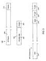
- FIG. 1is a block diagram of a prior art ATM communication network known in the art with a failed link between two nodes therein;
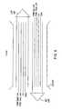
- FIG. 2is a block diagram of an ATM network incorporating therein a MPLS network according to an embodiment of the invention with a failed tunnel link between two MPLS nodes in the MPLS network;
- FIG. 3is a block diagram of two ATM cells and an equivalent MPLS frame which are utilized by a node in FIG. 2 which embodies the invention
- FIG. 4is a block diagram of a tunnel link connecting two MPLS nodes in the MPLS network of FIG. 2 ;
- FIG. 5is a flow chart of an algorithm used to establish the tunnel link of FIG. 3 ;
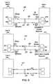
- FIG. 6is a diagram of various cases of OAM frames sent and monitored associated with the tunnel link of FIG. 4 ;
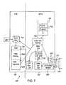
- FIG. 7is a block diagram of elements of a node embodying the invention interfacing the ATM network with the MPLS network of FIG. 2 ;
- FIG. 8is a block diagram of a MPLS OAM state machine present in the node of FIG. 7 .
- prior art system 100comprising an ATM network whose general configuration is known in the art.
- network 102comprises an interconnected number ATM switches 104 connected by communication links 106 which can each carry ATM traffic thereon.
- ATM edge switch 108provides a connection for Customer Premise Equipment (CPE) 110 to network 102 .
- CPECustomer Premise Equipment
- ATM edge switch 112provides a link for CPE 114 to network cloud 102 .
- ATM edge switch 108may also have a connection to another ATM network 116 .
- ATM edge switch 108is connected to elements in network 102 via link 118 .
- ATM edge switch 112is connected to elements in network 102 via link 120 .
- ATM edges switcheshave the ability to detect and reroute around failures in network cloud 102 , using known PNNI signalling or ATM OAM protocols.
- PNNI signalling linkfirst is established from ATM edge switch 108 to ATM edge switch 112 through ATM switches 104 .
- routing path 122 traversing ATM switches 104 A, 104 B and 104 Cis established.
- PNNIcan be used to re-establish a connection along an alternate path.
- the embodimentprovides a system and method for a node having a connection to an ATM network and a connection to a MPLS network to detect and reroute around failures in established paths detected in the MPLS network utilizing MPLS OAM. Further detail on the embodiment utilizing a MPLS network is provided.
- system 200which includes a switch incorporating an embodiment.
- MPLS network 202comprises MPLS switches 204 which are linked via communication links 206 .
- ATM/MPLS switch 208provides and interface for ATM devices such as CPE 210 to network 202 .
- ATM/MPLS switch 212provides an interface point for an ATM device such as CPE 214 .
- ATM/MPLS switch 208has a link to another ATM network 216 .
- ATM/MPLS switch 208communicates with MPLS switches in network 202 via communication link 218 .
- ATM/MPLS switch 212communicates with MPLS switch 204 C via communication link 220 .
- network 202may have other connections to other networks.
- the MPLS switches 208utilize MPLS signalling to establish dedicated and preset routing paths for traffic carried within MPLS network 202 .
- the routing pathsare known to all elements in network 202 .
- CPE 210is in communications with CPE 214
- the datais sent through MPLS network 202 using Label Switched Path (“LSP”) 222 between ATM/MPLS switch 208 and ATM/MPLS switch 212 .
- LSP 222can also carry data from switch 212 to switch 208 .
- a LSPmay also be referred to as a routing path.
- switch 208is an embodiment providing a handshaking point between ATM and MPLS networks allowing routing information from each type of network to be provided and used by the other network in maintaining communication links. It will appreciated that switch 208 may also be referred to as a node, network element, routing switch or other terms known in the art.
- ATM/MPLS switch 208is notionally at edge of an ATM network and an MPLS network
- ATM/MPLS switch 208must translate ATM cells to MPLS frames and vice versa.
- ATM datais either encapsulated into cells or frames.
- Exemplary ATM cell 300comprises 48 bytes of data in data field 302 and five bytes of header data in header field 304 .
- the header fieldincludes data relating to error checking destination information.
- ATM cells 300are used to encode voice calls in AAL 1/2/5 signalling parameters.
- ATM framesare used to transmit larger amounts of data.
- Exemplary ATM frame 306comprises data field 308 which may have 65 Kbytes of data. Header field 312 is comparable to header field 304 for ATM cell 304 .
- MPLS framecomprises data field 314 , header field 316 , first label field 318 and second label field 320 .
- First label field 318 and second label field 320are used to identify the routing information for MPLS frame 312 through MPLS network 202 .
- First label field 318contains identification information relating to the MPLS routing path for the MPLS frame. For example this first label field 318 may contain information relating to the routing path relating to MPLS routing path 222 .
- Second label field 320contains connection information relating to the particular internal ATM connection which may be used by nodes 208 and 212 for routing the ATM path. As the tunnels are known, each node in network 202 can examine the contents of first label field 318 and direct the frame to the appropriate node in the network 202 .
- MPLS routing paths 206 , 220 and 218are physically embodied in separate fibre optic cables each carrying uni-directional data either to or from an MPLS switch 204 or ATM/MPLS switch 208 .
- MPLS routing path 218downstream communications from ATM/MPLS switch 208 to MPLS switch 204 A are carried on a separate fibre connection identified as label switched path (LSP) 400 .
- LSPlabel switched path
- communications carried from MPLS switch 204 A to ATM/MPLS switch 208are carried LSP 402 .
- LSP 400 and LSP 402may be connected to the same physical port on switch 208 which may be collectively grouped into an MPLS tunnel constituting MPLS routing path 218 . It will be appreciated that the term “tunnel” is interchangeable with the term “MPLS routing path”.
- a PNNI trunk groupis created to associate LSP 400 with LSP 402 .
- the PNNI trunk groupmay be one of many trunk groups associated with a physical port on switch 208 that interfaces to MPLS network 202 .
- the trunk groupalso allows connection admission control (CAC) and ATM signalling of ATM connections over the tunnel using PNNI signalling protocols.
- CACconnection admission control
- algorithm 500is shown which is used establish, configure and monitor a tunnel, such as MPLS routing paths 222 and 224 .
- one LSPis created per direction between the source and destination MPLS switch nodes.
- the source MPLS nodemay be ATM/MPLS switch 208 and the destination MPLS switch may be ATM/MPLS switch 212 .
- the two respective LSPsare combined to create a tunnel.
- the tunnelmay be MPLS routing path 222 .
- the PNNI signalling link associated with the ATM datais connected to the tunnel.
- the PNNI routing link associated with the ATM datais connected to the tunnel.
- tunnel monitoringis enabled.
- tunnel 222provides a communication link between ATM/MPLS edge switch 208 to ATM/MPLS switch 212 .
- the PNNI signalling and routing links in the tunnelenable the embodiment to use PNNI signalling protocols to detect and react to any signalling failures in tunnel 222 .
- the embodimentutilizes MPLS OAM signalling protocols instead of PNNI protocols as MPLS signalling protocols provide improved response times.
- algorithm 500may be repeated to establish an alternate routing path for ATM/MPLS switch 208 to ATM/MPLS switch 212 .
- LSP 400 and 402may each carry PNNI signalling link packets, PNNI routing link data packets and specialized MPLS operation, administration and maintenance (OAM) frames.
- the MPLS OAM framesfollow ITU Y.17 MPLS standards, which are incorporated herein by reference. There are three types of MPLS OAM frames used by the embodiment:
- the type of MPLS OAM frame sent within an LSPis identified via the header information and the second label field 320 in an MPLS frame.
- the first label field 318contains the tunnel identification information related to the OAM destination.
- a MPLS OAM frameis identified with a value defined by the MPLS standards bodies. Currently, the value is “5”. This value is placed in second label field 320 .
- the contents of the data fieldidentify the type of MPLS OAM frame.
- the OAM signalling protocolgenerally operates as follows: at an upstream switch, an OAM frame is generated and is transmitted in its associated LSP to a downstream switch. At the downstream switch the OAM frame is received and is analysed. Depending on the results of the analysis, the downstream switch generates a response OAM frame which is transmitted upstream to the originating switch along its associated LSP. At the originating switch, the response OAM frame is received and analysed. Depending on the state of either LSP or either switch, the ultimate response message will indicate to the originating switch the status of the entire tunnel.
- upstream switchis ATM/MPLS switch 208
- downstream switchis ATM/MPLS switch 212
- the originating frame moduleis transmit module 602
- the receiving moduleis monitoring module 604
- the reply transmit moduleis module 606
- the receiving reply moduleis monitoring module 608 .
- Case A at 600illustrates a tunnel 222 with no transmission problems in the noted elements.
- transmit modules 602generates a CV frame and transmits it on LSP 400 .
- the CV frameis received by the monitoring module 604 .
- the monitoring moduleacknowledges receipt of the CV frame.
- the response CV frameis received at switch 208 at module 608 .
- Switch 208can determine that tunnel 222 is fully operational by the receipt of the response CV frame.
- CV framesare generated by CV transmit module 602 and module 608 every one second according to ITU Y.17 standards. Accordingly, after a certain transmission and frame processing delay, when tunnel 222 and its downstream components which affect tunnel 222 are fully operational, the response CV frames received by 208 should arrive approximately once every second. It will be appreciated that other time intervals could be used for transmitting CV frames.
- Case D(not shown in FIG. 6 ) is a variation Case A.
- switch 208 and switch 212will be able to transmit and receive CV frames therebetween.
- CV/BDI/FDI response module 606generates a FDI frame, which indicates that downstream of switch 212 there is a forward integrity problem associated with tunnel 222 .
- the FDI frameis transmitted from switch 212 to switch 208 via LDP 402 .
- the FDI frameis received by CV/BDI/FDI frame monitor 608 .
- Switch 208can then recognize the fault downstream of tunnel 222 and can switch to an alternate tunnel as necessary.
- switch 208generates and inserts CV frames at one second intervals.
- a failureis noted by any receiving module only after three consecutive frames either are not received or indicate that there is a problem with the link (either through a BDI or FDI indication) to eliminate spurious error signals.
- Switch 208comprises ATM processing section 700 and MPLS processing section 702 .
- ATM section 700comprises connection maintenance module 704 and PNNI signalling module 706 .
- ATM section 700may reside in a central control module of switch 108 .
- MPLS processing section 702comprises CV frame generator and transmitter 603 and CV/BDI/FDI monitor 608 , MPLS connection control module 708 , and MPLS OAM state machine 710 .
- CV transmitter module 602 and CV/BDI/FDI monitor 608connect to physical port 712 which connects to tunnel 218 and operate as described earlier.
- LSP management module 714provides an interface for modules in the ATM processing section 700 and the MPLS processing section 702 .
- MPLS processing section 702may reside on a line card in switch 208 . There may be several line cards in switch 108 having MPLS processing section 702 .
- MPLS OAM framesare generated by CV transmitter module 602 and sent on tunnel 218 .
- MPLS response framesare received by CV/BDI/FDI monitor 608 from tunnel 218 .
- module 608notifies OAM state machine 710 of the OAM frame.
- OAM state machine 710receives the OAM frames and determines whether the associated LSP tunnel is in a CV, BDI or FDI state.
- OAM state machine 710has three states: Unknown state 802 , OK state 804 and Defect state 806 . Upon initialization, OAM state machine 710 starts in Unknown state 802 .
- State machine 710will transition from Unknown state 802 to OK state 804 if connectivity verification of the tunnel is successful. Connectivity verification may be successful upon receipt of a consecutive number of CV packets. State machine 710 will transition from Unknown state 802 to Defect state 806 if connectivity verification fails or if a BDI or FDI packet is received. In performing connectivity verification, CV packets should be received by OAM state machine 710 periodically, about once every second. However, after a period of time has elapsed without receiving a CV packet, OAM state machine 710 moves to Defect state 806 . In the embodiment, the LSP tunnel is in a CV failure state if CV packets are not received in a window of approximately three seconds. When initially in Unknown state 802 and state machine 710 receives either a BDI packet or an FDI, state machine 710 moves to Defect state 806 .
- the defectcan be cleared. If the defect was caused by an absence of a CV packet, then the defect is cleared if state machine 710 receives a series of consecutive CV packets. The number of packets may be configurable. If the defect was caused by the receipt of either a BDI or an FDI packet, then the defect may be cleared if state machine does not receive a further BDI (or FDI) packet within a defined period of time. The defined period of time may be varied by the state machine 710 . Upon the clearing of a defect, state machine 710 moves to OK state 804 .
- OAM state machine 710signals the status of the tunnel 218 to LSP management module 714 via generating and enqueing a Change of State entry 716 of Change FIFO 718 .
- the entry 716contains information about the destination LSP and MPLS OAM status information, i.e. information relating to the status of the CV, BDI and FDI frames.
- LSP management module 714periodically monitors FIFO 718 for new entries. Upon detection of a new entry therein, LSP management module 714 identifies which LSP failed and signals ATM signalling module 706 with a message identifying that there is a “link down” for the LSP.
- ATM signalling module 706manages ATM signal connections and process messages indicating the availability of tunnels to contain ATM connections, such as any “link down” messages from LSP management module 714 .
- Signalling module 706is associated with PNNI routing module 706 A and PNNI signalling module 706 B.
- PNNI routing module 706 Ahas access to tables and databases for all routing paths known to switch 108 , including paths through network 202 , which as such include paths 222 and 224 .
- PNNI signalling module 706 Bmanages messaging to establish and clear connections. When a “link down” message is received, routing module 706 A determines an alternate path to the failed link. Once routing module 706 A decides upon the alternate path, it advises signalling module 706 B of the new routing change. Signalling module 706 B sends a message to connection maintenance module 704 with the new signalling information. This new signalling information can be used when routing ATM traffic from CPE 210 .
- Signalling module 706 Balso notifies MPLS connection control module 708 of the new PNNI information. Accordingly, signalling module 706 B can signal a call from node 208 to node 212 using an ATM signalling protocol (e.g. PNNI). During this exchange, the values for second label 320 are negotiated using PNNI.
- an ATM signalling protocole.g. PNNI
- connection control module 708notifies it to tear down the connection for the failed tunnel and establish a new MPLS route over the alternate tunnel. For example, referring to FIG. 2 , upon a failure of path 222 , alternate path 224 may be selected. Routing information about the new path is also provided to MPLS connection control module 704 by PNNI routing module 706 A. Routing module 706 A has knowledge of all paths, including all tunnels and the status of all tunnels. MPLS connection control module 708 then determines the new label information for first label 318 and second label 320 when sending its appropriate data and CV frames out on connection 218 . In connection control module 708 , stack 720 comprising entries 722 of second label fields is used to track primary and alternate MPLS routing paths. The stack provides a pre-formed list of labels which can be used by connection control module 704 allowing an efficient mechanism for identifying new labels for alternate routes once it is determined that the current MPLS route is no longer viable.
- the use of the MPLS CV OAM framesprovides a fault resolution of signals which should be received every second by the MPLS modules in switch 208 .
- Thiscompares favourably with the typical PNNI signalling scheme which provides resolution of failures once every 30 seconds and ATM signalling schemes which provides resolution of information only once every 60 seconds.
- switch 208stops receiving CV frames. Accordingly, OAM state machines 710 does not receive CV frames. After three consecutive missed frames i.e., three seconds, state machines 710 determines that the LSP tunnel has failed. In response, state machine 710 sends an MPLS OAM CV Failure Detected Message to LSP management modules 714 .
- LSP management module 714receives the Failure Detected Message and generates and sends a “link down” message to the ATM signalling system 708 .
- the ATM signalling module 708receives the “link down” message. Accordingly, each ATM connection that was previously using the failed link now cannot pass data.
- the ATM signalling module 708sends a “remove connection” to MPLS connection control module 704 to remove the MPLS connection.
- the ATM signalling module 708marks the current failed LSP tunnel 400 as not being available for new ATM connections.
- MPLS connection control module 704receives the “remove connection” message. It programs the CV transmitter 602 to stop forwarding-frames to the failed LSP tunnel 400 by changing the destination information in First Label Field 318 ( FIG. 3 ).
- the ATM signalling module 708reroutes the ATM connection across the other operational LSP tunnel.
- ATM signalling module 708 Bsends an “add connection” message to the MPLS connection control module 704 to enable the alternate tunnel 224 to be associated with the ATM traffic.
- Second OAM state machine 710sends a “CV failure cleared” message to the LSP management module 714 by enqueing an appropriate message in FIFO 718 .
- LSP management module 714receives the “CV failure cleared” message and determines that the previously failed LSP is now operational. Accordingly it sends a “link up” message to the ATM signalling module 706 B.
- ATM signalling module 706 Breceives the “link up” message. It marks the previously failed tunnel as now being available for new ATM connections. A further signal may be provided to connection control module 708 to re-use the previously failed tunnel.
Landscapes
- Engineering & Computer Science (AREA)
- Computer Networks & Wireless Communication (AREA)
- Signal Processing (AREA)
- Environmental & Geological Engineering (AREA)
- Data Exchanges In Wide-Area Networks (AREA)
Abstract
Description
Claims (24)
Priority Applications (1)
| Application Number | Priority Date | Filing Date | Title |
|---|---|---|---|
| US11/635,534US7778163B2 (en) | 2001-12-17 | 2006-12-08 | System and method for detecting failures and re-routing connections in a communication network |
Applications Claiming Priority (2)
| Application Number | Priority Date | Filing Date | Title |
|---|---|---|---|
| US10/015,573US7164652B2 (en) | 2001-12-17 | 2001-12-17 | System and method for detecting failures and re-routing connections in a communication network |
| US11/635,534US7778163B2 (en) | 2001-12-17 | 2006-12-08 | System and method for detecting failures and re-routing connections in a communication network |
Related Parent Applications (1)
| Application Number | Title | Priority Date | Filing Date |
|---|---|---|---|
| US10/015,573ContinuationUS7164652B2 (en) | 2001-12-17 | 2001-12-17 | System and method for detecting failures and re-routing connections in a communication network |
Publications (2)
| Publication Number | Publication Date |
|---|---|
| US20070081465A1 US20070081465A1 (en) | 2007-04-12 |
| US7778163B2true US7778163B2 (en) | 2010-08-17 |
Family
ID=21772210
Family Applications (2)
| Application Number | Title | Priority Date | Filing Date |
|---|---|---|---|
| US10/015,573Expired - Fee RelatedUS7164652B2 (en) | 2001-12-17 | 2001-12-17 | System and method for detecting failures and re-routing connections in a communication network |
| US11/635,534Expired - Fee RelatedUS7778163B2 (en) | 2001-12-17 | 2006-12-08 | System and method for detecting failures and re-routing connections in a communication network |
Family Applications Before (1)
| Application Number | Title | Priority Date | Filing Date |
|---|---|---|---|
| US10/015,573Expired - Fee RelatedUS7164652B2 (en) | 2001-12-17 | 2001-12-17 | System and method for detecting failures and re-routing connections in a communication network |
Country Status (3)
| Country | Link |
|---|---|
| US (2) | US7164652B2 (en) |
| EP (1) | EP1324568A3 (en) |
| CN (1) | CN100429889C (en) |
Families Citing this family (114)
| Publication number | Priority date | Publication date | Assignee | Title |
|---|---|---|---|---|
| US7164652B2 (en)* | 2001-12-17 | 2007-01-16 | Alcatel Canada Inc. | System and method for detecting failures and re-routing connections in a communication network |
| EP1500236B1 (en)* | 2002-04-29 | 2008-05-07 | Nokia Siemens Networks Gmbh & Co. Kg | Method for monitoring the transmission quality of connections in mpls networks |
| JP3957065B2 (en)* | 2002-08-28 | 2007-08-08 | 富士通株式会社 | Network computer system and management device |
| FI122373B (en)* | 2002-10-24 | 2011-12-30 | Tellabs Oy | Procedure, arrangement and network elements detect a connection error |
| US7769873B1 (en) | 2002-10-25 | 2010-08-03 | Juniper Networks, Inc. | Dynamically inserting filters into forwarding paths of a network device |
| US7702810B1 (en)* | 2003-02-03 | 2010-04-20 | Juniper Networks, Inc. | Detecting a label-switched path outage using adjacency information |
| US7839891B1 (en)* | 2003-03-11 | 2010-11-23 | Nortel Networks Limited | Method for using a knowledge digest to verify configuration information in a network |
| US8296407B2 (en)* | 2003-03-31 | 2012-10-23 | Alcatel Lucent | Calculation, representation, and maintenance of sharing information in mesh networks |
| US7606237B2 (en)* | 2003-03-31 | 2009-10-20 | Alcatel-Lucent Usa Inc. | Sharing restoration path bandwidth in mesh networks |
| US7545736B2 (en)* | 2003-03-31 | 2009-06-09 | Alcatel-Lucent Usa Inc. | Restoration path calculation in mesh networks |
| US8867333B2 (en)* | 2003-03-31 | 2014-10-21 | Alcatel Lucent | Restoration path calculation considering shared-risk link groups in mesh networks |
| US7689693B2 (en)* | 2003-03-31 | 2010-03-30 | Alcatel-Lucent Usa Inc. | Primary/restoration path calculation in mesh networks based on multiple-cost criteria |
| US7646706B2 (en)* | 2003-03-31 | 2010-01-12 | Alcatel-Lucent Usa Inc. | Restoration time in mesh networks |
| US7643408B2 (en)* | 2003-03-31 | 2010-01-05 | Alcatel-Lucent Usa Inc. | Restoration time in networks |
| US7451340B2 (en)* | 2003-03-31 | 2008-11-11 | Lucent Technologies Inc. | Connection set-up extension for restoration path establishment in mesh networks |
| US7561527B1 (en)* | 2003-05-02 | 2009-07-14 | David Katz | Bidirectional forwarding detection |
| DE602004025105D1 (en)* | 2003-05-27 | 2010-03-04 | Ibm | SYSTEM FOR DETERMINING AN ALTERNATIVE PATH IN A MESSAGING MIDDLEWARE ENVIRONMENT |
| US8078758B1 (en) | 2003-06-05 | 2011-12-13 | Juniper Networks, Inc. | Automatic configuration of source address filters within a network device |
| US7500013B2 (en)* | 2004-04-02 | 2009-03-03 | Alcatel-Lucent Usa Inc. | Calculation of link-detour paths in mesh networks |
| US8111612B2 (en)* | 2004-04-02 | 2012-02-07 | Alcatel Lucent | Link-based recovery with demand granularity in mesh networks |
| US20050226212A1 (en)* | 2004-04-02 | 2005-10-13 | Dziong Zbigniew M | Loop avoidance for recovery paths in mesh networks |
| US7856509B1 (en) | 2004-04-09 | 2010-12-21 | Juniper Networks, Inc. | Transparently providing layer two (L2) services across intermediate computer networks |
| US7965620B2 (en)* | 2004-05-25 | 2011-06-21 | Telcordia Licensing Company, Llc | Method, computer product and system for correlating events in a network |
| US8160076B1 (en) | 2004-08-30 | 2012-04-17 | Juniper Networks, Inc. | Auto-discovery of multicast virtual private networks |
| US7489695B1 (en) | 2004-10-12 | 2009-02-10 | Juniper Networks, Inc. | Automatic LSP stitching with protocol signaling |
| US7539158B2 (en) | 2004-11-08 | 2009-05-26 | Lemko Corporation | System, method and device for providing communications using a distributed mobile architecture |
| CN100366118C (en)* | 2004-11-17 | 2008-01-30 | 华为技术有限公司 | A maintenance link detection and recovery method |
| CN100417080C (en)* | 2005-02-01 | 2008-09-03 | 华为技术有限公司 | A method for detecting network link faults and locating faults |
| US7602702B1 (en)* | 2005-02-10 | 2009-10-13 | Juniper Networks, Inc | Fast reroute of traffic associated with a point to multi-point network tunnel |
| CN100389571C (en)* | 2005-03-25 | 2008-05-21 | 华为技术有限公司 | Method for detecting chain circuit fault between end-to-end notes in mixed network |
| CN100403687C (en)* | 2005-03-29 | 2008-07-16 | 华为技术有限公司 | Method for Realizing Domain-Divided Management and Protection in Multi-protocol Label Switching Network |
| US8730814B2 (en)* | 2005-05-25 | 2014-05-20 | Alcatel Lucent | Communication network connection failure protection methods and systems |
| US9166807B2 (en)* | 2005-07-28 | 2015-10-20 | Juniper Networks, Inc. | Transmission of layer two (L2) multicast traffic over multi-protocol label switching networks |
| US7990965B1 (en) | 2005-07-28 | 2011-08-02 | Juniper Networks, Inc. | Transmission of layer two (L2) multicast traffic over multi-protocol label switching networks |
| US7564803B1 (en) | 2005-08-29 | 2009-07-21 | Juniper Networks, Inc. | Point to multi-point label switched paths with label distribution protocol |
| KR100696176B1 (en)* | 2005-12-09 | 2007-03-20 | 한국전자통신연구원 | MPS LSP Protection Alternating Device and Method |
| US7715307B2 (en)* | 2005-12-13 | 2010-05-11 | Alcatel Lucent | Communication connection control systems and methods |
| US8089865B2 (en)* | 2006-01-25 | 2012-01-03 | Hitachi, Ltd. | Multicast path management and protection |
| US8270395B2 (en)* | 2006-01-30 | 2012-09-18 | Juniper Networks, Inc. | Forming multicast distribution structures using exchanged multicast optimization data |
| US7839850B2 (en)* | 2006-01-30 | 2010-11-23 | Juniper Networks, Inc. | Forming equal cost multipath multicast distribution structures |
| US7856233B2 (en) | 2006-03-30 | 2010-12-21 | Lemko Corporation | System, method, and device for providing communications using a distributed mobile architecture |
| CN1852183A (en)* | 2006-04-18 | 2006-10-25 | 华为技术有限公司 | Method and apparatus for detecting counter defect indication-path condition |
| CN100456697C (en)* | 2006-04-20 | 2009-01-28 | 华为技术有限公司 | An automatic configuration method and system for bidirectional forwarding detection |
| US8224322B2 (en) | 2006-06-12 | 2012-07-17 | Lemko Corporation | Roaming mobile subscriber registration in a distributed mobile architecture |
| CN100459531C (en)* | 2006-06-28 | 2009-02-04 | 华为技术有限公司 | Method for notifying pseudo-lines fault based on bidirectional transmission detecting protocol |
| US7839862B1 (en) | 2006-06-30 | 2010-11-23 | Juniper Networks, Inc. | Upstream label assignment for the label distribution protocol |
| US7742482B1 (en) | 2006-06-30 | 2010-06-22 | Juniper Networks, Inc. | Upstream label assignment for the resource reservation protocol with traffic engineering |
| US7787380B1 (en) | 2006-06-30 | 2010-08-31 | Juniper Networks, Inc. | Resource reservation protocol with traffic engineering point to multi-point label switched path hierarchy |
| US8676197B2 (en) | 2006-12-13 | 2014-03-18 | Lemko Corporation | System, method, and device to control wireless communications |
| US7724676B2 (en)* | 2007-03-21 | 2010-05-25 | Cisco Technology, Inc. | Proactive protection mechanism based on advanced failure warning |
| US8472325B2 (en) | 2007-05-10 | 2013-06-25 | Futurewei Technologies, Inc. | Network availability enhancement technique for packet transport networks |
| CN101316225B (en)* | 2007-05-30 | 2012-12-12 | 华为技术有限公司 | Fault detection method, communication system and label exchange router |
| CN101355442B (en)* | 2007-07-24 | 2011-07-06 | 华为技术有限公司 | A method for presenting server and state transition of its subscription state machine |
| US8040792B2 (en)* | 2007-08-02 | 2011-10-18 | Foundry Networks, Llc | Techniques for determining local repair connections |
| US8711676B2 (en) | 2007-08-02 | 2014-04-29 | Foundry Networks, Llc | Techniques for determining optimized local repair paths |
| US8108545B2 (en) | 2007-08-27 | 2012-01-31 | International Business Machines Corporation | Packet coalescing in virtual channels of a data processing system in a multi-tiered full-graph interconnect architecture |
| US7904590B2 (en) | 2007-08-27 | 2011-03-08 | International Business Machines Corporation | Routing information through a data processing system implementing a multi-tiered full-graph interconnect architecture |
| US7793158B2 (en)* | 2007-08-27 | 2010-09-07 | International Business Machines Corporation | Providing reliability of communication between supernodes of a multi-tiered full-graph interconnect architecture |
| US7840703B2 (en)* | 2007-08-27 | 2010-11-23 | International Business Machines Corporation | System and method for dynamically supporting indirect routing within a multi-tiered full-graph interconnect architecture |
| US8014387B2 (en)* | 2007-08-27 | 2011-09-06 | International Business Machines Corporation | Providing a fully non-blocking switch in a supernode of a multi-tiered full-graph interconnect architecture |
| US7958183B2 (en) | 2007-08-27 | 2011-06-07 | International Business Machines Corporation | Performing collective operations using software setup and partial software execution at leaf nodes in a multi-tiered full-graph interconnect architecture |
| US7958182B2 (en) | 2007-08-27 | 2011-06-07 | International Business Machines Corporation | Providing full hardware support of collective operations in a multi-tiered full-graph interconnect architecture |
| US7822889B2 (en)* | 2007-08-27 | 2010-10-26 | International Business Machines Corporation | Direct/indirect transmission of information using a multi-tiered full-graph interconnect architecture |
| US7809970B2 (en)* | 2007-08-27 | 2010-10-05 | International Business Machines Corporation | System and method for providing a high-speed message passing interface for barrier operations in a multi-tiered full-graph interconnect architecture |
| US7769891B2 (en)* | 2007-08-27 | 2010-08-03 | International Business Machines Corporation | System and method for providing multiple redundant direct routes between supernodes of a multi-tiered full-graph interconnect architecture |
| US8185896B2 (en) | 2007-08-27 | 2012-05-22 | International Business Machines Corporation | Method for data processing using a multi-tiered full-graph interconnect architecture |
| US8140731B2 (en) | 2007-08-27 | 2012-03-20 | International Business Machines Corporation | System for data processing using a multi-tiered full-graph interconnect architecture |
| US7769892B2 (en) | 2007-08-27 | 2010-08-03 | International Business Machines Corporation | System and method for handling indirect routing of information between supernodes of a multi-tiered full-graph interconnect architecture |
| US7827428B2 (en) | 2007-08-31 | 2010-11-02 | International Business Machines Corporation | System for providing a cluster-wide system clock in a multi-tiered full-graph interconnect architecture |
| US7921316B2 (en) | 2007-09-11 | 2011-04-05 | International Business Machines Corporation | Cluster-wide system clock in a multi-tiered full-graph interconnect architecture |
| US8358576B2 (en) | 2007-10-03 | 2013-01-22 | Foundry Networks, Llc | Techniques for determining local repair paths using CSPF |
| US8125926B1 (en) | 2007-10-16 | 2012-02-28 | Juniper Networks, Inc. | Inter-autonomous system (AS) virtual private local area network service (VPLS) |
| US7779148B2 (en) | 2008-02-01 | 2010-08-17 | International Business Machines Corporation | Dynamic routing based on information of not responded active source requests quantity received in broadcast heartbeat signal and stored in local data structure for other processor chips |
| US8077602B2 (en)* | 2008-02-01 | 2011-12-13 | International Business Machines Corporation | Performing dynamic request routing based on broadcast queue depths |
| US20090198956A1 (en)* | 2008-02-01 | 2009-08-06 | Arimilli Lakshminarayana B | System and Method for Data Processing Using a Low-Cost Two-Tier Full-Graph Interconnect Architecture |
| US7936780B1 (en) | 2008-03-12 | 2011-05-03 | Juniper Networks, Inc. | Hierarchical label distribution protocol for computer networks |
| US8046420B2 (en) | 2008-04-23 | 2011-10-25 | Lemko Corporation | System and method to control wireless communications |
| US8340667B2 (en) | 2008-06-26 | 2012-12-25 | Lemko Corporation | System and method to control wireless communications |
| US8706105B2 (en)* | 2008-06-27 | 2014-04-22 | Lemko Corporation | Fault tolerant distributed mobile architecture |
| US8107409B2 (en) | 2008-07-11 | 2012-01-31 | Lemko Corporation | OAMP for distributed mobile architecture |
| US7855988B2 (en) | 2008-07-14 | 2010-12-21 | Lemko Corporation | System, method, and device for routing calls using a distributed mobile architecture |
| WO2010023510A1 (en)* | 2008-08-26 | 2010-03-04 | Alcatel Lucent | Methods for establishing a traffic connection and an associated monitoring connection |
| US7979066B2 (en) | 2008-09-25 | 2011-07-12 | Lemko Corporation | Multiple IMSI connections |
| US7929557B2 (en)* | 2008-11-14 | 2011-04-19 | Juniper Networks, Inc. | Summarization and longest-prefix match within MPLS networks |
| US8077726B1 (en) | 2008-12-10 | 2011-12-13 | Juniper Networks, Inc. | Fast reroute for multiple label switched paths sharing a single interface |
| US8630164B2 (en)* | 2009-08-04 | 2014-01-14 | At&T Intellectual Property I, L.P. | Methods and apparatus to respond to signaling protocol failures in traffic engineering tunnels |
| EP2507942B1 (en) | 2009-12-01 | 2017-05-17 | Telefonaktiebolaget LM Ericsson (publ) | Fault monitoring in connection-oriented networks |
| US8417778B2 (en)* | 2009-12-17 | 2013-04-09 | International Business Machines Corporation | Collective acceleration unit tree flow control and retransmit |
| US8422514B1 (en) | 2010-02-09 | 2013-04-16 | Juniper Networks, Inc. | Dynamic configuration of cross-domain pseudowires |
| EP2537295A1 (en)* | 2010-02-19 | 2012-12-26 | Nokia Siemens Networks Oy | Method and device for conveying oam messages across an inter-carrier network |
| US8406243B2 (en)* | 2010-02-22 | 2013-03-26 | Telefonaktiebolaget L M Ericsson (Publ) | Fast LSP alert mechanism |
| US8467289B2 (en)* | 2010-02-22 | 2013-06-18 | Telefonaktiebolaget L M Ericsson (Publ) | Optimized fast re-route in MPLS ring topologies |
| US8310957B1 (en) | 2010-03-09 | 2012-11-13 | Juniper Networks, Inc. | Minimum-cost spanning trees of unicast tunnels for multicast distribution |
| US8976680B2 (en)* | 2010-03-15 | 2015-03-10 | Juniper Networks, Inc. | Operations, administration, and management fields for packet transport |
| US8588081B2 (en)* | 2010-07-14 | 2013-11-19 | Cisco Technology, Inc. | Monitoring a flow set to detect faults |
| US8850062B2 (en)* | 2010-08-09 | 2014-09-30 | Cisco Technology, Inc. | Distributed connectivity verification protocol redundancy |
| EP2461501A1 (en)* | 2010-12-01 | 2012-06-06 | Alcatel Lucent | Tunnel follow-up message for transparent clock |
| US9246838B1 (en) | 2011-05-27 | 2016-01-26 | Juniper Networks, Inc. | Label switched path setup using fast reroute bypass tunnel |
| US9100213B1 (en) | 2011-06-08 | 2015-08-04 | Juniper Networks, Inc. | Synchronizing VPLS gateway MAC addresses |
| US9356859B2 (en) | 2011-08-16 | 2016-05-31 | Brocade Communications Systems, Inc. | Techniques for performing a failover from a protected connection to a backup connection |
| JP5975037B2 (en)* | 2011-09-27 | 2016-08-23 | 日本電気株式会社 | Communication system, communication apparatus, failure notification method, and program |
| CN103765816A (en) | 2011-09-28 | 2014-04-30 | 惠普发展公司,有限责任合伙企业 | Managing a switch fabric |
| US9479391B2 (en) | 2011-09-28 | 2016-10-25 | Hewlett Packard Enterprise Development Lp | Implementing a switch fabric responsive to an unavailable path |
| US9391833B2 (en)* | 2011-11-23 | 2016-07-12 | Verizon Patent And Licensing Inc. | Fault signaling for ethernet |
| US8837479B1 (en) | 2012-06-27 | 2014-09-16 | Juniper Networks, Inc. | Fast reroute between redundant multicast streams |
| US9049148B1 (en) | 2012-09-28 | 2015-06-02 | Juniper Networks, Inc. | Dynamic forwarding plane reconfiguration in a network device |
| US20140258772A1 (en)* | 2013-03-07 | 2014-09-11 | Fujitsu Limited | Utilizing backward defect indications in y-cable protection switching |
| US8953500B1 (en) | 2013-03-29 | 2015-02-10 | Juniper Networks, Inc. | Branch node-initiated point to multi-point label switched path signaling with centralized path computation |
| US9806895B1 (en) | 2015-02-27 | 2017-10-31 | Juniper Networks, Inc. | Fast reroute of redundant multicast streams |
| CN107086956A (en)* | 2017-05-27 | 2017-08-22 | 烽火通信科技股份有限公司 | A kind of implementation method of Ethernet pretection switch |
| US10469367B2 (en) | 2017-10-04 | 2019-11-05 | Cisco Technology, Inc. | Segment routing network processing of packets including operations signaling and processing of packets in manners providing processing and/or memory efficiencies |
| WO2020151814A1 (en)* | 2019-01-23 | 2020-07-30 | Siemens Aktiengesellschaft | Method for fail-safe data transmission, network nodes, computer program and computer-readable medium |
| CN109901049B (en)* | 2019-01-29 | 2021-05-04 | 厦门码灵半导体技术有限公司 | Method and device for detecting asynchronous path in time sequence path for integrated circuit |
| US11588547B2 (en)* | 2020-10-28 | 2023-02-21 | Huawei Technologies Co., Ltd. | Seam abstraction in communications networks |
Citations (9)
| Publication number | Priority date | Publication date | Assignee | Title |
|---|---|---|---|---|
| US5627822A (en)* | 1994-05-11 | 1997-05-06 | Siemens Aktiengesellschaft | Method and circuit arrangement for disturbance-free redirection of a message cell stream onto an alternate route |
| CN1193246A (en) | 1996-12-18 | 1998-09-16 | 日本电气株式会社 | Radio selective-paging receiver with wide-area function |
| US6011780A (en)* | 1997-05-23 | 2000-01-04 | Stevens Institute Of Technology | Transparant non-disruptable ATM network |
| US20020112072A1 (en)* | 2001-02-12 | 2002-08-15 | Maple Optical Systems, Inc. | System and method for fast-rerouting of data in a data communication network |
| US6775239B1 (en)* | 1999-10-29 | 2004-08-10 | Fujitsu Limited | Checking communication-path data in MPLS communication scheme |
| US20040202112A1 (en)* | 2001-03-28 | 2004-10-14 | Mcallister Shawn P. | Method and apparatus for rerouting a connection in a data communication network based on a user connection monitoring function |
| US7002906B1 (en)* | 1998-08-28 | 2006-02-21 | Cisco Technology, Inc. | Method for extending the crankback procedure to any Asynchronous Transfer Mode system |
| US7164652B2 (en)* | 2001-12-17 | 2007-01-16 | Alcatel Canada Inc. | System and method for detecting failures and re-routing connections in a communication network |
| US7289428B2 (en)* | 2001-08-13 | 2007-10-30 | Tellabs Operations, Inc. | Inter-working mesh telecommunications networks |
Family Cites Families (5)
| Publication number | Priority date | Publication date | Assignee | Title |
|---|---|---|---|---|
| US6064650A (en)* | 1996-06-27 | 2000-05-16 | Xerox Corporation | Rate shaping in per-flow output queued routing mechanisms having output links servicing multiple physical layers |
| US5926459A (en)* | 1996-06-27 | 1999-07-20 | Xerox Corporation | Rate shaping in per-flow queued routing mechanisms for available bit rate service |
| JP3435293B2 (en)* | 1996-09-10 | 2003-08-11 | 株式会社東芝 | Packet scheduling apparatus and packet transfer method |
| US6094435A (en)* | 1997-06-30 | 2000-07-25 | Sun Microsystems, Inc. | System and method for a quality of service in a multi-layer network element |
| US6072772A (en)* | 1998-01-12 | 2000-06-06 | Cabletron Systems, Inc. | Method for providing bandwidth and delay guarantees in a crossbar switch with speedup |
- 2001
- 2001-12-17USUS10/015,573patent/US7164652B2/ennot_activeExpired - Fee Related
- 2002
- 2002-12-10EPEP02293053Apatent/EP1324568A3/ennot_activeWithdrawn
- 2002-12-16CNCNB021571449Apatent/CN100429889C/ennot_activeExpired - Fee Related
- 2006
- 2006-12-08USUS11/635,534patent/US7778163B2/ennot_activeExpired - Fee Related
Patent Citations (10)
| Publication number | Priority date | Publication date | Assignee | Title |
|---|---|---|---|---|
| US5627822A (en)* | 1994-05-11 | 1997-05-06 | Siemens Aktiengesellschaft | Method and circuit arrangement for disturbance-free redirection of a message cell stream onto an alternate route |
| CN1193246A (en) | 1996-12-18 | 1998-09-16 | 日本电气株式会社 | Radio selective-paging receiver with wide-area function |
| US6097932A (en) | 1996-12-18 | 2000-08-01 | Nec Corporation | Radio selective calling receiver having multiarea function and a reception restoring method |
| US6011780A (en)* | 1997-05-23 | 2000-01-04 | Stevens Institute Of Technology | Transparant non-disruptable ATM network |
| US7002906B1 (en)* | 1998-08-28 | 2006-02-21 | Cisco Technology, Inc. | Method for extending the crankback procedure to any Asynchronous Transfer Mode system |
| US6775239B1 (en)* | 1999-10-29 | 2004-08-10 | Fujitsu Limited | Checking communication-path data in MPLS communication scheme |
| US20020112072A1 (en)* | 2001-02-12 | 2002-08-15 | Maple Optical Systems, Inc. | System and method for fast-rerouting of data in a data communication network |
| US20040202112A1 (en)* | 2001-03-28 | 2004-10-14 | Mcallister Shawn P. | Method and apparatus for rerouting a connection in a data communication network based on a user connection monitoring function |
| US7289428B2 (en)* | 2001-08-13 | 2007-10-30 | Tellabs Operations, Inc. | Inter-working mesh telecommunications networks |
| US7164652B2 (en)* | 2001-12-17 | 2007-01-16 | Alcatel Canada Inc. | System and method for detecting failures and re-routing connections in a communication network |
Non-Patent Citations (6)
| Title |
|---|
| "MPLS Wide-Band Network Interconnection Technique", English Abstract for "MPLS Document in Chinese", Apr. 2001, 1 Page. |
| Alcatel, "ATM in the Next Generation Network-ATM-MPLS Mediation", Alcatel Technical White Paper, Aug. 31, 2001, pp. 1-16. |
| Hagard et al, "Multiprotocol Label Switching in ATM Networks", Ericsson Review, No. 1, Jan. 1, 1998, pp. 32-39. |
| MPLS Document in Chinese, Apr. 2001, 3 Pages. |
| Nippon Electric Co., English Abstract for CN 1193246 Application, Sep. 16, 1998, 1 Page. |
| The ATM Forum Technical Committee, "ATM-MPLS Network Interworking, Version 1.0, AF-AIC-0178.000", Aug. 2001, 23 Pages. |
Also Published As
| Publication number | Publication date |
|---|---|
| EP1324568A3 (en) | 2009-12-23 |
| US7164652B2 (en) | 2007-01-16 |
| US20030112748A1 (en) | 2003-06-19 |
| CN100429889C (en) | 2008-10-29 |
| CN1427581A (en) | 2003-07-02 |
| EP1324568A2 (en) | 2003-07-02 |
| US20070081465A1 (en) | 2007-04-12 |
Similar Documents
| Publication | Publication Date | Title |
|---|---|---|
| US7778163B2 (en) | System and method for detecting failures and re-routing connections in a communication network | |
| US7596094B2 (en) | System and method for transmission of operations, administration, and maintenance packets between ATM and switching networks upon failures | |
| KR100540408B1 (en) | Truncated Connection Detection Method and Apparatus Using Next Hop Loopback | |
| US6925054B1 (en) | Network path protection | |
| US6011780A (en) | Transparant non-disruptable ATM network | |
| US7180866B1 (en) | Rerouting in connection-oriented communication networks and communication systems | |
| US6538987B1 (en) | Rapid ring protection switching system | |
| EP1201100B1 (en) | Method and apparatus for fast reroute in a connection-oriented network | |
| US8971189B2 (en) | Label switched path OAM wrapper | |
| US6654923B1 (en) | ATM group protection switching method and apparatus | |
| US8737203B2 (en) | Method for establishing an MPLS data network protection pathway | |
| US7298693B1 (en) | Reverse notification tree for data networks | |
| US20040109687A1 (en) | Fast rerouting method through generalized multi-protocol label switching | |
| US20070271484A1 (en) | Method, system and network entity for detecting a connection fault | |
| US20080304407A1 (en) | Efficient Protection Mechanisms For Protecting Multicast Traffic in a Ring Topology Network Utilizing Label Switching Protocols | |
| US20030112761A1 (en) | Method for resilient call setup through ATM networks for Softswitch applications | |
| CN101523803A (en) | Resiliency schemes in communications networks | |
| US20020035640A1 (en) | Recovery method for an optical network | |
| US6859430B1 (en) | Protection switching of virtual connections | |
| US6940810B1 (en) | Protection switching of virtual connections at the data link layer | |
| Harrison et al. | Protection and restoration in MPLS networks | |
| US6990066B1 (en) | Method for using a pre-configured ATM switch and traffic discard to facilitate UPSR selection | |
| JP2001223727A (en) | Multi-ring path switching method | |
| Enfield | PROTECTION AND RESTORATION IN MPLS NETWORKS | |
| JPH10276215A (en) | Switch node |
Legal Events
| Date | Code | Title | Description |
|---|---|---|---|
| AS | Assignment | Owner name:ALCATEL LUCENT, FRANCE Free format text:ASSIGNMENT OF ASSIGNORS INTEREST;ASSIGNORS:PUPPA, GARY J.;DUBUC, KEN;MAXWELL, DAVID J.;AND OTHERS;REEL/FRAME:022006/0515 Effective date:20011212 | |
| FEPP | Fee payment procedure | Free format text:PAYOR NUMBER ASSIGNED (ORIGINAL EVENT CODE: ASPN); ENTITY STATUS OF PATENT OWNER: LARGE ENTITY | |
| STCF | Information on status: patent grant | Free format text:PATENTED CASE | |
| AS | Assignment | Owner name:CREDIT SUISSE AG, NEW YORK Free format text:SECURITY AGREEMENT;ASSIGNOR:LUCENT, ALCATEL;REEL/FRAME:029821/0001 Effective date:20130130 Owner name:CREDIT SUISSE AG, NEW YORK Free format text:SECURITY AGREEMENT;ASSIGNOR:ALCATEL LUCENT;REEL/FRAME:029821/0001 Effective date:20130130 | |
| FEPP | Fee payment procedure | Free format text:PAYOR NUMBER ASSIGNED (ORIGINAL EVENT CODE: ASPN); ENTITY STATUS OF PATENT OWNER: LARGE ENTITY Free format text:PAYER NUMBER DE-ASSIGNED (ORIGINAL EVENT CODE: RMPN); ENTITY STATUS OF PATENT OWNER: LARGE ENTITY | |
| AS | Assignment | Owner name:SOUND VIEW INNOVATIONS, LLC, NEW JERSEY Free format text:ASSIGNMENT OF ASSIGNORS INTEREST;ASSIGNOR:ALCATEL LUCENT;REEL/FRAME:032086/0016 Effective date:20131223 | |
| FPAY | Fee payment | Year of fee payment:4 | |
| AS | Assignment | Owner name:ALCATEL LUCENT, FRANCE Free format text:RELEASE OF SECURITY INTEREST;ASSIGNOR:CREDIT SUISSE AG;REEL/FRAME:032536/0006 Effective date:20131223 | |
| AS | Assignment | Owner name:ALCATEL LUCENT, FRANCE Free format text:RELEASE BY SECURED PARTY;ASSIGNOR:CREDIT SUISSE AG;REEL/FRAME:033868/0001 Effective date:20140819 | |
| MAFP | Maintenance fee payment | Free format text:PAYMENT OF MAINTENANCE FEE, 8TH YEAR, LARGE ENTITY (ORIGINAL EVENT CODE: M1552) Year of fee payment:8 | |
| FEPP | Fee payment procedure | Free format text:MAINTENANCE FEE REMINDER MAILED (ORIGINAL EVENT CODE: REM.); ENTITY STATUS OF PATENT OWNER: LARGE ENTITY | |
| LAPS | Lapse for failure to pay maintenance fees | Free format text:PATENT EXPIRED FOR FAILURE TO PAY MAINTENANCE FEES (ORIGINAL EVENT CODE: EXP.); ENTITY STATUS OF PATENT OWNER: LARGE ENTITY | |
| STCH | Information on status: patent discontinuation | Free format text:PATENT EXPIRED DUE TO NONPAYMENT OF MAINTENANCE FEES UNDER 37 CFR 1.362 | |
| FP | Lapsed due to failure to pay maintenance fee | Effective date:20220817 |