US7777480B2 - Antenna Orientation Sensor - Google Patents
Antenna Orientation SensorDownload PDFInfo
- Publication number
- US7777480B2 US7777480B2US11/852,288US85228807AUS7777480B2US 7777480 B2US7777480 B2US 7777480B2US 85228807 AUS85228807 AUS 85228807AUS 7777480 B2US7777480 B2US 7777480B2
- Authority
- US
- United States
- Prior art keywords
- sensor
- antenna
- antenna orientation
- orientation sensor
- circuit board
- Prior art date
- Legal status (The legal status is an assumption and is not a legal conclusion. Google has not performed a legal analysis and makes no representation as to the accuracy of the status listed.)
- Expired - Fee Related, expires
Links
Images


Classifications
- H—ELECTRICITY
- H01—ELECTRIC ELEMENTS
- H01Q—ANTENNAS, i.e. RADIO AERIALS
- H01Q1/00—Details of, or arrangements associated with, antennas
- H01Q1/12—Supports; Mounting means
- H01Q1/18—Means for stabilising antennas on an unstable platform
- G—PHYSICS
- G01—MEASURING; TESTING
- G01C—MEASURING DISTANCES, LEVELS OR BEARINGS; SURVEYING; NAVIGATION; GYROSCOPIC INSTRUMENTS; PHOTOGRAMMETRY OR VIDEOGRAMMETRY
- G01C17/00—Compasses; Devices for ascertaining true or magnetic north for navigation or surveying purposes
- G01C17/38—Testing, calibrating, or compensating of compasses
- G—PHYSICS
- G01—MEASURING; TESTING
- G01C—MEASURING DISTANCES, LEVELS OR BEARINGS; SURVEYING; NAVIGATION; GYROSCOPIC INSTRUMENTS; PHOTOGRAMMETRY OR VIDEOGRAMMETRY
- G01C25/00—Manufacturing, calibrating, cleaning, or repairing instruments or devices referred to in the other groups of this subclass
- H—ELECTRICITY
- H01—ELECTRIC ELEMENTS
- H01Q—ANTENNAS, i.e. RADIO AERIALS
- H01Q1/00—Details of, or arrangements associated with, antennas
- H01Q1/12—Supports; Mounting means
- H01Q1/125—Means for positioning
- H—ELECTRICITY
- H01—ELECTRIC ELEMENTS
- H01Q—ANTENNAS, i.e. RADIO AERIALS
- H01Q3/00—Arrangements for changing or varying the orientation or the shape of the directional pattern of the waves radiated from an antenna or antenna system
- H01Q3/02—Arrangements for changing or varying the orientation or the shape of the directional pattern of the waves radiated from an antenna or antenna system using mechanical movement of antenna or antenna system as a whole
- H01Q3/08—Arrangements for changing or varying the orientation or the shape of the directional pattern of the waves radiated from an antenna or antenna system using mechanical movement of antenna or antenna system as a whole for varying two co-ordinates of the orientation
Definitions
- the inventionrelates to an antenna orientation sensor. More particularly the invention relates to a magnetic antenna orientation sensor, capable of self-correction for the presence of hard and soft iron effects.
- directional antennasare oriented to direct the antenna radiation pattern towards a desired direction.
- Orientation of an antennais typically performed via adjustments to the antenna mount, with respect to a fixed mounting point, to vary orientation in, for example, three axis: proper heading, roll and pitch (mechanical beam tilt).
- Orientationmay generally be performed by manual or remote controlled electro-mechanical adjustment with respect to a reference direction. Orientation may be performed upon installations that are fixed, or dynamically on an ongoing basis during antenna operation to satisfy varying directional requirements and or changes to the orientation of the antenna mount, for example where the communication target(s) are mobile and or the antenna is mounted upon a movable land, air or water vehicle.
- Magnetic direction sensorstypically provide a directional output with respect to the planetary magnetic north pole.
- a problem with magnetic direction sensorsis errors introduced by hard and soft iron effects from nearby metal, such as the mounting of the antenna upon, for example, a metal tower or vehicle. The error level introduced will vary with the location and size of the nearby metal at each installation. Further, the error magnitude may change as the selected antenna orientation varies the location and or orientation of the sensor towards and away from the nearby metal.
- Sunlight angle sensorshave been applied as an alternative to magnetic direction sensing, however these systems operate only when and where the sun is visible to the sensor and may have a significant initial reading lag time. Also, sunlight angle sensors require periodic cleaning to prevent failure of the sensor due to environmental fouling, a significant drawback where the sensor is difficult and or dangerous to access, such as when mounted atop an antenna tower.
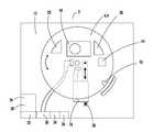
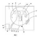
- FIG. 1is top schematic view of an exemplary antenna orientation sensor module.
- FIG. 2is a block circuit diagram demonstrating functional interconnections of antenna orientation sensor electrical circuit elements.
- FIG. 3is a network diagram for a distributed network embodiment of the invention.
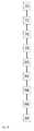
- FIG. 4is an exemplary operation sequence for the antenna orientation sensor module.
- the inventorhas recognized that, by monitoring sensor outputs along a repeatable calibration movement of the antenna orientation sensor, the hard and soft effects of nearby ferrous material may be calculated to determine a true magnetic field reference direction, thereby eliminating the hard and soft effects.
- FIG. 1An exemplary embodiment of a magnetic sensor based antenna orientation sensor in module form is shown in FIG. 1 .
- the magnetic sensor 4is movable through the calibration movement with respect to the module 2 .
- the magnetic sensor 4may be mounted upon, for example, a pivoting support 6 such as a printed circuit board (PCB) 8 movable through a calibration movement such as an arc segment via an actuator 10 coupled to a base 12 of the module 2 .
- the pivoting support 6may also carry an accelerometer 14 and or other position reporting sensor(s) 16 to identify the position of the magnetic sensor 4 as it is moved through the calibration movement.
- PCBprinted circuit board
- the magnetic sensor 4may be a three axis magnetic sensor.
- the position reporting sensor 16may be, for example, an optical sensor with respect to the base, tilt sensor, a two axis accelerometer, or a translation of the reported actuator position based upon the secondary position reporting sensor 28 , described herein below.
- Associated signal integration circuitry 18 , Global Positioning Service (GPS) circuitry 20 and or direction output calculation circuitry 22may be located on a single PCB 8 along with the magnetic sensor 4 and a position reporting sensor 16 or may alternatively be provided on a separate PCB board (not shown).
- GPSGlobal Positioning Service
- FIG. 2An example block diagram of signal integration circuitry 18 is shown in FIG. 2 .
- the three axis magnetic sensor 4delivers, for example, X, Y and Z axis analog AN 1 -AN 3 or digital inputs to a microcontroller 24 , the output of the three axis magnetic sensor 4 callable by a link between a set/reset input of the three axis magnetic sensor 4 driven from the microcontroller 24 via a digital output DO 2 .
- the position reporting sensor 16in this example a two-axis accelerometer 14 , similarly delivers X and Y digital D 10 and D 11 or analog outputs to the microcontroller 24 .
- Digital outputs D 01are applied to a relay or other control 26 that energizes the actuator 10 .
- a secondary position reporting sensor 28 of the actuator 10may be applied as a position output of the linear actuator 10 that drives an analog AN 0 or digital input of the microcontroller 24 to report, for example, the current angle of the calibration movement.
- serial data, communication control inputs and data outputs between the microcontroller 24 and a transceiver 30are transmitted/received at the microcontroller 24 TxD and RxD ports.
- the module 2also may include lightning protection 32 for the electrical circuits and a local power supply 34 . Communications and power are delivered to the module via a network interface 36 and or bus interface 38 .
- the module 2may be configured for local feedback and control or control over an extended data network 38 , as shown for example in FIG. 3 , comprising links to a plurality of devices such as communications transceivers/antennas that are mounted local to the module 2 and oriented via the feedback from the module 2 by a remote controller 42 .
- an extended data network 38as shown for example in FIG. 3 , comprising links to a plurality of devices such as communications transceivers/antennas that are mounted local to the module 2 and oriented via the feedback from the module 2 by a remote controller 42 .
- the calibration movementis performed with respect to pitch angle ⁇ and roll angle ⁇ readings obtained from the position reporting sensor 28 and a reference angle representing the position of the magnetic sensor 4 along the arc of the calibration movement.
- the magnetic sensor 4 outputsare designated as x, y, and z, with x aligned with the boresight of the antenna or other designated reference orientation, y forming with x the azimuth plane of the antenna and x and z forming the elevation plane.
- the x and y sensor outputsare normalized between reference coordinates of the module 2 shown in frame 1 , below, and a reference frame aligned with the local horizontal plane shown in frame 3 , below.
- the outputs x 3 and y 3represent x- and y-axis sensor data that have been corrected for the pitch and roll angles of the antenna to obtain horizontal plane equivalent magnetic field measurements.
- the calibration data aggregation, orientation and planar normalization calculationsmay take place in the microcontroller 24 , or in the remote controller 42 as desired.
- a plurality of antenna orientation sensor module(s) 2are coupled to an array of antennas, each under independent orientation control, it is cost effective to configure the system to handle calculations at the remote controller 42 , rather than providing numerous higher level microcontrollers 24 , one in each antenna orientation sensor module 2 .
- a further correction between the geographic north and the magnetic northmay be applied by providing the module with latitude and longitude data that is either operator entered, for example at a static installation, or dynamically obtained from a, for example, GPS unit with a latitude and longitude output coupled to the microcontroller 24 or remote controller 42 .
- FIG. 4An exemplary operation sequence for the module as applied to antenna orientation is shown in FIG. 4 .
- the sequenceis initiated, for example by an operator and or as a precursor to a re-alignment command to the antenna position controls.
- the module 2reads pitch and roll angles from the position reporting sensor 16 .
- magnetic sensor data with respect to rotation angle through the calibration movement rangeis collected.
- any hard and soft effectsare removed from the magnetic sensor data via the least squares error function.
- the corrected magnetic sensor datais normalized with respect to the pitch and roll angles from the position reporting sensor.
- the magnetic heading of the antennais stored, that is with respect to the module orientation as it is mounted upon the antenna.
- site longitude and latitude datais referenced either from the operator entered data storage location or dynamically from an associated GPS circuitry 20 and or separate GPS module.
- the magnetic headingis adjusted according to the longitude and latitude data with respect to true north versus magnetic north.
- the resulting heading, with respect to true north, pitch and roll datais stored, for example with a time/date stamp to provide a history of the antenna orientation and or a reference position for further antenna orientation adjustments.
- the magnetic sensor module 2may be formed as a compact, cost effective and easily environmentally sealed module. Thereby, highly accurate, maintenance free position feedback may be applied to positioning systems in close proximity to metal structure that would otherwise introduce unacceptable and or variable hard and soft iron effects to common magnetic sensors.
Landscapes
- Engineering & Computer Science (AREA)
- Radar, Positioning & Navigation (AREA)
- Remote Sensing (AREA)
- Physics & Mathematics (AREA)
- General Physics & Mathematics (AREA)
- Manufacturing & Machinery (AREA)
- Variable-Direction Aerials And Aerial Arrays (AREA)
- Length Measuring Devices With Unspecified Measuring Means (AREA)
- Support Of Aerials (AREA)
Abstract
Description
(xi−a)2+(yi−b)2=r2
(into an equation that is quadratic in a, b, and k)
| Table of |
| 2 | |
| 4 | magnetic sensor |
| 6 | pivoting support |
| 8 | printed |
| 10 | |
| 12 | |
| 14 | |
| 16 | |
| 18 | |
| 20 | global |
| 22 | direction |
| 24 | |
| 26 | |
| 28 | |
| 30 | |
| 32 | |
| 34 | |
| 36 | |
| 38 | |
| 40 | device |
Claims (12)
Priority Applications (2)
| Application Number | Priority Date | Filing Date | Title |
|---|---|---|---|
| US11/852,288US7777480B2 (en) | 2007-09-08 | 2007-09-08 | Antenna Orientation Sensor |
| PCT/US2008/074183WO2009032586A2 (en) | 2007-09-08 | 2008-08-25 | Antenna orientation sensor and method for determining orientation |
Applications Claiming Priority (1)
| Application Number | Priority Date | Filing Date | Title |
|---|---|---|---|
| US11/852,288US7777480B2 (en) | 2007-09-08 | 2007-09-08 | Antenna Orientation Sensor |
Publications (2)
| Publication Number | Publication Date |
|---|---|
| US20090066323A1 US20090066323A1 (en) | 2009-03-12 |
| US7777480B2true US7777480B2 (en) | 2010-08-17 |
Family
ID=40340354
Family Applications (1)
| Application Number | Title | Priority Date | Filing Date |
|---|---|---|---|
| US11/852,288Expired - Fee RelatedUS7777480B2 (en) | 2007-09-08 | 2007-09-08 | Antenna Orientation Sensor |
Country Status (2)
| Country | Link |
|---|---|
| US (1) | US7777480B2 (en) |
| WO (1) | WO2009032586A2 (en) |
Cited By (2)
| Publication number | Priority date | Publication date | Assignee | Title |
|---|---|---|---|---|
| WO2012018546A1 (en)* | 2010-08-02 | 2012-02-09 | Spinal Modulation, Inc. | Neurostimulation programmers with improved rf antenna radiation patterns |
| US11805541B2 (en) | 2020-06-17 | 2023-10-31 | Commscope Technologies Llc | Methods and systems for provisioning of parameter data of radios controlled by a spectrum access system |
Families Citing this family (4)
| Publication number | Priority date | Publication date | Assignee | Title |
|---|---|---|---|---|
| US8766872B2 (en)* | 2008-12-24 | 2014-07-01 | Enzo Dalmazzo | Autonomous wireless antenna sensor system |
| WO2012044384A2 (en)* | 2010-06-27 | 2012-04-05 | Sea Tel, Inc. | Three-axis pedestal having motion platform and piggy back assemblies |
| LT2600930T (en)* | 2010-08-05 | 2021-04-12 | Forsight Vision4, Inc. | Injector apparatus for drug delivery |
| CN102314182A (en)* | 2011-06-24 | 2012-01-11 | 天津市亚安科技电子有限公司 | Cradle head locating method and device |
Citations (20)
| Publication number | Priority date | Publication date | Assignee | Title |
|---|---|---|---|---|
| US3991361A (en) | 1975-03-27 | 1976-11-09 | Westinghouse Electric Corporation | Semi-automatic compass calibrator apparatus for a vehicle mounted flux gate compass system to cancel out effect of local magnetic disturbances |
| GB2053471A (en) | 1979-06-01 | 1981-02-04 | Bodenseewerk Geraetetech | Navigational Instruments |
| DE3019743A1 (en) | 1980-05-23 | 1981-12-03 | Deutsche Forschungs- und Versuchsanstalt für Luft- und Raumfahrt e.V., 5000 Köln | Gyroscopic platform for inertial guidance system - has gimbal mounted platform with motor-driven gyroscopic stabilisation system |
| US4604521A (en)* | 1982-10-18 | 1986-08-05 | Fanuc Limited | Optical absolute encoder |
| US4734863A (en) | 1985-03-06 | 1988-03-29 | Etak, Inc. | Apparatus for generating a heading signal for a land vehicle |
| US5351060A (en) | 1991-02-25 | 1994-09-27 | Bayne Gerald A | Antenna |
| US5349856A (en) | 1991-08-12 | 1994-09-27 | Murata Manufacturing Co., Ltd. | Vibratory gyroscope |
| US5363700A (en) | 1992-11-17 | 1994-11-15 | Honeywell Inc. | Skewed axis inertial sensor assembly |
| US5485169A (en) | 1991-12-19 | 1996-01-16 | Furuno Electric Company, Limited | Antenna orienting apparatus for vehicles |
| US5517204A (en) | 1992-03-10 | 1996-05-14 | Tokimec Inc. | Antenna directing apparatus |
| EP0715150A1 (en) | 1994-11-29 | 1996-06-05 | Xanavi Informatics Corporation | Navigation system furnished with means for estimating error of mounted sensor |
| US5557285A (en) | 1994-01-24 | 1996-09-17 | Hughes Electronics | Gimbal control system |
| US5790075A (en)* | 1994-09-09 | 1998-08-04 | Software Design Ltd. | Beam antenna direction measuring method, direction measuring device and antenna direction controller |
| US5948044A (en)* | 1996-05-20 | 1999-09-07 | Harris Corporation | Hybrid GPS/inertially aided platform stabilization system |
| US6140933A (en)* | 1999-03-02 | 2000-10-31 | Gentex Corporation | Rearview mirror assembly with internally mounted compass sensor |
| US6195559B1 (en)* | 1997-11-26 | 2001-02-27 | U.S. Philips Corporation | Communication system, a primary radio station, a secondary radio station, and a communication method |
| US6459990B1 (en) | 1999-09-23 | 2002-10-01 | American Gnc Corporation | Self-contained positioning method and system thereof for water and land vehicles |
| US6842153B2 (en) | 2001-05-21 | 2005-01-11 | The Boeing Company | Instrument alignment devices and methods |
| US7322117B2 (en)* | 2003-02-24 | 2008-01-29 | Johnson Controls Technology Company | System and method for compensating for motor magnetic disturbance of a compass measurement |
| US20080180337A1 (en)* | 2007-01-31 | 2008-07-31 | Nd Satcom Ag | Antenna system driven by intelligent components communicating via data-bus, and method and computer program therefore |
- 2007
- 2007-09-08USUS11/852,288patent/US7777480B2/ennot_activeExpired - Fee Related
- 2008
- 2008-08-25WOPCT/US2008/074183patent/WO2009032586A2/enactiveApplication Filing
Patent Citations (20)
| Publication number | Priority date | Publication date | Assignee | Title |
|---|---|---|---|---|
| US3991361A (en) | 1975-03-27 | 1976-11-09 | Westinghouse Electric Corporation | Semi-automatic compass calibrator apparatus for a vehicle mounted flux gate compass system to cancel out effect of local magnetic disturbances |
| GB2053471A (en) | 1979-06-01 | 1981-02-04 | Bodenseewerk Geraetetech | Navigational Instruments |
| DE3019743A1 (en) | 1980-05-23 | 1981-12-03 | Deutsche Forschungs- und Versuchsanstalt für Luft- und Raumfahrt e.V., 5000 Köln | Gyroscopic platform for inertial guidance system - has gimbal mounted platform with motor-driven gyroscopic stabilisation system |
| US4604521A (en)* | 1982-10-18 | 1986-08-05 | Fanuc Limited | Optical absolute encoder |
| US4734863A (en) | 1985-03-06 | 1988-03-29 | Etak, Inc. | Apparatus for generating a heading signal for a land vehicle |
| US5351060A (en) | 1991-02-25 | 1994-09-27 | Bayne Gerald A | Antenna |
| US5349856A (en) | 1991-08-12 | 1994-09-27 | Murata Manufacturing Co., Ltd. | Vibratory gyroscope |
| US5485169A (en) | 1991-12-19 | 1996-01-16 | Furuno Electric Company, Limited | Antenna orienting apparatus for vehicles |
| US5517204A (en) | 1992-03-10 | 1996-05-14 | Tokimec Inc. | Antenna directing apparatus |
| US5363700A (en) | 1992-11-17 | 1994-11-15 | Honeywell Inc. | Skewed axis inertial sensor assembly |
| US5557285A (en) | 1994-01-24 | 1996-09-17 | Hughes Electronics | Gimbal control system |
| US5790075A (en)* | 1994-09-09 | 1998-08-04 | Software Design Ltd. | Beam antenna direction measuring method, direction measuring device and antenna direction controller |
| EP0715150A1 (en) | 1994-11-29 | 1996-06-05 | Xanavi Informatics Corporation | Navigation system furnished with means for estimating error of mounted sensor |
| US5948044A (en)* | 1996-05-20 | 1999-09-07 | Harris Corporation | Hybrid GPS/inertially aided platform stabilization system |
| US6195559B1 (en)* | 1997-11-26 | 2001-02-27 | U.S. Philips Corporation | Communication system, a primary radio station, a secondary radio station, and a communication method |
| US6140933A (en)* | 1999-03-02 | 2000-10-31 | Gentex Corporation | Rearview mirror assembly with internally mounted compass sensor |
| US6459990B1 (en) | 1999-09-23 | 2002-10-01 | American Gnc Corporation | Self-contained positioning method and system thereof for water and land vehicles |
| US6842153B2 (en) | 2001-05-21 | 2005-01-11 | The Boeing Company | Instrument alignment devices and methods |
| US7322117B2 (en)* | 2003-02-24 | 2008-01-29 | Johnson Controls Technology Company | System and method for compensating for motor magnetic disturbance of a compass measurement |
| US20080180337A1 (en)* | 2007-01-31 | 2008-07-31 | Nd Satcom Ag | Antenna system driven by intelligent components communicating via data-bus, and method and computer program therefore |
Non-Patent Citations (2)
| Title |
|---|
| Angrabeit, Frank; International Search Report, Counterpart International Patent Application Serial No. PCT/US2008/074183; issued Feb. 27, 2009. |
| Product Brochure: Sunsight Instruments, LLC. Downloaded from http://www.sunsight.com/About.aspx on Sep. 6, 2007. Brief description of "AntennaAware Sensor" on p. 2. |
Cited By (3)
| Publication number | Priority date | Publication date | Assignee | Title |
|---|---|---|---|---|
| WO2012018546A1 (en)* | 2010-08-02 | 2012-02-09 | Spinal Modulation, Inc. | Neurostimulation programmers with improved rf antenna radiation patterns |
| US9750945B2 (en) | 2010-08-02 | 2017-09-05 | St. Jude Medical Luxembourg Holdings SMI S.A.R.L. | Neurostimulation programmers with improved RF antenna radiation patterns |
| US11805541B2 (en) | 2020-06-17 | 2023-10-31 | Commscope Technologies Llc | Methods and systems for provisioning of parameter data of radios controlled by a spectrum access system |
Also Published As
| Publication number | Publication date |
|---|---|
| WO2009032586A3 (en) | 2009-04-23 |
| US20090066323A1 (en) | 2009-03-12 |
| WO2009032586A2 (en) | 2009-03-12 |
Similar Documents
| Publication | Publication Date | Title |
|---|---|---|
| US10957975B2 (en) | System and method of adjusting antenna beam on antenna tower | |
| US7777480B2 (en) | Antenna Orientation Sensor | |
| US8299962B2 (en) | AISG inline tilt sensor system and method | |
| AU2010337831B2 (en) | System and method for accurately directing antennas | |
| EP3059603A1 (en) | Antenna azimuth alignment monitor | |
| CN105515689A (en) | Intelligent mobile terminal assisted directional antenna direction adjustment system and method | |
| CN106788800A (en) | A kind of distal end monitoring aerial angle of inclination and the system and method for correcting | |
| US9728849B2 (en) | Antenna alignment apparatus and method | |
| US20130328716A1 (en) | Handheld antenna attitude measuring system | |
| EP4258475A1 (en) | Method and system for managing orientation direction of mobile communication base station antenna | |
| US20240031040A1 (en) | Methods of aligning an articulated antenna device | |
| US6611236B1 (en) | Antenna device | |
| CN102664310B (en) | Mechanical structure of high-performance two-dimensional electric tilt antenna | |
| CN102496780B (en) | Multi-dimensional angle adjusting method with universality and nonlinearity for base station antennas | |
| EP3363073B1 (en) | Method and tool for reflector alignment | |
| CN206907922U (en) | Lead to antenna system during a kind of satellite is quiet | |
| CN207587956U (en) | A kind of feed array mounting bracket | |
| CN207265230U (en) | A kind of self-propelled portable satellite communications antenna | |
| CN209880818U (en) | Attitude monitoring communication antenna | |
| CN206422779U (en) | A kind of distal end monitoring aerial angle of inclination and the system corrected | |
| CN107505503B (en) | A kind of radio wave loss measuring system and method | |
| JP7573750B2 (en) | Method and system for managing the direction of a mobile communication base station antenna | |
| JPH11183582A (en) | Method and apparatus for tracking satellite by small antenna for satellite communication | |
| CN118399055B (en) | Angle-adjustable RIS phased array equipment tower fixing device and installation method thereof | |
| CN211175986U (en) | Three-dimensional adjusting frame of network camera |
Legal Events
| Date | Code | Title | Description |
|---|---|---|---|
| AS | Assignment | Owner name:ANDREW CORPORATION, ILLINOIS Free format text:ASSIGNMENT OF ASSIGNORS INTEREST;ASSIGNOR:WOLFE, MICHAEL;REEL/FRAME:019800/0800 Effective date:20070907 | |
| AS | Assignment | Owner name:BANK OF AMERICA, N.A., AS ADMINISTRATIVE AGENT, CA Free format text:SECURITY AGREEMENT;ASSIGNORS:COMMSCOPE, INC. OF NORTH CAROLINA;ALLEN TELECOM, LLC;ANDREW CORPORATION;REEL/FRAME:020362/0241 Effective date:20071227 Owner name:BANK OF AMERICA, N.A., AS ADMINISTRATIVE AGENT,CAL Free format text:SECURITY AGREEMENT;ASSIGNORS:COMMSCOPE, INC. OF NORTH CAROLINA;ALLEN TELECOM, LLC;ANDREW CORPORATION;REEL/FRAME:020362/0241 Effective date:20071227 | |
| AS | Assignment | Owner name:ANDREW LLC, NORTH CAROLINA Free format text:CHANGE OF NAME;ASSIGNOR:ANDREW CORPORATION;REEL/FRAME:021763/0976 Effective date:20080827 Owner name:ANDREW LLC,NORTH CAROLINA Free format text:CHANGE OF NAME;ASSIGNOR:ANDREW CORPORATION;REEL/FRAME:021763/0976 Effective date:20080827 | |
| AS | Assignment | Owner name:ALLEN TELECOM LLC, NORTH CAROLINA Free format text:PATENT RELEASE;ASSIGNOR:BANK OF AMERICA, N.A., AS ADMINISTRATIVE AGENT;REEL/FRAME:026039/0005 Effective date:20110114 Owner name:ANDREW LLC (F/K/A ANDREW CORPORATION), NORTH CAROL Free format text:PATENT RELEASE;ASSIGNOR:BANK OF AMERICA, N.A., AS ADMINISTRATIVE AGENT;REEL/FRAME:026039/0005 Effective date:20110114 Owner name:COMMSCOPE, INC. OF NORTH CAROLINA, NORTH CAROLINA Free format text:PATENT RELEASE;ASSIGNOR:BANK OF AMERICA, N.A., AS ADMINISTRATIVE AGENT;REEL/FRAME:026039/0005 Effective date:20110114 | |
| AS | Assignment | Owner name:JPMORGAN CHASE BANK, N.A., AS COLLATERAL AGENT, NE Free format text:SECURITY AGREEMENT;ASSIGNORS:ALLEN TELECOM LLC, A DELAWARE LLC;ANDREW LLC, A DELAWARE LLC;COMMSCOPE, INC. OF NORTH CAROLINA, A NORTH CAROLINA CORPORATION;REEL/FRAME:026276/0363 Effective date:20110114 | |
| AS | Assignment | Owner name:JPMORGAN CHASE BANK, N.A., AS COLLATERAL AGENT, NE Free format text:SECURITY AGREEMENT;ASSIGNORS:ALLEN TELECOM LLC, A DELAWARE LLC;ANDREW LLC, A DELAWARE LLC;COMMSCOPE, INC OF NORTH CAROLINA, A NORTH CAROLINA CORPORATION;REEL/FRAME:026272/0543 Effective date:20110114 | |
| FPAY | Fee payment | Year of fee payment:4 | |
| AS | Assignment | Owner name:COMMSCOPE TECHNOLOGIES LLC, NORTH CAROLINA Free format text:CHANGE OF NAME;ASSIGNOR:ANDREW LLC;REEL/FRAME:035285/0057 Effective date:20150301 | |
| AS | Assignment | Owner name:WILMINGTON TRUST, NATIONAL ASSOCIATION, AS COLLATERAL AGENT, CONNECTICUT Free format text:SECURITY INTEREST;ASSIGNORS:ALLEN TELECOM LLC;COMMSCOPE TECHNOLOGIES LLC;COMMSCOPE, INC. OF NORTH CAROLINA;AND OTHERS;REEL/FRAME:036201/0283 Effective date:20150611 Owner name:WILMINGTON TRUST, NATIONAL ASSOCIATION, AS COLLATE Free format text:SECURITY INTEREST;ASSIGNORS:ALLEN TELECOM LLC;COMMSCOPE TECHNOLOGIES LLC;COMMSCOPE, INC. OF NORTH CAROLINA;AND OTHERS;REEL/FRAME:036201/0283 Effective date:20150611 | |
| AS | Assignment | Owner name:REDWOOD SYSTEMS, INC., NORTH CAROLINA Free format text:RELEASE OF SECURITY INTEREST PATENTS (RELEASES RF 036201/0283);ASSIGNOR:WILMINGTON TRUST, NATIONAL ASSOCIATION;REEL/FRAME:042126/0434 Effective date:20170317 Owner name:COMMSCOPE TECHNOLOGIES LLC, NORTH CAROLINA Free format text:RELEASE OF SECURITY INTEREST PATENTS (RELEASES RF 036201/0283);ASSIGNOR:WILMINGTON TRUST, NATIONAL ASSOCIATION;REEL/FRAME:042126/0434 Effective date:20170317 Owner name:COMMSCOPE, INC. OF NORTH CAROLINA, NORTH CAROLINA Free format text:RELEASE OF SECURITY INTEREST PATENTS (RELEASES RF 036201/0283);ASSIGNOR:WILMINGTON TRUST, NATIONAL ASSOCIATION;REEL/FRAME:042126/0434 Effective date:20170317 Owner name:ALLEN TELECOM LLC, NORTH CAROLINA Free format text:RELEASE OF SECURITY INTEREST PATENTS (RELEASES RF 036201/0283);ASSIGNOR:WILMINGTON TRUST, NATIONAL ASSOCIATION;REEL/FRAME:042126/0434 Effective date:20170317 | |
| FEPP | Fee payment procedure | Free format text:MAINTENANCE FEE REMINDER MAILED (ORIGINAL EVENT CODE: REM.) | |
| LAPS | Lapse for failure to pay maintenance fees | Free format text:PATENT EXPIRED FOR FAILURE TO PAY MAINTENANCE FEES (ORIGINAL EVENT CODE: EXP.); ENTITY STATUS OF PATENT OWNER: LARGE ENTITY | |
| STCH | Information on status: patent discontinuation | Free format text:PATENT EXPIRED DUE TO NONPAYMENT OF MAINTENANCE FEES UNDER 37 CFR 1.362 | |
| FP | Lapsed due to failure to pay maintenance fee | Effective date:20180817 | |
| AS | Assignment | Owner name:COMMSCOPE, INC. OF NORTH CAROLINA, NORTH CAROLINA Free format text:RELEASE BY SECURED PARTY;ASSIGNOR:JPMORGAN CHASE BANK, N.A.;REEL/FRAME:048840/0001 Effective date:20190404 Owner name:REDWOOD SYSTEMS, INC., NORTH CAROLINA Free format text:RELEASE BY SECURED PARTY;ASSIGNOR:JPMORGAN CHASE BANK, N.A.;REEL/FRAME:048840/0001 Effective date:20190404 Owner name:ANDREW LLC, NORTH CAROLINA Free format text:RELEASE BY SECURED PARTY;ASSIGNOR:JPMORGAN CHASE BANK, N.A.;REEL/FRAME:048840/0001 Effective date:20190404 Owner name:COMMSCOPE TECHNOLOGIES LLC, NORTH CAROLINA Free format text:RELEASE BY SECURED PARTY;ASSIGNOR:JPMORGAN CHASE BANK, N.A.;REEL/FRAME:048840/0001 Effective date:20190404 Owner name:ALLEN TELECOM LLC, ILLINOIS Free format text:RELEASE BY SECURED PARTY;ASSIGNOR:JPMORGAN CHASE BANK, N.A.;REEL/FRAME:048840/0001 Effective date:20190404 Owner name:REDWOOD SYSTEMS, INC., NORTH CAROLINA Free format text:RELEASE BY SECURED PARTY;ASSIGNOR:JPMORGAN CHASE BANK, N.A.;REEL/FRAME:049260/0001 Effective date:20190404 Owner name:ANDREW LLC, NORTH CAROLINA Free format text:RELEASE BY SECURED PARTY;ASSIGNOR:JPMORGAN CHASE BANK, N.A.;REEL/FRAME:049260/0001 Effective date:20190404 Owner name:ALLEN TELECOM LLC, ILLINOIS Free format text:RELEASE BY SECURED PARTY;ASSIGNOR:JPMORGAN CHASE BANK, N.A.;REEL/FRAME:049260/0001 Effective date:20190404 Owner name:COMMSCOPE TECHNOLOGIES LLC, NORTH CAROLINA Free format text:RELEASE BY SECURED PARTY;ASSIGNOR:JPMORGAN CHASE BANK, N.A.;REEL/FRAME:049260/0001 Effective date:20190404 Owner name:COMMSCOPE, INC. OF NORTH CAROLINA, NORTH CAROLINA Free format text:RELEASE BY SECURED PARTY;ASSIGNOR:JPMORGAN CHASE BANK, N.A.;REEL/FRAME:049260/0001 Effective date:20190404 |