US7777130B2 - Microwave cable cooling - Google Patents
Microwave cable coolingDownload PDFInfo
- Publication number
- US7777130B2 US7777130B2US11/820,193US82019307AUS7777130B2US 7777130 B2US7777130 B2US 7777130B2US 82019307 AUS82019307 AUS 82019307AUS 7777130 B2US7777130 B2US 7777130B2
- Authority
- US
- United States
- Prior art keywords
- wax
- cable
- cooling
- coaxial cable
- cooling apparatus
- Prior art date
- Legal status (The legal status is an assumption and is not a legal conclusion. Google has not performed a legal analysis and makes no representation as to the accuracy of the status listed.)
- Expired - Fee Related, expires
Links
Images


Classifications
- F—MECHANICAL ENGINEERING; LIGHTING; HEATING; WEAPONS; BLASTING
- F28—HEAT EXCHANGE IN GENERAL
- F28D—HEAT-EXCHANGE APPARATUS, NOT PROVIDED FOR IN ANOTHER SUBCLASS, IN WHICH THE HEAT-EXCHANGE MEDIA DO NOT COME INTO DIRECT CONTACT
- F28D15/00—Heat-exchange apparatus with the intermediate heat-transfer medium in closed tubes passing into or through the conduit walls ; Heat-exchange apparatus employing intermediate heat-transfer medium or bodies
- C—CHEMISTRY; METALLURGY
- C09—DYES; PAINTS; POLISHES; NATURAL RESINS; ADHESIVES; COMPOSITIONS NOT OTHERWISE PROVIDED FOR; APPLICATIONS OF MATERIALS NOT OTHERWISE PROVIDED FOR
- C09K—MATERIALS FOR MISCELLANEOUS APPLICATIONS, NOT PROVIDED FOR ELSEWHERE
- C09K5/00—Heat-transfer, heat-exchange or heat-storage materials, e.g. refrigerants; Materials for the production of heat or cold by chemical reactions other than by combustion
- C09K5/02—Materials undergoing a change of physical state when used
- C09K5/06—Materials undergoing a change of physical state when used the change of state being from liquid to solid or vice versa
- C09K5/063—Materials absorbing or liberating heat during crystallisation; Heat storage materials
- F—MECHANICAL ENGINEERING; LIGHTING; HEATING; WEAPONS; BLASTING
- F28—HEAT EXCHANGE IN GENERAL
- F28D—HEAT-EXCHANGE APPARATUS, NOT PROVIDED FOR IN ANOTHER SUBCLASS, IN WHICH THE HEAT-EXCHANGE MEDIA DO NOT COME INTO DIRECT CONTACT
- F28D20/00—Heat storage plants or apparatus in general; Regenerative heat-exchange apparatus not covered by groups F28D17/00 or F28D19/00
- F28D20/02—Heat storage plants or apparatus in general; Regenerative heat-exchange apparatus not covered by groups F28D17/00 or F28D19/00 using latent heat
- A—HUMAN NECESSITIES
- A61—MEDICAL OR VETERINARY SCIENCE; HYGIENE
- A61B—DIAGNOSIS; SURGERY; IDENTIFICATION
- A61B18/00—Surgical instruments, devices or methods for transferring non-mechanical forms of energy to or from the body
- A61B18/18—Surgical instruments, devices or methods for transferring non-mechanical forms of energy to or from the body by applying electromagnetic radiation, e.g. microwaves
- Y—GENERAL TAGGING OF NEW TECHNOLOGICAL DEVELOPMENTS; GENERAL TAGGING OF CROSS-SECTIONAL TECHNOLOGIES SPANNING OVER SEVERAL SECTIONS OF THE IPC; TECHNICAL SUBJECTS COVERED BY FORMER USPC CROSS-REFERENCE ART COLLECTIONS [XRACs] AND DIGESTS
- Y02—TECHNOLOGIES OR APPLICATIONS FOR MITIGATION OR ADAPTATION AGAINST CLIMATE CHANGE
- Y02E—REDUCTION OF GREENHOUSE GAS [GHG] EMISSIONS, RELATED TO ENERGY GENERATION, TRANSMISSION OR DISTRIBUTION
- Y02E60/00—Enabling technologies; Technologies with a potential or indirect contribution to GHG emissions mitigation
- Y02E60/14—Thermal energy storage
Definitions
- the present disclosurerelates generally to energy transmission for medical/surgical ablation devices and assemblies and methods of their use. More particularly, the present disclosure relates to cooling microwave energy transmission cables that deliver microwave energy to microwave antenna devices and assemblies.
- Tissuehas been found to denature at elevated temperatures (which are slightly lower than temperatures normally injurious to healthy cells).
- elevated-temperature treatmentsknown generally as hyperthermia therapy
- the bodymay maintain healthy cells adjacent the diseased tissue at a lower temperatures where irreversible cell destruction will not occur by maintaining sufficient blood flow.
- Other procedures utilizing electromagnetic radiation to heat tissuealso include ablation and coagulation of the tissue.
- Such microwave ablation procedurese.g., such as those performed for menorrhagia, are typically done to ablate and coagulate the targeted tissue to denature or kill it.
- Many procedures and types of devices utilizing electromagnetic radiation therapyare known in the art.
- Such microwave therapyis typically used in the treatment of tissue and organs such as the kidney, lung, prostate, heart, and liver.
- One minimally invasive proceduregenerally involves the treatment of tissue (e.g., a tumor) underlying the skin via the use of microwave energy.
- Tissuemay be accessed percutaneously, or through the skin, and the microwave energy further penetrates the adjacent tissue to ablate large areas of tissue.
- treatment with microwave energyrequires the transmission of energy at microwave frequencies from an electrosurgical generator to an ablation device and the transmission often results in problems such as inadvertent discharge of microwave energy and/or transmission line heating.
- the present disclosuredescribes a coaxial cable cooling apparatus including a housing with various active and passive cooling means and methods.
- the present disclosurerelates generally to energy transmission for medical/surgical ablation devices and assemblies and methods of their use. More particularly, the present disclosure relates to cooling microwave energy transmission cables that deliver the microwave energy to microwave antenna devices and assemblies.
- a cable cooling apparatusfor dissipating heat generated by a cable, includes a housing and a meltable material.
- the housingis configured for attachment to at least a portion of a cable and configured to retain the meltable material.
- the meltable materialdisposed within the housing, is configured to dissipate thermal energy from the cable during transformation to a second state.
- the temperature at which the material transforms from a first state to a second statemay be between about 40° C. and about 100° C.
- the meltable materialmay be selected from a group consisting of animal wax, insect wax, vegetable wax, mineral wax, petroleum wax, synthetic wax and an evaporative material.
- the coaxial cablemay be a microwave energy transmission cable.
- the housingmay further include at least one inlet and one outlet formed in the housing.
- the at least one inletmay be in fluid communication with the meltable material and configured to receive a fluid.
- the at least one outletmay be in fluid communication with at least one of the inlets and configured to discharge the fluid from the housing.
- the fluidmay be a thermally conductive fluid and may be selected from a group consisting of water, saline, ammonium chloride, sodium nitrate, and potassium chloride.
- the cablemay be a microwave energy transmission cable.
- the housingmay further include a cooling portion in thermal communication with the cable and a return portion for returning fluid through the at least one outlet.
- the cooling portion and the return portionmay be formed of one of a multi-lumen tube, two or more paratubes, and a concentrically orientated multi-lumen tube.
- the coaxial cablemay be a microwave transmission cable and the housing may be in direct contact with the outer conductor of the coaxial cable.
- a method for cooling a microwave energy transmission cable during energy transmission through the cableincludes the steps of positioning at least one cable cooling apparatus adjacent a microwave energy transmission cable; transmitting energy through the energy transmission cable; and dissipating heat produced by the energy transmission cable, during the energy transmission, through the at least one cable cooling apparatus.
- the cable cooling apparatusmay include a plurality of cable cooling apparatus along the microwave energy transmission cable.
- the cable cooling apparatusmay contain a selectively meltable material configured to dissipate heat from the microwave energy transmission cable. When heated, the meltable material may change from a first state to a second state.
- the methodmay include the steps of providing a cooling fluid to the at least one cable cooling apparatus and circulating the fluid therethrough.
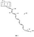
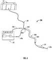
- FIG. 1is an illustration of a system for performing medical/surgical ablation with a plurality of cooling apparatus, according to an embodiment of the present disclosure, disposed on a coaxial cable thereof;
- FIG. 2Ais a perspective view of a hinged cooling apparatus according to an embodiment of the present disclosure
- FIG. 2Bis a transverse cross-sectional view of the hinged cooling apparatus of FIG. 2A ;
- FIG. 3Ais a perspective view of a slip-on cooling apparatus according to an embodiment of the present disclosure.
- FIG. 3Bis a transverse cross-sectional view of the slip-on cooling apparatus of FIG. 3A ;
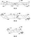
- FIG. 4Ais plan view of cooling apparatus with an elongate body, according to another embodiment of the present disclosure, disposed on a coaxial cable of the surgical ablation system;
- FIG. 4Bis a plan view of the cooling apparatus of FIG. 4A ;
- FIG. 4Cis a plan view of the cooling apparatus of FIG. 4B with an elongate body configured to form a single wrap on a coaxial cable;
- FIG. 5is an illustration of a system for performing medical/surgical ablation including a plurality of cooling apparatus with fluid cooling, according to an embodiment of the present disclosure, disposed on a coaxial cable of the surgical ablation system;
- FIG. 6is a perspective view of the hinged cooling apparatus of FIG. 2A with fluid cooling
- FIG. 7is a perspective view of the slip-on cooling apparatus of FIG. 3A with fluid cooling
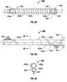
- FIG. 8Ais plan view of a multi-lumen cooling apparatus, according to an embodiment of the present disclosure, disposed on a coaxial cable of the surgical ablation system;
- FIG. 8Bis a plan view of the multi-lumen cooling apparatus of FIG. 8A ;
- FIG. 8Cis a transverse cross-sectional view of the multi-lumen cooling apparatus of FIG. 8B as taken through 8 C- 8 C of FIG. 8B ;
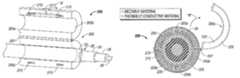
- FIG. 9is a perspective view of a system for performing medical/surgical ablation with a cooling sleeve apparatus, according to yet another embodiment of the present disclosure, disposed on the coaxial cable of the surgical ablation system;
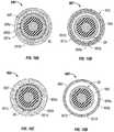
- FIG. 10Ais a transverse cross-sectional view of one embodiment of the cooling sleeve apparatus of FIG. 9 with a cooling body filled with fluid and pressed against the coaxial cable;
- FIG. 10Bis a transverse cross-sectional view of the cooling sleeve apparatus of FIG. 9 with the cooling body empty;
- FIG. 10Cis a transverse cross-sectional view of another embodiment of the cooling sleeve apparatus in FIG. 9 with the cooling body filled with fluid and pressed against the coaxial cable;
- FIG. 10Dis a transverse cross-sectional view of the cooling sleeve apparatus of FIG. 9 with the cooling body empty.
- distalrefers to the portion that is furthest from the user and the term “proximal” refers to the portion that is closest to the user.
- proximalrefers to the portion that is closest to the user.
- terms such as “above”, “below”, “forward”, “rearward”, etc.refer to the orientation of the figures or the direction of components and are simply used for convenience of description.
- Microwave energyis typically delivered to an electrosurgical energy delivery apparatus, such as a microwave antenna assembly, through a coaxial cable.
- an electrosurgical energy delivery apparatussuch as a microwave antenna assembly
- FIG. 1a system for delivering microwave energy, including at least one coaxial cable cooling apparatus 100 according to an embodiment of the present disclosure, is shown as 10 .
- the microwave delivery system 10includes a microwave generator 15 , a coaxial cable 20 operatively connected or coupled to generator 15 , at least one coaxial cable cooling apparatus 100 disposed on coaxial cable 20 , and an electrosurgical energy delivery apparatus 30 including at least one microwave antenna 30 a capable of transmitting microwave energy.
- coaxial cable cooling apparatus 100includes a cooling body or housing 105 configured to attach to at least a portion of the coaxial cable 20 . At least a portion of the housing 105 is configured to absorb thermal energy from at least a portion of the coaxial cable 20 .
- Housing 105may include a cooling portion and a thermal dissipation or thermal energy removal portion.
- Cooling portionmay include a passive cooling means, such as, for example, thermal energy absorbing material with a high thermal mass, energy storage through material phase change, or a thermal energy exchanging means, an active cooling means, such as, for example, fluid cooling, or any suitable combination thereof.
- Thermal dissipation or thermal energy removal portionmay provide a means of removing thermal energy from the coaxial cable 20 and/or cooling apparatus 100 .
- Various passive and active cooling means in accordance with the present disclosureare disclosed hereinbelow.
- microwave delivery system 10may include a plurality of cooling apparatuses 100 spaced from each other and disposed on the coaxial cable 20 . Positioning and spacing between the cooling apparatuses 100 on the coaxial cable 22 may be dependant on a number of factors. Factors include the thermal energy generated by the coaxial cable 20 , the thermal mass of the individual cooling apparatus 100 , the thermal energy absorption rate of the individual cooling apparatus 100 and one or more characteristics of the microwave energy, such as, for example, the frequency, phase and power of the microwave energy.
- the thermal energy generated by the coaxial cable 20may depend upon the medical procedure including the length of time of the procedure, the energy delivered during the procedure, the energy loss characteristics of the cable, the frequency of the energy, the type of tissue targeted by the procedure, and the type of device used for the procedure.
- the number of cooling apparatus 100may depend on the spacing determined by the factors discussed above and the total length of the coaxial cable 20 . In one embodiment, only a single cooling apparatus 100 is utilized.
- the position of the hot spots on the coaxial cable 20may vary and may even move during a procedure thus making placement of the cooling apparatus 100 on an individual hot spot difficult.
- a plurality of cooling apparatus 100may be placed on coaxial cable 20 to provide uniform cooling of the coaxial cable 20 .
- spacing between hot spots on a coaxial cablemay be related to a characteristic of the wavelength, e.g., hot spots may be spaced every half wavelength along the length of the coaxial cable.
- cooling apparatus 100may be spaced uniformly along the coaxial cable 100 with the center of each cooling apparatus spaced one-half wavelength apart. While each individual cooling apparatus 100 may not be positioned directly on a hot spot, the distance from a cooling apparatus 100 to a hot spot, along the coaxial cable 20 , will be uniform.
- a coaxial cable 20includes an outer sheath 22 , an outer conductor 24 , an inner conductor 26 and a dielectric 28 between the outer conductor 24 and the inner conductor 26 .
- Efficient transmission of microwave energy, with minimal amount of microwave energy discharge or loss,requires the inner conductor 26 to be positioned at the approximate radial center of the outer conductor 24 .
- the dielectric 24both positions the inner conductor 26 at the approximate radial center of the outer conductor 24 and insulates the inner conductor 26 and outer conductor 24 by providing a uniform impedance between the inner and outer conductors 26 , 24 .
- a coaxial cable 20to efficiently transmit microwave energy, results in a coaxial cable 20 with excellent transmission properties and typically with very little thermal mass.
- particular amounts of energy discharged within the coaxial cablemay elevate the temperature of the coaxial cable to unacceptable levels. Cable heating is more prevalent with small, flexible cables that are needed when manual manipulation of the cable is required such as, for example, during the placement of a delivery apparatus 30 .
- a cooling apparatus 200in accordance with an embodiment of the present disclosure, is at least partially disposed on coaxial cable 20 .
- Cooling apparatus 200includes a cooling body or housing 205 configured to absorb thermal energy from at least a portion of the coaxial cable 20 .
- Housing 205includes an upper housing portion 205 a and a lower housing portion 205 b inter-connected by a hinge-member 207 (e.g., piano hinge, living hinge, etc.), or other suitable connector.
- Cooling apparatus 200may be reusable or disposable and may be either temporarily or permanently attached to the coaxial cable 20 .
- Cooling apparatus 200may include an attachment means to affix housing 205 to the coaxial cable 20 .
- attachment meansmay include at least one latch 210 extending from the upper housing portion 205 a that enters a corresponding slot 215 formed in the lower housing portion 205 b .
- Attachment meansmay lock the cooling apparatus 200 onto the coaxial cable 20 .
- a latch release 217is provided to slide in the direction of the arrow “A” to release latch 210 from slot 215 .
- Others suitable means of attaching the housing 205 onto the coaxial cablemay be used.
- the cooling apparatus 200includes a thermal mass that is greater than that of the coaxial cable 20 disposed therewithin. Attaching a cooling apparatus 200 such that cooling apparatus 200 is in thermal contact with the coaxial cable 20 increases the overall thermal mass of the body, i.e., the combined thermal mass of the coaxial cable 20 and the cooling apparatus 200 .
- upper housing portion 205 a and/or the lower housing portion 205 bmay draw thermal energy away from, and thereby cool, the coaxial cable 20 .
- increasing the thermal mass of the body, by attaching one or more cooling apparatus 200may decrease the rate at which the cable temperature increases.
- cooling apparatus 200while disposed on and absorbing thermal energy from coaxial cable 20 , may not alter and/or significantly change the physical properties of the coaxial cable 20 , e.g., the spacing and/or positioning of the inner conductor 26 , dielectric layer 28 or outer conductor 24 relative to each other. Additionally, cooling apparatus 200 may not alter and/or significantly change the electrical properties of the coaxial cable 20 , e.g., cable impedance and/or conductive properties thereof.
- an inner surface 205 b of the cooling apparatus 200is configured to contact the sheath 22 of the coaxial cable 20 when cooling apparatus 200 is operatively connected or coupled thereto.
- at least a portion of cooling apparatus 200may pierce the sheath 22 and make direct thermal contact with outer conductor 24 . Direct thermal contact between the cooling apparatus 200 and outer conductor 24 may be desirable to increase the rate of thermal energy removal from the coaxial cable 20 .
- a portion of the sheath 22may be removed to allow direct thermal contact between cooling apparatus 200 and outer conductor 24 .
- FIG. 2Bis a traverse cross-sectional view of the cooling apparatus 200 of FIG. 2A with the upper housing portion 205 a in an open position (shown in phantom) and in a closed position. In a closed position, the upper housing portion 205 a is adjacent the lower housing portion 205 b . As indicated by arrow “B”, the upper housing portion 205 a may pivot relative to the lower housing portion 205 b between a closed position and an open position.
- the coaxial cable 20is placed in the upper or lower housing portion 205 a , 205 b while cooling apparatus 200 is in an open position.
- the upper and lower housing portions 205 a , 205 bare then reposition to a closed position and latch 210 in upper housing portion 205 a connects with slot 215 in lower housing portion 205 b , thereby locking cooling apparatus 200 on coaxial cable 20 .
- Cooling apparatus 200may be removed from coaxial cable 20 by sliding latch release 217 in the direction of arrow “A” (see FIG. 2A ), disengaging latch 210 from slot 215 and repositioning the upper and lower housings 205 a , 205 b to an open position.
- Housing portions 205 a , 205 bmay each define respective cavities 225 for containing material 220 therein, the material 220 having a high thermal mass and/or high energy absorbing properties.
- housing 205may contain a meltable material 220 a , such as wax, disposed within the cavity 225 of housing portions 205 a , 205 b .
- the meltable material 220 amay be solid at room temperature or before cooling apparatus is disposed on the coaxial cable 20 .
- Meltable materialmay be any suitable material that exhibits a phase change while absorbing thermal energy. Phase change may be from a solid to a liquid, from a liquid to vapor or any other suitable phase change that results in the meltable material absorbing thermal energy.
- the melting point or temperature at which the phase change of the meltable material 220 a occursshould be below any unacceptable high temperature for the coaxial cable 20 .
- Various types of waxesmay be suitable because, depending on the specific wax used, the melting point may be between about 40° C. and about 100° C.
- Cavities 225 of housing portions 205 a , 205 bmay be fluid tight thereby sealing the meltable material 220 a therewithin.
- material 220may include a semi-solid or gel. Cooling may occur as the material evaporates from a semi-solid state to vapor or sublimates from solid to a gel.
- Meltable material 220 amay be, solid, soft, pliable or formable prior to the application of the cooling apparatus 100 to coaxial cable 20 to allow housing 205 to conform to coaxial cable 20 .
- the meltable material 220 amay be granulated, microcapsulated or powderized thus allowing an otherwise hard meltable material 220 a to generally conform to the coaxial cable 20 .
- granulating, microcapsulating or powderizing a meltable material 220 amay decrease the individual particle size and increases the overall surface area of the meltable material 220 a and may result in an increase in the rate of thermal energy absorption of material 220 a.
- material 220may include a meltable material 220 a and at least one thermally conductive material 220 b , such as, for example, aluminum or iron.
- the thermally conductive material 220 bmay be homogenously mixed with the meltable material 220 a such that thermally conductive material 220 b distributes the thermal energy throughout the cavities 225 and the meltable material 220 a absorbs the thermal energy.
- the homogenous mixture of a meltable material 220 a and a thermally conductive material 220 bmay result in material 220 with a high thermal mass and a high rate of thermal energy absorption. Addition of the thermally conductive material 220 b may evenly distribute the thermal energy throughout cavity 225 of housing portions 205 a , 205 b.
- thermally conductive materialmay not be homogenously mixed with the meltable material. Instead, thermally conductive material may be positioned within the cavities such that thermal energy is drawn away from the coaxial cable 20 , such as, for example, fins similar to that of a heat exchanger.
- the meltable material 220 amay be a wax selected from a group including insect wax, vegetable wax, mineral wax, animal wax, petroleum wax, synthetic wax and any suitable combination thereof.
- Usable insect waxesinclude but are not limited to beeswax, produced by honey bees, with a melting point between about 61° C.-66° C.; Chinese wax, produced by scale insects such as Coccus ceriferus and Brahmaea japomca (Coccoidea), with a melting point between about 82° C.-84° C.; wax produced by the Icerva purchasi and Dactylopius coccus , with a melting point of about 78° C. and between about 99° C.-101° C., respectively; and Shellac, a wax is secreted by the Lac insect, with a melting point between about 74° C.-78° C.
- Useful vegetable waxesinclude but are not limited to Bayberry wax, from the surface of the berries of the bayberry shrub, with a melting point of about 45° C.; Candelilla wax, from the Mexican shrubs Euphorbia cerifera and E. antisyphilitica , with a melting point between about 67° C.-79° C.; Carnauba wax, from the leaves of the Carnauba palm, with a melting point between about 78° C.-85° C.; Castor wax, formed from hydrogenated castor oil, with a melting point between about 61° C.-69° C.; Japan wax, formed from a byproduct of lacquer manufacture, with a melting point of about 53° C.; Ouricury wax, from the Brazilian Feather palm, with a melting point between about 81° C. and 84° C.; and Rice bran wax, obtained from rice bran, with a melting point between about 77° C.-86° C.
- Usable mineral waxesinclude but are not limited to Montan wax, extracted from lignite and brown coal, with a melting point between about 82° C.-95° C.; and Ozocerite, a naturally occurring wax found in lignite beds, with a melting point between about 58° C.-100° C.
- Usable animal waxesinclude but are not limited to Spermacet, obtained from the head cavities and blubber of the sperm whales and Lanolin, also known as wool wax, obtained from the sebaceous glands of sheep with a melting point between about 35° C.-42° C.
- Usable petroleum waxesinclude but are not limited to Paraffin wax, made of long-chain alkane hydrocarbons, with a melting point between about 47° C.-64° C.; and Microcrystalline wax, produced by de-oiling petrolatum, with a melting point between about 60° C.-80° C.
- Usable synthetic waxesincluding but are not limited to polyethylene waxes, based on polyethylene, and waxes chemically modified such as, for example, esterified or saponified, substituted amide waxes and polymerized ⁇ -olefins.
- Material 220may include any suitable material, or mixture of materials, capable of absorbing and retaining a thermal load.
- Cooling apparatus 300includes a cooling body or housing 305 forming a lumen 330 in the approximate radial center of the cooling housing 305 . Access to the lumen 330 is provided by a channel 335 extending through housing 305 and extending an entire length thereof. Housing 305 is sufficiently flexible such that housing 205 can be manipulated to open or expand channel 335 , in the direction of the opposing arrows “C”, to allow coaxial cable 20 to slip through channel 335 and into lumen 330 .
- a flap 340fastened to housing 305 on one side of channel 335 , may be used to close the channel 335 by selectively attaching to housing 305 at a flap attachment area 340 a on the second side of channel 335 .
- Flap attachment area 340 amay use any suitable attachment means, such as, for example, hook and loop type fasteners, adhesive, tape, snaps, buttons or latches.
- channel 335is opened by pulling the housing 305 in the direction of the opposing arrows “C” and the coaxial cable 20 is removed from lumen 330 .
- the diameter of lumen 330is sized to be substantially equal to an outer diameter of the coaxial cable 20 such that when the channel 335 is closed, with the coaxial cable 20 in the lumen 330 , the housing 305 makes substantial contact with a length of the coaxial cable 20 .
- housing 305forms a chamber 325 that contains thermal energy absorbing material 320 as discussed hereinabove. Material may be contained within chamber 325 by a fluid-tight manner.
- an internal surface of the housing 305 within the lumen 330may pierce the sheath 22 and make thermal contact with the outer conductor 24 to facilitate the removal of thermal energy from the coaxial cable 20 .
- Cooling apparatus 400includes an elongate cooling body 405 in the form of a tape-like structure for wrapping coaxial cable 20 . Cooling apparatus 400 may be wrapped along or around coaxial cable 20 , as illustrated in FIG. 4A . Cooling apparatus 400 includes a flap 440 on each end of cooling body 405 that attaches to a flap landing area 440 a and secures cooling apparatus 400 to the coaxial cable 20 . Housing 405 contains thermal energy absorbing material as discussed in the embodiments above.
- the length of coaxial cable 20 covered by the cooling apparatus 400is determined by the width of the cooling body 405 , the pitch or angle of the wrap, the amount of overlap between two adjacent wraps, the diameter of the coaxial cable 20 and the length of the cooling apparatus 400 .
- FIGS. 4A and 4Billustrate a cooling apparatus 400 wrapped approximately four times around a coaxial cable 20 , with little or no overlap between wraps, at a pitch of approximately 45 degrees.
- the length of coaxial cable 20 covered by the cooling apparatus 400may be approximately four times the width of the cooling body 405 .
- FIG. 4Billustrates an extended or unwrapped cooling apparatus 400 of FIG. 4A .
- the length and widthmay be larger or smaller based on the dimensions of coaxial cable covered by the cooling apparatus 400 .
- Increasing the length of cooling apparatus 400may increase the number of times the cooling apparatus 400 will wrap around the coaxial cable 20 .
- Increasing the width of cooling apparatus 400may increase the amount of coaxial cable 20 covered by each wrap.
- each flap 440 and the size and position of each flap attachment area 440 a on the cooling apparatus 400may be adjusted for different coaxial cable 20 dimensions.
- the center of the flap 440 and the center of the flap attachment area 440 aare spaced such that when the cooling apparatus 400 is wrapped around the coaxial cable 20 the flap 440 folds onto at least a portion of the flap attachment area 440 a .
- the spacing between the flap 440 and the flap attachment area 440 ais about equal to, or greater than, the circumference of the coaxial cable 20 . Spacing between the flap 440 and the flap attachment area 440 a may be adjusted for larger diameter or smaller diameter coaxial cables.
- a cooling apparatus 401is provided and includes a single-wrap around a portion of the coaxial cable. Cooling apparatus 401 may be applied to specific hot-spots in or along the transmission path, such as, for example, connections to the coaxial cable, connections between two coaxial cables and bends or kinks in a coaxial cable.
- the cooling apparatus 100 , 200 , 300 , 400 and 401 with passive cooling discussed hereinaboveare attached to a coaxial cable 20 thereby increasing the thermal mass of the body.
- the meltable materialcontained therewithin, absorbs energy and may change from a solid state to a melted state.
- meltable materialmay cool to a temperature below the melting point of the meltable material and may re-solidify to a solid state.
- a cooling apparatusmay absorbed an amount of thermal energy such that material in the cooling apparatus melts and coaxial cable and/or cooling apparatus may approach an unacceptable temperature.
- Clinicianmay replace the heated cooling apparatus, containing the melted material, with an unheated cooling apparatus, thereby providing additional passive cooling for the coaxial cable.
- cooling apparatuscools and meltable material re-solidifies to a solid-like state.
- cooling apparatus 400may contain a temperature sensor 470 to sense the temperature of the cooling apparatus 400 .
- Temperature sensor 470may include an indicator 470 a , such as, for example, a strip-type indicator or other suitable display, to provide the temperature of the cooling apparatus 400 to a clinician.
- sensormay include an electronic circuit (not explicitly shown) to measure and indicate a temperature.
- Electronic circuit(not explicitly shown) may include a means to communicate a temperature to a remote system, such as, for example, a computer or other suitable information collection system.
- a system for delivering microwave energyincluding at least one cooling apparatus 500 according to an embodiment of the present disclosure, for actively cooling a coaxial cable 20 is shown as 10 a .
- the microwave delivery system 10 aincludes a microwave generator 15 , a coaxial cable 20 with at least one coaxial cable cooling apparatus 500 disposed on the coaxial cable 20 , a system 40 for supplying cooling fluid and an electrosurgical energy delivery apparatus 30 , including at least one microwave antenna 30 a capable of transmitting microwave energy.
- Coaxial cable cooling apparatus 500(hereinafter “cooling apparatus 500 ”) includes a cooling body or housing 505 configured to attached to at least a portion of the coaxial cable 20 , at least one inlet member 545 , and at least one outlet member 547 .
- the one or more inlet members 545 and one or more outlet members 547may be disposed in, formed by, or defined by housing 505 .
- Cooling fluidis supplied to the at least one inlet member 545 by cooling fluid supply 40 and circulated through at least a portion of the housing 505 .
- the fluid circulated therethroughabsorbs thermal energy generated by the coaxial cable 20 from the cooling apparatus 500 , or any portion therewithin. Alternatively, the fluid circulating therethrough may absorb thermal energy directly from the coaxial cable 20 .
- Fluidis discharged from the housing 505 through the at least one outlet member 547 .
- FIG. 6illustrates a cooling apparatus 500 , similar to cooling apparatus 200 of FIG. 2A , with a plurality of inlets 545 a - 545 d disposed in the lower housing 505 b .
- Fluidis delivered to at least one of the inlets 545 a - 545 d and circulated through the lower housing 505 b .
- a jumper hose 549fluidly inter-connects to upper housing 505 a and lower housing 505 b to circulate fluid between the upper housing 505 a and the lower housing 505 b .
- Fluidis discharged from the cooling apparatus 500 through at least one of the plurality of the outlets 547 a - 547 b disposed in the upper housing 505 a .
- Fluid circulated through housing 505may absorb thermal energy from at least one of the lower housing 505 a , the upper housings 505 b and the material contained therewithin.
- Materialmay include a material with a high thermal mass and high energy absorbing properties as discussed herein.
- cooling fluid supply 40may include a pump 41 for circulating the fluid, a cooling unit 42 for cooling the fluid returned from the cooling apparatus 500 through the return manifold 43 .
- Fluidmay be a thermally conductive fluid, such as, for example, water, saline, ammonium chloride, sodium nitrate, potassium chloride or any suitable fluid selected for the intended purpose of dissipating heat.
- FIG. 7illustrates yet another embodiment of a cooling apparatus 700 of the present disclosure.
- Cooling apparatus 700includes a cooling body or housing 705 , defining an inner lumen 730 and a channel 735 , and an inlet 745 and an outlet 747 formed in the housing 705 .
- Flap 740connects to the housing 705 on one side of the channel 735 and attaches to flap attachment area 740 a on housing 705 on the opposite side of channel 735 .
- Cooling fluidis supplied to inlet 745 of housing 705 , circulated through housing 705 before being discharged through outlet 747 . Cooling fluid may be circulated through a portion of the housing 705 adjacent to and in thermal communication with the coaxial cable 20 to absorb thermal energy therefrom.
- Cooling apparatus 800includes a cooling body, or housing 805 , having at least two tubes 850 a , 850 b , one or more attachment flaps 840 , and defining one or more flap attachment areas 840 a .
- An inlet member 845 and an outlet member 847may be fluidly connected to, or are integrally formed with, cooling tube 850 a and return tube 850 b , respectively. Fluid is supplied to inlet member 845 and is circulated though cooling tube 850 a and return tube 850 b . Thermal energy from the coaxial cable 20 and/or the cooling apparatus 800 is absorbed by the cooling fluid and is discharged through return tube 850 b.
- cooling apparatus 800is disposed on a coaxial cable 20 . Cooling apparatus 800 is wrapped around the coaxial cable 20 . Cooling apparatus 800 is secured on each end by flaps 840 that selectively attach to flap attachment areas 840 a.
- the absorption rate of thermal energy from the coaxial cable 20 by cooling apparatus 800is dependant on several factors.
- One factoris the contact surface area between the cooling and return tubes 850 a , 850 b and coaxial cable 20 .
- the contact surface area between the cooling and return tubes 850 a , 850 bmay be increased by forming cooling and return tubes 850 a , 850 b from flexible and/or malleable material such that when disposed on coaxial cable 20 the cooling and return tubes 850 a , 850 b conform to the surface of the coaxial cable 20 .
- Cooling and return tubes 850 a , 850 bmay be formed from any suitable tubing such as, for example, medical tubing and paratubes.
- cooling tube 850 amay be formed from a suitable material that conforms to the coaxial cable 20 and the return tube 850 b , which carries fluid already heated in the cooling tube 850 a , may be formed from a suitable material that does not conform to the coaxial cable.
- the cooling tube 850 acontacts the coaxial cable 20 and the return tube 850 b is spaced away from the coaxial cable 20 , thereby not making contact with the coaxial cable 20 .
- the at least one or more tubes 850 a , 850 bmay be formed from multi-lumen tubing made from various materials such as, for example, polytetrafluoroethylene (PTFE), such as the material sold under the trademark TeflonTM and available from DuPont, perfluoroalkoxy (PFA), polytetrafluoroethylene (FEP) or expanded PTFE (ePTFE).
- PTFEpolytetrafluoroethylene
- TeflonTMperfluoroalkoxy
- FEPpolytetrafluoroethylene
- ePTFEexpanded PTFE
- FIG. 8Cis a transverse cross-sectional view of the cooling apparatus 800 of FIG. 8B formed from a multi-lumen tube 850 .
- Multi-lumen tube 850forms a cooling tube 850 a and a return tube 850 b with at least one common wall shared therebetween.
- a system for delivering microwave energyincluding at least one coaxial cable cooling sleeve apparatus 900 , according to an embodiment of the present disclosure, for actively cooling a coaxial cable 20 is shown as 10 b .
- the microwave delivery system 12includes a microwave generator 15 , a coaxial cable 20 with at least one coaxial cable cooling sleeve apparatus 900 disposed on the coaxial cable 20 , a system 40 for supplying cooling fluid and an electrosurgical energy delivery apparatus 30 , including at least one microwave antenna 30 a , capable of transmitting microwave energy.
- Coaxial cable cooling sleeve apparatus 900(hereinafter “cooling sleeve apparatus”) includes a cooling body 905 , configure to surround at least a portion of coaxial cable 20 , at least one inlet 945 , and at least one outlet 947 .
- Cooling fluidis supplied to the at least one inlet 945 by cooling fluid supply 40 via a conduit 40 a and circulated through at least a portion of the cooling body 905 .
- Fluid circulated through cooling body 905absorbs thermal energy generated by the coaxial cable 20 and/or from the cooling apparatus 900 , and/or any portion therewithin.
- the heated fluidis discharged through the outlet 947 via conduit 40 b.
- FIGS. 10A-10B and FIGS. 10C-10Dtransverse cross-section views of two embodiments of the cooling sleeve apparatus 900 of FIG. 9 are illustrated.
- the housing 905 of a cooling sleeve apparatus 901forms inner and outer concentric portions 951 a , 951 b , respectively, each forming at least one fluid tight chamber therewithin.
- the housing 905 of a cooling sleeve apparatus 902forms a cooling portion 951 c and a return portion 951 d , each defining a fluid-tight chamber therewithin.
- FIGS. 10A-10B and FIGS. 10C-10Dtransverse cross-section views of two embodiments of the cooling sleeve apparatus 900 of FIG. 9 are illustrated.
- the housing 905 of a cooling sleeve apparatus 901forms inner and outer concentric portions 951 a , 951 b , respectively, each forming at least one fluid tight chamber therewithin.
- the fluid-tight chambersare filled with fluid thereby pressing the inner surface 905 b of the housing 905 into the coaxial cable 20 .
- Inner surface 905 bmay be flexible and/or stretchable such that inner surface 905 b of the housing 905 and the outer surface 905 a of the coaxial cable 20 form suitable thermally conductive contact with one another.
- the inlet 945connects to the inner concentric portion 951 a of the cooling apparatus 901 in FIGS. 10A and 10B , or to the cooling portion 951 c of the cooling apparatus 902 in FIGS. 10C and 10D , and supplies cooling fluid thereto.
- the outlet 947connects to the outer concentric portion 951 b of the cooling apparatus 901 in FIGS. 10A and 10B , or to the return portion 951 d of the cooling apparatus 902 in FIGS. 10C and 10D .
- fluidpasses from the inner concentric portion 951 a to the outer concentric portion 951 b , or from the cooling portion 951 c to the return portion 951 d , through openings therebetween (not explicitly shown). Fluid then flows proximally through the outer concentric portion 951 b or the return portion 951 d and is discharged through the outlet 947 .
- the fluid-tight chambersare not fluid-filled thereby defining a space or cavity 960 between the inner surface 905 b of the housing 905 and the coaxial cable 20 .
- the shape of the cooling sleeve apparatus 901 , 902may be defined by a rigid or semi-rigid outer surface 905 a of housing 905 . The shape may be maintained by the outer surface 905 a after a majority of the fluid is removed. Removal of fluid from the housing 905 may create a vacuum therewithin and may pull the inner surface 905 b of the housing 905 toward the outer surface 905 a thereby increasing the size or volume of space or cavity 960 between the inner surface 905 b of the housing 905 and the coaxial cable 20 .
- Space 960may be sufficiently large to allow the coaxial cable 20 to be threaded or inserted through space 960 thus providing a means of attaching the cooling apparatus 901 , 902 to the coaxial cable 20 .
- the present applicationdiscloses apparatus and methods for cooling coaxial cables. It is envisioned that the various embodiments described hereinabove may be combined. For example, elements of the passive cooling apparatus may be applied to the various active cooling apparatus. While the embodiments contained herewithin are described in the context of cooling coaxial cables transmitting microwave energy any apparatus or method may be used to cool any cable, wire or elongated member. Modification of the above-described apparatuses and methods, and variations of aspects of the disclosure that are obvious to those of skill in the art are intended to be within the scope of the claims.
Landscapes
- Engineering & Computer Science (AREA)
- Physics & Mathematics (AREA)
- Chemical & Material Sciences (AREA)
- Thermal Sciences (AREA)
- Mechanical Engineering (AREA)
- General Engineering & Computer Science (AREA)
- Chemical Kinetics & Catalysis (AREA)
- Combustion & Propulsion (AREA)
- Materials Engineering (AREA)
- Organic Chemistry (AREA)
- Surgical Instruments (AREA)
Abstract
Description
Claims (15)
Priority Applications (2)
| Application Number | Priority Date | Filing Date | Title |
|---|---|---|---|
| US11/820,193US7777130B2 (en) | 2007-06-18 | 2007-06-18 | Microwave cable cooling |
| US12/814,787US8093500B2 (en) | 2007-06-18 | 2010-06-14 | Microwave cable cooling |
Applications Claiming Priority (1)
| Application Number | Priority Date | Filing Date | Title |
|---|---|---|---|
| US11/820,193US7777130B2 (en) | 2007-06-18 | 2007-06-18 | Microwave cable cooling |
Related Child Applications (1)
| Application Number | Title | Priority Date | Filing Date |
|---|---|---|---|
| US12/814,787DivisionUS8093500B2 (en) | 2007-06-18 | 2010-06-14 | Microwave cable cooling |
Publications (2)
| Publication Number | Publication Date |
|---|---|
| US20080308256A1 US20080308256A1 (en) | 2008-12-18 |
| US7777130B2true US7777130B2 (en) | 2010-08-17 |
Family
ID=40131241
Family Applications (2)
| Application Number | Title | Priority Date | Filing Date |
|---|---|---|---|
| US11/820,193Expired - Fee RelatedUS7777130B2 (en) | 2007-06-18 | 2007-06-18 | Microwave cable cooling |
| US12/814,787Expired - Fee RelatedUS8093500B2 (en) | 2007-06-18 | 2010-06-14 | Microwave cable cooling |
Family Applications After (1)
| Application Number | Title | Priority Date | Filing Date |
|---|---|---|---|
| US12/814,787Expired - Fee RelatedUS8093500B2 (en) | 2007-06-18 | 2010-06-14 | Microwave cable cooling |
Country Status (1)
| Country | Link |
|---|---|
| US (2) | US7777130B2 (en) |
Cited By (8)
| Publication number | Priority date | Publication date | Assignee | Title |
|---|---|---|---|---|
| US20110295246A1 (en)* | 2010-05-26 | 2011-12-01 | Vivant Medical, Inc. | System and Method for Chemically Cooling an Ablation Antenna |
| US20120215214A1 (en)* | 2007-09-07 | 2012-08-23 | Tyco Healthcare Group Lp | Cool Tip Junction |
| US8845627B2 (en) | 2008-08-22 | 2014-09-30 | Boston Scientific Scimed, Inc. | Regulating pressure to lower temperature in a cryotherapy balloon catheter |
| US8932281B2 (en) | 2011-01-05 | 2015-01-13 | Covidien Lp | Energy-delivery devices with flexible fluid-cooled shaft, inflow/outflow junctions suitable for use with same, and systems including same |
| US9011421B2 (en) | 2011-01-05 | 2015-04-21 | Covidien Lp | Energy-delivery devices with flexible fluid-cooled shaft, inflow/outflow junctions suitable for use with same, and systems including same |
| US9017319B2 (en) | 2011-01-05 | 2015-04-28 | Covidien Lp | Energy-delivery devices with flexible fluid-cooled shaft, inflow/outflow junctions suitable for use with same, and systems including same |
| US9770294B2 (en) | 2011-01-05 | 2017-09-26 | Covidien Lp | Energy-delivery devices with flexible fluid-cooled shaft, inflow/outflow junctions suitable for use with same, and systems including same |
| CN112710935A (en)* | 2021-03-29 | 2021-04-27 | 华东交通大学 | Power wire and cable protective layer ablation condition pre-alarming system and method |
Families Citing this family (28)
| Publication number | Priority date | Publication date | Assignee | Title |
|---|---|---|---|---|
| US10363092B2 (en) | 2006-03-24 | 2019-07-30 | Neuwave Medical, Inc. | Transmission line with heat transfer ability |
| US11389235B2 (en) | 2006-07-14 | 2022-07-19 | Neuwave Medical, Inc. | Energy delivery systems and uses thereof |
| US10376314B2 (en) | 2006-07-14 | 2019-08-13 | Neuwave Medical, Inc. | Energy delivery systems and uses thereof |
| US7777130B2 (en)* | 2007-06-18 | 2010-08-17 | Vivant Medical, Inc. | Microwave cable cooling |
| US8945111B2 (en) | 2008-01-23 | 2015-02-03 | Covidien Lp | Choked dielectric loaded tip dipole microwave antenna |
| US9949794B2 (en) | 2008-03-27 | 2018-04-24 | Covidien Lp | Microwave ablation devices including expandable antennas and methods of use |
| US20100045559A1 (en)* | 2008-08-25 | 2010-02-25 | Vivant Medical, Inc. | Dual-Band Dipole Microwave Ablation Antenna |
| US9173706B2 (en)* | 2008-08-25 | 2015-11-03 | Covidien Lp | Dual-band dipole microwave ablation antenna |
| US8251987B2 (en) | 2008-08-28 | 2012-08-28 | Vivant Medical, Inc. | Microwave antenna |
| US8118808B2 (en)* | 2009-03-10 | 2012-02-21 | Vivant Medical, Inc. | Cooled dielectrically buffered microwave dipole antenna |
| EP3549544B1 (en) | 2009-07-28 | 2021-01-06 | Neuwave Medical, Inc. | DEVICE FOR ABLATION |
| US8343145B2 (en)* | 2009-09-28 | 2013-01-01 | Vivant Medical, Inc. | Microwave surface ablation using conical probe |
| ES2856026T3 (en) | 2010-05-03 | 2021-09-27 | Neuwave Medical Inc | Power supply systems |
| US9192438B2 (en) | 2011-12-21 | 2015-11-24 | Neuwave Medical, Inc. | Energy delivery systems and uses thereof |
| US9119648B2 (en) | 2012-01-06 | 2015-09-01 | Covidien Lp | System and method for treating tissue using an expandable antenna |
| US9113931B2 (en) | 2012-01-06 | 2015-08-25 | Covidien Lp | System and method for treating tissue using an expandable antenna |
| WO2016210001A1 (en)* | 2015-06-22 | 2016-12-29 | Pyrexar Medical Inc. | Hyperthermia electromagnetic energy applicator housing and hyperthermia patient support system |
| CN108139015B (en)* | 2015-08-20 | 2020-05-12 | 哈金森公司 | Assembly with intermediate positioning portion for thermal insulation and hinged panel |
| CN113367788B (en) | 2015-10-26 | 2024-09-06 | 纽韦弗医疗设备公司 | Energy delivery systems and uses thereof |
| US10531917B2 (en) | 2016-04-15 | 2020-01-14 | Neuwave Medical, Inc. | Systems and methods for energy delivery |
| WO2017197114A1 (en) | 2016-05-11 | 2017-11-16 | Affera, Inc. | Anatomical model generation |
| WO2017197294A1 (en) | 2016-05-12 | 2017-11-16 | Affera, Inc. | Three-dimensional cardiac representation |
| DE102016109550A1 (en)* | 2016-05-24 | 2017-11-30 | Yazaki Systems Technologies Gmbh | Wiring harness and arrangement with such a wiring harness |
| US11672596B2 (en) | 2018-02-26 | 2023-06-13 | Neuwave Medical, Inc. | Energy delivery devices with flexible and adjustable tips |
| DE102018120932B4 (en)* | 2018-08-28 | 2021-02-18 | Volkswagen Aktiengesellschaft | Cable section, system and method for power transmission within a motor vehicle and a motor vehicle, having a cable section |
| US12268456B2 (en) | 2019-01-23 | 2025-04-08 | Affera, Inc. | Systems and methods for therapy annotation |
| US11832879B2 (en) | 2019-03-08 | 2023-12-05 | Neuwave Medical, Inc. | Systems and methods for energy delivery |
| WO2021026470A1 (en)* | 2019-08-07 | 2021-02-11 | Biocompatibles Uk Limited | Cooling system for surgical device |
Citations (65)
| Publication number | Priority date | Publication date | Assignee | Title |
|---|---|---|---|---|
| US2029420A (en) | 1929-05-23 | 1936-02-04 | American Telephone & Telegraph | Concentric conductor transmission system |
| US2165961A (en) | 1935-10-22 | 1939-07-11 | Emi Ltd | High frequency signaling system |
| US2510358A (en) | 1946-03-20 | 1950-06-06 | Rca Corp | Art of making concentric transmission lines |
| US3060210A (en)* | 1960-05-12 | 1962-10-23 | Petrolite Corp | Polyaminomethyl phenols |
| US3634606A (en) | 1970-06-15 | 1972-01-11 | Northern Electric Co | Outer conductor for coaxial cable |
| US3777371A (en) | 1972-02-16 | 1973-12-11 | Northern Electric Co | Method of controlling the characteristics impedance of coaxial cables |
| US3885083A (en) | 1969-09-29 | 1975-05-20 | Gen Cable Corp | Pressure fused watertight disc coaxial cable |
| US3893355A (en) | 1973-12-21 | 1975-07-08 | Giddings & Lewis | Coolant supply system for cutting tools in a machine tool |
| US3943470A (en) | 1973-08-06 | 1976-03-09 | Sealectro Corporation | Right angle connector |
| US4092485A (en) | 1975-11-03 | 1978-05-30 | Gould, Inc. | Gas insulated electrical high or very high voltage cable |
| US4143649A (en) | 1977-01-24 | 1979-03-13 | George Foti | Pump for closed circulation system |
| US4198828A (en) | 1977-06-09 | 1980-04-22 | Societe d'Etudes d'Automatisation, de Regulation et d'Appareils de Mesures S.A. | Cryostat and coolant-supply system therefore |
| US4377547A (en)* | 1982-01-18 | 1983-03-22 | Minnesota Mining And Manufacturing Company | Molded high voltage splice body |
| US4415763A (en) | 1980-11-14 | 1983-11-15 | Westinghouse Electric Corp. | Gas-insulated transmission line having improved outer enclosure |
| US4493710A (en) | 1983-11-14 | 1985-01-15 | Ivy Medical, Inc. | Intravenous drip rate control device |
| US4648919A (en)* | 1984-09-18 | 1987-03-10 | Raychem Corp. | Protection of cable splice |
| US4865123A (en) | 1987-10-22 | 1989-09-12 | Fujitsu Limited | Apparatus for supplying cooling fluid |
| US5048598A (en) | 1989-02-06 | 1991-09-17 | Fujitsu Limited | Reservior tank for a liquid cooling system |
| US5147161A (en) | 1991-10-28 | 1992-09-15 | Whiting Robert L | Retrofit coolant supply system for a machine tool |
| US5190421A (en) | 1991-11-20 | 1993-03-02 | Hardinge Brothers, Inc. | Coolant supply system for a machine tool |
| US5312658A (en)* | 1991-05-07 | 1994-05-17 | Progressive Polymerics Inc. | Conduits having a shock absorbing shell and method for their formation |
| US5334193A (en) | 1992-11-13 | 1994-08-02 | American Cardiac Ablation Co., Inc. | Fluid cooled ablation catheter |
| US5348554A (en) | 1992-12-01 | 1994-09-20 | Cardiac Pathways Corporation | Catheter for RF ablation with cooled electrode |
| US5358515A (en) | 1989-08-16 | 1994-10-25 | Deutsches Krebsforschungzentrum Stiftung Des Offentlichen Rechts | Microwave hyperthermia applicator |
| US5535818A (en) | 1992-10-12 | 1996-07-16 | Fujitsu Limited | Cooling system for electronic device |
| US5620440A (en) | 1993-11-13 | 1997-04-15 | Richard Wolf Gmbh | Medical instrument for applying hot gas |
| US5703536A (en) | 1996-04-08 | 1997-12-30 | Harris Corporation | Liquid cooling system for high power solid state AM transmitter |
| US5843021A (en) | 1994-05-09 | 1998-12-01 | Somnus Medical Technologies, Inc. | Cell necrosis apparatus |
| US5951546A (en) | 1994-12-13 | 1999-09-14 | Lorentzen; Torben | Electrosurgical instrument for tissue ablation, an apparatus, and a method for providing a lesion in damaged and diseased tissue from a mammal |
| US5951216A (en) | 1997-09-19 | 1999-09-14 | Antoun; Gregory S. | Programmable, variable volume and pressure, coolant system |
| US6007571A (en) | 1996-04-25 | 1999-12-28 | Urologix, Inc. | Liquid coolant supply system |
| US6106504A (en) | 1998-07-15 | 2000-08-22 | Urrutia; Hector | Drip chamber for medical fluid delivery system |
| US6112813A (en)* | 1997-02-20 | 2000-09-05 | Head; Philip | Method of providing a conduit and continuous coiled tubing system |
| US6134476A (en) | 1996-04-17 | 2000-10-17 | The United States Of America As Represented By The Administrator Of The National Aeronautics And Space Administration | Transcatheter antenna for microwave treatment |
| US6149677A (en) | 1998-03-31 | 2000-11-21 | Innercool Therapies, Inc. | Circulating fluid hypothermia method |
| US6259074B1 (en) | 1999-10-26 | 2001-07-10 | Sims Level 1, Inc. | Apparatus for regulating the temperature of a fluid |
| US6259067B1 (en) | 1998-10-16 | 2001-07-10 | Medical Solutions, Inc. | Temperature control system and method for heating and maintaining medical items at desired temperatures |
| US6348049B1 (en) | 1994-03-30 | 2002-02-19 | Denco, Inc. | Surgical/medical tubing and containers for use in conveying medical solutions and the like |
| US20020026187A1 (en) | 2000-08-30 | 2002-02-28 | Scimed Life Systems, Inc. | Fluid cooled apparatus for supporting diagnostic and therapeutic elements in contact with tissue |
| US6355024B1 (en) | 1999-07-14 | 2002-03-12 | Mallinckrodt Inc. | Medical fluid delivery system |
| US6371157B1 (en) | 2000-09-29 | 2002-04-16 | Thales Broadcast & Multimedia, Inc. | Method, system and computer program product for self-draining plumbing for liquid-cooled devices |
| US6383180B1 (en) | 1999-01-25 | 2002-05-07 | Cryocath Technologies Inc. | Closed loop catheter coolant system |
| USRE37704E1 (en) | 1990-03-22 | 2002-05-14 | Argomed Ltd. | Thermal treatment apparatus |
| US20020111615A1 (en) | 1993-12-15 | 2002-08-15 | Eric R. Cosman | Cluster ablation electrode system |
| US6468258B1 (en) | 1997-07-18 | 2002-10-22 | Baxter International Inc. | Plastic compositions including vitamin E for medical containers and methods for providing such compositions and containers |
| US6506189B1 (en) | 1995-05-04 | 2003-01-14 | Sherwood Services Ag | Cool-tip electrode thermosurgery system |
| US6524308B1 (en) | 1997-09-04 | 2003-02-25 | Celon Ag Medical Instruments | Electrode arrangement for electrothermal treatment of human or animal bodies |
| US20030040743A1 (en) | 1999-06-11 | 2003-02-27 | Cosman Eric R. | Ablation treatment of bone metastases |
| US6577903B1 (en) | 1998-05-06 | 2003-06-10 | Microsulis Plc | Thermal sensor positioning in a microwave waveguide |
| US6575969B1 (en) | 1995-05-04 | 2003-06-10 | Sherwood Services Ag | Cool-tip radiofrequency thermosurgery electrode system for tumor ablation |
| US6592577B2 (en) | 1999-01-25 | 2003-07-15 | Cryocath Technologies Inc. | Cooling system |
| US6635053B1 (en) | 1999-01-25 | 2003-10-21 | Cryocath Technologies Inc. | Cooling system |
| US20030216733A1 (en) | 2002-05-16 | 2003-11-20 | Mcclurken Michael E. | Fluid-assisted medical devices, systems and methods |
| US6706040B2 (en) | 2001-11-23 | 2004-03-16 | Medlennium Technologies, Inc. | Invasive therapeutic probe |
| US6723094B1 (en) | 1998-12-18 | 2004-04-20 | Kai Desinger | Electrode assembly for a surgical instrument provided for carrying out an electrothermal coagulation of tissue |
| US20040087941A1 (en) | 1998-05-20 | 2004-05-06 | Wang Paul J. | Cardiac system and method for treatment of cardiac arrhythmias and transmyocardial revascularization |
| US20040111086A1 (en) | 2002-12-09 | 2004-06-10 | Trembly B. Stuart | Feedback control of thermokeratoplasty treatments |
| US20050015081A1 (en) | 2003-07-18 | 2005-01-20 | Roman Turovskiy | Devices and methods for cooling microwave antennas |
| US6847848B2 (en) | 2003-01-07 | 2005-01-25 | Mmtc, Inc | Inflatable balloon catheter structural designs and methods for treating diseased tissue of a patient |
| US6849063B1 (en) | 1994-03-11 | 2005-02-01 | Wit Ip Corporation | Thermal treatment apparatus |
| US20050065584A1 (en) | 2003-09-09 | 2005-03-24 | Schiff Jonathan D. | System and method for cooling internal tissue |
| US6893419B2 (en) | 1998-04-21 | 2005-05-17 | Alsius Corp. | Indwelling heat exchange catheter and method of using same |
| US6956164B2 (en) | 2003-12-23 | 2005-10-18 | Spx Corporation | Inner conductor supports for rigid coaxial transmission lines |
| US20050245920A1 (en) | 2004-04-30 | 2005-11-03 | Vitullo Jeffrey M | Cell necrosis apparatus with cooled microwave antenna |
| US20060243471A1 (en)* | 2005-01-31 | 2006-11-02 | Karlsen Jan E | Protection profile for subsea cables |
Family Cites Families (94)
| Publication number | Priority date | Publication date | Assignee | Title |
|---|---|---|---|---|
| DE390937C (en) | 1922-10-13 | 1924-03-03 | Adolf Erb | Device for internal heating of furnace furnaces for hardening, tempering, annealing, quenching and melting |
| DE1099658B (en) | 1959-04-29 | 1961-02-16 | Siemens Reiniger Werke Ag | Automatic switch-on device for high-frequency surgical devices |
| FR1275415A (en) | 1960-09-26 | 1961-11-10 | Device for detecting disturbances for electrical installations, in particular electrosurgery | |
| DE1139927B (en) | 1961-01-03 | 1962-11-22 | Friedrich Laber | High-frequency surgical device |
| DE1149832C2 (en) | 1961-02-25 | 1977-10-13 | Siemens AG, 1000 Berlin und 8000 München | HIGH FREQUENCY SURGICAL EQUIPMENT |
| FR1347865A (en) | 1962-11-22 | 1964-01-04 | Improvements to diathermo-coagulation devices | |
| DE1439302B2 (en) | 1963-10-26 | 1971-05-19 | Siemens AG, 1000 Berlin u 8000 München | High frequency surgical device |
| SU401367A1 (en) | 1971-10-05 | 1973-10-12 | Тернопольский государственный медицинский институт | BIAKTIVNYE ELECTRO SURGICAL INSTRUMENT |
| FR2235669A1 (en) | 1973-07-07 | 1975-01-31 | Lunacek Boris | Gynaecological sterilisation instrument - has hollow electrode protruding from the end of a curved ended tube |
| GB1480736A (en) | 1973-08-23 | 1977-07-20 | Matburn Ltd | Electrodiathermy apparatus |
| FR2251864A1 (en) | 1973-11-21 | 1975-06-13 | Termiflex Corp | Portable input and output unit for connection to a data processor - is basically a calculator with transmitter and receiver |
| DE2407559C3 (en) | 1974-02-16 | 1982-01-21 | Dornier System Gmbh, 7990 Friedrichshafen | Heat probe |
| DE2415263A1 (en) | 1974-03-29 | 1975-10-02 | Aesculap Werke Ag | Surgical H.F. coagulation probe has electrode tongs - with exposed ends of insulated conductors forming tong-jaws |
| DE2429021C2 (en) | 1974-06-18 | 1983-12-08 | Erbe Elektromedizin GmbH, 7400 Tübingen | Remote switching device for an HF surgical device |
| FR2276027A1 (en) | 1974-06-25 | 1976-01-23 | Medical Plastics Inc | Plate electrode with connector - is clamped between connector jaws held by releasable locking device |
| DE2460481A1 (en) | 1974-12-20 | 1976-06-24 | Delma Elektro Med App | Electrode grip for remote HF surgical instrument switching - has shaped insulated piece with contact ring of sterilizable (silicon) rubber |
| US4237887A (en) | 1975-01-23 | 1980-12-09 | Valleylab, Inc. | Electrosurgical device |
| DE2504280C3 (en) | 1975-02-01 | 1980-08-28 | Hans Heinrich Prof. Dr. 8035 Gauting Meinke | Device for cutting and / or coagulating human tissue with high frequency current |
| CA1064581A (en) | 1975-06-02 | 1979-10-16 | Stephen W. Andrews | Pulse control circuit and method for electrosurgical units |
| FR2315286A2 (en) | 1975-06-26 | 1977-01-21 | Lamidey Marcel | H.F. blood coagulating dissecting forceps - with adjustable stops to vary clamping space and circuit making contacts |
| DE2540968C2 (en) | 1975-09-13 | 1982-12-30 | Erbe Elektromedizin GmbH, 7400 Tübingen | Device for switching on the coagulation current of a bipolar coagulation forceps |
| FR2390968A1 (en) | 1977-05-16 | 1978-12-15 | Skovajsa Joseph | Local acupuncture treatment appts. - has oblong head with end aperture and contains laser diode unit (NL 20.11.78) |
| SU727201A2 (en) | 1977-11-02 | 1980-04-15 | Киевский Научно-Исследовательский Институт Нейрохирургии | Electric surgical apparatus |
| DE2803275C3 (en) | 1978-01-26 | 1980-09-25 | Aesculap-Werke Ag Vormals Jetter & Scheerer, 7200 Tuttlingen | Remote switching device for switching a monopolar HF surgical device |
| DE2823291A1 (en) | 1978-05-27 | 1979-11-29 | Rainer Ing Grad Koch | Coagulation instrument automatic HF switching circuit - has first lead to potentiometer and second to transistor base |
| DE2946728A1 (en) | 1979-11-20 | 1981-05-27 | Erbe Elektromedizin GmbH & Co KG, 7400 Tübingen | HF surgical appts. for use with endoscope - provides cutting or coagulation current at preset intervals and of selected duration |
| USD263020S (en)* | 1980-01-22 | 1982-02-16 | Rau Iii David M | Retractable knife |
| JPS5778844A (en) | 1980-11-04 | 1982-05-17 | Kogyo Gijutsuin | Lasre knife |
| DE3045996A1 (en) | 1980-12-05 | 1982-07-08 | Medic Eschmann Handelsgesellschaft für medizinische Instrumente mbH, 2000 Hamburg | Electro-surgical scalpel instrument - has power supply remotely controlled by surgeon |
| FR2502935B1 (en) | 1981-03-31 | 1985-10-04 | Dolley Roger | METHOD AND DEVICE FOR CONTROLLING THE COAGULATION OF TISSUES USING A HIGH FREQUENCY CURRENT |
| DE3120102A1 (en) | 1981-05-20 | 1982-12-09 | F.L. Fischer GmbH & Co, 7800 Freiburg | ARRANGEMENT FOR HIGH-FREQUENCY COAGULATION OF EGG WHITE FOR SURGICAL PURPOSES |
| FR2517953A1 (en) | 1981-12-10 | 1983-06-17 | Alvar Electronic | Diaphanometer for optical examination of breast tissue structure - measures tissue transparency using two plates and optical fibre bundle cooperating with photoelectric cells |
| FR2573301B3 (en) | 1984-11-16 | 1987-04-30 | Lamidey Gilles | SURGICAL PLIERS AND ITS CONTROL AND CONTROL APPARATUS |
| DE3510586A1 (en) | 1985-03-23 | 1986-10-02 | Erbe Elektromedizin GmbH, 7400 Tübingen | Control device for a high-frequency surgical instrument |
| US4977547A (en)* | 1985-06-07 | 1990-12-11 | Hoechst Celanese Corp. | Method of detecting sound in water using piezoelectric-polymer composites with 0-3 connectivity |
| USD295893S (en)* | 1985-09-25 | 1988-05-24 | Acme United Corporation | Disposable surgical clamp |
| USD295894S (en)* | 1985-09-26 | 1988-05-24 | Acme United Corporation | Disposable surgical scissors |
| DE3604823C2 (en) | 1986-02-15 | 1995-06-01 | Lindenmeier Heinz | High frequency generator with automatic power control for high frequency surgery |
| EP0246350A1 (en) | 1986-05-23 | 1987-11-25 | Erbe Elektromedizin GmbH. | Coagulation electrode |
| DE3711511C1 (en) | 1987-04-04 | 1988-06-30 | Hartmann & Braun Ag | Method for determining gas concentrations in a gas mixture and sensor for measuring thermal conductivity |
| DE8712328U1 (en) | 1987-09-11 | 1988-02-18 | Jakoubek, Franz, 7201 Emmingen-Liptingen | Endoscopy forceps |
| DE3904558C2 (en) | 1989-02-15 | 1997-09-18 | Lindenmeier Heinz | Automatically power-controlled high-frequency generator for high-frequency surgery |
| DE3942998C2 (en) | 1989-12-27 | 1998-11-26 | Delma Elektro Med App | High frequency electrosurgical unit |
| DE4122050C2 (en) | 1991-07-03 | 1996-05-30 | Gore W L & Ass Gmbh | Antenna arrangement with supply line for medical heat application in body cavities |
| DE4238263A1 (en) | 1991-11-15 | 1993-05-19 | Minnesota Mining & Mfg | Adhesive comprising hydrogel and crosslinked polyvinyl:lactam - is used in electrodes for biomedical application providing low impedance and good mechanical properties when water and/or moisture is absorbed from skin |
| DE4205213A1 (en) | 1992-02-20 | 1993-08-26 | Delma Elektro Med App | HIGH FREQUENCY SURGERY DEVICE |
| FR2687786B1 (en) | 1992-02-26 | 1994-05-06 | Pechiney Recherche | MEASUREMENT OF ELECTRICAL RESISTIVITY AND HIGH TEMPERATURE THERMAL CONDUCTIVITY OF REFRACTORY PRODUCTS. |
| DE4303882C2 (en) | 1993-02-10 | 1995-02-09 | Kernforschungsz Karlsruhe | Combination instrument for separation and coagulation for minimally invasive surgery |
| DE4339049C2 (en) | 1993-11-16 | 2001-06-28 | Erbe Elektromedizin | Surgical system configuration facility |
| CN1079269C (en) | 1993-11-17 | 2002-02-20 | 刘中一 | Multi-frequency micro-wave therapeutic instrument |
| DE19608716C1 (en) | 1996-03-06 | 1997-04-17 | Aesculap Ag | Bipolar surgical holding instrument |
| DE29616210U1 (en) | 1996-09-18 | 1996-11-14 | Olympus Winter & Ibe Gmbh, 22045 Hamburg | Handle for surgical instruments |
| DE19643127A1 (en) | 1996-10-18 | 1998-04-23 | Berchtold Gmbh & Co Geb | High frequency surgical device and method for its operation |
| US5923475A (en) | 1996-11-27 | 1999-07-13 | Eastman Kodak Company | Laser printer using a fly's eye integrator |
| DE19717411A1 (en) | 1997-04-25 | 1998-11-05 | Aesculap Ag & Co Kg | Monitoring of thermal loading of patient tissue in contact region of neutral electrode of HF treatment unit |
| DE59712260D1 (en) | 1997-06-06 | 2005-05-12 | Endress & Hauser Gmbh & Co Kg | Microwave level gauge |
| DE19751108A1 (en) | 1997-11-18 | 1999-05-20 | Beger Frank Michael Dipl Desig | Electrosurgical operation tool, especially for diathermy |
| DE19801173C1 (en) | 1998-01-15 | 1999-07-15 | Kendall Med Erzeugnisse Gmbh | Clamp connector for film electrodes |
| DE19848540A1 (en) | 1998-10-21 | 2000-05-25 | Reinhard Kalfhaus | Circuit layout and method for operating a single- or multiphase current inverter connects an AC voltage output to a primary winding and current and a working resistance to a transformer's secondary winding and current. |
| USD449886S1 (en)* | 1998-10-23 | 2001-10-30 | Sherwood Services Ag | Forceps with disposable electrode |
| USD425201S (en)* | 1998-10-23 | 2000-05-16 | Sherwood Services Ag | Disposable electrode assembly |
| USD424694S (en)* | 1998-10-23 | 2000-05-09 | Sherwood Services Ag | Forceps |
| GB9911956D0 (en) | 1999-05-21 | 1999-07-21 | Gyrus Medical Ltd | Electrosurgery system and method |
| GB9911954D0 (en) | 1999-05-21 | 1999-07-21 | Gyrus Medical Ltd | Electrosurgery system and instrument |
| GB9912625D0 (en) | 1999-05-28 | 1999-07-28 | Gyrus Medical Ltd | An electrosurgical generator and system |
| GB9912627D0 (en) | 1999-05-28 | 1999-07-28 | Gyrus Medical Ltd | An electrosurgical instrument |
| GB9913652D0 (en) | 1999-06-11 | 1999-08-11 | Gyrus Medical Ltd | An electrosurgical generator |
| JP2001231870A (en) | 2000-02-23 | 2001-08-28 | Olympus Optical Co Ltd | Moisturizing treatment apparatus |
| DE10027727C1 (en) | 2000-06-03 | 2001-12-06 | Aesculap Ag & Co Kg | Scissors-shaped or forceps-shaped surgical instrument |
| USD457958S1 (en)* | 2001-04-06 | 2002-05-28 | Sherwood Services Ag | Vessel sealer and divider |
| USD457959S1 (en) | 2001-04-06 | 2002-05-28 | Sherwood Services Ag | Vessel sealer |
| DE10224154A1 (en) | 2002-05-27 | 2003-12-18 | Celon Ag Medical Instruments | Application device for electrosurgical device for body tissue removal via of HF current has electrode subset selected from active electrode set in dependence on measured impedance of body tissue |
| DE10310765A1 (en) | 2003-03-12 | 2004-09-30 | Dornier Medtech Systems Gmbh | Medical thermotherapy instrument, e.g. for treatment of benign prostatic hypertrophy (BPH), has an antenna that can be set to radiate at least two different frequency microwave signals |
| USD499181S1 (en)* | 2003-05-15 | 2004-11-30 | Sherwood Services Ag | Handle for a vessel sealer and divider |
| USD496997S1 (en)* | 2003-05-15 | 2004-10-05 | Sherwood Services Ag | Vessel sealer and divider |
| DE10328514B3 (en) | 2003-06-20 | 2005-03-03 | Aesculap Ag & Co. Kg | Endoscopic surgical scissor instrument has internal pushrod terminating at distal end in transverse cylindrical head |
| FR2862813B1 (en) | 2003-11-20 | 2006-06-02 | Pellenc Sa | METHOD FOR BALANCED LOADING OF LITHIUM-ION OR POLYMER LITHIUM BATTERY |
| FR2864439B1 (en) | 2003-12-30 | 2010-12-03 | Image Guided Therapy | DEVICE FOR TREATING A VOLUME OF BIOLOGICAL TISSUE BY LOCALIZED HYPERTHERMIA |
| USD541938S1 (en)* | 2004-04-09 | 2007-05-01 | Sherwood Services Ag | Open vessel sealer with mechanical cutter |
| DE102004022206B4 (en) | 2004-05-04 | 2006-05-11 | Bundesrepublik Deutschland, vertr. d. d. Bundesministerium für Wirtschaft und Arbeit, dieses vertr. d. d. Präsidenten der Physikalisch-Technischen Bundesanstalt | Sensor for measuring thermal conductivity comprises a strip composed of two parallel sections, and two outer heating strips |
| USD533942S1 (en)* | 2004-06-30 | 2006-12-19 | Sherwood Services Ag | Open vessel sealer with mechanical cutter |
| USD535027S1 (en)* | 2004-10-06 | 2007-01-09 | Sherwood Services Ag | Low profile vessel sealing and cutting mechanism |
| USD541418S1 (en)* | 2004-10-06 | 2007-04-24 | Sherwood Services Ag | Lung sealing device |
| USD525361S1 (en)* | 2004-10-06 | 2006-07-18 | Sherwood Services Ag | Hemostat style elongated dissecting and dividing instrument |
| USD531311S1 (en)* | 2004-10-06 | 2006-10-31 | Sherwood Services Ag | Pistol grip style elongated dissecting and dividing instrument |
| USD564662S1 (en)* | 2004-10-13 | 2008-03-18 | Sherwood Services Ag | Hourglass-shaped knife for electrosurgical forceps |
| DE202005015147U1 (en) | 2005-09-26 | 2006-02-09 | Health & Life Co., Ltd., Chung-Ho | Biosensor test strip with identifying function for biological measuring instruments has functioning electrode and counter electrode, identification zones with coating of electrically conductive material and reaction zone |
| JP4618241B2 (en) | 2006-12-13 | 2011-01-26 | 株式会社村田製作所 | Coaxial probe device |
| US7777130B2 (en)* | 2007-06-18 | 2010-08-17 | Vivant Medical, Inc. | Microwave cable cooling |
| US7713076B2 (en)* | 2007-11-27 | 2010-05-11 | Vivant Medical, Inc. | Floating connector for microwave surgical device |
| CN102066029B (en) | 2008-09-29 | 2013-03-27 | 京瓷株式会社 | Cutting insert, cutting tool, and cutting method using cutting insert and cutting tool |
| US8202270B2 (en)* | 2009-02-20 | 2012-06-19 | Vivant Medical, Inc. | Leaky-wave antennas for medical applications |
| US8197473B2 (en)* | 2009-02-20 | 2012-06-12 | Vivant Medical, Inc. | Leaky-wave antennas for medical applications |
| USD613412S1 (en)* | 2009-08-06 | 2010-04-06 | Vivant Medical, Inc. | Vented microwave spacer |
- 2007
- 2007-06-18USUS11/820,193patent/US7777130B2/ennot_activeExpired - Fee Related
- 2010
- 2010-06-14USUS12/814,787patent/US8093500B2/ennot_activeExpired - Fee Related
Patent Citations (71)
| Publication number | Priority date | Publication date | Assignee | Title |
|---|---|---|---|---|
| US2029420A (en) | 1929-05-23 | 1936-02-04 | American Telephone & Telegraph | Concentric conductor transmission system |
| US2165961A (en) | 1935-10-22 | 1939-07-11 | Emi Ltd | High frequency signaling system |
| US2510358A (en) | 1946-03-20 | 1950-06-06 | Rca Corp | Art of making concentric transmission lines |
| US3060210A (en)* | 1960-05-12 | 1962-10-23 | Petrolite Corp | Polyaminomethyl phenols |
| US3885083A (en) | 1969-09-29 | 1975-05-20 | Gen Cable Corp | Pressure fused watertight disc coaxial cable |
| US3634606A (en) | 1970-06-15 | 1972-01-11 | Northern Electric Co | Outer conductor for coaxial cable |
| US3777371A (en) | 1972-02-16 | 1973-12-11 | Northern Electric Co | Method of controlling the characteristics impedance of coaxial cables |
| US3943470A (en) | 1973-08-06 | 1976-03-09 | Sealectro Corporation | Right angle connector |
| US3893355A (en) | 1973-12-21 | 1975-07-08 | Giddings & Lewis | Coolant supply system for cutting tools in a machine tool |
| US4092485A (en) | 1975-11-03 | 1978-05-30 | Gould, Inc. | Gas insulated electrical high or very high voltage cable |
| US4143649A (en) | 1977-01-24 | 1979-03-13 | George Foti | Pump for closed circulation system |
| US4198828A (en) | 1977-06-09 | 1980-04-22 | Societe d'Etudes d'Automatisation, de Regulation et d'Appareils de Mesures S.A. | Cryostat and coolant-supply system therefore |
| US4415763A (en) | 1980-11-14 | 1983-11-15 | Westinghouse Electric Corp. | Gas-insulated transmission line having improved outer enclosure |
| US4377547A (en)* | 1982-01-18 | 1983-03-22 | Minnesota Mining And Manufacturing Company | Molded high voltage splice body |
| US4493710A (en) | 1983-11-14 | 1985-01-15 | Ivy Medical, Inc. | Intravenous drip rate control device |
| US4648919A (en)* | 1984-09-18 | 1987-03-10 | Raychem Corp. | Protection of cable splice |
| US4865123A (en) | 1987-10-22 | 1989-09-12 | Fujitsu Limited | Apparatus for supplying cooling fluid |
| US5048598A (en) | 1989-02-06 | 1991-09-17 | Fujitsu Limited | Reservior tank for a liquid cooling system |
| US5358515A (en) | 1989-08-16 | 1994-10-25 | Deutsches Krebsforschungzentrum Stiftung Des Offentlichen Rechts | Microwave hyperthermia applicator |
| USRE37704E1 (en) | 1990-03-22 | 2002-05-14 | Argomed Ltd. | Thermal treatment apparatus |
| US5312658A (en)* | 1991-05-07 | 1994-05-17 | Progressive Polymerics Inc. | Conduits having a shock absorbing shell and method for their formation |
| US5147161A (en) | 1991-10-28 | 1992-09-15 | Whiting Robert L | Retrofit coolant supply system for a machine tool |
| US5190421A (en) | 1991-11-20 | 1993-03-02 | Hardinge Brothers, Inc. | Coolant supply system for a machine tool |
| US5535818A (en) | 1992-10-12 | 1996-07-16 | Fujitsu Limited | Cooling system for electronic device |
| US5334193A (en) | 1992-11-13 | 1994-08-02 | American Cardiac Ablation Co., Inc. | Fluid cooled ablation catheter |
| US5348554A (en) | 1992-12-01 | 1994-09-20 | Cardiac Pathways Corporation | Catheter for RF ablation with cooled electrode |
| US5620440A (en) | 1993-11-13 | 1997-04-15 | Richard Wolf Gmbh | Medical instrument for applying hot gas |
| US20020111615A1 (en) | 1993-12-15 | 2002-08-15 | Eric R. Cosman | Cluster ablation electrode system |
| US6849063B1 (en) | 1994-03-11 | 2005-02-01 | Wit Ip Corporation | Thermal treatment apparatus |
| US6348049B1 (en) | 1994-03-30 | 2002-02-19 | Denco, Inc. | Surgical/medical tubing and containers for use in conveying medical solutions and the like |
| US5843021A (en) | 1994-05-09 | 1998-12-01 | Somnus Medical Technologies, Inc. | Cell necrosis apparatus |
| US5951546A (en) | 1994-12-13 | 1999-09-14 | Lorentzen; Torben | Electrosurgical instrument for tissue ablation, an apparatus, and a method for providing a lesion in damaged and diseased tissue from a mammal |
| US6575969B1 (en) | 1995-05-04 | 2003-06-10 | Sherwood Services Ag | Cool-tip radiofrequency thermosurgery electrode system for tumor ablation |
| US6506189B1 (en) | 1995-05-04 | 2003-01-14 | Sherwood Services Ag | Cool-tip electrode thermosurgery system |
| US5703536A (en) | 1996-04-08 | 1997-12-30 | Harris Corporation | Liquid cooling system for high power solid state AM transmitter |
| US6134476A (en) | 1996-04-17 | 2000-10-17 | The United States Of America As Represented By The Administrator Of The National Aeronautics And Space Administration | Transcatheter antenna for microwave treatment |
| US6007571A (en) | 1996-04-25 | 1999-12-28 | Urologix, Inc. | Liquid coolant supply system |
| US6112813A (en)* | 1997-02-20 | 2000-09-05 | Head; Philip | Method of providing a conduit and continuous coiled tubing system |
| US6468258B1 (en) | 1997-07-18 | 2002-10-22 | Baxter International Inc. | Plastic compositions including vitamin E for medical containers and methods for providing such compositions and containers |
| US6818000B2 (en) | 1997-09-04 | 2004-11-16 | Celon Ag Medical Instruments | Electrode arrangement for electrothermal treatment of human or animal bodies |
| US6524308B1 (en) | 1997-09-04 | 2003-02-25 | Celon Ag Medical Instruments | Electrode arrangement for electrothermal treatment of human or animal bodies |
| US5951216A (en) | 1997-09-19 | 1999-09-14 | Antoun; Gregory S. | Programmable, variable volume and pressure, coolant system |
| US6149677A (en) | 1998-03-31 | 2000-11-21 | Innercool Therapies, Inc. | Circulating fluid hypothermia method |
| US6893419B2 (en) | 1998-04-21 | 2005-05-17 | Alsius Corp. | Indwelling heat exchange catheter and method of using same |
| US6577903B1 (en) | 1998-05-06 | 2003-06-10 | Microsulis Plc | Thermal sensor positioning in a microwave waveguide |
| US20040087941A1 (en) | 1998-05-20 | 2004-05-06 | Wang Paul J. | Cardiac system and method for treatment of cardiac arrhythmias and transmyocardial revascularization |
| US6106504A (en) | 1998-07-15 | 2000-08-22 | Urrutia; Hector | Drip chamber for medical fluid delivery system |
| US6259067B1 (en) | 1998-10-16 | 2001-07-10 | Medical Solutions, Inc. | Temperature control system and method for heating and maintaining medical items at desired temperatures |
| US6723094B1 (en) | 1998-12-18 | 2004-04-20 | Kai Desinger | Electrode assembly for a surgical instrument provided for carrying out an electrothermal coagulation of tissue |
| US6592577B2 (en) | 1999-01-25 | 2003-07-15 | Cryocath Technologies Inc. | Cooling system |
| US6635053B1 (en) | 1999-01-25 | 2003-10-21 | Cryocath Technologies Inc. | Cooling system |
| US6682525B2 (en) | 1999-01-25 | 2004-01-27 | Cryocath Technologies Inc. | Closed loop catheter coolant system |
| US6383180B1 (en) | 1999-01-25 | 2002-05-07 | Cryocath Technologies Inc. | Closed loop catheter coolant system |
| US20040158238A1 (en) | 1999-01-25 | 2004-08-12 | Cryocath Technologies Inc. | Closed loop catheter coolant system |
| US20030040743A1 (en) | 1999-06-11 | 2003-02-27 | Cosman Eric R. | Ablation treatment of bone metastases |
| US6623455B2 (en) | 1999-07-14 | 2003-09-23 | Mallinckrodt, Inc. | Medical fluid delivery system |
| US6355024B1 (en) | 1999-07-14 | 2002-03-12 | Mallinckrodt Inc. | Medical fluid delivery system |
| US6259074B1 (en) | 1999-10-26 | 2001-07-10 | Sims Level 1, Inc. | Apparatus for regulating the temperature of a fluid |
| US6942661B2 (en) | 2000-08-30 | 2005-09-13 | Boston Scientific Scimed, Inc. | Fluid cooled apparatus for supporting diagnostic and therapeutic elements in contact with tissue |
| US20020026187A1 (en) | 2000-08-30 | 2002-02-28 | Scimed Life Systems, Inc. | Fluid cooled apparatus for supporting diagnostic and therapeutic elements in contact with tissue |
| US6371157B1 (en) | 2000-09-29 | 2002-04-16 | Thales Broadcast & Multimedia, Inc. | Method, system and computer program product for self-draining plumbing for liquid-cooled devices |
| US6706040B2 (en) | 2001-11-23 | 2004-03-16 | Medlennium Technologies, Inc. | Invasive therapeutic probe |
| US20030216733A1 (en) | 2002-05-16 | 2003-11-20 | Mcclurken Michael E. | Fluid-assisted medical devices, systems and methods |
| US20040111086A1 (en) | 2002-12-09 | 2004-06-10 | Trembly B. Stuart | Feedback control of thermokeratoplasty treatments |
| US6847848B2 (en) | 2003-01-07 | 2005-01-25 | Mmtc, Inc | Inflatable balloon catheter structural designs and methods for treating diseased tissue of a patient |
| US20050015081A1 (en) | 2003-07-18 | 2005-01-20 | Roman Turovskiy | Devices and methods for cooling microwave antennas |
| US20050149010A1 (en) | 2003-07-18 | 2005-07-07 | Vivant Medical, Inc. | Devices and methods for cooling microwave antennas |
| US20050065584A1 (en) | 2003-09-09 | 2005-03-24 | Schiff Jonathan D. | System and method for cooling internal tissue |
| US6956164B2 (en) | 2003-12-23 | 2005-10-18 | Spx Corporation | Inner conductor supports for rigid coaxial transmission lines |
| US20050245920A1 (en) | 2004-04-30 | 2005-11-03 | Vitullo Jeffrey M | Cell necrosis apparatus with cooled microwave antenna |
| US20060243471A1 (en)* | 2005-01-31 | 2006-11-02 | Karlsen Jan E | Protection profile for subsea cables |
Cited By (19)
| Publication number | Priority date | Publication date | Assignee | Title |
|---|---|---|---|---|
| US20120215214A1 (en)* | 2007-09-07 | 2012-08-23 | Tyco Healthcare Group Lp | Cool Tip Junction |
| US8480665B2 (en)* | 2007-09-07 | 2013-07-09 | Covidien Lp | Cool tip junction |
| US8845627B2 (en) | 2008-08-22 | 2014-09-30 | Boston Scientific Scimed, Inc. | Regulating pressure to lower temperature in a cryotherapy balloon catheter |
| US10828080B2 (en) | 2008-08-22 | 2020-11-10 | Boston Scientific Scimed Inc. | Regulating pressure to lower temperature in a cryotherapy balloon catheter |
| US9801676B2 (en) | 2008-08-22 | 2017-10-31 | Boston Scientific Scimed, Inc. | Regulating pressure to lower temperature in a cryotherapy balloon catheter |
| US20140163545A1 (en)* | 2010-05-26 | 2014-06-12 | Covidien Lp | System and method for chemically cooling an ablation antenna |
| US20110295246A1 (en)* | 2010-05-26 | 2011-12-01 | Vivant Medical, Inc. | System and Method for Chemically Cooling an Ablation Antenna |
| US8652127B2 (en)* | 2010-05-26 | 2014-02-18 | Covidien Lp | System and method for chemically cooling an ablation antenna |
| US9603663B2 (en)* | 2010-05-26 | 2017-03-28 | Covidien Lp | System and method for chemically cooling an ablation antenna |
| US9301803B2 (en)* | 2010-05-26 | 2016-04-05 | Covidien Lp | System and method for chemically cooling an ablation antenna |
| US9017319B2 (en) | 2011-01-05 | 2015-04-28 | Covidien Lp | Energy-delivery devices with flexible fluid-cooled shaft, inflow/outflow junctions suitable for use with same, and systems including same |
| US9770294B2 (en) | 2011-01-05 | 2017-09-26 | Covidien Lp | Energy-delivery devices with flexible fluid-cooled shaft, inflow/outflow junctions suitable for use with same, and systems including same |
| US8932281B2 (en) | 2011-01-05 | 2015-01-13 | Covidien Lp | Energy-delivery devices with flexible fluid-cooled shaft, inflow/outflow junctions suitable for use with same, and systems including same |
| US9937003B2 (en) | 2011-01-05 | 2018-04-10 | Covidien Lp | Energy-delivery devices with flexible fluid-cooled shaft, inflow/outflow junctions suitable for use with same, and systems including same |
| US10123837B2 (en) | 2011-01-05 | 2018-11-13 | Covidien Lp | Energy-delivery devices with flexible fluid-cooled shaft, inflow / outflow junctions suitable for use with same, and systems including same |
| US9011421B2 (en) | 2011-01-05 | 2015-04-21 | Covidien Lp | Energy-delivery devices with flexible fluid-cooled shaft, inflow/outflow junctions suitable for use with same, and systems including same |
| US11058488B2 (en) | 2011-01-05 | 2021-07-13 | Covidien Lp | Energy-delivery devices with flexible fluid-cooled shaft, inflow / outflow junctions suitable for use with same, and systems including same |
| CN112710935A (en)* | 2021-03-29 | 2021-04-27 | 华东交通大学 | Power wire and cable protective layer ablation condition pre-alarming system and method |
| CN112710935B (en)* | 2021-03-29 | 2021-06-25 | 吉安诺惠诚莘科技有限公司 | Power wire and cable protective layer ablation condition pre-alarming system and method |
Also Published As
| Publication number | Publication date |
|---|---|
| US20100243287A1 (en) | 2010-09-30 |
| US8093500B2 (en) | 2012-01-10 |
| US20080308256A1 (en) | 2008-12-18 |
Similar Documents
| Publication | Publication Date | Title |
|---|---|---|
| US7777130B2 (en) | Microwave cable cooling | |
| US12343078B2 (en) | Energy delivery systems and uses thereof | |
| US11944376B2 (en) | Transmission line with heat transfer ability | |
| US11013557B2 (en) | Energy delivery systems and uses thereof | |
| US9480528B2 (en) | Devices and methods for cooling microwave antennas | |
| US9113925B2 (en) | System and method for performing an ablation procedure | |
| US9603663B2 (en) | System and method for chemically cooling an ablation antenna | |
| WO2007014208A2 (en) | Cannula cooling and positioning device | |
| HK40046350B (en) | Energy delivery systems | |
| HK40015558A (en) | Ablation system | |
| HK40015558B (en) | Ablation system |
Legal Events
| Date | Code | Title | Description |
|---|---|---|---|
| AS | Assignment | Owner name:VIVANT MEDICAL, INC., COLORADO Free format text:ASSIGNMENT OF ASSIGNORS INTEREST;ASSIGNORS:DEBORSKI, CHRISTOPHER A.;PETERSON, DARION;REEL/FRAME:019701/0595;SIGNING DATES FROM 20070801 TO 20070806 Owner name:VIVANT MEDICAL, INC., COLORADO Free format text:ASSIGNMENT OF ASSIGNORS INTEREST;ASSIGNORS:DEBORSKI, CHRISTOPHER A.;PETERSON, DARION;SIGNING DATES FROM 20070801 TO 20070806;REEL/FRAME:019701/0595 | |
| STCF | Information on status: patent grant | Free format text:PATENTED CASE | |
| AS | Assignment | Owner name:VIVANT LLC, COLORADO Free format text:CHANGE OF NAME;ASSIGNOR:VIVANT MEDICAL, INC.;REEL/FRAME:030147/0245 Effective date:20121226 Owner name:COVIDIEN LP, MASSACHUSETTS Free format text:ASSIGNMENT OF ASSIGNORS INTEREST;ASSIGNOR:VIVANT LLC;REEL/FRAME:030140/0588 Effective date:20130402 | |
| FPAY | Fee payment | Year of fee payment:4 | |
| AS | Assignment | Owner name:VIVANT MEDICAL LLC, COLORADO Free format text:CHANGE OF NAME;ASSIGNOR:VIVANT MEDICAL, INC.;REEL/FRAME:038299/0168 Effective date:20121226 | |
| AS | Assignment | Owner name:COVIDIEN LP, MASSACHUSETTS Free format text:ASSIGNMENT OF ASSIGNORS INTEREST;ASSIGNOR:VIVANT MEDICAL LLC;REEL/FRAME:038343/0394 Effective date:20121228 | |
| MAFP | Maintenance fee payment | Free format text:PAYMENT OF MAINTENANCE FEE, 8TH YEAR, LARGE ENTITY (ORIGINAL EVENT CODE: M1552) Year of fee payment:8 | |
| FEPP | Fee payment procedure | Free format text:MAINTENANCE FEE REMINDER MAILED (ORIGINAL EVENT CODE: REM.); ENTITY STATUS OF PATENT OWNER: LARGE ENTITY | |
| LAPS | Lapse for failure to pay maintenance fees | Free format text:PATENT EXPIRED FOR FAILURE TO PAY MAINTENANCE FEES (ORIGINAL EVENT CODE: EXP.); ENTITY STATUS OF PATENT OWNER: LARGE ENTITY | |
| STCH | Information on status: patent discontinuation | Free format text:PATENT EXPIRED DUE TO NONPAYMENT OF MAINTENANCE FEES UNDER 37 CFR 1.362 | |
| FP | Lapsed due to failure to pay maintenance fee | Effective date:20220817 |