US7776051B2 - System and method for displacement of bony structures - Google Patents
System and method for displacement of bony structuresDownload PDFInfo
- Publication number
- US7776051B2 US7776051B2US10/837,724US83772404AUS7776051B2US 7776051 B2US7776051 B2US 7776051B2US 83772404 AUS83772404 AUS 83772404AUS 7776051 B2US7776051 B2US 7776051B2
- Authority
- US
- United States
- Prior art keywords
- elongated member
- distal end
- surgical instrument
- proximal end
- longitudinal axis
- Prior art date
- Legal status (The legal status is an assumption and is not a legal conclusion. Google has not performed a legal analysis and makes no representation as to the accuracy of the status listed.)
- Expired - Fee Related, expires
Links
- 238000006073displacement reactionMethods0.000titleclaimsabstractdescription89
- 238000000034methodMethods0.000titleabstractdescription51
- 238000007906compressionMethods0.000claimsabstractdescription61
- 230000006835compressionEffects0.000claimsabstractdescription61
- 210000003813thumbAnatomy0.000claimsdescription18
- 210000000988bone and boneAnatomy0.000claimsdescription14
- 230000007246mechanismEffects0.000claimsdescription13
- 230000033001locomotionEffects0.000claimsdescription10
- 230000007423decreaseEffects0.000claims2
- 230000006641stabilisationEffects0.000description26
- 238000011105stabilizationMethods0.000description26
- 230000008569processEffects0.000description13
- 238000001356surgical procedureMethods0.000description9
- 210000003205muscleAnatomy0.000description7
- 230000008901benefitEffects0.000description6
- 239000007943implantSubstances0.000description6
- 238000003780insertionMethods0.000description6
- 230000037431insertionEffects0.000description6
- 241001631457CannulaSpecies0.000description5
- 230000008878couplingEffects0.000description4
- 238000010168coupling processMethods0.000description4
- 238000005859coupling reactionMethods0.000description4
- 230000000087stabilizing effectEffects0.000description4
- 230000000712assemblyEffects0.000description3
- 238000000429assemblyMethods0.000description3
- 238000010586diagramMethods0.000description3
- 208000014674injuryDiseases0.000description3
- 238000009434installationMethods0.000description3
- 230000009545invasionEffects0.000description3
- 238000004519manufacturing processMethods0.000description3
- 239000000203mixtureSubstances0.000description3
- 238000011084recoveryMethods0.000description3
- 230000006378damageEffects0.000description2
- 238000002224dissectionMethods0.000description2
- 230000004927fusionEffects0.000description2
- 238000005259measurementMethods0.000description2
- 238000006467substitution reactionMethods0.000description2
- 210000001519tissueAnatomy0.000description2
- 230000008733traumaEffects0.000description2
- 208000032170Congenital AbnormalitiesDiseases0.000description1
- 208000007103SpondylolisthesisDiseases0.000description1
- 208000027418Wounds and injuryDiseases0.000description1
- 230000009471actionEffects0.000description1
- 230000004075alterationEffects0.000description1
- 238000013459approachMethods0.000description1
- 230000005540biological transmissionEffects0.000description1
- 230000008859changeEffects0.000description1
- 230000000295complement effectEffects0.000description1
- 238000010276constructionMethods0.000description1
- 230000000881depressing effectEffects0.000description1
- 238000007907direct compressionMethods0.000description1
- 230000000694effectsEffects0.000description1
- 230000002349favourable effectEffects0.000description1
- 230000035876healingEffects0.000description1
- 239000000463materialSubstances0.000description1
- 208000015122neurodegenerative diseaseDiseases0.000description1
- 230000008520organizationEffects0.000description1
- 230000000399orthopedic effectEffects0.000description1
- 238000002360preparation methodMethods0.000description1
- 230000009467reductionEffects0.000description1
- 230000004044responseEffects0.000description1
- 238000000926separation methodMethods0.000description1
- 238000010561standard procedureMethods0.000description1
Images


Classifications
- A—HUMAN NECESSITIES
- A61—MEDICAL OR VETERINARY SCIENCE; HYGIENE
- A61B—DIAGNOSIS; SURGERY; IDENTIFICATION
- A61B17/00—Surgical instruments, devices or methods
- A61B17/56—Surgical instruments or methods for treatment of bones or joints; Devices specially adapted therefor
- A61B17/58—Surgical instruments or methods for treatment of bones or joints; Devices specially adapted therefor for osteosynthesis, e.g. bone plates, screws or setting implements
- A61B17/68—Internal fixation devices, including fasteners and spinal fixators, even if a part thereof projects from the skin
- A61B17/70—Spinal positioners or stabilisers, e.g. stabilisers comprising fluid filler in an implant
- A61B17/7074—Tools specially adapted for spinal fixation operations other than for bone removal or filler handling
- A61B17/7076—Tools specially adapted for spinal fixation operations other than for bone removal or filler handling for driving, positioning or assembling spinal clamps or bone anchors specially adapted for spinal fixation
- A61B17/7077—Tools specially adapted for spinal fixation operations other than for bone removal or filler handling for driving, positioning or assembling spinal clamps or bone anchors specially adapted for spinal fixation for moving bone anchors attached to vertebrae, thereby displacing the vertebrae
- A61B17/708—Tools specially adapted for spinal fixation operations other than for bone removal or filler handling for driving, positioning or assembling spinal clamps or bone anchors specially adapted for spinal fixation for moving bone anchors attached to vertebrae, thereby displacing the vertebrae with tubular extensions coaxially mounted on the bone anchors
- A—HUMAN NECESSITIES
- A61—MEDICAL OR VETERINARY SCIENCE; HYGIENE
- A61B—DIAGNOSIS; SURGERY; IDENTIFICATION
- A61B17/00—Surgical instruments, devices or methods
- A61B17/28—Surgical forceps
- A61B17/2812—Surgical forceps with a single pivotal connection
- A61B17/2841—Handles
- A—HUMAN NECESSITIES
- A61—MEDICAL OR VETERINARY SCIENCE; HYGIENE
- A61B—DIAGNOSIS; SURGERY; IDENTIFICATION
- A61B17/00—Surgical instruments, devices or methods
- A61B17/56—Surgical instruments or methods for treatment of bones or joints; Devices specially adapted therefor
- A61B17/58—Surgical instruments or methods for treatment of bones or joints; Devices specially adapted therefor for osteosynthesis, e.g. bone plates, screws or setting implements
- A61B17/68—Internal fixation devices, including fasteners and spinal fixators, even if a part thereof projects from the skin
- A61B17/70—Spinal positioners or stabilisers, e.g. stabilisers comprising fluid filler in an implant
- A61B17/7074—Tools specially adapted for spinal fixation operations other than for bone removal or filler handling
- A61B17/7076—Tools specially adapted for spinal fixation operations other than for bone removal or filler handling for driving, positioning or assembling spinal clamps or bone anchors specially adapted for spinal fixation
- A61B17/7077—Tools specially adapted for spinal fixation operations other than for bone removal or filler handling for driving, positioning or assembling spinal clamps or bone anchors specially adapted for spinal fixation for moving bone anchors attached to vertebrae, thereby displacing the vertebrae
- A61B17/7079—Tools requiring anchors to be already mounted on an implanted longitudinal or transverse element, e.g. where said element guides the anchor motion
Definitions
- the present inventionrelates generally to the medical field, and more particularly to a system and method for displacing bony structures relative to each other.
- a common procedureinvolves the use of screws or hooks joined by a connecting brace in order to secure bones. Once the brace is placed in the patient's body, the brace must be firmly secured to the screws or hooks in order to provide a stable construct which effectively immobilizes a corresponding portion of the spine. Then, a set screw or locking element presses against the brace to secure the brace to the hooks or screws.
- a surgeonmay approach the spinal column of a patient from a posterior position, and force is applied in order to move implants along a rod in order to distract or compress bone or implants into the most favorable position. Force also may be applied to distract or compress prior to insertion of a rod.
- the surgeonmust remove the jaw section of the device from the patient's body if he/she decides to employ a different technique, causing the length of the surgical procedure to increase.
- the handles of the device described in the '316 patent that the surgeon manipulatesare relatively large, causing the device to be top-heavy due to the size of the handles. The surgeon's hand would likely cover approximately half to two-thirds of the handle portion in order to steady the device during the procedure. Thus, the device cannot be left unattended inside the patient.
- the device of the '316 patentis not minimally invasive, but instead requires a large incision to insert the jaws of the device. Even if the surgical procedure itself is minimally invasive, use of the non-minimally invasive '316 patent device would effectively block the surgeon's ability to visualize the operative site and to conduct the operation in a minimally invasive fashion.
- the present inventionis directed to a system and method which allow for the displacement of bony structures, such as vertebrae of the spine relative to each other.
- Displacementmay include at least one of compression and distraction, and embodiments of the present invention provide for a device that may perform compression and distraction interchangeably without the need for having separate compression and distraction devices. That is, embodiments of the present invention provide for an integrated device that allows for compression and distraction to be selectively performed with a single device. Further, embodiments are provided that allow for distraction and/or compression to be performed in a manner that is minimally invasive for the patient. That is, a displacement device is provided that minimizes the incision made on a patient in order to perform displacement (compression and/or distraction) of bony structures.
- a medical instrumentthat can perform both compression and distraction of vertebral bodies through at least two percutaneous incisions. This instrument allows for either distraction or compression to be selectively performed without the removal or addition of parts to the instrument. Further, no substitution of the instrument is needed to perform distraction or compression.
- FIG. 1shows an exploded view of an example embodiment of a displacement device
- FIG. 2shows a front view of the example displacement device of FIG. 1 when assembled
- FIG. 3shows an isometric view from the back of the assembled displacement device of FIG. 2 ;
- FIG. 4shows a front view of the example assembled displacement device of FIG. 2 where one of its guides is angled so as to not be parallel with the other of its guides;
- FIG. 5shows a cut-away view illustrating a stage of installation of an example stabilization device with which embodiments of the displacement device may be used in certain procedures;
- FIG. 6shows an example of the assembled displacement device of FIG. 2 when in use with the example stabilization device of FIG. 5 ;
- FIG. 7shows a cut-away view illustrating a stage of stabilizing/fixing the relative position of bony structures with the example stabilization device
- FIG. 8shows an operational flow diagram displacing bony structures relative to each other in accordance with certain embodiments
- FIG. 9shows the example stabilization device resulting from the stabilization stage of FIG. 7 in accordance with one embodiment
- FIG. 10Ashows another example embodiment of a displacement device having a different user interface than the example device of FIGS. 1-4 , wherein the user interface is configured for compression;
- FIG. 10Bshows the example displacement device of FIG. 10A where the user interface is configured for distraction
- FIG. 11shows an example displacement device configured for multi-level surgery.
- a displacement devicecomprises at least two guide members connected by cross members wherein the guide members are displaced relative to each other responsive to manipulation of a user interface.
- the guide membersprovide for the transmission of distraction or compression force percutaneously to bony structures, thus allowing compression or distraction of these bony structures.
- the displacement deviceit is unnecessary to disassemble or change parts on the displacement device in order to compress or distract.
- no assembly or disassembly of the displacement deviceis needed during the procedure, and it is not necessary to remove the device from the patient's body if the surgeon desires to switch between compression and distraction.
- the displacement deviceis light enough, and small enough, to be left affixed to the extensions without holding.
- the deviceis sufficiently stable so as to not be removed if the surgeon ceases using it momentarily.
- the devicewill not interfere with the surgeon's activities during an operation.
- a displacement devicethat is minimally invasive, accordingly the region of the patient's body in which the surgeon is operating does not need to be fully exposed in order to perform compression or distraction. This results in minimal trauma to the patient and perhaps a faster recovery time.
- Embodiments of this displacement devicemay be used in certain procedures in conjunction with an implantable stabilization device for maintaining the relative displacement of the bony structures acquired using the displacement device.
- a stabilization devicemay include a brace connected between anchors (e.g., pedicle screws) that anchor to the displaced bony structures.
- the displacement deviceis used in order to ensure correct positioning of the brace-screw assembly and the implant device overall preferably before an implant device is stabilized.
- the displacement devicemay be used before the brace of the implanted stabilization device is locked down to stabilize displaced bony structures.
- Embodiments of this displacement devicemay also be used in certain procedures in conjunction with an implantable dynamic stabilization device.
- Some dynamic stabilization deviceshave a need to distract elements of the spine to insert the dynamic stabilization implant and then compress those elements to complete the assembly process. This device allows for the minimally invasive distraction of that dynamic stabilization device and aid in its insertion.
- FIG. 1shows an exploded view of one example embodiment of a displacement device.
- Displacement device 10is a device used to perform displacement of bony structures, such as vertebrae of the spine, relative to each other.
- the device 10has two general elements: a user interface and a displacement mechanism.
- the displacement mechanismincludes cross-action members 106 , 107 and at least two guide tubes 102 , 104 . Each of these elements are shown in FIG. 1 and will be discussed in turn.
- the user interfaceincludes knob 112 and threaded rod 110 .
- Threaded rod coupling 108is a receiving part for receiving the distal end of threaded rod 110 .
- Threaded block 111provides a movable element threadably engaged to threaded rod 110 and movable along the longitudinal axis of the rod 110 relative to receiving part 108 in response to rotation of knob 112 .
- Shoulder screw 113fastens threaded rod coupling 108 to the displacement mechanism.
- Knob 112is affixed to threaded rod 110 wherein knob 112 can be rotated in order to displace bony structures relative to each other, as described further below.
- alternative embodimentsmay include a handle-based user interface rather than a threaded rod-based user interface (as will be discussed in conjunction with FIGS. 10 a and 10 b ).
- cross-action members 106 , 107for translating received input from the user interface into relative displacement of guides 102 , 104
- Cross-action members 106 and 107are coupled together via head shoulder screw 114 b .
- Screw 114 aconnects member 106 to slider element 105 a which is inserted in channel 118 of engaging element 101
- screw 114 cconnects member 107 to slider element 105 b which is inserted into channel 115 of guide tube 104 .
- knob 112is turned, cross-action members 106 and 107 then move relative to one another to ensure that guide tubes 102 and 104 perform compression and/or distraction as desired.
- pin 109that mates the hole in cross-action member 106 to guide 104 .
- Pin 109 and the holes on the underside of threaded block 111function together as a macro adjustment for initial placement of the device.
- guide tube 102is mated with engaging element 101 to form an adjustable guide tube.
- Guide tube 102 and engaging element 101are movable relative to each other thereby allowing guide 102 to be angled relative to guide tube 104 so as not to be parallel with guide tube 104 .
- Guide tube 104may be referred to as “stationary” where guide tube 102 moves relative to it during displacement. Of course, movement of either or both guides may be performed to achieve the relative displacement desired.
- displacement device 10includes thumb slide 103 positioned relative to guide tube 102 .
- thumb slide 103is positioned on guide tube 102 and teeth 117 A engage teeth 117 B of guide tube 102 .
- angulation of the guide tube 102may be changed.
- thumb slide 103is released upward and the teeth engage locking guide tube 102 at the particular angle.
- Spring 121is arranged between wall 122 and thumb slide 103 to apply force to cause teeth 117 A of thumb slide 103 to engage teeth 117 B of guide 102 .
- spring 121compresses enabling teeth 117 A to disengage teeth 117 B.
- engaging element 101 and guide tube 104 of device 10receive slider elements 105 a , 105 b through channels 118 and 115 respectively.
- slider elements 105 a , 105 badjust up and down their respective channels to provide the desired amount of movement in the cross-members 106 and 107 .
- Displacement device 10also provides for sloping of the leading edges of guide tubes 102 and 104 to allow a surgeon to insert guides tubes 102 , 104 along extensions into a patient's body in a minimally invasive manner.
- FIG. 2is a front view of the embodiment of FIG. 1 when assembled.
- the two general elements (user interface and displacement mechanism) of the displacement deviceare displayed.
- a left-hand threadis used for threaded rod 110 of the user interface.
- the knob 112when knob 112 is turned to the right (clockwise), the knob will loosen and the distance between knob 112 and threaded block 111 will increase. Responsive to this action, the displacement device will compress or tighten the bony structures. Thus, guide tubes 102 and 104 will be moved closer together resulting in compression.
- knob 112is rotated to the left (counter-clockwise), the device will distract or loosen the bony structures relative to each other.
- guides 102 and 104will be pushed apart.
- This implementationmay be desirable in that one typically thinks of turning a screw to the right (clockwise) to tighten (or compress) and turning the screw to the left (counter-clockwise) to loosen (or distract).
- a right-hand threaded screwmay be used for rod 110 in which turning knob 112 clockwise results in distraction and turning knob 112 counter-clockwise results in compression.
- FIG. 3shows an isometric view of the example embodiment of FIG. 2 from the back.
- thumb slide 103can be seen.
- the sloped portions 119 , 120 on the surface of guide tubes 102 , 104 , along with the channels 118 , 115 for receiving slider elements 105 a and 105 b , respectively,can be seen.
- FIG. 4illustrates a front view of the example embodiment of a displacement device 10 of FIG. 2 , wherein guide tube 102 has been angularly adjusted.
- Thumb slide 103is used to alter the angular positioning of guide tube 102 .
- thumb slide 103is positioned on guide tube 102 relative to guide tube 104 so as to not be parallel with guide tube 104 .
- Angular displacement of guide tube 102is achieved by moving thumb slide 103 to disengage the teeth 117 .
- Teeth 117 A of thumb slide 103engage teeth 117 B.
- guide tube 102can be adjusted until the desired angulation is achieved. Responsive, slider elements 105 a and 105 b slide downward in channels 118 , 115 (in the direction away from rod 110 ), thus permitting the lower ends 106 A, 107 A of cross-members 106 and 107 to compress toward each other. This compression is translated to guides 102 and 104 , which in turn translate the compression force to anchors (e.g., screws 602 and 603 of FIG. 6 ) to which the guides engage.
- anchorse.g., screws 602 and 603 of FIG. 6
- slider elements 105 a and 105 bslide upward in channels 118 , 115 (in the direction toward rod 110 ), thus permitting the lower ends ( 106 A, 107 A) of cross members 106 and 107 to distract away from each other.
- This distractionis translated to guides 102 and 104 , which in turn translate distraction force to the anchors to which the guides engage.
- This angular adjustmentmay be desired, for example, when the positioning of the anchors are not arranged perfectly parallel to each other. Further, adjustment may be desired when a connecting brace positioned between the anchors is not entirely straight (e.g., is curved to match the curvature of the patient's spine).
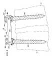
- FIG. 5shows a cut-away view illustrating a stage of installation of an example stabilization device 50 with which embodiments of the displacement device of FIGS. 1-4 may be used in certain procedures. More specifically, FIG. 5 shows a spine stabilization brace assembly that may be introduced into the vertebrae of a patient's spine during a surgical procedure by coupling a brace to a pedicle screw as a single assembly as described further in co-pending and commonly assigned U.S. patent application Ser. No. 10/690,211, filed Oct. 21, 2003, entitled “SYSTEM AND METHOD FOR STABILIZING OF INTERNAL STRUCTURES.” FIG. 5 shows the installation of example stabilization device 50 with respect to vertebrae L4 and L5. Embodiments of a displacement device described herein may be used with other stabilization devices such as that of U.S. Pat. No. 6,530,929 issued to Justis et al., or in procedures that do not involve implanted stabilization devices at all.
- a small incisionmay be made through the skin and a device is used to pinpoint where a pedicle screw, such as pedicle screw 602 , is to be placed.
- Dilatorssuch as dilators 503 and 504 , are introduced until a diameter suitable for passing the pedicle screw and its extensions is achieved.
- braceor “rod” 601 is attached to pedicle screw (“anchor”) 602 to form a brace-screw assembly.
- the assemblyis placed at the distal end of cannula 501 , inserting pedicle screw 602 into a pre-tapped hole in vertebrae L4. Then, pedicle screw (“anchor”) 603 is inserted through cannula 502 into a pre-tapped hole in vertebrae L5. Once these screws are in place, dilators 503 , 504 are removed, and a tool is used to part the muscle bundle below the skin between vertebrae L4 and L5. The muscles and other tissue are only separated to a point where brace 601 may pass. Thus, the procedure may be performed with minimal invasion because no incision is needed between the small incisions by which cannulas 501 , 502 may pass.
- brace 601After separating the muscles, brace 601 is positioned by pivoting brace 601 into position as shown by the arrow pointing downward in FIG. 5 . Again, this procedure will be discussed in further detail later with respect to FIGS. 8 and 9 . However, FIG. 5 shows how brace 601 may be positioned between pedicle screws 602 and 603 . Once brace 601 has been positioned in the area between pedicle screws 602 , 603 , the surgeon may assess what angular and lateral adjustments may be made in the vertebrae L4 and L5, and accordingly, the surgeon may use the displacement device as described with respect to FIGS. 1-4 in order to make these adjustments before locking brace 601 into place.
- brace 601is used for stabilization in this example device, in other devices other types of elements may be used such as a flexible material or a wire.
- a cage, autograft or any other type of interbody fusion devicemay be placed in between the vertebrae bodies. The device could be used with a dynamic stabilization device.
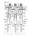
- FIG. 6illustrates the example displacement device 10 in use with the example stabilization device 50 of FIG. 5 .
- the guide tubes 102 and 104 of displacement device 10are placed over anchor extensions 606 and 607 .
- Anchor extensions 606 and 607are removably attached to rod cages 605 and 604 respectively.
- Guides 102 and 104may be displaced relative to each other responsive to manipulation of the user interface (knob 112 in this example).
- cross-action members 106 and 107move which displaces guide tubes 102 and 104 relative to one another.
- guides 102 and 104will either be placed in closer relative position to each other (by compression) or be pushed apart (by distraction).
- guide tubes 102 and 104may be used to perform adjustments to the relative displacement of L4 and L5 after brace 601 is inserted between pedicle screws 602 , 603 but before it is locked down to such pedicle screws using locking caps.
- the pedicle screwscan be moved relative to each other by displacement device 10 , wherein rod cages 605 , 604 are rotated and have angular motion to the heads of the pedicle screws 602 , 603 .
- the pedicle screwsmay be locked into position prior to insertion of locking caps.
- displacement device 10may force a particular angulation on the pedicle screws 602 , 603 even when the pedicle screws have been locked into position.
- a displacement techniquesuch as compression or distraction
- the surgeonmay first perform distraction in order to insert an interbody device. Later the surgeon may compress the vertebrae to embed the interbody device and secure the stabilization device (with set screws) before stitching the incisions made for each of the cannulas.
- the majority of the displacement device 10When in use in the example procedure of FIG. 6 , the majority of the displacement device 10 would not be positioned inside the patient's body. Rather, the skin line typically would be just below the sloped portion 119 , 120 of guide tubes 102 , 104 respectively as shown in FIG. 6 . Because most of the displacement device is located outside the patient's body, smaller incisions may be used because the incisions would only need to be as wide as guide tubes 102 and 104 . Thus, no incision would be needed for insertion of cross-action members 106 , 107 or threaded rod 110 , for example, because no additional incisions are needed over those required for inserting the anchors. This is useful both for the patient and for the surgeon.
- the patientbenefits because smaller incisions are made due to the smaller size of the inserted position of the displacement device, resulting in a potentially faster recovery time.
- the surgeonalso benefits because he/she may perform distraction and subsequently perform compression without having to remove the device from its placement in the patient or without having to switch devices to perform each type of displacement. Further, the portion of the device that the surgeon operates is positioned far enough above the incision line that it is easy for the surgeon to turn knob 112 making it user-friendly to perform the desired displacement technique.
- FIG. 7shows a cut-away view illustrating a stage of stabilizing/fixing the displaced position of L4 and L5 bony structures with the example implanted stabilization device 50 .
- Set screws 701or other locking devices, are introduced down cannulas 501 and 502 to lock each end of brace 601 to its respective pedicle screw 602 , 603 , while displacement device 10 (not shown in FIG. 7 ) maintains the desired displacement of L4 and L5.
- the displacement device 10can be removed.
- the resulting implanted stabilization device 50is shown in FIG. 9 .
- FIG. 8a flow diagram for operation of a displacement device during a spinal procedure according to one embodiment of the invention is shown.
- the flow diagram of FIG. 8will be discussed with reference to the device 50 described above.
- the resulting implanted stabilization device 50is shown in FIG. 9 .
- Assemblies 500 and 700( FIG. 9 ) are coupled to pedicle screws 602 and 603 , respectively in process 801 .
- the pedicle screwsare assembled with the extensions and rod cages prior to insertion into the vertebrae bodies.
- pedicle screws 602 and 603are inserted into vertebrae of a patient's spine, such as vertebrae L4 and L5, respectively.
- Such assemblies 500 and 700each form a receiving member for receiving closure member (e.g., set screw) 701 .
- receiving member formed by assemblies 500 and 700is a noncontiguous (e.g., open-back member) having at least two walls, such as walls 902 and 903 , that are separated by slots.
- closure member 701 and walls 902 and 903are formed to have complementary threads that are formed in an interlocking manner that preferably aids in preventing splaying of the receiving members.
- brace 601is extended from assembly 500 to assembly 700 .
- a surgeonidentifies the desired vertebral levels and pedicle positions via standard techniques. Once the target vertebrae (vertebra levels L4 and L5 in this example) are identified, a small incision is made through the patient's skin and a tracking needle (or other device) is inserted to pinpoint exactly where each screw is to be placed. A fluoroscope, or other x-ray technique, is used to properly position the tracking needle. Once the proper position is located, a first guide wire (K wire) is positioned with its distal end against the pedicle of vertebrae L4, and a second guide wire (K wire) is positioned with its distal end against the pedicle of vertebrae L5. The surgeon then slides a series of continuing larger sized dilators down each of these guide wires.
- K wirefirst guide wire
- K wiresecond guide wire
- a tapis sent down over the K wire to tap a hole into the pedicle in preparation for receiving the anchor, which in this case is a pedicle screw.
- This tapwill usually be a size slightly smaller than the pedicle screw thread size selected for that patient and that level.
- brace 601Prior to inserting the screw, brace 601 is attached to screw 602 to form a brace-screw assembly. This assembly then is positioned at the distal end of a first cannula and a screwdriver or wrench is inserted into the first cannula and attached to the proximal end of brace 601 , and the entire assembly then is inserted into a remaining dilator.
- the screwdriverengages with proximal end 904 of brace 601 so as to allow the surgeon to screw pedicle screw 602 into the pre-tapped hole in vertebrae L5. Pressure on the screwdriver forces the screw to be in-line with the brace, which, in turn, is in-line with the screwdriver.
- assembly 700is adapted to receive the proximal end 904 of brace 601 as is more fully described below.
- both screws 602 and 603are in place in vertebrae L4 and L5, respectively, the remaining dilator is removed, and the surgeon slides a blunt dissection tool into the skin incision and gently parts the muscle bundle below the skin between vertebrae L4 and L5.
- the blunt dissection toolcould go down the second cannula (through which screw 603 was inserted) and, starting at the bottom of the second cannula, work open the muscle bundle between the cannula working upward as far as is necessary.
- the muscles (and other tissue)only need to be separated to a point where the brace 601 must pass. Thus, the separation need not go to the skin level. This reduces patient trauma even further.
- brace 601then is positioned, by pivoting (as described above with respect to FIG. 5 ) and sliding a tool down the first cannula in which it resides to engage the proximal end 904 of brace 601 .
- displacementmay include compression, distraction, or a combination of distraction and compression.
- guide tubes of a displacement deviceare inserted over anchor extensions in process 804 .
- the displacement deviceis inserted over the anchor extensions in the example embodiment, further embodiments provide for additional devices to be inserted over the bone anchor for direct compression and/or distraction.
- Another embodimenthas the displacement device placed over extensions or bone anchors, such as a device for applying force in a direction that is perpendicular to the direction in which distraction or compression occurs, as in a spondylolisthesis reduction. Force is then transmitted to the anchor extensions in order to begin compression or distraction in process 805 . Alternatively, force is transmitted directly to the rod cages in order to begin compression or distraction. The surgeon may engage the displacement mechanism by turning knob 112 , as discussed above with respect to FIG. 1 .
- the surgeonmay choose to place an interbody device into the patient and distract while the device is being inserted.
- the surgeonmay choose to perform distraction before the interbody device is introduced into the patient's body.
- compressionmay be performed in order to ensure that the device is properly positioned relative to the bony structures.
- surgeonmay use as force measurement mechanism or displacement scale device as described with respect to FIG. 8 .
- a devicethen may be used in process 806 to determine if enough compression or distraction has been performed such as a device that will measure how much threaded block 111 has moved relative to threaded rod coupling 108 .
- This device 301(shown in FIG. 3 ) will employ a basic scaling technique where the display of the device may be set at zero, and the device will count incrementally based on the number of turns that knob 112 completes. This typically would be based on a scale where one turn of knob 112 translates into 1 millimeter of advancement, although another scale may be used as desired. The surgeon may view the display of device 301 and determine whether further displacement is desired.
- the level of compression or distractionmay be measured using a force measurement device 302 (as shown in FIG. 2 ).
- This devicepreferably is located inside threaded block 111 , and the device may include a stationary member and a member that may be deflected depending on the amount of force that is created by compression or distraction.
- the device 302may have a display located on the outside of threaded block 111 for the surgeon to view to determine how much force has been exerted.
- FIGUREShave been described with respect to a device that performs both compression and distraction with minimal invasion
- alternative embodimentsmay provide a device that performs compression alone or distraction alone while resulting in minimal invasion of the patient.
- a device to perform compression alonemay be constructed to perform both compression and distraction
- the devicemay be configured so that when the device is loosened following compression, the cross-members disengage and no force is exerted in the opposite direction.
- the devicemay be configured to perform distraction.
- set screws 901are introduced down the first and second cannulas to lock each end of brace 601 to its respective anchor to maintain the desired displacement in process 807 .
- the proximal end 904 of brace 601is snapped in place to screw 602 and set screws 901 are tightened, the displacement device and anchor extensions may be removed and the incision closed in process 808 .
- brace-screw assemblyof brace 601 attached to pedicle screw 602
- a vertebraee.g., vertebrae L5
- brace 601is pivoted such that one end 904 remains positioned over pedicle screw 602 and its opposite end is positioned over pedicle screw 603 is described further in the '211 patent application.
- FIGS. 10 a and 10 bshow alternative embodiments of the present invention where the user interface described with respect to FIG. 1 has been replaced with a set of handles that may be configured to perform compression or distraction. Although the user interface has been altered, the cross-action mechanism and guide tubes as described in FIG. 1 remain the same and are numbered in FIGS. 10 a and 10 b according to their placement in FIG. 1 .
- FIG. 10 athis figure illustrates an example embodiment of a user interface employing handles that are manipulated to result in compression.
- the handle assemblyincludes upper handle 1001 and lower handle 1004 , which are interconnected at a center attachment 1003 .
- Upper handle 1001is joined to lever 1002 which is positioned in a first position 1007 or a second position 1008 depending on whether compression or distraction is desired.
- the first position 1007is used to produce the distraction of the guides.
- the second position 1008is used to produce compression of the guides.
- FIG. 10 bshows an example embodiment of a user interface employing handles that are manipulated to result in distraction.
- upper handle 1001is joined to lever 1002 , but in this case, lever 1002 is positioned in first position 1007 in the slot provided in member 1005 .
- lever 1002is positioned in first position 1007 in the slot provided in member 1005 .
- pivot 1006rotates counter-clockwise (as shown by the arrow on pivot 1006 ), causing guide tubes 102 , 104 to be move apart (as shown by the arrow pointing upward below guide tube 104 ).
- FIG. 11illustrates an example displacement device having more than two guide tubes.
- Guide tubes 102 B and 104are depicted as described above with respect to FIG. 6 .
- Guide tubes 102 B and 104may be displaced relative to each other responsive to manipulation of the user interface (knob 112 B in this example).
- knob 112 BWhen knob 112 B is turned, cross-action members 106 B and 107 B move which displaces guide tubes 102 B and 104 relative to one another, depending on whether compression or distraction is desired.
- Guide tube 104is stationary and guide tube 102 B moves relative to guide tube 104 .
- guide tubes 102 A and 104may be displaced relative to each other responsive to manipulation of the user interface (knob 112 A in this example).
- FIG. 11depicts a displacement device having three guide tubes affixed to three anchors, further embodiments provide for additional guide tubes to be included in the displacement device.
Landscapes
- Health & Medical Sciences (AREA)
- Neurology (AREA)
- Orthopedic Medicine & Surgery (AREA)
- Life Sciences & Earth Sciences (AREA)
- Surgery (AREA)
- Heart & Thoracic Surgery (AREA)
- Engineering & Computer Science (AREA)
- Biomedical Technology (AREA)
- Nuclear Medicine, Radiotherapy & Molecular Imaging (AREA)
- Medical Informatics (AREA)
- Molecular Biology (AREA)
- Animal Behavior & Ethology (AREA)
- General Health & Medical Sciences (AREA)
- Public Health (AREA)
- Veterinary Medicine (AREA)
- Surgical Instruments (AREA)
- Prostheses (AREA)
Abstract
Description
Claims (28)
Priority Applications (5)
| Application Number | Priority Date | Filing Date | Title |
|---|---|---|---|
| US10/837,724US7776051B2 (en) | 2004-05-03 | 2004-05-03 | System and method for displacement of bony structures |
| EP05744243AEP1744694A2 (en) | 2004-05-03 | 2005-05-02 | System and method for displacement of bony structures |
| PCT/US2005/015521WO2005107415A2 (en) | 2004-05-03 | 2005-05-02 | System and method for displacement of bony structures |
| TW094114156ATW200605843A (en) | 2004-05-03 | 2005-05-02 | System and method for displacement of bony structures |
| CA002564405ACA2564405A1 (en) | 2004-05-03 | 2005-05-02 | System and method for displacement of bony structures |
Applications Claiming Priority (1)
| Application Number | Priority Date | Filing Date | Title |
|---|---|---|---|
| US10/837,724US7776051B2 (en) | 2004-05-03 | 2004-05-03 | System and method for displacement of bony structures |
Publications (2)
| Publication Number | Publication Date |
|---|---|
| US20050245928A1 US20050245928A1 (en) | 2005-11-03 |
| US7776051B2true US7776051B2 (en) | 2010-08-17 |
Family
ID=35188070
Family Applications (1)
| Application Number | Title | Priority Date | Filing Date |
|---|---|---|---|
| US10/837,724Expired - Fee RelatedUS7776051B2 (en) | 2004-05-03 | 2004-05-03 | System and method for displacement of bony structures |
Country Status (5)
| Country | Link |
|---|---|
| US (1) | US7776051B2 (en) |
| EP (1) | EP1744694A2 (en) |
| CA (1) | CA2564405A1 (en) |
| TW (1) | TW200605843A (en) |
| WO (1) | WO2005107415A2 (en) |
Cited By (29)
| Publication number | Priority date | Publication date | Assignee | Title |
|---|---|---|---|---|
| US20100036443A1 (en)* | 2007-10-23 | 2010-02-11 | Alphatec Spine, Inc. | Systems and methods for spinal fixation |
| US20110196429A1 (en)* | 2008-10-01 | 2011-08-11 | Sherwin Hua | System and method for wire-guided pedicle screw stabilization of spinal vertebrae |
| US20110319939A1 (en)* | 2010-01-05 | 2011-12-29 | Neuraxis Technologies LLC | Compression-distraction spinal fixation system and kit |
| US20120123301A1 (en)* | 2010-11-12 | 2012-05-17 | Connor Robert A | Spinal motion measurement device |
| US8333770B2 (en) | 2008-10-01 | 2012-12-18 | Sherwin Hua | Systems and methods for pedicle screw stabilization of spinal vertebrae |
| US8603094B2 (en) | 2010-07-26 | 2013-12-10 | Spinal Usa, Inc. | Minimally invasive surgical tower access devices and related methods |
| US20140135776A1 (en)* | 2012-11-09 | 2014-05-15 | Benvenue Medical, Inc. | Disc space sizing devices and methods for using the same |
| US8906034B2 (en) | 2012-04-17 | 2014-12-09 | Alphatec Spine, Inc. | Instrument and method for spinal compression and distraction |
| US9011450B2 (en) | 2012-08-08 | 2015-04-21 | DePuy Synthes Products, LLC | Surgical instrument |
| US9131966B2 (en) | 2013-03-11 | 2015-09-15 | DePuy Synthes Products, Inc. | Vertebral manipulation assembly |
| US9314274B2 (en) | 2011-05-27 | 2016-04-19 | DePuy Synthes Products, Inc. | Minimally invasive spinal fixation system including vertebral alignment features |
| US9402663B2 (en) | 2010-04-23 | 2016-08-02 | DePuy Synthes Products, Inc. | Minimally invasive instrument set, devices and related methods |
| US9498262B2 (en) | 2006-04-11 | 2016-11-22 | DePuy Synthes Products, Inc. | Minimally invasive fixation system |
| US9596428B2 (en) | 2010-03-26 | 2017-03-14 | Echostar Technologies L.L.C. | Multiple input television receiver |
| US9808281B2 (en) | 2009-05-20 | 2017-11-07 | DePuy Synthes Products, Inc. | Patient-mounted retraction |
| US9907582B1 (en) | 2011-04-25 | 2018-03-06 | Nuvasive, Inc. | Minimally invasive spinal fixation system and related methods |
| US10194960B1 (en) | 2015-12-03 | 2019-02-05 | Nuvasive, Inc. | Spinal compression instrument and related methods |
| US11160580B2 (en) | 2019-04-24 | 2021-11-02 | Spine23 Inc. | Systems and methods for pedicle screw stabilization of spinal vertebrae |
| US11224453B2 (en) | 2014-07-08 | 2022-01-18 | Spinal Elements, Inc. | Apparatus and methods for disrupting intervertebral disc tissue |
| US11471145B2 (en) | 2018-03-16 | 2022-10-18 | Spinal Elements, Inc. | Articulated instrumentation and methods of using the same |
| US11564811B2 (en) | 2015-02-06 | 2023-01-31 | Spinal Elements, Inc. | Graft material injector system and method |
| US11583327B2 (en) | 2018-01-29 | 2023-02-21 | Spinal Elements, Inc. | Minimally invasive interbody fusion |
| US11744571B1 (en) | 2022-06-27 | 2023-09-05 | Warsaw Orthopedic, Inc. | Surgical system and method for treating vertebral segments with uneven pedicles |
| US11771483B2 (en) | 2017-03-22 | 2023-10-03 | Spinal Elements, Inc. | Minimal impact access system to disc space |
| USRE49994E1 (en) | 2013-03-14 | 2024-06-04 | Spinal Elements, Inc. | Spinal fusion implants and devices and methods for deploying such implants |
| US12076058B2 (en) | 2021-05-12 | 2024-09-03 | Spine23 Inc. | Systems and methods for pedicle screw stabilization of spinal vertebrae |
| US12251141B2 (en) | 2017-04-21 | 2025-03-18 | The Johns Hopkins University | Vertebral body manipulation device and methods |
| US12268422B2 (en) | 2019-11-27 | 2025-04-08 | Spine23 Inc. | Systems, devices and methods for treating a lateral curvature of a spine |
| US12440248B2 (en) | 2022-06-28 | 2025-10-14 | DePuy Synthes Products, Inc. | Minimally invasive instrument set, devices, and related methods |
Families Citing this family (162)
| Publication number | Priority date | Publication date | Assignee | Title |
|---|---|---|---|---|
| AU2003287273C1 (en) | 2002-10-30 | 2010-01-07 | Zimmer Spine, Inc. | Spinal stabilization system insertion and methods |
| US9539012B2 (en) | 2002-10-30 | 2017-01-10 | Zimmer Spine, Inc. | Spinal stabilization systems with quick-connect sleeve assemblies for use in surgical procedures |
| US20060095035A1 (en)* | 2004-11-03 | 2006-05-04 | Jones Robert J | Instruments and methods for reduction of vertebral bodies |
| US7887539B2 (en) | 2003-01-24 | 2011-02-15 | Depuy Spine, Inc. | Spinal rod approximators |
| TWI315010B (en)* | 2003-03-31 | 2009-09-21 | Sharp Corporatio | Liquid crystal display device and method of manufacturing the same |
| US7955355B2 (en) | 2003-09-24 | 2011-06-07 | Stryker Spine | Methods and devices for improving percutaneous access in minimally invasive surgeries |
| US8002798B2 (en) | 2003-09-24 | 2011-08-23 | Stryker Spine | System and method for spinal implant placement |
| US9055934B2 (en) | 2004-08-26 | 2015-06-16 | Zimmer Spine, Inc. | Methods and apparatus for access to and/or treatment of the spine |
| US20050277934A1 (en)* | 2004-06-10 | 2005-12-15 | Vardiman Arnold B | Rod delivery device and method |
| BRPI0418941A (en)* | 2004-07-06 | 2007-12-04 | Synthes Gmbh | surgical instrument for forcing a longitudinal spinal rod into a bone fixator |
| US7651496B2 (en)* | 2004-07-23 | 2010-01-26 | Zimmer Spine, Inc. | Methods and apparatuses for percutaneous implant delivery |
| US8460310B2 (en) | 2004-08-04 | 2013-06-11 | Leslie Stern | Surgical base unit and retractor support mechanism |
| US7637914B2 (en)* | 2004-08-04 | 2009-12-29 | Leslie Stern | Surgical base unit and retractor support mechanism |
| CA2597944A1 (en)* | 2004-08-15 | 2006-02-23 | Kevin Seex | Distraction and retraction assemblies |
| US7641690B2 (en)* | 2004-08-23 | 2010-01-05 | Abdou M Samy | Bone fixation and fusion device |
| EP1814472B1 (en)* | 2004-09-08 | 2018-10-24 | NuVasive, Inc. | Systems for performing spinal fixation |
| WO2006041963A2 (en) | 2004-10-05 | 2006-04-20 | Abdou M S | Devices and methods for inter-vertebral orthopedic device placement |
| US7935134B2 (en) | 2004-10-20 | 2011-05-03 | Exactech, Inc. | Systems and methods for stabilization of bone structures |
| US8267969B2 (en) | 2004-10-20 | 2012-09-18 | Exactech, Inc. | Screw systems and methods for use in stabilization of bone structures |
| US8162985B2 (en) | 2004-10-20 | 2012-04-24 | The Board Of Trustees Of The Leland Stanford Junior University | Systems and methods for posterior dynamic stabilization of the spine |
| US8025680B2 (en) | 2004-10-20 | 2011-09-27 | Exactech, Inc. | Systems and methods for posterior dynamic stabilization of the spine |
| US8226690B2 (en) | 2005-07-22 | 2012-07-24 | The Board Of Trustees Of The Leland Stanford Junior University | Systems and methods for stabilization of bone structures |
| WO2006058221A2 (en) | 2004-11-24 | 2006-06-01 | Abdou Samy M | Devices and methods for inter-vertebral orthopedic device placement |
| US7811288B2 (en) | 2004-12-02 | 2010-10-12 | Zimmer Spine, Inc. | Instruments and methods for adjusting separation distance of vertebral bodies with a minimally invasive spinal stabilization procedure |
| US7776072B2 (en)* | 2004-12-30 | 2010-08-17 | Barry Mark A | System and method for aligning vertebrae in the amelioration of aberrant spinal column deviation conditions |
| US9339301B2 (en)* | 2004-12-30 | 2016-05-17 | Mark A. Barry | System and method for aligning vertebrae in the amelioration of aberrant spinal column deviation conditions |
| US7951175B2 (en) | 2005-03-04 | 2011-05-31 | Depuy Spine, Inc. | Instruments and methods for manipulating a vertebra |
| US7951172B2 (en) | 2005-03-04 | 2011-05-31 | Depuy Spine Sarl | Constrained motion bone screw assembly |
| ES2318917B1 (en)* | 2005-03-30 | 2010-02-04 | Sdgi Holdings Inc. | SYSTEM FOR THE THREE-DIMENSIONAL CORRECTION OF THE CURVATURE OF THE VERTEBRAL COLUMN IN PROBLEMS OF SCHOLIOSIS BY COPLANAR ALIGNMENT OF THE PEDICULAR SCREWS. |
| US8177817B2 (en) | 2005-05-18 | 2012-05-15 | Stryker Spine | System and method for orthopedic implant configuration |
| US8523865B2 (en) | 2005-07-22 | 2013-09-03 | Exactech, Inc. | Tissue splitter |
| US8870920B2 (en) | 2005-10-07 | 2014-10-28 | M. Samy Abdou | Devices and methods for inter-vertebral orthopedic device placement |
| US7722651B2 (en) | 2005-10-21 | 2010-05-25 | Depuy Spine, Inc. | Adjustable bone screw assembly |
| GB0521582D0 (en) | 2005-10-22 | 2005-11-30 | Depuy Int Ltd | An implant for supporting a spinal column |
| GB0600662D0 (en) | 2006-01-13 | 2006-02-22 | Depuy Int Ltd | Spinal support rod kit |
| US8348952B2 (en) | 2006-01-26 | 2013-01-08 | Depuy International Ltd. | System and method for cooling a spinal correction device comprising a shape memory material for corrective spinal surgery |
| EP1981422B1 (en) | 2006-02-06 | 2018-10-24 | Stryker European Holdings I, LLC | Rod contouring apparatus for percutaneous pedicle screw extension |
| US7655008B2 (en)* | 2006-02-09 | 2010-02-02 | Warsaw Orthopedic, Inc. | Methods and instruments for spinal derotation |
| US7794464B2 (en)* | 2006-02-09 | 2010-09-14 | Warsaw Orthopedic, Inc. | Spinal derotation instruments and methods |
| WO2007118177A2 (en) | 2006-04-06 | 2007-10-18 | Synthes (U.S.A.) | Remotely adjustable tissue displacement device |
| US20080015601A1 (en)* | 2006-06-14 | 2008-01-17 | Michael Castro | Reduction device and method of use |
| US8262569B2 (en)* | 2006-07-19 | 2012-09-11 | Zimmer Spine, Inc. | Surgical access system and method of using the same |
| US7892174B2 (en)* | 2006-07-19 | 2011-02-22 | Zimmer Spine, Inc. | Surgical access system and method of using the same |
| US8303630B2 (en) | 2006-07-27 | 2012-11-06 | Samy Abdou | Devices and methods for the minimally invasive treatment of spinal stenosis |
| DE602007008112D1 (en)* | 2006-09-25 | 2010-09-09 | Stryker Spine | ALIGNMENT CONNECTION FOR BAR CONTOURING |
| US8157809B2 (en)* | 2006-09-25 | 2012-04-17 | Stryker Spine | Percutaneous compression and distraction system |
| US8038699B2 (en)* | 2006-09-26 | 2011-10-18 | Ebi, Llc | Percutaneous instrument assembly |
| US8162952B2 (en)* | 2006-09-26 | 2012-04-24 | Ebi, Llc | Percutaneous instrument assembly |
| US8096996B2 (en) | 2007-03-20 | 2012-01-17 | Exactech, Inc. | Rod reducer |
| US20090082775A1 (en)* | 2006-10-25 | 2009-03-26 | Moti Altarac | Spondylolisthesis reduction system and method |
| US9101401B2 (en)* | 2006-11-20 | 2015-08-11 | Aesculap Implant Systems, Llc | Bone repair device and method |
| US20080119862A1 (en)* | 2006-11-21 | 2008-05-22 | Wicker Meleah Ann | Surgical Instrument for Supplying a Counter-Torque When Securing a Spinal Prosthesis |
| US20080132766A1 (en)* | 2006-12-05 | 2008-06-05 | Zimmer Spine, Inc. | Surgical Access System And Method Of Using Same |
| US7922731B2 (en)* | 2006-12-22 | 2011-04-12 | Aesculap Ag | Surgical instrument and osteosynthesis device |
| US7998144B2 (en)* | 2006-12-22 | 2011-08-16 | Aesculap Ag | Surgical instrument and osteosynthesis device |
| US8202302B2 (en)* | 2007-04-19 | 2012-06-19 | Mi4Spine, Llc | Pedicle screw and rod system |
| US8016832B2 (en)* | 2007-05-02 | 2011-09-13 | Zimmer Spine, Inc. | Installation systems for spinal stabilization system and related methods |
| EP3009089B1 (en)* | 2007-05-18 | 2017-06-21 | Stryker European Holdings I, LLC | System for direct vertebral rotation |
| US8043343B2 (en)* | 2007-06-28 | 2011-10-25 | Zimmer Spine, Inc. | Stabilization system and method |
| US8900237B2 (en)* | 2007-08-31 | 2014-12-02 | DePuy Synthes Products, LLC | Minimally invasive guide system |
| US8512343B2 (en)* | 2007-08-31 | 2013-08-20 | DePuy Synthes Products, LLC | Methods and instruments for approximating misaligned vertebra |
| US8888819B2 (en)* | 2007-08-31 | 2014-11-18 | DePuy Synthes Products, LLC | Connector for securing an offset spinal fixation element |
| WO2009055026A1 (en)* | 2007-10-23 | 2009-04-30 | Alphatec Spine, Inc. | Systems and methods for spinal fixation |
| US8821502B2 (en)* | 2007-10-23 | 2014-09-02 | Alphatec Spine, Inc. | Instrument and method for spinal compression and distraction |
| GB0720762D0 (en) | 2007-10-24 | 2007-12-05 | Depuy Spine Sorl | Assembly for orthopaedic surgery |
| US9402665B2 (en)* | 2008-01-11 | 2016-08-02 | Trimed, Incorporated | Expansion and compression instrument for fracture fixation |
| CA2781407A1 (en) | 2008-01-14 | 2009-07-23 | Michael P. Brenzel | Apparatus and methods for fracture repair |
| US8439922B1 (en) | 2008-02-06 | 2013-05-14 | NiVasive, Inc. | Systems and methods for holding and implanting bone anchors |
| US8709015B2 (en) | 2008-03-10 | 2014-04-29 | DePuy Synthes Products, LLC | Bilateral vertebral body derotation system |
| US8608746B2 (en) | 2008-03-10 | 2013-12-17 | DePuy Synthes Products, LLC | Derotation instrument with reduction functionality |
| SE533231C2 (en)* | 2008-05-28 | 2010-07-27 | Ortoviva Ab | Moving device, its use and a system therefor |
| US8900248B2 (en)* | 2008-06-13 | 2014-12-02 | The University Of Toledo | Insertion assembly for minimally invasive spinal surgery |
| US10973556B2 (en) | 2008-06-17 | 2021-04-13 | DePuy Synthes Products, Inc. | Adjustable implant assembly |
| EP2337510B1 (en) | 2008-06-25 | 2018-10-31 | Stryker European Holdings I, LLC | Surgical instrumentation for implanting a prothesis |
| US8287546B2 (en) | 2008-07-31 | 2012-10-16 | Zimmer Spine, Inc. | Surgical instrument with integrated compression and distraction mechanisms |
| US9066763B2 (en) | 2008-07-31 | 2015-06-30 | Zimmer Spine, Inc. | Surgical instrument with integrated reduction and distraction mechanisms |
| US8075565B2 (en)* | 2008-11-05 | 2011-12-13 | Warsaw Orthopedic, Inc. | Surgical instruments for delivering forces to bony structures |
| US9161787B2 (en)* | 2009-04-23 | 2015-10-20 | The Johns Hopkins University | Vertebral body reduction instrument and methods related thereto |
| US9655658B2 (en) | 2009-10-14 | 2017-05-23 | Ebi, Llc | Deformable device for minimally invasive fixation |
| US8277453B2 (en)* | 2009-10-30 | 2012-10-02 | Warsaw Orthopedic, Inc. | Instruments and systems for vertebral column manipulation |
| US8795335B1 (en) | 2009-11-06 | 2014-08-05 | Samy Abdou | Spinal fixation devices and methods of use |
| DE112010004338B4 (en) | 2009-11-10 | 2019-06-27 | Nuvasive, Inc. | DEVICE FOR IMPLEMENTING SPINE SURGERY |
| US8747309B2 (en)* | 2010-11-09 | 2014-06-10 | Covidien Lp | Suspension system for minimally invasive surgery |
| US8764806B2 (en) | 2009-12-07 | 2014-07-01 | Samy Abdou | Devices and methods for minimally invasive spinal stabilization and instrumentation |
| US20110178520A1 (en) | 2010-01-15 | 2011-07-21 | Kyle Taylor | Rotary-rigid orthopaedic rod |
| US8545505B2 (en)* | 2010-01-15 | 2013-10-01 | Pioneer Surgical Technology, Inc. | Low friction rod persuader |
| US8636655B1 (en) | 2010-01-19 | 2014-01-28 | Ronald Childs | Tissue retraction system and related methods |
| WO2011091052A1 (en) | 2010-01-20 | 2011-07-28 | Kyle Taylor | Apparatus and methods for bone access and cavity preparation |
| US8540719B2 (en)* | 2010-02-09 | 2013-09-24 | Aesculap Implant Systems, Llc | Percutaneous rod insertion system and method |
| WO2011112615A1 (en) | 2010-03-08 | 2011-09-15 | Krinke Todd A | Apparatus and methods for securing a bone implant |
| US8512383B2 (en) | 2010-06-18 | 2013-08-20 | Spine Wave, Inc. | Method of percutaneously fixing a connecting rod to a spine |
| US8394108B2 (en) | 2010-06-18 | 2013-03-12 | Spine Wave, Inc. | Screw driver for a multiaxial bone screw |
| US8777954B2 (en) | 2010-06-18 | 2014-07-15 | Spine Wave, Inc. | Pedicle screw extension for use in percutaneous spinal fixation |
| US8454664B2 (en) | 2010-06-18 | 2013-06-04 | Spine Wave, Inc. | Method for fixing a connecting rod to a thoracic spine |
| US8206395B2 (en) | 2010-06-18 | 2012-06-26 | Spine Wave, Inc. | Surgical instrument and method for the distraction or compression of bones |
| CN102293680B (en) | 2010-06-24 | 2014-04-16 | 华沙整形外科股份有限公司 | Coplanar straightening system |
| DE102010032465A1 (en)* | 2010-07-28 | 2012-02-02 | Richard Martin Sellei | Mounting aid for improved and biomechanically optimized assembly of external pelvic ring fixator, comprises repositioning device which is provided for reduction of anterior pelvic ring fracture |
| US8702713B2 (en)* | 2011-01-26 | 2014-04-22 | Warsaw Orthopedic, Inc. | Instruments and techniques for adjusting relative positioning of bones or bony tissues |
| US9198698B1 (en) | 2011-02-10 | 2015-12-01 | Nuvasive, Inc. | Minimally invasive spinal fixation system and related methods |
| US9307972B2 (en) | 2011-05-10 | 2016-04-12 | Nuvasive, Inc. | Method and apparatus for performing spinal fusion surgery |
| US8491588B2 (en)* | 2011-06-13 | 2013-07-23 | Warsaw Orthopedic, Inc. | Surgical instrument for securing a spinal rod |
| US8845728B1 (en) | 2011-09-23 | 2014-09-30 | Samy Abdou | Spinal fixation devices and methods of use |
| US9333012B2 (en)* | 2011-10-25 | 2016-05-10 | Warsaw Orthopedic, Inc. | Spinal implant system and method |
| US8911442B2 (en)* | 2011-10-26 | 2014-12-16 | Alphatec Spine, Inc. | Systems for vertebral adjustments and rod reduction |
| US10166048B2 (en) | 2011-11-02 | 2019-01-01 | Tenzin Llc | Translational instrumentation for spondylolisthesis and scoliosis reduction |
| US8936599B2 (en)* | 2011-11-02 | 2015-01-20 | Tenzin Llc | Translational instrumentation for spondylolisthesis and scoliosis reduction |
| US9125703B2 (en)* | 2012-01-16 | 2015-09-08 | K2M, Inc. | Rod reducer, compressor, distractor system |
| US8936626B1 (en) | 2012-02-17 | 2015-01-20 | Nuvasive, Inc. | Bi-cortical screw fixation |
| US20130226240A1 (en) | 2012-02-22 | 2013-08-29 | Samy Abdou | Spinous process fixation devices and methods of use |
| US9561062B2 (en)* | 2012-03-19 | 2017-02-07 | Alphatec Spine, Inc. | Spondylolisthesis reduction system |
| AU2013200369A1 (en)* | 2012-03-29 | 2013-10-17 | Trimed, Incorporated | Expansion and compression instrument for fracture fixation |
| US10098665B2 (en) | 2012-08-01 | 2018-10-16 | DePuy Synthes Products, Inc. | Spine derotation system |
| DE102012107056A1 (en)* | 2012-08-01 | 2014-05-15 | Aesculap Ag | Surgical instruments |
| US9179957B2 (en) | 2012-08-09 | 2015-11-10 | Spinecraft, LLC | Systems, assemblies and methods for spinal derotation |
| US9572598B2 (en) | 2012-08-09 | 2017-02-21 | Spine Craft, LLC | Uniplanar surgical screw assembly |
| US9198767B2 (en) | 2012-08-28 | 2015-12-01 | Samy Abdou | Devices and methods for spinal stabilization and instrumentation |
| EP2722021B1 (en)* | 2012-10-20 | 2017-12-13 | K2M, Inc. | Lateral distractor |
| US9320617B2 (en) | 2012-10-22 | 2016-04-26 | Cogent Spine, LLC | Devices and methods for spinal stabilization and instrumentation |
| US9763702B2 (en) | 2012-11-16 | 2017-09-19 | DePuy Synthes Products, Inc. | Bone fixation assembly |
| US9827020B2 (en) | 2013-03-14 | 2017-11-28 | Stryker European Holdings I, Llc | Percutaneous spinal cross link system and method |
| CA2846149C (en) | 2013-03-14 | 2018-03-20 | Stryker Spine | Systems and methods for percutaneous spinal fusion |
| US9668789B2 (en) | 2013-03-15 | 2017-06-06 | Ebi, Llc | Reduction instrument, surgical assembly including a reduction instrument and related method |
| US9173687B2 (en)* | 2013-03-15 | 2015-11-03 | DePuy Synthes Products, Inc. | Fulcrum cap for spinal constructs |
| CN114983546A (en) | 2013-05-13 | 2022-09-02 | 尼奥医疗公司 | Orthopedic implant kit |
| US9295500B2 (en) | 2013-06-12 | 2016-03-29 | Spine Wave, Inc. | Screw driver with release for a multiaxial bone screw |
| US9402660B2 (en) | 2013-09-05 | 2016-08-02 | Warsaw Orthopedic, Inc. | Surgical instrument and method |
| US9744050B1 (en)* | 2013-12-06 | 2017-08-29 | Stryker European Holdings I, Llc | Compression and distraction system for percutaneous posterior spinal fusion |
| US10159579B1 (en) | 2013-12-06 | 2018-12-25 | Stryker European Holdings I, Llc | Tubular instruments for percutaneous posterior spinal fusion systems and methods |
| US9408716B1 (en) | 2013-12-06 | 2016-08-09 | Stryker European Holdings I, Llc | Percutaneous posterior spinal fusion implant construction and method |
| CN105939677A (en) | 2013-12-12 | 2016-09-14 | 康文图斯整形外科公司 | Tissue displacement tools and methods |
| CA2874390C (en) | 2013-12-13 | 2018-03-06 | Stryker European Holdings I, Llc | Tissue retraction and vertebral displacement devices, systems, and methods for posterior spinal fusion |
| US9795370B2 (en) | 2014-08-13 | 2017-10-24 | Nuvasive, Inc. | Minimally disruptive retractor and associated methods for spinal surgery |
| US10028772B2 (en)* | 2014-10-07 | 2018-07-24 | Alphatec Spine, Inc. | Osteotomy instrument |
| CA3008161C (en) | 2014-12-09 | 2023-09-26 | John A. Heflin | Spine alignment system |
| US9974577B1 (en) | 2015-05-21 | 2018-05-22 | Nuvasive, Inc. | Methods and instruments for performing leveraged reduction during single position spine surgery |
| DE102015212056B3 (en)* | 2015-06-29 | 2016-09-01 | Silony Medical International AG | Apparatus for performing distraction or compression of vertebral bodies in a spinal surgery |
| US9439692B1 (en)* | 2015-10-09 | 2016-09-13 | Spine Wave, Inc. | Minimally invasive spinal fixation system and method therefor |
| US10857003B1 (en) | 2015-10-14 | 2020-12-08 | Samy Abdou | Devices and methods for vertebral stabilization |
| WO2017122163A1 (en)* | 2016-01-15 | 2017-07-20 | Neo Medical Sa | Combined distraction and compression clamp for surgical operations |
| US10194958B2 (en) | 2016-04-27 | 2019-02-05 | Warsaw Othopedic, Inc. | Spinal correction system and method |
| US11051859B2 (en) | 2016-04-27 | 2021-07-06 | Warsaw Orthopedic, Inc. | Spinal correction system and method |
| USD842479S1 (en) | 2016-04-27 | 2019-03-05 | Warsaw Orthopedic, Inc. | Spinal implant |
| WO2018004813A1 (en)* | 2016-07-01 | 2018-01-04 | Nuvasive, Inc. | Spinal trauma correction and fixation |
| US10543022B2 (en) | 2016-10-11 | 2020-01-28 | Warsaw Orthopedic, Inc. | Spinal implant system and method |
| US10973648B1 (en) | 2016-10-25 | 2021-04-13 | Samy Abdou | Devices and methods for vertebral bone realignment |
| US10744000B1 (en) | 2016-10-25 | 2020-08-18 | Samy Abdou | Devices and methods for vertebral bone realignment |
| US10779866B2 (en) | 2016-12-29 | 2020-09-22 | K2M, Inc. | Rod reducer assembly |
| CN106725790B (en)* | 2017-01-16 | 2019-06-28 | 于大鹏 | A kind of universal resetting apparatus of centrum for orthopedic spinal surgery |
| WO2018150214A1 (en)* | 2017-02-17 | 2018-08-23 | Warsaw Orthopedic, Inc. | Surgical system |
| US11484349B2 (en)* | 2017-02-17 | 2022-11-01 | Warsaw Orthopedic, Inc. | Surgical system and method |
| WO2019010252A2 (en) | 2017-07-04 | 2019-01-10 | Conventus Orthopaedics, Inc. | APPARATUS AND METHODS FOR TREATING BONES |
| US10952714B1 (en) | 2017-07-14 | 2021-03-23 | OrtoWay AB | Apparatus, methods and systems for spine surgery |
| US11013607B2 (en) | 2017-09-22 | 2021-05-25 | Encore Medical, L.P. | Talar ankle implant |
| EP3501432A1 (en) | 2017-12-20 | 2019-06-26 | Stryker European Holdings I, LLC | Joint instrumentation |
| EP3517062B1 (en)* | 2018-01-26 | 2021-03-17 | Aesculap AG | Spinal repositioning instrument and spinal repositioning system |
| US20190231394A1 (en)* | 2018-01-29 | 2019-08-01 | Globus Medical, Inc. | Compressor/distractor |
| DE102018116177A1 (en)* | 2018-07-04 | 2020-01-09 | Silony Medical International AG | Bone fracture correction device |
| US10646261B2 (en) | 2018-07-24 | 2020-05-12 | Warsaw Orthopedic, Inc. | Multi-purpose screwdriver and method of use |
| US11179248B2 (en) | 2018-10-02 | 2021-11-23 | Samy Abdou | Devices and methods for spinal implantation |
| US11617602B2 (en) | 2020-04-16 | 2023-04-04 | Medtronic, Inc. | Systems, methods of use and surgical instruments employing a secure slide lock to fasten a head |
| US11439442B2 (en) | 2020-04-16 | 2022-09-13 | Warsaw Orthopedic, Inc. | Modular screw system with head locker and derotator |
| CN114652421B (en)* | 2022-02-10 | 2024-06-14 | 山东威高骨科材料股份有限公司 | Minimally invasive centrum lifting and resetting device |
Citations (40)
| Publication number | Priority date | Publication date | Assignee | Title |
|---|---|---|---|---|
| US4025053A (en) | 1976-05-10 | 1977-05-24 | Stickle Jr Warren Edward | Screw actuated scissor jack with a self adjusting bearing surface |
| EP0159007A2 (en) | 1984-04-16 | 1985-10-23 | Kluger, Patrick, Dr. med. | Apparatus for the treatment of the spinal column |
| US4827918A (en) | 1985-08-15 | 1989-05-09 | Sven Olerud | Fixing instrument for use in spinal surgery |
| US4926849A (en) | 1986-12-19 | 1990-05-22 | Downey Ernest L | Apparatus for separating vertebrae |
| US5163940A (en)* | 1991-03-04 | 1992-11-17 | American Cyanamid Company | Surgical drill guide for tibia |
| US5167662A (en) | 1992-01-24 | 1992-12-01 | Zimmer, Inc. | Temporary clamp and inserter for a posterior midline spinal clamp |
| US5297538A (en) | 1992-04-10 | 1994-03-29 | Daniel Elie C | Surgical retractor/compressor |
| US5395303A (en) | 1990-07-30 | 1995-03-07 | Peter M. Bonutti | Orthosis with distraction through range of motion |
| US5439463A (en) | 1993-11-12 | 1995-08-08 | Lin; Chih-I | Spinal clamping device |
| US5443515A (en) | 1994-01-26 | 1995-08-22 | Implex Corporation | Vertebral body prosthetic implant with slidably positionable stabilizing member |
| US5466237A (en) | 1993-11-19 | 1995-11-14 | Cross Medical Products, Inc. | Variable locking stabilizer anchor seat and screw |
| US5474555A (en) | 1990-04-26 | 1995-12-12 | Cross Medical Products | Spinal implant system |
| US5540687A (en) | 1993-05-19 | 1996-07-30 | Fairley; Jeffrey D. | Device for the distraction of bones |
| US5700263A (en) | 1996-06-17 | 1997-12-23 | Schendel; Stephen A. | Bone distraction apparatus |
| US6090113A (en) | 1996-12-27 | 2000-07-18 | Stryker France S.A. | Adjustable osteosynthesis system of the rachis |
| US6126660A (en) | 1998-07-29 | 2000-10-03 | Sofamor Danek Holdings, Inc. | Spinal compression and distraction devices and surgical methods |
| US6340363B1 (en) | 1998-10-09 | 2002-01-22 | Surgical Navigation Technologies, Inc. | Image guided vertebral distractor and method for tracking the position of vertebrae |
| US20020123754A1 (en)* | 2001-02-28 | 2002-09-05 | Holmes Russell P. | Instrument for bone distraction and compression having ratcheting tips |
| US6530929B1 (en) | 1999-10-20 | 2003-03-11 | Sdgi Holdings, Inc. | Instruments for stabilization of bony structures |
| US6551316B1 (en) | 2001-03-02 | 2003-04-22 | Beere Precision Medical Instruments, Inc. | Selective compression and distraction instrument |
| US20030153911A1 (en) | 2002-02-13 | 2003-08-14 | Endius Incorporated | Apparatus for connecting a longitudinal member to a bone portion |
| WO2004047650A2 (en) | 2002-11-23 | 2004-06-10 | Sdgi Holdings, Inc. | Istraction and retraction system for spinal surgery |
| US6749613B1 (en) | 1999-02-18 | 2004-06-15 | Stryker Spine | Distraction/contraction device for spinal osteosynthesis system |
| US20040143265A1 (en) | 2002-10-30 | 2004-07-22 | Landry Michael E. | Spinal stabilization systems and methods using minimally invasive surgical procedures |
| US6802844B2 (en) | 2001-03-26 | 2004-10-12 | Nuvasive, Inc | Spinal alignment apparatus and methods |
| US20040267279A1 (en) | 2003-04-24 | 2004-12-30 | Simon Casutt | Distance measuring instrument for pedicle screws |
| US6837889B2 (en) | 2002-03-01 | 2005-01-04 | Endius Incorporated | Apparatus for connecting a longitudinal member to a bone portion |
| US20050070917A1 (en) | 2003-09-29 | 2005-03-31 | Justis Jeff R. | Instruments and methods for securing a connecting element along a bony segment |
| US20050080418A1 (en) | 2001-10-30 | 2005-04-14 | Simonson Robert E. | Instruments and methods for minimally invasive spine surgery |
| US20050131422A1 (en) | 2003-12-16 | 2005-06-16 | Anderson David G. | Methods and devices for spinal fixation element placement |
| US20050131421A1 (en) | 2003-12-16 | 2005-06-16 | Anderson David G. | Methods and devices for minimally invasive spinal fixation element placement |
| US20050131408A1 (en) | 2003-12-16 | 2005-06-16 | Sicvol Christopher W. | Percutaneous access devices and bone anchor assemblies |
| US20050277919A1 (en) | 2004-05-28 | 2005-12-15 | Depuy Spine, Inc. | Anchoring systems and methods for correcting spinal deformities |
| WO2005120401A2 (en) | 2004-06-02 | 2005-12-22 | Facet Solutions, Inc. | Surgical measurement and resection framework |
| WO2005122926A1 (en) | 2004-06-09 | 2005-12-29 | Zimmer Spine, Inc. | Spinal fixation device with internal drive structure |
| US20060009777A1 (en) | 2004-07-06 | 2006-01-12 | Roy Lim | Systems and methods for compressing and distracting vertebrae of the spinal column |
| US7008432B2 (en) | 1999-12-10 | 2006-03-07 | Synthes | Device for distracting or compressing bones on bone fragments |
| US7011658B2 (en) | 2002-03-04 | 2006-03-14 | Sdgi Holdings, Inc. | Devices and methods for spinal compression and distraction |
| US20060149252A1 (en) | 2004-12-30 | 2006-07-06 | Markworth Aaron D | Bone anchorage screw with built-in hinged plate |
| US7160300B2 (en)* | 2004-02-27 | 2007-01-09 | Jackson Roger P | Orthopedic implant rod reduction tool set and method |
- 2004
- 2004-05-03USUS10/837,724patent/US7776051B2/ennot_activeExpired - Fee Related
- 2005
- 2005-05-02WOPCT/US2005/015521patent/WO2005107415A2/enactiveApplication Filing
- 2005-05-02TWTW094114156Apatent/TW200605843A/enunknown
- 2005-05-02EPEP05744243Apatent/EP1744694A2/ennot_activeWithdrawn
- 2005-05-02CACA002564405Apatent/CA2564405A1/ennot_activeAbandoned
Patent Citations (44)
| Publication number | Priority date | Publication date | Assignee | Title |
|---|---|---|---|---|
| US4025053A (en) | 1976-05-10 | 1977-05-24 | Stickle Jr Warren Edward | Screw actuated scissor jack with a self adjusting bearing surface |
| EP0159007A2 (en) | 1984-04-16 | 1985-10-23 | Kluger, Patrick, Dr. med. | Apparatus for the treatment of the spinal column |
| US4827918A (en) | 1985-08-15 | 1989-05-09 | Sven Olerud | Fixing instrument for use in spinal surgery |
| US4926849A (en) | 1986-12-19 | 1990-05-22 | Downey Ernest L | Apparatus for separating vertebrae |
| US5474555A (en) | 1990-04-26 | 1995-12-12 | Cross Medical Products | Spinal implant system |
| US5395303A (en) | 1990-07-30 | 1995-03-07 | Peter M. Bonutti | Orthosis with distraction through range of motion |
| US5163940A (en)* | 1991-03-04 | 1992-11-17 | American Cyanamid Company | Surgical drill guide for tibia |
| US5167662A (en) | 1992-01-24 | 1992-12-01 | Zimmer, Inc. | Temporary clamp and inserter for a posterior midline spinal clamp |
| US5297538A (en) | 1992-04-10 | 1994-03-29 | Daniel Elie C | Surgical retractor/compressor |
| US5540687A (en) | 1993-05-19 | 1996-07-30 | Fairley; Jeffrey D. | Device for the distraction of bones |
| US5439463A (en) | 1993-11-12 | 1995-08-08 | Lin; Chih-I | Spinal clamping device |
| US5466237A (en) | 1993-11-19 | 1995-11-14 | Cross Medical Products, Inc. | Variable locking stabilizer anchor seat and screw |
| US5443515A (en) | 1994-01-26 | 1995-08-22 | Implex Corporation | Vertebral body prosthetic implant with slidably positionable stabilizing member |
| US5700263A (en) | 1996-06-17 | 1997-12-23 | Schendel; Stephen A. | Bone distraction apparatus |
| US6090113A (en) | 1996-12-27 | 2000-07-18 | Stryker France S.A. | Adjustable osteosynthesis system of the rachis |
| US6126660A (en) | 1998-07-29 | 2000-10-03 | Sofamor Danek Holdings, Inc. | Spinal compression and distraction devices and surgical methods |
| US6340363B1 (en) | 1998-10-09 | 2002-01-22 | Surgical Navigation Technologies, Inc. | Image guided vertebral distractor and method for tracking the position of vertebrae |
| US6749613B1 (en) | 1999-02-18 | 2004-06-15 | Stryker Spine | Distraction/contraction device for spinal osteosynthesis system |
| US6530929B1 (en) | 1999-10-20 | 2003-03-11 | Sdgi Holdings, Inc. | Instruments for stabilization of bony structures |
| US7008422B2 (en)* | 1999-10-20 | 2006-03-07 | Sdgi Holdings, Inc. | Instruments and methods for stabilization of bony structures |
| US7188626B2 (en)* | 1999-10-20 | 2007-03-13 | Warsaw Orthopedic, Inc. | Instruments and methods for stabilization of bony structures |
| US7008432B2 (en) | 1999-12-10 | 2006-03-07 | Synthes | Device for distracting or compressing bones on bone fragments |
| US20020123754A1 (en)* | 2001-02-28 | 2002-09-05 | Holmes Russell P. | Instrument for bone distraction and compression having ratcheting tips |
| US6716218B2 (en) | 2001-02-28 | 2004-04-06 | Hol-Med Corporation | Instrument for bone distraction and compression having ratcheting tips |
| US6551316B1 (en) | 2001-03-02 | 2003-04-22 | Beere Precision Medical Instruments, Inc. | Selective compression and distraction instrument |
| US6802844B2 (en) | 2001-03-26 | 2004-10-12 | Nuvasive, Inc | Spinal alignment apparatus and methods |
| US20050080418A1 (en) | 2001-10-30 | 2005-04-14 | Simonson Robert E. | Instruments and methods for minimally invasive spine surgery |
| US20040176766A1 (en) | 2002-02-13 | 2004-09-09 | Shluzas Alan E. | Apparatus for connecting a longitudinal member to a bone portion |
| US20030153911A1 (en) | 2002-02-13 | 2003-08-14 | Endius Incorporated | Apparatus for connecting a longitudinal member to a bone portion |
| US6837889B2 (en) | 2002-03-01 | 2005-01-04 | Endius Incorporated | Apparatus for connecting a longitudinal member to a bone portion |
| US7011658B2 (en) | 2002-03-04 | 2006-03-14 | Sdgi Holdings, Inc. | Devices and methods for spinal compression and distraction |
| US20040143265A1 (en) | 2002-10-30 | 2004-07-22 | Landry Michael E. | Spinal stabilization systems and methods using minimally invasive surgical procedures |
| WO2004047650A2 (en) | 2002-11-23 | 2004-06-10 | Sdgi Holdings, Inc. | Istraction and retraction system for spinal surgery |
| US20040267279A1 (en) | 2003-04-24 | 2004-12-30 | Simon Casutt | Distance measuring instrument for pedicle screws |
| US20050070917A1 (en) | 2003-09-29 | 2005-03-31 | Justis Jeff R. | Instruments and methods for securing a connecting element along a bony segment |
| US20050131408A1 (en) | 2003-12-16 | 2005-06-16 | Sicvol Christopher W. | Percutaneous access devices and bone anchor assemblies |
| US20050131421A1 (en) | 2003-12-16 | 2005-06-16 | Anderson David G. | Methods and devices for minimally invasive spinal fixation element placement |
| US20050131422A1 (en) | 2003-12-16 | 2005-06-16 | Anderson David G. | Methods and devices for spinal fixation element placement |
| US7160300B2 (en)* | 2004-02-27 | 2007-01-09 | Jackson Roger P | Orthopedic implant rod reduction tool set and method |
| US20050277919A1 (en) | 2004-05-28 | 2005-12-15 | Depuy Spine, Inc. | Anchoring systems and methods for correcting spinal deformities |
| WO2005120401A2 (en) | 2004-06-02 | 2005-12-22 | Facet Solutions, Inc. | Surgical measurement and resection framework |
| WO2005122926A1 (en) | 2004-06-09 | 2005-12-29 | Zimmer Spine, Inc. | Spinal fixation device with internal drive structure |
| US20060009777A1 (en) | 2004-07-06 | 2006-01-12 | Roy Lim | Systems and methods for compressing and distracting vertebrae of the spinal column |
| US20060149252A1 (en) | 2004-12-30 | 2006-07-06 | Markworth Aaron D | Bone anchorage screw with built-in hinged plate |
Non-Patent Citations (1)
| Title |
|---|
| International Search Report and Written Opinion issued for PCT/US2005/015521 dated Dec. 12, 2005. |
Cited By (57)
| Publication number | Priority date | Publication date | Assignee | Title |
|---|---|---|---|---|
| US9498262B2 (en) | 2006-04-11 | 2016-11-22 | DePuy Synthes Products, Inc. | Minimally invasive fixation system |
| US10441325B2 (en) | 2006-04-11 | 2019-10-15 | DePuy Synthes Products, Inc. | Minimally invasive fixation system |
| US8394109B2 (en)* | 2007-10-23 | 2013-03-12 | Alphatec Spine, Inc. | Systems and methods for spinal fixation |
| US20100036443A1 (en)* | 2007-10-23 | 2010-02-11 | Alphatec Spine, Inc. | Systems and methods for spinal fixation |
| US10973551B2 (en) | 2008-10-01 | 2021-04-13 | Sherwin Hua | Systems and methods for pedicle screw stabilization of spinal vertebrae |
| US8216282B2 (en) | 2008-10-01 | 2012-07-10 | Sherwin Hua | System and method for wire-guided pedicle screw stabilization of spinal vertebrae |
| US8545541B2 (en) | 2008-10-01 | 2013-10-01 | Sherwin Hua | System and method for wire-guided pedicle screw stabilization of spinal vertebrae |
| US8556940B2 (en) | 2008-10-01 | 2013-10-15 | Sherwin Hua | System and method for wire-guided pedicle screw stabilization of spinal vertebrae |
| US20110196429A1 (en)* | 2008-10-01 | 2011-08-11 | Sherwin Hua | System and method for wire-guided pedicle screw stabilization of spinal vertebrae |
| US8721691B2 (en) | 2008-10-01 | 2014-05-13 | Sherwin Hua | Systems and methods for pedicle screw stabilization of spinal vertebrae |
| US8333770B2 (en) | 2008-10-01 | 2012-12-18 | Sherwin Hua | Systems and methods for pedicle screw stabilization of spinal vertebrae |
| US11759238B2 (en) | 2008-10-01 | 2023-09-19 | Sherwin Hua | Systems and methods for pedicle screw stabilization of spinal vertebrae |
| US10993739B2 (en) | 2009-05-20 | 2021-05-04 | DePuy Synthes Products, Inc. | Patient-mounted retraction |
| US9808281B2 (en) | 2009-05-20 | 2017-11-07 | DePuy Synthes Products, Inc. | Patient-mounted retraction |
| US12349936B2 (en) | 2009-05-20 | 2025-07-08 | DePuy Synthes Products, Inc. | Patient-mounted retraction |
| US8968367B2 (en)* | 2010-01-05 | 2015-03-03 | The Johns Hopkins University | Compression-distraction spinal fixation system and kit |
| US20110319939A1 (en)* | 2010-01-05 | 2011-12-29 | Neuraxis Technologies LLC | Compression-distraction spinal fixation system and kit |
| US9596428B2 (en) | 2010-03-26 | 2017-03-14 | Echostar Technologies L.L.C. | Multiple input television receiver |
| US11389213B2 (en) | 2010-04-23 | 2022-07-19 | DePuy Synthes Products, Inc. | Minimally invasive instrument set, devices, and related methods |
| US9402663B2 (en) | 2010-04-23 | 2016-08-02 | DePuy Synthes Products, Inc. | Minimally invasive instrument set, devices and related methods |
| US10888360B2 (en) | 2010-04-23 | 2021-01-12 | DePuy Synthes Products, Inc. | Minimally invasive instrument set, devices, and related methods |
| US9220543B2 (en) | 2010-07-26 | 2015-12-29 | Spinal Usa, Inc. | Minimally invasive surgical tower access devices and related methods |
| US8603094B2 (en) | 2010-07-26 | 2013-12-10 | Spinal Usa, Inc. | Minimally invasive surgical tower access devices and related methods |
| US20120123301A1 (en)* | 2010-11-12 | 2012-05-17 | Connor Robert A | Spinal motion measurement device |
| US8721566B2 (en)* | 2010-11-12 | 2014-05-13 | Robert A. Connor | Spinal motion measurement device |
| US11596453B2 (en) | 2011-04-25 | 2023-03-07 | Nuvasive, Inc. | Minimally invasive spinal fixation system |
| US12357350B2 (en) | 2011-04-25 | 2025-07-15 | Nuvasive, Inc. | Minimally invasive spinal fixation system and related methods |
| US9907582B1 (en) | 2011-04-25 | 2018-03-06 | Nuvasive, Inc. | Minimally invasive spinal fixation system and related methods |
| US10716600B1 (en) | 2011-04-25 | 2020-07-21 | Nuvasive, Inc. | Minimally invasive spinal fixation system |
| US10098666B2 (en) | 2011-05-27 | 2018-10-16 | DePuy Synthes Products, Inc. | Minimally invasive spinal fixation system including vertebral alignment features |
| US9314274B2 (en) | 2011-05-27 | 2016-04-19 | DePuy Synthes Products, Inc. | Minimally invasive spinal fixation system including vertebral alignment features |
| US8906034B2 (en) | 2012-04-17 | 2014-12-09 | Alphatec Spine, Inc. | Instrument and method for spinal compression and distraction |
| US9011450B2 (en) | 2012-08-08 | 2015-04-21 | DePuy Synthes Products, LLC | Surgical instrument |
| US9955961B2 (en)* | 2012-11-09 | 2018-05-01 | Benvenue Medical, Inc. | Disc space sizing devices |
| US20160256148A1 (en)* | 2012-11-09 | 2016-09-08 | Benvenue Medical, Inc. | Disc Space Sizing Devices And Methods Of Using The Same |
| US9351851B2 (en)* | 2012-11-09 | 2016-05-31 | Bevenue Medical, Inc. | Disc space sizing devices and methods for using the same |
| US20140135776A1 (en)* | 2012-11-09 | 2014-05-15 | Benvenue Medical, Inc. | Disc space sizing devices and methods for using the same |
| US9131966B2 (en) | 2013-03-11 | 2015-09-15 | DePuy Synthes Products, Inc. | Vertebral manipulation assembly |
| USRE49994E1 (en) | 2013-03-14 | 2024-06-04 | Spinal Elements, Inc. | Spinal fusion implants and devices and methods for deploying such implants |
| US11224453B2 (en) | 2014-07-08 | 2022-01-18 | Spinal Elements, Inc. | Apparatus and methods for disrupting intervertebral disc tissue |
| US12053196B2 (en) | 2014-07-08 | 2024-08-06 | Spinal Elements, Inc. | Apparatus and methods for disrupting inter vertebral disc tissue |
| US11564811B2 (en) | 2015-02-06 | 2023-01-31 | Spinal Elements, Inc. | Graft material injector system and method |
| US12121456B2 (en) | 2015-02-06 | 2024-10-22 | Spinal Elements, Inc. | Graft material injector system and method |
| US10194960B1 (en) | 2015-12-03 | 2019-02-05 | Nuvasive, Inc. | Spinal compression instrument and related methods |
| US12070252B2 (en) | 2015-12-03 | 2024-08-27 | Nuvasive, Inc. | Spinal compression instrument and related methods |
| US11006983B2 (en) | 2015-12-03 | 2021-05-18 | Nuvasive, Inc. | Spinal compression instrument and related methods |
| US11771483B2 (en) | 2017-03-22 | 2023-10-03 | Spinal Elements, Inc. | Minimal impact access system to disc space |
| US12251141B2 (en) | 2017-04-21 | 2025-03-18 | The Johns Hopkins University | Vertebral body manipulation device and methods |
| US11583327B2 (en) | 2018-01-29 | 2023-02-21 | Spinal Elements, Inc. | Minimally invasive interbody fusion |
| US12207856B2 (en) | 2018-01-29 | 2025-01-28 | Spinal Elements, Inc. | Minimally invasive interbody fusion |
| US12357291B2 (en) | 2018-03-16 | 2025-07-15 | Spinal Elements, Inc. | Articulated instrumentation and methods of using the same |
| US11471145B2 (en) | 2018-03-16 | 2022-10-18 | Spinal Elements, Inc. | Articulated instrumentation and methods of using the same |
| US11160580B2 (en) | 2019-04-24 | 2021-11-02 | Spine23 Inc. | Systems and methods for pedicle screw stabilization of spinal vertebrae |
| US12268422B2 (en) | 2019-11-27 | 2025-04-08 | Spine23 Inc. | Systems, devices and methods for treating a lateral curvature of a spine |
| US12076058B2 (en) | 2021-05-12 | 2024-09-03 | Spine23 Inc. | Systems and methods for pedicle screw stabilization of spinal vertebrae |
| US11744571B1 (en) | 2022-06-27 | 2023-09-05 | Warsaw Orthopedic, Inc. | Surgical system and method for treating vertebral segments with uneven pedicles |
| US12440248B2 (en) | 2022-06-28 | 2025-10-14 | DePuy Synthes Products, Inc. | Minimally invasive instrument set, devices, and related methods |
Also Published As
| Publication number | Publication date |
|---|---|
| EP1744694A2 (en) | 2007-01-24 |
| TW200605843A (en) | 2006-02-16 |
| WO2005107415A2 (en) | 2005-11-17 |
| WO2005107415A3 (en) | 2006-01-26 |
| US20050245928A1 (en) | 2005-11-03 |
| CA2564405A1 (en) | 2005-11-17 |
Similar Documents
| Publication | Publication Date | Title |
|---|---|---|
| US7776051B2 (en) | System and method for displacement of bony structures | |
| US11633216B2 (en) | Spondylisthesis reduction system | |
| US12185990B2 (en) | Spinal alignment frame | |
| US10441325B2 (en) | Minimally invasive fixation system | |
| US10098666B2 (en) | Minimally invasive spinal fixation system including vertebral alignment features | |
| US7419499B2 (en) | Spinal stabilization implant and method of application | |
| US7588588B2 (en) | System and method for stabilizing of internal structures | |
| US8394109B2 (en) | Systems and methods for spinal fixation | |
| US20080077155A1 (en) | System and method for displacement of bony structures | |
| US12349890B2 (en) | Surgical system and method |
Legal Events
| Date | Code | Title | Description |
|---|---|---|---|
| AS | Assignment | Owner name:INNOVATIVE SPINAL TECHNOLOGIES, TEXAS Free format text:ASSIGNMENT OF ASSIGNORS INTEREST;ASSIGNORS:COLLERAN, DENNIS;DIEDERICH, JENNIFER;REEL/FRAME:015298/0819 Effective date:20040503 | |
| AS | Assignment | Owner name:SILICON VALLEY BANK, AS AGENT AND AS A LENDER, MAS Free format text:SECURITY AGREEMENT;ASSIGNOR:INNOVATIVE SPINAL TECHNOLOGIES, INC.;REEL/FRAME:021750/0493 Effective date:20080912 Owner name:GE BUSINESS FINANCIAL SERVICES INC., F/K/A MERRILL Free format text:SECURITY AGREEMENT;ASSIGNOR:INNOVATIVE SPINAL TECHNOLOGIES, INC.;REEL/FRAME:021750/0493 Effective date:20080912 Owner name:SILICON VALLEY BANK, AS AGENT AND AS A LENDER,MASS Free format text:SECURITY AGREEMENT;ASSIGNOR:INNOVATIVE SPINAL TECHNOLOGIES, INC.;REEL/FRAME:021750/0493 Effective date:20080912 | |
| AS | Assignment | Owner name:THEKEN SPINE, LLC, OHIO Free format text:TERMINATION AND RELEASE OF SECURITY INTEREST;ASSIGNORS:SILICON VALLEY BANK;GE BUSINESS FINANCIAL SERVICES, INC.;REEL/FRAME:023228/0001 Effective date:20090910 Owner name:THEKEN SPINE, LLC,OHIO Free format text:TERMINATION AND RELEASE OF SECURITY INTEREST;ASSIGNORS:SILICON VALLEY BANK;GE BUSINESS FINANCIAL SERVICES, INC.;REEL/FRAME:023228/0001 Effective date:20090910 | |
| AS | Assignment | Owner name:THEKEN SPINE, LLC, OHIO Free format text:ASSIGNMENT OF ASSIGNORS INTEREST;ASSIGNOR:WARREN E. AGIN, QUALIFIED CHAPTER 7 TRUSTEE IN BANKRUPTCY FOR INNOVATIVE SPINAL TECHNOLOGIES, INC.;REEL/FRAME:023233/0395 Effective date:20090910 Owner name:THEKEN SPINE, LLC,OHIO Free format text:ASSIGNMENT OF ASSIGNORS INTEREST;ASSIGNOR:WARREN E. AGIN, QUALIFIED CHAPTER 7 TRUSTEE IN BANKRUPTCY FOR INNOVATIVE SPINAL TECHNOLOGIES, INC.;REEL/FRAME:023233/0395 Effective date:20090910 | |
| REMI | Maintenance fee reminder mailed | ||
| LAPS | Lapse for failure to pay maintenance fees | ||
| STCH | Information on status: patent discontinuation | Free format text:PATENT EXPIRED DUE TO NONPAYMENT OF MAINTENANCE FEES UNDER 37 CFR 1.362 | |
| FP | Lapsed due to failure to pay maintenance fee | Effective date:20140817 |