US7776050B2 - Insertion instrument for a pair of sliding prostheses - Google Patents
Insertion instrument for a pair of sliding prosthesesDownload PDFInfo
- Publication number
- US7776050B2 US7776050B2US10/912,225US91222504AUS7776050B2US 7776050 B2US7776050 B2US 7776050B2US 91222504 AUS91222504 AUS 91222504AUS 7776050 B2US7776050 B2US 7776050B2
- Authority
- US
- United States
- Prior art keywords
- support plate
- instrument
- clamps
- clamp
- spacing
- Prior art date
- Legal status (The legal status is an assumption and is not a legal conclusion. Google has not performed a legal analysis and makes no representation as to the accuracy of the status listed.)
- Expired - Fee Related, expires
Links
- 238000003780insertionMethods0.000titleclaimsabstractdescription6
- 230000037431insertionEffects0.000titleclaimsabstractdescription6
- 230000008878couplingEffects0.000claimsabstractdescription26
- 238000010168coupling processMethods0.000claimsabstractdescription26
- 238000005859coupling reactionMethods0.000claimsabstractdescription26
- 238000001356surgical procedureMethods0.000claims3
- 239000004568cementSubstances0.000description2
- 230000008093supporting effectEffects0.000description2
- 238000006073displacement reactionMethods0.000description1
- 210000000629knee jointAnatomy0.000description1
Images

Classifications
- A—HUMAN NECESSITIES
- A61—MEDICAL OR VETERINARY SCIENCE; HYGIENE
- A61F—FILTERS IMPLANTABLE INTO BLOOD VESSELS; PROSTHESES; DEVICES PROVIDING PATENCY TO, OR PREVENTING COLLAPSING OF, TUBULAR STRUCTURES OF THE BODY, e.g. STENTS; ORTHOPAEDIC, NURSING OR CONTRACEPTIVE DEVICES; FOMENTATION; TREATMENT OR PROTECTION OF EYES OR EARS; BANDAGES, DRESSINGS OR ABSORBENT PADS; FIRST-AID KITS
- A61F2/00—Filters implantable into blood vessels; Prostheses, i.e. artificial substitutes or replacements for parts of the body; Appliances for connecting them with the body; Devices providing patency to, or preventing collapsing of, tubular structures of the body, e.g. stents
- A61F2/02—Prostheses implantable into the body
- A61F2/30—Joints
- A61F2/46—Special tools for implanting artificial joints
- A61F2/4603—Special tools for implanting artificial joints for insertion or extraction of endoprosthetic joints or of accessories thereof
- A61F2/461—Special tools for implanting artificial joints for insertion or extraction of endoprosthetic joints or of accessories thereof of knees
- A—HUMAN NECESSITIES
- A61—MEDICAL OR VETERINARY SCIENCE; HYGIENE
- A61F—FILTERS IMPLANTABLE INTO BLOOD VESSELS; PROSTHESES; DEVICES PROVIDING PATENCY TO, OR PREVENTING COLLAPSING OF, TUBULAR STRUCTURES OF THE BODY, e.g. STENTS; ORTHOPAEDIC, NURSING OR CONTRACEPTIVE DEVICES; FOMENTATION; TREATMENT OR PROTECTION OF EYES OR EARS; BANDAGES, DRESSINGS OR ABSORBENT PADS; FIRST-AID KITS
- A61F2/00—Filters implantable into blood vessels; Prostheses, i.e. artificial substitutes or replacements for parts of the body; Appliances for connecting them with the body; Devices providing patency to, or preventing collapsing of, tubular structures of the body, e.g. stents
- A61F2/02—Prostheses implantable into the body
- A61F2/30—Joints
- A61F2/38—Joints for elbows or knees
- A61F2/3859—Femoral components
- A—HUMAN NECESSITIES
- A61—MEDICAL OR VETERINARY SCIENCE; HYGIENE
- A61F—FILTERS IMPLANTABLE INTO BLOOD VESSELS; PROSTHESES; DEVICES PROVIDING PATENCY TO, OR PREVENTING COLLAPSING OF, TUBULAR STRUCTURES OF THE BODY, e.g. STENTS; ORTHOPAEDIC, NURSING OR CONTRACEPTIVE DEVICES; FOMENTATION; TREATMENT OR PROTECTION OF EYES OR EARS; BANDAGES, DRESSINGS OR ABSORBENT PADS; FIRST-AID KITS
- A61F2/00—Filters implantable into blood vessels; Prostheses, i.e. artificial substitutes or replacements for parts of the body; Appliances for connecting them with the body; Devices providing patency to, or preventing collapsing of, tubular structures of the body, e.g. stents
- A61F2/02—Prostheses implantable into the body
- A61F2/30—Joints
- A61F2/38—Joints for elbows or knees
- A61F2002/3895—Joints for elbows or knees unicompartimental
- A—HUMAN NECESSITIES
- A61—MEDICAL OR VETERINARY SCIENCE; HYGIENE
- A61F—FILTERS IMPLANTABLE INTO BLOOD VESSELS; PROSTHESES; DEVICES PROVIDING PATENCY TO, OR PREVENTING COLLAPSING OF, TUBULAR STRUCTURES OF THE BODY, e.g. STENTS; ORTHOPAEDIC, NURSING OR CONTRACEPTIVE DEVICES; FOMENTATION; TREATMENT OR PROTECTION OF EYES OR EARS; BANDAGES, DRESSINGS OR ABSORBENT PADS; FIRST-AID KITS
- A61F2/00—Filters implantable into blood vessels; Prostheses, i.e. artificial substitutes or replacements for parts of the body; Appliances for connecting them with the body; Devices providing patency to, or preventing collapsing of, tubular structures of the body, e.g. stents
- A61F2/02—Prostheses implantable into the body
- A61F2/30—Joints
- A61F2/46—Special tools for implanting artificial joints
- A61F2/4603—Special tools for implanting artificial joints for insertion or extraction of endoprosthetic joints or of accessories thereof
- A61F2002/4625—Special tools for implanting artificial joints for insertion or extraction of endoprosthetic joints or of accessories thereof with relative movement between parts of the instrument during use
- A61F2002/4628—Special tools for implanting artificial joints for insertion or extraction of endoprosthetic joints or of accessories thereof with relative movement between parts of the instrument during use with linear motion along or rotating motion about an axis transverse to the instrument axis or to the implantation direction, e.g. clamping
Definitions
- the human knee-jointcomprises two pairs of tibio-femoral articular surfaces, namely a medial pair of articular surfaces and a lateral pair of articular surfaces, which are in each case formed by a femoral condyle and by a dish-shaped tibial articular surface interacting with said femoral condyle. It is known (EP-A-1099430) to replace the articular surfaces of the femoral condyles individually by a slide prosthesis and, for this purpose, to use an insertion instrument which guarantees the exact mutual alignment of the prostheses.
- the prosthesesare held on the instrument by means of clamps which are secured on a support plate of the instrument via a releasable coupling.
- the releasable couplingconsists of a plug on each clamp and of two receiving openings in the support plate, into which openings these plugs can be inserted with an exact fit. They are secured therein by means of screws which remain accessible during the operation so that they can be undone when the instrument is to be removed from the clamps.
- the object of the inventionis to make available an insertion instrument for sliding prostheses which is of the type first mentioned above and which permits different spacings of the clamps and allows them to be separated from the instrument during the operation.
- the coupling between the claims and the support plateis provided in any the clamps and the position in the LM direction, at least on one of the two clamps, so that the clamp in question can be set to a different spacing from the other clamp, and a fixing means is provided for fixing the clamp in the chosen position.
- the coupling provided in any position in the LM directioncan, like the known solutions, consist of a plug on the clamp and of an elongate hole arranged in the support plate and receiving the plug.
- the clampis guided on the support plate in such a way that it is allowed only a lateral movement of adjustment (in the LM direction).
- Both clampsare expediently connected to the support plate via in each case a coupling provided in any position in the LM direction and can be fixed in the chosen position. This is intended to ensure that the two clamps can each be arranged symmetrically with respect to the instrument axis.
- the inventionprovides for a fixing yoke whose ends, transverse to the adjustment direction and release direction of the couplings, press on a coupling part connected to the clamps, namely preferably on the coupling plug.
- the fixing yokeis connected centrally to the support plate by a pressing means, for example a screw, which can be actuated during the operation. In this way, it is possible to release the coupling during the operation and, if appropriate, close it again after changing the spacing of the clamps. It is not necessary for the fixing yoke to act on the coupling part, which is to be held, exactly perpendicular to the adjustment and release directions. However, this is generally advantageous.
- the fixing yokeis, like the coupling, expediently provided in any position in the LM direction, in order to be able to secure the clamps at any desired spacing. If one wishes to permit only certain spacings, for example ones which are in accord with certain tibial prosthesis parts (see, for example, EP-A-1099430), the fixing yoke can also be designed such that it can act on the coupling parts of the clamp plugs only at the desired spacings.
- the yokecan be provided with projections or indents which match recesses or projections on the plugs. It is also possible to provide several exchangeable fixing yokes, of which each one can interact with the associated clamp plugs only at a predetermined clamp spacing and thus acts as spacing gauge.
- the spacing gaugeis on the one hand used for fixing on the support plate at a predetermined position. On the other hand, it has recesses or projections interacting with the clamp plugs or parts thereof to define position.
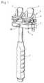
- FIG. 1shows an overall view of the instrument
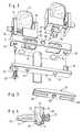
- FIG. 2shows the main parts of the instrument head in a partially exploded view
- FIG. 3shows the fixing yoke
- FIG. 4shows a partial section through the instrument.
- the sliding prostheses 5are shown obliquely from the dorsal-medial direction in FIG. 1 and obliquely from the ventral direction in FIG. 2 .
- the same direction designationsare also applied below to the instrument.
- the support plate 2 of the instrument head 3is secured on a handle with grip 1 .
- the support plate 2supports two clamps 4 for two sliding prostheses 5 , and two slide-surface supports 6 .
- the slide-surface supports 6consist of a threaded shaft, mounted in the support plate 2 , and of a head with an impact cushion of rigidly elastic plastic. By turning them, they can be adjusted so that their top face bears with a supporting action on the slide surface of the prosthesis part located in the associated clamp 4 .
- Each clamp 4comprises a first clamping jaw 10 and a second clamping jaw 11 .
- the foot 12 of the first clamping jaw 10sits fully on the top face of the support plate 2 and is held by it in a manner which will be explained later.
- the second clamping jaw 11is held by the foot 12 of the first clamping jaw 10 so as to be displaceable in parallel.
- the spacing of the clamping jaws 10 , 11 from one anothercan be adjusted by means of a threaded spindle 16 .
- Both clamping jaws 10 , 11carry projections which interact with corresponding recesses of the prostheses 5 when the latter are inserted into the clamps 4 . In this way, the prostheses are positioned in a defined manner relative to the instrument. Details of this design and of this mode of operation can be found in EP-A-1099430.
- each clamp foot 12Protruding from the underside of each clamp foot 12 there is a plug 13 of rectangular profile which at its lower end carries a small cylindrical attachment 14 .
- the support plate 2comprises two elongate holes 15 into which a rectangular plug 13 fits exactly in each case.
- the elongate holes 15 and the plugs 13form interacting guides in the LM direction of the instrument.
- Each clamp 4can therefore adopt different, positions along its line of displacement in the LM direction on the support plate 2 .
- the rectangular plugs 13 and the elongate holes 15form the abovementioned releasable coupling between the clamps 4 and the support plate 2 .
- the plug 13 of rectangular profileis accommodated completely by the associated elongate hole 15 .
- Several spacing gauges 18are made available whose symmetrically arranged bores 17 have a different spacing from one another.
- the latterOn the dorsal face of the support plate 2 , the latter is provided with elongate cutouts 25 in the area of the elongate holes 15 . These cutouts 25 correspond to projections 26 on a fixing yoke 27 which is applied on the dorsal face of the support plate 2 with projections 26 protruding into the cutouts 25 . It is held thereon by means of a threaded screw 30 which passes through the bore 28 of the support plate and engages in the centrally arranged threaded bore 29 of the fixing yoke 27 and whose head is accessible on the ventral face of the support plate 2 .
- the fixing yoke 27When the fixing yoke 27 is drawn onto the rear face of the supporting plate by means of the screw 30 , its projections 26 pass through the cutouts 25 and into the elongate holes 15 (see FIG. 4 ) and press against the rectangular plugs 13 of the clamps 4 present there, by which means these clamps are fixed in their respective position.
- the rectangular plugs 13are provided, on the dorsal face, with a transversely extending, shallow groove 31 into which the front of the projections 26 of the fixing yoke 27 engages.
- the instrumentis used in the following way. Depending on the desired prosthesis spacing, a spacing gauge 18 is selected and is connected to the underside of the support plate 2 .
- the fixing yoke 27is loosely fastened on the rear face of the support plate 2 by means of the screw 30 so that its projections 26 pass into the cutouts 25 but not yet into the area of the elongate holes 15 .
- the clamps 4are then fitted so that their rectangular plugs 13 lie in the elongate holes 15 and their small cylindrical attachments 14 lie in the bores 17 of the spacing gauge 18 .
- the fixing yoke 27is then drawn tight with the screw 30 .
- the clampsare now held secure on the top face of the support plate and at the desired spacing. Thereafter, the prostheses 5 are inserted into the clamps 4 . If so desired, this can also be done before the clamps 4 are connected to the support plate 2 .
- the spacing gauge 18is removed and the screws 30 are carefully loosened so that the clamps 4 can be moved in the LM direction on the support plate 2 . If the projections 26 still engage in the groove 31 , they are secured against falling out. Another spacing gauge 18 can now be connected to the support plate, the clamps 4 at the same time being moved so that their cylindrical attachments 14 engage in the newly positioned holes 17 of the spacing gauge 18 . Thereafter, the fixing yoke 27 is tightened again.
- the coupling of the instrument between the clamps 4 and the support plate 2is released.
- the screw 30is loosened so that the instrument with the support plate 2 can be withdrawn from the clamps in the caudal direction. This can be done before any cement that is used has hardened.
Landscapes
- Health & Medical Sciences (AREA)
- Transplantation (AREA)
- Orthopedic Medicine & Surgery (AREA)
- Life Sciences & Earth Sciences (AREA)
- General Health & Medical Sciences (AREA)
- Oral & Maxillofacial Surgery (AREA)
- Engineering & Computer Science (AREA)
- Biomedical Technology (AREA)
- Heart & Thoracic Surgery (AREA)
- Vascular Medicine (AREA)
- Physical Education & Sports Medicine (AREA)
- Animal Behavior & Ethology (AREA)
- Cardiology (AREA)
- Public Health (AREA)
- Veterinary Medicine (AREA)
- Prostheses (AREA)
- Sawing (AREA)
- Wire Bonding (AREA)
- Mutual Connection Of Rods And Tubes (AREA)
- Dental Prosthetics (AREA)
Abstract
Description
Claims (12)
Applications Claiming Priority (3)
| Application Number | Priority Date | Filing Date | Title |
|---|---|---|---|
| EP03018049.1 | 2003-08-07 | ||
| EP03018049 | 2003-08-07 | ||
| EP03018049AEP1504734B1 (en) | 2003-08-07 | 2003-08-07 | Insertion instrument for sliding prostheses |
Publications (2)
| Publication Number | Publication Date |
|---|---|
| US20050033306A1 US20050033306A1 (en) | 2005-02-10 |
| US7776050B2true US7776050B2 (en) | 2010-08-17 |
Family
ID=33547658
Family Applications (1)
| Application Number | Title | Priority Date | Filing Date |
|---|---|---|---|
| US10/912,225Expired - Fee RelatedUS7776050B2 (en) | 2003-08-07 | 2004-08-06 | Insertion instrument for a pair of sliding prostheses |
Country Status (6)
| Country | Link |
|---|---|
| US (1) | US7776050B2 (en) |
| EP (1) | EP1504734B1 (en) |
| CN (1) | CN1579343B (en) |
| AT (1) | ATE308949T1 (en) |
| DE (1) | DE50301622D1 (en) |
| ES (1) | ES2252598T3 (en) |
Families Citing this family (4)
| Publication number | Priority date | Publication date | Assignee | Title |
|---|---|---|---|---|
| DE20310433U1 (en)* | 2003-07-08 | 2003-09-04 | Aesculap AG & Co. KG, 78532 Tuttlingen | Surgical device for inserting dual component implant into appropriate space at spine, comprising particularly shaped holding area |
| RU2341232C1 (en)* | 2007-03-06 | 2008-12-20 | Федеральное государственное учреждение "Российский научно-исследовательский институт травматологии и ортопедии им. Р.П.Вредена Федерального агентства по высокотехнологичной медицинской помощи ФГУ "РНИИТО им. Р.Р. Вредена Росмедтехнологий" | Device for treatment of marrowy channel of tubular bones after excision of bound total endoprosthesises of knee joint in conditions of wound fever |
| GB2471501B (en)* | 2009-07-01 | 2014-04-09 | Biomet Uk Ltd | a surgical impactor |
| GB201011035D0 (en)* | 2010-07-01 | 2010-08-18 | Finsbury Dev Ltd | An impactor |
Citations (5)
| Publication number | Priority date | Publication date | Assignee | Title |
|---|---|---|---|---|
| US4364389A (en)* | 1980-03-19 | 1982-12-21 | Waldemar Link Gmbh & Co. | Instrument for holding and inserting the tibia plate for an endo-knee prosthesis having sliding surfaces |
| US5902339A (en)* | 1996-08-19 | 1999-05-11 | Waldemar Link (Gmbh & Co) | Method and device for inserting and positioning a prosthesis |
| EP1099430A1 (en) | 1999-11-09 | 2001-05-16 | Waldemar Link (GmbH & Co.) | Knee prosthesis system |
| EP1321116A1 (en) | 2001-12-10 | 2003-06-25 | Waldemar Link (GmbH & Co.) | Insertion instrument for femoral sled prosthesis |
| DE10335410A1 (en)* | 2003-08-01 | 2005-02-24 | Aesculap Ag & Co. Kg | Device for stretching knee area for evaluation of tension of ligaments, comprising specifically shaped lifting elements |
Family Cites Families (1)
| Publication number | Priority date | Publication date | Assignee | Title |
|---|---|---|---|---|
| GB1485771A (en)* | 1973-09-07 | 1977-09-14 | Nat Res Dev | Prosthetic bone joint devices |
- 2003
- 2003-08-07ESES03018049Tpatent/ES2252598T3/ennot_activeExpired - Lifetime
- 2003-08-07DEDE50301622Tpatent/DE50301622D1/ennot_activeExpired - Lifetime
- 2003-08-07ATAT03018049Tpatent/ATE308949T1/enactive
- 2003-08-07EPEP03018049Apatent/EP1504734B1/ennot_activeExpired - Lifetime
- 2004
- 2004-08-06USUS10/912,225patent/US7776050B2/ennot_activeExpired - Fee Related
- 2004-08-09CNCN200410056088.5Apatent/CN1579343B/ennot_activeExpired - Fee Related
Patent Citations (6)
| Publication number | Priority date | Publication date | Assignee | Title |
|---|---|---|---|---|
| US4364389A (en)* | 1980-03-19 | 1982-12-21 | Waldemar Link Gmbh & Co. | Instrument for holding and inserting the tibia plate for an endo-knee prosthesis having sliding surfaces |
| US5902339A (en)* | 1996-08-19 | 1999-05-11 | Waldemar Link (Gmbh & Co) | Method and device for inserting and positioning a prosthesis |
| EP1099430A1 (en) | 1999-11-09 | 2001-05-16 | Waldemar Link (GmbH & Co.) | Knee prosthesis system |
| US6743258B1 (en)* | 1999-11-09 | 2004-06-01 | Waldemar Link (Gmbh & Co.) | Knee prosthesis system |
| EP1321116A1 (en) | 2001-12-10 | 2003-06-25 | Waldemar Link (GmbH & Co.) | Insertion instrument for femoral sled prosthesis |
| DE10335410A1 (en)* | 2003-08-01 | 2005-02-24 | Aesculap Ag & Co. Kg | Device for stretching knee area for evaluation of tension of ligaments, comprising specifically shaped lifting elements |
Also Published As
| Publication number | Publication date |
|---|---|
| US20050033306A1 (en) | 2005-02-10 |
| EP1504734B1 (en) | 2005-11-09 |
| DE50301622D1 (en) | 2005-12-15 |
| CN1579343A (en) | 2005-02-16 |
| EP1504734A1 (en) | 2005-02-09 |
| ES2252598T3 (en) | 2006-05-16 |
| CN1579343B (en) | 2010-11-03 |
| ATE308949T1 (en) | 2005-11-15 |
Similar Documents
| Publication | Publication Date | Title |
|---|---|---|
| JP4125518B2 (en) | Knee prosthesis system | |
| US7048742B2 (en) | Insertion instrument for sliding prostheses | |
| AU737097B2 (en) | Method and apparatus for femoral resection | |
| EP0378294B1 (en) | Femoral surface shaping guide for knee implants | |
| US7201755B2 (en) | Apparatus for the preparation of a femoral condyle | |
| US7632279B2 (en) | Patella resection clamp | |
| US5021055A (en) | Patellar clamp and surgical saw guide | |
| US5951564A (en) | Orthopaedic positioning apparatus | |
| CA2376019C (en) | Tibial plateau resection guide | |
| US8273093B2 (en) | Instrumentation for recording and replicating orthopaedic implant orientation | |
| US6033410A (en) | Orthopaedic instrumentation | |
| US5997543A (en) | Surgical instrumentation | |
| JP4713472B2 (en) | End prosthesis system with cervical prosthesis and insertion device | |
| US8986306B2 (en) | Patella orthopaedic surgical method | |
| US7527630B2 (en) | Apparatus for the preparation of a femoral condyle | |
| US10945777B2 (en) | Surgical instrument and method for performing an orthopaedic surgical procedure | |
| EP2540239A1 (en) | Patella drill guide and clamp assembly | |
| EP2540234A1 (en) | Patella resection guide with locating features | |
| EP2540233A1 (en) | Patella orthopaedic surgical instrument assembly | |
| JP2007506477A (en) | Instrument for inserting a cervical prosthesis | |
| US7776050B2 (en) | Insertion instrument for a pair of sliding prostheses | |
| CN109152578B (en) | Surgical device for performing an operation on a knee of a human being | |
| JP2735468B2 (en) | Method for forming surface of distal part of femur and apparatus used for the method | |
| JP2024048372A (en) | Modular instrument system for use in knee replacement surgery | |
| CN110709018A (en) | Jigs for knee replacement surgery |
Legal Events
| Date | Code | Title | Description |
|---|---|---|---|
| AS | Assignment | Owner name:WALDEAR LINK GMBH & CO. KG, GERMANY Free format text:ASSIGNMENT OF ASSIGNORS INTEREST;ASSIGNOR:KELLER, ARNOLD;REEL/FRAME:015668/0067 Effective date:20040713 | |
| AS | Assignment | Owner name:WALDEMAR LINK GMBH & CO. KG,GERMANY Free format text:CORRECTIVE ASSIGNMENT TO CORRECT THE ASSIGNEE'S NAME, WALDEMAR LINK GMBH & CO. KG PREVIOUSLY RECORDED ON REEL 015668 FRAME 0067. ASSIGNOR(S) HEREBY CONFIRMS THE ASSIGNMENT TO WALDEMAR LINK GMBH & CO. KG;ASSIGNOR:KELLER, ARNOLD;REEL/FRAME:024606/0858 Effective date:20040713 Owner name:WALDEMAR LINK GMBH & CO. KG, GERMANY Free format text:CORRECTIVE ASSIGNMENT TO CORRECT THE ASSIGNEE'S NAME, WALDEMAR LINK GMBH & CO. KG PREVIOUSLY RECORDED ON REEL 015668 FRAME 0067. ASSIGNOR(S) HEREBY CONFIRMS THE ASSIGNMENT TO WALDEMAR LINK GMBH & CO. KG;ASSIGNOR:KELLER, ARNOLD;REEL/FRAME:024606/0858 Effective date:20040713 | |
| FEPP | Fee payment procedure | Free format text:PAYOR NUMBER ASSIGNED (ORIGINAL EVENT CODE: ASPN); ENTITY STATUS OF PATENT OWNER: LARGE ENTITY | |
| FPAY | Fee payment | Year of fee payment:4 | |
| FEPP | Fee payment procedure | Free format text:MAINTENANCE FEE REMINDER MAILED (ORIGINAL EVENT CODE: REM.) | |
| LAPS | Lapse for failure to pay maintenance fees | Free format text:PATENT EXPIRED FOR FAILURE TO PAY MAINTENANCE FEES (ORIGINAL EVENT CODE: EXP.); ENTITY STATUS OF PATENT OWNER: LARGE ENTITY | |
| STCH | Information on status: patent discontinuation | Free format text:PATENT EXPIRED DUE TO NONPAYMENT OF MAINTENANCE FEES UNDER 37 CFR 1.362 | |
| FP | Lapsed due to failure to pay maintenance fee | Effective date:20180817 |