US7776034B2 - Ablation catheter with adjustable virtual electrode - Google Patents
Ablation catheter with adjustable virtual electrodeDownload PDFInfo
- Publication number
- US7776034B2 US7776034B2US11/154,098US15409805AUS7776034B2US 7776034 B2US7776034 B2US 7776034B2US 15409805 AUS15409805 AUS 15409805AUS 7776034 B2US7776034 B2US 7776034B2
- Authority
- US
- United States
- Prior art keywords
- catheter
- fluid
- fluid manifold
- ablation
- section
- Prior art date
- Legal status (The legal status is an assumption and is not a legal conclusion. Google has not performed a legal analysis and makes no representation as to the accuracy of the status listed.)
- Expired - Fee Related, expires
Links
Images


Classifications
- A—HUMAN NECESSITIES
- A61—MEDICAL OR VETERINARY SCIENCE; HYGIENE
- A61B—DIAGNOSIS; SURGERY; IDENTIFICATION
- A61B18/00—Surgical instruments, devices or methods for transferring non-mechanical forms of energy to or from the body
- A61B18/04—Surgical instruments, devices or methods for transferring non-mechanical forms of energy to or from the body by heating
- A61B18/12—Surgical instruments, devices or methods for transferring non-mechanical forms of energy to or from the body by heating by passing a current through the tissue to be heated, e.g. high-frequency current
- A61B18/14—Probes or electrodes therefor
- A61B18/1492—Probes or electrodes therefor having a flexible, catheter-like structure, e.g. for heart ablation
- A—HUMAN NECESSITIES
- A61—MEDICAL OR VETERINARY SCIENCE; HYGIENE
- A61B—DIAGNOSIS; SURGERY; IDENTIFICATION
- A61B18/00—Surgical instruments, devices or methods for transferring non-mechanical forms of energy to or from the body
- A61B2018/00315—Surgical instruments, devices or methods for transferring non-mechanical forms of energy to or from the body for treatment of particular body parts
- A61B2018/00345—Vascular system
- A61B2018/00351—Heart
- A61B2018/00375—Ostium, e.g. ostium of pulmonary vein or artery
- A—HUMAN NECESSITIES
- A61—MEDICAL OR VETERINARY SCIENCE; HYGIENE
- A61B—DIAGNOSIS; SURGERY; IDENTIFICATION
- A61B18/00—Surgical instruments, devices or methods for transferring non-mechanical forms of energy to or from the body
- A61B18/04—Surgical instruments, devices or methods for transferring non-mechanical forms of energy to or from the body by heating
- A61B18/12—Surgical instruments, devices or methods for transferring non-mechanical forms of energy to or from the body by heating by passing a current through the tissue to be heated, e.g. high-frequency current
- A61B18/14—Probes or electrodes therefor
- A61B2018/1472—Probes or electrodes therefor for use with liquid electrolyte, e.g. virtual electrodes
Definitions
- the instant inventionis directed toward a catheter with a virtual electrode section including a fluid distribution structure for ablation of tissue.
- the length of an active area of the electrode sectionis variable by adjusting the size of a fluid manifold.
- a catheteris generally a very small diameter tube for insertion into the body for the performance of medical procedures.
- catheterscan be used to examine, diagnose, and treat while positioned at a specific location within the body that is otherwise inaccessible without more invasive procedures.
- a catheteris inserted into the patient's vasculature near the surface of the body and is guided to a specific location within the body for examination, diagnosis, and treatment.
- one procedureutilizes a catheter to convey an electrical stimulus to a selected location within the human body.
- Another procedureutilizes a catheter with sensing electrodes to monitor various forms of electrical activity in the human body.
- Cathetersare used increasingly for these types of medical procedures involving the human heart.
- the catheteris inserted in an artery or vein in the leg, neck, or arm of the patient and threaded, sometimes with the aid of a guide wire or introducer, through the vasculature until a distal tip of the catheter reaches the desired location for the medical procedure in the heart.
- a typical human heartincludes a right ventricle, a right atrium, a left ventricle, and a left atrium.
- the right atriumis in fluid communication with the superior vena cava and the inferior vena cava.
- the atrioventricular septumseparates the right atrium from the right ventricle.
- the tricuspid valve contained within the atrioventricular septumprovides communication between the right atrium and the right ventricle.
- myocardiumIn the normal heart, contraction and relaxation of the heart muscle (myocardium) takes place in an organized fashion as electro-chemical signals pass sequentially through the myocardium from the sinoatrial (SA) node, which comprises a bundle of unique cells disposed in the wall of the right atrium, to the atrioventricular (AV) node and then along a well-defined route, which includes the His-Purkinje system, into the right and left ventricles.
- SAsinoatrial
- AVatrioventricular
- the AV nodelies near the ostium of the coronary sinus in the interatrial septum in the right atrium.
- Each cell membrane of the SA nodehas a characteristic tendency to leak sodium ions gradually over time such that the cell membrane periodically breaks down and allows an inflow of sodium ions, thereby causing the SA node cells to depolarize.
- the SA node cellsare in communication with the surrounding atrial muscle cells such that the depolarization of the SA node cells causes the adjacent atrial muscle cells to depolarize. This results in atrial systole, wherein the atria contract to empty and fill blood into the ventricles.
- the atrial depolarization from the SA nodeis detected by the AV node which, in turn, communicates the depolarization impulse into the ventricles via the bundle of His and Purkinje fibers following a brief conduction delay.
- the His-Purkinje systembegins at the AV node and follows along the membranous interatrial septum toward the tricuspid valve through the atrioventricular septum and into the membranous interventricular septum. At about the middle of the interventricular septum, the His-Purkinje system splits into right and left branches that straddle the summit of the muscular part of the interventricular septum.
- W-P-WWolff-Parkinson-White syndrome
- the cause of W-P-Wis generally believed to be the existence of an anomalous conduction pathway or pathways that connect the atrial muscle tissue directly to the ventricular muscle tissue, thus bypassing the normal His-Purkinje system. These pathways are usually located in the fibrous tissue that connects the atrium and the ventricle.
- Atrial arrhythmiaOther abnormal arrhythmias sometimes occur in the atria, which are referred to as atrial arrhythmia.
- Atrial arrhythmiaThree of the most common atrial arrhythmia are ectopic atrial tachycardia, atrial fibrillation, and atrial flutter.
- Atrial fibrillationcan result in significant patient discomfort and even death because of a number of associated problems, including the following: an irregular heart rate, which causes patient discomfort and anxiety; loss of synchronous atrioventricular contractions, which compromises cardiac hemodynamics, resulting in varying levels of congestive heart failure; and stasis of blood flow, which increases the likelihood of thromboembolism.
- An increasingly common medical procedure for the treatment of certain types of cardiac arrhythmiais catheter ablation.
- an energy sourceis placed in contact with cardiac tissue to heat the tissue and create a permanent scar or lesion that is electrically inactive or noncontractile.
- the lesionsare designed to interrupt existing conduction pathways commonly associated with arrhythmias within the heart.
- the particular area for ablationdepends on the type of underlying arrhythmia.
- One common ablation proceduretreats atrioventricular nodal reentrant tachycardia (AVNRT).
- AVNRTatrioventricular nodal reentrant tachycardia
- Fluoroscopyin a relevant form, involves the placement of the catheter in relation to known features of the heart, which are marked by radiopaque diagnostic catheters that are placed in or at known anatomical structures, such as the coronary sinus, high right atrium, and the right ventricle).
- RF energywith an ablation catheter contained within a transseptal sheath for the treatment of W-P-W in the left atrium is disclosed in Swartz, J. F. et al., “Radiofrequency Endocardial Catheter Ablation of Accessory Atrioventricular Pathway Atrial Insertion Sites,” Circulation, Vol. 87, pgs. 487-499 (1993).
- thermal ablation cathetersIn addition to RF ablation catheters, thermal ablation catheters have been used. During thermal ablation procedures, a heating element, secured to the distal end of a catheter, heats thermally conductive fluid, which fluid then contacts the human tissue to raise its temperature for a sufficient period of time to ablate the tissue.
- linear lesionas used herein means an elongate, continuous lesion, whether straight or curved, that blocks electrical conduction.
- drag burnwhile ablating energy is supplied to the tip electrode, the tip electrode is drawn across the tissue to be ablated, producing a line of ablation.
- a series of points of ablationare formed in a line created by moving the tip electrode incremental distances across the cardiac tissue.
- the effectiveness of these proceduresdepends on a number of variables including the position and contact pressure of the tip electrode of the ablation catheter against the cardiac tissue, the time that the tip electrode of the ablation catheter is placed against the tissue, the amount of coagulum that is generated as a result of heat generated during the ablation procedure, and other variables associated with a beating heart, especially an erratically beating heart. Unless an uninterrupted track of cardiac tissue is ablated, unablated tissue or incompletely ablated tissue may remain electrically active, permitting the continuation of the stray circuit that causes the arrhythmia.
- the ablating energyis delivered directly to the cardiac tissue by an electrode on the catheter placed against the surface of the tissue to raise the temperature of the tissue to be ablated.
- This rise in tissue temperaturealso causes a rise in the temperature of blood surrounding the electrode. This often results in the formation of coagulum on the electrode, which reduces the efficiency of the ablation electrode.
- With direct contact between the electrode and the bloodsome of the energy targeted for the tissue ablation is dissipated into the blood.
- coagulation of bloodthat is common with conventional ablation catheters should be avoided. This coagulation problem can be especially significant when linear ablation lesions or tracks are produced because such linear ablation procedures conventionally take more time than ablation procedures ablating only a single location.
- stray electrical signalsfind a pathway down the pulmonary veins and into the left atrium of the heart.
- such a circumferential lesionwould electrically isolate a pulmonary vein from the left atrium, completely blocking stray signals from traveling down the pulmonary vein and into the left atrium.
- the present inventionis directed to an ablation catheter with a virtual electrode tip, which includes a fluid manifold structure that allows a clinician to vary length of the active area of the virtual electrode.
- Conductive fluidis carried in the catheter within a main fluid lumen and then is transferred to the fluid lumen via an inlet channel at the distal end of the catheter.
- An array of portholes in the distal end of the catheterform the virtual electrode structure.
- Each portholemay be a combination of a blind hole in the catheter wall encompassing an array of weep holes extending through the catheter wall into the fluid manifold.
- a movable plugslides within the fluid manifold and also seals against the interior walls of the fluid manifold, thereby preventing the conductive fluid from flowing past the plug to an area of the fluid manifold on the side of the plug opposite the inlet channel.
- An electrodeis positioned within the fluid manifold between the plug and the end wall of the fluid manifold adjacent the channel in order to energize the conductive fluid.
- a catheterhas an exterior catheter wall, a proximal section, and an ablation section at a distal end of the catheter.
- An interior catheter wallat least partially defines a fluid lumen extending from the proximal section to the ablation section.
- a fluid manifoldis at least partially defined by the interior catheter wall and the exterior catheter wall. The fluid manifold is positioned in the ablation section adjacent to the fluid lumen and is separated from the fluid lumen by the interior wall.
- the interior wallfurther defines a channel between the fluid lumen and the fluid manifold.
- An array of a plurality of aperturesis defined within the exterior catheter wall adjacent to the fluid manifold and in fluid communication with the fluid manifold.
- An electrode and a movable sealing plugare also positioned within the fluid manifold. An actuator is attached to the movable sealing plug for repositioning the plug within the fluid manifold.
- a catheterin another embodiment, has an exterior catheter wall, a proximal section, and an ablation section at a distal end of the catheter.
- An interior catheter wallat least partially defines a fluid lumen extending from the proximal section to the ablation section.
- a fluid manifoldis at least partially defined by the interior catheter wall and the exterior catheter wall. The fluid manifold is positioned in the ablation section adjacent to the fluid lumen and is separated from the fluid lumen by the interior wall.
- the interior wallfurther defines a channel between the fluid lumen and the fluid manifold.
- An array of a plurality of blind holesdefined in an exterior surface of the exterior catheter wall adjacent to the fluid manifold.
- At least one weep holeis circumscribed by each blind hole and the at least one weep hole is in fluid communication with both the fluid manifold and the respective circumscribing blind hole.
- a movable sealing plugis positioned within the fluid manifold and a coil spring electrode is positioned between the movable sealing plug and a position of the channel in the fluid manifold.
- a first end of the coil spring electrodeis attached to the movable sealing plug and a second end of the coil spring electrode is attached to an end wall of the fluid manifold.
- An adjustment shaftextends from the proximal section of the catheter to the ablation section and a distal end of the adjustment shaft is attached to the movable sealing plug. The distal end of the adjustment shaft is translatable proximally and distally along a length of the fluid manifold and thereby repositions the plug within the fluid manifold.
- a catheterhas an exterior catheter wall, a proximal section, and an ablation section at a distal end of the catheter.
- An interior catheter wallat least partially defines a fluid lumen extending from the proximal section to the ablation section.
- a fluid manifoldis at least partially defined by the interior catheter wall and the exterior catheter wall. The fluid manifold is positioned in the ablation section adjacent to the fluid lumen and is separated from the fluid lumen by the interior wall.
- the interior wallfurther defines a channel between the fluid lumen and the fluid manifold.
- An array of a plurality of blind holesis defined in an exterior surface of the exterior catheter wall adjacent to the fluid manifold.
- At least one weep holeis circumscribed by each blind hole and the at least one weep hole is in fluid communication with the fluid manifold and the respective circumscribing blind hole.
- a movable sealing plugis positioned within the fluid manifold and a coil spring electrode is positioned between the movable sealing plug and a position of the channel in the fluid manifold.
- a first end of the coil spring electrodeis attached to the movable sealing plug and a second end of the coil spring electrode is attached to an end wall of the fluid manifold.
- a first pull wireextends from the proximal section of the catheter to the ablation section and a second pull wire also extends from the proximal section of the catheter to the ablation section.
- a pulleyis mounted at the distal end of the fluid manifold.
- a distal end of the first pull wireis fixed to a proximal side of the movable sealing plug.
- a distal end of the second pull wireis fixed to a distal side of the movable sealing plug.
- the second pull wireextends distally through an aperture in the movable sealing plug and engages the pulley before the distal end of the second pull wire is fixed to the movable sealing plug.
- the inventioninvolves a method for varying the length of an active portion of a virtual electrode section of an ablation catheter.
- a movable plugis positioned within a fluid manifold in the virtual electrode section.
- the movable plugseals against the fluid manifold to prevent fluid flow within the fluid manifold from one side of the movable plug to the other side of the movable plug.
- a conductive fluidis introduced at one end of the fluid manifold.
- the conductive fluidflows out of the fluid manifold through a plurality of apertures in an exterior wall of the ablation catheter. Each of the plurality of apertures is in fluid communication with the fluid manifold.
- the movable plugis then repositioned within the fluid manifold to prevent the conductive fluid from flowing through a subset of the plurality of apertures.
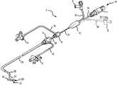
- FIG. 1is an isometric view of a ablation catheter/introducer assembly including an electrode tip according to a generic embodiment of the present invention.
- FIG. 2is an elevation view of a distal portion of a catheter, including a virtual electrode tip, according to one embodiment of the present invention.
- FIG. 3is a top plan view of the catheter of FIG. 2 .
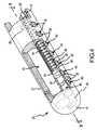
- FIG. 4is an isometric view with a partial cut-away of the distal end of the catheter of FIG. 2 .
- FIG. 5is a cross-section view of the catheter of FIG. 2 taken along line 5 - 5 as indicated in FIG. 4 .
- FIG. 6is a cross-section view of the catheter of FIG. 2 taken along line 6 - 6 as indicated in FIG. 5 .
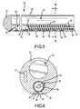
- FIG. 7is an isometric view with a partial cut-away of a second embodiment of a catheter according to the present invention.
- FIG. 8is an isometric view with a partial cut-away of a third embodiment of a catheter according to the present invention.
- FIG. 9is an isometric view of a heart with portions of the atria and ventricles cut-away to reveal positioning of a generic version of the catheter of the present invention in the left atrium, adjacent to the left superior pulmonary vein.
- the present inventionconcerns an improved design for ablation catheters used, for example, in cardiac ablation procedures to produce linear lesions in cardiac tissue.
- the electrode structure on the distal end of the catheter of the present inventionis generally termed a “virtual electrode.”
- ablation energyis primarily imparted to the target tissue via energy transfer through a conductive fluid medium escaping the distal end of the catheter rather than by actual contact of a traditional electrode with the tissue.
- the present inventionis primarily directed to providing a variable length virtual electrode to allow a clinician to create lesions of varying length in the target tissue.
- FIG. 1is an isometric view of a catheter/introducer assembly 2 for use in conjunction with the present invention.
- a catheter 22 with a handle interface 4 at a proximal end 14 and an ablation electrode section 20at a distal end 12 is used in combination with an inner guiding introducer 28 and an outer guiding introducer 26 to facilitate formation of lesions on tissue, for example, cardiovascular tissue.
- the inner guiding introducer 28is longer than and is inserted within the lumen of the outer guiding introducer 26 .
- a single guiding introducer or a precurved transeptal sheathmay be used instead of both the inner guiding introducer 28 and the outer guiding introducer 26 .
- introducers or precurved sheathsare shaped to facilitate placement of the ablation electrode section 20 at the tissue surface to be ablated.
- the outer guiding introducer 26may be formed with a curve at the distal end 12 .
- the inner guiding introducer 28may be formed with a curve at the distal end 12 .
- the curves in the guiding introducers 26 , 28help orient the catheter 22 as it emerges from the inner guiding introducer 26 in a cardiac cavity.
- the inner guiding introducer 28 and the outer guiding introducer 26are used navigate a patient's vasculature to the heart and through its complex physiology to reach specific tissue to be ablated.
- the guiding introducers 26 , 28need not be curved or curved in the manner depicted depending upon the desired application.
- each of the guiding introducers 26 , 28is connected with a hemostatic valve 6 at its proximal end to prevent blood or other fluid that fills the guiding introducers 26 , 28 from leaking before the insertion of the catheter 22 .
- the hemostatic valves 6form tight seals around the shafts of the guiding introducers 26 , 28 or the catheter 22 when inserted therein.
- Each hemostatic valve 6may be have a port connected with a length of tubing 16 to a fluid introduction valve 8 .
- the fluid introduction valves 8may be connected with a fluid source, for example, saline or a drug, to easily introduce the fluid into the introducers, for example, to flush the introducer or to inject a drug in to the patient.
- Each of the fluid introduction valves 8may control the flow of fluid into the hemostatic valves 16 and thereby the guiding introducers 26 , 28 .
- the proximal end 14 of the catheter 22may include a catheter boot 10 that seals around several components to allow the introduction of fluids and control mechanisms into the catheter 22 .
- a catheter boot 10that seals around several components to allow the introduction of fluids and control mechanisms into the catheter 22 .
- at least one fluid introduction valve 8 with an attached length of tubing 16may be coupled with the catheter boot 10 .
- An optional fluid introduction valve 8 ′ and correlative tube 16 ′may also be coupled with the catheter boot 10 , for example, for the introduction of fluid into a catheter with multiple fluid lumens if separate control of the pressure and flow of fluid in the separate lumens is desired.
- a handle interface 4 for connection with a control handle, a generator, and/or sensing equipmentmay be coupled with the catheter boot 10 via a control shaft 24 .
- the control shaft 24may enclose, for example, control wires for manipulating the catheter 22 or ablation electrode section 20 , conductors for energizing an electrode in the ablation electrode section 20 , and/or lead wires for connecting with sensors in the ablation electrode section 20 .
- the catheter boot 10provides a sealed interface to shield the connections between such wires and fluid sources and one or more lumen in the catheter 22 through which they extend.
- the distal end of the cathetermay be straight or take on a myriad of shapes depending upon the desired application.
- the distal end 12 of one embodiment of a catheter 22 according to the present inventionis shown in greater detail in FIGS. 2 and 3 .
- the catheter 22consists mainly of a “straight” section 30 extending from the catheter boot 10 at the proximal end 14 to a point adjacent to the distal end 12 of the catheter/introducer assembly 2 (see the exemplary catheter of FIG. 1 ).
- the catheter 22is composed of a first curved section 32 and a second curved section 34 before transitioning into a third curved section 36 that forms the ablation electrode.
- the first curved section 32is adjacent and distal to the straight section 30 and proximal and adjacent to the second curved section 34 .
- the second curved section 34is itself proximal and adjacent to the third curved section 36 .
- the straight section 30 , first curved section 32 , second curved section 34 , and third curved section 36may together form a single, unitary structure of the catheter 22 , but may originally be separate pieces joined together to form the catheter 22 .
- Each of the different sections of the cathetermay be constructed from a number of different polymers, for example, polypropylene, oriented polypropylene, polyethylene, polyethylene terephthalate, crystallized polyethylene terephthalate, polyester, polyvinyl chloride, polytetraflouroethylene (PTFE), expanded polytetraflouroethylene (ePTFE), and Pellethane.
- the different sections of the cathetermay be composed, for example, of different formulations of Pebax® resins (AUTOFINA Chemicals, Inc., Philadelphia, Pa.), or other polyether-block co-polyamide polymers, which can be used to create desired materials stiffness within the different sections of the catheter.
- Pebax® resinsAUTOFINA Chemicals, Inc., Philadelphia, Pa.
- different mechanical propertiese.g., flexibility or stiffness
- the cathetermay also be a braided catheter wherein the catheter wall includes a cylindrical and/or flat braid of metal fibers (not shown), for example, stainless steel fibers.
- a metallic braidmay be included in the catheter to add stability to the catheter and also to resist radial forces that might crush the catheter.
- Metallic braidalso provides a framework to translate torsional forces imparted by the clinician on the proximal end of the catheter to the distal end to rotate the catheter for appropriate orientation of the ablation electrode.
- the straight section 30is generally the portion of the catheter 22 that remains within the vasculature of the patient while a sensing or ablation procedure is performed by a clinician.
- the ablation electrode section 20may assume a generally circular or C-shaped configuration when deployed from the inner guiding introducer 28 .
- the first curved section 32 and second curved section 34 of the catheter 22align the straight section 30 of the catheter 22 with respect to the third curved section 36 .
- the distal end of the straight section 30 of the catheter 22is oriented in a position where a longitudinal axis extending through the distal end of the straight section 30 passes orthogonally through the center of a circle defined by the C-shaped third curved section 36 .
- the straight section 30 of the catheter 122is spatially displaced from the ablation electrode section 120 so that the straight section 30 is unlikely to interfere with the interface between the ablation electrode on the third curved section 36 and the cardiac tissue as further described below.
- FIGS. 4 , 5 , and 6depict in greater detail the mechanism for creating a variable length ablation electrode 20 according to one embodiment of the present invention.
- the catheter 22defines a fluid lumen 42 that extends the entire length of the catheter 22 from the proximal end 14 at the catheter boot 10 to the ablation electrode section 20 where it is capped by the distal tip 18 of the catheter 22 .
- the distal end 12 of the catheter 22also defines a second lumen in the form of a fluid manifold 46 .
- the fluid manifold 46generally extends only the length of the ablation electrode section 20 of the catheter 22 .
- the fluid lumen 42 and the fluid manifold 46are separated by an interior wall 56 .
- the fluid lumen 42 and the fluid manifold 46are fluidly connected at the proximal end of the fluid manifold 46 via a transverse inlet channel 48 .
- the transverse inlet channel 48communicates fluid, for example, a conductive fluid such as isotonic saline, from the fluid lumen 42 flowing from a fluid source (not shown) at the proximal end 12 of the catheter 22 into the proximal end of the fluid manifold 46 .
- a series of blind holes 40are spaced apart linearly along the length of the ablation electrode section 20 of the catheter 22 adjacent the position of the fluid manifold 46 .
- the blind holes 40only penetrate partially into the exterior wall 58 of the catheter 22 .
- An array of smaller weep holes 38 positioned within each blind hole 40extend through the exterior wall 58 of the catheter 22 into the fluid manifold 46 , thereby providing fluid communication between the fluid manifold 46 and the blind holes 40 .
- the blind holes 40are sized and spaced apart from each other in order to produce a continuous linear lesion.
- the weep holes 38 in each blind hole 40are similarly sized and chosen in number and arrangement to provide an appropriate volume and velocity of conductive fluid flow to create the desired lesion.
- a plug 52resides within the fluid manifold 46 and is fixed to the distal end of an adjustment shaft 50 .
- the adjustment shaft 50may be a wire that extends from the plug 52 proximally through the catheter 22 and ultimately through the control shaft 24 for manipulation via a handle control (not shown) attached to the handle interface 4 .
- the adjustment shaft 50is sized to enable to it to travel the length of the fluid manifold 46 .
- the proximal end of the fluid manifold 46creates a fluid seal around the outer surface of the adjustment shaft 50 , thereby preventing fluid within the fluid manifold 46 from traveling proximally through the catheter 22 along the length of the adjustment shaft 50 .
- the plug 52is affixed to the distal end of the adjustment shaft 50 .
- the perimeter shape of the plug 52is the same as the cross-sectional shape of the interior wall defining the fluid manifold 46 . In this manner, the plug 52 creates a fluid-tight seal as it interfaces with the interior wall of the fluid manifold 46 .
- the plug 52is cylindrical in shape as is the interior wall of the fluid manifold 46 .
- the diameter of the plug 52is thus the same as the diameter across the interior wall of the fluid manifold 46 .
- the plug 52While a fluid seal is created between the plug 52 and the interior wall of the fluid manifold 46 , the plug 52 is not affixed against the fluid manifold 46 and is able to travel the entire length of the fluid manifold 46 under the operation of the adjustment shaft 50 .
- the plugmay be formed of or coated with a layer of Teflon® to provide the desired movable sealing capabilities.
- a spring electrode 54is also housed within the fluid manifold 46 .
- the spring electrode 54may be in the shape of a coil and is attached at a first end to the proximal side of the plug 52 and is fixed at a second end to the proximal end wall of the fluid manifold 46 .
- the spring electrode 54is also coupled with an electrode lead wire 44 , which extends proximally through the catheter 22 to the handle interface 4 for ultimate connection with a power source (not shown).
- the distal end of the adjustment shaft 52is positioned within the coil windings of the spring electrode 54 .
- the spring electrode 54is designed to resist compression and is sized to extend the entire length of the fluid manifold 46 .
- the spring electrode 54In a relaxed state, the spring electrode 54 extends the entire length of the fluid manifold 46 pushing the plug 52 against the distal end wall of the fluid manifold 46 wherein the spring electrode 54 maintains a mild compressive force. In response to appropriate user control of the adjustment shaft 50 , the length of the spring electrode 54 may be manipulated. If the adjustment shaft 50 is pulled proximally, the plug 52 imparts a compressive force proximally on the electrode spring 54 . The adjustment shaft 50 in combination with the plug 52 thereby compresses the spring electrode 54 and thus allows the plug 52 to travel proximally within the fluid manifold 46 .
- the spring electrode 54is at rest in an extended position, thus pushing the plug 52 against the distal end of the fluid manifold 46 . It should be noted that in addition to the force of the spring electrode 54 , pressure of the conductive fluid in the fluid manifold 46 also forces the plug 52 toward the distal end of the fluid manifold 46 . With the plug 52 in this distal position, the conductive fluid entering the fluid manifold 46 from the fluid lumen 42 via the transverse inlet channel 48 fills the entire length of the fluid manifold 46 . Upon application of energy transmitted along the electrode lead wire 44 from an energy source, the spring electrode 54 is energized and transfers energy to the conductive fluid throughout the fluid manifold 46 .
- the conductive fluid in the fluid manifold 46is under pressure and thus is forced to exit the fluid manifold 46 through the weep holes 38 in the exterior wall 58 of the catheter 22 .
- the conductive fluid exiting the weep holes 38spreads laterally within the area of the recessed blind holes 40 , even when the ablation electrode section 20 is placed directly against the target tissue to be ablated. This allows for greater surface area contact of the tissue by the energized conductive fluid exiting the catheter 22 resulting in a more even lesion.
- each of the weep holes 38 and blind holes 40is in fluid communication with the conductive fluid within the fluid manifold 46 .
- ablation energyis transmitted to adjacent tissue along the entire length of the ablation electrode section 20 of catheter 22 .
- the clinicianmay actuate the adjustment shaft 50 by pulling it proximally. Proximal movement of the adjustment shaft 50 in turn pulls the plug 52 proximally, which simultaneously compresses the spring electrode 54 .
- the conductive fluid within the fluid manifold 46cannot flow distally beyond the plug 52 .
- those weep holes 38 and blind holes 40 distal to the position of the plug 52are no longer part of an active electrode array.
- the active length of the ablation electrode section 20 of the catheter 22can be variably adjusted by the clinician.
- a vacuummay be created in the area of the fluid manifold 46 distal to the distal end of the plug 52 .
- bloodmay enter into the fluid manifold 46 via the weep holes 38 distal to the plug 52 at that particular time.
- This entry of blood into the catheter 22is not considered of significant concern for at least two reasons. First, there is little likelihood of coagulum forming within the weep holes 38 or the area of the fluid manifold 46 distal to the plug 52 because the plug 52 insulates the blood from the ablation energy conducted by the spring electrode 54 on the proximal side of the plug 52 .
- the plug 52forces the blood within the fluid manifold 46 distal to the plug 52 out of the fluid manifold 46 through weep holes 38 of the blind holes 40 distal to the plug 52 . Further, once the plug 52 moves distally past a particular blind hole 40 , the fluid within the fluid manifold 46 on the proximal side of the plug 52 forces any remaining blood within the weep holes 38 through the exterior wall 58 of the catheter 22 . It may be desirable, when moving the adjustment shaft 50 distally, to cease the application of ablation energy through the electrode lead wire 44 and spring electrode 54 for a period of time in order to appropriately flush and cleanse the fluid manifold 46 as necessary.
- the catheter 22may further house a shape-retention or shape-memory wire 43 in order to impart a desired shape to the distal end 12 of the catheter 22 in the area of the ablation electrode section 20 . See FIGS. 4 and 6 .
- a shape-retention or shape-memory wire 43is flexible while a clinician negotiates the catheter 122 through the vasculature to reach the heart and enter an atrial chamber.
- the shape-retention/shape-memory wire 43can be caused to assume a pre-formed shape form, e.g., the C-shaped configuration of the ablation electrode section 20 , to accurately orient the ablation electrode section 20 within the cardiac cavity for the procedure to be performed.
- the C-shaped configuration of the ablation electrode section 20may be used to perform ablation operations at the ostia of vessels entering the atria.
- any desired shapemay be imparted to the catheter through the use of such shape-retention or shape-memory wires to appropriately conform to tissue or to the shape of a cavity in order to create the desired lesion at a desired location.
- the shape-retention/shape-memory wire 43may be NiTinol wire, a nickel-titanium (NiTi) alloy, chosen for its exceptional shape-memory properties.
- Shape-memory metalssuch as NiTinol, are materials that have been plastically deformed to a desired shape before use. Then upon heat application, either from the body as the catheter is inserted into the vasculature or from external sources, the shape-memory material is caused to assume its original shape before being plastically deformed.
- a shape-memory wiregenerally exhibits increased tensile strength once the transformation to the pre-formed shape is completed.
- NiTinol and other shape-memory alloysare able to undergo a “martenistic” phase transformation that enables them to change from a “temporary” shape to a “parent” shape at temperatures above a transition temperature. Below the transition temperature, the alloy can be bent into various shapes. Holding a sample in position in a particular parent shape while heating it to a high temperature programs the alloy to remember the parent shape. Upon cooling, the alloy adopts any temporary shape imparted to it, but when heated again above the transition temperature, the alloy automatically reverts to its parent shape.
- shape-memory materialsmay also be super elastic—able to sustain a large deformation at a constant temperature—and when the deforming force is released they return to their original undeformed shape.
- NiTinolhave transformation temperatures ranging between ⁇ 100 and +110° C., have great shape-memory strain, are thermally stable, and have excellent corrosion resistance, which make NiTinol exemplary for use in medical devices for insertion into a patient.
- the shape-memory wiremay be designed using NiTinol with a transition temperature around or below room temperature. Before use the catheter is stored in a low-temperature state. By flushing the fluid lumen with chilled saline solution, the NiTinol shape-memory wire can be kept in the deformed state while positioning the catheter at the desired site.
- the flow of chilled saline solutioncan be stopped and the catheter, either warmed by body heat or by the introduction of warm saline, promotes recovery by the shape-memory wire to assume its “preprogrammed” shape, forming, for example, the C-shaped curve of the ablation electrode section.
- FIG. 7A second embodiment of the ablation electrode structure 120 according to the present invention is depicted in FIG. 7 .
- the catheter 122defines a fluid lumen 142 extending the length of the catheter 122 from the proximal end to the distal tip 118 .
- a fluid manifold 146extends within the ablation electrode section 120 at the distal end of the catheter 122 parallel with the fluid lumen 142 and is separated from the fluid lumen 142 by an interior wall 156 .
- the fluid manifold 146is in fluid communication with the fluid lumen 142 via the transverse inlet channel 148 extending between the fluid manifold 146 and the fluid lumen 142 through the interior wall 156 .
- the transverse inlet channel 148is located at the proximal end of the fluid manifold 146 .
- a linear array of blind holes 140is formed within the exterior wall 158 of the catheter 122 opposite the side of the fluid lumen 142 . Within each blind hole 140 is a collection of weep holes 138 , which extend through the exterior wall 158 of the catheter 122 and which are in fluid communication with the fluid manifold 146 .
- a spring electrode 154resides within the fluid manifold 146 and is connected to an energy source at a proximal end of the catheter 122 via an electrode lead wire 144 .
- the proximal end of the spring electrode 154is fixed to the catheter 122 at the proximal end of the fluid manifold 146 .
- the distal end of the spring electrode 154is affixed to a plug 152 .
- the plug 152is sized to seal against the internal walls of the fluid manifold 146 , thereby preventing any of the conductive fluid entering the proximal end of the fluid manifold 146 from the fluid lumen 142 via the transverse inlet channel 148 from seeping or flowing distally past the plug 152 .
- a first pull wire 160is fixed to the proximal side of the plug 152 and extends distally therefrom through the coils of the spring electrode 154 to exit the proximal end of the fluid manifold 146 and travel distally through the catheter 122 to the handle interface for manipulation by a clinician.
- a second pull wire 162similarly extends proximally through the catheter 122 parallel to the first pull wire 160 and is received in the handle interface for ultimate manipulation by a clinician. The second pull wire 162 extends distally within the fluid manifold 146 and through the interior of the windings of the spring electrode 154 .
- the second pull wire 162extends through an aperture within the plug 152 , wraps around a pulley 150 seated at the distal end of the fluid manifold 146 at the distal tip 118 of the catheter 122 , and returns proximally to where it is affixed to the distal side of the plug 152 .
- the interface between the plug 152 and the second pull wire 162is designed to create a fluid seal between the plug 152 and the second pull wire 162 while simultaneously allowing the plug 152 to move along the second pull wire 162 .
- a fluid sealis also created about the first pull wire 160 and the second pull wire 162 at the proximal end of the fluid manifold 146 where the first pull wire 160 and the second pull wire 162 exit the fluid manifold 166 into a proximal portion of the catheter 122 .
- a cliniciancan vary the length of an active portion of the ablation electrode section 120 of the catheter 122 by pulling either the first pull wire 160 or the second pull wire 162 proximally.
- the plug 152moves proximally within the fluid manifold 146 , thus preventing flow of conductive fluid through any of the weep holes 138 located distal to the position of the plug 152 .
- the effective length of the ablation electrode section 120is shortened from the maximum allowed by the design of the ablation electrode section 120 .
- an ablation electrode section of a catheter of the present inventionwere to have an array of ten blind holes and the plug were positioned proximal to two of the blind holes, only eight of the blind holes would be able to direct energized conductive fluid exiting from the corresponding weep holes to adjacent tissue for ablation.
- the second pull wire 162may be pulled proximally by the clinician.
- the pulling force on the second pull wire 162pulls on the distal end of the plug 152 as a result of the transference of the proximal pulling force to a distal pulling force as the second pull wire 162 wraps around the pulley 150 .
- the plug 152moves proximally and distally within the fluid manifold 146 , it also slides along a length of the second pull wire 162 within the fluid manifold 146 .
- the ablation electrode section of the cathetermay be designed without a spring electrode.
- the first pull wire 160may also perform the function of an active electrode to transfer energy from an energy source to the conductive fluid within the fluid manifold 146 . Without an expansive spring force acting on the plug, the need for the combination of a first pull wire, a second pull, and a pulley in order to move the plug within the fluid lumen becomes apparent.
- FIG. 8A further embodiment of the present invention is depicted in FIG. 8 .
- a catheter 222has an ablation electrode section 220 adjacent to the distal tip 218 of the catheter 222 .
- a fluid lumen 242extends from the proximal end of the catheter 222 to the distal tip 218 .
- Adjacent the fluid lumen 242 within the catheter 222is a fluid manifold 246 .
- the fluid manifold 246is a lumen of discrete length extending only within the ablation electrode section 220 of the catheter 222 .
- the fluid manifold 246is in fluid communication with the fluid lumen 242 via a transverse inlet channel 248 defined within an interior wall 256 separating the fluid lumen 242 from the fluid manifold 246 .
- the transverse inlet channel 248is located adjacent the distal tip 218 of catheter 222 .
- the fluid manifold 246is positioned adjacent to the exterior wall 258 of the catheter 222 .
- a linear array of blind holes 240are formed within the exterior wall 258 of the catheter 222 adjacent the fluid manifold 246 .
- Within each blind hold 240is a set of weep holes 238 , which extend through the exterior wall 258 of the catheter 222 .
- three weep holes 238are provided per blind hole 240 .
- any number of weep holesfor example, between one and ten, may be provided per blind hole.
- the determination of a number of weep holes per blind holemay be made based upon, for example, a desired rate of fluid flow exiting the catheter or a desired fluid pressure or velocity of the fluid flow through the weep holes.
- a plug 252is affixed to the distal end of an adjustment shaft 250 and is positioned within the fluid manifold 246 .
- the adjustment shaft 250extends proximally through the catheter 222 to the handle interface for manipulation by a clinician.
- the circumferential wall of the plug 252seals against the interior wall of the fluid manifold 246 to prevent fluid migration proximal to the plug 252 .
- a spring electrode 254is positioned within the fluid manifold 246 and extends from the distal tip 218 of the catheter 222 to the distal face 260 of the plug 252 .
- the spring electrode 254is fixed at its distal end to the distal end of the fluid manifold 246 and at its proximal end to the distal end of the plug 252 .
- the adjustment shaft 250acts as an electrode lead wire to transfer ablation energy from an energy source to the spring electrode 254 .
- the plug 252is conductive and is thus both mechanically and electrically coupled with the adjustment shaft 250 .
- the adjustment shaft 250 and the proximal side in the side walls of the plug 252are covered with an insulating coating 262 .
- the distal face 260 of the plug 252remains uncoated and is electrically coupled with the spring electrode 254 .
- each of the blind holes 240 of the ablation electrode section 220 of the catheter 222may operate as an active virtual electrode to flow energized conductive fluid against adjacent tissue to be ablated.
- Conductive fluidflows through the fluid lumen 242 , through the transverse inlet channel 248 adjacent the distal tip 218 of the catheter 222 , into the fluid manifold 246 where ablation energy is transferred from the spring electrode 254 to the conductive fluid, and exits the fluid manifold 246 via the weep holes 238 at the location of each of the blind holes 240 .
- a clinicianmay push the adjustment shaft 250 distally thus moving the plug 252 distally and compressing the spring electrode 254 .
- the plug 252As the plug 252 is moved distally, it arrests the flow of fluid to that portion of the fluid manifold 246 proximal to the plug 252 .
- any blind hole 240 and its corresponding weep holes 238 positioned proximal to the position of the plug 252is isolated from the supply of conductive fluid entering the fluid manifold 246 through the transverse inlet channel 248 at the distal end of the fluid manifold 246 .
- the effective length of the active portion of the ablation electrode section 220is shortened. The difference between the present embodiment of FIG.
- the active portion of the ablation electrode section 220 of the present embodimentis located adjacent the distal tip 218 of the catheter 222 .
- the active portion of ablation section of the catheteris spaced apart from the distal tip of the catheter when the ablation electrode section is shortened from its maximum possible length.
- portion of the adjustment shaft 250 extending within the fluid manifold 246 and the proximal side and sidewalls of the plug 252are coated with electrically insulating material. It is desirable to insulate the adjustment shaft 50 and the proximal side of the plug 252 to ensure that ablation energy is not imparted to any blood that may enter into the fluid manifold 246 on the proximal side of the plug 252 when plug 252 is positioned apart from the proximal end of the fluid manifold 246 .
- the spring electrodemay be positioned proximal to the plug and affixed to the plug at its distal end.
- the adjustment shaftmay extend within the coils of the spring electrode within the fluid manifold to attach to the proximal side of the plug.
- the spring electrode in this embodimentmay exert a contractile force to pull the plug proximally after having been moved distally by the adjustment shaft Alternatively, the spring may not be an electrode and may merely provide the mechanical, contractile force. In this version, the adjustment shaft may function as the electrode.
- the plugWhen the spring is in a contracted, resting position, the plug may be located adjacent to and block the transverse inlet channel, thus preventing fluid flow from the fluid lumen into the fluid manifold. Either of these embodiments may be desirable as a mechanism to prevent fluid flow through fluid manifold and out the weep holes except when an ablation procedure is actually performed in order to reduce the volume of conductive fluid introduced into the patient.
- the fluid manifolddoes not house a spring electrode.
- the plugis merely moved proximally and distally within the fluid manifold by the adjustment shaft.
- the adjustment shaftmay be affixed to the proximal side of the plug and the transverse inlet channel may be located at either the proximal end or the distal end of the fluid manifold. If the transverse inlet channel is at the proximal end of the fluid manifold, the adjustment shaft may operate as the electrode. If the transverse inlet channel is located at the distal end of the fluid manifold, an expandable electrode positioned distal to the plug may be desirable.
- One possible design for such and expandable electrodeis to provide a hollow adjustment shaft that houses the electrode wire.
- the electrode wirewould extend through and aperture in the plug to the distal end of the fluid manifold. Both the plug and the adjustment shaft would travel along the electrode wire, variously exposing and concealing the wire as the plug is moved proximally and distally. Again, it is desirable to not have an active electrode wire exposed within the fluid manifold on a side of the plug opposite the volume of conductive fluid to avoid energizing any blood that may enter the fluid manifold and unnecessarily create coagulum.
- FIG. 9schematically depicts the catheter 22 and ablation electrode section 20 according to a generic embodiment of the present invention being used to ablate tissue in a left superior pulmonary vein 70 .
- FIG. 9includes a number of primary components of the heart 60 to orient the reader. In particular, starting in the upper left-hand portion of FIG.
- the superior vena cava 72the right atrium 74 , the inferior vena cava 76 , the right ventricle 78 , the left ventricle 80 , the left inferior pulmonary vein 82 , left superior pulmonary vein 70 , the left atrium 84 , the right superior pulmonary vein 86 , the right inferior pulmonary vein 88 , the left pulmonary artery 66 , the arch of the aorta 64 , and the right pulmonary artery 68 .
- the distal end of the ablation electrode section 20is positioned adjacent to the ostium 90 of the left superior pulmonary vein 70 using known procedures.
- the right venous systemmay be first accessed using the “Seldinger technique.”
- a peripheral veinsuch as a femoral vein
- the puncture woundis dilated with a dilator to a size sufficient to accommodate an introducer (e.g., the outer guiding introducer 26 shown in FIG. 1 ).
- the outer guiding introducer 26 with at least one hemostatic valveis seated within the dilated puncture wound while maintaining relative hemostasis.
- the outer guiding introducer 26is advanced along the peripheral vein, into the inferior vena cava 76 , and into the right atrium 74 .
- a transeptal sheathmay be further advanced through the outer guiding introducer 26 to create a hole in the interatrial septum between the right atrium 74 and the left atrium 84 .
- the inner guiding introducer 28housing the catheter 22 with the ablation electrode section 20 on the distal end, is introduced through the hemostatic valve 6 of the outer guiding introducer 26 and navigated into the right atrium 74 , through the hole in the interatrial septum, and into the left atrium 84 .
- the ablation electrode section 20 of the catheter 22and may be advanced through the distal tip of the inner guiding introducer 28 .
- the ablation electrode section 20 as shown in FIG. 19is being inserted into the ostium 90 of the left superior pulmonary vein 70 to contact the tissue of the walls of the vein.
- the configuration of the ablation electrode section 20 as depicted in FIGS. 2 and 3is advantageous for maintaining consistent contact with tissue in a generally cylindrical vessel. Other configurations of the ablation electrode section 20 may be used to greater advantage on tissue surfaces of other shapes.
- the ablation electrode section 20may be energized to create the desired lesion in the left superior pulmonary vein 70 .
- the RF energy emanating from the ablation electrode section 20is transmitted through the conductive fluid medium, which flows through the fluid lumen, through the dispersion openings, through the porous material (depending upon the particular embodiment), through the mesh layer, and impacts the adjacent tissue.
- the conductive fluid mediummay also experience ohmic heating as it flows along either the electrode lead or through the mesh layer acting as the electrode (depending upon the particular embodiment).
- Lesion formationmay thus also be facilitated by the conductive fluid medium, which may have been heated by ohmic heating to a sufficiently high temperature to facilitate or enhance lesion formation.
- the RF energyis conducted into the adjacent tissue and the heated conductive fluid convectively affects the temperature of the tissue.
- sufficient RF energymust be supplied to the electrode to produce this lesion-forming temperature in the adjacent tissue for the desired duration.
- the length of the lesion formedmay be varied by varying the active length of the ablation electrode section 20 of the catheter 22 .
- the clinicianmay adjust the position of the plug within the fluid manifold to prevent the egress of energized conductive fluid from the blind holes positioned opposite the plug from the inlet of the conductive fluid into the fluid manifold. In this manner, only those blind holes positioned between the plug and the transverse inlet channel will act as an outlet for the energized conductive fluid for ablation of adjacent tissue. In this manner the length of the lesion on the target tissue may be adjusted according to the clinical need without unnecessary tissue necrosis.
- connection referencese.g., attached, coupled, connected, and joined are to be construed broadly and may include intermediate members between a collection of elements and relative movement between elements unless otherwise indicated. As such, connection references do not necessarily infer that two elements are directly connected and in fixed relation to each other. It is intended that all matter contained in the above description or shown in the accompanying drawings shall be interpreted as illustrative only and not limiting. Changes in detail or structure may be made without departing from the basic elements of the invention as defined in the following claims.
Landscapes
- Health & Medical Sciences (AREA)
- Life Sciences & Earth Sciences (AREA)
- Surgery (AREA)
- Engineering & Computer Science (AREA)
- Plasma & Fusion (AREA)
- Medical Informatics (AREA)
- Otolaryngology (AREA)
- Physics & Mathematics (AREA)
- Cardiology (AREA)
- Biomedical Technology (AREA)
- Heart & Thoracic Surgery (AREA)
- Nuclear Medicine, Radiotherapy & Molecular Imaging (AREA)
- Molecular Biology (AREA)
- Animal Behavior & Ethology (AREA)
- General Health & Medical Sciences (AREA)
- Public Health (AREA)
- Veterinary Medicine (AREA)
- Surgical Instruments (AREA)
- Media Introduction/Drainage Providing Device (AREA)
Abstract
Description
Claims (20)
Priority Applications (2)
| Application Number | Priority Date | Filing Date | Title |
|---|---|---|---|
| US11/154,098US7776034B2 (en) | 2005-06-15 | 2005-06-15 | Ablation catheter with adjustable virtual electrode |
| PCT/US2006/023306WO2006138462A2 (en) | 2005-06-15 | 2006-06-15 | Ablation catheter with adjustable virtual electrode |
Applications Claiming Priority (1)
| Application Number | Priority Date | Filing Date | Title |
|---|---|---|---|
| US11/154,098US7776034B2 (en) | 2005-06-15 | 2005-06-15 | Ablation catheter with adjustable virtual electrode |
Publications (2)
| Publication Number | Publication Date |
|---|---|
| US20070005051A1 US20070005051A1 (en) | 2007-01-04 |
| US7776034B2true US7776034B2 (en) | 2010-08-17 |
Family
ID=37571163
Family Applications (1)
| Application Number | Title | Priority Date | Filing Date |
|---|---|---|---|
| US11/154,098Expired - Fee RelatedUS7776034B2 (en) | 2005-06-15 | 2005-06-15 | Ablation catheter with adjustable virtual electrode |
Country Status (2)
| Country | Link |
|---|---|
| US (1) | US7776034B2 (en) |
| WO (1) | WO2006138462A2 (en) |
Cited By (42)
| Publication number | Priority date | Publication date | Assignee | Title |
|---|---|---|---|---|
| US20090306655A1 (en)* | 2008-06-09 | 2009-12-10 | Stangenes Todd R | Catheter assembly with front-loaded tip and multi-contact connector |
| US20090306651A1 (en)* | 2008-06-09 | 2009-12-10 | Clint Schneider | Catheter assembly with front-loaded tip |
| US20100042095A1 (en)* | 2008-08-13 | 2010-02-18 | Robert Bigley | Systems and methods for screen electrode securement |
| US8317786B2 (en) | 2009-09-25 | 2012-11-27 | AthroCare Corporation | System, method and apparatus for electrosurgical instrument with movable suction sheath |
| WO2012173673A1 (en)* | 2011-06-16 | 2012-12-20 | St. Jude Medical, Atrial Fibrillation Division, Inc. | Irrigant distribution system for flexible electrodes |
| US8346339B2 (en) | 2011-04-22 | 2013-01-01 | Topera, Inc. | Basket style cardiac mapping catheter having a flexible electrode assembly for detection of cardiac rhythm disorders |
| US8355799B2 (en) | 2008-12-12 | 2013-01-15 | Arthrocare Corporation | Systems and methods for limiting joint temperature |
| US8663216B2 (en) | 1998-08-11 | 2014-03-04 | Paul O. Davison | Instrument for electrosurgical tissue treatment |
| US8696659B2 (en) | 2010-04-30 | 2014-04-15 | Arthrocare Corporation | Electrosurgical system and method having enhanced temperature measurement |
| US8979840B2 (en) | 2010-12-17 | 2015-03-17 | St. Jude Medical, Atrial Fibrillation Division, Inc. | Irrigant distribution system for flexible electrodes |
| US8998890B2 (en) | 2005-12-06 | 2015-04-07 | St. Jude Medical, Atrial Fibrillation Division, Inc. | Assessment of electrode coupling for tissue ablation |
| US9066725B2 (en) | 2012-12-06 | 2015-06-30 | St. Jude Medical, Atrial Fibrillation Division, Inc. | Irrigant distribution system for electrodes |
| US9173586B2 (en) | 2005-12-06 | 2015-11-03 | St. Jude Medical, Atrial Fibrillation Division, Inc. | System and method for assessing coupling between an electrode and tissue |
| US9204927B2 (en) | 2009-05-13 | 2015-12-08 | St. Jude Medical, Atrial Fibrillation Division, Inc. | System and method for presenting information representative of lesion formation in tissue during an ablation procedure |
| US9254163B2 (en) | 2005-12-06 | 2016-02-09 | St. Jude Medical, Atrial Fibrillation Division, Inc. | Assessment of electrode coupling for tissue ablation |
| US9271782B2 (en) | 2005-12-06 | 2016-03-01 | St. Jude Medical, Atrial Fibrillation Division, Inc. | Assessment of electrode coupling of tissue ablation |
| US9339325B2 (en) | 2005-12-06 | 2016-05-17 | St. Jude Medical, Atrial Fibrillation Division, Inc. | System and method for assessing lesions in tissue |
| US9597142B2 (en) | 2014-07-24 | 2017-03-21 | Arthrocare Corporation | Method and system related to electrosurgical procedures |
| US9610119B2 (en) | 2005-12-06 | 2017-04-04 | St. Jude Medical, Atrial Fibrillation Division, Inc. | System and method for assessing the formation of a lesion in tissue |
| US9649148B2 (en) | 2014-07-24 | 2017-05-16 | Arthrocare Corporation | Electrosurgical system and method having enhanced arc prevention |
| US9788891B2 (en) | 2010-12-28 | 2017-10-17 | St. Jude Medical, Atrial Fibrillation Division, Inc. | Ablation electrode assemblies and methods for using same |
| US9839472B2 (en) | 2015-10-29 | 2017-12-12 | Innoblative Designs, Inc. | Screen sphere tissue ablation devices and methods |
| US9855098B2 (en) | 2015-04-29 | 2018-01-02 | Innoblative Designs, Inc. | Cavitary tissue ablation |
| US9855094B2 (en) | 2010-12-28 | 2018-01-02 | St. Jude Medical, Atrial Fibrillation Division, Inc. | Multi-rate fluid flow and variable power delivery for ablation electrode assemblies used in catheter ablation procedures |
| US9993178B2 (en) | 2016-03-15 | 2018-06-12 | Epix Therapeutics, Inc. | Methods of determining catheter orientation |
| US10022183B2 (en) | 2014-04-01 | 2018-07-17 | Innovations In Medicine, Llc | Temperature-responsive irrigated ablation electrode with reduced coolant flow and related methods for making and using |
| US10070921B2 (en) | 2016-10-17 | 2018-09-11 | Innoblative Designs, Inc. | Treatment devices and methods |
| US10076384B2 (en) | 2013-03-08 | 2018-09-18 | Symple Surgical, Inc. | Balloon catheter apparatus with microwave emitter |
| US10166062B2 (en) | 2014-11-19 | 2019-01-01 | Epix Therapeutics, Inc. | High-resolution mapping of tissue with pacing |
| US10201388B2 (en) | 2005-12-06 | 2019-02-12 | St. Jude Medical, Atrial Fibrillation Division, Inc. | Graphical user interface for real-time RF lesion depth display |
| US10231779B2 (en) | 2014-11-19 | 2019-03-19 | Epix Therapeutics, Inc. | Ablation catheter with high-resolution electrode assembly |
| US10362959B2 (en) | 2005-12-06 | 2019-07-30 | St. Jude Medical, Atrial Fibrillation Division, Inc. | System and method for assessing the proximity of an electrode to tissue in a body |
| US10555685B2 (en) | 2007-12-28 | 2020-02-11 | St. Jude Medical, Atrial Fibrillation Division, Inc. | Method and apparatus for determining tissue morphology based on phase angle |
| US10675081B2 (en) | 2015-03-25 | 2020-06-09 | Epix Therapeutics, Inc. | Contact sensing systems and methods |
| US10864039B2 (en) | 2016-02-02 | 2020-12-15 | Innoblative Designs, Inc. | Cavitary tissue ablation system |
| US10869714B2 (en) | 2016-03-01 | 2020-12-22 | Innoblative Designs, Inc. | Resecting and coagulating tissue |
| US10888373B2 (en) | 2017-04-27 | 2021-01-12 | Epix Therapeutics, Inc. | Contact assessment between an ablation catheter and tissue |
| US10912602B2 (en) | 2016-11-08 | 2021-02-09 | Innoblative Designs, Inc. | Electrosurgical tissue and vessel sealing device |
| US20210059747A1 (en)* | 2019-08-29 | 2021-03-04 | St. Jude Medical, Cardiology Division, Inc. | Force sensing catheter including sealed electrode tip assembly and methods of assembling same |
| US11786297B2 (en) | 2017-07-26 | 2023-10-17 | Innoblative Designs, Inc. | Minimally invasive articulating assembly having ablation capabilities |
| US12207863B2 (en) | 2015-10-29 | 2025-01-28 | Innoblative Designs, Inc. | Screen sphere tissue ablation devices and methods |
| US12274490B2 (en) | 2010-12-17 | 2025-04-15 | St. Jude Medical, Atrial Fibrillation Division, Inc. | Irrigated ablation electrode assemblies |
Families Citing this family (25)
| Publication number | Priority date | Publication date | Assignee | Title |
|---|---|---|---|---|
| EP1647232B1 (en) | 2001-12-03 | 2011-08-17 | Ekos Corporation | Catheter with multiple ultrasound radiating members |
| US6893442B2 (en) | 2002-06-14 | 2005-05-17 | Ablatrics, Inc. | Vacuum coagulation probe for atrial fibrillation treatment |
| US7572257B2 (en)* | 2002-06-14 | 2009-08-11 | Ncontact Surgical, Inc. | Vacuum coagulation and dissection probes |
| US8235990B2 (en) | 2002-06-14 | 2012-08-07 | Ncontact Surgical, Inc. | Vacuum coagulation probes |
| US7063698B2 (en) | 2002-06-14 | 2006-06-20 | Ncontact Surgical, Inc. | Vacuum coagulation probes |
| US9439714B2 (en)* | 2003-04-29 | 2016-09-13 | Atricure, Inc. | Vacuum coagulation probes |
| US7789877B2 (en) | 2003-07-02 | 2010-09-07 | St. Jude Medical, Atrial Fibrillation Division, Inc. | Ablation catheter electrode arrangement |
| EP2015846A2 (en) | 2006-04-24 | 2009-01-21 | Ekos Corporation | Ultrasound therapy system |
| JP5054116B2 (en)* | 2006-11-09 | 2012-10-24 | エヌコンタクト サージカル, インコーポレイテッド | Vacuum coagulation probe |
| US20080161799A1 (en)* | 2006-12-29 | 2008-07-03 | Todd Stangenes | Position independent catheter |
| US10182833B2 (en) | 2007-01-08 | 2019-01-22 | Ekos Corporation | Power parameters for ultrasonic catheter |
| EP2170181B1 (en) | 2007-06-22 | 2014-04-16 | Ekos Corporation | Method and apparatus for treatment of intracranial hemorrhages |
| US8864728B2 (en)* | 2008-12-31 | 2014-10-21 | Kci Licensing, Inc. | Multi-conduit manifolds, systems, and methods for applying reduced pressure to a subcutaneous tissue site |
| MX2011006993A (en)* | 2008-12-31 | 2011-08-04 | Kci Licensing Inc | Sleeves, manifolds, systems, and methods for applying reduced pressure to a subcutaneous tissue site. |
| US8323279B2 (en)* | 2009-09-25 | 2012-12-04 | Arthocare Corporation | System, method and apparatus for electrosurgical instrument with movable fluid delivery sheath |
| JP5779931B2 (en)* | 2011-03-24 | 2015-09-16 | 富士通株式会社 | Manufacturing method of semiconductor device |
| WO2013142906A1 (en)* | 2012-03-27 | 2013-10-03 | Cathrx Ltd | An ablation catheter |
| US20130304051A1 (en)* | 2012-05-08 | 2013-11-14 | Greatbatch Ltd. | Transseptal needle apparatus |
| US9358039B2 (en) | 2012-05-08 | 2016-06-07 | Greatbatch Ltd. | Transseptal needle apparatus |
| US8986264B2 (en) | 2012-05-08 | 2015-03-24 | Greatbatch Ltd. | Transseptal needle apparatus |
| US8986300B2 (en)* | 2012-06-25 | 2015-03-24 | Biosense Webster (Israel) Ltd. | Irrigated electrodes with enhanced heat conduction |
| US9370311B2 (en) | 2012-08-17 | 2016-06-21 | Medtronic Ablation Frontiers Llc | Electrophysiology catheter design |
| US9848943B2 (en)* | 2014-04-18 | 2017-12-26 | Biosense Webster (Israel) Ltd. | Ablation catheter with dedicated fluid paths and needle centering insert |
| CN107708581B (en) | 2015-06-10 | 2021-11-19 | Ekos公司 | Ultrasonic wave guide tube |
| CN112998838B (en)* | 2019-12-19 | 2025-06-27 | 杭州德诺电生理医疗科技有限公司 | Occlusion ablation device |
Citations (56)
| Publication number | Priority date | Publication date | Assignee | Title |
|---|---|---|---|---|
| US3911902A (en)* | 1972-09-08 | 1975-10-14 | Nat Res Dev | Catheter pressure transducer |
| US4329994A (en)* | 1980-06-18 | 1982-05-18 | American Hospital Supply Corporation | Multilumen catheter |
| US4407304A (en)* | 1980-06-18 | 1983-10-04 | American Hospital Supply Corporation | Method of mounting an electrical lead in a catheter body |
| US4945912A (en) | 1988-11-25 | 1990-08-07 | Sensor Electronics, Inc. | Catheter with radiofrequency heating applicator |
| US5281217A (en)* | 1992-04-13 | 1994-01-25 | Ep Technologies, Inc. | Steerable antenna systems for cardiac ablation that minimize tissue damage and blood coagulation due to conductive heating patterns |
| US5281213A (en) | 1992-04-16 | 1994-01-25 | Implemed, Inc. | Catheter for ice mapping and ablation |
| US5334193A (en) | 1992-11-13 | 1994-08-02 | American Cardiac Ablation Co., Inc. | Fluid cooled ablation catheter |
| US5431649A (en) | 1993-08-27 | 1995-07-11 | Medtronic, Inc. | Method and apparatus for R-F ablation |
| US5433708A (en) | 1991-05-17 | 1995-07-18 | Innerdyne, Inc. | Method and device for thermal ablation having improved heat transfer |
| US5542434A (en)* | 1994-10-28 | 1996-08-06 | Intelliwire Inc. | Guide wire with deflectable tip and method |
| US5542928A (en) | 1991-05-17 | 1996-08-06 | Innerdyne, Inc. | Method and device for thermal ablation having improved heat transfer |
| US5584872A (en) | 1992-11-13 | 1996-12-17 | Scimed Life Systems, Inc. | Electrophysiology energy treatment devices and methods of use |
| US5609151A (en) | 1994-09-08 | 1997-03-11 | Medtronic, Inc. | Method for R-F ablation |
| US5658278A (en) | 1992-12-01 | 1997-08-19 | Cardiac Pathways, Inc. | Catheter for RF ablation with cooled electrode and method |
| US5676693A (en) | 1992-11-13 | 1997-10-14 | Scimed Life Systems, Inc. | Electrophysiology device |
| US5785706A (en)* | 1996-11-18 | 1998-07-28 | Daig Corporation | Nonsurgical mapping and treatment of cardiac arrhythmia using a catheter contained within a guiding introducer containing openings |
| US5876398A (en) | 1994-09-08 | 1999-03-02 | Medtronic, Inc. | Method and apparatus for R-F ablation |
| US5895417A (en) | 1996-03-06 | 1999-04-20 | Cardiac Pathways Corporation | Deflectable loop design for a linear lesion ablation apparatus |
| US5913854A (en) | 1997-02-04 | 1999-06-22 | Medtronic, Inc. | Fluid cooled ablation catheter and method for making |
| US5913856A (en) | 1997-05-19 | 1999-06-22 | Irvine Biomedical, Inc. | Catheter system having a porous shaft and fluid irrigation capabilities |
| US5919188A (en)* | 1997-02-04 | 1999-07-06 | Medtronic, Inc. | Linear ablation catheter |
| US5921954A (en)* | 1996-07-10 | 1999-07-13 | Mohr, Jr.; Lawrence G. | Treating aneurysms by applying hardening/softening agents to hardenable/softenable substances |
| US5971968A (en)* | 1999-04-08 | 1999-10-26 | Irvine Biomedical, Inc. | Catheter probe having contrast media delivery means |
| US5997532A (en) | 1997-07-03 | 1999-12-07 | Cardiac Pathways Corporation | Ablation catheter tip with a buffer layer covering the electrode |
| US6010500A (en)* | 1997-07-21 | 2000-01-04 | Cardiac Pathways Corporation | Telescoping apparatus and method for linear lesion ablation |
| US6015407A (en)* | 1996-03-06 | 2000-01-18 | Cardiac Pathways Corporation | Combination linear ablation and cooled tip RF catheters |
| US6032077A (en)* | 1996-03-06 | 2000-02-29 | Cardiac Pathways Corporation | Ablation catheter with electrical coupling via foam drenched with a conductive fluid |
| US6044846A (en)* | 1994-06-24 | 2000-04-04 | Edwards; Stuart D. | Method to treat esophageal sphincters |
| US6063080A (en) | 1996-05-16 | 2000-05-16 | Cordis Webster, Inc. | Linear catheter ablation system |
| US6068653A (en) | 1992-11-13 | 2000-05-30 | Scimed Life Systems, Inc. | Electrophysiology catheter device |
| US6080151A (en)* | 1997-07-21 | 2000-06-27 | Daig Corporation | Ablation catheter |
| US6119041A (en) | 1996-03-06 | 2000-09-12 | Cardiac Pathways Corporation | Apparatus and method for linear lesion ablation |
| US6120476A (en) | 1997-12-01 | 2000-09-19 | Cordis Webster, Inc. | Irrigated tip catheter |
| US6120500A (en)* | 1997-11-12 | 2000-09-19 | Daig Corporation | Rail catheter ablation and mapping system |
| US6132405A (en)* | 1995-10-10 | 2000-10-17 | Gambro Ab | Catheter for peritoneal dialysis |
| US6132426A (en) | 1998-05-05 | 2000-10-17 | Daig Corporation | Temperature and current limited ablation catheter |
| US6171275B1 (en) | 1998-12-03 | 2001-01-09 | Cordis Webster, Inc. | Irrigated split tip electrode catheter |
| US6217576B1 (en) | 1997-05-19 | 2001-04-17 | Irvine Biomedical Inc. | Catheter probe for treating focal atrial fibrillation in pulmonary veins |
| US6219582B1 (en) | 1998-12-30 | 2001-04-17 | Daig Corporation | Temporary atrial cardioversion catheter |
| US6235022B1 (en) | 1996-12-20 | 2001-05-22 | Cardiac Pathways, Inc | RF generator and pump apparatus and system and method for cooled ablation |
| US6235044B1 (en) | 1999-08-04 | 2001-05-22 | Scimed Life Systems, Inc. | Percutaneous catheter and guidewire for filtering during ablation of mycardial or vascular tissue |
| US6238393B1 (en) | 1998-07-07 | 2001-05-29 | Medtronic, Inc. | Method and apparatus for creating a bi-polar virtual electrode used for the ablation of tissue |
| US6241722B1 (en) | 1998-06-17 | 2001-06-05 | Cryogen, Inc. | Cryogenic device, system and method of using same |
| US6409722B1 (en) | 1998-07-07 | 2002-06-25 | Medtronic, Inc. | Apparatus and method for creating, maintaining, and controlling a virtual electrode used for the ablation of tissue |
| US6454766B1 (en) | 2000-05-05 | 2002-09-24 | Scimed Life Systems, Inc. | Microporous electrode structure and method of making the same |
| US6522930B1 (en)* | 1998-05-06 | 2003-02-18 | Atrionix, Inc. | Irrigated ablation device assembly |
| US6607505B1 (en)* | 1996-12-19 | 2003-08-19 | Ep Technologies, Inc. | Catheter distal assembly with pull wires |
| US6702811B2 (en) | 1999-04-05 | 2004-03-09 | Medtronic, Inc. | Ablation catheter assembly with radially decreasing helix and method of use |
| US20040181189A1 (en) | 2001-01-26 | 2004-09-16 | Scimed Life Systems, Inc. | Intravascular occlusion balloon catheter |
| US6858026B2 (en) | 1996-10-22 | 2005-02-22 | Epicor Medical, Inc. | Methods and devices for ablation |
| US20050055019A1 (en) | 2003-09-05 | 2005-03-10 | Medtronic, Inc. | RF ablation catheter including a virtual electrode assembly |
| US6960207B2 (en)* | 2003-01-21 | 2005-11-01 | St Jude Medical, Daig Division, Inc. | Ablation catheter having a virtual electrode comprising portholes and a porous conductor |
| US6984232B2 (en)* | 2003-01-17 | 2006-01-10 | St. Jude Medical, Daig Division, Inc. | Ablation catheter assembly having a virtual electrode comprising portholes |
| US7087053B2 (en)* | 2004-05-27 | 2006-08-08 | St. Jude Medical, Atrial Fibrillation Division, Inc. | Catheter with bifurcated, collapsible tip for sensing and ablating |
| US7101362B2 (en)* | 2003-07-02 | 2006-09-05 | St. Jude Medical, Atrial Fibrillation Division, Inc. | Steerable and shapable catheter employing fluid force |
| US7235070B2 (en)* | 2003-07-02 | 2007-06-26 | St. Jude Medical, Atrial Fibrillation Division, Inc. | Ablation fluid manifold for ablation catheter |
Family Cites Families (1)
| Publication number | Priority date | Publication date | Assignee | Title |
|---|---|---|---|---|
| US569927A (en)* | 1896-10-20 | Pull-rod-bending apparatus |
- 2005
- 2005-06-15USUS11/154,098patent/US7776034B2/ennot_activeExpired - Fee Related
- 2006
- 2006-06-15WOPCT/US2006/023306patent/WO2006138462A2/enactiveApplication Filing
Patent Citations (64)
| Publication number | Priority date | Publication date | Assignee | Title |
|---|---|---|---|---|
| US3911902A (en)* | 1972-09-08 | 1975-10-14 | Nat Res Dev | Catheter pressure transducer |
| US4329994A (en)* | 1980-06-18 | 1982-05-18 | American Hospital Supply Corporation | Multilumen catheter |
| US4407304A (en)* | 1980-06-18 | 1983-10-04 | American Hospital Supply Corporation | Method of mounting an electrical lead in a catheter body |
| US4945912A (en) | 1988-11-25 | 1990-08-07 | Sensor Electronics, Inc. | Catheter with radiofrequency heating applicator |
| US5370644A (en) | 1988-11-25 | 1994-12-06 | Sensor Electronics, Inc. | Radiofrequency ablation catheter |
| US5433708A (en) | 1991-05-17 | 1995-07-18 | Innerdyne, Inc. | Method and device for thermal ablation having improved heat transfer |
| US5542928A (en) | 1991-05-17 | 1996-08-06 | Innerdyne, Inc. | Method and device for thermal ablation having improved heat transfer |
| US5281217A (en)* | 1992-04-13 | 1994-01-25 | Ep Technologies, Inc. | Steerable antenna systems for cardiac ablation that minimize tissue damage and blood coagulation due to conductive heating patterns |
| US5281213A (en) | 1992-04-16 | 1994-01-25 | Implemed, Inc. | Catheter for ice mapping and ablation |
| US5584872A (en) | 1992-11-13 | 1996-12-17 | Scimed Life Systems, Inc. | Electrophysiology energy treatment devices and methods of use |
| US6168594B1 (en) | 1992-11-13 | 2001-01-02 | Scimed Life Systems, Inc. | Electrophysiology RF energy treatment device |
| US6068653A (en) | 1992-11-13 | 2000-05-30 | Scimed Life Systems, Inc. | Electrophysiology catheter device |
| US5676693A (en) | 1992-11-13 | 1997-10-14 | Scimed Life Systems, Inc. | Electrophysiology device |
| US5334193A (en) | 1992-11-13 | 1994-08-02 | American Cardiac Ablation Co., Inc. | Fluid cooled ablation catheter |
| US5658278A (en) | 1992-12-01 | 1997-08-19 | Cardiac Pathways, Inc. | Catheter for RF ablation with cooled electrode and method |
| US5697927A (en) | 1992-12-01 | 1997-12-16 | Cardiac Pathways Corporation | Catheter for RF ablation with cooled electrode and apparatus for use therewith |
| US5431649A (en) | 1993-08-27 | 1995-07-11 | Medtronic, Inc. | Method and apparatus for R-F ablation |
| US6016809A (en) | 1993-08-27 | 2000-01-25 | Medtronic, Inc. | Method and apparatus for R-F ablation |
| US6044846A (en)* | 1994-06-24 | 2000-04-04 | Edwards; Stuart D. | Method to treat esophageal sphincters |
| US5876398A (en) | 1994-09-08 | 1999-03-02 | Medtronic, Inc. | Method and apparatus for R-F ablation |
| US5609151A (en) | 1994-09-08 | 1997-03-11 | Medtronic, Inc. | Method for R-F ablation |
| US5725524A (en) | 1994-09-08 | 1998-03-10 | Medtronic, Inc. | Apparatus for R-F ablation |
| US5542434A (en)* | 1994-10-28 | 1996-08-06 | Intelliwire Inc. | Guide wire with deflectable tip and method |
| US6132405A (en)* | 1995-10-10 | 2000-10-17 | Gambro Ab | Catheter for peritoneal dialysis |
| US6032077A (en)* | 1996-03-06 | 2000-02-29 | Cardiac Pathways Corporation | Ablation catheter with electrical coupling via foam drenched with a conductive fluid |
| US5895417A (en) | 1996-03-06 | 1999-04-20 | Cardiac Pathways Corporation | Deflectable loop design for a linear lesion ablation apparatus |
| US6119041A (en) | 1996-03-06 | 2000-09-12 | Cardiac Pathways Corporation | Apparatus and method for linear lesion ablation |
| US6015407A (en)* | 1996-03-06 | 2000-01-18 | Cardiac Pathways Corporation | Combination linear ablation and cooled tip RF catheters |
| US6063080A (en) | 1996-05-16 | 2000-05-16 | Cordis Webster, Inc. | Linear catheter ablation system |
| US5921954A (en)* | 1996-07-10 | 1999-07-13 | Mohr, Jr.; Lawrence G. | Treating aneurysms by applying hardening/softening agents to hardenable/softenable substances |
| US6858026B2 (en) | 1996-10-22 | 2005-02-22 | Epicor Medical, Inc. | Methods and devices for ablation |
| US5785706A (en)* | 1996-11-18 | 1998-07-28 | Daig Corporation | Nonsurgical mapping and treatment of cardiac arrhythmia using a catheter contained within a guiding introducer containing openings |
| US6607505B1 (en)* | 1996-12-19 | 2003-08-19 | Ep Technologies, Inc. | Catheter distal assembly with pull wires |
| US6235022B1 (en) | 1996-12-20 | 2001-05-22 | Cardiac Pathways, Inc | RF generator and pump apparatus and system and method for cooled ablation |
| US5919188A (en)* | 1997-02-04 | 1999-07-06 | Medtronic, Inc. | Linear ablation catheter |
| US5913854A (en) | 1997-02-04 | 1999-06-22 | Medtronic, Inc. | Fluid cooled ablation catheter and method for making |
| US5913856A (en) | 1997-05-19 | 1999-06-22 | Irvine Biomedical, Inc. | Catheter system having a porous shaft and fluid irrigation capabilities |
| US6217576B1 (en) | 1997-05-19 | 2001-04-17 | Irvine Biomedical Inc. | Catheter probe for treating focal atrial fibrillation in pulmonary veins |
| US5997532A (en) | 1997-07-03 | 1999-12-07 | Cardiac Pathways Corporation | Ablation catheter tip with a buffer layer covering the electrode |
| US6605087B2 (en)* | 1997-07-21 | 2003-08-12 | St. Jude Medical, Daig Division | Ablation catheter |
| US6264654B1 (en)* | 1997-07-21 | 2001-07-24 | Daig Corporation | Ablation catheter |
| US6010500A (en)* | 1997-07-21 | 2000-01-04 | Cardiac Pathways Corporation | Telescoping apparatus and method for linear lesion ablation |
| US6080151A (en)* | 1997-07-21 | 2000-06-27 | Daig Corporation | Ablation catheter |
| US6120500A (en)* | 1997-11-12 | 2000-09-19 | Daig Corporation | Rail catheter ablation and mapping system |
| US6120476A (en) | 1997-12-01 | 2000-09-19 | Cordis Webster, Inc. | Irrigated tip catheter |
| US6132426A (en) | 1998-05-05 | 2000-10-17 | Daig Corporation | Temperature and current limited ablation catheter |
| US6522930B1 (en)* | 1998-05-06 | 2003-02-18 | Atrionix, Inc. | Irrigated ablation device assembly |
| US6241722B1 (en) | 1998-06-17 | 2001-06-05 | Cryogen, Inc. | Cryogenic device, system and method of using same |
| US6238393B1 (en) | 1998-07-07 | 2001-05-29 | Medtronic, Inc. | Method and apparatus for creating a bi-polar virtual electrode used for the ablation of tissue |
| US6409722B1 (en) | 1998-07-07 | 2002-06-25 | Medtronic, Inc. | Apparatus and method for creating, maintaining, and controlling a virtual electrode used for the ablation of tissue |
| US6171275B1 (en) | 1998-12-03 | 2001-01-09 | Cordis Webster, Inc. | Irrigated split tip electrode catheter |
| US6219582B1 (en) | 1998-12-30 | 2001-04-17 | Daig Corporation | Temporary atrial cardioversion catheter |
| US6702811B2 (en) | 1999-04-05 | 2004-03-09 | Medtronic, Inc. | Ablation catheter assembly with radially decreasing helix and method of use |
| US5971968A (en)* | 1999-04-08 | 1999-10-26 | Irvine Biomedical, Inc. | Catheter probe having contrast media delivery means |
| US6235044B1 (en) | 1999-08-04 | 2001-05-22 | Scimed Life Systems, Inc. | Percutaneous catheter and guidewire for filtering during ablation of mycardial or vascular tissue |
| US6454766B1 (en) | 2000-05-05 | 2002-09-24 | Scimed Life Systems, Inc. | Microporous electrode structure and method of making the same |
| US20040181189A1 (en) | 2001-01-26 | 2004-09-16 | Scimed Life Systems, Inc. | Intravascular occlusion balloon catheter |
| US6984232B2 (en)* | 2003-01-17 | 2006-01-10 | St. Jude Medical, Daig Division, Inc. | Ablation catheter assembly having a virtual electrode comprising portholes |
| US6960207B2 (en)* | 2003-01-21 | 2005-11-01 | St Jude Medical, Daig Division, Inc. | Ablation catheter having a virtual electrode comprising portholes and a porous conductor |
| US7326208B2 (en)* | 2003-01-21 | 2008-02-05 | St. Jude Medical, Atrial Fibrillation Division, Inc. | Ablation catheter having a virtual electrode comprising portholes and a porous conductor |
| US7101362B2 (en)* | 2003-07-02 | 2006-09-05 | St. Jude Medical, Atrial Fibrillation Division, Inc. | Steerable and shapable catheter employing fluid force |
| US7235070B2 (en)* | 2003-07-02 | 2007-06-26 | St. Jude Medical, Atrial Fibrillation Division, Inc. | Ablation fluid manifold for ablation catheter |
| US20050055019A1 (en) | 2003-09-05 | 2005-03-10 | Medtronic, Inc. | RF ablation catheter including a virtual electrode assembly |
| US7087053B2 (en)* | 2004-05-27 | 2006-08-08 | St. Jude Medical, Atrial Fibrillation Division, Inc. | Catheter with bifurcated, collapsible tip for sensing and ablating |
Cited By (87)
| Publication number | Priority date | Publication date | Assignee | Title |
|---|---|---|---|---|
| US8663216B2 (en) | 1998-08-11 | 2014-03-04 | Paul O. Davison | Instrument for electrosurgical tissue treatment |
| US11517372B2 (en) | 2005-12-06 | 2022-12-06 | St. Jude Medical, Atrial Fibrillation Division, Inc. | System and method for assessing lesions in tissue |
| US9271782B2 (en) | 2005-12-06 | 2016-03-01 | St. Jude Medical, Atrial Fibrillation Division, Inc. | Assessment of electrode coupling of tissue ablation |
| US9339325B2 (en) | 2005-12-06 | 2016-05-17 | St. Jude Medical, Atrial Fibrillation Division, Inc. | System and method for assessing lesions in tissue |
| US9283026B2 (en) | 2005-12-06 | 2016-03-15 | St. Jude Medical, Atrial Fibrillation Division, Inc. | Assessment of electrode coupling for tissue ablation |
| US10201388B2 (en) | 2005-12-06 | 2019-02-12 | St. Jude Medical, Atrial Fibrillation Division, Inc. | Graphical user interface for real-time RF lesion depth display |
| US10182860B2 (en) | 2005-12-06 | 2019-01-22 | St. Jude Medical, Atrial Fibrillation Division, Inc. | Assessment of electrode coupling for tissue ablation |
| US9283025B2 (en) | 2005-12-06 | 2016-03-15 | St. Jude Medical, Atrial Fibrillation Division, Inc. | Assessment of electrode coupling for tissue ablation |
| US10362959B2 (en) | 2005-12-06 | 2019-07-30 | St. Jude Medical, Atrial Fibrillation Division, Inc. | System and method for assessing the proximity of an electrode to tissue in a body |
| US9254163B2 (en) | 2005-12-06 | 2016-02-09 | St. Jude Medical, Atrial Fibrillation Division, Inc. | Assessment of electrode coupling for tissue ablation |
| US9173586B2 (en) | 2005-12-06 | 2015-11-03 | St. Jude Medical, Atrial Fibrillation Division, Inc. | System and method for assessing coupling between an electrode and tissue |
| US8998890B2 (en) | 2005-12-06 | 2015-04-07 | St. Jude Medical, Atrial Fibrillation Division, Inc. | Assessment of electrode coupling for tissue ablation |
| US9610119B2 (en) | 2005-12-06 | 2017-04-04 | St. Jude Medical, Atrial Fibrillation Division, Inc. | System and method for assessing the formation of a lesion in tissue |
| US10555685B2 (en) | 2007-12-28 | 2020-02-11 | St. Jude Medical, Atrial Fibrillation Division, Inc. | Method and apparatus for determining tissue morphology based on phase angle |
| US20090306655A1 (en)* | 2008-06-09 | 2009-12-10 | Stangenes Todd R | Catheter assembly with front-loaded tip and multi-contact connector |
| US20090306651A1 (en)* | 2008-06-09 | 2009-12-10 | Clint Schneider | Catheter assembly with front-loaded tip |
| US8206385B2 (en)* | 2008-06-09 | 2012-06-26 | St. Jude Medical, Atrial Fibrillation Division, Inc. | Catheter assembly with front-loaded tip and multi-contact connector |
| US8747400B2 (en) | 2008-08-13 | 2014-06-10 | Arthrocare Corporation | Systems and methods for screen electrode securement |
| US20100042095A1 (en)* | 2008-08-13 | 2010-02-18 | Robert Bigley | Systems and methods for screen electrode securement |
| US8355799B2 (en) | 2008-12-12 | 2013-01-15 | Arthrocare Corporation | Systems and methods for limiting joint temperature |
| US9452008B2 (en) | 2008-12-12 | 2016-09-27 | Arthrocare Corporation | Systems and methods for limiting joint temperature |
| US10675086B2 (en) | 2009-05-13 | 2020-06-09 | St. Jude Medical, Atrial Fibrillation Division, Inc. | System and method for presenting information representative of lesion formation in tissue during an ablation procedure |
| US9204927B2 (en) | 2009-05-13 | 2015-12-08 | St. Jude Medical, Atrial Fibrillation Division, Inc. | System and method for presenting information representative of lesion formation in tissue during an ablation procedure |
| US8317786B2 (en) | 2009-09-25 | 2012-11-27 | AthroCare Corporation | System, method and apparatus for electrosurgical instrument with movable suction sheath |
| US8696659B2 (en) | 2010-04-30 | 2014-04-15 | Arthrocare Corporation | Electrosurgical system and method having enhanced temperature measurement |
| US8979840B2 (en) | 2010-12-17 | 2015-03-17 | St. Jude Medical, Atrial Fibrillation Division, Inc. | Irrigant distribution system for flexible electrodes |
| US12274490B2 (en) | 2010-12-17 | 2025-04-15 | St. Jude Medical, Atrial Fibrillation Division, Inc. | Irrigated ablation electrode assemblies |
| US9788891B2 (en) | 2010-12-28 | 2017-10-17 | St. Jude Medical, Atrial Fibrillation Division, Inc. | Ablation electrode assemblies and methods for using same |
| US12089890B2 (en) | 2010-12-28 | 2024-09-17 | St. Jude Medical, Atrial Fibrillation Division, Inc. | Multi-rate fluid flow and variable power delivery for ablation electrode assemblies used in catheter ablation procedures |
| US10973571B2 (en) | 2010-12-28 | 2021-04-13 | St. Jude Medical, Atrial Fibrillation Division, Inc. | Multi-rate fluid flow and variable power delivery for ablation electrode assemblies used in catheter ablation procedures |
| US9855094B2 (en) | 2010-12-28 | 2018-01-02 | St. Jude Medical, Atrial Fibrillation Division, Inc. | Multi-rate fluid flow and variable power delivery for ablation electrode assemblies used in catheter ablation procedures |
| US11399889B2 (en) | 2010-12-28 | 2022-08-02 | St. Jude Medical, Atrial Fibrillation Division, Inc. | Ablation electrode assemblies and methods for using same |
| US8812074B2 (en) | 2011-04-22 | 2014-08-19 | Topera, Inc. | Methods for detection of cardiac rhythm disorders using basket style cardiac mapping catheter |
| US8346339B2 (en) | 2011-04-22 | 2013-01-01 | Topera, Inc. | Basket style cardiac mapping catheter having a flexible electrode assembly for detection of cardiac rhythm disorders |
| US9504399B2 (en) | 2011-04-22 | 2016-11-29 | Topera, Inc. | Basket style cardiac mapping catheter having a flexible electrode assembly for sensing monophasic action potentials |
| US8644902B2 (en) | 2011-04-22 | 2014-02-04 | Topera, Inc. | Methods for detection of cardiac rhythm disorders using basket style cardiac mapping catheter |
| US10244960B2 (en) | 2011-04-22 | 2019-04-02 | Topera, Inc. | Basket style cardiac mapping catheter having spline bends for detection of cardiac rhythm disorders |
| US12336825B2 (en) | 2011-04-22 | 2025-06-24 | Topera Inc. | Basket style cardiac mapping catheter having a flexible electrode assembly for detection of cardiac rhythm disorders |
| US9895072B2 (en) | 2011-04-22 | 2018-02-20 | Topera, Inc. | Basket style cardiac mapping catheter having an atraumatic, metallic two-part distal tip for detection of cardiac rhythm disorders |
| US9560982B2 (en) | 2011-04-22 | 2017-02-07 | Topera, Inc. | Methods for detection of cardiac rhythm disorders using basket style cardiac mapping catheter |
| US8504133B2 (en) | 2011-04-22 | 2013-08-06 | Topera, Inc. | Basket style cardiac mapping catheter having a flexible electrode assembly and an atraumatic tip for detection of cardiac rhythm disorders |
| US8364235B2 (en) | 2011-04-22 | 2013-01-29 | Topera, Inc. | Basket style cardiac mapping catheter having an atraumatic basket tip for detection of cardiac rhythm disorders |
| US8364234B2 (en) | 2011-04-22 | 2013-01-29 | Topera, Inc. | Basket style cardiac mapping catheter having spline bends for detection of cardiac rhythm disorders |
| US8364236B2 (en) | 2011-04-22 | 2013-01-29 | Topera, Inc. | Flexible electrode assembly for insertion into body lumen or organ |
| WO2012173673A1 (en)* | 2011-06-16 | 2012-12-20 | St. Jude Medical, Atrial Fibrillation Division, Inc. | Irrigant distribution system for flexible electrodes |
| US9066725B2 (en) | 2012-12-06 | 2015-06-30 | St. Jude Medical, Atrial Fibrillation Division, Inc. | Irrigant distribution system for electrodes |
| US10070919B2 (en) | 2012-12-06 | 2018-09-11 | St. Jude Medical, Atrial Fibrillation Division, Inc. | Irrigant distribution system for electrodes |
| US10076384B2 (en) | 2013-03-08 | 2018-09-18 | Symple Surgical, Inc. | Balloon catheter apparatus with microwave emitter |
| US10022183B2 (en) | 2014-04-01 | 2018-07-17 | Innovations In Medicine, Llc | Temperature-responsive irrigated ablation electrode with reduced coolant flow and related methods for making and using |
| US9597142B2 (en) | 2014-07-24 | 2017-03-21 | Arthrocare Corporation | Method and system related to electrosurgical procedures |
| US9649148B2 (en) | 2014-07-24 | 2017-05-16 | Arthrocare Corporation | Electrosurgical system and method having enhanced arc prevention |
| US10231779B2 (en) | 2014-11-19 | 2019-03-19 | Epix Therapeutics, Inc. | Ablation catheter with high-resolution electrode assembly |
| US11701171B2 (en) | 2014-11-19 | 2023-07-18 | Epix Therapeutics, Inc. | Methods of removing heat from an electrode using thermal shunting |
| US10499983B2 (en) | 2014-11-19 | 2019-12-10 | Epix Therapeutics, Inc. | Ablation systems and methods using heat shunt networks |
| US10166062B2 (en) | 2014-11-19 | 2019-01-01 | Epix Therapeutics, Inc. | High-resolution mapping of tissue with pacing |
| US10660701B2 (en) | 2014-11-19 | 2020-05-26 | Epix Therapeutics, Inc. | Methods of removing heat from an electrode using thermal shunting |
| US11534227B2 (en) | 2014-11-19 | 2022-12-27 | Epix Therapeutics, Inc. | High-resolution mapping of tissue with pacing |
| US10383686B2 (en) | 2014-11-19 | 2019-08-20 | Epix Therapeutics, Inc. | Ablation systems with multiple temperature sensors |
| US11642167B2 (en) | 2014-11-19 | 2023-05-09 | Epix Therapeutics, Inc. | Electrode assembly with thermal shunt member |
| US11135009B2 (en) | 2014-11-19 | 2021-10-05 | Epix Therapeutics, Inc. | Electrode assembly with thermal shunt member |
| US10675081B2 (en) | 2015-03-25 | 2020-06-09 | Epix Therapeutics, Inc. | Contact sensing systems and methods |
| US11576714B2 (en) | 2015-03-25 | 2023-02-14 | Epix Therapeutics, Inc. | Contact sensing systems and methods |
| US9855098B2 (en) | 2015-04-29 | 2018-01-02 | Innoblative Designs, Inc. | Cavitary tissue ablation |
| US10342611B2 (en) | 2015-04-29 | 2019-07-09 | Innoblative Designs, Inc. | Cavitary tissue ablation |
| US9839472B2 (en) | 2015-10-29 | 2017-12-12 | Innoblative Designs, Inc. | Screen sphere tissue ablation devices and methods |
| US12207863B2 (en) | 2015-10-29 | 2025-01-28 | Innoblative Designs, Inc. | Screen sphere tissue ablation devices and methods |
| US11013550B2 (en) | 2015-10-29 | 2021-05-25 | Innoblative Designs, Inc. | Screen sphere tissue ablation devices and methods |
| US9848936B2 (en) | 2015-10-29 | 2017-12-26 | Innoblative Designs, Inc. | Screen sphere tissue ablation devices and methods |
| US10864039B2 (en) | 2016-02-02 | 2020-12-15 | Innoblative Designs, Inc. | Cavitary tissue ablation system |
| US10869714B2 (en) | 2016-03-01 | 2020-12-22 | Innoblative Designs, Inc. | Resecting and coagulating tissue |
| US9993178B2 (en) | 2016-03-15 | 2018-06-12 | Epix Therapeutics, Inc. | Methods of determining catheter orientation |
| US11389230B2 (en) | 2016-03-15 | 2022-07-19 | Epix Therapeutics, Inc. | Systems for determining catheter orientation |
| US11179197B2 (en) | 2016-03-15 | 2021-11-23 | Epix Therapeutics, Inc. | Methods of determining catheter orientation |
| US12121291B2 (en) | 2016-03-15 | 2024-10-22 | Epix Therapeutics, Inc. | Methods of determining catheter orientation |
| US11083519B2 (en) | 2016-10-17 | 2021-08-10 | Innoblative Designs, Inc. | Treatment devices and methods |
| US10070921B2 (en) | 2016-10-17 | 2018-09-11 | Innoblative Designs, Inc. | Treatment devices and methods |
| US10470818B2 (en) | 2016-10-17 | 2019-11-12 | Innoblative Designs, Inc. | Treatment devices and methods |
| US11786295B2 (en) | 2016-11-08 | 2023-10-17 | Innoblative Designs, Inc. | Electrosurgical tissue and vessel sealing device |
| US10912602B2 (en) | 2016-11-08 | 2021-02-09 | Innoblative Designs, Inc. | Electrosurgical tissue and vessel sealing device |
| US11617618B2 (en) | 2017-04-27 | 2023-04-04 | Epix Therapeutics, Inc. | Contact assessment between an ablation catheter and tissue |
| US10893903B2 (en) | 2017-04-27 | 2021-01-19 | Epix Therapeutics, Inc. | Medical instruments having contact assessment features |
| US10888373B2 (en) | 2017-04-27 | 2021-01-12 | Epix Therapeutics, Inc. | Contact assessment between an ablation catheter and tissue |
| US11786297B2 (en) | 2017-07-26 | 2023-10-17 | Innoblative Designs, Inc. | Minimally invasive articulating assembly having ablation capabilities |
| CN114040722A (en)* | 2019-08-29 | 2022-02-11 | 圣犹达医疗用品心脏病学部门有限公司 | Force sensing catheter including sealed electrode tip assembly and method of assembly |
| US20210059747A1 (en)* | 2019-08-29 | 2021-03-04 | St. Jude Medical, Cardiology Division, Inc. | Force sensing catheter including sealed electrode tip assembly and methods of assembling same |
| US12016621B2 (en)* | 2019-08-29 | 2024-06-25 | St. Jude Medical, Cardiology Division, Inc. | Force sensing catheter sealed electrode tip assembly and methods of assembling same |
| CN114040722B (en)* | 2019-08-29 | 2025-01-28 | 圣犹达医疗用品心脏病学部门有限公司 | Force sensing catheter including sealed electrode tip assembly and method of assembling the same |
Also Published As
| Publication number | Publication date |
|---|---|
| WO2006138462A2 (en) | 2006-12-28 |
| US20070005051A1 (en) | 2007-01-04 |
| WO2006138462A3 (en) | 2007-03-08 |
Similar Documents
| Publication | Publication Date | Title |
|---|---|---|
| US7776034B2 (en) | Ablation catheter with adjustable virtual electrode | |
| US7819868B2 (en) | Ablation catheter with fluid distribution structures | |
| US7087053B2 (en) | Catheter with bifurcated, collapsible tip for sensing and ablating | |
| US10912607B2 (en) | Irrigated ablation catheter system with pulsatile flow to prevent thrombus | |
| EP1626754B1 (en) | Catheter design that facilitates positioning at tissue to be diagnosed or treated | |
| US6960207B2 (en) | Ablation catheter having a virtual electrode comprising portholes and a porous conductor | |
| US6984232B2 (en) | Ablation catheter assembly having a virtual electrode comprising portholes | |
| US6080151A (en) | Ablation catheter | |
| US7824406B2 (en) | Irrigated ablation catheter having a valve to prevent backflow | |
| US20070005053A1 (en) | Ablation catheter with contoured openings in insulated electrodes |
Legal Events
| Date | Code | Title | Description |
|---|---|---|---|
| AS | Assignment | Owner name:ST. JUDE MEDICAL, DAIG DIVISION, INC., MINNESOTA Free format text:ASSIGNMENT OF ASSIGNORS INTEREST;ASSIGNOR:KAMPA, GREGORY J.;REEL/FRAME:016939/0672 Effective date:20050929 | |
| AS | Assignment | Owner name:ST. JUDE MEDICAL, ATRIAL FIBRILLATION DIVISION, IN Free format text:CHANGE OF NAME;ASSIGNOR:ST. JUDE MEDICAL, DAIG DIVISION, INC.;REEL/FRAME:017390/0151 Effective date:20051221 | |
| AS | Assignment | Owner name:ST. JUDE MEDICAL, ATRIAL FIBRILLATION DIVISION, IN Free format text:CHANGE OF NAME;ASSIGNOR:ST. JUDE MEDICAL, DAIG DIVISION, INC.;REEL/FRAME:017777/0136 Effective date:20051221 | |
| STCF | Information on status: patent grant | Free format text:PATENTED CASE | |
| FPAY | Fee payment | Year of fee payment:4 | |
| MAFP | Maintenance fee payment | Free format text:PAYMENT OF MAINTENANCE FEE, 8TH YEAR, LARGE ENTITY (ORIGINAL EVENT CODE: M1552) Year of fee payment:8 | |
| FEPP | Fee payment procedure | Free format text:MAINTENANCE FEE REMINDER MAILED (ORIGINAL EVENT CODE: REM.); ENTITY STATUS OF PATENT OWNER: LARGE ENTITY | |
| LAPS | Lapse for failure to pay maintenance fees | Free format text:PATENT EXPIRED FOR FAILURE TO PAY MAINTENANCE FEES (ORIGINAL EVENT CODE: EXP.); ENTITY STATUS OF PATENT OWNER: LARGE ENTITY | |
| STCH | Information on status: patent discontinuation | Free format text:PATENT EXPIRED DUE TO NONPAYMENT OF MAINTENANCE FEES UNDER 37 CFR 1.362 | |
| FP | Lapsed due to failure to pay maintenance fee | Effective date:20220817 |