US7775278B2 - Degradable material assisted diversion or isolation - Google Patents
Degradable material assisted diversion or isolationDownload PDFInfo
- Publication number
- US7775278B2 US7775278B2US12/040,517US4051708AUS7775278B2US 7775278 B2US7775278 B2US 7775278B2US 4051708 AUS4051708 AUS 4051708AUS 7775278 B2US7775278 B2US 7775278B2
- Authority
- US
- United States
- Prior art keywords
- degradable material
- fracture
- plug
- degradable
- slurry
- Prior art date
- Legal status (The legal status is an assumption and is not a legal conclusion. Google has not performed a legal analysis and makes no representation as to the accuracy of the status listed.)
- Active, expires
Links
- 239000000463materialSubstances0.000titleclaimsabstractdescription151
- 238000002955isolationMethods0.000titledescription7
- 238000000034methodMethods0.000claimsabstractdescription126
- 230000015572biosynthetic processEffects0.000claimsabstractdescription44
- 238000011282treatmentMethods0.000claimsabstractdescription44
- 239000002002slurrySubstances0.000claimsabstractdescription22
- 230000000149penetrating effectEffects0.000claimsabstractdescription9
- 239000000835fiberSubstances0.000claimsdescription45
- 239000004576sandSubstances0.000claimsdescription27
- 239000002253acidSubstances0.000claimsdescription22
- 229920000642polymerPolymers0.000claimsdescription19
- 239000000203mixtureSubstances0.000claimsdescription14
- 230000015556catabolic processEffects0.000claimsdescription12
- 229920000747poly(lactic acid)Polymers0.000claimsdescription8
- 238000006731degradation reactionMethods0.000claimsdescription7
- 239000000654additiveSubstances0.000claimsdescription6
- 238000009826distributionMethods0.000claimsdescription6
- XLYOFNOQVPJJNP-UHFFFAOYSA-NwaterSubstancesOXLYOFNOQVPJJNP-UHFFFAOYSA-N0.000claimsdescription6
- 238000004519manufacturing processMethods0.000claimsdescription5
- 239000002245particleSubstances0.000claimsdescription5
- 239000004626polylactic acidSubstances0.000claimsdescription5
- 229920000954PolyglycolidePolymers0.000claimsdescription4
- 150000001408amidesChemical class0.000claimsdescription4
- 239000011324beadSubstances0.000claimsdescription4
- 239000004633polyglycolic acidSubstances0.000claimsdescription4
- RKDVKSZUMVYZHH-UHFFFAOYSA-N1,4-dioxane-2,5-dioneChemical compoundO=C1COC(=O)CO1RKDVKSZUMVYZHH-UHFFFAOYSA-N0.000claimsdescription3
- JJTUDXZGHPGLLC-UHFFFAOYSA-NlactideChemical compoundCC1OC(=O)C(C)OC1=OJJTUDXZGHPGLLC-UHFFFAOYSA-N0.000claimsdescription3
- 239000000843powderSubstances0.000claimsdescription3
- 235000019738LimestoneNutrition0.000claimsdescription2
- 239000002775capsuleSubstances0.000claimsdescription2
- 239000003365glass fiberSubstances0.000claimsdescription2
- 239000006028limestoneSubstances0.000claimsdescription2
- 239000011159matrix materialSubstances0.000claimsdescription2
- 238000012856packingMethods0.000claimsdescription2
- 239000008188pelletSubstances0.000claimsdescription2
- 239000003826tabletSubstances0.000claimsdescription2
- 239000011236particulate materialSubstances0.000claims3
- 230000000996additive effectEffects0.000claims2
- 229920001290polyvinyl esterPolymers0.000claims1
- 206010017076FractureDiseases0.000description96
- 208000010392Bone FracturesDiseases0.000description72
- 230000035882stressEffects0.000description55
- 238000005755formation reactionMethods0.000description36
- 239000012530fluidSubstances0.000description32
- XQCFHQBGMWUEMY-ZPUQHVIOSA-NNitrovinChemical compoundC=1C=C([N+]([O-])=O)OC=1\C=C\C(=NNC(=N)N)\C=C\C1=CC=C([N+]([O-])=O)O1XQCFHQBGMWUEMY-ZPUQHVIOSA-N0.000description18
- 230000007246mechanismEffects0.000description13
- 239000000126substanceSubstances0.000description12
- 230000000638stimulationEffects0.000description10
- 238000013459approachMethods0.000description9
- 239000003795chemical substances by applicationSubstances0.000description9
- 238000011065in-situ storageMethods0.000description9
- 229920005862polyolPolymers0.000description9
- 150000003077polyolsChemical class0.000description9
- 229920001577copolymerPolymers0.000description8
- 238000005086pumpingMethods0.000description8
- 238000007789sealingMethods0.000description7
- FAPWRFPIFSIZLT-UHFFFAOYSA-MSodium chlorideChemical compound[Na+].[Cl-]FAPWRFPIFSIZLT-UHFFFAOYSA-M0.000description6
- 239000002243precursorSubstances0.000description6
- 235000002639sodium chlorideNutrition0.000description6
- 239000011973solid acidSubstances0.000description6
- 230000008901benefitEffects0.000description5
- -1condensateSubstances0.000description5
- 230000007062hydrolysisEffects0.000description5
- 238000006460hydrolysis reactionMethods0.000description5
- 230000035699permeabilityEffects0.000description5
- WCUXLLCKKVVCTQ-UHFFFAOYSA-MPotassium chlorideChemical compound[Cl-].[K+]WCUXLLCKKVVCTQ-UHFFFAOYSA-M0.000description4
- 230000000903blocking effectEffects0.000description4
- 238000000354decomposition reactionMethods0.000description4
- 238000013461designMethods0.000description4
- 150000002148estersChemical class0.000description4
- 230000001965increasing effectEffects0.000description4
- 230000008569processEffects0.000description4
- 239000011435rockSubstances0.000description4
- JHJLBTNAGRQEKS-UHFFFAOYSA-Msodium bromideChemical compound[Na+].[Br-]JHJLBTNAGRQEKS-UHFFFAOYSA-M0.000description4
- 239000011780sodium chlorideSubstances0.000description4
- 238000012360testing methodMethods0.000description4
- 235000015076Shorea robustaNutrition0.000description3
- 244000166071Shorea robustaSpecies0.000description3
- 239000002250absorbentSubstances0.000description3
- 230000002745absorbentEffects0.000description3
- 230000007423decreaseEffects0.000description3
- 229930195733hydrocarbonNatural products0.000description3
- 230000002706hydrostatic effectEffects0.000description3
- 238000002347injectionMethods0.000description3
- 239000007924injectionSubstances0.000description3
- 238000009434installationMethods0.000description3
- 238000009533lab testMethods0.000description3
- 238000011068loading methodMethods0.000description3
- 229920002689polyvinyl acetatePolymers0.000description3
- 239000011118polyvinyl acetateSubstances0.000description3
- 239000011148porous materialSubstances0.000description3
- 239000007787solidSubstances0.000description3
- UXVMQQNJUSDDNG-UHFFFAOYSA-LCalcium chlorideChemical compound[Cl-].[Cl-].[Ca+2]UXVMQQNJUSDDNG-UHFFFAOYSA-L0.000description2
- AEMRFAOFKBGASW-UHFFFAOYSA-NGlycolic acidChemical compoundOCC(O)=OAEMRFAOFKBGASW-UHFFFAOYSA-N0.000description2
- QAOWNCQODCNURD-UHFFFAOYSA-NSulfuric acidChemical compoundOS(O)(=O)=OQAOWNCQODCNURD-UHFFFAOYSA-N0.000description2
- WPYMKLBDIGXBTP-UHFFFAOYSA-Nbenzoic acidChemical compoundOC(=O)C1=CC=CC=C1WPYMKLBDIGXBTP-UHFFFAOYSA-N0.000description2
- 239000001110calcium chlorideSubstances0.000description2
- 229910001628calcium chlorideInorganic materials0.000description2
- 125000004432carbon atomChemical groupC*0.000description2
- BVKZGUZCCUSVTD-UHFFFAOYSA-Ncarbonic acidChemical compoundOC(O)=OBVKZGUZCCUSVTD-UHFFFAOYSA-N0.000description2
- 125000002843carboxylic acid groupChemical group0.000description2
- 239000002131composite materialSubstances0.000description2
- 238000004090dissolutionMethods0.000description2
- 230000000694effectsEffects0.000description2
- 238000005516engineering processMethods0.000description2
- 150000002430hydrocarbonsChemical class0.000description2
- 230000002209hydrophobic effectEffects0.000description2
- 125000002887hydroxy groupChemical group[H]O*0.000description2
- 230000001939inductive effectEffects0.000description2
- 230000003993interactionEffects0.000description2
- 239000003350keroseneSubstances0.000description2
- JVTAAEKCZFNVCJ-UHFFFAOYSA-Nlactic acidChemical compoundCC(O)C(O)=OJVTAAEKCZFNVCJ-UHFFFAOYSA-N0.000description2
- 229920002451polyvinyl alcoholPolymers0.000description2
- 235000019422polyvinyl alcoholNutrition0.000description2
- 230000008092positive effectEffects0.000description2
- 239000001103potassium chlorideSubstances0.000description2
- 235000011164potassium chlorideNutrition0.000description2
- 230000008439repair processEffects0.000description2
- 150000003839saltsChemical class0.000description2
- 239000001993waxSubstances0.000description2
- 239000005711Benzoic acidSubstances0.000description1
- 239000004215Carbon black (E152)Substances0.000description1
- 208000006670Multiple fracturesDiseases0.000description1
- 229920003171Poly (ethylene oxide)Polymers0.000description1
- 239000004952PolyamideSubstances0.000description1
- 229920000331PolyhydroxybutyratePolymers0.000description1
- 239000004372Polyvinyl alcoholSubstances0.000description1
- BLRPTPMANUNPDV-UHFFFAOYSA-NSilaneChemical compound[SiH4]BLRPTPMANUNPDV-UHFFFAOYSA-N0.000description1
- 238000010795Steam FloodingMethods0.000description1
- 238000010306acid treatmentMethods0.000description1
- 125000002877alkyl aryl groupChemical group0.000description1
- 125000000217alkyl groupChemical group0.000description1
- 150000001412aminesChemical group0.000description1
- 125000003710aryl alkyl groupChemical group0.000description1
- 125000003118aryl groupChemical group0.000description1
- 235000010233benzoic acidNutrition0.000description1
- 229910052799carbonInorganic materials0.000description1
- 150000001735carboxylic acidsChemical class0.000description1
- 125000002091cationic groupChemical group0.000description1
- 239000003518causticsSubstances0.000description1
- 239000000919ceramicSubstances0.000description1
- 239000002738chelating agentSubstances0.000description1
- 239000011248coating agentSubstances0.000description1
- 238000000576coating methodMethods0.000description1
- 238000011284combination treatmentMethods0.000description1
- 239000012141concentrateSubstances0.000description1
- 238000013270controlled releaseMethods0.000description1
- 230000001419dependent effectEffects0.000description1
- 238000010612desalination reactionMethods0.000description1
- 238000010790dilutionMethods0.000description1
- 239000012895dilutionSubstances0.000description1
- 238000005553drillingMethods0.000description1
- 229920001971elastomerPolymers0.000description1
- 239000000806elastomerSubstances0.000description1
- 238000005530etchingMethods0.000description1
- 238000002474experimental methodMethods0.000description1
- 239000012065filter cakeSubstances0.000description1
- 239000011521glassSubstances0.000description1
- 238000010438heat treatmentMethods0.000description1
- 125000001183hydrocarbyl groupChemical group0.000description1
- 238000010952in-situ formationMethods0.000description1
- 239000012784inorganic fiberSubstances0.000description1
- 229910010272inorganic materialInorganic materials0.000description1
- 239000011147inorganic materialSubstances0.000description1
- 229910052500inorganic mineralInorganic materials0.000description1
- 230000001788irregularEffects0.000description1
- 235000014655lactic acidNutrition0.000description1
- 239000004310lactic acidSubstances0.000description1
- 239000007788liquidSubstances0.000description1
- 239000011344liquid materialSubstances0.000description1
- 238000005259measurementMethods0.000description1
- 235000010755mineralNutrition0.000description1
- 239000011707mineralSubstances0.000description1
- 238000002156mixingMethods0.000description1
- 230000004048modificationEffects0.000description1
- 238000012986modificationMethods0.000description1
- 239000000178monomerSubstances0.000description1
- 239000012188paraffin waxSubstances0.000description1
- 239000006187pillSubstances0.000description1
- 239000005014poly(hydroxyalkanoate)Substances0.000description1
- 239000005015poly(hydroxybutyrate)Substances0.000description1
- 229920002401polyacrylamidePolymers0.000description1
- 229920002647polyamidePolymers0.000description1
- 229920001610polycaprolactonePolymers0.000description1
- 229920000728polyesterPolymers0.000description1
- 229920000139polyethylene terephthalatePolymers0.000description1
- 229920000903polyhydroxyalkanoatePolymers0.000description1
- 238000001556precipitationMethods0.000description1
- 230000002265preventionEffects0.000description1
- 239000011347resinSubstances0.000description1
- 229920005989resinPolymers0.000description1
- 239000003566sealing materialSubstances0.000description1
- 238000000926separation methodMethods0.000description1
- 229910000077silaneInorganic materials0.000description1
- 239000011343solid materialSubstances0.000description1
- 238000005063solubilizationMethods0.000description1
- 230000007928solubilizationEffects0.000description1
- 239000000243solutionSubstances0.000description1
- 239000004094surface-active agentSubstances0.000description1
- 229920003051synthetic elastomerPolymers0.000description1
- 229920002994synthetic fiberPolymers0.000description1
- 229920005613synthetic organic polymerPolymers0.000description1
- 230000008646thermal stressEffects0.000description1
- 150000003573thiolsChemical class0.000description1
- 229920002554vinyl polymerPolymers0.000description1
- 239000011800void materialSubstances0.000description1
Images


Classifications
- C—CHEMISTRY; METALLURGY
- C09—DYES; PAINTS; POLISHES; NATURAL RESINS; ADHESIVES; COMPOSITIONS NOT OTHERWISE PROVIDED FOR; APPLICATIONS OF MATERIALS NOT OTHERWISE PROVIDED FOR
- C09K—MATERIALS FOR MISCELLANEOUS APPLICATIONS, NOT PROVIDED FOR ELSEWHERE
- C09K8/00—Compositions for drilling of boreholes or wells; Compositions for treating boreholes or wells, e.g. for completion or for remedial operations
- C09K8/60—Compositions for stimulating production by acting on the underground formation
- C09K8/62—Compositions for forming crevices or fractures
- C09K8/72—Eroding chemicals, e.g. acids
- C09K8/74—Eroding chemicals, e.g. acids combined with additives added for specific purposes
- C—CHEMISTRY; METALLURGY
- C09—DYES; PAINTS; POLISHES; NATURAL RESINS; ADHESIVES; COMPOSITIONS NOT OTHERWISE PROVIDED FOR; APPLICATIONS OF MATERIALS NOT OTHERWISE PROVIDED FOR
- C09K—MATERIALS FOR MISCELLANEOUS APPLICATIONS, NOT PROVIDED FOR ELSEWHERE
- C09K8/00—Compositions for drilling of boreholes or wells; Compositions for treating boreholes or wells, e.g. for completion or for remedial operations
- C09K8/50—Compositions for plastering borehole walls, i.e. compositions for temporary consolidation of borehole walls
- C09K8/504—Compositions based on water or polar solvents
- C09K8/506—Compositions based on water or polar solvents containing organic compounds
- C09K8/508—Compositions based on water or polar solvents containing organic compounds macromolecular compounds
- C—CHEMISTRY; METALLURGY
- C09—DYES; PAINTS; POLISHES; NATURAL RESINS; ADHESIVES; COMPOSITIONS NOT OTHERWISE PROVIDED FOR; APPLICATIONS OF MATERIALS NOT OTHERWISE PROVIDED FOR
- C09K—MATERIALS FOR MISCELLANEOUS APPLICATIONS, NOT PROVIDED FOR ELSEWHERE
- C09K8/00—Compositions for drilling of boreholes or wells; Compositions for treating boreholes or wells, e.g. for completion or for remedial operations
- C09K8/50—Compositions for plastering borehole walls, i.e. compositions for temporary consolidation of borehole walls
- C09K8/516—Compositions for plastering borehole walls, i.e. compositions for temporary consolidation of borehole walls characterised by their form or by the form of their components, e.g. encapsulated material
- C—CHEMISTRY; METALLURGY
- C09—DYES; PAINTS; POLISHES; NATURAL RESINS; ADHESIVES; COMPOSITIONS NOT OTHERWISE PROVIDED FOR; APPLICATIONS OF MATERIALS NOT OTHERWISE PROVIDED FOR
- C09K—MATERIALS FOR MISCELLANEOUS APPLICATIONS, NOT PROVIDED FOR ELSEWHERE
- C09K8/00—Compositions for drilling of boreholes or wells; Compositions for treating boreholes or wells, e.g. for completion or for remedial operations
- C09K8/60—Compositions for stimulating production by acting on the underground formation
- C09K8/62—Compositions for forming crevices or fractures
- C09K8/70—Compositions for forming crevices or fractures characterised by their form or by the form of their components, e.g. foams
- E—FIXED CONSTRUCTIONS
- E21—EARTH OR ROCK DRILLING; MINING
- E21B—EARTH OR ROCK DRILLING; OBTAINING OIL, GAS, WATER, SOLUBLE OR MELTABLE MATERIALS OR A SLURRY OF MINERALS FROM WELLS
- E21B33/00—Sealing or packing boreholes or wells
- E21B33/10—Sealing or packing boreholes or wells in the borehole
- E21B33/13—Methods or devices for cementing, for plugging holes, crevices or the like
- E21B33/138—Plastering the borehole wall; Injecting into the formation
- E—FIXED CONSTRUCTIONS
- E21—EARTH OR ROCK DRILLING; MINING
- E21B—EARTH OR ROCK DRILLING; OBTAINING OIL, GAS, WATER, SOLUBLE OR MELTABLE MATERIALS OR A SLURRY OF MINERALS FROM WELLS
- E21B43/00—Methods or apparatus for obtaining oil, gas, water, soluble or meltable materials or a slurry of minerals from wells
- E21B43/25—Methods for stimulating production
- E21B43/26—Methods for stimulating production by forming crevices or fractures
- E21B43/267—Methods for stimulating production by forming crevices or fractures reinforcing fractures by propping
Definitions
- the inventionrelates to stimulation of wells penetrating subterranean formations. More particularly, it relates to fracturing and post-job protection of hydraulic fractures.
- Hydrocarbonsare typically produced from wells that are drilled into the formations containing them. For a variety of reasons, such as inherently low permeability of the reservoirs or damage to the formation caused by drilling and completion of the well, the flow of hydrocarbons into the well is undesirably low.
- the wellis “stimulated,” for example using hydraulic fracturing, chemical (usually acid) stimulation, or a combination of the two (called acid fracturing or fracture acidizing).
- Hydraulic fracturinginvolves injecting fluids into a formation at high pressures and rates such that the reservoir rock fails and forms a fracture (or fracture network). Proppants are typically injected in fracturing fluids after the pad to hold the fracture(s) open after the pressures are released. In chemical (acid) stimulation treatments, flow capacity is improved by dissolving materials in the formation.
- a first, viscous fluid called a “pad”is typically injected into the formation to initiate and propagate the fracture.
- a second fluidthat contains a proppant to keep the fracture open after the pumping pressure is released.
- Granular proppant materialsmay include sand, ceramic beads, or other materials.
- the second fluidcontains an acid or other chemical such as a chelating agent that can dissolve part of the rock, causing irregular etching of the fracture face and removal of some of the mineral matter, resulting in the fracture not completely closing when the pumping is stopped.
- hydraulic fracturingis done without a highly viscosified fluid (i.e., slick water) to minimize the damage caused by polymers or the cost of other viscosifiers.
- multiple hydrocarbon-bearing zonesare stimulated by hydraulic fracturing or chemical stimulation, it is desirable to treat the multiple zones in multiple stages.
- multiple zone fracturinga first pay zone is fractured. Then, the fracturing fluid is diverted to the next stage to fracture the next pay zone. The process is repeated until all pay zones are fractured. Alternatively, several pay zones may be fractured at one time, if they are closely located with similar properties. Diversion may be achieved with various means.
- the commonly used methods for stress/pressure diversion in multiple fracturing stagesare as follows.
- the first methodis the Bridge Plug technique. For example, the operator perforates, then fractures, then sets a bridge plug, and then repeats this process as necessary.
- This approachensures 100% positive zone isolation by setting a packer between fractured and targeted zones.
- This approachis extremely costly. The costs come from extensive wireline service intervention, which requires additional time to perforate and to set and then retrieve the packer from the wellbore for each pay zone before and after a fracturing treatment. In addition, packer retrieval is sometimes risky.
- the second methodis the Flow Through Composite Bridge Plug (FTCBP) approach, which is a modification of the Bridge Plug.
- FTCBPworks as a Bridge Plug when there is higher pressure above it, such as during subsequent fracturing treatment. However, when the pressure is higher below the plug, such as when flowing the well back, the FTCBP lets fluid flow from below through the plug.
- Use of the FTCBP techniqueallows all preceding fractured zones to flow during completion of the well. This method has two advantages. First, it considerably reduces the shut-in time by flowing each fracture back early. Second, all previously treated zones help to clean up each new treatment. After a well is completed, the FTCBP can be drilled out easily or can be left in the well. This technique has proven to be a reliable tool that increases production. The main disadvantage is the cost and time needed to set the plug.
- the third approachis the Sand Plugs technique. This is similar to the Bridge Plug techniques except that sand plugs are used instead of tools.
- the main ideais to fracture several pay zones sequentially via different perforation sets and set a sand plug at the end of each treatment stage to prevent flow beyond the plug, and thus divert the stress field for successive stages. This method substantially reduces time and costs because it requires no packer retrieval. However, due to initial in-situ stress variations, not all zones may be fractured. Furthermore, the proppant placement requires loading the wellbore with proppant, which may result in low efficiency of the treatment.
- the fourth methodis the Limited Entry approach, which is a simplified technique that does not require loading the wellbore with sand. This makes the method more affordable.
- the methodis used, for example, in combination with ball sealers to plug the stages, or by having differing numbers of perforations for the different stages.
- the limited entry methodbasically relies on creating an artificial pressure drop across a calculated number of perforations. From the number of perforations, the size of the perforations, and the injection rate, the pressure drop is calculated. This pressure differential is then adjusted through the number of perforations to create a designated pressure on the formation side of the perforations equal to the fracturing pressure. Knowing the exact fracturing pressure of each sand layer is an essential portion of the limited entry technique.
- Ball sealersusually comprise small rubber-coated balls suspended in the treating fluid and pumped into the well along with the treating fluid. The balls are carried down to the perforations communicating with the high permeability formation zone. The ball sealers seat on these perforations and divert the treating fluid to a formation zone having a lower permeability. In some cases, the presence of such ball sealers in the wellbore after the treatment presents operational problems during their retrieval. Use of degradable balls can help eliminate these problems, as reported in U.S. Pat. No. 6,380,138 issued to Ischy et al. Balls made of polyester polymer degrade with time, forming soluble oligomers and allowing perforations to re-open.
- the fifth methodis the Induced Stress Diversion Technique.
- Thisis simply an application of staged hydraulic fracturing treatments without the use of any positive isolation, such as bridge plugs, frac baffles, sand plugs, or ball sealers.
- the ISD techniquecombines the advantages of the Limited Entry and multi-staged fracturing techniques.
- the techniqueinvolves pumping multiple fracs in a well and relying on the induced stress imparted by an earlier fracture stimulation to divert the subsequent fracture to the desired zone without positive zonal isolation.
- the induced stress resulting from hydraulic fracturing of preceding stagesfunctions as input energy to effectively divert the fracs to successive stages.
- the ISD proceduremay be used to perforate and fracture multiple, discrete pay intervals by repeating the process as many times as needed (see FIG. 1 ).
- Some ISD techniquesmay include methods to induce screenouts to help with the diversion.
- ISDTrequires good knowledge of reservoir properties. This makes ISDT not easily repeatable in areas with varying properties.
- an optimized fracturing treatmentis required based on mechanical properties of the formation. This often necessitates acquiring data using a design tool, such as a DataFRACTM (Trade name of Schlumberger Technology Corp.), and successive redesigns of the approach. This takes time.
- redesignis strongly dependent on critical assumptions about formation properties. As a result, currently there is no reliable methodology to justify the use of ISDT in tight gas reservoirs. Therefore, there still exists a need for easy and reliable methods for diversion, multi-stage fracturing, or temporary sealing in the downhole environment.
- a method for well treatment by forming a temporary plug in a fracture, a perforation, or a wellbore (or more than one of these locations) penetrating a subterranean formationincludes: injecting a slurry comprising a degradable material, allowing the degradable material to form a plug in a perforation, a fracture, or a wellbore penetrating a formation; performing a downhole operation; and allowing the degradable material to at least partially degrade after a selected duration such that the plug disappears.
- the degradable materialsmay be a polymer or co-polymer of esters, amides, or other materials. The degradable material degrades after a selected duration under the downhole conditions such that no additional intervention is needed to remove the plug.
- the temporary blockage by plug formationallows other well operations to be performed without damaging the existing fracture or without interference from the existing fracture.
- Such other well operationsmay include fracturing other zones, well repair, or installation of downhole equipment.
- a formation layeris fractured, the treatment of the invention is performed, and another layer is fractured. These steps may then be repeated again.
- no sand plug, bridge plug, or any isolation deviceis used.
- any undegraded materialis produced with produced fluid without any need to assist in its removal.
- the treatmentmay be done such that the wellbore between the plug and the wellhead is filled with fluid and the hydrostatic pressure on the wellbore side of the plug is greater than on the other side of the plug.
- the slurrycontains other particulates (such as proppants) or absorbents.
- other additivesmay be added to increase or decrease the degradation rates of the degradable materials.
- Modeling techniques known in the artmay be used with embodiments of the invention to optimize the parameters for the well treatment. For example, modeling may be used to determine the duration needed for the operation to be performed, and the degradable material, its concentration, and pumping rate are then selected accordingly.
- the main limitation of ISDis that the induced stress field is limited in the amount of stress it can create, typically in the range of 500 psi (3.44 MPa) or so. If the zones' fracture pressures are greater than about 500 psi (3.44 MPa), the differential stress created will not be enough to prevent the original fracture from taking subsequent injections.
- FIG. 1shows a schematic illustrating an induced stress diversion technique as used in the prior art.
- FIG. 2shows a chart illustrating excess pressure needed to fracture a pay zone as a function of depth and spacing between pay zones.
- FIG. 3shows a graph illustrating excess pressure for 1500 psi (10.34 MPa) in-situ stress differential between pay zone and shale.
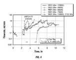
- FIG. 4shows a chart illustrating the decomposition of plugs made of polylactic acid fibers having different molecular weights (as evidenced by a rapid increase of flow through the plugs) at 250° F. (121° C.) and at 1000 and 2500 psi (6.89 and 17.24 MPa), in accordance with one embodiment of the invention.
- FIG. 5shows a chart illustrating the decomposition of plugs made of degradable materials and proppant, as evidenced by a rapid increase of flow through the plugs, in the presence of kerosene at 250° F. (121° C.) and 2500 psi (17.24 MPa), in accordance with one embodiment of the invention.
- FIG. 6shows a schematic illustrating the bridging and blocking of proppant in a fracture in accordance with one embodiment of the invention.
- FIG. 7A and FIG. 7Bshow a schematic illustrating plugging of a perforation in accordance with one embodiment of the invention.
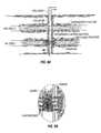
- FIG. 8A and FIG. 8Bshow a schematic illustrating plugging of a wellbore in accordance with one embodiment of the invention.
- FIG. 9A and FIG. 9Bshow a schematic illustrating plugging of a wellbore by using a degradable material and other materials (such as sand) in accordance with one embodiment of the invention.
- Embodiments of the inventionrelate to methods for temporarily blocking wellbores, perforations, or formation fractures so that other work (e.g., fracturing of other zones, workover, well repair, installation of downhole equipment, etc.) can be performed more efficiently or without damaging existing fractures.
- the temporary blockingis achieved by using degradable materials that will degrade within a desired period of time.
- the techniques of the inventionare similar to the ISDT's that are currently used on U.S. land.
- Degradable materialshave been used for fluid loss control and for diversion in the past. Examples include rock salt, graded rock salt, benzoic acid flakes, wax beads, wax buttons, oil-soluble resin material, etc. However, these materials have been used in sizes and shapes designed to build filter cakes on wellbore or fracture faces; they have not been used to plug wellbores, perforations, or fractures.
- Such materialsinclude inorganic fibers, for example of limestone or glass, but are more commonly polymers or co-polymers of esters, amides, or other similar materials. They may be partially hydrolyzed at non-backbone locations. Examples include polyhydroxyalkanoates, polyamides, polycaprolactones, polyhydroxybutyrates, polyethyleneterephthalates, polyvinyl alcohols, polyvinyl acetate, partially hydrolyzed polyvinyl acetate, and copolymers of these materials.
- Polymers or co-polymers of estersfor example, include substituted and unsubstituted lactide, glycolide, polylactic acid, and polyglycolic acid.
- Polymers or co-polymers of amidesmay include polyacrylamides. Materials that dissolve at the appropriate time under the encountered conditions are also used, for example polyols containing three or more hydroxyl groups.
- Polyols useful in the present inventionare polymeric polyols solubilizable upon heating, desalination or a combination thereof, and consist essentially of hydroxyl-substituted carbon atoms in a polymer chain spaced from adjacent hydroxyl-substituted carbon atoms by at least one carbon atom in the polymer chain. In other words, the useful polyols are preferably essentially free of adjacent hydroxyl substituents.
- the polyolshave a weight average molecular weight greater than 5000 up to 500,000 or more, and from 10,000 to 200,000 in another embodiment.
- the polyolsmay if desired be hydrophobically modified to further inhibit or delay solubilization, e.g. by including hydrocarbyl substituents such as alkyl, aryl, alkaryl or aralkyl moieties and/or side chains having from 2 to 30 carbon atoms.
- the polyolsmay also be modified to include carboxylic acid, thiol, paraffin, silane, sulfuric acid, acetoacetylate, polyethylene oxide, quaternary amine, or cationic monomers.
- the polyolis a substituted or unsubstituted polyvinyl alcohol that can be prepared by at least partial hydrolysis of a precursor polyvinyl material with ester substituents.
- the degradationmay be assisted or accelerated by a wash containing an appropriate dissolver or that changes the pH or salinity.
- the degradationmay also be assisted by an increase in temperature, for example when the treatment is performed before steamflooding.
- degradablewe include all of these suitably dissolvable materials.
- These materialsare typically used at high concentrations (e.g., >60 lbm/1,000 gal (>7.2 g/L)) in order to form temporary plugs or bridges.
- concentrationscan be lower if the fiber slurry can lose water, which concentrates the fibers.
- concentrations of these materials that can be usedmay be limited by the surface addition and blending equipment available.
- degradable or dissolvable materialsmay be in any shape: for example, powder, particulates, chips, fiber, bead, ribbon, platelet, film, rod, strip, spheroid, toroid, pellet, tablet, capsule, shaving, any round cross-sectional shape, any oval cross-sectional shape, trilobal shape, star shape, flat shape, rectangular shape, cubic, bar shaped, flake, cylindrical shape, filament, thread, or mixtures thereof
- the degradable or dissolvable materialsare solid materials, either amorphous or/and crystalline in nature, and generally are not liquid materials. Material densities are not critical, and will preferably range from below about 1 to about 4 g/cm 3 or more.
- the materialsmay be naturally occurring and synthetically prepared, or mixture thereof
- These degradable or dissolvable materialsmay even be biodegradable or composed of synthetic organic polymers or elastomers, as well as particular inorganic materials, or any mixtures of such materials.
- the degradable or dissolvable materialsare preferably present in the treatment fluid as a finely divided or dispersed material, while not used as a bulk phase or solid bulk form.
- fibersrefers to bodies or masses, such as filaments, of natural or synthetic material(s) having one dimension longer than the other two, which are at least similar in size, and further includes mixtures of such materials having multiple sizes and types.
- the fibersmay have a length of about 2 to about 25 mm, preferably about 3 to about 18 mm.
- the fibershave a denier of about 0.1 to about 20, preferably about 0.15 to about 6.
- the fiberspreferably degrade under downhole conditions in a duration that is suitable for the selected operation.
- the fibersmay have a variety of shapes ranging from simple round or oval cross-sectional areas to more complex shapes such as trilobe, figure eight, star-shape, rectangular cross-sectional, or the like.
- fiberspreferably, generally straight fibers with round or oval cross sections will be used. Curved, crimped, branched, spiral-shaped, hollow, fibrillated, and other three dimensional fiber geometries may be used. Again, the fibers may be hooked on one or both ends.
- Methods of the inventionmay be used for any appropriate treatment, including fracturing, workover, wellbore cleanout, gravel packing, acid diversion, fluid loss control, diversion, cementing, acidizing, matrix acidizing, scale control, water control, sand control, completion or other types of operations/formation stimulation techniques.
- hydraulic fracturingAs an example to illustrate embodiments of the invention. It will also be assumed, as an example, that sequential fracturing starts at the bottom of a vertical well, or the distal end of a horizontal well, and progresses toward the wellhead. Of course, other sequences are possible, depending upon the stress profile. One of ordinary skill in the art would appreciate that this is not intended to limit the scope of the invention to hydraulic fracturing. Instead, methods of the invention may also be used in other operations, such as temporary plugging of fractures or wellbores.
- Some embodiments of the inventionrelate to temporarily blocking of already-created fractures so that other zones may be fractured.
- a degradable or dissolvable materialis pumped to temporarily plug a completed fracture.
- the temporary pluglocks the proppants in a fracture, making them immobile and causing substantial stress increase and diversion in lower zones by means of a significant net pressure increase due to the high likelihood of proppant bridging with the degradable materials.
- a degradable material that can create a temporary packeris pumped after the proppant stages to temporarily seal the fracture by sealing the perforations.
- the plugis formed in the wellbore to seal the perforations leading to the fracture.
- a plugis formed in more than one of these locations.
- Degradable materialshave been used in other downhole operations, such as disclosed in U.S. patent application Ser. No. 11/156,966 filed on Jun. 20, 2005, by Willberg et al., entitled “Degradable Fiber Systems for Stimulation.” This application is assigned to the assignee of the present invention and is incorporated by reference in its entirety.
- the degradable materials that may be used in accordance with embodiments of the inventioncan be comprised of various chemical compositions as long as they can degrade within the desired time period under the downhole conditions, which may include temperatures as high as 350° F. (about 180° C.) or more and pressures as high as 20,000 psi (137.9 MPa) or more.
- some embodiments of the inventionrelate to degradable material assisted diversion and other embodiments relate to sealing of existing fractures, perforations, or wellbores.
- the followingwill describe the desired properties of the degradable materials in accordance with these purposes: as stress diversion agents or as sealers of perforations, fractures, or wellbores.
- stress diversion multi-stage fracturingthe stress should exceed the breakdown pressure and the net pressure increase during the subsequent stages.
- Stress or pressure for diversion to subsequent fracturing stagesmay result from at least four mechanisms: (1) normal increases in stress with depth; (2) pipe friction; (3) temporary supercharge from fracturing (net pressure); and (4) increased stress on proppants. Each of these factors will be analyzed in detail. (Another mechanism of stress diversion that naturally occurs in any job using polymer as the viscosifier is concentration of the polymer gel due to fluid loss, but this will not be discussed further.)
- In-situ formation stressmay arise from overburden stress, thermal stress, and tectonic strains.
- the common estimate for fracture pressure increaseis 0.62 psi/ft (14 kPa/m). This suggests that identical rocks with normal pressure gradient have 620 psi (4.27 MPa) of diverting power per 1000 ft (304.8 m) of separation.
- fracture pressure distributionis not homogeneous (it is usually a function of the lithology and of the pore pressure of the layers in question) and does not vary linearly with depth. Therefore, additional energy often needs to be added to the system in order to ensure that the ISD technique works consistently.
- Pipe frictiondecreases the bottomhole pressure with depth. This has a positive effect on the Stress Diversion.
- the friction pressurenormally does not exceed 1000 psi/1000 ft (22.6 kPa/m).
- the friction pressure diversion at beste.g., for very viscous fluids
- a recent trendis to use low polymer loading for fracturing fluids. Such fracturing fluids will have low viscosity, and hence, lower friction pressure.
- friction pressuredoes not play an important role in a typical fracturing job using the ISD techniques.
- the limited number of perforationscreates an artificial friction pressure, not due to the fluid, but rather due to the limited number of perforations.
- Fracturing superchargecomes from the need to overcome the breakdown pressure to initiate the fracturing process. Breakdown pressures are typically 5-10% higher than the fracture extension pressure, which is about the same as the closure stress. Typical values for fracture differential gradients are 0.1-0.2 psi/ft (2.26-4.53 kPa/m) at a depth around 10,000 ft (3048 m). This implies that it is worthwhile to have considerable excess net pressure in the first (lower) fracture to overcome the breakdown pressure of the upper zone. However, to be useful, the supercharge pressure in the first fracture should not be released via flowback.
- FIG. 2shows a chart of excess pressures typically required to fracture a formation at different depths (curve 21 for 5000 ft (1524 m); curve 22 for 6000 ft (1829 m); and curve 23 for 7000 ft (2134 m)).
- the fracture gradientis 0.65 psi/ft (14.7 kPa/m)
- the breakdown pressure gradientis 0.75 psi/ft (17 kPa/m). It is evident from FIG. 2 that the deeper the pay zones are, the higher the required excess pressures are for a given spacing between pay sands.
- the required excess pressure in the first fractureis approximately 370 psi (2551 kPa) (see curve 23 ).
- the required excess pressuremay be as high as 2,000 psi (13.8 MPa) at depths higher than 10,000 ft (3048 m).
- closure stress on proppantWhen pumping stops after fracturing, the fractures will close on the proppant that has entered the fractures.
- Common industry practice for estimating closure stress on proppantis to subtract flowing bottomhole pressure from the estimated in-situ stress of the pay interval fractured.
- closure stress on proppantcan be significantly higher than expected due to the influence of the bounding layers. See Schubarth et al., “Understanding Proppant Closure Stress,” SPE 37489, SPE Production Operations Symposium, Oklahoma City, Okla., U.S.A., Mar. 9-11, 1997. Normally, a fracture does not propagate within the targeted sand bordering the lower and upper shales where the closure stress is higher.
- the stress differential between sand in the pay zone and sand at the boundariesmay vary between 500 and 2500 psi (3.44 and 17.2 MPa).
- the thickness of a pay intervalcan vary from 20 to 200 ft (6.1 to 61 m). Based on these values, it has been shown that the excess closure pressure can vary from 300 psi (2.1 MPa) for a 200 ft (61 m) thick pay sand to 1500 psi (10.34 MPa) for a 20 ft (6.1 m) thick pay sand, assuming 1500 psi (10.34 MPa) in-situ pressure differential at the sand-shale boundaries (see FIG. 3 ).
- Inequality (5)indicates that if the net pressure in the first fracture is fully released (due to flowback or leak-off), then there is an excessive pressure of 325 psi (2.24 kPa) to divert the next stage. In low permeable hard rocks, a typical value for the net pressure may vary between 1000 and 2000 psi (6.9 and 13.8 MPa). This means that the ISD margin of safety may easily be exceeded in the case of first stage flowback.
- Embodiments of the inventionprovide more reliable diversion methods by adding degradable materials to enhance the net stress of the pay zone that was just fractured.
- the degradable materialsmay be fibers, powders, or any other forms.
- Laboratory and field experimentshave shown that at high concentrations of fibers, the proppant-fiber slurry may bridge. As a result, the job may screen out. This will lead to a significant increase in the net pressure and to good near-wellbore proppant placement. Such a procedure may be called a “tail screenout.”
- Studieshave also shown that fiber bridging is a complicated phenomenon, which requires special modeling to design such a job properly.
- U.S. patent application Ser. No. 10/214,817 filed on Aug. 8, 2002, by Boney et al.discloses methods and compositions designed to cause tip screenouts. This application is assigned to the assignee of the present invention and is incorporated by reference in its entirety.
- FIG. 3shows that the incremental stress on proppants may successfully substitute for the surcharge pressures described above, if one fractures several thin pay zones simultaneously in the first stage of fracturing.
- high degradable material concentrations at the tail end of a treatmentmay be used to: (a) sustain proppants, (i.e. to reduce settling rate during and after treatments and to reduce proppant flowback); and (b) ensure larger net surcharge pressure in the preceding stages.
- DMADdegradable material assisted diversion
- modelingmay also be used to design proper parameters for the degradable material assisted diversion.
- Various modeling techniquesare known in the art for designing various jobs in downhole environments, such as well stimulation, completion, etc.
- One of ordinary skill in the artwould appreciate that any of such modeling techniques may be used with the DMAD techniques of the invention.
- Some embodiments of the inventionrelate to the use of degradable materials as sealers to temporarily block perforations, fractures, or wellbores such that other operations may be performed without interference from or damage to the existing fractures.
- degradable materialsare used as sealers of wellbores, perforations, or fractures, all of the above-described mechanisms for diversion are also applicable.
- high concentrationse.g., >60 lbm/1,000 gal (>7.2 g/L)
- a degradable materialfor example in fiber form, may be pumped after the proppant stages to temporarily seal the wellbore, perforations, or fractures with fiber networks and to divert the subsequent stages.
- FIG. 4shows lifetimes of fiber plugs made of polylactic acids (PLA) having different molecular weights.
- PLApolylactic acids
- the higher molecular weight fiber plugshave longer lifetimes under the testing conditions (250° F. (121° C.); 1000 psi (6.9 MPa)).
- the plug having a polymer with a molecular weight of 77,600has a lifetime of several hours, while plugs made of higher molecular weight polymers have longer lifetimes (up to 6 hours).
- the lifetimes of plugsmay also be increased by using delay agents that protect the polymers from degradation.
- the main degradation mechanismis hydrolysis.
- a hydrophobic agentto the polymer (or plug), for example as a coating, the rates of hydrolysis will be reduced.
- the lifetimes of the polymers(hence, the lifetimes of the plugs) will be increased. Therefore, it is possible to control the lifetimes of plugs to suit the purposes of the operations.
- Some embodiments of the inventionuse degradable fiber plugs as described above.
- Other embodiments of the inventionuse plugs that are formed of degradable fibers and another material, such as proppants, other particulates (such as sand), or degradable absorbents (such as polyacrylic acid-co-acrylamide).
- the inclusion of an absorbent materialmay help fill pores inside a plug and make it stronger.
- RCP proppants or small grain size non-RCP proppantsgives quite satisfactory results: RCP/fiber plugs are able to withstand a pressure differential of 2500 psi (17.2 MPa) at 250° F. (121° C.) for several hours, as shown in FIG. 5 .
- degradable materialsare used in combination with methods of increasing the solid content of a slurry using particle-size distribution technology.
- particle-size distribution technologyWith a properly chosen multi-modal distribution of particle sizes, smaller particles fill the void spaces between larger ones, resulting in a slurry requiring less water.
- Typical distributionsuse two or three distinct particle size ranges. This provides a slurry with improved flow properties and excellent set properties such as permeability and strength.
- some embodiments of the inventionuse proppants of different sizes instead of RCP's. With these embodiments, the proppant compositions may be optimized to achieve sufficient conductivity of the plugs after the fibers are degraded.
- degradable or dissolvable materialssuch as a polylactic acid fiber
- their downhole lifetimescan be easily varied (e.g., by adding delay agents to increase their lifetimes)
- this approachis very attractive in the DMAD technique.
- the chemical lifetimes in the wellbore and the fracturepreferably are not shorter than 2-3 hours.
- their lifetimespreferably do not exceed a certain limit to allow one to flow back formations with extremely low leakoff. This indicates that an appropriate selection of the sealer type and additives is important.
- the degradable material sealermay be an excellent diversion tool, providing excess pressure up to or higher than 2000 psi (13.8 MPa).
- DMADDegradable Material Assisted Diversion
- embodiments of the inventionuse degradable materials to block a perforation, fracture, or wellbore temporarily so that work may be performed in other zones.
- a degradable materialis pumped at a high concentration to temporarily plug a completed fracture, and to lock the proppant in a fracture making it immobile and causing substantial stress increase and diversion from lower zones by means of a significant net pressure increase due to a higher likelihood of proppant bridging.
- a degradable material that can create a temporary packeris pumped after the proppant stages to temporarily seal the perforations associated with the fracture, or to temporarily seal the wellbore adjacent to these perforations.
- Degradable materialswill dissolve with time and unplug the fracture.
- the degradable materialsmay be of a variety of properties, shapes and compositions.
- the material decay or disintegrationmay be chemically, temperature or mechanically driven.
- Methods of the inventionmay be performed with any suitable equipment used in the industry, such as coiled tubing that is installed in the well ready to jet new perforations. While methods of the invention are conceptually similar to ISDT, the degradable material assisted diversion (DMAD) techniques of the invention guarantee much higher and more reliable stress diversion.
- DMADdegradable material assisted diversion
- FIG. 6shows a schematic representation of a method in accordance with some embodiments of the invention.
- a degradable material/chemicalis added at the tail end of the proppant stages to induce proppant bridging.
- the addition of the materialsubstantially increases the likelihood of proppant bridging in the fracture created in an earlier stage (shown as pay zone 1 ).
- proppantsare locked in the fractures, which prevents flowback and helps retain the supercharge stress in pay zone 1 (shown as a dashed line pressure profile to the right).
- Proppant bridgingmay also induce a near-wellbore screen-out, which in turn can substantially increase the fracture supercharge in pay zone 1 .
- the supercharge stress in pay zone 1will divert the fracture fluids to the next pay zone to be fractured (shows as pay zone 2 ).
- the added degradable materialsmay have various shapes (e.g., particulates or fibers).
- the sizes of the additivespreferably should be selected based on the fracture width; they should be less than the fracture openings so that they can enter the fractures.
- the degradable materialshould withstand formation conditions for a desired duration (such as 3-6 hours), i.e., the compatibility demands should be met.
- FIGS. 7A and 7Bshow another method in accordance with one embodiment of the invention.
- a degradable materialis pumped at high concentration after the proppant stages.
- the chemical along with proppantclogs up the perforations, creating a temporary seal.
- a temporary seal (or plug) formed of a degradable materialmay withstand over 2500 psi (17.2 MPa) pressure differential at 250° F. (121° C.) for several hours depending on the formation conditions (see FIGS. 4-6 ).
- the seal or plugconsists of one or more degradable materials only.
- both materialsshould be compatible with reservoir fluids for the desired durations.
- FIGS. 8A and 8Bshow another method in accordance with one embodiment of the invention.
- a temporary bridge plugmay be formed in the wellbore.
- the temporary bridgeis formed of a degradable material.
- This methodextends the sealing to the wellbore in order to make sure that a preceding fracture is protected from re-fracturing (re-opening an existing fracture).
- a tail screenoutmay be induced.
- the amount of sand in the wellborewill be much less than using the Sand Plug technique.
- all the combinations and permutations of partially or completely plugging wellbores, perforations, and fracturesare embodiments of the invention.
- FIGS. 9A and 9Bshow another method in accordance with one embodiment of the invention.
- a degradable materialis pumped together with proppant at the tail end of a fracturing treatment to create a composite plug in the perforations and/or wellbore.
- No induced tail screenoutis needed. In this case, the best stage diversion may be achieved.
- the degradable materialsshould be selected such that they will survive for several hours in the wellbore.
- a possible disadvantage of the embodimentis the sand production from the material in the wellbore during flowback when the sealing material is gone.
- methods of the inventionthat form temporary bridges or seals in the perforations, fracture(s), wellbore, or any combination of these are used for subsequent fracturing or for other operations to be performed downhole.
- the wellmay undergo various treatments instead of subsequent fracturing.
- the wellboremay be repaired (acid treatments), or installation of an electric submersible pump (ESP) may be performed.
- the plugging agentcan be selected to last sufficiently long to protect the formation over the expected time period of the subsequent downhole operation.
- a fractureis temporarily sealed or blocked with a degradable material.
- the degradable materialis used to temporarily protect the fracture from post-job workover fluid damage, or to temporarily protect downhole equipment from fracture flowback damage.
- the selection of the degradable materialsdepends on the expected damage, bottomhole conditions, and the durations needed for protection.
- degradable materialsare preferably compatible with different pH fracturing fluids and with brines containing different concentrations of salts (such as sodium chloride NaCl, calcium chloride CaCl 2 , sodium bromide NaBr, potassium chloride KCl, and others).
- the degradable materialsshould be compatible with temperature ranges as wide as possible. It is preferred that the degradable materials are compatible with temperatures greater than 32° F. (0° C.). Degradable materials should be compatible with weighted brines or completion fluids as well.
- different types of chemicalsmay be pumped to accelerate or delay degradable material decomposition.
- delay agentsmay include any type of hydrophobic material (for example, kerosene, oil, diesel, polymers, surfactants, etc), which will cover the surfaces of the degradable materials to slow their interactions with water.
- hydrophobic materialfor example, kerosene, oil, diesel, polymers, surfactants, etc
- polyolsfor example, such as partially hydrolyzed polyvinyl acetate, for example, salts may be included in the fluid; high ionic strength decreases the solubility of such materials.
- accelerator agentsmay include any high or low pH liquids (for example caustic or acid solutions), which will accelerate the decomposition of the degradable materials.
- methods of the invention for diversion or sealing of formation fractures using degradable materialsmay be based on results obtained from modeling.
- various formation modeling techniquesare available for hydraulic fracturing, such as Schlumberger's FracCADE stimulatorTM and the methods disclosed in U.S. Pat. No. 6,876,959 issued to Pierce et al., which is assigned to the assignee of the present invention and is hereby incorporated by reference in its entirely.
- Other available softwarefor example, includes pseudo three-dimensional (P3D) hydraulic fracture simulators and planar three-dimensional (PL3D) hydraulic simulators (including GOHFERTM from Stim-Lab and Marathon Oil Co.).
- Embodiments of the inventionare not limited to any particular modeling method.
- modelingis used to simulate induced stress diversion for the formation of interest. Then, the types and amounts of fluids to be used, and the durations and pumping rates for the fracturing job are accordingly selected.
- Embodiments of the inventionprovide efficient methods for diverting stress/pressures for staged fracturing.
- One of ordinary skill in the artwould appreciate that these methods may be applied in any type of well, including vertical, deviated or horizontal wells, and open or cased hole.
- the degradable materialsmay be used in acid fracturing.
- the degradable materialsform temporary blocks in the high permeability zones to divert the acid frac to the zones in need of treatments.
- the acid fracturingmay use a solid acid precursor, for example.
- the solid acid precursormay be lactide, glycolide, polylactic acid, polyglycolic acid, a copolymer of polyacetic acid and polyglycolic acid, a copolymer of glycolic acid with other hydroxyl-, carboxylic acid-, or hydroxycarboxylic acid-containing moieties, a copolymer of lactic acid with other hydroxyl-, carboxylic acid-, or hydroxycarboxylic acid-containing moieties, or mixture of the preceding.
- the solid acidmay be mixed with a second solid that reacts with an acid to increase the rate of dissolution and hydrolysis of the solid acid precursor.
- embodiments of the inventionmay also be used to temporarily plug the fractures or wellbore in order to achieve the desired effects or to perform other work.
- methods of the inventionmay be used to temporarily shut in the well after fracturing so that the fractures can relax.
- the durationis typically short, about 0.5 hour, for example.
- the degradable plugs in accordance with embodiments of the inventionmay also be used as “kill pills” to temporarily plug perforations or fractures.
- the addition of the degradable materials in accordance with embodiments of the inventionmay be practiced with existing equipment.
- the degradable materialsmay be mixed with proppants in blenders.
- the addition of the chemicals (degradable materials or other additives)may be managed by means of a modified feeder or a flush kit.
- coiled tubingfor the injection (addition) of delay or accelerator agents.
- degradable materialsvia coiled tubing or tubing while simultaneously fracturing down the annulus between the coiled tubing and the casing.
- the degradable materialswould mix with proppant or simply follow the proppant in the casing to cause the bridging.
- the methods of the inventionmay also be combined with methods of using fibers to assist in the transport of proppant, for example in slickwater treatments, for example as described in U.S. patent application Ser. No. 11/156,966, entitled “Degradable Fiber Systems For Stimulation”, filed Jun. 20, 2005, assigned to the same assignee as the present application, and hereby incorporated in its entirety.
- the methodsmay also be used in treatments in which fibers are also used in proppant-free fluids such as in the pads of fracturing treatments, or in prevention of fluid loss into natural fractures, for example as described in U.S. patent application Ser. No. 11/206,898, entitled “Methods For Controlling Fluid Loss,” filed Aug.
- the same fiberis used in all stages of these combination treatments.
- the same degradable fiberis used in the pad of a fracturing treatment stage, and/or in the main fracturing fluid of the stage to assist proppant transport, and at the end of the stage for degradable material assisted diversion.
- the pumping ratemay be reduced at the end of a fracturing stage to promote screenout, for example of fibers and proppant in hydraulic fracturing or of fibers in acid fracturing.
- the first fracturewill be placed in the weakest part of the formation, which could be at the wellhead end, the far end, or anywhere in between, and the layers could be fractured in any sequence. If one or more plugs are in the wellbore rather than in the fractures, this would require removing one or more plugs during the treatment.
Landscapes
- Life Sciences & Earth Sciences (AREA)
- Chemical & Material Sciences (AREA)
- General Life Sciences & Earth Sciences (AREA)
- Engineering & Computer Science (AREA)
- Materials Engineering (AREA)
- Organic Chemistry (AREA)
- Mining & Mineral Resources (AREA)
- Geology (AREA)
- Fluid Mechanics (AREA)
- Environmental & Geological Engineering (AREA)
- Physics & Mathematics (AREA)
- Geochemistry & Mineralogy (AREA)
- Chemical Kinetics & Catalysis (AREA)
- General Chemical & Material Sciences (AREA)
- Sealing Material Composition (AREA)
- Nonwoven Fabrics (AREA)
Abstract
Description
- the first pay sand is fractured and has a temporary supercharge of Δ1psi;
- the supercharge Δ1is sufficient to divert the second stage;
- there is a normal stress increase with depth of 0.65 psi/ft (14.7 kPa/m); and
- the friction pressure of the fracturing fluid is 500 psi/1000 ft (11.3 kPa/m).
- With these assumptions, the governing equations can be written as:
- For the first zone:
ps+pHS1−pfr1≦σmin1+Δ1 (1) - For the second zone:
ps+pHS2−pfr2−σmin2=Δ2 (2) - where psis the surface pressure, pHSiis the hydrostatic pressure for the ith-zone, pfr iis the ith friction pressure, σminiis the ith in-situ stress, and Δ2is the net pressure in the second zone.
Δ2−pHS2+pfr2+σmin2+pHS1−pfr1≦σmin1+Δ1 (3)
or
Δ2+ΔpHS≦Δ1+Δpfr+Δσmin (4)
where Δp denotes p1−p2. The right-hand side of inequality (4) describes the positive isolation mechanisms or induced stresses, while the left-hand part is the required excess pressure. With the assumptions listed above, ΔpHS=50 psi/100 ft (11.3 kPa/m), Δpfr=50 psi/100 ft (11.3 kPa/m), and Δσmin=65 psi/100 ft (14.7 kPa/m). Substituting these numbers into inequality (4), one obtains for a spacing of 500 ft (152.4 m):
Δ1≧Δ2−325 psi (2.24 kPa) (5)
- 1) The chemicals (degradable materials) may be sensitive to the environment, so there may be dilution and precipitation issues. The sealer preferably should survive in the formation or wellbore for a sufficiently long duration (e.g., 3-6 hours). The duration should be long enough for: (a) wireline services to perforate the next pay sand; (b) subsequent fracturing treatment(s) to be completed; and (c) the fracture to close on the proppant before it completely settles, providing the best fracture conductivity. In tight gas formations with low leakoff, this may be an issue.
- 2) Degradable Material Sealers will allow no flowback. As a result, the fracture will be supercharged for a much longer period. This is good for diversion. However, in low leakoff formations, the shut-in time may become too long, which may result in proppant settling. In this case, flowback after the degradable materials is broken may be used to aid in suspending the proppant in the fracture.
- the first pay sand is fractured and has a temporary supercharge of Δ1psi;
- the sealing ability of the material is pMS=1000 psi (6.9 MPa);
- the induced stress is enough to divert the subsequent stage;
- there is a normal stress increase with depth of 0.65 psi/ft (14.7 kPa/m);
- fracturing fluid friction pressure is 500 psi/1000 ft (11.3 kPa/m); and
- the hydrostatic pressure difference is 500 psi (3.45 MPa).
- With these assumptions the governing equation (4) can be rewritten as:
Δ2+ΔpHS≦Δ1+Δpfr+Δσmin+pMS (6) - For stage spacing of 500 ft this will give
Δ1≧Δ2−1325 psi (9.1 MPa) (7)
Claims (32)
Priority Applications (1)
| Application Number | Priority Date | Filing Date | Title |
|---|---|---|---|
| US12/040,517US7775278B2 (en) | 2004-09-01 | 2008-02-29 | Degradable material assisted diversion or isolation |
Applications Claiming Priority (5)
| Application Number | Priority Date | Filing Date | Title |
|---|---|---|---|
| US60627004P | 2004-09-01 | 2004-09-01 | |
| US11/156,966US7275596B2 (en) | 2005-06-20 | 2005-06-20 | Method of using degradable fiber systems for stimulation |
| US11/206,898US7350572B2 (en) | 2004-09-01 | 2005-08-18 | Methods for controlling fluid loss |
| US11/294,983US7380600B2 (en) | 2004-09-01 | 2005-12-05 | Degradable material assisted diversion or isolation |
| US12/040,517US7775278B2 (en) | 2004-09-01 | 2008-02-29 | Degradable material assisted diversion or isolation |
Related Parent Applications (1)
| Application Number | Title | Priority Date | Filing Date |
|---|---|---|---|
| US11/294,983Continuation-In-PartUS7380600B2 (en) | 2004-09-01 | 2005-12-05 | Degradable material assisted diversion or isolation |
Publications (2)
| Publication Number | Publication Date |
|---|---|
| US20080200352A1 US20080200352A1 (en) | 2008-08-21 |
| US7775278B2true US7775278B2 (en) | 2010-08-17 |
Family
ID=39707200
Family Applications (1)
| Application Number | Title | Priority Date | Filing Date |
|---|---|---|---|
| US12/040,517Active2026-01-27US7775278B2 (en) | 2004-09-01 | 2008-02-29 | Degradable material assisted diversion or isolation |
Country Status (1)
| Country | Link |
|---|---|
| US (1) | US7775278B2 (en) |
Cited By (57)
| Publication number | Priority date | Publication date | Assignee | Title |
|---|---|---|---|---|
| US20110226479A1 (en)* | 2008-04-15 | 2011-09-22 | Philipp Tippel | Diversion by combining dissolvable and degradable particles and fibers |
| US8439116B2 (en) | 2009-07-24 | 2013-05-14 | Halliburton Energy Services, Inc. | Method for inducing fracture complexity in hydraulically fractured horizontal well completions |
| WO2013161754A1 (en) | 2012-04-27 | 2013-10-31 | 株式会社クレハ | Short polyglycolic-acid-resin fibers for use in well-treatment fluid |
| WO2013162002A1 (en) | 2012-04-27 | 2013-10-31 | 株式会社クレハ | Polyester resin composition and molded article of same |
| WO2013161755A1 (en) | 2012-04-27 | 2013-10-31 | 株式会社クレハ | Short polyglycolic-acid-resin fibers and well-treatment fluid |
| US8631872B2 (en) | 2009-09-24 | 2014-01-21 | Halliburton Energy Services, Inc. | Complex fracturing using a straddle packer in a horizontal wellbore |
| US20140027127A1 (en)* | 2008-12-23 | 2014-01-30 | Frazier Ball Invention, LLC | Downhole tools having non-toxic degradable elements |
| US20140076571A1 (en)* | 2008-12-23 | 2014-03-20 | W. Lynn Frazier | Downhole tools having non-toxic degradable elements |
| US20140083717A1 (en)* | 2012-05-18 | 2014-03-27 | Frazier Technologies, L.L.C. | High-molecular-weight polyglycolides for hydrocarbon recovery |
| US8714249B1 (en) | 2012-10-26 | 2014-05-06 | Halliburton Energy Services, Inc. | Wellbore servicing materials and methods of making and using same |
| US8720555B2 (en) | 2009-11-18 | 2014-05-13 | Halliburton Energy Services, Inc. | Self-diverting high-rate water packs |
| US20140190685A1 (en)* | 2008-12-23 | 2014-07-10 | Frazier Technologies, L.L.C. | Downhole tools having non-toxic degradable elements and methods of using the same |
| US8857513B2 (en) | 2012-01-20 | 2014-10-14 | Baker Hughes Incorporated | Refracturing method for plug and perforate wells |
| US8887803B2 (en) | 2012-04-09 | 2014-11-18 | Halliburton Energy Services, Inc. | Multi-interval wellbore treatment method |
| US8936086B2 (en) | 2011-10-04 | 2015-01-20 | Halliburton Energy Services, Inc. | Methods of fluid loss control, diversion, and sealing using deformable particulates |
| US8960292B2 (en) | 2008-08-22 | 2015-02-24 | Halliburton Energy Services, Inc. | High rate stimulation method for deep, large bore completions |
| US8992769B2 (en) | 2012-05-16 | 2015-03-31 | Chevron U.S.A. Inc. | Process, method, and system for removing heavy metals from fluids |
| US9016376B2 (en) | 2012-08-06 | 2015-04-28 | Halliburton Energy Services, Inc. | Method and wellbore servicing apparatus for production completion of an oil and gas well |
| US9022112B2 (en) | 2010-05-20 | 2015-05-05 | Schlumberger Technology Corporation | Chelant based system and polylactide resin for acid diversion |
| US9023123B2 (en) | 2012-05-16 | 2015-05-05 | Chevron U.S.A. Inc. | Process, method, and system for removing mercury from fluids |
| US20150290858A1 (en)* | 2012-12-12 | 2015-10-15 | Kureha Corporation | Solidification- and extrusion-molded article of polyglycolic acid and method for manufacturing same |
| US9181497B2 (en) | 2012-05-16 | 2015-11-10 | Chevon U.S.A. Inc. | Process, method, and system for removing mercury from fluids |
| US20150330197A1 (en)* | 2014-05-19 | 2015-11-19 | Baker Hughes Incorporated | Use of an acid soluble or degradable solid particulate and an acid liberating or acid generating composite in the stimulation of a subterranean formation |
| US9316087B2 (en) | 2008-04-15 | 2016-04-19 | Schlumberger Technology Corporation | Sealing by ball sealers |
| US9394474B2 (en) | 2013-08-07 | 2016-07-19 | Magnablend Inc. | Methods and compositions for using temporary, slow degrading, particulate agents in a subterranean formation |
| US9410076B2 (en) | 2012-10-25 | 2016-08-09 | Halliburton Energy Services, Inc. | Wellbore servicing methods and compositions comprising degradable polymers |
| US9447675B2 (en) | 2012-05-16 | 2016-09-20 | Chevron U.S.A. Inc. | In-situ method and system for removing heavy metals from produced fluids |
| WO2016176381A1 (en)* | 2015-04-28 | 2016-11-03 | Schlumberger Technology Corporation | Well treatment |
| US9574418B2 (en) | 2012-07-10 | 2017-02-21 | Kureha Corporation | Downhole tool member for hydrocarbon resource recovery |
| US9617462B2 (en) | 2011-12-28 | 2017-04-11 | Schlumberger Technology Corporation | Degradable composite materials and uses |
| US9702238B2 (en) | 2012-10-25 | 2017-07-11 | Halliburton Energy Services, Inc. | Wellbore servicing methods and compositions comprising degradable polymers |
| US9765592B2 (en) | 2012-06-06 | 2017-09-19 | Exxonmobil Upstream Research Company | Systems and methods for secondary sealing of a perforation within a wellbore casing |
| US9796918B2 (en) | 2013-01-30 | 2017-10-24 | Halliburton Energy Services, Inc. | Wellbore servicing fluids and methods of making and using same |
| US9890317B2 (en) | 2013-10-22 | 2018-02-13 | Hallburton Energy Services, Inc. | Solids-free diverting agents and methods related thereto |
| US9951266B2 (en) | 2012-10-26 | 2018-04-24 | Halliburton Energy Services, Inc. | Expanded wellbore servicing materials and methods of making and using same |
| US10001613B2 (en) | 2014-07-22 | 2018-06-19 | Schlumberger Technology Corporation | Methods and cables for use in fracturing zones in a well |
| CN108316915A (en)* | 2017-12-20 | 2018-07-24 | 北京石油化工学院 | A kind of method that the optimal dosage of diversion agent is temporarily blocked up in determining oil/gas well compact reservoir |
| US10030465B2 (en)* | 2012-11-15 | 2018-07-24 | Kureha Corporation | Solidification- and extrusion-molded article of polyglycolic acid and method for manufacturing same |
| RU2675136C1 (en)* | 2014-11-19 | 2018-12-17 | Тойо Сейкан Груп Холдингз, Лтд. | Method for extracting underground resources and hydrolysis blocking agent therefor |
| US10161235B2 (en) | 2016-06-03 | 2018-12-25 | Enhanced Production, Inc. | Hydraulic fracturing in highly heterogeneous formations by resisting formation and/or sealing micro-fractures |
| US10301903B2 (en) | 2016-05-16 | 2019-05-28 | Schlumberger Technology Corporation | Well treatment |
| RU2700148C2 (en)* | 2013-11-14 | 2019-09-12 | Аркема Франс | Liquid composition for intensifying oil or gas production |
| US10421896B2 (en) | 2016-01-28 | 2019-09-24 | Halliburton Energy Services, Inc. | Polylactic acid/acid-soluble hard particulate blends as degradable diverting agents |
| US20200150307A1 (en)* | 2016-05-13 | 2020-05-14 | Gas Sensing Technology Corp. | Gross mineralogy and petrology using raman spectroscopy |
| US10738577B2 (en) | 2014-07-22 | 2020-08-11 | Schlumberger Technology Corporation | Methods and cables for use in fracturing zones in a well |
| RU2730575C1 (en)* | 2017-03-31 | 2020-08-24 | Шлюмберже Текнолоджи Б.В. | Formation hydraulic fracturing formation method and formation hydraulic fracturing method |
| US10808497B2 (en) | 2011-05-11 | 2020-10-20 | Schlumberger Technology Corporation | Methods of zonal isolation and treatment diversion |
| US10954431B2 (en) | 2017-10-03 | 2021-03-23 | Halliburton Energy Services, Inc. | Degradable diversion material having a urea compound |
| US11168555B2 (en) | 2017-06-09 | 2021-11-09 | Schlumberger Technology Corporation | Method for temporary isolation of well interval, method for hydraulic refracturing, and method for well killing |
| US11248167B2 (en) | 2016-06-30 | 2022-02-15 | Halliburton Energy Services, Inc. | Acid diversion in naturally fractured formations |
| US11254860B2 (en) | 2017-10-31 | 2022-02-22 | Halliburton Energy Services, Inc. | Diversion using solid particulates |
| US11401453B2 (en) | 2018-08-01 | 2022-08-02 | Halliburton Energy Services, Inc. | Multi-grade diverting particulates |
| US11407934B2 (en) | 2018-03-21 | 2022-08-09 | Halliburton Energy Services, Inc. | Degradable diversion material having a polyacrylate compound |
| US11466200B2 (en) | 2018-09-12 | 2022-10-11 | Halliburton Energy Services, Inc. | Multi-functional diverter particulates |
| US11572497B2 (en) | 2018-05-14 | 2023-02-07 | Halliburton Energy Services, Inc. | Pelletized diverting agents using degradable polymers |
| US11578252B2 (en) | 2018-11-30 | 2023-02-14 | Halliburton Energy Services, Inc. | Composite diverting particulates |
| US11859129B2 (en) | 2021-12-08 | 2024-01-02 | Altarock Energy Inc. | Methods of forming a permeable proppant pack in a geothermal formation |
Families Citing this family (49)
| Publication number | Priority date | Publication date | Assignee | Title |
|---|---|---|---|---|
| US10011763B2 (en) | 2007-07-25 | 2018-07-03 | Schlumberger Technology Corporation | Methods to deliver fluids on a well site with variable solids concentration from solid slurries |
| US9040468B2 (en) | 2007-07-25 | 2015-05-26 | Schlumberger Technology Corporation | Hydrolyzable particle compositions, treatment fluids and methods |
| EP2143874A1 (en)* | 2008-07-11 | 2010-01-13 | Welltec A/S | Sealing arrangement and sealing method |
| US20120048549A1 (en)* | 2009-01-30 | 2012-03-01 | Schlumberger Technology Corporation | Polymer Emulsions And Well Treatment Fluids |
| US8413719B2 (en)* | 2009-03-11 | 2013-04-09 | Schlumberger Technology Corporation | Relative permeability modification |
| CA2783399C (en) | 2009-12-09 | 2016-08-30 | Schlumberger Canada Limited | Method for increasing fracture area |
| US20120067581A1 (en)* | 2010-09-17 | 2012-03-22 | Schlumberger Technology Corporation | Mechanism for treating subteranean formations with embedded additives |
| US20120285695A1 (en)* | 2011-05-11 | 2012-11-15 | Schlumberger Technology Corporation | Destructible containers for downhole material and chemical delivery |
| US20130048282A1 (en)* | 2011-08-23 | 2013-02-28 | David M. Adams | Fracturing Process to Enhance Propping Agent Distribution to Maximize Connectivity Between the Formation and the Wellbore |
| US8720556B2 (en)* | 2011-11-30 | 2014-05-13 | Halliburton Energy Services, Inc. | Methods for initiating new fractures in a completed wellbore having existing fractures present |
| EP2860344A4 (en) | 2012-06-07 | 2016-01-06 | Kureha Corp | Member for hydrocarbon resource collection downhole tool |
| WO2014162793A1 (en)* | 2013-04-05 | 2014-10-09 | 昭和電工株式会社 | Injection material for fracturing and fluid for fracturing |
| JP6327946B2 (en) | 2013-05-31 | 2018-05-23 | 株式会社クレハ | Well drilling plug with mandrel formed from degradable material |
| US9366124B2 (en) | 2013-11-27 | 2016-06-14 | Baker Hughes Incorporated | System and method for re-fracturing multizone horizontal wellbores |
| JP6359888B2 (en) | 2013-12-27 | 2018-07-18 | 株式会社クレハ | Diameter-expandable annular degradable seal member for downhole tool, well drilling plug, and well drilling method |
| US20160290115A1 (en)* | 2014-01-09 | 2016-10-06 | Halliburton Energy Services, Inc. | Re-fracturing a fracture stimulated subterranean formation |
| US10018010B2 (en) | 2014-01-24 | 2018-07-10 | Baker Hughes, A Ge Company, Llc | Disintegrating agglomerated sand frack plug |
| CA2936851A1 (en)* | 2014-02-21 | 2015-08-27 | Terves, Inc. | Fluid activated disintegrating metal system |
| US9914868B2 (en)* | 2014-03-04 | 2018-03-13 | A. Schulman, Inc. | Methods and compositions for using temporary compacted materials as well servicing fluids in a subterranean formation |
| US10280699B2 (en) | 2014-03-07 | 2019-05-07 | Kureha Corporation | Degradable rubber member for downhole tools, degradable seal member, degradable protecting member, downhole tool, and method for well drilling |
| JP6363362B2 (en) | 2014-03-11 | 2018-07-25 | 株式会社クレハ | Downhole tool material for hydrocarbon resource recovery |
| US20160122620A1 (en)* | 2014-11-05 | 2016-05-05 | Schlumberger Technology Corporation | Compositions and Methods for Servicing Subterranean Wells |
| US10161222B2 (en)* | 2014-11-05 | 2018-12-25 | Schlumberger Technology Corporation | Compositions and methods for servicing subterranean wells |
| US9567825B2 (en) | 2015-04-28 | 2017-02-14 | Thru Tubing Solutions, Inc. | Flow control in subterranean wells |
| US9745820B2 (en) | 2015-04-28 | 2017-08-29 | Thru Tubing Solutions, Inc. | Plugging device deployment in subterranean wells |
| US10774612B2 (en) | 2015-04-28 | 2020-09-15 | Thru Tubing Solutions, Inc. | Flow control in subterranean wells |
| US10641069B2 (en) | 2015-04-28 | 2020-05-05 | Thru Tubing Solutions, Inc. | Flow control in subterranean wells |
| US10513653B2 (en) | 2015-04-28 | 2019-12-24 | Thru Tubing Solutions, Inc. | Flow control in subterranean wells |
| US10233719B2 (en) | 2015-04-28 | 2019-03-19 | Thru Tubing Solutions, Inc. | Flow control in subterranean wells |
| US9567826B2 (en) | 2015-04-28 | 2017-02-14 | Thru Tubing Solutions, Inc. | Flow control in subterranean wells |
| US10655427B2 (en)* | 2015-04-28 | 2020-05-19 | Thru Tubing Solutions, Inc. | Flow control in subterranean wells |
| US9567824B2 (en) | 2015-04-28 | 2017-02-14 | Thru Tubing Solutions, Inc. | Fibrous barriers and deployment in subterranean wells |
| US11761295B2 (en) | 2015-07-21 | 2023-09-19 | Thru Tubing Solutions, Inc. | Plugging device deployment |
| US20170088698A1 (en)* | 2015-09-28 | 2017-03-30 | Eastman Chemical Company | Cellulose ester materials with tunable degradation characteristics |
| US20170159402A1 (en)* | 2015-12-02 | 2017-06-08 | Baker Hughes Incorporated | Method of enhancing circulation during drill-out of a wellbore barrier using dissovable solid particulates |
| US10267133B2 (en) | 2016-06-06 | 2019-04-23 | Halliburton Energy Services, Inc. | Systems and methods for fracturing a subterranean formation |
| WO2017213624A1 (en) | 2016-06-06 | 2017-12-14 | Halliburton Energy Services, Inc. | Fracturing a subterranean formation |
| US11220623B2 (en) | 2016-06-06 | 2022-01-11 | Halliburton Energy Services, Inc. | Flow constraint material and slurry compositions |
| CN107664028B (en)* | 2016-07-29 | 2020-07-14 | 中国石油天然气股份有限公司 | Temporary plugging fracturing method and crack flow guide device |
| WO2018075097A1 (en)* | 2016-10-18 | 2018-04-26 | Thru Tubing Solutions, Inc. | Flow control in subterranean wells |
| US20190249516A1 (en)* | 2018-02-13 | 2019-08-15 | Parsley Energy, Inc. | Low pressure reservoir composite plug drill out |
| CN109184651A (en)* | 2018-08-31 | 2019-01-11 | 中国石油大学(北京) | Infinite stages fracturing process is temporarily blocked up in water-jet segmentation |
| CN109142151A (en)* | 2018-09-12 | 2019-01-04 | 中国石油天然气股份有限公司 | Method for evaluating adhesion capability performance of temporary plugging agent for oilfield fracturing |
| CN110305652A (en)* | 2018-09-13 | 2019-10-08 | 中海石油(中国)有限公司上海分公司 | Composite temporary plugging agent for fracturing and preparation method thereof |
| CN110069878B (en)* | 2019-04-29 | 2019-12-20 | 西南石油大学 | Quantitative scoring and optimizing method for well drilling completion plugging material |
| WO2020257112A1 (en) | 2019-06-19 | 2020-12-24 | Stepan Company | Polyester diverting agents for low-temperature oil wells |
| US12139992B2 (en) | 2019-06-20 | 2024-11-12 | Thru Tubing Solutions, Inc. | Discrete plugging device launcher |
| CN110984907A (en)* | 2019-12-23 | 2020-04-10 | 南智(重庆)能源技术有限公司 | Well repairing method based on low-leakage temporary plugging process |
| CN112647892A (en)* | 2020-12-28 | 2021-04-13 | 黑龙江弘力通能源技术服务有限公司 | Method for temporarily blocking large-scale underground fracturing hole |
Citations (44)
| Publication number | Priority date | Publication date | Assignee | Title |
|---|---|---|---|---|
| US3974077A (en) | 1974-09-19 | 1976-08-10 | The Dow Chemical Company | Fracturing subterranean formation |
| US4387769A (en) | 1981-08-10 | 1983-06-14 | Exxon Production Research Co. | Method for reducing the permeability of subterranean formations |
| US4715967A (en) | 1985-12-27 | 1987-12-29 | E. I. Du Pont De Nemours And Company | Composition and method for temporarily reducing permeability of subterranean formations |
| US4716964A (en) | 1981-08-10 | 1988-01-05 | Exxon Production Research Company | Use of degradable ball sealers to seal casing perforations in well treatment fluid diversion |
| US4836940A (en) | 1987-09-14 | 1989-06-06 | American Colloid Company | Composition and method of controlling lost circulation from wellbores |
| US4848467A (en) | 1988-02-16 | 1989-07-18 | Conoco Inc. | Formation fracturing process |
| US4957165A (en) | 1988-02-16 | 1990-09-18 | Conoco Inc. | Well treatment process |
| US4986355A (en) | 1989-05-18 | 1991-01-22 | Conoco Inc. | Process for the preparation of fluid loss additive and gel breaker |
| US5330005A (en) | 1993-04-05 | 1994-07-19 | Dowell Schlumberger Incorporated | Control of particulate flowback in subterranean wells |
| US5501275A (en) | 1993-04-05 | 1996-03-26 | Dowell, A Division Of Schlumberger Technology Corporation | Control of particulate flowback in subterranean wells |
| US5551516A (en) | 1995-02-17 | 1996-09-03 | Dowell, A Division Of Schlumberger Technology Corporation | Hydraulic fracturing process and compositions |
| US5551514A (en) | 1995-01-06 | 1996-09-03 | Dowell, A Division Of Schlumberger Technology Corp. | Sand control without requiring a gravel pack screen |
| US5667012A (en) | 1995-10-11 | 1997-09-16 | Schlumberger Technology Corporation | Method and apparatus for the addition of low-bulk-density fibers to a fluid |
| US5782300A (en) | 1996-11-13 | 1998-07-21 | Schlumberger Technology Corporation | Suspension and porous pack for reduction of particles in subterranean well fluids, and method for treating an underground formation |
| US5964295A (en) | 1996-10-09 | 1999-10-12 | Schlumberger Technology Corporation, Dowell Division | Methods and compositions for testing subterranean formations |
| US5979555A (en) | 1997-12-02 | 1999-11-09 | Akzo Nobel Nv | Surfactants for hydraulic fractoring compositions |
| US5990051A (en) | 1998-04-06 | 1999-11-23 | Fairmount Minerals, Inc. | Injection molded degradable casing perforation ball sealers |
| US6085844A (en) | 1998-11-19 | 2000-07-11 | Schlumberger Technology Corporation | Method for removal of undesired fluids from a wellbore |
| WO2000049272A1 (en) | 1999-02-18 | 2000-08-24 | Schlumberger Technology Corporation | Fracturing process and composition |
| US6140277A (en) | 1998-12-31 | 2000-10-31 | Schlumberger Technology Corporation | Fluids and techniques for hydrocarbon well completion |
| US6169058B1 (en) | 1997-06-05 | 2001-01-02 | Bj Services Company | Compositions and methods for hydraulic fracturing |
| US6258859B1 (en) | 1997-06-10 | 2001-07-10 | Rhodia, Inc. | Viscoelastic surfactant fluids and related methods of use |
| WO2001051767A2 (en) | 2000-01-14 | 2001-07-19 | Schlumberger Technology Corporation | Addition of solids to generate viscosity downhole |
| US6380138B1 (en) | 1999-04-06 | 2002-04-30 | Fairmount Minerals Ltd. | Injection molded degradable casing perforation ball sealers fluid loss additive and method of use |
| US6419019B1 (en) | 1998-11-19 | 2002-07-16 | Schlumberger Technology Corporation | Method to remove particulate matter from a wellbore using translocating fibers and/or platelets |
| US6509301B1 (en) | 1999-08-26 | 2003-01-21 | Daniel Patrick Vollmer | Well treatment fluids and methods for the use thereof |
| US20030060374A1 (en) | 2001-09-26 | 2003-03-27 | Cooke Claude E. | Method and materials for hydraulic fracturing of wells |
| US6691780B2 (en) | 2002-04-18 | 2004-02-17 | Halliburton Energy Services, Inc. | Tracking of particulate flowback in subterranean wells |
| US20040162356A1 (en) | 2002-09-20 | 2004-08-19 | Schlumberger Technology Corporation | Fiber Assisted Emulsion System |
| US20040261993A1 (en) | 2003-06-27 | 2004-12-30 | Nguyen Philip D. | Permeable cement and sand control methods utilizing permeable cement in subterranean well bores |
| US6837309B2 (en) | 2001-09-11 | 2005-01-04 | Schlumberger Technology Corporation | Methods and fluid compositions designed to cause tip screenouts |
| US6938693B2 (en) | 2001-10-31 | 2005-09-06 | Schlumberger Technology Corporation | Methods for controlling screenouts |
| US20050230107A1 (en) | 2004-04-14 | 2005-10-20 | Mcdaniel Billy W | Methods of well stimulation during drilling operations |
| US20060021753A1 (en) | 2004-07-30 | 2006-02-02 | Key Energy Services, Inc. | Method of Pumping an "In-the-Formation" Diverting Agent in a Lateral Section of an Oil and Gas Well |
| US20060032633A1 (en) | 2004-08-10 | 2006-02-16 | Nguyen Philip D | Methods and compositions for carrier fluids comprising water-absorbent fibers |
| US7004255B2 (en) | 2003-06-04 | 2006-02-28 | Schlumberger Technology Corporation | Fracture plugging |
| US20060118301A1 (en) | 2004-12-03 | 2006-06-08 | Halliburton Energy Services, Inc. | Methods of stimulating a subterranean formation comprising multiple production intervals |
| US7084095B2 (en) | 2001-04-04 | 2006-08-01 | Schlumberger Technology Corporation | Methods for controlling the rheological properties of viscoelastic surfactants based fluids |
| US20060169453A1 (en) | 2005-02-01 | 2006-08-03 | Savery Mark R | Kickoff plugs comprising a self-degrading cement in subterranean well bores |
| US7166560B2 (en) | 2002-10-28 | 2007-01-23 | Schlumberger Technology Corporation | Generating Acid Downhole in Acid Fracturing |
| US7275596B2 (en) | 2005-06-20 | 2007-10-02 | Schlumberger Technology Corporation | Method of using degradable fiber systems for stimulation |
| US7350572B2 (en)* | 2004-09-01 | 2008-04-01 | Schlumberger Technology Corporation | Methods for controlling fluid loss |
| US7380600B2 (en)* | 2004-09-01 | 2008-06-03 | Schlumberger Technology Corporation | Degradable material assisted diversion or isolation |
| US7398826B2 (en) | 2003-11-14 | 2008-07-15 | Schlumberger Technology Corporation | Well treatment with dissolvable polymer |
- 2008
- 2008-02-29USUS12/040,517patent/US7775278B2/enactiveActive
Patent Citations (49)
| Publication number | Priority date | Publication date | Assignee | Title |
|---|---|---|---|---|
| US3974077A (en) | 1974-09-19 | 1976-08-10 | The Dow Chemical Company | Fracturing subterranean formation |
| US4387769A (en) | 1981-08-10 | 1983-06-14 | Exxon Production Research Co. | Method for reducing the permeability of subterranean formations |
| US4716964A (en) | 1981-08-10 | 1988-01-05 | Exxon Production Research Company | Use of degradable ball sealers to seal casing perforations in well treatment fluid diversion |
| US4715967A (en) | 1985-12-27 | 1987-12-29 | E. I. Du Pont De Nemours And Company | Composition and method for temporarily reducing permeability of subterranean formations |
| US4836940A (en) | 1987-09-14 | 1989-06-06 | American Colloid Company | Composition and method of controlling lost circulation from wellbores |
| US4848467A (en) | 1988-02-16 | 1989-07-18 | Conoco Inc. | Formation fracturing process |
| US4957165A (en) | 1988-02-16 | 1990-09-18 | Conoco Inc. | Well treatment process |
| US4986355A (en) | 1989-05-18 | 1991-01-22 | Conoco Inc. | Process for the preparation of fluid loss additive and gel breaker |
| US5330005A (en) | 1993-04-05 | 1994-07-19 | Dowell Schlumberger Incorporated | Control of particulate flowback in subterranean wells |
| US5439055A (en) | 1993-04-05 | 1995-08-08 | Dowell, A Division Of Schlumberger Technology Corp. | Control of particulate flowback in subterranean wells |
| US5501275A (en) | 1993-04-05 | 1996-03-26 | Dowell, A Division Of Schlumberger Technology Corporation | Control of particulate flowback in subterranean wells |
| US6172011B1 (en) | 1993-04-05 | 2001-01-09 | Schlumberger Technolgy Corporation | Control of particulate flowback in subterranean wells |
| US5551514A (en) | 1995-01-06 | 1996-09-03 | Dowell, A Division Of Schlumberger Technology Corp. | Sand control without requiring a gravel pack screen |
| US5551516A (en) | 1995-02-17 | 1996-09-03 | Dowell, A Division Of Schlumberger Technology Corporation | Hydraulic fracturing process and compositions |
| US5667012A (en) | 1995-10-11 | 1997-09-16 | Schlumberger Technology Corporation | Method and apparatus for the addition of low-bulk-density fibers to a fluid |
| US5964295A (en) | 1996-10-09 | 1999-10-12 | Schlumberger Technology Corporation, Dowell Division | Methods and compositions for testing subterranean formations |
| US5979557A (en) | 1996-10-09 | 1999-11-09 | Schlumberger Technology Corporation | Methods for limiting the inflow of formation water and for stimulating subterranean formations |
| US5782300A (en) | 1996-11-13 | 1998-07-21 | Schlumberger Technology Corporation | Suspension and porous pack for reduction of particles in subterranean well fluids, and method for treating an underground formation |
| US6169058B1 (en) | 1997-06-05 | 2001-01-02 | Bj Services Company | Compositions and methods for hydraulic fracturing |
| US6258859B1 (en) | 1997-06-10 | 2001-07-10 | Rhodia, Inc. | Viscoelastic surfactant fluids and related methods of use |
| US5979555A (en) | 1997-12-02 | 1999-11-09 | Akzo Nobel Nv | Surfactants for hydraulic fractoring compositions |
| US5990051A (en) | 1998-04-06 | 1999-11-23 | Fairmount Minerals, Inc. | Injection molded degradable casing perforation ball sealers |
| US6085844A (en) | 1998-11-19 | 2000-07-11 | Schlumberger Technology Corporation | Method for removal of undesired fluids from a wellbore |
| US6419019B1 (en) | 1998-11-19 | 2002-07-16 | Schlumberger Technology Corporation | Method to remove particulate matter from a wellbore using translocating fibers and/or platelets |
| US6140277A (en) | 1998-12-31 | 2000-10-31 | Schlumberger Technology Corporation | Fluids and techniques for hydrocarbon well completion |
| WO2000049272A1 (en) | 1999-02-18 | 2000-08-24 | Schlumberger Technology Corporation | Fracturing process and composition |
| US6599863B1 (en) | 1999-02-18 | 2003-07-29 | Schlumberger Technology Corporation | Fracturing process and composition |
| US6380138B1 (en) | 1999-04-06 | 2002-04-30 | Fairmount Minerals Ltd. | Injection molded degradable casing perforation ball sealers fluid loss additive and method of use |
| US6509301B1 (en) | 1999-08-26 | 2003-01-21 | Daniel Patrick Vollmer | Well treatment fluids and methods for the use thereof |
| WO2001051767A2 (en) | 2000-01-14 | 2001-07-19 | Schlumberger Technology Corporation | Addition of solids to generate viscosity downhole |
| US7084095B2 (en) | 2001-04-04 | 2006-08-01 | Schlumberger Technology Corporation | Methods for controlling the rheological properties of viscoelastic surfactants based fluids |
| US6837309B2 (en) | 2001-09-11 | 2005-01-04 | Schlumberger Technology Corporation | Methods and fluid compositions designed to cause tip screenouts |
| US20030060374A1 (en) | 2001-09-26 | 2003-03-27 | Cooke Claude E. | Method and materials for hydraulic fracturing of wells |
| US6949491B2 (en) | 2001-09-26 | 2005-09-27 | Cooke Jr Claude E | Method and materials for hydraulic fracturing of wells |
| US6938693B2 (en) | 2001-10-31 | 2005-09-06 | Schlumberger Technology Corporation | Methods for controlling screenouts |
| US6691780B2 (en) | 2002-04-18 | 2004-02-17 | Halliburton Energy Services, Inc. | Tracking of particulate flowback in subterranean wells |
| US20040162356A1 (en) | 2002-09-20 | 2004-08-19 | Schlumberger Technology Corporation | Fiber Assisted Emulsion System |
| US7166560B2 (en) | 2002-10-28 | 2007-01-23 | Schlumberger Technology Corporation | Generating Acid Downhole in Acid Fracturing |
| US7004255B2 (en) | 2003-06-04 | 2006-02-28 | Schlumberger Technology Corporation | Fracture plugging |
| US20040261993A1 (en) | 2003-06-27 | 2004-12-30 | Nguyen Philip D. | Permeable cement and sand control methods utilizing permeable cement in subterranean well bores |
| US7398826B2 (en) | 2003-11-14 | 2008-07-15 | Schlumberger Technology Corporation | Well treatment with dissolvable polymer |
| US20050230107A1 (en) | 2004-04-14 | 2005-10-20 | Mcdaniel Billy W | Methods of well stimulation during drilling operations |
| US20060021753A1 (en) | 2004-07-30 | 2006-02-02 | Key Energy Services, Inc. | Method of Pumping an "In-the-Formation" Diverting Agent in a Lateral Section of an Oil and Gas Well |
| US20060032633A1 (en) | 2004-08-10 | 2006-02-16 | Nguyen Philip D | Methods and compositions for carrier fluids comprising water-absorbent fibers |
| US7350572B2 (en)* | 2004-09-01 | 2008-04-01 | Schlumberger Technology Corporation | Methods for controlling fluid loss |
| US7380600B2 (en)* | 2004-09-01 | 2008-06-03 | Schlumberger Technology Corporation | Degradable material assisted diversion or isolation |
| US20060118301A1 (en) | 2004-12-03 | 2006-06-08 | Halliburton Energy Services, Inc. | Methods of stimulating a subterranean formation comprising multiple production intervals |
| US20060169453A1 (en) | 2005-02-01 | 2006-08-03 | Savery Mark R | Kickoff plugs comprising a self-degrading cement in subterranean well bores |
| US7275596B2 (en) | 2005-06-20 | 2007-10-02 | Schlumberger Technology Corporation | Method of using degradable fiber systems for stimulation |
Non-Patent Citations (4)
| Title |
|---|
| SPE 37489-Understanding Proppant Closure Stress-Hewett, T.W. and Spence, C.J. (1997) Society of Petroleum Engineers. |
| SPE 39945-Induced Stress Diversion: A Novel Approach to Fracturing Multiple Pay Sands of the NBU Field, Uintah Co. Utah-Schubarth, S.K., Cobb, S.L. and Jeffrey, R.G. (1998) Society of Petroleum Engineers. |
| SPE 68854-Field Test of a Novel Low Viscosity Fracturing Fluid in the Lost Hills Field, California. Vasudevan, S., Willberg, D.M., Wise, J.A., Gorham, T.L., Dacar, R.C., Sullivan, P.F., Boney, C.L., Mueller, F. 2001, Society of Petroleum Engineers. |
| SPE 91434-A Mechanical Methodology of Improved Proppant Transport in Low-Viscosity Fluids: Application of a Fiber-Assisted Transport Technique in East Texas. Engels, J.N., Martinez, E., Fredd, C.N., Boney, C.L. and Holms, B.A. 2004, Society of Petroleum Engineers. |
Cited By (80)
| Publication number | Priority date | Publication date | Assignee | Title |
|---|---|---|---|---|
| US9212535B2 (en)* | 2008-04-15 | 2015-12-15 | Schlumberger Technology Corporation | Diversion by combining dissolvable and degradable particles and fibers |
| US20110226479A1 (en)* | 2008-04-15 | 2011-09-22 | Philipp Tippel | Diversion by combining dissolvable and degradable particles and fibers |
| US9316087B2 (en) | 2008-04-15 | 2016-04-19 | Schlumberger Technology Corporation | Sealing by ball sealers |
| US8960292B2 (en) | 2008-08-22 | 2015-02-24 | Halliburton Energy Services, Inc. | High rate stimulation method for deep, large bore completions |
| US9587475B2 (en)* | 2008-12-23 | 2017-03-07 | Frazier Ball Invention, LLC | Downhole tools having non-toxic degradable elements and their methods of use |
| US20140027127A1 (en)* | 2008-12-23 | 2014-01-30 | Frazier Ball Invention, LLC | Downhole tools having non-toxic degradable elements |
| US20140076571A1 (en)* | 2008-12-23 | 2014-03-20 | W. Lynn Frazier | Downhole tools having non-toxic degradable elements |
| US9506309B2 (en)* | 2008-12-23 | 2016-11-29 | Frazier Ball Invention, LLC | Downhole tools having non-toxic degradable elements |
| US10465468B2 (en)* | 2008-12-23 | 2019-11-05 | Magnum Oil Tools International, Ltd. | Downhole tools having non-toxic degradable elements |
| US20140190685A1 (en)* | 2008-12-23 | 2014-07-10 | Frazier Technologies, L.L.C. | Downhole tools having non-toxic degradable elements and methods of using the same |
| US20170067312A1 (en)* | 2008-12-23 | 2017-03-09 | W. Lynn Frazier | Downhole tools having non-toxic degradable elements |
| US9500061B2 (en)* | 2008-12-23 | 2016-11-22 | Frazier Technologies, L.L.C. | Downhole tools having non-toxic degradable elements and methods of using the same |
| US8733444B2 (en) | 2009-07-24 | 2014-05-27 | Halliburton Energy Services, Inc. | Method for inducing fracture complexity in hydraulically fractured horizontal well completions |
| US8439116B2 (en) | 2009-07-24 | 2013-05-14 | Halliburton Energy Services, Inc. | Method for inducing fracture complexity in hydraulically fractured horizontal well completions |
| US8960296B2 (en) | 2009-07-24 | 2015-02-24 | Halliburton Energy Services, Inc. | Complex fracturing using a straddle packer in a horizontal wellbore |
| US8631872B2 (en) | 2009-09-24 | 2014-01-21 | Halliburton Energy Services, Inc. | Complex fracturing using a straddle packer in a horizontal wellbore |
| US8720555B2 (en) | 2009-11-18 | 2014-05-13 | Halliburton Energy Services, Inc. | Self-diverting high-rate water packs |
| US9022112B2 (en) | 2010-05-20 | 2015-05-05 | Schlumberger Technology Corporation | Chelant based system and polylactide resin for acid diversion |
| US10808497B2 (en) | 2011-05-11 | 2020-10-20 | Schlumberger Technology Corporation | Methods of zonal isolation and treatment diversion |
| US8936086B2 (en) | 2011-10-04 | 2015-01-20 | Halliburton Energy Services, Inc. | Methods of fluid loss control, diversion, and sealing using deformable particulates |
| US9617462B2 (en) | 2011-12-28 | 2017-04-11 | Schlumberger Technology Corporation | Degradable composite materials and uses |
| US8857513B2 (en) | 2012-01-20 | 2014-10-14 | Baker Hughes Incorporated | Refracturing method for plug and perforate wells |
| US8887803B2 (en) | 2012-04-09 | 2014-11-18 | Halliburton Energy Services, Inc. | Multi-interval wellbore treatment method |
| US20150087560A1 (en)* | 2012-04-27 | 2015-03-26 | Kureta Corporation | Polyglycolic acid resin short fibers for use in well treatment fluid |
| US9637672B2 (en) | 2012-04-27 | 2017-05-02 | Kureha Corporation | Polyester resin composition and molded article of same |
| US9534163B2 (en)* | 2012-04-27 | 2017-01-03 | Kureha Corporation | Polyglycolic acid resin short fibers for use in well treatment fluid |
| WO2013161755A1 (en) | 2012-04-27 | 2013-10-31 | 株式会社クレハ | Short polyglycolic-acid-resin fibers and well-treatment fluid |
| WO2013162002A1 (en) | 2012-04-27 | 2013-10-31 | 株式会社クレハ | Polyester resin composition and molded article of same |
| WO2013161754A1 (en) | 2012-04-27 | 2013-10-31 | 株式会社クレハ | Short polyglycolic-acid-resin fibers for use in well-treatment fluid |
| US8992769B2 (en) | 2012-05-16 | 2015-03-31 | Chevron U.S.A. Inc. | Process, method, and system for removing heavy metals from fluids |
| US9023123B2 (en) | 2012-05-16 | 2015-05-05 | Chevron U.S.A. Inc. | Process, method, and system for removing mercury from fluids |
| US9447675B2 (en) | 2012-05-16 | 2016-09-20 | Chevron U.S.A. Inc. | In-situ method and system for removing heavy metals from produced fluids |
| US9447674B2 (en) | 2012-05-16 | 2016-09-20 | Chevron U.S.A. Inc. | In-situ method and system for removing heavy metals from produced fluids |
| US9181497B2 (en) | 2012-05-16 | 2015-11-10 | Chevon U.S.A. Inc. | Process, method, and system for removing mercury from fluids |
| US20140083717A1 (en)* | 2012-05-18 | 2014-03-27 | Frazier Technologies, L.L.C. | High-molecular-weight polyglycolides for hydrocarbon recovery |
| US9217319B2 (en)* | 2012-05-18 | 2015-12-22 | Frazier Technologies, L.L.C. | High-molecular-weight polyglycolides for hydrocarbon recovery |
| US9765592B2 (en) | 2012-06-06 | 2017-09-19 | Exxonmobil Upstream Research Company | Systems and methods for secondary sealing of a perforation within a wellbore casing |
| US9574418B2 (en) | 2012-07-10 | 2017-02-21 | Kureha Corporation | Downhole tool member for hydrocarbon resource recovery |
| US9016376B2 (en) | 2012-08-06 | 2015-04-28 | Halliburton Energy Services, Inc. | Method and wellbore servicing apparatus for production completion of an oil and gas well |
| US10023792B2 (en) | 2012-10-25 | 2018-07-17 | Halliburton Energy Services, Inc. | Wellbore servicing methods and compositions comprising degradable polymers |
| US9702238B2 (en) | 2012-10-25 | 2017-07-11 | Halliburton Energy Services, Inc. | Wellbore servicing methods and compositions comprising degradable polymers |
| US9410076B2 (en) | 2012-10-25 | 2016-08-09 | Halliburton Energy Services, Inc. | Wellbore servicing methods and compositions comprising degradable polymers |
| US8714249B1 (en) | 2012-10-26 | 2014-05-06 | Halliburton Energy Services, Inc. | Wellbore servicing materials and methods of making and using same |
| US9951266B2 (en) | 2012-10-26 | 2018-04-24 | Halliburton Energy Services, Inc. | Expanded wellbore servicing materials and methods of making and using same |
| US10030465B2 (en)* | 2012-11-15 | 2018-07-24 | Kureha Corporation | Solidification- and extrusion-molded article of polyglycolic acid and method for manufacturing same |
| US20150290858A1 (en)* | 2012-12-12 | 2015-10-15 | Kureha Corporation | Solidification- and extrusion-molded article of polyglycolic acid and method for manufacturing same |
| US9796918B2 (en) | 2013-01-30 | 2017-10-24 | Halliburton Energy Services, Inc. | Wellbore servicing fluids and methods of making and using same |
| US10106720B2 (en) | 2013-08-07 | 2018-10-23 | Magnablend, Inc. | Methods and compositions for using temporary, slow degrading, particulate agents in a subterranean formation |
| US10023784B2 (en) | 2013-08-07 | 2018-07-17 | Magnablend, Inc. | Methods and compositions for using temporary, slow degrading, particulate agents in a subterranean formation |
| US9394474B2 (en) | 2013-08-07 | 2016-07-19 | Magnablend Inc. | Methods and compositions for using temporary, slow degrading, particulate agents in a subterranean formation |
| US9890317B2 (en) | 2013-10-22 | 2018-02-13 | Hallburton Energy Services, Inc. | Solids-free diverting agents and methods related thereto |
| RU2700148C2 (en)* | 2013-11-14 | 2019-09-12 | Аркема Франс | Liquid composition for intensifying oil or gas production |
| US20150330197A1 (en)* | 2014-05-19 | 2015-11-19 | Baker Hughes Incorporated | Use of an acid soluble or degradable solid particulate and an acid liberating or acid generating composite in the stimulation of a subterranean formation |
| US10287865B2 (en)* | 2014-05-19 | 2019-05-14 | Baker Hughes, A Ge Company, Llc | Use of an acid soluble or degradable solid particulate and an acid liberating or acid generating composite in the stimulation of a subterranean formation |
| US10738577B2 (en) | 2014-07-22 | 2020-08-11 | Schlumberger Technology Corporation | Methods and cables for use in fracturing zones in a well |
| US10001613B2 (en) | 2014-07-22 | 2018-06-19 | Schlumberger Technology Corporation | Methods and cables for use in fracturing zones in a well |
| RU2675136C1 (en)* | 2014-11-19 | 2018-12-17 | Тойо Сейкан Груп Холдингз, Лтд. | Method for extracting underground resources and hydrolysis blocking agent therefor |
| US10487620B2 (en) | 2014-11-19 | 2019-11-26 | Toyo Seikan Group Holdings, Ltd. | Method of extracting underground resources and hydrolysis-blocking agent for use in the method |
| WO2016176381A1 (en)* | 2015-04-28 | 2016-11-03 | Schlumberger Technology Corporation | Well treatment |
| US10421896B2 (en) | 2016-01-28 | 2019-09-24 | Halliburton Energy Services, Inc. | Polylactic acid/acid-soluble hard particulate blends as degradable diverting agents |
| US11585958B2 (en)* | 2016-05-13 | 2023-02-21 | Gas Sensing Tech Corp | Gross mineralogy and petrology using Raman spectroscopy |
| US20200150307A1 (en)* | 2016-05-13 | 2020-05-14 | Gas Sensing Technology Corp. | Gross mineralogy and petrology using raman spectroscopy |
| US10301903B2 (en) | 2016-05-16 | 2019-05-28 | Schlumberger Technology Corporation | Well treatment |
| US10161235B2 (en) | 2016-06-03 | 2018-12-25 | Enhanced Production, Inc. | Hydraulic fracturing in highly heterogeneous formations by resisting formation and/or sealing micro-fractures |
| US11248167B2 (en) | 2016-06-30 | 2022-02-15 | Halliburton Energy Services, Inc. | Acid diversion in naturally fractured formations |
| RU2730575C1 (en)* | 2017-03-31 | 2020-08-24 | Шлюмберже Текнолоджи Б.В. | Formation hydraulic fracturing formation method and formation hydraulic fracturing method |
| US11193356B2 (en) | 2017-03-31 | 2021-12-07 | Schlumberger Technology Corporation | Method of generating a fracturing design and method of hydraulic fracturing |
| US11168555B2 (en) | 2017-06-09 | 2021-11-09 | Schlumberger Technology Corporation | Method for temporary isolation of well interval, method for hydraulic refracturing, and method for well killing |
| US10954431B2 (en) | 2017-10-03 | 2021-03-23 | Halliburton Energy Services, Inc. | Degradable diversion material having a urea compound |
| US11254860B2 (en) | 2017-10-31 | 2022-02-22 | Halliburton Energy Services, Inc. | Diversion using solid particulates |
| CN108316915A (en)* | 2017-12-20 | 2018-07-24 | 北京石油化工学院 | A kind of method that the optimal dosage of diversion agent is temporarily blocked up in determining oil/gas well compact reservoir |
| CN108316915B (en)* | 2017-12-20 | 2021-05-18 | 北京石油化工学院 | Method for determining optimal dosage of fiber temporary plugging steering fluid in tight reservoir of oil and gas well |
| US11407934B2 (en) | 2018-03-21 | 2022-08-09 | Halliburton Energy Services, Inc. | Degradable diversion material having a polyacrylate compound |
| US11572497B2 (en) | 2018-05-14 | 2023-02-07 | Halliburton Energy Services, Inc. | Pelletized diverting agents using degradable polymers |
| US11802231B2 (en) | 2018-05-14 | 2023-10-31 | Halliburton Energy Services, Inc. | Pelletized diverting agents using degradable polymers |
| US11401453B2 (en) | 2018-08-01 | 2022-08-02 | Halliburton Energy Services, Inc. | Multi-grade diverting particulates |
| US11667828B2 (en) | 2018-08-01 | 2023-06-06 | Halliburton Energy Services, Inc. | Multi-grade diverting particulates |
| US11466200B2 (en) | 2018-09-12 | 2022-10-11 | Halliburton Energy Services, Inc. | Multi-functional diverter particulates |
| US11578252B2 (en) | 2018-11-30 | 2023-02-14 | Halliburton Energy Services, Inc. | Composite diverting particulates |
| US11859129B2 (en) | 2021-12-08 | 2024-01-02 | Altarock Energy Inc. | Methods of forming a permeable proppant pack in a geothermal formation |
Also Published As
| Publication number | Publication date |
|---|---|
| US20080200352A1 (en) | 2008-08-21 |
Similar Documents
| Publication | Publication Date | Title |
|---|---|---|
| US7775278B2 (en) | Degradable material assisted diversion or isolation | |
| US8167043B2 (en) | Degradable material assisted diversion or isolation | |
| US7565929B2 (en) | Degradable material assisted diversion | |
| US8726991B2 (en) | Circulated degradable material assisted diversion | |
| CN104712303B (en) | The method for minimizing the excessive displacement of proppant in frac treatment | |
| US7644761B1 (en) | Fracturing method for subterranean reservoirs | |
| US8074715B2 (en) | Methods of setting particulate plugs in horizontal well bores using low-rate slurries | |
| US11401453B2 (en) | Multi-grade diverting particulates | |
| CA3112252C (en) | Wellbore treatment fluids comprising composite diverting particulates | |
| Pandey | Well Stimulation Techniques | |
| PL227550B1 (en) | Methods for minimization of excessive displacement of filling, in the fracturing operations |
Legal Events
| Date | Code | Title | Description |
|---|---|---|---|
| AS | Assignment | Owner name:SCHLUMBERGER TECHNOLOGY CORPORATION, TEXAS Free format text:ASSIGNMENT OF ASSIGNORS INTEREST;ASSIGNORS:WILLBERG, DEAN M.;BULOVA, MARINA;FREDD, CHRISTOPHER N.;AND OTHERS;REEL/FRAME:020911/0213;SIGNING DATES FROM 20080312 TO 20080428 Owner name:SCHLUMBERGER TECHNOLOGY CORPORATION, TEXAS Free format text:ASSIGNMENT OF ASSIGNORS INTEREST;ASSIGNORS:WILLBERG, DEAN M.;BULOVA, MARINA;FREDD, CHRISTOPHER N.;AND OTHERS;SIGNING DATES FROM 20080312 TO 20080428;REEL/FRAME:020911/0213 | |
| STCF | Information on status: patent grant | Free format text:PATENTED CASE | |
| FPAY | Fee payment | Year of fee payment:4 | |
| IPR | Aia trial proceeding filed before the patent and appeal board: inter partes review | Free format text:TRIAL NO: IPR2017-01564 Opponent name:HALLIBURTON ENERGY SERVICES, INC. Effective date:20170613 | |
| IPR | Aia trial proceeding filed before the patent and appeal board: inter partes review | Free format text:TRIAL NO: IPR2017-01776 Opponent name:HALLIBURTON ENERGY SERVICES, INC. Effective date:20170821 Free format text:TRIAL NO: IPR2017-01775 Opponent name:HALLIBURTON ENERGY SERVICES, INC. Effective date:20170821 | |
| MAFP | Maintenance fee payment | Free format text:PAYMENT OF MAINTENANCE FEE, 8TH YEAR, LARGE ENTITY (ORIGINAL EVENT CODE: M1552) Year of fee payment:8 | |
| MAFP | Maintenance fee payment | Free format text:PAYMENT OF MAINTENANCE FEE, 12TH YEAR, LARGE ENTITY (ORIGINAL EVENT CODE: M1553); ENTITY STATUS OF PATENT OWNER: LARGE ENTITY Year of fee payment:12 |