US7775045B2 - Method and system for producing power from a source of steam - Google Patents
Method and system for producing power from a source of steamDownload PDFInfo
- Publication number
- US7775045B2 US7775045B2US11/261,644US26164405AUS7775045B2US 7775045 B2US7775045 B2US 7775045B2US 26164405 AUS26164405 AUS 26164405AUS 7775045 B2US7775045 B2US 7775045B2
- Authority
- US
- United States
- Prior art keywords
- steam
- working fluid
- organic
- turbine
- geothermal
- Prior art date
- Legal status (The legal status is an assumption and is not a legal conclusion. Google has not performed a legal analysis and makes no representation as to the accuracy of the status listed.)
- Expired - Fee Related, expires
Links
Images


Classifications
- F—MECHANICAL ENGINEERING; LIGHTING; HEATING; WEAPONS; BLASTING
- F01—MACHINES OR ENGINES IN GENERAL; ENGINE PLANTS IN GENERAL; STEAM ENGINES
- F01K—STEAM ENGINE PLANTS; STEAM ACCUMULATORS; ENGINE PLANTS NOT OTHERWISE PROVIDED FOR; ENGINES USING SPECIAL WORKING FLUIDS OR CYCLES
- F01K25/00—Plants or engines characterised by use of special working fluids, not otherwise provided for; Plants operating in closed cycles and not otherwise provided for
- F01K25/08—Plants or engines characterised by use of special working fluids, not otherwise provided for; Plants operating in closed cycles and not otherwise provided for using special vapours
- F—MECHANICAL ENGINEERING; LIGHTING; HEATING; WEAPONS; BLASTING
- F01—MACHINES OR ENGINES IN GENERAL; ENGINE PLANTS IN GENERAL; STEAM ENGINES
- F01K—STEAM ENGINE PLANTS; STEAM ACCUMULATORS; ENGINE PLANTS NOT OTHERWISE PROVIDED FOR; ENGINES USING SPECIAL WORKING FLUIDS OR CYCLES
- F01K23/00—Plants characterised by more than one engine delivering power external to the plant, the engines being driven by different fluids
- F01K23/02—Plants characterised by more than one engine delivering power external to the plant, the engines being driven by different fluids the engine cycles being thermally coupled
Definitions
- the present inventionrelates to the field of energy production. More particularly, the invention relates to a method and system for producing power from geothermal steam, particularly geothermal fluid having a relatively low liquid content.
- thermodynamic efficiency of a power plant operating on geothermal watermay be too low to warrant the capital cost of the equipment.
- U.S. Pat. No. 5,088,567discloses a method for utilizing separated geothermal water and geothermal steam in a single power plant.
- the geothermal waterpreheats the working fluid before the latter to introduced to a vaporizer, from the condenser cooled temperature to the temperature just below that of the vaporizer.
- the geothermal steamheats the working fluid within the vaporizer at conditions of constant temperature and pressure.
- the vaporized working fluidis expanded in a heat engine and the heat-depleted working fluid is condensed to produce condensate which is returned to the vaporizer.
- U.S. Pat. No. 5,660,042discloses a similar method for using two-phase liquid in a single Rankine cycle power plant, and vaporized working fluid is applied in parallel to a pair of turbines, one of which may be a steam turbine.
- U.S. Pat. No. 5,664,419discloses the use of a vaporizer, preheater, and recuperator.
- the vaporizerproduces vaporized organic fluid to be expanded in the turbine and cooled geothermal steam.
- the preheatertransfers sensible heat to the organic fluid from separated geothermal brine and from steam condensate from the vaporizer.
- the recuperatorwhich receives organic vapor exhausted from the turbine, permits additional heat to be used by the organic working fluid by heating condensed organic liquid pumped to the vaporizer through the recuperator and preheater.
- the use of a recuperatoralso allows heat to be more efficiently transferred from the geothermal steam to the organic working fluid.
- the efficient heat transfer from the geothermal steam to the organic working fluidis reflected by the similarity of the heat transfer rate of the working fluid with respect to that of geothermal steam.
- FIG. 1which is a temperature T/heat Q diagram of both the working fluid and the geothermal steam
- the heat transfer rate of the organic working fluid and of the geothermal steamis substantially similar.
- Curve 5represents the heat transfer rate of the geothermal fluid as it enters the vaporizer and exits the preheater at point A
- curve 6represents the heat transfer rate of the organic working fluid.
- Q 2represents the amount of heat input to the working fluid.
- the break point, or the discontinuity, of working fluid curve 6is shown to be vertically below that of geothermal fluid curve 5 , and therefore heat is efficiently transferred to the working fluid. As the gap between corresponding points of curves 5 and 6 increases, more heat is dissipated and less heat is transferred to the working fluid from the geothermal fluid.
- curve 1represents the heat transfer rate of working fluid of a power plant provided without a recuperator as it riser from the condenser temperature to point D following a heat input of Q 1 .
- the use of the recuperatortherefore increases the heat input by an amount of Q 2 -Q 1 .
- geothermal-based power plantsare forced to use a portion of the high-temperature and high-pressure geothermal steam to preheat the organic working fluid, resulting in ineffective heat utilization.
- geothermal based power plant systemfor producing power with a relatively efficient rate of heat transfer from geothermal fluid having a relatively low liquid content to organic working fluid.
- the present inventionprovides a power plant system far producing power using a source of steam, comprising:
- a vaporizerinto which steam from a source of steam its supplied, for vaporizing organic working fluid flowing through said vaporizer;
- At least one turbinewherein one of said turbines is an organic vapor turbine to which said vaporized working fluid is supplied and which is suitable for generating electricity and producing, expanded organic vapor;
- the present inventionis also directed to a method for reducing the difference between heat efflux from power producing steam and heat influx into the working fluid comprising the steps of:
- FIG. 1is a temperature/heat diagram of a prior art geothermal-based power plant system provided with a recuperator;
- FIG. 2is a temperature/heat diagram of a prior art power plant system powered by geothermal steam having a relatively low liquid content
- FIG. 3is a block diagram of a geothermal-based power plant system prodded with steam and organic turbines, according to one embodiment of the present invention
- FIG. 3Ais a block diagram of a geothermal-based power plant system provided with steam and organic turbines, similar to the embodiment of the present invention shown in FIG. 3 ;
- FIG. 4is a temperature/heat diagram for the power plant system of FIG. 3 ;
- FIG. 4Ais also a temperature/heat diagram for another power plant system shown in FIG. 10 ;
- FIG. 5is a block diagram of a geothermal-based power plant system provided with one organic turbine, according to another embodiment of the invention.
- FIG. 6is a temperature/heat diagram for the power plant system of FIG. 5
- FIG. 6Ais also a temperature/heat diagram for another power plant system shown in FIG. 5 ;
- FIG. 7is a block diagram of a geothermal-based power plant system provided with two organic turbines, according to another embodiment of the invention.
- FIG. 8is a schematic drawing of a multistage steam turbine
- FIG. 9is a block diagram of a power plant system powered by industrial steam which is provided with steam and organic turbines, according to another embodiment of the present invention.
- FIG. 10is a block diagram of a power plant system powered by industrial steam which is provided with steam and organic turbines, according to a further embodiment of the present invention.
- the present inventionis related to a method and system for producing power with improved heat utilization from geothermal fluid having a relatively low liquid content. While the heat transfer rate of organic working fluid with respect to geothermal fluid of prior art geothermal-based power plants employing geothermal fluid having a relatively high liquid content to an organic working fluid is substantially similar, the heat transfer rate of organic working fluid with respect to geothermal fluid is significantly different when the geothermal fluid has a relatively low liquid content.
- FIG. 2illustrates a temperature T/heat Q diagram of both the working fluid and the geothermal steam for a prior art geothermal-based power plant employing a geothermal fluid which has a relatively low liquid content, necessitating relatively high-temperature and high-pressure geothermal steam to be delivered to a preheater in order to beat tie organic working fluid before the latter is delivered to the vaporizer.
- Curve 13 indicated by a solid linerepresents the heat transfer rate of the geothermal steam as it undergoes constant-temperature heat transfer to the organic working fluid within the vaporizer front port H to point I and varying-temperature heat transfer to the organic working fluid within the preheater from point I to point J, while curve 14 indicated by a dashed line represents the heat transfer rate of the organic working fluid.
- the temperature of the organic working fluidincreases within the preheater to point K, and the heat input to the working fluid increases within the vaporizer from point K to point L. Between points H and M of curve 13 , the heat transfer rates of the geothermal steam and organic working fluid are equal.
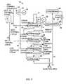
- FIG. 3illustrates a power plant that produces power by means of a steam turbine (ST), which can be single or multi-staged and an organic fluid turbine (OT) operating according to an organic Rankine cycle wherein the energy source is a geothermal fluid which has a relatively low liquid content.
- the power plant system generally designated by reference numeral 10is embodied by an open geothermal cycle represented by thick fluid lines wherein power producing geothermal fluid is delivered by production well 12 and rejected into injection well 15 , and a closed binary cycle represented by thin fluid lines wherein binary working fluid extracts heat from the geothermal fluid to produce power in the OT.
- Power plant system 10comprises separator 20 , steam turbine 30 , generator 32 coupled to ST 30 , vaporizer 35 , cascading preheaters 41 - 44 , condenser 46 , pump 47 , recuperator 49 , organic fluid turbine 50 , and generator 52 coupled to OT 50 .
- Geothermal fluid having a relatively low liquid contentis delivered in line 18 to separator 20 and is separated thereby into geothermal steam flowing in line 22 and geothermal liquid flowing in line 24 .
- the geothermal steambranches into lines 28 and 29 , and consequently is advantageously used to both produce power in ST 30 and to vaporize binary cycle working fluid, e.g. preferably pentane and isopentane, (hereinafter referred to as “working fluid”) so that the working fluid will produce power in OT 50 .
- working fluide.g. preferably pentane and isopentane
- the resulting geothermal steam condensateis delivered via line 36 to fourth-stage preheater 41 , and after its heat is transferred to the working fluid by means of preheater 41 , the discharged cooled geothermal steam condensate flows via line 39 to common conduit 55 .
- Geothermal liquid, on the other hand, flowing in line 24is delivered to third-stage preheater 42 and is discharged therefrom via line 39 to common conduit 55 .
- Low pressure steam from the exhaust of ST 30is delivered via line 56 to second-stage preheater 43 and is discharged therefrom as steam condensate, which is delivered via line 57 to common conduit 55 .
- the geothermal fluid discharged from preheaters 41 - 48is combined in common conduit 55 and is delivered to first-stage preheater 44 .
- the geothermal fluid discharged from preheater 44is then rejected into injection well 15 .
- OT 50exhausts heat depleted organic vapor, after work has been performed, via line 61 to recuperator 49 .
- the organic vaporexits recuperator 49 via line 63 and is delivered to condenser 46 , which condenses the vapor by means of a cooling fluid (not shown).
- Condensed working fluidis circulated by pump 47 through line 66 to recuperator 49 , which is adapted to transfer heat from the heat depleted organic vapor to the condensed working fluid, and then through line 67 to first-stage preheater 44 , from which the condensed working fluid is discharged via line 71 .
- Second-stage preheater 43third-stage preheater 42 , and fourth stage preheater 41 while the working fluid is discharged from these preheaters via lines 72 - 74 , respectively.
- Preheated working fluid exiting fourth stage preheater 41is supplied via line 74 to vaporizer 35 .
- Vaporized working fluid produced in vaporizer 35is delivered to OT 60 via line 77 .
- FIG. 3Ashows a similar embodiment of the invention described with reference to FIG. 3 but shows an example of the use of a multi-stage, here shown as a two stage steam turbine.
- intermediate pressure steamis extracted from an intermediate stage of ST 30 A and is delivered via line 64 A to preheater 43 ′A where it transfers heat contained therein to organic working fluid and is discharged therefrom as steam condensate, which is delivered via line 57 ′A to common conduit 55 A.
- the rest of the power plant as well as its operationis substantially identical to geothermal power plant system 10 , shown in FIG. 8 , and therefore for brevity need not be described.
- FIG. 4illustrates a temperature/heat diagram for power plant system 10 of FIG. 3 .
- This temperature/heat diagramis also applicable for the power plant system 10 A of FIG. 3A .
- a portion of a plurality of curves, each of which corresponds to a different heat transfer process of power plant system 10are shown in superimposed relation, to illustrate the reduced gap between corresponding points of the working fluid curve and one of the geothermal fluid curves with respect to the resulting gap of a prior art system shown in FIG. 2 .
- Curve 14represents the heat transfer rate of the working fluid, due to the heat influx by means of the preheaters and the vaporizer.
- Curve 99represents the heat influx to the working fluid from point S to point T as it passes through the recuperator, after being delivered thereto from the condenser.
- Curve 84represents the constant temperature heat transfer rate of geothermal steam from point H to point I which is realized by means of the heat transfer process carried out within the vaporizer.
- Curves 85 ′ and 86 ′represent the expansion of geothermal steam in the steam turbine, shown here illustratively as an example as a two-stage expansion of geothermal steam within the steam turbine, and curves 85 and 86 represent the corresponding low pressure steam that exits the steam at each of the two states, respectively, and which is delivered to the second-stage preheater.
- Curve 91represents the steam condensate which exits the vaporizer and which is delivered to the fourth-stage preheater.
- Curve 92represents the geothermal liquid or brine which is delivered to the third-stage preheater.
- Curve 96represents the steam condensate which exits the second-stage preheater and is mixed in the common conduit with the discharge from the third and fourth-stage preheaters, to be delivered to the first-stage preheater.
- gap G between point N of the working fluid curve 14 , and corresponding point O of the low pressure steam curve 85 exiting one stage of the steam turbineis dramatically less, approximately 10%, than the gap G′ of the prior art system shown in FIG. 2 between the same point N of the working fluid curve 14 and corresponding point O′.
- a gap indicative of the difference between heat efflux from the geothermal fluid and heat influx into the working fluidis graphically determined by constructing a horizontal line from a desired point of a curve.
- FIG. 5illustrates another embodiment of the invention wherein power plant system 110 produces power by means of organic fluid turbine 150 .
- the power plant systemis embodied by an open geothermal cycle represented by thick fluid lines wherein power producing geothermal fluid having a low liquid content is delivered by a production well and rejected into an injection well and a closed binary cycle represented by thin fluid lines wherein binary working fluid extracts heat from the geothermal fluid to produce power in turbine 150 .
- Power plant system 110comprises organic fluid turbine 160 , a generator (not shown) coupled to turbine 150 , vaporizer 135 , a third-stage process for preheating the working fluid that includes heater 142 and preheaters 141 and 143 , condenser 146 , pump 147 , and recuperator 149 .
- Geothermal steam flowing in line 129is delivered to vaporizer 135 and vaporizes preheated working fluid.
- the resulting geothermal steam condensateis delivered via line 136 to third-stage preheater 141 , and after its heat is transferred to the working fluid by means of preheater 141 , the discharged geothermal steam condensate flows via line 138 to first-stage preheater 143 , from which it is rejected into the injection well.
- Vaporized working fluidis delivered to OT 150 via line 117 .
- the exhaust from turbine 150is discharged through 160 .
- the turbine exhaust flowing through line 160is delivered to recuperator 149 , from which it exits via line 163 , is delivered to condenser 146 .
- Condensed working fluids which is condensed by means of cooling fluid 181is circulated by pump 147 via line 166 to recuperator 149 adapted to transfer heat from the organic vapor exhausted from OT 150 to the condensed working fluid, and then through line 167 to first-stage preheater 143 .
- the working fluidis heated in first-stage preheater 143 by the geothermal steam condensate flowing through line 138 , and is delivered via line 179 to second-stage heater 142 and then heated thereby by vapor extracted via the turbine bleed bled through line 155 , and thereafter is delivered via line 162 to third-stage preheater 141 and then heated thereby by the geothermal steam condensate exited from vaporizer 135 .
- the preheated working fluid exiting third-stage preheater 141is then delivered to vaporizer 135 via line 185 .
- Pump 190assists in circulating the condensed turbine bleed exiting heater 142 via lines 191 and 162 .
- FIG. 6illustrates a temperature/heat diagram for power plant system 110 of FIG. 5 .
- a plurality of curve portions, each of which correspond to a different heat transfer process of power plant system 110are shown in superimposed relation.
- Curve 187represents the heat transfer rate of the working fluid, due to the heat influx by means of the preheaters and the vaporizer.
- Curve 189represents the heat influx from working fluid expanded vapor to the working fluid condensate as it passes through the recuperator, after being delivered thereto from the condenser.
- Curve 198represents the constant-temperature heat influx from working fluid vapor (bled via line 155 from vapor turbine 150 ) to the working fluid as it passes through the heater.
- Curve 195represents the constant-temperature heat transfer rate of geothermal steam by means of the heat transfer process carried out within the vaporizer.
- Curve 196represents the steam condensate which exits the vaporizer and which is delivered to the third-stage preheater.
- Curve 198represents the geothermal liquid which can be used for pre-heating
- FIG. 7illustrates another embodiment of the invention wherein power plant system 210 produces power by means of two organic fluid turbines 252 and 254 , wherein turbine 252 is a high pressure turbine and turbine 254 is a low pressure turbine. Vaporized working fluid is delivered to high pressure turbine 252 via line 277 . The exhaust from high pressure turbine 252 is discharged through line 257 , and then branches to lines 261 and 262 . The turbine exhaust flowing through line 261 is delivered to the pressure turbine 254 , and the turbine exhaust flowing through line 262 is delivered to heater 242 . The remaining heat transfer means are identical to power plant system 110 and therefore for brevity need not be described.
- FIGS. 8-12illustrate another embodiment of the invention wherein the energy source for producing power with improved heat utilization is supplied by an industrial heat source such as industrial steam. Similar to the other embodiments of the invention, working fluid is vaporized by the steam to generate electricity and working fluid exiting the recuperator is preheated by turbine exhaust.
- industrial heat sourcesuch as industrial steam.
- industrial steam flowing through line 318is utilized to generate electricity by means of multistage steam turbine 330 having high pressure (HP) stage 331 , intermediate pressure (IP) stage 332 , and low pressure (LP) stage 333 .
- HPhigh pressure
- IPintermediate pressure
- LPlow pressure
- the industrial steam delivered to the inlet of multi-stage turbine 330 at a pressure of about 12 baris expanded in HP 337 to a pressure of about 5 bar, further expanded in IP 332 to about 8 bar, and additionally expanded in LP 333 to about 1.2 bar. Steam is bled off from each of these stages for preheating the working fluid.
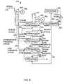
- FIG. 9illustrates a power plant generally designated by reference numeral 310 that produces power by means of a multistage steam turbine (ST) and an organic fluid turbine (OT) wherein the energy source is industrial steam.
- the power plant systemcomprises an open steam cycle (represented by thick fluid lines), wherein industrial steam is delivered through line 318 to ST 330 and cooled steam condensate is discharged through line 335 and a closed binary cycle (represented by thin fluid lines), wherein binary working fluid extracts heat from the industrial steam to produce power in the OT.
- Power plant system 310comprises multistage steam turbine 330 , electric generator 362 coupled to ST 330 , vaporizer 335 , cascading preheaters 341 - 344 , condenser 346 , pump 347 , recuperator 348 , organic fluid turbine 350 , and electric generator 352 coupled to OT 350 .
- Industrial steam delivered in line 318 to ST 330expands therein to produce power, and is bled from each stage of ST 330 to transfer heat to the working fluid so that the latter will produce power in OT 350 .
- Steam bled from the HP stage of ST 330is delivered via line 339 to vaporizer 335 and used to vaporize preheated working fluid.
- the resulting steam condensateis delivered via line 336 to fourth-stage preheater 341 , and after its heat is transferred to the working fluid by means of preheater 341 , the discharged cooled steam condensate flows via line 358 to common conduit 355 .
- Steam bled from the IP stage of ST 330is delivered via line 354 to third-stage preheater 342 and after its heat is transferred to the working fluid by means of preheater 342 , the discharged steam condensate flows therefrom via line 358 to common conduit 355 .
- Steam bled from the LP stage of ST 330is delivered via line 359 to second-stage preheater 343 and after its heat is transferred to the working fluid by means of preheater 343 , is discharged therefrom as steam condensate, which is delivered via line 357 to common conduit 355 .
- Fluid discharged from preheaters 341 - 343is mixed within common conduit 355 and is delivered to first-stage preheater, 344 via line 328 . After its heat is transferred to the working fluid by means of the preheater, the cooled steam condensate discharged from first-stage preheater 344 exits via line 385 .
- OT 350exhausts expanded organic vapor, after work has been performed, via line 361 to recuperator 349 .
- the heat depleted expanded organic vaporexits recuperator 349 via line 363 and is delivered to condenser 346 , which condenses the vapor by means of a cooling fluid (not shown).
- Working fluid condensateis circulated by pump 347 through line 366 to recuperate 349 , where heat is transferred from the expanded organic vapor to the working fluid condensate, and then through line 367 to first-stage preheater 344 , from which the preheated working fluid condensate is delivered via line 371 to second-stage preheater 343 .
- Additional heatis transferred to the preheated working fluid condensate by means of second-stage preheater 343 , third-stage preheater 342 , and fourth stage preheater 341 while the preheated working fluid condensate is discharged from these preheaters via lines 372 - 374 , respectively.
- Discharged preheated working fluid condensateis supplied via line 374 to vaporizer 335 and vaporized working fluid produced therein is delivered to OT 350 via line 377 .
- FIG. 10illustrates another embodiment of the invention wherein power plant system 410 having an industrial steam energy source comprises five cascading preheaters 440 - 444 for transferring heat from the steam bled from multistage steam turbine 480 to the working fluid.
- the industrial steam delivered through line 417branches into lines 418 and 419 , which extend to ST 430 and vaporizer 435 , respectively.
- Steam bled from the LP stage of ST 430is delivered via line 454 to third-stage preheater 442 and after its heat is transferred to the working fluid by means of preheater 442 , the steam condensate is discharged therefrom via line 458 to common conduit 455 .
- Steam bled from the LP stage of ST 430is delivered via line 459 to second-stage preheater 443 and, after its heat is transferred to the working fluid by means of preheater 443 , is discharged therefrom as steam condensate, which is delivered via line 457 to common conduit 455 .
- Fluid discharged from preheaters 440 - 443is mixed in common conduit 455 and is delivered to first-stage preheater 444 via line 428 .
- the cooled steam condensate discharged from first-stage preheater 444exits via line 485 .
- the remaining heat transfer meansare identical to power plant system 310 and therefore for brevity need not be described.
- FIGS. 9 and 10show three different outlets of steam turbine 330 or 430 for use of high, intermediate and low pressure steam in preheating the organic working fluid, usually two different outlets will suffice.
- FIG. 4Athe relevant temperature/heat diagram for the industrial embodiment shown and described with reference to FIG. 10 operating at two different pressure levels is actually FIG. 4A .
- industrial steam condensateprovides preheating of the organic working fluid as shown by curves 91 A, 95 A and 97 A.
- the remaining heat transfer processesare identical to geothermal power plant system 10 A, shown in FIG. 3A , and therefore for brevity need not be described.
- FIGS. 8-12for describing an embodiment of the invention wherein the energy source for producing power with improved heat utilization is supplied by an industrial heat source such as industrial steam
- an industrial energy sourcecan also be used in connection with the embodiments of the invention described with reference to FIGS. 5 and 7 .
- FIG. 6Apresents the relevant temperature/heat diagram for such an industrial application of the power plant.
- industrial steam condensateprovides preheating of the organic working fluid as shown by curve 196 A.
- the remaining heat transfer processesare identical to geothermal power plant system 110 and therefore for brevity need not be described.
Landscapes
- Engineering & Computer Science (AREA)
- Chemical & Material Sciences (AREA)
- Combustion & Propulsion (AREA)
- Mechanical Engineering (AREA)
- General Engineering & Computer Science (AREA)
- Engine Equipment That Uses Special Cycles (AREA)
Abstract
Description
Claims (13)
Priority Applications (7)
| Application Number | Priority Date | Filing Date | Title |
|---|---|---|---|
| US11/261,644US7775045B2 (en) | 2005-10-31 | 2005-10-31 | Method and system for producing power from a source of steam |
| US11/347,309US7797940B2 (en) | 2005-10-31 | 2006-02-06 | Method and system for producing power from a source of steam |
| NZ567843ANZ567843A (en) | 2005-10-31 | 2006-10-29 | Power from a source of steam with fluid extracted from one turbine delivered to preheating means |
| AU2006310083AAU2006310083B2 (en) | 2005-10-31 | 2006-10-29 | Method and system for producing power from a source of steam |
| PCT/IL2006/001239WO2007052257A2 (en) | 2005-10-31 | 2006-10-29 | Method and system for producing power from a source of steam |
| AT06809800TATE534819T1 (en) | 2005-10-31 | 2006-10-29 | METHOD AND SYSTEM FOR GENERATING ENERGY FROM A STEAM SOURCE |
| EP06809800AEP1943410B1 (en) | 2005-10-31 | 2006-10-29 | Method and system for producing power from a source of steam |
Applications Claiming Priority (1)
| Application Number | Priority Date | Filing Date | Title |
|---|---|---|---|
| US11/261,644US7775045B2 (en) | 2005-10-31 | 2005-10-31 | Method and system for producing power from a source of steam |
Related Child Applications (1)
| Application Number | Title | Priority Date | Filing Date |
|---|---|---|---|
| US11/347,309Continuation-In-PartUS7797940B2 (en) | 2005-10-31 | 2006-02-06 | Method and system for producing power from a source of steam |
Publications (2)
| Publication Number | Publication Date |
|---|---|
| US20070095065A1 US20070095065A1 (en) | 2007-05-03 |
| US7775045B2true US7775045B2 (en) | 2010-08-17 |
Family
ID=37994527
Family Applications (2)
| Application Number | Title | Priority Date | Filing Date |
|---|---|---|---|
| US11/261,644Expired - Fee RelatedUS7775045B2 (en) | 2005-10-31 | 2005-10-31 | Method and system for producing power from a source of steam |
| US11/347,309Active2029-01-20US7797940B2 (en) | 2005-10-31 | 2006-02-06 | Method and system for producing power from a source of steam |
Family Applications After (1)
| Application Number | Title | Priority Date | Filing Date |
|---|---|---|---|
| US11/347,309Active2029-01-20US7797940B2 (en) | 2005-10-31 | 2006-02-06 | Method and system for producing power from a source of steam |
Country Status (3)
| Country | Link |
|---|---|
| US (2) | US7775045B2 (en) |
| AT (1) | ATE534819T1 (en) |
| NZ (1) | NZ567843A (en) |
Cited By (12)
| Publication number | Priority date | Publication date | Assignee | Title |
|---|---|---|---|---|
| US20100281844A1 (en)* | 2009-05-05 | 2010-11-11 | Sholes Jr John Edward | Steam turbine power system and method of assembling the same |
| US20110219769A1 (en)* | 2010-12-20 | 2011-09-15 | Oleh Weres | Return carbon dioxide to flashed geothermal brine to control scale deposition in a geothermal power plant |
| US8601814B2 (en) | 2011-04-18 | 2013-12-10 | Ormat Technologies Inc. | Geothermal binary cycle power plant with geothermal steam condensate recovery system |
| US20150007565A1 (en)* | 2013-07-05 | 2015-01-08 | Ormat Technologies, Inc. | Method and apparatus for producing power from two geothermal heat sources |
| US20150284262A1 (en)* | 2013-03-15 | 2015-10-08 | Ormat Technologies, Inc. | System for processing brines |
| US9302681B2 (en) | 2011-08-12 | 2016-04-05 | Mcalister Technologies, Llc | Mobile transport platforms for producing hydrogen and structural materials, and associated systems and methods |
| US9388797B2 (en) | 2012-09-14 | 2016-07-12 | Ormat Technologies, Inc. | Method and apparatus for producing power from geothermal fluid |
| US9410535B2 (en) | 2011-10-03 | 2016-08-09 | Kabushiki Kaisha Toshiba | Binary power generation system |
| US9541284B2 (en) | 2010-02-13 | 2017-01-10 | Mcalister Technologies, Llc | Chemical reactors with annularly positioned delivery and removal devices, and associated systems and methods |
| USRE46316E1 (en)* | 2007-04-17 | 2017-02-21 | Ormat Technologies, Inc. | Multi-level organic rankine cycle power system |
| WO2020026022A1 (en)* | 2018-07-30 | 2020-02-06 | Ormat Technologies Inc. | System and method for increasing power output from an organic vapor turbine |
| US10794229B2 (en)* | 2017-02-08 | 2020-10-06 | Kobe Steel, Ltd. | Binary power generation system and stopping method for same |
Families Citing this family (36)
| Publication number | Priority date | Publication date | Assignee | Title |
|---|---|---|---|---|
| US8561405B2 (en)* | 2007-06-29 | 2013-10-22 | General Electric Company | System and method for recovering waste heat |
| US7866157B2 (en)* | 2008-05-12 | 2011-01-11 | Cummins Inc. | Waste heat recovery system with constant power output |
| US8341960B2 (en) | 2008-06-30 | 2013-01-01 | Ormat Technologies, Inc. | Multi-heat source power plant |
| US8850814B2 (en)* | 2009-06-11 | 2014-10-07 | Ormat Technologies, Inc. | Waste heat recovery system |
| US8544274B2 (en) | 2009-07-23 | 2013-10-01 | Cummins Intellectual Properties, Inc. | Energy recovery system using an organic rankine cycle |
| US8627663B2 (en) | 2009-09-02 | 2014-01-14 | Cummins Intellectual Properties, Inc. | Energy recovery system and method using an organic rankine cycle with condenser pressure regulation |
| US8276379B2 (en)* | 2009-11-16 | 2012-10-02 | General Electric Company | Systems and apparatus relating to solar-thermal power generation |
| IT1400467B1 (en)* | 2010-03-25 | 2013-06-11 | Nasini | PLANT FOR ENERGY PRODUCTION BASED ON THE RANKINE CYCLE WITH ORGANIC FLUID. |
| US20110271676A1 (en)* | 2010-05-04 | 2011-11-10 | Solartrec, Inc. | Heat engine with cascaded cycles |
| WO2012019161A1 (en) | 2010-08-05 | 2012-02-09 | Cummins Intellectual Properties, Inc. | Emissions-critical charge cooling using an organic rankine cycle |
| CN103180553B (en) | 2010-08-09 | 2015-11-25 | 康明斯知识产权公司 | Comprise Waste Heat Recovery System (WHRS) and the internal-combustion engine system of rankine cycle RC subtense angle |
| DE112011102675B4 (en) | 2010-08-11 | 2021-07-15 | Cummins Intellectual Property, Inc. | Split radiator structure for heat removal optimization for a waste heat recovery system |
| CN103180554B (en) | 2010-08-13 | 2016-01-20 | 康明斯知识产权公司 | Rankine Cycle Condenser Pressure Control Using Transducer Bypass Valve |
| US9217338B2 (en) | 2010-12-23 | 2015-12-22 | Cummins Intellectual Property, Inc. | System and method for regulating EGR cooling using a rankine cycle |
| US8826662B2 (en) | 2010-12-23 | 2014-09-09 | Cummins Intellectual Property, Inc. | Rankine cycle system and method |
| DE102012000100A1 (en) | 2011-01-06 | 2012-07-12 | Cummins Intellectual Property, Inc. | Rankine cycle-HEAT USE SYSTEM |
| WO2012096958A1 (en) | 2011-01-10 | 2012-07-19 | Cummins Intellectual Property, Inc. | Rankine cycle waste heat recovery system |
| EP3214296B1 (en) | 2011-01-20 | 2018-09-12 | Cummins Intellectual Properties, Inc. | Rankine cycle waste heat recovery system and method with improved egr temperature control |
| WO2012150994A1 (en) | 2011-02-28 | 2012-11-08 | Cummins Intellectual Property, Inc. | Engine having integrated waste heat recovery |
| ES2403550B1 (en)* | 2011-07-21 | 2014-09-08 | Universidade Da Coruña | ORGANIC RANKINE CYCLE REGENERATIVE OF QUASI-CRITICAL CONDENSATION. |
| US9671138B2 (en) | 2011-07-25 | 2017-06-06 | Ormat Technologies, Inc. | Cascaded power plant using low and medium temperature source fluid |
| US8667799B2 (en)* | 2011-07-25 | 2014-03-11 | Ormat Technologies Inc. | Cascaded power plant using low and medium temperature source fluid |
| US9341086B2 (en)* | 2011-07-25 | 2016-05-17 | Ormat Technologies, Inc. | Cascaded power plant using low and medium temperature source fluid |
| US8734546B2 (en)* | 2011-08-12 | 2014-05-27 | Mcalister Technologies, Llc | Geothermal energization of a non-combustion chemical reactor and associated systems and methods |
| US8893495B2 (en) | 2012-07-16 | 2014-11-25 | Cummins Intellectual Property, Inc. | Reversible waste heat recovery system and method |
| JP6013140B2 (en) | 2012-11-01 | 2016-10-25 | 株式会社東芝 | Power generation system |
| US9140209B2 (en) | 2012-11-16 | 2015-09-22 | Cummins Inc. | Rankine cycle waste heat recovery system |
| US9845711B2 (en) | 2013-05-24 | 2017-12-19 | Cummins Inc. | Waste heat recovery system |
| JP6188629B2 (en)* | 2013-05-24 | 2017-08-30 | 株式会社神戸製鋼所 | Binary power generator operation method |
| US9702270B2 (en)* | 2013-06-07 | 2017-07-11 | Her Majesty The Queen In Right Of Canada As Represented By The Minister Of Natural Resources | Hybrid Rankine cycle |
| US9869495B2 (en) | 2013-08-02 | 2018-01-16 | Martin Gordon Gill | Multi-cycle power generator |
| ITUA20163292A1 (en)* | 2016-05-10 | 2017-11-10 | Turboden Srl | MIXED OPTIMIZED FLOW TURBINE |
| ITUA20163869A1 (en)* | 2016-05-27 | 2017-11-27 | Turboden Srl | HIGH EFFICIENCY GEOTHERMAL TRACK SYSTEM |
| US10400652B2 (en)* | 2016-06-09 | 2019-09-03 | Cummins Inc. | Waste heat recovery architecture for opposed-piston engines |
| US10718236B2 (en)* | 2016-09-19 | 2020-07-21 | Ormat Technologies, Inc. | Turbine shaft bearing and turbine apparatus |
| WO2019130212A1 (en)* | 2017-12-28 | 2019-07-04 | Ormat Technologies Inc. | Air-cooled condenser configuration |
Citations (5)
| Publication number | Priority date | Publication date | Assignee | Title |
|---|---|---|---|---|
| US4041709A (en)* | 1973-06-22 | 1977-08-16 | Vereinigte Edelstahlwerke Aktiengesellschaft | Thermal power plants and method of operating a thermal power plant |
| US5664419A (en)* | 1992-10-26 | 1997-09-09 | Ormat Industries Ltd | Method of and apparatus for producing power using geothermal fluid |
| US5809782A (en)* | 1994-12-29 | 1998-09-22 | Ormat Industries Ltd. | Method and apparatus for producing power from geothermal fluid |
| US6009711A (en)* | 1997-08-14 | 2000-01-04 | Ormat Industries Ltd. | Apparatus and method for producing power using geothermal fluid |
| US6880344B2 (en)* | 2002-11-13 | 2005-04-19 | Utc Power, Llc | Combined rankine and vapor compression cycles |
- 2005
- 2005-10-31USUS11/261,644patent/US7775045B2/ennot_activeExpired - Fee Related
- 2006
- 2006-02-06USUS11/347,309patent/US7797940B2/enactiveActive
- 2006-10-29ATAT06809800Tpatent/ATE534819T1/enactive
- 2006-10-29NZNZ567843Apatent/NZ567843A/enunknown
Patent Citations (5)
| Publication number | Priority date | Publication date | Assignee | Title |
|---|---|---|---|---|
| US4041709A (en)* | 1973-06-22 | 1977-08-16 | Vereinigte Edelstahlwerke Aktiengesellschaft | Thermal power plants and method of operating a thermal power plant |
| US5664419A (en)* | 1992-10-26 | 1997-09-09 | Ormat Industries Ltd | Method of and apparatus for producing power using geothermal fluid |
| US5809782A (en)* | 1994-12-29 | 1998-09-22 | Ormat Industries Ltd. | Method and apparatus for producing power from geothermal fluid |
| US6009711A (en)* | 1997-08-14 | 2000-01-04 | Ormat Industries Ltd. | Apparatus and method for producing power using geothermal fluid |
| US6880344B2 (en)* | 2002-11-13 | 2005-04-19 | Utc Power, Llc | Combined rankine and vapor compression cycles |
Cited By (17)
| Publication number | Priority date | Publication date | Assignee | Title |
|---|---|---|---|---|
| USRE46316E1 (en)* | 2007-04-17 | 2017-02-21 | Ormat Technologies, Inc. | Multi-level organic rankine cycle power system |
| US8250848B2 (en)* | 2009-05-05 | 2012-08-28 | General Electric Company | Steam turbine power system and method of assembling the same |
| US20100281844A1 (en)* | 2009-05-05 | 2010-11-11 | Sholes Jr John Edward | Steam turbine power system and method of assembling the same |
| US9541284B2 (en) | 2010-02-13 | 2017-01-10 | Mcalister Technologies, Llc | Chemical reactors with annularly positioned delivery and removal devices, and associated systems and methods |
| US20110219769A1 (en)* | 2010-12-20 | 2011-09-15 | Oleh Weres | Return carbon dioxide to flashed geothermal brine to control scale deposition in a geothermal power plant |
| US8276381B2 (en)* | 2010-12-20 | 2012-10-02 | Chemtreat, Inc. | Return carbon dioxide to flashed geothermal brine to control scale deposition in a geothermal power plant |
| US8601814B2 (en) | 2011-04-18 | 2013-12-10 | Ormat Technologies Inc. | Geothermal binary cycle power plant with geothermal steam condensate recovery system |
| US9302681B2 (en) | 2011-08-12 | 2016-04-05 | Mcalister Technologies, Llc | Mobile transport platforms for producing hydrogen and structural materials, and associated systems and methods |
| US9410535B2 (en) | 2011-10-03 | 2016-08-09 | Kabushiki Kaisha Toshiba | Binary power generation system |
| US9388797B2 (en) | 2012-09-14 | 2016-07-12 | Ormat Technologies, Inc. | Method and apparatus for producing power from geothermal fluid |
| US9403694B2 (en)* | 2013-03-15 | 2016-08-02 | Ormat Technologies, Inc. | System for processing brines |
| US20150284262A1 (en)* | 2013-03-15 | 2015-10-08 | Ormat Technologies, Inc. | System for processing brines |
| US20150007565A1 (en)* | 2013-07-05 | 2015-01-08 | Ormat Technologies, Inc. | Method and apparatus for producing power from two geothermal heat sources |
| US9920749B2 (en)* | 2013-07-05 | 2018-03-20 | Ormat Technologies, Inc. | Method and apparatus for producing power from two geothermal heat sources |
| US10794229B2 (en)* | 2017-02-08 | 2020-10-06 | Kobe Steel, Ltd. | Binary power generation system and stopping method for same |
| WO2020026022A1 (en)* | 2018-07-30 | 2020-02-06 | Ormat Technologies Inc. | System and method for increasing power output from an organic vapor turbine |
| US11542837B2 (en)* | 2018-07-30 | 2023-01-03 | Ormat Technologies Inc. | System and method for increasing power output from an organic vapor turbine |
Also Published As
| Publication number | Publication date |
|---|---|
| US20070095066A1 (en) | 2007-05-03 |
| US20070095065A1 (en) | 2007-05-03 |
| US7797940B2 (en) | 2010-09-21 |
| ATE534819T1 (en) | 2011-12-15 |
| NZ567843A (en) | 2011-06-30 |
Similar Documents
| Publication | Publication Date | Title |
|---|---|---|
| US7775045B2 (en) | Method and system for producing power from a source of steam | |
| US9388797B2 (en) | Method and apparatus for producing power from geothermal fluid | |
| CN102084093B (en) | Method for operating a thermodynamic cycle, and thermodynamic cycle | |
| KR940002718B1 (en) | Direct fired power cycle | |
| EP2580435B1 (en) | Orc plant with a system for improving the heat exchange between the source of hot fluid and the working fluid | |
| US6968690B2 (en) | Power system and apparatus for utilizing waste heat | |
| Singh et al. | Thermoeconomic evaluation and optimization of a Brayton–Rankine–Kalina combined triple power cycle | |
| CN1100933C (en) | Converting heat into useful energy | |
| EP2440751B1 (en) | Waste heat recovery system | |
| US5664419A (en) | Method of and apparatus for producing power using geothermal fluid | |
| EP3242994B1 (en) | Multi-pressure organic rankine cycle | |
| EP3464836B1 (en) | High efficiency binary geothermal system | |
| US8601814B2 (en) | Geothermal binary cycle power plant with geothermal steam condensate recovery system | |
| MX2008014558A (en) | A method and system for generating power from a heat source. | |
| KR19990082915A (en) | Method of heating gas turbine fuel in a combined cycle power plant using multi-component flow mixtures | |
| CN102575531A (en) | Method and system for generating high pressure steam | |
| US8474262B2 (en) | Advanced tandem organic rankine cycle | |
| US6519927B2 (en) | Method for operating a combined cycle power plant, and combined cycle power plant | |
| US20120324885A1 (en) | Geothermal power plant utilizing hot geothermal fluid in a cascade heat recovery apparatus | |
| EP1943410B1 (en) | Method and system for producing power from a source of steam | |
| NO338183B1 (en) | PREVENTMATE AG AG DEVICE FOR UTILIZATION OF PLASTIC HEAT | |
| KR101289187B1 (en) | Apparatus for converting thermal energy | |
| Mikielewicz | Utilisation of bleed steam from power plant to increase saturation temperature in organic Rankine cycle | |
| RU2560612C1 (en) | Heat power plant operation mode | |
| RU2562725C1 (en) | Utilisation method of thermal energy generated by thermal power plant |
Legal Events
| Date | Code | Title | Description |
|---|---|---|---|
| AS | Assignment | Owner name:ORMAT TECHNOLOGIES, INC., NEVADA Free format text:ASSIGNMENT OF ASSIGNORS INTEREST;ASSIGNORS:KAPLAN, URI;KRIEGER, ZVI;REEL/FRAME:017570/0696 Effective date:20060129 | |
| AS | Assignment | Owner name:ORAMT TECHNOLOGIES INC., NEVADA Free format text:CORPORATE ADDRESS CHANGE;ASSIGNOR:ORMAT TECHNOLOGIES INC.;REEL/FRAME:020082/0437 Effective date:20060414 Owner name:ORMAT TECHNOLOGIES INC., NEVADA Free format text:CORPORATE ADDRESS CHANGE;ASSIGNOR:ORMAT TECHNOLOGIES INC.;REEL/FRAME:020082/0437 Effective date:20060414 | |
| STCF | Information on status: patent grant | Free format text:PATENTED CASE | |
| FPAY | Fee payment | Year of fee payment:4 | |
| MAFP | Maintenance fee payment | Free format text:PAYMENT OF MAINTENANCE FEE, 8TH YEAR, LARGE ENTITY (ORIGINAL EVENT CODE: M1552) Year of fee payment:8 | |
| FEPP | Fee payment procedure | Free format text:MAINTENANCE FEE REMINDER MAILED (ORIGINAL EVENT CODE: REM.); ENTITY STATUS OF PATENT OWNER: LARGE ENTITY | |
| LAPS | Lapse for failure to pay maintenance fees | Free format text:PATENT EXPIRED FOR FAILURE TO PAY MAINTENANCE FEES (ORIGINAL EVENT CODE: EXP.); ENTITY STATUS OF PATENT OWNER: LARGE ENTITY | |
| STCH | Information on status: patent discontinuation | Free format text:PATENT EXPIRED DUE TO NONPAYMENT OF MAINTENANCE FEES UNDER 37 CFR 1.362 | |
| FP | Lapsed due to failure to pay maintenance fee | Effective date:20220817 |