US7774046B2 - Magnetic navigation system - Google Patents
Magnetic navigation systemDownload PDFInfo
- Publication number
- US7774046B2 US7774046B2US10/799,358US79935804AUS7774046B2US 7774046 B2US7774046 B2US 7774046B2US 79935804 AUS79935804 AUS 79935804AUS 7774046 B2US7774046 B2US 7774046B2
- Authority
- US
- United States
- Prior art keywords
- magnet units
- magnet
- magnets
- operating region
- magnetic field
- Prior art date
- Legal status (The legal status is an assumption and is not a legal conclusion. Google has not performed a legal analysis and makes no representation as to the accuracy of the status listed.)
- Active, expires
Links
- 238000000034methodMethods0.000claimsabstractdescription26
- 238000003384imaging methodMethods0.000claimsdescription30
- 238000013178mathematical modelMethods0.000claims1
- 230000005415magnetizationEffects0.000description12
- 238000010586diagramMethods0.000description4
- 239000000696magnetic materialSubstances0.000description3
- 229910021417amorphous siliconInorganic materials0.000description2
- 150000001875compoundsChemical class0.000description2
- 238000010276constructionMethods0.000description2
- 230000000694effectsEffects0.000description2
- XAGFODPZIPBFFR-UHFFFAOYSA-NaluminiumChemical compound[Al]XAGFODPZIPBFFR-UHFFFAOYSA-N0.000description1
- 229910052782aluminiumInorganic materials0.000description1
- 229940079593drugDrugs0.000description1
- 239000003814drugSubstances0.000description1
- 208000014674injuryDiseases0.000description1
- 238000004519manufacturing processMethods0.000description1
- 238000011084recoveryMethods0.000description1
- 125000006850spacer groupChemical group0.000description1
- 238000001356surgical procedureMethods0.000description1
- 230000008733traumaEffects0.000description1
Images


Classifications
- A—HUMAN NECESSITIES
- A61—MEDICAL OR VETERINARY SCIENCE; HYGIENE
- A61B—DIAGNOSIS; SURGERY; IDENTIFICATION
- A61B90/00—Instruments, implements or accessories specially adapted for surgery or diagnosis and not covered by any of the groups A61B1/00 - A61B50/00, e.g. for luxation treatment or for protecting wound edges
- A61B90/10—Instruments, implements or accessories specially adapted for surgery or diagnosis and not covered by any of the groups A61B1/00 - A61B50/00, e.g. for luxation treatment or for protecting wound edges for stereotaxic surgery, e.g. frame-based stereotaxis
- A—HUMAN NECESSITIES
- A61—MEDICAL OR VETERINARY SCIENCE; HYGIENE
- A61B—DIAGNOSIS; SURGERY; IDENTIFICATION
- A61B34/00—Computer-aided surgery; Manipulators or robots specially adapted for use in surgery
- A61B34/70—Manipulators specially adapted for use in surgery
- A—HUMAN NECESSITIES
- A61—MEDICAL OR VETERINARY SCIENCE; HYGIENE
- A61B—DIAGNOSIS; SURGERY; IDENTIFICATION
- A61B34/00—Computer-aided surgery; Manipulators or robots specially adapted for use in surgery
- A61B34/70—Manipulators specially adapted for use in surgery
- A61B34/73—Manipulators for magnetic surgery
- A61B2034/731—Arrangement of the coils or magnets
- A61B2034/732—Arrangement of the coils or magnets arranged around the patient, e.g. in a gantry
- A—HUMAN NECESSITIES
- A61—MEDICAL OR VETERINARY SCIENCE; HYGIENE
- A61B—DIAGNOSIS; SURGERY; IDENTIFICATION
- A61B6/00—Apparatus or devices for radiation diagnosis; Apparatus or devices for radiation diagnosis combined with radiation therapy equipment
- A61B6/12—Arrangements for detecting or locating foreign bodies
- A—HUMAN NECESSITIES
- A61—MEDICAL OR VETERINARY SCIENCE; HYGIENE
- A61B—DIAGNOSIS; SURGERY; IDENTIFICATION
- A61B90/00—Instruments, implements or accessories specially adapted for surgery or diagnosis and not covered by any of the groups A61B1/00 - A61B50/00, e.g. for luxation treatment or for protecting wound edges
- A61B90/36—Image-producing devices or illumination devices not otherwise provided for
- A61B90/361—Image-producing devices, e.g. surgical cameras
Definitions
- This inventionrelates to methods and apparatus for magnetically navigating magnetically responsive medical devices in an operating region in a subject.
- Magnetic navigation of medical devicesprovides fast, simple, and reliable navigation in a subject's body. With the reduced size and increase flexibility of magnetically responsive medical devices, magnetically navigated devices can reach parts of the subjects body that could not be reached with most previously available remote navigation techniques.
- Magnetic navigationrelies upon external source magnets, either electromagnets, or more recently permanent magnets, to provide a controllable magnetic field in an operating region in a subject to orient a magnetically responsive device in the operating region.
- a challenge for magnetic navigationis to position the magnet sufficient close to the patient to provide a sufficiently strong field for magnetic navigation, while accommodating patients of varying sizes, leaving room for other medical equipment (particularly imaging equipment), and provide access to the patient.
- the apparatus and method of this inventionemploy at least two magnet units movably mounted adjacent (and preferably on opposite sides of) an operating region in a subject for coordinated movement about the operating region.
- Each magnet unitcomprises a magnet and a positioner for changing the position of the magnet, and thus the direction of the magnetic field that the magnet applies to the operating region.
- the magnetsare mounted for coordinated movement about the operating region, so that the magnet units can be positioned close to the operating region, yet be moved out of the way to positions where they still apply a magnetic field to the operating region, when necessary for example to accommodate imaging equipment.
- the systempreferably includes a controller for operating the positioners to maintain the magnetic field direction as the magnet units are moved.
- the inventionprovides a simple, relatively inexpensive way of applying a magnetic field in a selected direction.
- the capability of positioning the magnet units close to the operating regionallows the magnets to be made smaller and more compact, which in turn means that the positioners can be smaller and less expensive.
- the smaller, more compact size of the magnetsmeans that they interfere less with access to the patient by medical equipment or personnel, and the ability to move the magnet unit around the operating region allows the magnets to moved out of the way when needed, while still maintaining a magnetic field in the operating region.
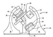
- FIG. 1is a front elevation view of a first embodiment of a magnetic navigation system constructed according to the principles of this invention
- FIG. 2is a rear elevation view of the magnetic navigation system of the first embodiment
- FIG. 3is a side elevation view of the magnetic navigation system of the first embodiment
- FIG. 4is a front perspective view of the magnetic navigation system of the first embodiment
- FIG. 5is a front elevation view of a second embodiment of a magnetic navigation system constructed according to the principles of this invention.
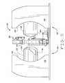
- FIG. 6is a front perspective view of the magnetic navigation system of the second embodiment
- FIG. 7is a rear perspective view of the magnetic navigation system of the second embodiment
- FIG. 8is a front perspective view of the magnetic navigation system of the second embodiment, with the imaging C-arm rotated 28°;
- FIG. 9is a front elevation view of the magnetic navigation system of the second embodiment, with the imaging C-arm rotated 30°, and the magnet units rotated to accommodate the C-arm;
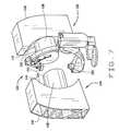
- FIG. 10is a perspective view of a magnet adapted for use in the magnet units of some embodiments of this invention.
- FIG. 11is a perspective view of a backing plate for a the magnet
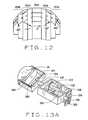
- FIG. 12is a top plan view of the magnet
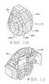
- FIG. 13Ais a perspective view of a positioner adapted for use in the magnet units of some embodiments of this invention.
- FIG. 13Bis a perspective view of the positioner
- FIG. 13Cis a plan view of the positioner
- FIG. 14Ais a diagram illustrating the positioning of magnets on opposites sides of a patient in the lateral plane
- FIG. 14Bis a diagram illustrating the positioning of magnets on opposite sides of a patient, rotated 30° in the transverse plane;
- FIG. 14Cis a diagram illustrating the positioning of magnets on opposite sides of a patient, rotated 45° in the transverse plane.
- FIG. 14Dis a diagram illustrating the positioning of magnets on opposite sides of a patient, rotated 60° in the transverse plane.
- a first embodiment of a magnetic navigation system constructed according to the principles of this inventionis indicated generally as 20 in FIGS. 1-4 .
- the system 20is adapted to apply a magnetic field of selected direction to an operating region in subject on a subject support (not shown) in the magnetic navigation system.
- the system 20broadly comprises at least two magnet units 22 and 24 mounted on a support 26 adjacent (and preferably on opposite sides of) the operating region, for coordinated rotational movement about the operating region.
- the systemalso includes an imaging system 28 for imaging the operating region.
- the magnet units 22 and 24each comprise a compound permanent magnet 30 comprising a plurality of segments of magnetic material with differing magnetization directions so that relatively small rotations or pivots change the magnetic field projected by the magnet at a specific point.
- Each of the magnet units 22 and 24also comprise a positioner 32 for controlling the position of the magnet 30 , e.g. for rotating the magnet 30 about a first axis and pivoting the magnet 30 about a second axis, to selectively change the magnetic field applied by each magnet to the operating region in a subject on the subject support.
- the magnet units 22 and 24are mounted on opposite sides of the operating region.
- the first axis of rotation of each magnetpreferably extends through the respective magnet and the operating region, and preferably the first axes of rotation of the magnets are co-linear.
- the second axes of pivoting of each magnetis preferably perpendicular to the first axis, and also rotates about the first axis.
- Each magnet unit 22 and 24comprises a cover 36 .
- the coverprotects the patient and medical personnel and equipment from the movement of the magnets 30 , it hides the movement to prevent patient concern over the operation of the system, and it improves the aesthetics of the system.
- the magnet units 22 and 24are mounted on opposite sides of the operating region on support 26 .
- This supportcan be any support that accommodates the coordinated movement of the magnet units 22 and 24 about the operating region.
- One possible configuration for support 26is shown in FIGS. 1-4 , where the support comprises two stanchions 38 and 40 , having arcuate surfaces 38 and 40 on which the magnet units 22 and 24 can travel as they rotate about the operating region.
- the surfaces 40 and 42can be the arcs of a circle, but could take some other shape so that the distance between the magnet units and the operating region changes as the magnet units rotate about the operating region on the stanchions 38 and 40 .
- the surfaces 42 and 44could be shaped so that the magnet units are closer to the operating region when they are above the plane of the subject.
- Any drive mechanismcan be used to move the magnet units 22 and 24 on the stanchions 38 and 40 .
- the magnet units 22 and 24could be fixed relative to the support, and it could be the support that moves to rotate the magnet units 22 and 24 about the operating.
- the rotation of the magnet units about the operating regioncould be accomplished by a combination of movement of the magnet units relative to the support, and movement of the support relative to the subject.
- the system 20also includes an imaging system 28 for imaging the operating region.
- the imaging systempreferably includes some type of C-arm structure 50 , or some other movable support that allows the imaging equipment to be repositioned about the operating region to allow imaging from the most advantageously angle. For most procedures in the chest, medical personnel are used to have left anterior oblique (lao) and right anterior oblique (rao) images, and the support is preferably capable of moving the imaging equipment to provide these images.
- the imaging system 28preferably also includes a imaging beam source 52 and an imaging beam receiver 44 , such as an amorphous silicon plate.
- the source 52 and receiver 54are preferably constructed to be immune to, or are shielded from the effects of, the magnets 30 in the magnet units 22 and 24 .
- a controlis preferably provided to control the positioners 32 of each magnet unit 22 and 24 , to cause the magnets 30 to move to provide a magnetic field in a selected direction in the operating region.
- An interfacecan be provided to allow the user to identify a selected magnet field direction, and the controller operates the positioners 32 to position the magnets to achieve the desired magnetic field direction.
- the interfacemight allow the user to select a desired medical device orientation, and the controller operates the positioners 32 to position the magnets to achieve the magnetic field direction to achieve the desired medical device orientation.
- the controllermay take into account the physically properties of the device, represented in either a look-up table or in a set of equations, or parameters for equations, to determine the field to cause the device to align in the selected direction.
- the controllermight also take into account the field strength applied in the operating region.
- the field strengthis relatively constant, however in some embodiments of the present invention, in order to reduce magnet size, and facilitate movement of the magnet units, the field strength might vary depending upon the position of the magnet units. Thus the desired field direction to attain a given device orientation might vary depending upon the position of the magnet units.
- the controllerdetermines and applies the field based upon the desired orientation of the medical device input by the user, and upon the strength of the field that the magnets apply in their current position. The controller could also indicate to the user that it would be advantageous to reposition the magnets to achieve a higher field strength.
- a second embodiment of a magnetic navigation system constructed according to the principles of this inventionis indicated generally as 120 in FIGS. 5-8 .
- the system 120is adapted to apply a magnetic field of selected direction to an operating region in subject on a subject support (not shown) in the magnetic navigation system.
- the system 120broadly comprises at least two magnet units 122 and 124 mounted on a support 126 on opposite sides of the operating region, for coordinated rotational movement about the operating region.
- the systemalso includes an imaging system 128 for imaging the operating region.
- the magnet units 122 and 124each comprise a compound permanent magnet 30 comprising a plurality of segments of magnetic material with differing magnetization directions so that relatively small rotations or pivots change the magnetic field projected by the magnet at a specific point.
- Each of the magnet units 122 and 124also comprise a positioner 132 for controlling the position of the magnet 30 , e.g. for rotating the magnet 30 about a first axis and pivoting the magnet 30 about a second axis, to selectively change the magnetic field applied by each magnet to the operating region in a subject on the subject support.
- the magnet units 122 and 124are mounted on opposite sides of the operating region.
- the first axis of rotation of each magnetpreferably extend through the respective magnet and the operating region, and preferably the first axes of rotation of the magnets are co-linear.
- the second axes of pivoting of each magnetis preferably perpendicular to the first axis, and rotates about the first axis.
- Each magnet unit 122 and 124comprises a cover 136 , the cover protects the patient and medical personnel and equipment from the movement of the magnets 130 , it hides the movement to prevent patient concern over the operation of the system, and it improves the aesthetics of the system.
- the magnet units 122 and 124are mounted on opposite sides of the operating region on support 126 .
- This supportcan be any support that accommodates the coordinated movement of the magnet units 122 and 124 about the operating region.
- One possible configuration for support 126is shown in FIGS.
- the supportcomprises two stanchions 138 and 140 , having arcuate surfaces 142 and 144 on which the magnet units 122 and 124 can travel as they rotate about the operating region.
- the surfaces 142 and 144can be the arcs of a circle, but could take some other shape so that the distance between the magnet units and the operating region changes as the magnet units rotate about the operating region on the stanchions 138 and 140 .
- the surfaces 142 and 144could be shaped so that the magnet units 122 and 124 are closer to the operating region when they are above the plane of the subject. Any drive mechanism can be used to move the magnet units 122 and 124 on the stanchions 134 and 136 .
- the magnet units 122 and 124could be fixed relative to the support, and it could be the support that moves to rotate the magnet units 122 and 124 about the operating.
- the rotation of the magnet units about the operating regioncould be accomplished by a combination of movement of the magnet units relative to the support, and movement of the support relative to the subject.
- the system 120also includes an imaging system 128 for imaging the operating region.
- the imaging systempreferably includes some type of C-arm structure 150 , or some other movable support that allows the imaging equipment to be repositioned about the operating region to allow imaging from the most advantageously angle. For most procedures in the chest, medical personnel are used to have left anterior oblique (lao) and right anterior oblique (rao) images, and the support is preferably capable of moving the imaging equipment to provide these images.
- the imaging system 128preferably also includes a imaging beam source 152 and an imaging beam receiver 154 , such as an amorphous silicon plate.
- the source 152 and receiver 154are preferably constructed to be immune to, or are shielded from the effects of, the magnets 30 in the magnet units 122 and 124 .
- a controlis preferably provided to control the positioners 132 of each magnet unit 122 and 124 , to cause the magnets to move to provide a magnetic field in a selected direction.
- An interfacecan be provided to allow the users to identify a selected magnet field direction, and the controller operates the positioners 132 to position the magnets to achieve the desired magnetic field direction.
- the interfacemight allow the user to select a desired device orientation, and the controller operates the positioners 132 to position the magnets to achieve the desired magnetic field direction to achieve the desired device orientation.
- the controllermay take into account the physically properties of the device, represented in either a look-up table or in a set of equations, or parameters for equations, to determine the field to cause the device to align in the selected direction.
- the controllermight also take into account the field strength applied in the operating region.
- the field strengthis relatively constant, however in some embodiments of the present invention, in order to reduce magnet size, and facilitate movement of the magnet units, the field strength might vary depending upon the position of the magnet units. Thus the desired field direction to attain a given device orientation might vary depending upon the position of the magnet units.
- the controllerdetermines and applies the field based upon the desired orientation of the medical device input by the user, and upon the strength of the field that the magnets apply in their current position. The controller could also indicate to the user that it would be advantageous to reposition the magnets to achieve a higher field strength.
- the magnet used in the embodiments of this inventionpreferably comprises an aluminum backing plate 200 , having a plurality of spacer blocks 202 thereon ( FIG. 11 ) for mounting blocks 204 of magnetic material.
- the blocks 204are sized, shaped, and positioned, and have a magnetization direction to control the magnetic field strength projected by the assembled magnet into the operating region.
- the blocks 204 ahave a magnetization direction of +60° relative to the horizontal axis of the blocks
- the blocks 204 bhave a magnetization direction of +30° relative to the horizontal axis of the blocks
- the blocks 204 chave a magnetization direction of 0° relative to the horizontal axis
- blocks 204 dhave a magnetization direction of ⁇ 30° relative to the horizontal axis of the blocks
- the blocks 204 ehave a magnetization direction of ⁇ 60° relative to the horizontal axis.
- the blocksare preferably sized, shaped and positioned generally as taught in co-pending application Ser. No. 10/056,227, filed Jan. 23, 2002, for Rotating and Pivoting Magnet for Magnetic Navigation; and application Ser. No.
- FIGS. 13A-13CA positioner 132 adapted for use in some embodiments of the magnetic navigation system of this invention is shown in FIGS. 13A-13C .
- the magnet 30is pivotally mounted between the legs of a generally U-shaped bracket 302 .
- a motor 304is mounted on the base of the U-shaped bracket, to drive a gear box 306 also mounted on the base of the U-shaped bracket.
- the gear box 306drives a cable 308 connected to the magnet 30 , so that the motor 304 can move the magnet about its pivotal mounting.
- a shaft 310extends from the bottom of the U-shaped bracket 302 , and is rotatably mounted in a box-shaped frame 312 .
- a drive motor 314drives a sheave 316 which drives a belt 318 that drives a sheave 320 on the shaft 310 , to rotate the shaft, and thus the magnet 30 .
- the positioner 132in addition to rotating the magnet about a first axis, and pivoting the magnet about a second, perpendicular axis, the positioner 132 also translates the magnet in a direction generally parallel to the axis of rotation.
- the positioner 132includes a guide rod 322 , carriage 324 slidably mounted on the guide rod 322 , and driven by a lead screw 326 .
- the lead screw 326has a sheave 328 thereon, and is driven by a belt 330 driven by sheave 332 on motor 334 .
- the positionerneed not be able to translate the magnet, and can merely rotate and pivot the magnet.
- the rotating movement of the magnet unitsalso allows the magnet units to be positioned closer to the operating region.
- the magnetswhen the magnets are disposed in the plane of the patient, the magnets must be spaced sufficiently to accommodate the entire width of the patient. To accommodate most patients, this distance would be a minimum of 27 inches (about 69 cm), which would mean the distance to the center of the patient is 13.5 inches (about 34 cm).
- the magnet unitsare rotated in the transverse plane 30°, at least one of the magnets can be moved closer to the operating region.
- the magnet unit above the plane of the patientcan be moved to a distance of about 11.38 inches (about 29 cm) from the center of the patient. If as shown in FIG. 14C , the magnet units are rotated in the transverse plane 45°, at least one of the magnets can be moved closer to the operating region. The magnet unit above the plane of the patient can be moved to a distance of about 9.57 inches (about 24 cm) from the center of the patient. If as shown in FIG. 14D , the magnet units are rotated in the transverse plane 60°, at least one of the magnets can be moved closer to the operating region. The magnet unit above the plane of the patient can be moved to a distance of about 7.60 inches (about 19 cm) from the center of the patient.
- the ability to move the magnet unitsallows the magnet units to be placed closer to the patient, allowing smaller magnets to be used.
- the magnetscan be moved out of the way, while maintaining the magnetic field in the same direction (or in some preferred embodiments, adjusting the magnetic field direction to accommodating the changing field strength in the operating region).
Landscapes
- Health & Medical Sciences (AREA)
- Surgery (AREA)
- Life Sciences & Earth Sciences (AREA)
- Engineering & Computer Science (AREA)
- Heart & Thoracic Surgery (AREA)
- Biomedical Technology (AREA)
- Nuclear Medicine, Radiotherapy & Molecular Imaging (AREA)
- Medical Informatics (AREA)
- Molecular Biology (AREA)
- Animal Behavior & Ethology (AREA)
- General Health & Medical Sciences (AREA)
- Public Health (AREA)
- Veterinary Medicine (AREA)
- Robotics (AREA)
- Pathology (AREA)
- Oral & Maxillofacial Surgery (AREA)
- Magnetic Resonance Imaging Apparatus (AREA)
Abstract
Description
Claims (15)
Priority Applications (1)
| Application Number | Priority Date | Filing Date | Title |
|---|---|---|---|
| US10/799,358US7774046B2 (en) | 2003-03-13 | 2004-03-12 | Magnetic navigation system |
Applications Claiming Priority (2)
| Application Number | Priority Date | Filing Date | Title |
|---|---|---|---|
| US45441003P | 2003-03-13 | 2003-03-13 | |
| US10/799,358US7774046B2 (en) | 2003-03-13 | 2004-03-12 | Magnetic navigation system |
Publications (2)
| Publication Number | Publication Date |
|---|---|
| US20040249262A1 US20040249262A1 (en) | 2004-12-09 |
| US7774046B2true US7774046B2 (en) | 2010-08-10 |
Family
ID=33493086
Family Applications (1)
| Application Number | Title | Priority Date | Filing Date |
|---|---|---|---|
| US10/799,358Active2027-09-28US7774046B2 (en) | 2003-03-13 | 2004-03-12 | Magnetic navigation system |
Country Status (1)
| Country | Link |
|---|---|
| US (1) | US7774046B2 (en) |
Cited By (17)
| Publication number | Priority date | Publication date | Assignee | Title |
|---|---|---|---|---|
| US7961926B2 (en) | 2005-02-07 | 2011-06-14 | Stereotaxis, Inc. | Registration of three-dimensional image data to 2D-image-derived data |
| US8308628B2 (en) | 2009-11-02 | 2012-11-13 | Pulse Therapeutics, Inc. | Magnetic-based systems for treating occluded vessels |
| US8369934B2 (en) | 2004-12-20 | 2013-02-05 | Stereotaxis, Inc. | Contact over-torque with three-dimensional anatomical data |
| US9156169B2 (en) | 2012-04-04 | 2015-10-13 | Ankon Technologies Co., Ltd. | System and method for orientation and movement of remote objects |
| US9339285B2 (en) | 2013-03-12 | 2016-05-17 | Levita Magnetics International Corp. | Grasper with magnetically-controlled positioning |
| US9844391B2 (en) | 2009-02-06 | 2017-12-19 | Levita Magnetics International Corp. | Remote traction and guidance system for mini-invasive surgery |
| US9883878B2 (en) | 2012-05-15 | 2018-02-06 | Pulse Therapeutics, Inc. | Magnetic-based systems and methods for manipulation of magnetic particles |
| US10010370B2 (en) | 2013-03-14 | 2018-07-03 | Levita Magnetics International Corp. | Magnetic control assemblies and systems therefor |
| US10537348B2 (en) | 2014-01-21 | 2020-01-21 | Levita Magnetics International Corp. | Laparoscopic graspers and systems therefor |
| US10537713B2 (en) | 2009-05-25 | 2020-01-21 | Stereotaxis, Inc. | Remote manipulator device |
| US10905511B2 (en) | 2015-04-13 | 2021-02-02 | Levita Magnetics International Corp. | Grasper with magnetically-controlled positioning |
| US11020137B2 (en) | 2017-03-20 | 2021-06-01 | Levita Magnetics International Corp. | Directable traction systems and methods |
| US11413025B2 (en) | 2007-11-26 | 2022-08-16 | Attractive Surgical, Llc | Magnaretractor system and method |
| US11583354B2 (en) | 2015-04-13 | 2023-02-21 | Levita Magnetics International Corp. | Retractor systems, devices, and methods for use |
| US11918315B2 (en) | 2018-05-03 | 2024-03-05 | Pulse Therapeutics, Inc. | Determination of structure and traversal of occlusions using magnetic particles |
| US12171443B1 (en) | 2021-03-09 | 2024-12-24 | Pulse Therapeutics, Inc. | Magnetically controlled flow generation |
| US12262971B2 (en) | 2016-01-08 | 2025-04-01 | Levita Magnetics International Corp. | One-operator surgical system and methods of use |
Families Citing this family (66)
| Publication number | Priority date | Publication date | Assignee | Title |
|---|---|---|---|---|
| US6703418B2 (en)* | 1991-02-26 | 2004-03-09 | Unimed Pharmaceuticals, Inc. | Appetite stimulation and induction of weight gain in patients suffering from symptomatic HIV infection |
| US7066924B1 (en)* | 1997-11-12 | 2006-06-27 | Stereotaxis, Inc. | Method of and apparatus for navigating medical devices in body lumens by a guide wire with a magnetic tip |
| US6702804B1 (en) | 1999-10-04 | 2004-03-09 | Stereotaxis, Inc. | Method for safely and efficiently navigating magnetic devices in the body |
| US7313429B2 (en)* | 2002-01-23 | 2007-12-25 | Stereotaxis, Inc. | Rotating and pivoting magnet for magnetic navigation |
| US6401723B1 (en)* | 2000-02-16 | 2002-06-11 | Stereotaxis, Inc. | Magnetic medical devices with changeable magnetic moments and method of navigating magnetic medical devices with changeable magnetic moments |
| DK1389958T3 (en) | 2001-05-06 | 2009-01-12 | Stereotaxis Inc | Catheter delivery system |
| US7635342B2 (en)* | 2001-05-06 | 2009-12-22 | Stereotaxis, Inc. | System and methods for medical device advancement and rotation |
| US7766856B2 (en) | 2001-05-06 | 2010-08-03 | Stereotaxis, Inc. | System and methods for advancing a catheter |
| US7248914B2 (en) | 2002-06-28 | 2007-07-24 | Stereotaxis, Inc. | Method of navigating medical devices in the presence of radiopaque material |
| WO2004045387A2 (en) | 2002-11-18 | 2004-06-03 | Stereotaxis, Inc. | Magnetically navigable balloon catheters |
| US7389778B2 (en) | 2003-05-02 | 2008-06-24 | Stereotaxis, Inc. | Variable magnetic moment MR navigation |
| US6980843B2 (en) | 2003-05-21 | 2005-12-27 | Stereotaxis, Inc. | Electrophysiology catheter |
| EP1547540A1 (en)* | 2003-11-28 | 2005-06-29 | Siemens Aktiengesellschaft | Apparatus for directing a magnetic element in a body of a patient |
| US20060025679A1 (en) | 2004-06-04 | 2006-02-02 | Viswanathan Raju R | User interface for remote control of medical devices |
| US20060036163A1 (en)* | 2004-07-19 | 2006-02-16 | Viswanathan Raju R | Method of, and apparatus for, controlling medical navigation systems |
| US20060144407A1 (en)* | 2004-07-20 | 2006-07-06 | Anthony Aliberto | Magnetic navigation manipulation apparatus |
| US20080006280A1 (en)* | 2004-07-20 | 2008-01-10 | Anthony Aliberto | Magnetic navigation maneuvering sheath |
| US20060144408A1 (en)* | 2004-07-23 | 2006-07-06 | Ferry Steven J | Micro-catheter device and method of using same |
| US7627361B2 (en)* | 2004-08-24 | 2009-12-01 | Stereotaxis, Inc. | Methods and apparatus for steering medical device in body lumens |
| US7831294B2 (en) | 2004-10-07 | 2010-11-09 | Stereotaxis, Inc. | System and method of surgical imagining with anatomical overlay for navigation of surgical devices |
| WO2006076394A2 (en) | 2005-01-11 | 2006-07-20 | Stereotaxis, Inc. | Navigation using sensed physiological data as feedback |
| WO2006121974A2 (en)* | 2005-05-06 | 2006-11-16 | Stereotaxis, Inc. | User interfaces and navigation methods for vascular navigation |
| US7742803B2 (en)* | 2005-05-06 | 2010-06-22 | Stereotaxis, Inc. | Voice controlled user interface for remote navigation systems |
| US8027714B2 (en)* | 2005-05-27 | 2011-09-27 | Magnetecs, Inc. | Apparatus and method for shaped magnetic field control for catheter, guidance, control, and imaging |
| US20070060992A1 (en)* | 2005-06-02 | 2007-03-15 | Carlo Pappone | Methods and devices for mapping the ventricle for pacing lead placement and therapy delivery |
| US20070038065A1 (en)* | 2005-07-07 | 2007-02-15 | Creighton Francis M Iv | Operation of a remote medical navigation system using ultrasound image |
| US20070021744A1 (en)* | 2005-07-07 | 2007-01-25 | Creighton Francis M Iv | Apparatus and method for performing ablation with imaging feedback |
| US9314222B2 (en) | 2005-07-07 | 2016-04-19 | Stereotaxis, Inc. | Operation of a remote medical navigation system using ultrasound image |
| US7603905B2 (en)* | 2005-07-08 | 2009-10-20 | Stereotaxis, Inc. | Magnetic navigation and imaging system |
| US7769444B2 (en) | 2005-07-11 | 2010-08-03 | Stereotaxis, Inc. | Method of treating cardiac arrhythmias |
| US7690619B2 (en)* | 2005-07-12 | 2010-04-06 | Stereotaxis, Inc. | Apparatus for pivotally orienting a projection device |
| US7416335B2 (en)* | 2005-07-15 | 2008-08-26 | Sterotaxis, Inc. | Magnetically shielded x-ray tube |
| US8192374B2 (en)* | 2005-07-18 | 2012-06-05 | Stereotaxis, Inc. | Estimation of contact force by a medical device |
| US7818076B2 (en) | 2005-07-26 | 2010-10-19 | Stereotaxis, Inc. | Method and apparatus for multi-system remote surgical navigation from a single control center |
| US20070043455A1 (en)* | 2005-07-26 | 2007-02-22 | Viswanathan Raju R | Apparatus and methods for automated sequential movement control for operation of a remote navigation system |
| US7495537B2 (en)* | 2005-08-10 | 2009-02-24 | Stereotaxis, Inc. | Method and apparatus for dynamic magnetic field control using multiple magnets |
| US20070055124A1 (en)* | 2005-09-01 | 2007-03-08 | Viswanathan Raju R | Method and system for optimizing left-heart lead placement |
| DE102005046416A1 (en)* | 2005-09-28 | 2007-04-05 | Siemens Ag | Arrangement used in computer tomography comprises a three-dimensional device and a two-dimensional device mechanically and/or electrically connected together |
| WO2007037380A1 (en)* | 2005-09-30 | 2007-04-05 | Hitachi Metals, Ltd. | Magnetic field control method and magnetic field generation device |
| US7525309B2 (en) | 2005-12-30 | 2009-04-28 | Depuy Products, Inc. | Magnetic sensor array |
| US8862200B2 (en) | 2005-12-30 | 2014-10-14 | DePuy Synthes Products, LLC | Method for determining a position of a magnetic source |
| US20080015427A1 (en)* | 2006-06-30 | 2008-01-17 | Nathan Kastelein | System and network for remote medical procedures |
| WO2008007771A1 (en)* | 2006-07-13 | 2008-01-17 | Hitachi Metals, Ltd. | Magnetic field control method and magnetic field generator |
| US7961924B2 (en) | 2006-08-21 | 2011-06-14 | Stereotaxis, Inc. | Method of three-dimensional device localization using single-plane imaging |
| US8244824B2 (en) | 2006-09-06 | 2012-08-14 | Stereotaxis, Inc. | Coordinated control for multiple computer-controlled medical systems |
| US7567233B2 (en) | 2006-09-06 | 2009-07-28 | Stereotaxis, Inc. | Global input device for multiple computer-controlled medical systems |
| US8242972B2 (en) | 2006-09-06 | 2012-08-14 | Stereotaxis, Inc. | System state driven display for medical procedures |
| US7747960B2 (en) | 2006-09-06 | 2010-06-29 | Stereotaxis, Inc. | Control for, and method of, operating at least two medical systems |
| US8273081B2 (en) | 2006-09-08 | 2012-09-25 | Stereotaxis, Inc. | Impedance-based cardiac therapy planning method with a remote surgical navigation system |
| WO2008033829A2 (en) | 2006-09-11 | 2008-03-20 | Stereotaxis, Inc. | Automated mapping of anatomical features of heart chambers |
| US8135185B2 (en) | 2006-10-20 | 2012-03-13 | Stereotaxis, Inc. | Location and display of occluded portions of vessels on 3-D angiographic images |
| US8068648B2 (en) | 2006-12-21 | 2011-11-29 | Depuy Products, Inc. | Method and system for registering a bone of a patient with a computer assisted orthopaedic surgery system |
| CN100463706C (en)* | 2007-03-30 | 2009-02-25 | 天津大学 | Magnetic Drug Guiding Device |
| US20080312673A1 (en)* | 2007-06-05 | 2008-12-18 | Viswanathan Raju R | Method and apparatus for CTO crossing |
| US8024024B2 (en) | 2007-06-27 | 2011-09-20 | Stereotaxis, Inc. | Remote control of medical devices using real time location data |
| WO2009009497A1 (en) | 2007-07-06 | 2009-01-15 | Stereotaxis, Inc. | Management of live remote medical display |
| US8231618B2 (en) | 2007-11-05 | 2012-07-31 | Stereotaxis, Inc. | Magnetically guided energy delivery apparatus |
| US20090306643A1 (en)* | 2008-02-25 | 2009-12-10 | Carlo Pappone | Method and apparatus for delivery and detection of transmural cardiac ablation lesions |
| DE102009013352B4 (en)* | 2009-03-16 | 2011-02-03 | Siemens Aktiengesellschaft | Coil arrangements for guiding a magnetic object in a working space |
| US20110112396A1 (en) | 2009-11-09 | 2011-05-12 | Magnetecs, Inc. | System and method for targeting catheter electrodes |
| US9656058B2 (en)* | 2010-02-17 | 2017-05-23 | University Of Utah Research Foundation | Cochlear implant insertion method and system |
| CN101884824A (en)* | 2010-07-02 | 2010-11-17 | 华中科技大学 | Three-dimensional scanning large gradient electromagnetic guidance device |
| EP3206577A1 (en) | 2014-10-15 | 2017-08-23 | Vincent Suzara | Magnetic field structures, field generators, navigation and imaging for untethered robotic device enabled medical procedure |
| JP6782971B2 (en)* | 2016-12-16 | 2020-11-11 | 株式会社カワノラボ | Magnetic field generator, measurement cell, analyzer, and particle separator |
| US12369981B2 (en) | 2023-02-07 | 2025-07-29 | Depuy Ireland Unlimited Company | Systems and methods for bone model registration with adaptive soft tissue thickness |
| CN119535074B (en)* | 2025-01-21 | 2025-05-02 | 中国人民解放军空军工程大学 | Active electromagnetic environment assessment system and assessment method for navigation equipment |
Citations (17)
| Publication number | Priority date | Publication date | Assignee | Title |
|---|---|---|---|---|
| US4875485A (en)* | 1985-11-18 | 1989-10-24 | Kabushiki Kaisha Toshiba | Magnetic resonance system |
| US4949043A (en)* | 1988-04-18 | 1990-08-14 | Resonance Research Inc. | Apparatus for rendering a static magnetic field uniform |
| US5257636A (en) | 1991-04-02 | 1993-11-02 | Steven J. White | Apparatus for determining position of an endothracheal tube |
| US5312321A (en) | 1986-11-21 | 1994-05-17 | Holcomb Technology, Inc. | Method and apparatus for suppressing neuron action potential firings |
| US5622169A (en) | 1993-09-14 | 1997-04-22 | University Of Washington | Apparatus and method for locating a medical tube in the body of a patient |
| US5681260A (en) | 1989-09-22 | 1997-10-28 | Olympus Optical Co., Ltd. | Guiding apparatus for guiding an insertable body within an inspected object |
| US5689190A (en)* | 1993-02-08 | 1997-11-18 | U.S. Philips Corporation | Magnetic resonance imaging apparatus including a main magnet having opposed pole faces which are inclined with respect to vertical |
| WO1999023934A2 (en)* | 1997-11-12 | 1999-05-20 | Stereotaxis, Inc. | Articulated magnetic guidance systems and devices and methods for magnetically-assisted surgery |
| US6029081A (en)* | 1998-03-19 | 2000-02-22 | Picker International, Inc. | Movable magnets for magnetic resonance surgery |
| US6241671B1 (en)* | 1998-11-03 | 2001-06-05 | Stereotaxis, Inc. | Open field system for magnetic surgery |
| US6346816B1 (en)* | 1997-11-26 | 2002-02-12 | Fonar Corporation | Method and apparatus for magnetic resonance imaging |
| US6346814B1 (en)* | 1998-10-05 | 2002-02-12 | Alessandro Carrozzi | Machine for diagnostic and/or therapeutic treatment, particularly a nuclear magnetic resonance imaging machine |
| US6522145B1 (en)* | 1992-09-28 | 2003-02-18 | Fonar Corporation | Magnetic resonance imaging with patient positioning and surgery |
| US6630879B1 (en) | 1999-02-04 | 2003-10-07 | Stereotaxis, Inc. | Efficient magnet system for magnetically-assisted surgery |
| US7019610B2 (en)* | 2002-01-23 | 2006-03-28 | Stereotaxis, Inc. | Magnetic navigation system |
| US7264584B2 (en)* | 1999-10-04 | 2007-09-04 | Stereotaxis, Inc. | Method for safely and efficiently navigating magnetic devices in the body |
| US7313429B2 (en)* | 2002-01-23 | 2007-12-25 | Stereotaxis, Inc. | Rotating and pivoting magnet for magnetic navigation |
- 2004
- 2004-03-12USUS10/799,358patent/US7774046B2/enactiveActive
Patent Citations (18)
| Publication number | Priority date | Publication date | Assignee | Title |
|---|---|---|---|---|
| US4875485A (en)* | 1985-11-18 | 1989-10-24 | Kabushiki Kaisha Toshiba | Magnetic resonance system |
| US5312321A (en) | 1986-11-21 | 1994-05-17 | Holcomb Technology, Inc. | Method and apparatus for suppressing neuron action potential firings |
| US4949043A (en)* | 1988-04-18 | 1990-08-14 | Resonance Research Inc. | Apparatus for rendering a static magnetic field uniform |
| US5681260A (en) | 1989-09-22 | 1997-10-28 | Olympus Optical Co., Ltd. | Guiding apparatus for guiding an insertable body within an inspected object |
| US5257636A (en) | 1991-04-02 | 1993-11-02 | Steven J. White | Apparatus for determining position of an endothracheal tube |
| US6522145B1 (en)* | 1992-09-28 | 2003-02-18 | Fonar Corporation | Magnetic resonance imaging with patient positioning and surgery |
| US5689190A (en)* | 1993-02-08 | 1997-11-18 | U.S. Philips Corporation | Magnetic resonance imaging apparatus including a main magnet having opposed pole faces which are inclined with respect to vertical |
| US5622169A (en) | 1993-09-14 | 1997-04-22 | University Of Washington | Apparatus and method for locating a medical tube in the body of a patient |
| US6459924B1 (en)* | 1997-11-12 | 2002-10-01 | Stereotaxis, Inc. | Articulated magnetic guidance systems and devices and methods for using same for magnetically-assisted surgery |
| WO1999023934A2 (en)* | 1997-11-12 | 1999-05-20 | Stereotaxis, Inc. | Articulated magnetic guidance systems and devices and methods for magnetically-assisted surgery |
| US6346816B1 (en)* | 1997-11-26 | 2002-02-12 | Fonar Corporation | Method and apparatus for magnetic resonance imaging |
| US6029081A (en)* | 1998-03-19 | 2000-02-22 | Picker International, Inc. | Movable magnets for magnetic resonance surgery |
| US6346814B1 (en)* | 1998-10-05 | 2002-02-12 | Alessandro Carrozzi | Machine for diagnostic and/or therapeutic treatment, particularly a nuclear magnetic resonance imaging machine |
| US6241671B1 (en)* | 1998-11-03 | 2001-06-05 | Stereotaxis, Inc. | Open field system for magnetic surgery |
| US6630879B1 (en) | 1999-02-04 | 2003-10-07 | Stereotaxis, Inc. | Efficient magnet system for magnetically-assisted surgery |
| US7264584B2 (en)* | 1999-10-04 | 2007-09-04 | Stereotaxis, Inc. | Method for safely and efficiently navigating magnetic devices in the body |
| US7019610B2 (en)* | 2002-01-23 | 2006-03-28 | Stereotaxis, Inc. | Magnetic navigation system |
| US7313429B2 (en)* | 2002-01-23 | 2007-12-25 | Stereotaxis, Inc. | Rotating and pivoting magnet for magnetic navigation |
Non-Patent Citations (1)
| Title |
|---|
| J.M. D. Coey et al., "Construction and Evaluation of Permanent Magnet Variable Flux Sources", 13th Int. Workshop on RE Magnets & their Applications. |
Cited By (40)
| Publication number | Priority date | Publication date | Assignee | Title |
|---|---|---|---|---|
| US8369934B2 (en) | 2004-12-20 | 2013-02-05 | Stereotaxis, Inc. | Contact over-torque with three-dimensional anatomical data |
| US7961926B2 (en) | 2005-02-07 | 2011-06-14 | Stereotaxis, Inc. | Registration of three-dimensional image data to 2D-image-derived data |
| US11413025B2 (en) | 2007-11-26 | 2022-08-16 | Attractive Surgical, Llc | Magnaretractor system and method |
| US11413026B2 (en) | 2007-11-26 | 2022-08-16 | Attractive Surgical, Llc | Magnaretractor system and method |
| US9844391B2 (en) | 2009-02-06 | 2017-12-19 | Levita Magnetics International Corp. | Remote traction and guidance system for mini-invasive surgery |
| US9974546B2 (en) | 2009-02-06 | 2018-05-22 | Levita Magnetics International Corp. | Remote traction and guidance system for mini-invasive surgery |
| US10537713B2 (en) | 2009-05-25 | 2020-01-21 | Stereotaxis, Inc. | Remote manipulator device |
| US9345498B2 (en) | 2009-11-02 | 2016-05-24 | Pulse Therapeutics, Inc. | Methods of controlling magnetic nanoparticles to improve vascular flow |
| US10159734B2 (en) | 2009-11-02 | 2018-12-25 | Pulse Therapeutics, Inc. | Magnetic particle control and visualization |
| US9339664B2 (en) | 2009-11-02 | 2016-05-17 | Pulse Therapetics, Inc. | Control of magnetic rotors to treat therapeutic targets |
| US10813997B2 (en) | 2009-11-02 | 2020-10-27 | Pulse Therapeutics, Inc. | Devices for controlling magnetic nanoparticles to treat fluid obstructions |
| US8308628B2 (en) | 2009-11-02 | 2012-11-13 | Pulse Therapeutics, Inc. | Magnetic-based systems for treating occluded vessels |
| US11612655B2 (en) | 2009-11-02 | 2023-03-28 | Pulse Therapeutics, Inc. | Magnetic particle control and visualization |
| US8926491B2 (en) | 2009-11-02 | 2015-01-06 | Pulse Therapeutics, Inc. | Controlling magnetic nanoparticles to increase vascular flow |
| US8715150B2 (en) | 2009-11-02 | 2014-05-06 | Pulse Therapeutics, Inc. | Devices for controlling magnetic nanoparticles to treat fluid obstructions |
| US10029008B2 (en) | 2009-11-02 | 2018-07-24 | Pulse Therapeutics, Inc. | Therapeutic magnetic control systems and contrast agents |
| US8529428B2 (en) | 2009-11-02 | 2013-09-10 | Pulse Therapeutics, Inc. | Methods of controlling magnetic nanoparticles to improve vascular flow |
| US12370259B2 (en) | 2009-11-02 | 2025-07-29 | Pulse Therapeutics, Inc. | Magnetic particle control and visualization |
| US11000589B2 (en) | 2009-11-02 | 2021-05-11 | Pulse Therapeutics, Inc. | Magnetic particle control and visualization |
| US8313422B2 (en) | 2009-11-02 | 2012-11-20 | Pulse Therapeutics, Inc. | Magnetic-based methods for treating vessel obstructions |
| US9156169B2 (en) | 2012-04-04 | 2015-10-13 | Ankon Technologies Co., Ltd. | System and method for orientation and movement of remote objects |
| US10646241B2 (en) | 2012-05-15 | 2020-05-12 | Pulse Therapeutics, Inc. | Detection of fluidic current generated by rotating magnetic particles |
| US9883878B2 (en) | 2012-05-15 | 2018-02-06 | Pulse Therapeutics, Inc. | Magnetic-based systems and methods for manipulation of magnetic particles |
| US9339285B2 (en) | 2013-03-12 | 2016-05-17 | Levita Magnetics International Corp. | Grasper with magnetically-controlled positioning |
| US12329402B2 (en) | 2013-03-12 | 2025-06-17 | Levita Magnetics International Corp. | Grasper with magnetically-controlled positioning |
| US11357525B2 (en) | 2013-03-12 | 2022-06-14 | Levita Magnetics International Corp. | Grasper with magnetically-controlled positioning |
| US10130381B2 (en) | 2013-03-12 | 2018-11-20 | Levita Magnetics International Corp. | Grasper with magnetically-controlled positioning |
| US10010370B2 (en) | 2013-03-14 | 2018-07-03 | Levita Magnetics International Corp. | Magnetic control assemblies and systems therefor |
| US11730476B2 (en) | 2014-01-21 | 2023-08-22 | Levita Magnetics International Corp. | Laparoscopic graspers and systems therefor |
| US12171433B2 (en) | 2014-01-21 | 2024-12-24 | Levita Magnetics International Corp. | Laparoscopic graspers and systems therefor |
| US10537348B2 (en) | 2014-01-21 | 2020-01-21 | Levita Magnetics International Corp. | Laparoscopic graspers and systems therefor |
| US11583354B2 (en) | 2015-04-13 | 2023-02-21 | Levita Magnetics International Corp. | Retractor systems, devices, and methods for use |
| US10905511B2 (en) | 2015-04-13 | 2021-02-02 | Levita Magnetics International Corp. | Grasper with magnetically-controlled positioning |
| US11751965B2 (en) | 2015-04-13 | 2023-09-12 | Levita Magnetics International Corp. | Grasper with magnetically-controlled positioning |
| US12357407B2 (en) | 2015-04-13 | 2025-07-15 | Levita Magnetics International Corp. | Grasper with magnetically-controlled positioning |
| US12262971B2 (en) | 2016-01-08 | 2025-04-01 | Levita Magnetics International Corp. | One-operator surgical system and methods of use |
| US12185962B2 (en) | 2017-03-20 | 2025-01-07 | Levita Magnetics International Corp. | Directable traction systems and methods |
| US11020137B2 (en) | 2017-03-20 | 2021-06-01 | Levita Magnetics International Corp. | Directable traction systems and methods |
| US11918315B2 (en) | 2018-05-03 | 2024-03-05 | Pulse Therapeutics, Inc. | Determination of structure and traversal of occlusions using magnetic particles |
| US12171443B1 (en) | 2021-03-09 | 2024-12-24 | Pulse Therapeutics, Inc. | Magnetically controlled flow generation |
Also Published As
| Publication number | Publication date |
|---|---|
| US20040249262A1 (en) | 2004-12-09 |
Similar Documents
| Publication | Publication Date | Title |
|---|---|---|
| US7774046B2 (en) | Magnetic navigation system | |
| US7966059B2 (en) | Rotating and pivoting magnet for magnetic navigation | |
| US7019610B2 (en) | Magnetic navigation system | |
| US10070834B2 (en) | X-ray photography device capable of photographing in various photography modes | |
| EP3610795B1 (en) | Mobile x-ray imaging system | |
| US8739334B2 (en) | Iso-roll table | |
| US10080537B2 (en) | X-ray diagnostic apparatus | |
| US7641391B2 (en) | Ceiling mount for X-ray system | |
| US7300205B2 (en) | Angio capable portable x-ray fluoroscopy unit with sliding C-arm and variable pivot | |
| US7305263B2 (en) | Magnetic navigation system and magnet system therefor | |
| HK1049950A1 (en) | Device for moving a medical apparatus in a controlled manner | |
| US6330467B1 (en) | Efficient magnet system for magnetically-assisted surgery | |
| JPH11509461A (en) | Patient support | |
| CN107592720B (en) | Movement control device for a movable X-ray apparatus | |
| CN105101876A (en) | X-ray device | |
| CN109330544A (en) | Endoscope bracket and endoscope system | |
| KR20220016208A (en) | CT imaging device | |
| CN106555920A (en) | A kind of medical universal shooting Mobile trolley equipment | |
| KR20220016206A (en) | CT imaging device | |
| JP4961796B2 (en) | Surgical X-ray diagnostic device | |
| EP1796791B1 (en) | Rotating and pivoting magnet for magnetic navigation | |
| JPH09276258A (en) | Medical x-ray device | |
| JP2004156679A (en) | Multi-DOF fine positioning device | |
| WO2003024333A1 (en) | A patient support table stand having a pivotable receptor unit | |
| CN102772216B (en) | Diagnosis and treatment equipment |
Legal Events
| Date | Code | Title | Description |
|---|---|---|---|
| AS | Assignment | Owner name:STEREOTAXIS, INC., MISSOURI Free format text:ASSIGNMENT OF ASSIGNORS INTEREST;ASSIGNORS:WERP, PETER R;CREIGHTON, IV, FRANCIS M;REEL/FRAME:014923/0177 Effective date:20040719 | |
| STCF | Information on status: patent grant | Free format text:PATENTED CASE | |
| AS | Assignment | Owner name:SILICON VALLEY BANK, ILLINOIS Free format text:SECURITY AGREEMENT;ASSIGNOR:STEREOTAXIS, INC.;REEL/FRAME:027332/0178 Effective date:20111130 | |
| AS | Assignment | Owner name:COWEN HEALTHCARE ROYALTY PARTNERS II, L.P., AS LENDER, CONNECTICUT Free format text:SECURITY AGREEMENT;ASSIGNOR:STEREOTAXIS, INC.;REEL/FRAME:027346/0001 Effective date:20111205 Owner name:COWEN HEALTHCARE ROYALTY PARTNERS II, L.P., AS LEN Free format text:SECURITY AGREEMENT;ASSIGNOR:STEREOTAXIS, INC.;REEL/FRAME:027346/0001 Effective date:20111205 | |
| FEPP | Fee payment procedure | Free format text:PAT HOLDER CLAIMS SMALL ENTITY STATUS, ENTITY STATUS SET TO SMALL (ORIGINAL EVENT CODE: LTOS); ENTITY STATUS OF PATENT OWNER: SMALL ENTITY | |
| REMI | Maintenance fee reminder mailed | ||
| FPAY | Fee payment | Year of fee payment:4 | |
| SULP | Surcharge for late payment | ||
| AS | Assignment | Owner name:COWEN HEALTHCARE ROYALTY PARTNERS II, L.P., CONNECTICUT Free format text:RELEASE BY SECURED PARTY;ASSIGNOR:STEREOTAXIS, INC.;REEL/FRAME:043733/0376 Effective date:20170828 Owner name:COWEN HEALTHCARE ROYALTY PARTNERS II, L.P., CONNEC Free format text:RELEASE BY SECURED PARTY;ASSIGNOR:STEREOTAXIS, INC.;REEL/FRAME:043733/0376 Effective date:20170828 | |
| AS | Assignment | Owner name:SILICON VALLEY BANK, CALIFORNIA Free format text:SECURITY INTEREST;ASSIGNORS:STEREOTAXIS, INC.;STEREOTAXIS INTERNATIONAL, INC.;REEL/FRAME:044452/0073 Effective date:20171107 | |
| AS | Assignment | Owner name:STEREOTAXIS, INC., MISSOURI Free format text:CORRECTIVE ASSIGNMENT TO CORRECT THE REVERSAL OF ASSIGNOR AND ASSIGNEE PREVIOUSLY RECORDED ON REEL 043733 FRAME 0376. ASSIGNOR(S) HEREBY CONFIRMS THE RELEASE OF SECURITY INTEREST;ASSIGNOR:COWEN HEALTHCARE ROYALTY PARTNERS II, L.P.;REEL/FRAME:044269/0282 Effective date:20170828 | |
| MAFP | Maintenance fee payment | Free format text:PAYMENT OF MAINTENANCE FEE, 8TH YR, SMALL ENTITY (ORIGINAL EVENT CODE: M2552) Year of fee payment:8 | |
| MAFP | Maintenance fee payment | Free format text:PAYMENT OF MAINTENANCE FEE, 12TH YR, SMALL ENTITY (ORIGINAL EVENT CODE: M2553); ENTITY STATUS OF PATENT OWNER: SMALL ENTITY Year of fee payment:12 |