US7773787B2 - Method and apparatus for detecting blood vessel boundaries using multi-scale mean-shift ray propagation - Google Patents
Method and apparatus for detecting blood vessel boundaries using multi-scale mean-shift ray propagationDownload PDFInfo
- Publication number
- US7773787B2 US7773787B2US11/399,164US39916406AUS7773787B2US 7773787 B2US7773787 B2US 7773787B2US 39916406 AUS39916406 AUS 39916406AUS 7773787 B2US7773787 B2US 7773787B2
- Authority
- US
- United States
- Prior art keywords
- edges
- vessel
- boundary
- edge
- rays
- Prior art date
- Legal status (The legal status is an assumption and is not a legal conclusion. Google has not performed a legal analysis and makes no representation as to the accuracy of the status listed.)
- Active, expires
Links
Images


Classifications
- G—PHYSICS
- G06—COMPUTING OR CALCULATING; COUNTING
- G06T—IMAGE DATA PROCESSING OR GENERATION, IN GENERAL
- G06T7/00—Image analysis
- G06T7/60—Analysis of geometric attributes
- G—PHYSICS
- G06—COMPUTING OR CALCULATING; COUNTING
- G06T—IMAGE DATA PROCESSING OR GENERATION, IN GENERAL
- G06T7/00—Image analysis
- G06T7/10—Segmentation; Edge detection
- G06T7/12—Edge-based segmentation
- G—PHYSICS
- G06—COMPUTING OR CALCULATING; COUNTING
- G06T—IMAGE DATA PROCESSING OR GENERATION, IN GENERAL
- G06T7/00—Image analysis
- G06T7/10—Segmentation; Edge detection
- G06T7/181—Segmentation; Edge detection involving edge growing; involving edge linking
- G—PHYSICS
- G06—COMPUTING OR CALCULATING; COUNTING
- G06T—IMAGE DATA PROCESSING OR GENERATION, IN GENERAL
- G06T2207/00—Indexing scheme for image analysis or image enhancement
- G06T2207/10—Image acquisition modality
- G06T2207/10072—Tomographic images
- G—PHYSICS
- G06—COMPUTING OR CALCULATING; COUNTING
- G06T—IMAGE DATA PROCESSING OR GENERATION, IN GENERAL
- G06T2207/00—Indexing scheme for image analysis or image enhancement
- G06T2207/20—Special algorithmic details
- G06T2207/20112—Image segmentation details
- G06T2207/20116—Active contour; Active surface; Snakes
- G—PHYSICS
- G06—COMPUTING OR CALCULATING; COUNTING
- G06T—IMAGE DATA PROCESSING OR GENERATION, IN GENERAL
- G06T2207/00—Indexing scheme for image analysis or image enhancement
- G06T2207/20—Special algorithmic details
- G06T2207/20112—Image segmentation details
- G06T2207/20156—Automatic seed setting
- G—PHYSICS
- G06—COMPUTING OR CALCULATING; COUNTING
- G06T—IMAGE DATA PROCESSING OR GENERATION, IN GENERAL
- G06T2207/00—Indexing scheme for image analysis or image enhancement
- G06T2207/20—Special algorithmic details
- G06T2207/20172—Image enhancement details
- G06T2207/20192—Edge enhancement; Edge preservation
- G—PHYSICS
- G06—COMPUTING OR CALCULATING; COUNTING
- G06T—IMAGE DATA PROCESSING OR GENERATION, IN GENERAL
- G06T2207/00—Indexing scheme for image analysis or image enhancement
- G06T2207/30—Subject of image; Context of image processing
- G06T2207/30004—Biomedical image processing
- G06T2207/30101—Blood vessel; Artery; Vein; Vascular
Definitions
- the present inventionrelates generally to medical diagnostics, and more particularly to the determination of vessel boundaries in a medical image.
- a patientTo diagnose a problem of a patient, medical professionals often have to examine the patient's vessels (e.g., blood vessels). To illuminate a vessel so that the medical professional can examine the vessel, a patient consumes (e.g., drinks) a contrast-enhancing agent.
- the contrast-enhancing agentbrightens one or more vessels relative to the surrounding area.
- the main goal of the majority of contrast-enhanced (CE) magnetic resonance angiography (MRA) and computed tomography angiography (CTA)is diagnosis and qualitative or quantitative assessment of pathology in the circulatory system. Once the location of the pathology is determined, quantitative measurements can be made on the original 2 dimensional slice data or, more commonly, on 2 dimensional multi planar reformat (MPR) images produced at user-selected positions and orientations. In the quantification of stenosis, it is often desirable to produce a cross-sectional area/radius profile of a vessel so that one can compare pathological regions to healthy regions of the same vessel.
- a vessel boundary detection algorithmhas to be accurate and robust so that the algorithm can be used to accurately detect vessel boundaries on many types of medical images. If the vessel boundary detection algorithm is inaccurate (even in a small number of cases), a medical professional (e.g., a radiologist) relying on the computer's output may, in turn, incorrectly diagnose the patient.
- a medical professionale.g., a radiologist
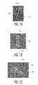
- FIG. 1Ashows a three dimensional view of a vessel 104 having different contrasts along the vessel 104 .
- the top portion 108 of the vessel 104is brighter than the bottom portion 112 of the vessel 104 because of the contrast agent taken by the patient.
- This change in contrastresults in edges generated when an orthogonal (i.e., cross-sectional) view of the vessel 104 is used. These edges can result in inaccuracy when an algorithm is used to determine the boundaries of the vessel 104 .
- FIG. 1Bshows an orthogonal view of three vessels 116 , 120 , 124 .
- FIG. 1Cshows an orthogonal view of two vessels 128 , 132 . Each vessel's boundary is difficult to distinguish from the other's boundary because of the significant diffusion 134 of the boundaries.
- Another exampleis a “snake” model for segmenting vessel boundaries in the planes orthogonal to the vessel centerline.
- the “snake” modeltraditionally “inserts” a tube having a smaller diameter than the vessel into a representation of the vessel and then uses parameters to cause the tube to expand until reaching the vessel's walls.
- the selection of the parametersare often initially estimated. An inaccurate selection of one or more parameters may result in the tube expanding beyond the actual vessel boundary.
- the snake modeldoes not always provide accurate results.
- Image discontinuitiesare detected via mean-shift analysis along the rays.
- Mean-shift analysiswhich operates in the joint spatial-range domain where the space of the 2 dimensional lattice represents the spatial domain and the space of intensity values constitutes the range domain, is often used for robustly detecting object boundaries in images. This approach is often effective when vessel boundaries are well isolated. It is often difficult, however, to estimate parameters such as spatial, range kernel filter sizes, and/or the amount of smoothness constraints for the robust segmentation of vessels. In particular, the use of a single spatial scale and curvature based smoothness constraints are typically not enough for accurate results when vessels are not isolated very well.
- the present inventionis a method and system for detecting a boundary of a vessel in an image.
- An accurate detection of a boundaryrequires an accurate detection of edges related to the vessel boundary while not recognizing edges associated with other structures unrelated to the vessel boundary.
- Edgesare detected based on the change in intensity between data points over a plurality of distances.
- edgesare detected by propagating one or more rays along the vessel. A set of edges is then selected from the detected edges. Further, incorrect edges can be eliminated from the edges. Each edge in the selected set of edges can be selected based on its strength.
- An initial vessel boundaryis then determined based on the selected set of edges.
- the vesselmay be defined as a non-nested structure in order to determine the initial vessel boundary.
- a shape descriptore.g., one or more elliptical shape descriptors
- FIG. 1( a )shows a prior art three dimensional view of a vessel having different contrasts along the vessel
- FIG. 1( b )shows a prior art orthogonal view of three vessels
- FIG. 1( c )shows a prior art orthogonal view of two vessels having diffused boundaries
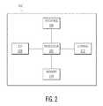
- FIG. 2is a high level block diagram of a computer in accordance with an embodiment of the invention.
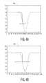
- FIG. 3shows graphical images of an intensity profile
- FIG. 4shows a graphical representation of edge detection on a gap edge
- FIG. 5shows a flowchart of the steps performed by the computer to detect vessel boundaries in accordance with an embodiment of the invention
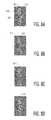
- FIG. 6shows images illustrating the steps used to detect vessel boundaries in accordance with an embodiment of the invention
- FIG. 7( a )shows a diagram of local grouping of edges in accordance with an embodiment of the invention
- FIG. 7( b )shows a cubic spline being used to bridge gaps in a vessel boundary in accordance with an embodiment of the invention
- FIG. 7( c )shows a closed curve constructed from elliptical Fourier descriptors of a set of curve segments in accordance with an embodiment of the invention.
- FIGS. 8( a )-( h )show images illustrating the steps used to detect vessel boundaries of a vessel in an initial image in accordance with an embodiment of the invention.
- Computer 202contains a processor 204 which controls the overall operation of computer 202 by executing computer program instructions which define such operation.
- the computer program instructionsmay be stored in a storage device 212 (e.g., magnetic disk) and loaded into memory 210 when execution of the computer program instructions is desired.
- Computer 202also includes one or more interfaces 206 for communicating with other devices (e.g., locally or via a network).
- Computer 202also includes input/output 208 which represents devices which allow for user interaction with the computer 202 (e.g., display, keyboard, mouse, speakers, buttons, etc.).
- input/output 208represents devices which allow for user interaction with the computer 202 (e.g., display, keyboard, mouse, speakers, buttons, etc.).
- FIG. 2is a high level representation of some of the components of such a computer for illustrative purposes.
- the processing steps described hereinmay also be implemented using dedicated hardware, the circuitry of which is configured specifically for implementing such processing steps. Alternatively, the processing steps may be implemented using various combinations of hardware and software. Also, the processing steps may take place in a computer or may be part of a larger machine (e.g., a medical imaging machine).
- computer 202uses displacement vectors of mean-shift analysis for detecting edges in multiple scales (i.e., over a plurality of distances).
- a 1-dimensional intensity profile(ray) is obtained from a gray level image. Each pixel along the ray is characterized by a location x and an intensity value I.
- an input ray of N pixelsis represented as a collection of 2-dimensional points ⁇ x i , I i ⁇ .
- the 2-dimensional space constructed as beforeis called the joint spatial-intensity domain.
- mean shift filteringis applied to this joint domain.
- the output of the mean-shift filterincludes a displacement vector ⁇ d i ⁇ which measures the spatial movement of each spatial point.
- each point in this spatial-range domainis processed via the mean shift operator until convergence.
- the robustness and accuracy of segmentation resultsoften heavily depend on the selection of spatial ( ⁇ x ) and range ( ⁇ i ) scale parameters of mean-shift analysis because vessel boundaries are often in many spatial and range scales.
- the computer 202executes a geometry-based algorithm that operates solely on the edges of intensity data for detecting vessel edges in multiple scales.
- FIG. 3shows a graphical representation of mean-shift filtering of a typical vessel edge. Diffuse edges, low contrast edges, and gap edges occur frequently, even in a single cross-sectional vessel boundary (e.g., as shown in FIG. 1 ( c )).
- the computer 202performs a boundary extraction method which combines the edges obtained from different spatial scales of mean-shift filtering along a ray.
- FIG. 3shows a transition 304 of an edge from a high intensity area 308 (e.g., a bright area) to a low intensity area 312 (e.g., a dark area) in an intensity profile 316 .
- the x-axis of FIG. 3represents distance along an image (i.e., scale) and the y-axis of FIG. 3 represents intensities for the left and right plots and represents displacement values in the middle plot.
- the longer (i.e., the greater amount of distance of) the transition 304the more image processing typically needed in order to detect the edge. In other words, the larger the scale (i.e., distance), the more image processing is needed in order to determine that the transition is an edge.
- edgesThere are typically two main difficulties with obtaining the correct edge from multi-scale edges. First, multiple erroneous edges are often present in the vicinity of the correct edge due to presence of noise in the intensity data. These edges do not typically correspond to semantically correct structures, e.g., a vessel boundary. As a result, these edges should be deleted. Second, there are often several edges along a ray corresponding to the structures of the boundaries. The edge corresponding to the boundary of a vessel can be determined from the geometric properties of the vessels and perceptual edge organization. In one embodiment, incorrect edges present along a ray can be removed based on edge confidence and edge strength.
- Image 320shows displacement vectors.
- the divergence of displacement vectorscorresponds to the local mode of intensity, i.e., the clustering of intensity data.
- the intensity datacan be locally clustered around the edge by mean-shift, if the proper scale, ( ⁇ x ), is chosen.
- the local clusteringis used to define the edge confidence.
- the edge confidencemeasures the validity of an edge by checking the presence of local clustering. Specifically, the edge confidence for scale ( ⁇ xk ) at location/is given by:
- edges with small confidenceare deleted. Edges having small confidence can form from applying small-scale mean-shift filtering on diffused edges.
- high confidence edgesalso form in the vicinity of a correct edge.
- the edge strengthis the intensity difference between the intensity at the edge location and the convergence location.
- Convergence locationscorrespond to the spatial locations where the displacement vectors terminate after mean-shift filtering.
- Image 324illustrates filtered intensity and original intensity together.
- the points representing the original intensityare line 328 (also shown in the left plot).
- FIG. 4shows a graphical representation 400 of mean-shift based edge detection on a gap edge (i.e., where the presence of nearby structures alters the intensity profile significantly).
- the detail analysis of mean-shift filteringpoints out that the edge location and the edge strength can be accurately computed from one side of the filter.
- the edge strengthis measured from the one side.
- the correct sideis determined from the edge confidences of the sides. In particular and in one embodiment, the side that gives higher edge confidence is selected for the edge strength.
- An edgeis then eliminated based on its strength and local mode. An edge is a correct edge if it is not located under the local mode of another edge. If it falls inside the local mode of another edge, it must have higher edge strength.
- the local mode of an edgecorresponds to the interval between its convergence points.
- the correct edge locationis obtained (shown in image 404 ). Larger scale mean-shift moves the edge to the left and lowers the edge strength E s .
- FIG. 5shows a flowchart illustrating the algorithm for selecting edges corresponding to the cross-sectional boundary of vessels.
- a prominent edge selection algorithm 504an edge grouping algorithm 508 , and then an algorithm to determine the vessel boundary from elliptical shape descriptors 512 are implemented.
- the prominent edge selection algorithm 504assumes that vessels are not embedded inside other bright structures. The vessels are therefore locally surrounded by darker background. This assumption is referred to below as a “no nested structures” assumption. This assumption may not be valid if vessels are fully surrounded by darker appearing plaques.
- the prominent edges from multi-scale edgesare determined by the “no nested structures assumption”. Geometrically, the first significant edge (strength) encountered during a propagation along the rays from the seed point out often corresponds to the vessel boundary if there is no significant noise inside the vessels. Therefore, an edge is deleted from an edge map if there is a much more significant edge present on the right side (outward).
- the edge E iis deleted if E si k 1 E sj where j i ⁇ 0 or if k 1 E si ⁇ E sj where i j ⁇ 0.
- k 1is a parameter which specifies relative strength of edges.
- the computerapplies a range of k 1 values to select the prominent edges from multi-scales. For example, k 1 can be set to 0.1, 0.2, 0.3, 0.5, 0.7, and 0.9 and all of the prominent edges are marked in a single image.
- FIG. 6shows multiple images including a vessel with marked edges.
- image 604includes vessel 608 that has edges such as edge 612 .
- the image 604also includes other edges not related to vessel 608 , such as edge 616 .
- image 620has edges such as edge 624 of vessel 628 and edge 632 unrelated to vessel 628 .
- the prominent edgesare selected while the other edges, such as edges 616 and 632 , are removed. This prominent edge selection is shown in images 636 and 640 . Most of the edges unrelated to the respective vessel 608 , 628 have been removed.
- the edge grouping algorithm 508is then executed.
- the edge grouping algorithm 508organizes edges into “long smooth curves,” such as curves 644 , 648 .
- FIG. 7( a )shows a diagram of local grouping of edges 704 , 708 .
- the edge grouping algorithm 508exploits the angle Q i 712 , and distance (length) L i 716 between edge elements (i.e., edges 704 , 708 ). Specifically, edge grouping starts from three edge elements, which forms a smooth curve segment, i.e., small angle Q i 712 . The curve then expands in two directions by adding more edge elements based on the neighboring angles. When multiple edge elements are “good” candidates for smoothness during the expansion of a curve segment, a branch point forms and new curve segments are initialized from this branch point. This iterative edge grouping terminates when all edge elements are considered for local grouping.
- one or more shape descriptorsis applied.
- elliptical shape descriptorsare applied.
- the goal of this algorithmis to select a subset of k curve segments which correspond to the cross-sectional boundary of vessels. This can be accomplished by considering all geometrically possible subsets of curve segments and selecting a subset that is most similar to an ellipse.
- Geometrically possible curve segmentscorrespond to the segments, which form smoother and longer curve segments when they are joined together without breaking them into pieces. Disjoint curve segments may form smooth curves, which then results in gaps between them. Gaps can occur when some parts of vessel boundary do not contain any edge due to the presence of nearby bright structures.
- FIG. 7( b )shows a vessel boundary 720 having gaps.
- arteries touch veinsin contrast enhanced MRA, there is no boundary between them.
- nearby vesselsoften remove some of the edges from vessel boundaries, thereby resulting in gaps.
- CTAthere may be no boundary between bone and a touching vessel due to intensity similarities.
- gapscan also form in the edge grouping stage due to the noise in the vessel boundaries.
- FIG. 7( b )shows a cubic spline 724 being used to bridge the gaps in the vessel boundary 720 .
- the curve segments that best (i.e., most accurately) represent the cross-sectional boundary of a vesselis determined by an elliptical fit measure.
- an elliptical fit measureIn particular, while the global shape of a vessel boundary resembles an ellipse, the vessel boundary also may exhibit local variations from an ellipse due to the presence of nearby vessels. These local deformations should be preserved for an accurate boundary representation.
- elliptical Fourier descriptorsare used to obtain the best curve from all of the possible ellipses.
- Fourier descriptorsrefer to the utilization of Fourier analysis, primarily the Fourier series, as a curve fitting technique that can numerically describe the shape of irregular structures.
- an elliptical fit measureis computed for each geometrically possible subset of curve segments by elliptical Fourier descriptors. Among them, a subset of curve segments that best fits to an ellipse is selected as the boundary of vessels.
- FIG. 7( c )shows a closed curve 730 constructed from the elliptical Fourier descriptors of a set of curve segments.
- several Fourier coefficientswere used because a low number of coefficients (e.g., less than 5) does not capture local deformations of boundary while a high number of coefficients (e.g., greater than 10) allows too much local deformation.
- FIGS. 8( a )-( h )show the algorithms for detecting vessel boundaries being used on an initial image 804 . All parameters associated with the algorithm remain constant throughout the algorithm processing.
- the initial image 804is an orthogonal view of a vessel 802 .
- the initial image 804includes edges (e.g., edges 808 and 812 ).
- the computer 202selects a seed point and then propagates rays from that seed point. Multi-scale edges are detected along the rays (e.g., 1 dimensional rays).
- Image 816illustrates the next step in the algorithm—to eliminate incorrect edges (shown in white), such as incorrect edge 820 . After the incorrect edges 820 are eliminated, image 824 is formed.
- Prominent edgesare then selected in image 828 by setting k 1 to 0.1, 0.2, 0.3, 0.5, 0.7, and 0.9.
- Curve segmentssuch as curve segment 832 , are then obtained in image 836 from the local edge grouping algorithm. These curve segments contain gaps, such as gap 840 . The gaps are filled in using cubic spline (shown in white in image 844 ) between curve segments.
- the computer 202then represents the curve set using Elliptical Fourier representation 846 (shown in white in image 848 ).
- the vessel boundary 852is then obtained in image 856 from the elliptical fit.
- the algorithmcan also be used to construct a 3 dimensional vessel.
- the direction of the vesselis first determined.
- the direction of the vesselis determined based on the eigenvalue analysis of Hessian matrix.
- the algorithmis applied at a single seed point to determine a vessel boundary at that location.
- the seed pointis then incrementally moved along the direction of the vessel and the algorithm is applied at each seed point, resulting in the obtaining of many vessel boundaries along the direction of the vessel. These boundaries can then be combined together to create a 3 dimensional representation of the vessel.
- This techniquecan enable accurate modeling of stenosis and aneurysms.
Landscapes
- Engineering & Computer Science (AREA)
- Physics & Mathematics (AREA)
- Computer Vision & Pattern Recognition (AREA)
- General Physics & Mathematics (AREA)
- Theoretical Computer Science (AREA)
- Geometry (AREA)
- Apparatus For Radiation Diagnosis (AREA)
- Image Processing (AREA)
- Magnetic Resonance Imaging Apparatus (AREA)
- Measuring And Recording Apparatus For Diagnosis (AREA)
- Image Analysis (AREA)
Abstract
Description


Claims (24)
Priority Applications (2)
| Application Number | Priority Date | Filing Date | Title |
|---|---|---|---|
| US11/399,164US7773787B2 (en) | 2005-04-19 | 2006-04-06 | Method and apparatus for detecting blood vessel boundaries using multi-scale mean-shift ray propagation |
| JP2006115697AJP2006297104A (en) | 2005-04-19 | 2006-04-19 | Method and system for detecting vessel boundary |
Applications Claiming Priority (2)
| Application Number | Priority Date | Filing Date | Title |
|---|---|---|---|
| US67263405P | 2005-04-19 | 2005-04-19 | |
| US11/399,164US7773787B2 (en) | 2005-04-19 | 2006-04-06 | Method and apparatus for detecting blood vessel boundaries using multi-scale mean-shift ray propagation |
Publications (2)
| Publication Number | Publication Date |
|---|---|
| US20060262988A1 US20060262988A1 (en) | 2006-11-23 |
| US7773787B2true US7773787B2 (en) | 2010-08-10 |
Family
ID=37111639
Family Applications (1)
| Application Number | Title | Priority Date | Filing Date |
|---|---|---|---|
| US11/399,164Active2028-11-29US7773787B2 (en) | 2005-04-19 | 2006-04-06 | Method and apparatus for detecting blood vessel boundaries using multi-scale mean-shift ray propagation |
Country Status (4)
| Country | Link |
|---|---|
| US (1) | US7773787B2 (en) |
| JP (1) | JP2006297104A (en) |
| CN (1) | CN1853569A (en) |
| DE (1) | DE102006017113A1 (en) |
Cited By (21)
| Publication number | Priority date | Publication date | Assignee | Title |
|---|---|---|---|---|
| US20130121555A1 (en)* | 2011-11-16 | 2013-05-16 | Herbert Bruder | Reconstruction of image data |
| US8463007B2 (en) | 2007-03-08 | 2013-06-11 | Sync-Rx, Ltd. | Automatic generation of a vascular skeleton |
| US8553933B2 (en) | 2010-11-10 | 2013-10-08 | Raytheon Company | Edge diversity object detection |
| US8582884B2 (en) | 2010-11-12 | 2013-11-12 | Raytheon Company | Approximation of an imaged object from edges detected from the underlying image |
| US8700130B2 (en) | 2007-03-08 | 2014-04-15 | Sync-Rx, Ltd. | Stepwise advancement of a medical tool |
| US8855744B2 (en) | 2008-11-18 | 2014-10-07 | Sync-Rx, Ltd. | Displaying a device within an endoluminal image stack |
| US9095313B2 (en) | 2008-11-18 | 2015-08-04 | Sync-Rx, Ltd. | Accounting for non-uniform longitudinal motion during movement of an endoluminal imaging probe |
| US9101286B2 (en) | 2008-11-18 | 2015-08-11 | Sync-Rx, Ltd. | Apparatus and methods for determining a dimension of a portion of a stack of endoluminal data points |
| US9144394B2 (en) | 2008-11-18 | 2015-09-29 | Sync-Rx, Ltd. | Apparatus and methods for determining a plurality of local calibration factors for an image |
| US9305334B2 (en) | 2007-03-08 | 2016-04-05 | Sync-Rx, Ltd. | Luminal background cleaning |
| US9375164B2 (en) | 2007-03-08 | 2016-06-28 | Sync-Rx, Ltd. | Co-use of endoluminal data and extraluminal imaging |
| US9629571B2 (en) | 2007-03-08 | 2017-04-25 | Sync-Rx, Ltd. | Co-use of endoluminal data and extraluminal imaging |
| US9855384B2 (en) | 2007-03-08 | 2018-01-02 | Sync-Rx, Ltd. | Automatic enhancement of an image stream of a moving organ and displaying as a movie |
| US9888969B2 (en) | 2007-03-08 | 2018-02-13 | Sync-Rx Ltd. | Automatic quantitative vessel analysis |
| US9974509B2 (en) | 2008-11-18 | 2018-05-22 | Sync-Rx Ltd. | Image super enhancement |
| US10362962B2 (en) | 2008-11-18 | 2019-07-30 | Synx-Rx, Ltd. | Accounting for skipped imaging locations during movement of an endoluminal imaging probe |
| US10716528B2 (en) | 2007-03-08 | 2020-07-21 | Sync-Rx, Ltd. | Automatic display of previously-acquired endoluminal images |
| US10748289B2 (en) | 2012-06-26 | 2020-08-18 | Sync-Rx, Ltd | Coregistration of endoluminal data points with values of a luminal-flow-related index |
| US11064964B2 (en) | 2007-03-08 | 2021-07-20 | Sync-Rx, Ltd | Determining a characteristic of a lumen by measuring velocity of a contrast agent |
| US11064903B2 (en) | 2008-11-18 | 2021-07-20 | Sync-Rx, Ltd | Apparatus and methods for mapping a sequence of images to a roadmap image |
| US11197651B2 (en) | 2007-03-08 | 2021-12-14 | Sync-Rx, Ltd. | Identification and presentation of device-to-vessel relative motion |
Families Citing this family (14)
| Publication number | Priority date | Publication date | Assignee | Title |
|---|---|---|---|---|
| US7343032B2 (en)* | 2005-09-01 | 2008-03-11 | Fujifilm Corporation | Method and apparatus for automatic and dynamic vessel detection |
| WO2007035688A2 (en)* | 2005-09-16 | 2007-03-29 | The Ohio State University | Method and apparatus for detecting intraventricular dyssynchrony |
| US8131043B2 (en)* | 2005-09-16 | 2012-03-06 | The Ohio State University | Method and apparatus for detecting interventricular dyssynchrony |
| US7953266B2 (en) | 2007-02-06 | 2011-05-31 | Siemens Medical Solutions Usa, Inc. | Robust vessel tree modeling |
| DE102008036812B4 (en)* | 2008-08-07 | 2010-07-15 | Siemens Aktiengesellschaft | Method and device for segmenting an object from an image data set |
| DE102009006636B4 (en)* | 2008-12-30 | 2016-02-18 | Siemens Aktiengesellschaft | Method for determining a 2D contour of a vessel structure depicted in 3D image data |
| US8768016B2 (en) | 2009-06-19 | 2014-07-01 | Carestream Health, Inc. | Method for quantifying caries |
| US9235901B2 (en)* | 2009-10-14 | 2016-01-12 | Carestream Health, Inc. | Method for locating an interproximal tooth region |
| US20130009989A1 (en)* | 2011-07-07 | 2013-01-10 | Li-Hui Chen | Methods and systems for image segmentation and related applications |
| JP5310803B2 (en)* | 2011-07-25 | 2013-10-09 | カシオ計算機株式会社 | Image processing apparatus, image processing method, and program |
| DE102014115851A1 (en)* | 2014-10-30 | 2016-05-04 | Physikalisch - Technische Bundesanstalt | Method and device for calculating, displaying and further processing local quality measures from a volume image data set |
| US11024034B2 (en)* | 2019-07-02 | 2021-06-01 | Acist Medical Systems, Inc. | Image segmentation confidence determination |
| CN113781482B (en)* | 2021-11-11 | 2022-02-15 | 山东精良海纬机械有限公司 | Method and system for detecting crack defects of mechanical parts in complex environment |
| CN118806225B (en)* | 2024-09-18 | 2024-11-22 | 长春中科长光时空光电技术有限公司 | Laser treatment equipment control method and treatment system based on optical imaging guidance |
Citations (8)
| Publication number | Priority date | Publication date | Assignee | Title |
|---|---|---|---|---|
| US6047090A (en)* | 1996-07-31 | 2000-04-04 | U.S. Philips Corporation | Method and device for automatic segmentation of a digital image using a plurality of morphological opening operation |
| US6385332B1 (en)* | 1999-02-19 | 2002-05-07 | The John P. Roberts Research Institute | Automated segmentation method for 3-dimensional ultrasound |
| US20030095121A1 (en) | 2001-10-23 | 2003-05-22 | Tek Huseyin | Vessel detection by mean shift based ray propagation |
| US6590999B1 (en)* | 2000-02-14 | 2003-07-08 | Siemens Corporate Research, Inc. | Real-time tracking of non-rigid objects using mean shift |
| US6658143B2 (en)* | 2002-04-29 | 2003-12-02 | Amersham Biosciences Corp. | Ray-based image analysis for biological specimens |
| US6785409B1 (en)* | 2000-10-24 | 2004-08-31 | Koninklijke Philips Electronics, N.V. | Segmentation method and apparatus for medical images using diffusion propagation, pixel classification, and mathematical morphology |
| US20040171932A1 (en)* | 2002-11-27 | 2004-09-02 | Raghav Raman | Quantification of aortoiliac endoluminal irregularity |
| US7015907B2 (en) | 2002-04-18 | 2006-03-21 | Siemens Corporate Research, Inc. | Segmentation of 3D medical structures using robust ray propagation |
- 2006
- 2006-04-06USUS11/399,164patent/US7773787B2/enactiveActive
- 2006-04-10DEDE102006017113Apatent/DE102006017113A1/ennot_activeCeased
- 2006-04-19CNCNA2006100840175Apatent/CN1853569A/enactivePending
- 2006-04-19JPJP2006115697Apatent/JP2006297104A/enactivePending
Patent Citations (10)
| Publication number | Priority date | Publication date | Assignee | Title |
|---|---|---|---|---|
| US6047090A (en)* | 1996-07-31 | 2000-04-04 | U.S. Philips Corporation | Method and device for automatic segmentation of a digital image using a plurality of morphological opening operation |
| US6385332B1 (en)* | 1999-02-19 | 2002-05-07 | The John P. Roberts Research Institute | Automated segmentation method for 3-dimensional ultrasound |
| US6590999B1 (en)* | 2000-02-14 | 2003-07-08 | Siemens Corporate Research, Inc. | Real-time tracking of non-rigid objects using mean shift |
| US6785409B1 (en)* | 2000-10-24 | 2004-08-31 | Koninklijke Philips Electronics, N.V. | Segmentation method and apparatus for medical images using diffusion propagation, pixel classification, and mathematical morphology |
| US20030095121A1 (en) | 2001-10-23 | 2003-05-22 | Tek Huseyin | Vessel detection by mean shift based ray propagation |
| DE10249320A1 (en) | 2001-10-23 | 2003-05-28 | Siemens Corp Res Inc | Two-dimensional medical structure segmentation method, involves selecting structure of image data and initializing rays to form curve based on speed function to segment structure when all rays join on their boundary |
| US6947040B2 (en) | 2001-10-23 | 2005-09-20 | Siemens Corporate Research, Inc. | Vessel detection by mean shift based ray propagation |
| US7015907B2 (en) | 2002-04-18 | 2006-03-21 | Siemens Corporate Research, Inc. | Segmentation of 3D medical structures using robust ray propagation |
| US6658143B2 (en)* | 2002-04-29 | 2003-12-02 | Amersham Biosciences Corp. | Ray-based image analysis for biological specimens |
| US20040171932A1 (en)* | 2002-11-27 | 2004-09-02 | Raghav Raman | Quantification of aortoiliac endoluminal irregularity |
Non-Patent Citations (6)
| Title |
|---|
| Elder et al., "Contour Grouping With Prior Models", IEEE Transactions on Pattern Analysis and Machine Intelligence, vol. 25, Issue 6, Jun. 2003, pp. 661-674. |
| Rosenfeld et al. (May 1971) "Edge and curve detection for visual scene analysis." IEEE Trans. on Computers, vol. C-20 Issue 5, pp. 562-569.* |
| Setarehdan et al. (Nov. 1999) "Automatic cardiac LV boundary detection and tracking Using hybrid fuzzy temporal and fuzzy multiscale edge detection." IEEE Trans. on Biomedical Engineering, vol. 46 No. 11, pp. 1364-1378.* |
| Tek et al. (Dec. 2001) "Vessel detection by mean shift based ray propagation." Proc. IEEE Workshop on Mathematical Methods in Biomedical Image Analysis, pp. 228-235.* |
| Tek et al. (Oct. 2005) "Multi-scale vessel boundary detection." Proc. 1st Int'l Workshop on Computer Vision for Biomedical Image Applications, pp. 388-398.* |
| Xu et al. (Oct. 2001) "Atherosclerotic plaque segmentation at human carotid artery based on multiple contrast weighting MR images." Proc. 2001 Int'l Conf. on Image Processing, vol. 2 pp. 849-852.* |
Cited By (40)
| Publication number | Priority date | Publication date | Assignee | Title |
|---|---|---|---|---|
| US9375164B2 (en) | 2007-03-08 | 2016-06-28 | Sync-Rx, Ltd. | Co-use of endoluminal data and extraluminal imaging |
| US10307061B2 (en) | 2007-03-08 | 2019-06-04 | Sync-Rx, Ltd. | Automatic tracking of a tool upon a vascular roadmap |
| US8542900B2 (en) | 2007-03-08 | 2013-09-24 | Sync-Rx Ltd. | Automatic reduction of interfering elements from an image stream of a moving organ |
| US12053317B2 (en) | 2007-03-08 | 2024-08-06 | Sync-Rx Ltd. | Determining a characteristic of a lumen by measuring velocity of a contrast agent |
| US11197651B2 (en) | 2007-03-08 | 2021-12-14 | Sync-Rx, Ltd. | Identification and presentation of device-to-vessel relative motion |
| US8670603B2 (en) | 2007-03-08 | 2014-03-11 | Sync-Rx, Ltd. | Apparatus and methods for masking a portion of a moving image stream |
| US8693756B2 (en) | 2007-03-08 | 2014-04-08 | Sync-Rx, Ltd. | Automatic reduction of interfering elements from an image stream of a moving organ |
| US8700130B2 (en) | 2007-03-08 | 2014-04-15 | Sync-Rx, Ltd. | Stepwise advancement of a medical tool |
| US8781193B2 (en) | 2007-03-08 | 2014-07-15 | Sync-Rx, Ltd. | Automatic quantitative vessel analysis |
| US11179038B2 (en) | 2007-03-08 | 2021-11-23 | Sync-Rx, Ltd | Automatic stabilization of a frames of image stream of a moving organ having intracardiac or intravascular tool in the organ that is displayed in movie format |
| US9008367B2 (en) | 2007-03-08 | 2015-04-14 | Sync-Rx, Ltd. | Apparatus and methods for reducing visibility of a periphery of an image stream |
| US9008754B2 (en) | 2007-03-08 | 2015-04-14 | Sync-Rx, Ltd. | Automatic correction and utilization of a vascular roadmap comprising a tool |
| US9014453B2 (en) | 2007-03-08 | 2015-04-21 | Sync-Rx, Ltd. | Automatic angiogram detection |
| US11064964B2 (en) | 2007-03-08 | 2021-07-20 | Sync-Rx, Ltd | Determining a characteristic of a lumen by measuring velocity of a contrast agent |
| US9308052B2 (en) | 2007-03-08 | 2016-04-12 | Sync-Rx, Ltd. | Pre-deployment positioning of an implantable device within a moving organ |
| US10716528B2 (en) | 2007-03-08 | 2020-07-21 | Sync-Rx, Ltd. | Automatic display of previously-acquired endoluminal images |
| US10499814B2 (en) | 2007-03-08 | 2019-12-10 | Sync-Rx, Ltd. | Automatic generation and utilization of a vascular roadmap |
| US9216065B2 (en) | 2007-03-08 | 2015-12-22 | Sync-Rx, Ltd. | Forming and displaying a composite image |
| US8463007B2 (en) | 2007-03-08 | 2013-06-11 | Sync-Rx, Ltd. | Automatic generation of a vascular skeleton |
| US9305334B2 (en) | 2007-03-08 | 2016-04-05 | Sync-Rx, Ltd. | Luminal background cleaning |
| US9968256B2 (en) | 2007-03-08 | 2018-05-15 | Sync-Rx Ltd. | Automatic identification of a tool |
| US9629571B2 (en) | 2007-03-08 | 2017-04-25 | Sync-Rx, Ltd. | Co-use of endoluminal data and extraluminal imaging |
| US9717415B2 (en) | 2007-03-08 | 2017-08-01 | Sync-Rx, Ltd. | Automatic quantitative vessel analysis at the location of an automatically-detected tool |
| US9855384B2 (en) | 2007-03-08 | 2018-01-02 | Sync-Rx, Ltd. | Automatic enhancement of an image stream of a moving organ and displaying as a movie |
| US9888969B2 (en) | 2007-03-08 | 2018-02-13 | Sync-Rx Ltd. | Automatic quantitative vessel analysis |
| US10226178B2 (en) | 2007-03-08 | 2019-03-12 | Sync-Rx Ltd. | Automatic reduction of visibility of portions of an image |
| US11064903B2 (en) | 2008-11-18 | 2021-07-20 | Sync-Rx, Ltd | Apparatus and methods for mapping a sequence of images to a roadmap image |
| US11883149B2 (en) | 2008-11-18 | 2024-01-30 | Sync-Rx Ltd. | Apparatus and methods for mapping a sequence of images to a roadmap image |
| US9101286B2 (en) | 2008-11-18 | 2015-08-11 | Sync-Rx, Ltd. | Apparatus and methods for determining a dimension of a portion of a stack of endoluminal data points |
| US10362962B2 (en) | 2008-11-18 | 2019-07-30 | Synx-Rx, Ltd. | Accounting for skipped imaging locations during movement of an endoluminal imaging probe |
| US9144394B2 (en) | 2008-11-18 | 2015-09-29 | Sync-Rx, Ltd. | Apparatus and methods for determining a plurality of local calibration factors for an image |
| US9974509B2 (en) | 2008-11-18 | 2018-05-22 | Sync-Rx Ltd. | Image super enhancement |
| US9095313B2 (en) | 2008-11-18 | 2015-08-04 | Sync-Rx, Ltd. | Accounting for non-uniform longitudinal motion during movement of an endoluminal imaging probe |
| US8855744B2 (en) | 2008-11-18 | 2014-10-07 | Sync-Rx, Ltd. | Displaying a device within an endoluminal image stack |
| US8553933B2 (en) | 2010-11-10 | 2013-10-08 | Raytheon Company | Edge diversity object detection |
| US8582884B2 (en) | 2010-11-12 | 2013-11-12 | Raytheon Company | Approximation of an imaged object from edges detected from the underlying image |
| US20130121555A1 (en)* | 2011-11-16 | 2013-05-16 | Herbert Bruder | Reconstruction of image data |
| US9147267B2 (en)* | 2011-11-16 | 2015-09-29 | Siemens Aktiengesellschaft | Reconstruction of image data |
| US10748289B2 (en) | 2012-06-26 | 2020-08-18 | Sync-Rx, Ltd | Coregistration of endoluminal data points with values of a luminal-flow-related index |
| US10984531B2 (en) | 2012-06-26 | 2021-04-20 | Sync-Rx, Ltd. | Determining a luminal-flow-related index using blood velocity determination |
Also Published As
| Publication number | Publication date |
|---|---|
| DE102006017113A1 (en) | 2006-11-09 |
| JP2006297104A (en) | 2006-11-02 |
| CN1853569A (en) | 2006-11-01 |
| US20060262988A1 (en) | 2006-11-23 |
Similar Documents
| Publication | Publication Date | Title |
|---|---|---|
| US7773787B2 (en) | Method and apparatus for detecting blood vessel boundaries using multi-scale mean-shift ray propagation | |
| US6947040B2 (en) | Vessel detection by mean shift based ray propagation | |
| US7711167B2 (en) | Fissure detection methods for lung lobe segmentation | |
| US20070217668A1 (en) | Method and apparatus of segmenting an object in a data set and of determination of the volume of segmented object | |
| US10210612B2 (en) | Method and system for machine learning based estimation of anisotropic vessel orientation tensor | |
| US20070249912A1 (en) | Method for artery-vein image separation in blood pool contrast agents | |
| US8170642B2 (en) | Method and system for lymph node detection using multiple MR sequences | |
| US8577104B2 (en) | Liver lesion segmentation | |
| WO2012040410A2 (en) | Method and system for liver lesion detection | |
| JP7539981B2 (en) | Automatic classification of liver disease severity from non-invasive radiological imaging | |
| De Koning et al. | Automated segmentation and analysis of vascular structures in magnetic resonance angiographic images | |
| US12089987B2 (en) | Computer based method for classifying a mass of an organ as a cyst | |
| Hameeteman et al. | Carotid wall volume quantification from magnetic resonance images using deformable model fitting and learning-based correction of systematic errors | |
| Forkert et al. | Automatic brain segmentation in time-of-flight MRA images | |
| Ralli et al. | Segmentation of the biliary tree from MRCP images via the monogenic signal | |
| Larrabide et al. | An image segmentation method based on a discrete version of the topological derivative | |
| Young et al. | Vessel segmentation for visualization of MRA with blood pool contrast agent | |
| Czajkowska et al. | Skeleton graph matching vs. maximum weight cliques aorta registration techniques | |
| KR101126223B1 (en) | Liver segmentation method using MR images | |
| Mitéran et al. | Automatic determination of aortic compliance based on MRI and adapted curvilinear detector | |
| Orkisz et al. | Models, algorithms and applications in vascular image segmentation | |
| Liu et al. | Segmentation refinement of small-size juxta-pleural lung nodules in CT scans | |
| EP4264542A1 (en) | Image analysis method for improved clinical decision making | |
| CN101278316B (en) | System and method for automatic segmentation of vessels in breast MR sequences | |
| Molinari et al. | Automated measurement of carotid artery intima-media thickness |
Legal Events
| Date | Code | Title | Description |
|---|---|---|---|
| AS | Assignment | Owner name:SIEMENS CORPORATE RESEARCH, INC., NEW JERSEY Free format text:ASSIGNMENT OF ASSIGNORS INTEREST;ASSIGNORS:TEK, HUSEYIN;COMANICIU, DORIN;AYVACI, ALPER;SIGNING DATES FROM 20060526 TO 20060629;REEL/FRAME:017933/0878 Owner name:SIEMENS CORPORATE RESEARCH, INC., NEW JERSEY Free format text:ASSIGNMENT OF ASSIGNORS INTEREST;ASSIGNORS:TEK, HUSEYIN;COMANICIU, DORIN;AYVACI, ALPER;REEL/FRAME:017933/0878;SIGNING DATES FROM 20060526 TO 20060629 | |
| AS | Assignment | Owner name:SIEMENS MEDICAL SOLUTIONS USA, INC.,PENNSYLVANIA Free format text:ASSIGNMENT OF ASSIGNORS INTEREST;ASSIGNOR:SIEMENS CORPORATE RESEARCH, INC.;REEL/FRAME:019309/0669 Effective date:20070430 Owner name:SIEMENS MEDICAL SOLUTIONS USA, INC., PENNSYLVANIA Free format text:ASSIGNMENT OF ASSIGNORS INTEREST;ASSIGNOR:SIEMENS CORPORATE RESEARCH, INC.;REEL/FRAME:019309/0669 Effective date:20070430 | |
| STCF | Information on status: patent grant | Free format text:PATENTED CASE | |
| FPAY | Fee payment | Year of fee payment:4 | |
| MAFP | Maintenance fee payment | Free format text:PAYMENT OF MAINTENANCE FEE, 8TH YEAR, LARGE ENTITY (ORIGINAL EVENT CODE: M1552) Year of fee payment:8 | |
| MAFP | Maintenance fee payment | Free format text:PAYMENT OF MAINTENANCE FEE, 12TH YEAR, LARGE ENTITY (ORIGINAL EVENT CODE: M1553); ENTITY STATUS OF PATENT OWNER: LARGE ENTITY Year of fee payment:12 |