US7773699B2 - Method and apparatus for channel quality measurements - Google Patents
Method and apparatus for channel quality measurementsDownload PDFInfo
- Publication number
- US7773699B2 US7773699B2US10/038,916US3891602AUS7773699B2US 7773699 B2US7773699 B2US 7773699B2US 3891602 AUS3891602 AUS 3891602AUS 7773699 B2US7773699 B2US 7773699B2
- Authority
- US
- United States
- Prior art keywords
- symbols
- ofdm
- signaling message
- encoded
- stbc
- Prior art date
- Legal status (The legal status is an assumption and is not a legal conclusion. Google has not performed a legal analysis and makes no representation as to the accuracy of the status listed.)
- Active, expires
Links
- 238000000034methodMethods0.000titleclaimsabstractdescription63
- 238000005259measurementMethods0.000titleabstractdescription29
- 230000011664signalingEffects0.000claimsabstractdescription92
- 230000005540biological transmissionEffects0.000claimsabstractdescription15
- 238000013507mappingMethods0.000claimsdescription37
- 239000000969carrierSubstances0.000claimsdescription30
- 102100026758Serine/threonine-protein kinase 16Human genes0.000claimsdescription23
- 101710184778Serine/threonine-protein kinase 16Proteins0.000claimsdescription23
- 238000012545processingMethods0.000claimsdescription6
- 238000004422calculation algorithmMethods0.000claimsdescription5
- 238000012937correctionMethods0.000claimsdescription5
- 238000004519manufacturing processMethods0.000claimsdescription3
- 230000003044adaptive effectEffects0.000abstractdescription10
- 108091006146ChannelsProteins0.000description161
- 239000011159matrix materialSubstances0.000description16
- 238000013461designMethods0.000description9
- 238000010586diagramMethods0.000description8
- 238000005562fadingMethods0.000description7
- 238000004891communicationMethods0.000description6
- 238000013459approachMethods0.000description5
- 238000004088simulationMethods0.000description5
- 230000008901benefitEffects0.000description4
- 230000001427coherent effectEffects0.000description4
- 238000004364calculation methodMethods0.000description3
- 238000003780insertionMethods0.000description3
- 230000037431insertionEffects0.000description3
- 230000010363phase shiftEffects0.000description3
- 230000006978adaptationEffects0.000description2
- 230000006735deficitEffects0.000description2
- 238000001514detection methodMethods0.000description2
- 238000005516engineering processMethods0.000description2
- 238000000605extractionMethods0.000description2
- 238000000691measurement methodMethods0.000description2
- 238000010606normalizationMethods0.000description2
- 230000003595spectral effectEffects0.000description2
- 238000007476Maximum LikelihoodMethods0.000description1
- 229910052799carbonInorganic materials0.000description1
- 230000015556catabolic processEffects0.000description1
- 238000007796conventional methodMethods0.000description1
- 238000006731degradation reactionMethods0.000description1
- 229910003460diamondInorganic materials0.000description1
- 239000010432diamondSubstances0.000description1
- 230000000694effectsEffects0.000description1
- 229940050561matrix productDrugs0.000description1
- 230000000737periodic effectEffects0.000description1
- 238000012552reviewMethods0.000description1
- 238000005070samplingMethods0.000description1
- 230000002123temporal effectEffects0.000description1
- XLYOFNOQVPJJNP-UHFFFAOYSA-NwaterSubstancesOXLYOFNOQVPJJNP-UHFFFAOYSA-N0.000description1
Images


Classifications
- H—ELECTRICITY
- H04—ELECTRIC COMMUNICATION TECHNIQUE
- H04L—TRANSMISSION OF DIGITAL INFORMATION, e.g. TELEGRAPHIC COMMUNICATION
- H04L1/00—Arrangements for detecting or preventing errors in the information received
- H04L1/02—Arrangements for detecting or preventing errors in the information received by diversity reception
- H04L1/06—Arrangements for detecting or preventing errors in the information received by diversity reception using space diversity
- H04L1/0618—Space-time coding
- H04L1/0631—Receiver arrangements
- H—ELECTRICITY
- H04—ELECTRIC COMMUNICATION TECHNIQUE
- H04B—TRANSMISSION
- H04B17/00—Monitoring; Testing
- H—ELECTRICITY
- H04—ELECTRIC COMMUNICATION TECHNIQUE
- H04L—TRANSMISSION OF DIGITAL INFORMATION, e.g. TELEGRAPHIC COMMUNICATION
- H04L1/00—Arrangements for detecting or preventing errors in the information received
- H04L1/0001—Systems modifying transmission characteristics according to link quality, e.g. power backoff
- H04L1/0002—Systems modifying transmission characteristics according to link quality, e.g. power backoff by adapting the transmission rate
- H04L1/0003—Systems modifying transmission characteristics according to link quality, e.g. power backoff by adapting the transmission rate by switching between different modulation schemes
- H—ELECTRICITY
- H04—ELECTRIC COMMUNICATION TECHNIQUE
- H04L—TRANSMISSION OF DIGITAL INFORMATION, e.g. TELEGRAPHIC COMMUNICATION
- H04L1/00—Arrangements for detecting or preventing errors in the information received
- H04L1/0001—Systems modifying transmission characteristics according to link quality, e.g. power backoff
- H04L1/0009—Systems modifying transmission characteristics according to link quality, e.g. power backoff by adapting the channel coding
- H—ELECTRICITY
- H04—ELECTRIC COMMUNICATION TECHNIQUE
- H04L—TRANSMISSION OF DIGITAL INFORMATION, e.g. TELEGRAPHIC COMMUNICATION
- H04L1/00—Arrangements for detecting or preventing errors in the information received
- H04L1/0001—Systems modifying transmission characteristics according to link quality, e.g. power backoff
- H04L1/0036—Systems modifying transmission characteristics according to link quality, e.g. power backoff arrangements specific to the receiver
- H—ELECTRICITY
- H04—ELECTRIC COMMUNICATION TECHNIQUE
- H04L—TRANSMISSION OF DIGITAL INFORMATION, e.g. TELEGRAPHIC COMMUNICATION
- H04L1/00—Arrangements for detecting or preventing errors in the information received
- H04L1/20—Arrangements for detecting or preventing errors in the information received using signal quality detector
- H04L1/208—Arrangements for detecting or preventing errors in the information received using signal quality detector involving signal re-encoding
- H—ELECTRICITY
- H04—ELECTRIC COMMUNICATION TECHNIQUE
- H04L—TRANSMISSION OF DIGITAL INFORMATION, e.g. TELEGRAPHIC COMMUNICATION
- H04L25/00—Baseband systems
- H04L25/02—Details ; arrangements for supplying electrical power along data transmission lines
- H04L25/0202—Channel estimation
- H04L25/0224—Channel estimation using sounding signals
- H04L25/0226—Channel estimation using sounding signals sounding signals per se
- H—ELECTRICITY
- H04—ELECTRIC COMMUNICATION TECHNIQUE
- H04L—TRANSMISSION OF DIGITAL INFORMATION, e.g. TELEGRAPHIC COMMUNICATION
- H04L25/00—Baseband systems
- H04L25/02—Details ; arrangements for supplying electrical power along data transmission lines
- H04L25/0202—Channel estimation
- H04L25/0224—Channel estimation using sounding signals
- H04L25/0228—Channel estimation using sounding signals with direct estimation from sounding signals
- H04L25/023—Channel estimation using sounding signals with direct estimation from sounding signals with extension to other symbols
- H04L25/0236—Channel estimation using sounding signals with direct estimation from sounding signals with extension to other symbols using estimation of the other symbols
- H—ELECTRICITY
- H04—ELECTRIC COMMUNICATION TECHNIQUE
- H04L—TRANSMISSION OF DIGITAL INFORMATION, e.g. TELEGRAPHIC COMMUNICATION
- H04L25/00—Baseband systems
- H04L25/02—Details ; arrangements for supplying electrical power along data transmission lines
- H04L25/03—Shaping networks in transmitter or receiver, e.g. adaptive shaping networks
- H04L25/03006—Arrangements for removing intersymbol interference
- H04L25/03178—Arrangements involving sequence estimation techniques
- H04L25/03312—Arrangements specific to the provision of output signals
- H04L25/03318—Provision of soft decisions
- H—ELECTRICITY
- H04—ELECTRIC COMMUNICATION TECHNIQUE
- H04L—TRANSMISSION OF DIGITAL INFORMATION, e.g. TELEGRAPHIC COMMUNICATION
- H04L25/00—Baseband systems
- H04L25/02—Details ; arrangements for supplying electrical power along data transmission lines
- H04L25/06—DC level restoring means; Bias distortion correction ; Decision circuits providing symbol by symbol detection
- H04L25/067—DC level restoring means; Bias distortion correction ; Decision circuits providing symbol by symbol detection providing soft decisions, i.e. decisions together with an estimate of reliability
- H—ELECTRICITY
- H04—ELECTRIC COMMUNICATION TECHNIQUE
- H04L—TRANSMISSION OF DIGITAL INFORMATION, e.g. TELEGRAPHIC COMMUNICATION
- H04L5/00—Arrangements affording multiple use of the transmission path
- H04L5/0001—Arrangements for dividing the transmission path
- H04L5/0014—Three-dimensional division
- H04L5/0023—Time-frequency-space
- H—ELECTRICITY
- H04—ELECTRIC COMMUNICATION TECHNIQUE
- H04L—TRANSMISSION OF DIGITAL INFORMATION, e.g. TELEGRAPHIC COMMUNICATION
- H04L5/00—Arrangements affording multiple use of the transmission path
- H04L5/003—Arrangements for allocating sub-channels of the transmission path
- H04L5/0048—Allocation of pilot signals, i.e. of signals known to the receiver
- H—ELECTRICITY
- H04—ELECTRIC COMMUNICATION TECHNIQUE
- H04W—WIRELESS COMMUNICATION NETWORKS
- H04W24/00—Supervisory, monitoring or testing arrangements
- H—ELECTRICITY
- H04—ELECTRIC COMMUNICATION TECHNIQUE
- H04L—TRANSMISSION OF DIGITAL INFORMATION, e.g. TELEGRAPHIC COMMUNICATION
- H04L5/00—Arrangements affording multiple use of the transmission path
- H04L5/003—Arrangements for allocating sub-channels of the transmission path
- H04L5/0053—Allocation of signalling, i.e. of overhead other than pilot signals
Definitions
- the inventionrelates to wireless data transmission, and more particularly to channel quality measurement in respect of such data transmission.
- Adaptive modulation and codingis a key enabling concept and technology for high-speed wireless data transmission.
- a wireless channelis typically a random fading channel.
- Adaptive coding and modulationis a commonly employed solution for transmitting data over such an unknown channel.
- Conventional design methodologyprovides a large fade margin in the transmit signal power to combat deep fades which may occur.
- Such fade marginsare typically at least 6 dB, which represents a 200-300% throughput loss.
- the aim of adaptive coding and modulationis to fully utilize the channel capacity and to minimize the need to use such a fade margin by dynamically selecting the best coding and modulation configuration on-the-fly. This requires the transmitter to have accurate information about the instantaneous channel quality.
- Such instantaneous channel quality informationis extracted at the receiver and fed back to the transmitter.
- the conventional approachis to measure the channel (signal) to interference power ratio (CIR) at the receiver front-end. Based on the instantaneous CIR and a targeted performance, the transmitter determines and applies the appropriate coding rate and modulation.
- CIRchannel to interference power ratio
- pilot based channel quality measurementscan be classified into two categories: (1) pilot based channel quality measurements and (2) decision feedback based channel quality measurements.
- These methodsuse the correlation of known sequences, typically Pseudo-Noise (PN) codes, with both the desired signal and the interference.
- PNPseudo-Noise
- FIG. 1shows a first, second and third base transceiver station (BTS) 100 , 110 , and 120 transmitting their respective signals, and a mobile station 130 receiving these signals.
- BTSbase transceiver station
- Mobile station 130is configured to receive, demodulate and decode a signal transmitted by the second base transceiver station 110 .
- the signals transmitted by the first base transceiver station 100 and the third base transceiver station 120are received as interference by the mobile station 130 .
- a channel associated with the signal having received signal power C transmitted by base transceiver station 2 (BTS 2 ) 110is the channel whose quality is to be measured.
- BTS 2base transceiver station 2
- the second BTS 110encodes a signal whose associated channel quality is to be measured, at ENCODER- 2 112 .
- the encoded signalis modulated using a PN Code which here is labelled Pilot-PN 2 114 before eventually being transmitted through an antenna 118 to the mobile station 130 .
- the first BTS 100encodes a signal, which appears as a first interference signal to the mobile station 130 , at ENCODER- 1 102 .
- This encoded signalis modulated using a PN Code Pilot-PN 1 104 before eventually being transmitted through an antenna 108 .
- the third BTS 120encodes a signal, which appears as a second interference signal to the mobile station 130 , at ENCODER- 3 122 .
- This encoded signalis modulated using a PN Code which here is labelled Pilot-PN 3 124 before eventually being transmitted through an antenna 128 .
- All three signals transmitted by antennas 108 , 118 , and 128are received by the mobile station 130 at the receiver front-end 134 through antenna 132 .
- the received signalis then passed to a decoder 138 for extraction of the channel to be recovered.
- the received signalis also passed on to a first correlator 140 , a second correlator 142 , and a third correlator 144 .
- the correlators of FIG. 1perform sub-operations corresponding to multiplication, summation, and absolute-value-squared, effectively performing an operation corresponding to taking an inner product of two inputs.
- the first correlator 140performs a correlation between the received signal and the PN code Pilot-PN 1 , which was used to modulate the signal appearing to the mobile as the first interference signal, and outputs an interference power I 1 .
- the second correlator 142performs a correlation between the signal and the PN code Pilot-PN 2 , which was used to modulate the signal whose quality is to be measured, and outputs a signal power C.
- the third correlator 144performs a correlation between the received signal and the PN code Pilot-PN 3 , which was used to modulate the signal appearing to the mobile as the second interference signal, and outputs an interference power I 2 .
- a calculating operation 150computes the CIR which in this case is simply C/(I 1 +I 2 ).
- this approachcan be applied to M base transceiver stations.
- BTS i (1 ⁇ i ⁇ M)be the M adjacent base transceiver stations
- E ibe the corresponding energy from the i th base station that is measured at the mobile station 130
- Sbe the combined total signal energy received by the mobile at receiver front-end 134
- BTS 2be the base transceiver station whose associated CIR is to be measured
- C and Iare energies although for the purposes of determining the ratio C/I, either energy or power may be used. Since the pilot header is composed of two identical OFDM symbols, the CIR calculation process can be based on the average over the two symbols, thus reducing noise. These methods, however, fail to work if the channel is a multi-path fading channel and/or mobility speed is high.
- pilot overheadis about 20-35%, and the pilot design for these systems is not suitable for fast channel quality measurement. This is the case because fundamentally the accuracy of the channel quality measurement is limited by the Cramer-Rao lower bound, which implies that the accuracy of channel measurement can be gained only at the expense of more pilot overhead (either in time or in power).
- a pilot headeris transmitted every OFDM frame in 10 ms (15 slots).
- a CIR estimationmust be fed back to the BTS every 2 ms (3 slots). Therefore, CIR measurement based on a pilot header can not provide accurate instantaneous channel quality information. If the actual CIR does not change significantly during that 10 ms, then by measuring the energy of the pilots, one may roughly track the CIR. However, by doing so, the accuracy may diminish towards the end of the slot, as the assumption that the interference is a constant becomes more and more inaccurate.
- the above discussed channel quality measurementis for adaptive coding and modulation, and does not in any way relate to channel estimation.
- Channel quality measurementis a different concept from channel estimation.
- Channel quality measurementis performed to measure the channel quality so that proper coding and modulation set can be chosen.
- Channel estimationis performed to estimate the channel response so that coherent detection can be implemented.
- a transmittertransmits data symbols to a receiver as OFDM frames in a MIMO (multiple input, multiple output) context.
- MIMO-OFDM systemsOne of the key advantages of MIMO-OFDM systems is its ability to deliver high-speed data over a multi-path fading channel, by using higher QAM size, water pouring and/or adaptive modulation.
- MIMO-OFDM systemthere are two major design challenges: (1) To combat high Doppler spread and fast fading due to high speed mobility (2) To provide a common fast signalling channel to realize fast physical and MAC layer adaptation signalling.
- a pilot channelis commonly used in OFDM design; such a pilot channel can be optimized by using the scattered (in time and frequency) pilot pattern.
- the common fast signalling channel designmust be sufficiently reliable to allow most of mobiles to detect the signalling, which introduces a significant amount of system and spectral overhead to sustain the signalling throughput.
- scattered pilot and fast signalling channelare arranged as separate overhead channels.
- the phase and amplitude of the data symbolsmay be altered during propagation along a channel, due to the impairment of the channel.
- the channel responsemay vary with time and frequency.
- pilot symbolsare scattered among the data symbols within the OFDM frame. The receiver compares the values of the received pilot symbols with the known transmitted values of the pilot symbols, estimates the channel response at the frequencies and times of the pilot symbols, and interpolates the estimated channel responses to estimate the channel response at the frequencies and times of the data symbols.
- TPSTransmit Parameter Signalling
- the TPS symbolsare transmitted over specified sub-carriers within the OFDM frame, and are used to provide common signalling channels to allow fast physical and media access control layer adaptation signalling.
- Both the pilot symbols and the TPS symbolsare overhead, in that they do not carry data.
- the overhead within the OFDM framesshould be minimized.
- the minimization of overheadis particularly important in Multiple-Input Multiple-Output (MIMO) OFDM systems.
- MIMO OFDM systemshaving M transmitting antennae and N receiving antennae, the signal will propagate over M ⁇ N channels and there may be up to M sets of pilot symbols in the overhead.
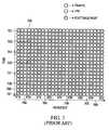
- An example of an OFDM frame format with dedicated TPS and pilot channelsis shown in FIG. 7 for the single input, single output case.
- the horizontal axis 704shows a circle representing the frequency of each of a plurality of OFDM sub-carriers.
- the vertical axis 706is time, with each row representing an OFDM symbol.
- a set of OFDM symbolsconstitutes an OFDM frame.
- the pilot channelis transmitted in a scattered manner, with the pilot symbols being transmitted every third sub-carrier, and for each sub-carrier every sixth frame.
- the first sub-carrier 700has pilot symbols 701 in the first, seventh (and so on) OFDM symbols.
- the fourth sub-carrier 702has pilot symbols 705 in the fourth, tenth (and so on) OFDM symbols.
- the third, ninth, 15 th , and 21 st sub-carriers of every OFDM symbolare used to transmit TPS symbols, collectively indicated at 708 .
- the remaining capacityis used for traffic.
- One embodiment of the inventionprovides a simple accurate and robust channel quality measurement method with broad applications such as UMTS and 3G wireless system evolution.
- a channel quality indicator(CQI) is measured indirectly, simply, and accurately, and is independent of the mobile speed, independent of multi-path channel characteristics, and avoids Walsh Code Coherent Loss.
- the CQIis a measure of the overall quality of the channel, not just one factor, such as CIR.
- the methodis easy to implement, as it does not require any additional coding, such as PN codes used in CIR measurement.
- a channel quality measurement apparatuswhich is adapted to measure a quality of a channel over which has been transmitted a sequence of symbols produced by encoding and constellation mapping a source data element sequence.
- the apparatushas a symbol de-mapper, receiving as input a sequence of received symbols over the channel whose quality is to be measured, the symbol de-mapper being adapted to perform symbol de-mapping on said sequence of received symbols to produce a sequence of soft data element decisions.
- a soft decoderreceiving as input the sequence of soft data element decisions produced by the symbol de-mapper, the soft decoder being adapted to decode the sequence of soft data element decisions to produce a decoded output sequence.
- An encoderreceives as input the decoded output sequence produced by the soft decoder, said encoder being adapted to re-encode the decoded output sequence with an identical code to a code used in encoding the source data element sequence to produce a re-encoded output sequence.
- a correlatorreceives as input the sequence of soft data element decisions produced by the de-mapper, and the re-encoded output sequence produced by the encoder, said correlator being adapted to produce a channel quality indicator output by determining a correlation between the sequence of soft data element decisions and the re-encoded output sequence.
- the symbol de-mapperis adapted to perform QPSK symbol de-mapping.
- the symbol de-mapperis adapted to perform Euclidean distance conditional LLR symbol de-mapping.
- Another broad aspect of the inventionprovides a method of measuring channel quality of a channel over which has been transmitted a sequence of symbols produced by encoding and constellation mapping a source data element sequence.
- the methodinvolves receiving a sequence of received symbols over the channel whose quality is to be measured, symbol de-mapping said sequence of received symbols to produce a sequence of soft data element decisions, decoding said sequence of soft data element decisions to produce a decoded output sequence, de-encoding said decoded output sequence to produce a re-encoded output sequence using a code identical to a code used in encoding the source data element sequence, and correlating said re-encoded output sequence, and said sequence of soft data element decisions to produce a channel quality indicator output.
- the methodis applied to measure an OFDM channel quality.
- Another broad aspect of the inventionprovides a communication system having a transmitter adapted to transmit a sequence of symbols produced by encoding and constellation mapping a source data element sequence over a channel; and a receiver having a) a symbol de-mapper, receiving as input a sequence of received symbols over the channel, said symbol de-mapper being adapted to perform symbol de-mapping on said sequence of received symbols to produce a sequence of soft data element decisions; b) a soft decoder, receiving as input the sequence of soft data element decisions produced by the symbol de-mapper, said soft decoder being adapted to decode the sequence of soft data element decisions to produce a decoded output sequence; c) an encoder, receiving as input the decoded output sequence produced by the soft decoder, said encoder being adapted to re-encode the decoded output sequence with an identical code to a code used in encoding the source data element sequence to produce a re-encoded output sequence; and d) a correlator, receiving as input the sequence of soft
- Another broad aspect of the inventionprovides a method of adaptive modulation and coding which involves transmitting over a channel a sequence of symbols produced by encoding and constellation mapping a source data element sequence, receiving a sequence of received symbols over the channel, symbol de-mapping said sequence of received symbols to produce a sequence of soft data element decisions, decoding said sequence of soft data element decisions to produce a decoded output sequence, re-encoding said decoded output sequence to produce a re-encoded output sequence using a code identical to a code used in encoding the source data element sequence, correlating said re-encoded output sequence, and said sequence of soft data element decisions to produce a channel quality indicator output, transmitting the channel quality indicator, and using said channel quality indicator to determine and apply an appropriate coding rate and modulation to the source data element sequence.
- Yet another broad aspect of the inventionprovides a method of determining a channel quality comprising correlating a soft data element decision sequence with a second data element sequence, the second data element sequence being produced by decoding the soft data element decision sequence to produce a decoded sequence and then re-encoding the decoded sequence.
- Another broad aspect of the inventionprovides a method which involves applying forward error coding to a signalling message to generate a coded fast signalling message, MPSK mapping the coded signalling message to produce an MPSK mapped coded signalling message, mapping the MPSK mapped coded signalling message onto a plurality of sub-carriers within an OFDM frame comprising a plurality of OFDM symbols, encoding symbols of the MPSK mapped coded signalling message using Differential Space-Time Block Coding (D-STBC) in a time direction to generate encoded symbols, and transmitting the encoded symbols on a plurality of transmit antennas, with the encoded symbols being transmitted at an increased power level relative to other symbols within the OFDM frame as a function of channel conditions.
- D-STBCDifferential Space-Time Block Coding
- the encoded symbolsare transmitted in a scattered pattern.
- transmitting the encoded symbols on a plurality of antennasinvolves: on a selected sub-carrier, each antenna transmitting a respective plurality N of encoded symbols over N consecutive OFDM symbols, where N is the number of antennas used to transmit, for a total of N ⁇ N transmitted encoded symbols, the N ⁇ N symbols being obtained from D-STBC encoding L symbols of the MPSK mapped coded signalling stream, where L,N determine an STBC code rate.
- the methodfurther involves transmitting a set of pilot sub-carriers in at least one OFDM symbol, and using the pilot sub-carriers as a reference for a first set of D-STBC encoded symbols transmitted during subsequent OFDM symbols.
- transmitting a set of pilot sub-carriers in at least one OFDM frameinvolves transmitting a plurality of pilots on each antenna on a respective disjoint plurality of sub-carriers.
- each disjoint plurality of sub-carrierscomprises a set of sub-carriers each separated by N ⁇ 1 sub-carriers, where N is the number of antennas.
- pilot sub-carriersare transmitted for a number of consecutive OFDM frames equal to the number of transmit antennas.
- An OFDM transmitter adapted to implement any of the above methodsis also provided.
- Another broad aspect of the inventionprovides a receiving method which involves receiving at at least one antenna an OFDM signal containing received D-STBC coded MPSK mapped coded signalling message symbols, recovering received signalling message symbols from the OFDM signal(s), re-encoding, MPSK mapping and D-STBC coding the received coded signalling message symbols to produce re-encoded D-STBC coded MPSK mapped coded signalling message symbols, and determining a channel estimate by comparing the received D-STBC coded mapped coded signalling message symbols with the re-encoded D-STBC coded MPSK mapped coded signalling message symbols.
- a channel estimateis determined for each location (in time, frequency) in the OFDM signal containing D-STBC coded MPSK mapped coded signalling message symbols.
- the methodfurther involves interpolating to get a channel estimate for remaining each location (in time, frequency) in the OFDM signal.
- the methodfurther involves receiving pilot symbols which are not D-STBC encoded which are used as a reference for a first D-STBC block of D-STBC coded MPSK mapped coded signalling message symbols.
- An OFDM receiver adapted to implement any of the above methodsis also provided.
- An article of manufacturecomprising a computer-readable storage medium is also provided, the computer-readable storage medium including instructions for implementing any of the above summarized methods.
- Another broad aspect of the inventionprovides a method of generating pilot symbols from an Orthogonal Frequency Division Multiplexing (OFDM) frame received at an OFDM receiver, the OFDM frame containing an encoded fast signalling message in the form of encoded symbols within the OFDM frame.
- the methodinvolves processing the encoded symbols based in a scattered pilot pattern to recover the encoded fast signalling message, re-encoding the fast signalling message so as to generate pilot symbols in the scattered pattern and recovering a channel response for the encoded symbols using decision feedback.
- OFDMOrthogonal Frequency Division Multiplexing
- the fast signalling messageis examined to see if the current transmission contains content for the OFDM receiver. Only if this is true is the channel response computation process continued for the current transmission.
- processing the encoded symbolsinvolves differentially decoding the encoded symbols using Differential Space-Time Block Coding (D-STBC) decoding to recover the encoded fast signalling message, applying Forward Error Correction decoding to the encoded fast signalling message to recover a fast signalling message, analyzing the fast signalling message to determine whether it includes a desired user identification and if the fast signalling message includes the desired user identification, re-encoding the fast signalling message using Forward Error Correction coding to generate the encoded fast signalling message, and re-encoding the encoded fast signalling message using D-STBC.
- D-STBCDifferential Space-Time Block Coding
- Another broad aspect of the inventionprovides a transmitter adapted to combine pilot and transmission parameter signalling on a single overhead channel within an OFDM signal.
- a set of transmission parameter signalling symbolsare transmitted on the overhead channel with strong encoding such that at a receiver, they can be decoded accurately, re-encoded, and the re-encoded symbols treated as known pilot symbols which can then be used for channel estimation.
- Another broad aspect of the inventionprovides a receiver adapted to process the combined single overhead channel produced by the above summarized transmitter.
- the receiveris adapted to decode a received signal containing the encoded transmission parameter signalling symbols as modified by a channel, re-encode the decoded symbols to produce known pilot symbols, compare received symbols with the known pilot symbols to produce a channel estimate.
- FIG. 1is a diagram of a standard carrier to interference ratio (CIR) estimator using a known channel quality measurement technique
- FIG. 2is a diagram of a channel quality indicator (CQI) estimator constructed according to an embodiment of the invention
- FIG. 3is a graph showing a QAM constellation to illustrate QPSK de-mapping according to an embodiment of the invention
- FIG. 4is a graph showing simulation results of CQI versus SNR for different Doppler frequencies
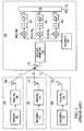
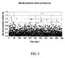
- FIG. 5is graph showing statistical results of CQI measurements
- FIG. 6is a graph showing a CDF of SNR measurement error based on the CQI
- FIG. 7is a diagram of OFDM symbol allocation for dedicated pilot and TPS channels
- FIG. 8is a block diagram of an OFDM system employing combined TPS and pilot signalling in a single overhead channel provided by an embodiment of the invention
- FIG. 9is an OFDM symbol allocation diagram showing time and frequency differentials
- FIG. 10is an example of an OFDM symbol allocation diagram showing pilot and TPS symbol locations.
- FIGS. 11 and 12are example performance results for the system of FIG. 8 .
- a measurement of the quality of the received signalis obtained by measuring a value representative of the average distance between the received signal and the reference signal constellation.
- the poorer the channelthe more scattered and random is the received signal on the reference signal constellation, and therefore the larger the average distance between the signal and its closest constellation reference point.
- the purpose of channel quality measurementis for a successful coding rate and modulation assignment.
- a “successful” assignment hereis one which achieves desired performance characteristics.
- a new channel quality measurementreferred to herein as the “Channel Quality Indicator” (CQI) is provided.
- the CQIprovides an overall assessment of the quality of the channel, including the effects of interference, multi-path fading, and Doppler spread.
- a soft output from a de-mapping functionis used to obtain a measurement of channel quality, since the amplitude of the soft output can be used as an indication of the confidence of the signal. If the channel quality is high, the soft output value will be high, and vice versa. All the channel impairments will be reflected in such an indicator, independent of their source and character. This has been demonstrated by simulation results, which show that such an indicator is invariant to the interference, multi-path fading and Doppler spread.
- the preferred embodiment presentedis based on an MIMO-OFDM frame structure in which a QAM constellation is employed, and provides an indirect channel quality measurement approach based on soft QAM demodulation and de-mapping.
- embodiments of the inventionprovide for any frame structure which employs a method of modulation and mapping having an associated reference symbol constellation which can be used in soft demodulation and de-mapping such as PSK (phase shift keying) and PAM (pulse amplitude modulation) to name a few examples.
- PSKphase shift keying
- PAMpulse amplitude modulation
- a signal from a second base transceiver station 210is a desired signal whose associated channel quality is to be measured by a mobile station 230 , and that signals from two other (first and third) base stations 200 , and 220 , can be considered to be noise by mobile station 230 .
- the second BTS 210encodes an input sequence 213 (assumed to be a sequence of bits, but more generally a sequence of data elements) at ENCODER- 2 212 to produce an encoded bit sequence.
- the encoded bit sequencecontains redundancy which allows some error detection/correction at the receiver.
- the encoded bit sequenceis then mapped to constellation points with symbol mapper 214 . These constellation points are modulated and transmitted as a signal whose associated channel quality is to be measured.
- the signalis transmitted through an antenna 218 to a mobile station 230 .
- the modulation type (and associated constellation) and type of coding employed by ENCODER- 2 212are both adaptively selected as a function of a channel quality indicator fed back from the mobile station 230 .
- the first BTS 200encodes with ENCODER- 1 202 and maps with symbol mapper 204 to produce a signal, which appears as a first interference signal to the mobile station 230 .
- This signalis transmitted through an antenna 208 .
- the third BTS 220encodes with ENCODER- 3 222 and maps with symbol mapper 224 to produce a signal which appears as a second interference signal to the mobile station 230 .
- This signalis transmitted through an antenna 228 . All three channels transmitted by antennas 208 , 218 , and 228 are received by the mobile station 230 at the receiver front-end 234 through antenna 232 , although in this example, the signal from the second base transceiver station 210 is the desired signal.
- the received signalis then passed to a symbol de-mapper 236 .
- the symbol de-mapper 236takes raw symbol data from the receiver front end 234 and de-maps the raw symbol data taking into account the known signal constellation used at the transmitting base station 210 to produce a soft bit decision sequence.
- the de-mapped symbols(soft bit decisions) inherently constitute a representation of confidence, and are used as inputs to a soft decoder 238 .
- the symbol de-mapper 236outputs a de-mapped output signal at output 237 both to the soft decoder 238 and to a correlator 250 .
- the soft decoder 238performs soft decoding on the de-mapped output signal and outputs a soft decoded output signal to an encoder 240 .
- the soft decoded outputis also output at 239 as a receiver output, this being the best available estimate at the receiver of input sequence 213 .
- a different receiver structuremay be used to generate a receiver output.
- the encoder 240re-encodes the output of the soft decoder to produce an encoded output signal and outputs this encoded output signal from output 242 to a correlator 250 .
- the same encodingis used as was employed at ENCODER- 2 212 of the base station 210 . Assuming proper decoding and re-encoding, the output of the encoder 240 is the same as the encoded sequence produced by the encoder 212 at the base transceiver station 210 .
- the correlator 250correlates the re-encoded sequence from the encoder output 242 , with the de-mapped output signal (soft bit decision sequence) from the symbol de-mapper output 237 .
- the correlator 250outputs this correlation as a channel quality indicator (CQI).
- CQIchannel quality indicator
- correlator 250multiplies the re-encoded bit sequence 242 with the soft bit decision sequence with multiplier 251 . These are summed with summer 252 , and then the square absolute value is taken as indicated at 253 .
- Other methods of correlatingmay be employed.
- the symbol de-mapper 236takes the input from the receiver front end 234 , and performs de-mapping based on Euclidean distance.
- the preferred embodimentis described in the context of QPSK de-mapping, which is a special case of PSK de-mapping.
- PSK de-mappingthere are two types of de-mapping methods based on whether or not the PSK signals have been normalized.
- the optimum de-mappingis based on Euclidean distance; while for non-coherent de-mapping, which is often the case when differential encoding is used, de-mapping can only be based on angle.
- the de-mapping-based-on-angle methodis a sub-optimum one, as it ignores the information carried in the amplitude of a signal.
- QPSK de-mappingdoes not depend upon signal normalization.
- QPSK de-mappingis based on an LLR (logarithm of likelihood ratio) and in this example, as described with reference to FIG. 3 , uses Euclidean distance.
- the constellation depicted in FIG. 3is a QPSK constellation with Grey mapping.
- Point (x,y)represents the signal input from the receiver front end 234 .
- the soft de-mapped bits b 1 b 2 using Euclidean distance LLRcan be expressed as:
- h n,mare elements of an MIMO (Multiple Input Multiple Output) channel matrix.
- the noise variances of the four channelsare the same, i.e., ⁇ 2 , then the noise power becomes ( ⁇ / ⁇ ) 2 .
- b 1 with STBCis
- conditional LLR soft de-mapped bits b 1 b 2are output to the soft decoder 238 which uses the de-mapped bits, and takes into account the data stream history information, the encoding algorithm which was used in Encoder- 2 212 , to make a best estimate of the original unencoded code word.
- This best estimate which is output from the soft decoder 238is re-encoded by encoder 240 using the same encoding algorithm as encoder- 2 212 .
- the re-encoded code wordis output from encoder output 242 , to the correlator 250 .
- the correlator 250correlates the conditional LLR output from output 237 of the symbol de-mapper 236 , with the re-encoded code word output from output 242 of the encoder 240 .
- the act of correlationprojects the conditional LLR onto the re-encoded code word, the result of which is an inner product output which is used as the Channel Quality Indicator (CQI).
- CQIChannel Quality Indicator
- the CQIbecause it is a measure of the correlation between the symbol de-mapper output and the re-encoded sequence, indicates the channel distortion.
- the use of the likelihood valuerelies neither on the code type (block code, convolutional code, or turbo code), nor on the decoding method (hard or soft), and does not distinguish where the interference originates, e.g., neighboring-cell interference, white thermal noise, or residual Doppler shift.
- the CQIuses all the information available for the estimation, not only the values of the de-mapped output, but the likelihood of being a code word as well, which is much more accurate than measuring soft output value alone, especially when the code rate is low. In FIG.
- coded transmit datais used at a receiver to generate a channel quality indicator for use in making adaptive coding and modulation decisions.
- a methodis provided of combining pilot symbols with Transmit Parameter Signalling (TPS) symbols within an Orthogonal Frequency Division Multiplexing (OFDM) frame in such a manner that channel estimation can still be performed.
- the methodmay be implemented at a SISO (single-input single-output) transmitter or implemented at a Multiple-Input Multiple-Output (MIMO) OFDM transmitter, and can be described broadly as four steps.
- a fast signalling messageis forward error coding (FEC) encoded to generate a coded fast signalling message.
- FECforward error coding
- the coded fast signalling messageis mapped onto symbols within the OFDM frame.
- the symbolsare encoded using Differential Space-Time Block Coding (D-STBC) to generate encoded symbols.
- D-STBCDifferential Space-Time Block Coding
- the D-STBC codingis preferably applied in the time direction of the OFDM frame, as the channel response of the channel over which scattered pilot sub-carriers are transmitted will usually vary more rapidly with frequency direction than with time direction, and so differential decoding at the OFDM receiver is more likely to yield a better estimate of the channel response if the differential decoding is with respect to symbols distributed along the time direction.
- the encoded symbolsare transmitted in a scattered pilot pattern at an increased power level relative to other traffic data symbols within the OFDM frame. In some embodiments, the power level is only increased relative to other traffic data symbols if channel conditions are poor.
- the methodallows fast signalling messages to be used as pilot symbols, thereby reducing overhead within the OFDM frame.
- a method of extracting pilot symbols from an OFDM frame in which the pilot symbols have been combined with TPS symbols, as described above,is also provided.
- the methodis implemented at a MIMO OFDM receiver when an OFDM frame containing encoded symbols is received at the OFDM receiver, and can be described broadly as eight steps.
- the OFDM receiverrecovers the encoded symbols based on the scattered pattern to recover the D-STBC blocks.
- the OFDM receiverdifferentially decodes the recovered D-STBC blocks using D-STBC decoding to recover the FEC encoded fast signalling message.
- the OFDM receiverapplies FEC decoding to the FEC encoded fast signalling message to recover the fast signalling message.
- the OFDM receiveranalyzes the fast signalling message to determine whether it includes a desired user identification.
- the OFDM receiverknows that the current TPS frame contains data for the user and continues processing the OFDM frame. As a fifth step, the OFDM receiver re-encodes the fast signalling message using FEC coding. Sixth, the OFDM receiver re-encodes the encoded fast signalling message using D-STBC encoding. If the fast signalling message does not include the receiver's user identification, then power can be saved by not proceeding to conduct the rest of the channel estimation steps.
- a channel response for the D-STBC encoded symbolcan be obtained by comparing the known transmitted pilots (re-encoded TPS data) with the received signals.
- a channel responseis obtained for each TPS insertion point.
- the channel responses thus determinedcan then be used to interpolate a channel response for every traffic data symbol, at all times and frequencies, within the OFDM frame. Preferably, this is done by performing a 2-dimensional interpolation (in time direction and frequency direction) to generate channel estimate for some points where TPS were not inserted. This is followed by an interpolation in frequency to generate a channel estimate for every sub-carrier of OFDM symbols containing TPS data.
- every OFDM symbolcontains some TPS insertion points and as such this completes the interpolation process. In other embodiments, there are some OFDM symbols which do not have any TPS insertion points. To get channel estimates for these OFDM symbols, an interpolation in time of the previously computed channel estimates is performed. In high mobility applications, TPS should be included in every OFDM symbol avoiding the need for this last interpolation in time step.
- a fast algorithmmay be applied at the OFDM receiver when computing a Discrete Fourier Transform based on the scattered pattern in order to extract the combined pilot and fast signalling message. This reduces power consumption at the OFDM receiver.
- the inventionhas been described with respect to a MIMO-OFDM communication system.
- the inventionmay also be used in a single transmitter OFDM communication system, but will be of less advantage as the number of pilot symbols transmitted as overhead is more manageable than in MIMO OFDM communication systems.
- the method of combining pilot symbols with the TPS channels and the method of extracting pilot symbolsare preferably implemented on an OFDM transmitter and on an OFDM receiver respectively in the form of software instructions readable by a digital signal processor.
- the methodsmay be implemented as logic circuitry within an integrated circuit. More generally, the methods may be implemented by any computing apparatus containing logic for executing the described functionality.
- the computing apparatus which implements the methodsmay be a single processor, more than one processor, or a component of a larger processor.
- the logicmay comprise external instructions stored on a computer-readable medium, or may comprise internal circuitry.
- D-STBCis preferable for high mobility application.
- a preferred D-STBC schemeis shown in FIG. 8 and described in detail below.
- the channel variation between two coded symbolsshould be sufficiently small.
- the channel variation along the frequency axisrepresents the multi-path channel induced frequency selectivity
- the channel variation along the time axisrepresents the temporal fading variation.
- the differential encoding directionshould be optimized.
- phase shift between two adjacent pilotscould be very large, for example, for the ITU Vehicular A channel, if the two pilot blocks are 16 bins apart, then the phase shift of the channel between the two positions can be as high as ⁇ , which makes differential decoding impossible.
- the span of pilots in the frequency domainmust be reduced. However, this will further increase the pilot overhead.
- Differential in timeis limited by Doppler frequency caused by high-speed mobility.
- Doppler frequencycaused by high-speed mobility.
- the channel variation along the time directionvaries much slower than along the frequency direction, therefore, D-STBC should preferably be encoded along time direction.
- a pair of the STBC encoded TPS symbolsare allocated on the same frequency index (sub-carrier) of two adjacent OFDM symbols.
- the two possible differentialsare shown in FIG. 9 .
- Differential in time encodingis generally indicated by 900 and differential in frequency encoding is generally indicated by 902 .
- FEC encodingis preferably applied to TPS data, since the decoding of the TPS data is critical for configuring the receiver to detect the traffic data correctly and for the correct re-encoding of the TPS data so as to allow an accurate decision feedback to reliably convert the TPS into a scattered pilot.
- a ( 32 , 6 ) Hadamard codemight for example be used. However, the code selection is not limited to this code alone.
- pilot channel OFDM symbolsare periodically inserted in the OFDM symbols.
- FIG. 10An example of this is shown in FIG. 10 where pilot symbols are inserted in every sub-carrier periodically, for example 2 pilot channel OFDM symbols for every 20 OFDM symbols.
- the pilot symbols transmitted on the pilot channel OFDM symbolsare preferably sent only by one antenna at a time for a given frequency.
- the pilot symbolsmay alternate in frequency between the first and second antenna. This is shown in FIG. 10 where two OFDM symbols 910 , 912 are used to transmit pilot symbols, and every odd sub-carrier is used for the first antenna, and every even sub-carrier is used for the second antenna. These pilot symbols may then be used as a reference for subsequent D-STBC symbols.
- interpolationcan be performed to obtain pilot information for the intervening non-transmitted sub-carriers. Thus, interpolation is performed for the even sub-carriers for the first transmitter, and interpolation is performed for the odd sub-carriers for the second transmitter.
- the channel information obtained from the pilot headeris then used to decode the first blocks of TPS. Since the pilot header is transmitted periodically, the D-STBC encoder is also reset at the same frequency. After the first blocks of TPS are processed, the user has also obtained the first blocks of D-STBC references. In addition, the resetting of D-STBC encoder by periodic pilot headers prevents error propagation in the decision-feedback channel estimation process.
- FIG. 10also shows the example locations of TPS symbols and of data symbols.
- the first two OFDM symbols 910 , 912 of every 20 symbol cyclecontain pilot symbols as discussed above.
- the third through 20 th framescontain TPS or data.
- a diamond lattice patternis used for TPS symbols, with every third sub-carrier containing TPS symbols, alternating between three sets of two TPS symbols on the first, seventh, thirteenth, nineteenth and twenty-fifth sub-carriers 914 , 916 , 918 , 920 , 922 , and two sets of two TPS symbols on the fourth, tenth, sixteenth and twenty-second sub-carriers 924 , 925 , 926 , 928 .
- TPS datais transmitted all of the antennas, (i.e. by both antennas in our example).
- the TPS data transmitted on the two antennascollectively forms a common TPS channel.
- FIG. 11shows TPS bit error rate versus SNR curves for various Doppler frequencies. As we can see from the figure, it is very robust to Doppler spread.
- FIG. 12shows the simulation results for traffic channel based on TPS assisted channel estimation. From this figure, it can be seen that the degradation due to TPS decoding error is negligible.
- D-STBCinvolves the recursive computing of a transmission matrix.
- differentiatedit is meant the current transmitted D-STBC block is the matrix product operation between the previously transmitted D-STBC block and the current STBC block input.
- TPS datais transmitted on two consecutive OFDM symbols for the same sub-carrier for a set of sub-carriers which may change from one set of two OFDM symbols to another set of two OFDM symbols. More generally, for a MIMO system with N antennas, TPS data is transmitted over N consecutive OFDM frames for the same sub-carrier.
- the actual amount L of TPS data transmitteddepends on the D-STBC code rate. For example, if there are four antennas, then a 4 ⁇ 4 STBC matrix is obtained from encoding three symbols from the MPSK mapped TPS signalling stream.
- the first sub-carrier transmitted by both antennaswill contain TPS data on the third, fourth, ninth, tenth, and 15 th , 16 th frames.
- the datawill be both time and space differentially encoded meaning that there is information both in the difference between symbols sent at different times (differential time), and in the difference between symbols sent on different antennas (differential space).
- the first and second pilot symbols 930 (frame 910 ) and 932 (frame 912 ) transmitted by the first antenna on the first sub-carrier and an interpolated value for the first pilot and second pilot symbols transmitted by the second antenna on the first sub-carriercollectively provide a reference for the first two TPS symbols 934 , 936 transmitted by the two antennas. Subsequent TPS symbols rely on previously transmitted TPS symbols as references.
- the forward error corrected TPS data to be transmitted on a given sub-carrieris indicated as a sequence ⁇ C 1 , C 2 . . . ⁇ 950 , assumed to be M-ary in nature.
- Thisis M-PSK mapped at 952 .
- M-PSK symbolsare then processed pairwise (for the 2 ⁇ 2 case) with a pair of M-PSK symbols at time i being referred to as ⁇ x 1,i, x 2,i ⁇ .
- Space time block codingproduces a 2 ⁇ 2 STBC matrix H x,i 954 which contains x 1,i , x 2,i in a first column and ⁇ x 2,i *, x 1,i * in the second column.
- the STBC block index iincrements once every 2 OFDM symbols.
- the output of the encoder at time iis identified as H z,i , 956 with the output at time i ⁇ 1 identified as H z,i ⁇ 1 stored in delay element 958 .
- H z,ihas the same structure as H x,i .
- the following encoder equationcan be obtained for the output as a function of the input:
- H z , i1 E x ⁇ H x , i ⁇ H z , i - 1
- H z,ithe D-STBC matrix at STBC block index i
- H x,ithe STBC input matrix at STBC block index i
- E xis the energy of each signal in H x,i .
- the output H z,iis a 2 ⁇ 2 matrix having four elements with the first row of the elements being transmitted on one antenna 960 , and second row of the elements being transmitted on the other antenna 962 .
- the matrix H z,iis transmitted collectively by the two antennas during TPS symbol locations 934 , 936 of the first sub-carrier using the pilot symbols as the reference.
- y 1 (m)is the received signal over two OFDM frames for STBC block index i
- H x,iis the STBC block input at STBC block index i
- E xis the energy of signal elements in H x,i
- a 1,iis the channel matrix for receive antenna 1 representing the channel response h 11 from first transmit antenna to the receive antenna and h 21 for the second transmit antenna to the receive antenna at STBC block index i
- H z,iis the transmitted D-STBC block
- the decoding of differentially encoded STBC codecan be simplified into one step even simpler than STBC decoding itself, considering that there is no channel estimation is needed. Note that all the calculation here is carried out in the frequency domain, therefore, the relation between the transmitted signal and the channel is multiplication, rather than convolution.
- channel parameters for each pathcan only be estimated through re-encoding the decoded data, after TPS have been successfully decoded. This decision-feedback approach is the key in how to make use of TPS as scattered pilots.
Landscapes
- Engineering & Computer Science (AREA)
- Signal Processing (AREA)
- Computer Networks & Wireless Communication (AREA)
- Quality & Reliability (AREA)
- Power Engineering (AREA)
- Physics & Mathematics (AREA)
- Electromagnetism (AREA)
- Mobile Radio Communication Systems (AREA)
- Radio Transmission System (AREA)
- Digital Transmission Methods That Use Modulated Carrier Waves (AREA)
Abstract
Description
PNi·PNj≈0 i≠j
PNi·PNi=
This important relation that the PN codes form a near orthogonal set allows for the extraction of specific channels using the Pilot channel PN codes. In
In these equations C and I are energies although for the purposes of determining the ratio C/I, either energy or power may be used. Since the pilot header is composed of two identical OFDM symbols, the CIR calculation process can be based on the average over the two symbols, thus reducing noise. These methods, however, fail to work if the channel is a multi-path fading channel and/or mobility speed is high. One solution is to insert more pilots to improve the measurement quality, however, this introduces overhead which significantly reduces spectral efficiency. For example, in 2G and 3G wireless systems, the pilot overhead is about 20-35%, and the pilot design for these systems is not suitable for fast channel quality measurement. This is the case because fundamentally the accuracy of the channel quality measurement is limited by the Cramer-Rao lower bound, which implies that the accuracy of channel measurement can be gained only at the expense of more pilot overhead (either in time or in power).
where σ2=2ENo, and E is the energy of per QPSK symbol.
x02+y02=x12+y°12=x22+y22=x32+y32.
Then b1simplifies to:
Since x0=x1and x2=x3:
Let D be the vertical distance in the I-Q plot between S0and S1, and between S2and S3. Therefore y0−y1=y2−y3=D, and:
Because of the symmetry of the constellation x3−x1=−D. Since y1=y3, b1can be expressed as:
Similarly, b2is expressed as:
If the noise is fixed, then the QPSK de-mapping algorithm can be simplified further to:
b1=−x
b2=−y,
This is equivalent to two BPSK signals and is very easy to compute.
This verifies therefore that QPSK in STBC de-mapping is not affected by different scaling factors used in normalization. The conditional LLR soft de-mapped bits b1b2are output to the
- 1. Differential direction,
- 2. Data protection,
- 3. Initialization/reset.
Differential Direction
where Hz,iis the D-STBC matrix at STBC block index i, Hx,iis the STBC input matrix at STBC block index i, and Exis the energy of each signal in Hx,i. The output Hz,iis a 2×2 matrix having four elements with the first row of the elements being transmitted on one
where y1(m), y1(m+1) is the received signal over two OFDM frames for STBC block index i, Hx,iis the STBC block input at STBC block index i, Exis the energy of signal elements in Hx,i, A1,iis the channel matrix for receive
From the equation
we can obtain Hx,ifrom the four consecutively received signals y1(m−2), y1(m−1), y1(m), y1(m+1). Note that in the case of multiple receiver antennas, the same expression holds true for each antenna. Since D-STBC works on STBC blocks, it also has the same soft failure property as STBC, i.e., the system will not break down due to transmitting antennas failure—as long is still at least one antenna working. In addition, the code design for MIMO channel is in fact a task for STBC, and is irrelevant to D-STBC. Therefore, D-STBC can be easily expanded to the case with transmitter diversity of order more than 2.
Other System Design Considerations
Encoding
The above equation is the only operation needed for D-STBC encoder, where no matrix operation is involved. One row of the resultant matrix Hz,i, namely z1,i, z2,iis transmitted by one antenna, and the other row, namely −z*2,i, z*1,iis transmitted by the other antenna.
Decoding
- m: OFDM symbol index in time
- i: OFDM channel estimation index=2m
- k: OFDM sub-carrier index
- x1,i: first PSK symbol to form STBC block Hx,i
- x2,i: second PSK symbol to form STBC block Hx,i
- yj(m): received signal at antenna j=1, 2
The transmitted STBC coded signal (i.e., before the differential encoder) at time m and m+1 is:
- where the column number is in space domain, while the row number is in time domain. Note the relationship hold true on a per sub-carrier basis.
From the above two equations, the maximum likelihood signals of x1,iand x2,ican be obtained as:
{tilde over (x)}1,i=y1(m−2)*y1(m)+y1(m−1)y1(m+1)*+y2(m−2)*y2(m)+y2(m−2)y2(m+1)*
{tilde over (x)}2,i=y1(m−1)*y1(m)−y1(m−2)y1(m+1)*+y2(m−1)*y2(m)−y2(m−2)y2(m+1)*
or in a matrix form:
It is the above matrix equation is depicted in block diagram form in the receiver path of
Channel Estimation
By solving the above equation, we get
where
δ2=|z1,i|2+z2,i|2.
In a similar way, we can estimate h12(m,k) and h22(m,k) from the signals received at receiver antenna2:
It needs to be noticed that for each STBC block, we can only obtain one set of channel information for the current time, with the assumption that the channel will approximately be the same during this period. As pointed out earlier, this condition can be easily satisfied. Again, all of this is done for each sub-carrier used to transmit STBC blocks of pilot /TPS data.
Claims (17)
Priority Applications (13)
| Application Number | Priority Date | Filing Date | Title |
|---|---|---|---|
| US10/038,916US7773699B2 (en) | 2001-10-17 | 2002-01-08 | Method and apparatus for channel quality measurements |
| EP10184513.9AEP2264927B1 (en) | 2001-10-17 | 2002-10-15 | Method and apparatus for channel quality measurements |
| AU2002331504AAU2002331504A1 (en) | 2001-10-17 | 2002-10-15 | Method and apparatus for channel quality measurements |
| PCT/CA2002/001543WO2003034646A2 (en) | 2001-10-17 | 2002-10-15 | Method and apparatus for channel quality measurements |
| CNB02825273XACN100420178C (en) | 2001-10-17 | 2002-10-15 | Channel quality measuring method and device, communication system, adaptive modulation and coding method |
| EP02767022AEP1438800A2 (en) | 2001-10-17 | 2002-10-15 | Method and apparatus for channel quality measurements |
| EP10184538AEP2264928A3 (en) | 2001-10-17 | 2002-10-15 | Method and apparatus for channel quality measurements |
| CN2008101442780ACN101355405B (en) | 2001-10-17 | 2002-10-15 | Method and apparatus for channel quality measurements, communication system, self-adapting modulating and encoding method |
| KR1020047005680AKR100964203B1 (en) | 2001-10-17 | 2002-10-15 | Method and device for measuring channel quality |
| KR1020107002306AKR101020461B1 (en) | 2001-10-17 | 2002-10-15 | Method and device for measuring channel quality |
| HK09105069.6AHK1127678B (en) | 2001-10-17 | 2009-06-05 | Method and apparatus for channel quality measurements, communication system, and method of adaptive modulation and coding |
| US12/839,836US8170155B2 (en) | 2001-10-17 | 2010-07-20 | Method and apparatus for channel quality measurements |
| US13/437,066US8594247B2 (en) | 2001-10-17 | 2012-04-02 | Method and apparatus for channel quality measurements |
Applications Claiming Priority (3)
| Application Number | Priority Date | Filing Date | Title |
|---|---|---|---|
| US32951501P | 2001-10-17 | 2001-10-17 | |
| US32951101P | 2001-10-17 | 2001-10-17 | |
| US10/038,916US7773699B2 (en) | 2001-10-17 | 2002-01-08 | Method and apparatus for channel quality measurements |
Related Child Applications (1)
| Application Number | Title | Priority Date | Filing Date |
|---|---|---|---|
| US12/839,836ContinuationUS8170155B2 (en) | 2001-10-17 | 2010-07-20 | Method and apparatus for channel quality measurements |
Publications (2)
| Publication Number | Publication Date |
|---|---|
| US20030072395A1 US20030072395A1 (en) | 2003-04-17 |
| US7773699B2true US7773699B2 (en) | 2010-08-10 |
Family
ID=27365471
Family Applications (3)
| Application Number | Title | Priority Date | Filing Date |
|---|---|---|---|
| US10/038,916Active2028-08-12US7773699B2 (en) | 2001-10-17 | 2002-01-08 | Method and apparatus for channel quality measurements |
| US12/839,836Expired - Fee RelatedUS8170155B2 (en) | 2001-10-17 | 2010-07-20 | Method and apparatus for channel quality measurements |
| US13/437,066Expired - LifetimeUS8594247B2 (en) | 2001-10-17 | 2012-04-02 | Method and apparatus for channel quality measurements |
Family Applications After (2)
| Application Number | Title | Priority Date | Filing Date |
|---|---|---|---|
| US12/839,836Expired - Fee RelatedUS8170155B2 (en) | 2001-10-17 | 2010-07-20 | Method and apparatus for channel quality measurements |
| US13/437,066Expired - LifetimeUS8594247B2 (en) | 2001-10-17 | 2012-04-02 | Method and apparatus for channel quality measurements |
Country Status (6)
| Country | Link |
|---|---|
| US (3) | US7773699B2 (en) |
| EP (3) | EP2264928A3 (en) |
| KR (2) | KR100964203B1 (en) |
| CN (2) | CN100420178C (en) |
| AU (1) | AU2002331504A1 (en) |
| WO (1) | WO2003034646A2 (en) |
Cited By (16)
| Publication number | Priority date | Publication date | Assignee | Title |
|---|---|---|---|---|
| US20080063079A1 (en)* | 2006-09-12 | 2008-03-13 | Wang Zhongjun | Apparatus and method for receiving digital video signals |
| US20090149140A1 (en)* | 2006-01-05 | 2009-06-11 | Borran Mohammad J | Power control utilizing multiple rate interference indications |
| US20090316830A1 (en)* | 2005-08-24 | 2009-12-24 | Hermann Rohling | Method and transmitting device for encoding data in a differential space-time block code |
| US20120120942A1 (en)* | 2009-06-19 | 2012-05-17 | Sharp Kabushiki Kaisha | Wireless communication system, transmitter and wireless communication method |
| US20130022058A1 (en)* | 2010-04-07 | 2013-01-24 | Hiroyuki Akutagawa | Transmitter and transmission method |
| US8619891B2 (en) | 2005-08-23 | 2013-12-31 | Apple Inc. | Adaptive two-dimensional channel interpolation |
| US8681627B2 (en) | 2010-12-07 | 2014-03-25 | Sharp Kabushiki Kaisha | Prioritizing multiple channel state information (CSI) reporting with carrier aggregation |
| US20140301220A1 (en)* | 2004-06-30 | 2014-10-09 | Neocific, Inc. | Method and apparatus for interference control in a multi-cell communication system |
| CN104205703A (en)* | 2012-04-10 | 2014-12-10 | 高通股份有限公司 | Systems and methods for wireless communication of long data units |
| US8995402B2 (en) | 2004-03-15 | 2015-03-31 | Apple Inc. | Pilot design for OFDM systems with four transmit antennas |
| US9154471B2 (en) | 2013-11-26 | 2015-10-06 | At&T Intellectual Property I, L.P. | Method and apparatus for unified encrypted messaging |
| US9432162B2 (en) | 2006-01-20 | 2016-08-30 | Blackberry Limited | Methods and systems for scheduling a virtual MIMO communication environment |
| US9893851B2 (en) | 2005-02-22 | 2018-02-13 | Texas Instruments Incorporated | Turbo HSDPA system |
| US9930677B2 (en) | 2010-12-07 | 2018-03-27 | Sharp Kabushiki Kaisha | Prioritizing multiple channel state information (CSI) reporting with carrier aggregation |
| US10348542B2 (en) | 2005-08-23 | 2019-07-09 | Apple Inc. | Pilot symbol patterns for transmission through a plurality of antennas |
| US20240340047A1 (en)* | 2021-12-30 | 2024-10-10 | Vivo Mobile Communication Co., Ltd. | Decoding method, device, and readable storage medium |
Families Citing this family (204)
| Publication number | Priority date | Publication date | Assignee | Title |
|---|---|---|---|---|
| US7295509B2 (en) | 2000-09-13 | 2007-11-13 | Qualcomm, Incorporated | Signaling method in an OFDM multiple access system |
| US9130810B2 (en) | 2000-09-13 | 2015-09-08 | Qualcomm Incorporated | OFDM communications methods and apparatus |
| US6810236B2 (en) | 2001-05-14 | 2004-10-26 | Interdigital Technology Corporation | Dynamic channel quality measurement procedure for adaptive modulation and coding techniques |
| US7773699B2 (en)* | 2001-10-17 | 2010-08-10 | Nortel Networks Limited | Method and apparatus for channel quality measurements |
| US7245598B2 (en)* | 2002-02-21 | 2007-07-17 | Qualcomm Incorporated | Feedback of channel quality information |
| US7986672B2 (en)* | 2002-02-25 | 2011-07-26 | Qualcomm Incorporated | Method and apparatus for channel quality feedback in a wireless communication |
| JP4078848B2 (en)* | 2002-02-26 | 2008-04-23 | Kddi株式会社 | Adaptive coding method and transmitter using space-time block code |
| JP3691449B2 (en)* | 2002-03-25 | 2005-09-07 | 三洋電機株式会社 | Diversity circuit and diversity receiver including the circuit |
| US6898757B1 (en)* | 2002-04-04 | 2005-05-24 | Legend Silicon Corporation | Decoding multi-block product code |
| US6829470B2 (en)* | 2002-04-08 | 2004-12-07 | Lucent Technologies Inc. | Per stream rate control using APP decoding |
| US6801580B2 (en)* | 2002-04-09 | 2004-10-05 | Qualcomm, Incorporated | Ordered successive interference cancellation receiver processing for multipath channels |
| EP1518343A1 (en)* | 2002-06-21 | 2005-03-30 | Telefonaktiebolaget LM Ericsson (publ) | Generation of orthogonal codes |
| US7460607B2 (en)* | 2002-06-26 | 2008-12-02 | Broadcom Corporation | Method and apparatus for space-time turbo-coded modulation |
| US8194770B2 (en) | 2002-08-27 | 2012-06-05 | Qualcomm Incorporated | Coded MIMO systems with selective channel inversion applied per eigenmode |
| US7324429B2 (en) | 2002-10-25 | 2008-01-29 | Qualcomm, Incorporated | Multi-mode terminal in a wireless MIMO system |
| US8570988B2 (en) | 2002-10-25 | 2013-10-29 | Qualcomm Incorporated | Channel calibration for a time division duplexed communication system |
| US8170513B2 (en) | 2002-10-25 | 2012-05-01 | Qualcomm Incorporated | Data detection and demodulation for wireless communication systems |
| US20040081131A1 (en) | 2002-10-25 | 2004-04-29 | Walton Jay Rod | OFDM communication system with multiple OFDM symbol sizes |
| US7002900B2 (en) | 2002-10-25 | 2006-02-21 | Qualcomm Incorporated | Transmit diversity processing for a multi-antenna communication system |
| US8320301B2 (en) | 2002-10-25 | 2012-11-27 | Qualcomm Incorporated | MIMO WLAN system |
| US8208364B2 (en)* | 2002-10-25 | 2012-06-26 | Qualcomm Incorporated | MIMO system with multiple spatial multiplexing modes |
| US7986742B2 (en) | 2002-10-25 | 2011-07-26 | Qualcomm Incorporated | Pilots for MIMO communication system |
| US8134976B2 (en)* | 2002-10-25 | 2012-03-13 | Qualcomm Incorporated | Channel calibration for a time division duplexed communication system |
| US8218609B2 (en) | 2002-10-25 | 2012-07-10 | Qualcomm Incorporated | Closed-loop rate control for a multi-channel communication system |
| US8169944B2 (en) | 2002-10-25 | 2012-05-01 | Qualcomm Incorporated | Random access for wireless multiple-access communication systems |
| KR100542090B1 (en)* | 2002-12-16 | 2006-01-11 | 한국전자통신연구원 | Error control method, wireless access control frame design method, terminal registration method and recording medium in wireless communication system |
| JP4256158B2 (en)* | 2002-12-26 | 2009-04-22 | パナソニック株式会社 | Wireless communication apparatus and wireless communication method |
| US7280467B2 (en) | 2003-01-07 | 2007-10-09 | Qualcomm Incorporated | Pilot transmission schemes for wireless multi-carrier communication systems |
| DE10304751A1 (en)* | 2003-02-05 | 2004-08-26 | Siemens Ag | Multiple carrier radio data transmission procedure for FDM mobile radio data systems uses known symbol coded at maximum power at known positions for channel estimation |
| US7379417B2 (en)* | 2003-02-19 | 2008-05-27 | Wipro Limited | Orthogonal frequency division multiplexing transmitter system and VLSI implementation thereof |
| FR2853182B1 (en)* | 2003-03-25 | 2005-06-17 | Thales Sa | METHOD FOR INCREASING THE CAPACITY OF A TRANSMISSION SYSTEM USING WAVEFORMS |
| US7593363B2 (en) | 2003-05-06 | 2009-09-22 | Nokia Siemens Networks Gmbh & Co. Kg | Data transmission method |
| DE10320156A1 (en)* | 2003-05-06 | 2004-12-16 | Siemens Ag | Data transmission involves repeatedly sending channel quality information from receiver to transmitter if first activity state exists and time since last quality data transmission exceeds threshold |
| US8064528B2 (en) | 2003-05-21 | 2011-11-22 | Regents Of The University Of Minnesota | Estimating frequency-offsets and multi-antenna channels in MIMO OFDM systems |
| US8018902B2 (en)* | 2003-06-06 | 2011-09-13 | Telefonaktiebolaget L M Ericsson (Publ) | Methods and apparatus for channel quality indicator determination |
| CN100505677C (en) | 2003-06-19 | 2009-06-24 | 三菱电机株式会社 | Wireless base station device and mobile communication system |
| US20050025040A1 (en)* | 2003-07-29 | 2005-02-03 | Nokia Corporation | Method and apparatus providing adaptive learning in an orthogonal frequency division multiplex communication system |
| JP4734116B2 (en) | 2003-08-06 | 2011-07-27 | パナソニック株式会社 | Wireless communication apparatus and reception quality reporting method |
| US7388847B2 (en)* | 2003-08-18 | 2008-06-17 | Nortel Networks Limited | Channel quality indicator for OFDM |
| US7453946B2 (en)* | 2003-09-03 | 2008-11-18 | Intel Corporation | Communication system and method for channel estimation and beamforming using a multi-element array antenna |
| US7382719B2 (en)* | 2003-09-05 | 2008-06-03 | Texas Instruments Incorporated | Scalable and backwards compatible preamble for OFDM systems |
| KR100929094B1 (en)* | 2003-09-20 | 2009-11-30 | 삼성전자주식회사 | System and method for dynamic resource allocation in a communication system using orthogonal frequency division multiple access scheme |
| US7616698B2 (en) | 2003-11-04 | 2009-11-10 | Atheros Communications, Inc. | Multiple-input multiple output system and method |
| US9473269B2 (en) | 2003-12-01 | 2016-10-18 | Qualcomm Incorporated | Method and apparatus for providing an efficient control channel structure in a wireless communication system |
| US7016297B2 (en)* | 2003-12-10 | 2006-03-21 | Clive K Tang | Method and apparatus providing decentralized, goal-orientated adaptive learning in an adaptive orthogonal frequency division multiplex communication system |
| EP1542488A1 (en)* | 2003-12-12 | 2005-06-15 | Telefonaktiebolaget LM Ericsson (publ) | Method and apparatus for allocating a pilot signal adapted to the channel characteristics |
| US20050190800A1 (en)* | 2003-12-17 | 2005-09-01 | Intel Corporation | Method and apparatus for estimating noise power per subcarrier in a multicarrier system |
| KR100981580B1 (en)* | 2003-12-23 | 2010-09-10 | 삼성전자주식회사 | Differential Space-Time Block Code Transceiver Using Up to Eight Transmit Antennas |
| ES2885101T3 (en) | 2004-01-29 | 2021-12-13 | Neo Wireless Llc | Procedures and apparatus for superimposing direct sequence and multi-carrier spread spectrum signals in a broadband wireless communication system |
| US7756003B1 (en) | 2004-02-27 | 2010-07-13 | Marvell International Ltd. | Adaptive OFDM transmitter based on carrier frequency offset |
| MXPA06010110A (en) | 2004-03-05 | 2007-03-07 | Nextnet Wireless Inc | System and method for adaptive modulation. |
| EP1583277A1 (en)* | 2004-03-31 | 2005-10-05 | Infineon Technologies AG | MIMO-OFDM backward-compatible transmission system |
| US8958493B2 (en) | 2004-03-31 | 2015-02-17 | Infineon Technologies Ag | Operation for backward-compatible transmission |
| JP4750373B2 (en)* | 2004-04-28 | 2011-08-17 | 株式会社エヌ・ティ・ティ・ドコモ | Radio control apparatus, mobile communication system, and communication control method |
| US8014264B2 (en) | 2004-05-01 | 2011-09-06 | Neocific, Inc. | Methods and apparatus for communication with time-division duplexing |
| KR100635533B1 (en)* | 2004-05-07 | 2006-10-17 | 전자부품연구원 | Method and apparatus for detecting STC-OPEM signal in time-varying channel |
| CN100359959C (en) | 2004-06-01 | 2008-01-02 | 华为技术有限公司 | A Method for Realizing Channel Estimation in Orthogonal Multiplex Frequency Division Multiplexing System |
| KR20070034003A (en)* | 2004-06-21 | 2007-03-27 | 코닌클리케 필립스 일렉트로닉스 엔.브이. | Datastream Modulation with Constellation Subset Mapping |
| EP1766806B1 (en)* | 2004-06-22 | 2017-11-01 | Apple Inc. | Closed loop mimo systems and methods |
| WO2006002550A1 (en)* | 2004-07-07 | 2006-01-12 | Nortel Networks Limited | System and method for mapping symbols for mimo transmission |
| US8000221B2 (en) | 2004-07-20 | 2011-08-16 | Qualcomm, Incorporated | Adaptive pilot insertion for a MIMO-OFDM system |
| US9137822B2 (en)* | 2004-07-21 | 2015-09-15 | Qualcomm Incorporated | Efficient signaling over access channel |
| US9148256B2 (en) | 2004-07-21 | 2015-09-29 | Qualcomm Incorporated | Performance based rank prediction for MIMO design |
| US7864659B2 (en)* | 2004-08-02 | 2011-01-04 | Interdigital Technology Corporation | Quality control scheme for multiple-input multiple-output (MIMO) orthogonal frequency division multiplexing (OFDM) systems |
| KR100719339B1 (en)* | 2004-08-13 | 2007-05-17 | 삼성전자주식회사 | Frame Transmission and Receiving Method through Channel Estimation in Multiple Input Multiple Output Wireless Communication Systems |
| EP1641206A3 (en) | 2004-09-08 | 2007-01-03 | Tata Consultancy Services Limited | Semi-blind channel estimation using sub-carriers with lower modulation order in an OFDM system |
| KR100913873B1 (en)* | 2004-09-13 | 2009-08-26 | 삼성전자주식회사 | Apparatus and method for differential space-time block coder with high data rate |
| EP1794901B1 (en)* | 2004-09-30 | 2014-02-26 | LG Electronics Inc. | Method of receiving and transmitting data and estimating channel information in ofdm/ofdma mobile communications system |
| CN100566317C (en)* | 2004-10-22 | 2009-12-02 | 财团法人工业技术研究院 | Frequency correlation-based coherent orthogonal frequency division multiplexing receiver synchronization method and device |
| US7123669B2 (en)* | 2004-10-25 | 2006-10-17 | Sandbridge Technologies, Inc. | TPS decoder in an orthogonal frequency division multiplexing receiver |
| WO2006060892A1 (en)* | 2004-12-10 | 2006-06-15 | Nortel Networks Limited | Ofdm system with reverse link interference estimation |
| KR100657511B1 (en)* | 2004-12-11 | 2006-12-20 | 한국전자통신연구원 | The apparatus for demodulation of base station in orthogonal frequency division multiple access |
| CN1790976A (en)* | 2004-12-17 | 2006-06-21 | 松下电器产业株式会社 | Re-transmitting method for multi-antenna transmission |
| US7852822B2 (en)* | 2004-12-22 | 2010-12-14 | Qualcomm Incorporated | Wide area and local network ID transmission for communication systems |
| US7499452B2 (en)* | 2004-12-28 | 2009-03-03 | International Business Machines Corporation | Self-healing link sequence counts within a circular buffer |
| US20060159194A1 (en)* | 2005-01-20 | 2006-07-20 | Texas Instruments Incorporated | Scalable pre-channel estimate phase corrector, method of correction and MIMO communication system employing the corrector and method |
| US8363604B2 (en) | 2005-02-01 | 2013-01-29 | Qualcomm Incorporated | Method and apparatus for controlling a transmission data rate based on feedback relating to channel conditions |
| KR100698770B1 (en)* | 2005-03-09 | 2007-03-23 | 삼성전자주식회사 | Apparatus and method for subcarrier mapping of space-time encoded data in broadband wireless communication system |
| US9246560B2 (en)* | 2005-03-10 | 2016-01-26 | Qualcomm Incorporated | Systems and methods for beamforming and rate control in a multi-input multi-output communication systems |
| US9154211B2 (en) | 2005-03-11 | 2015-10-06 | Qualcomm Incorporated | Systems and methods for beamforming feedback in multi antenna communication systems |
| US8446892B2 (en) | 2005-03-16 | 2013-05-21 | Qualcomm Incorporated | Channel structures for a quasi-orthogonal multiple-access communication system |
| US9461859B2 (en) | 2005-03-17 | 2016-10-04 | Qualcomm Incorporated | Pilot signal transmission for an orthogonal frequency division wireless communication system |
| US9520972B2 (en)* | 2005-03-17 | 2016-12-13 | Qualcomm Incorporated | Pilot signal transmission for an orthogonal frequency division wireless communication system |
| US9143305B2 (en) | 2005-03-17 | 2015-09-22 | Qualcomm Incorporated | Pilot signal transmission for an orthogonal frequency division wireless communication system |
| US9184870B2 (en) | 2005-04-01 | 2015-11-10 | Qualcomm Incorporated | Systems and methods for control channel signaling |
| US9036538B2 (en) | 2005-04-19 | 2015-05-19 | Qualcomm Incorporated | Frequency hopping design for single carrier FDMA systems |
| US9408220B2 (en)* | 2005-04-19 | 2016-08-02 | Qualcomm Incorporated | Channel quality reporting for adaptive sectorization |
| US20060245509A1 (en)* | 2005-04-27 | 2006-11-02 | Samsung Electronics Co., Ltd | Method and system for processing MIMO pilot signals in an orthogonal frequency division multiplexing network |
| ES2340393T3 (en)* | 2005-04-29 | 2010-06-02 | Sony Deutschland Gmbh | RECEPTION DEVICE AND COMMUNICATION METHOD FOR AN OFDM COMMUNICATION SYSTEM WITH A NEW PREAMBLE STRUCTURE. |
| US7466749B2 (en)* | 2005-05-12 | 2008-12-16 | Qualcomm Incorporated | Rate selection with margin sharing |
| EP1880480B1 (en)* | 2005-05-13 | 2016-02-03 | Dspace Pty Ltd | Method and system for communicating information in a digital signal |
| US8611284B2 (en) | 2005-05-31 | 2013-12-17 | Qualcomm Incorporated | Use of supplemental assignments to decrement resources |
| US8565194B2 (en) | 2005-10-27 | 2013-10-22 | Qualcomm Incorporated | Puncturing signaling channel for a wireless communication system |
| US8879511B2 (en) | 2005-10-27 | 2014-11-04 | Qualcomm Incorporated | Assignment acknowledgement for a wireless communication system |
| US8462859B2 (en) | 2005-06-01 | 2013-06-11 | Qualcomm Incorporated | Sphere decoding apparatus |
| KR100800853B1 (en) | 2005-06-09 | 2008-02-04 | 삼성전자주식회사 | Apparatus and method for receiving signal in communication system |
| WO2006133599A1 (en)* | 2005-06-15 | 2006-12-21 | Huawei Technologies Co., Ltd. | Method and system for channel quality estimation |
| US8599945B2 (en)* | 2005-06-16 | 2013-12-03 | Qualcomm Incorporated | Robust rank prediction for a MIMO system |
| US9179319B2 (en) | 2005-06-16 | 2015-11-03 | Qualcomm Incorporated | Adaptive sectorization in cellular systems |
| KR100880991B1 (en)* | 2005-06-16 | 2009-02-03 | 삼성전자주식회사 | Pilot Transceiver and Method Using Multiple Antennas in Mobile Communication System |
| US8358714B2 (en) | 2005-06-16 | 2013-01-22 | Qualcomm Incorporated | Coding and modulation for multiple data streams in a communication system |
| US7783267B1 (en)* | 2005-06-23 | 2010-08-24 | Magnolia Broadband Inc. | Modifying a signal in response to quality indicator availability |
| ATE366020T1 (en)* | 2005-08-01 | 2007-07-15 | Alcatel Lucent | REDUCING THE OVERHEAD FOR CHANNEL ALLOCATION IN THE DOWNWARD CHANNEL OF A MULTI CARRIER SYSTEM |
| US20070183386A1 (en)* | 2005-08-03 | 2007-08-09 | Texas Instruments Incorporated | Reference Signal Sequences and Multi-User Reference Signal Sequence Allocation |
| US7808883B2 (en)* | 2005-08-08 | 2010-10-05 | Nokia Corporation | Multicarrier modulation with enhanced frequency coding |
| US8885628B2 (en) | 2005-08-08 | 2014-11-11 | Qualcomm Incorporated | Code division multiplexing in a single-carrier frequency division multiple access system |
| CN101263679A (en)* | 2005-08-12 | 2008-09-10 | 诺基亚公司 | Method, system, apparatus and computer program product for arranging pilots in a multi-carrier MIMO system |
| BRPI0614812A2 (en) | 2005-08-16 | 2011-04-12 | Qualcomm Inc | Methods and Systems for Adaptive Wireless Server Selection |
| US9209956B2 (en) | 2005-08-22 | 2015-12-08 | Qualcomm Incorporated | Segment sensitive scheduling |
| US20070041457A1 (en) | 2005-08-22 | 2007-02-22 | Tamer Kadous | Method and apparatus for providing antenna diversity in a wireless communication system |
| US8644292B2 (en) | 2005-08-24 | 2014-02-04 | Qualcomm Incorporated | Varied transmission time intervals for wireless communication system |
| US9136974B2 (en)* | 2005-08-30 | 2015-09-15 | Qualcomm Incorporated | Precoding and SDMA support |
| KR100965669B1 (en)* | 2005-09-27 | 2010-06-24 | 삼성전자주식회사 | System and method for signal transmission / reception in mobile communication system using multiple input multiple output method |
| EP1956786A3 (en) | 2005-09-30 | 2010-05-12 | Nortel Networks Limited | Initial access channel for scalable wireless mobile communication network |
| JP4960248B2 (en)* | 2005-09-30 | 2012-06-27 | シャープ株式会社 | Radio transmission apparatus, radio reception apparatus, radio communication system, radio transmission method, and radio reception method |
| EP2840724B1 (en)* | 2005-09-30 | 2019-11-20 | Apple Inc. | MIMO communication system |
| US8582509B2 (en) | 2005-10-27 | 2013-11-12 | Qualcomm Incorporated | Scalable frequency band operation in wireless communication systems |
| US8693405B2 (en) | 2005-10-27 | 2014-04-08 | Qualcomm Incorporated | SDMA resource management |
| US9144060B2 (en) | 2005-10-27 | 2015-09-22 | Qualcomm Incorporated | Resource allocation for shared signaling channels |
| WO2007050826A2 (en)* | 2005-10-27 | 2007-05-03 | Qualcomm Incorporated | A method and apparatus for control segment hopping in wireless communication system |
| US9088384B2 (en) | 2005-10-27 | 2015-07-21 | Qualcomm Incorporated | Pilot symbol transmission in wireless communication systems |
| US9225488B2 (en) | 2005-10-27 | 2015-12-29 | Qualcomm Incorporated | Shared signaling channel |
| US9172453B2 (en) | 2005-10-27 | 2015-10-27 | Qualcomm Incorporated | Method and apparatus for pre-coding frequency division duplexing system |
| US9210651B2 (en) | 2005-10-27 | 2015-12-08 | Qualcomm Incorporated | Method and apparatus for bootstraping information in a communication system |
| US9225416B2 (en) | 2005-10-27 | 2015-12-29 | Qualcomm Incorporated | Varied signaling channels for a reverse link in a wireless communication system |
| US8477684B2 (en) | 2005-10-27 | 2013-07-02 | Qualcomm Incorporated | Acknowledgement of control messages in a wireless communication system |
| US8045512B2 (en) | 2005-10-27 | 2011-10-25 | Qualcomm Incorporated | Scalable frequency band operation in wireless communication systems |
| FR2893433B1 (en)* | 2005-11-16 | 2008-06-27 | Commissariat Energie Atomique | METHODS AND DEVICES FOR FLEXIBLE DEMODULATION IN AN OFDM-CDMA SYSTEM |
| US8582548B2 (en) | 2005-11-18 | 2013-11-12 | Qualcomm Incorporated | Frequency division multiple access schemes for wireless communication |
| US7706328B2 (en)* | 2006-01-04 | 2010-04-27 | Qualcomm Incorporated | Methods and apparatus for position location in a wireless network |
| US8831607B2 (en) | 2006-01-05 | 2014-09-09 | Qualcomm Incorporated | Reverse link other sector communication |
| DE102006002696B4 (en)* | 2006-01-19 | 2008-05-15 | Nokia Siemens Networks Gmbh & Co.Kg | Method for coding data symbols |
| WO2007087602A2 (en) | 2006-01-25 | 2007-08-02 | Texas Instruments Incorporated | Method and apparatus for increasing the number of orthogonal signals using block spreading |
| KR101221706B1 (en)* | 2006-01-25 | 2013-01-11 | 삼성전자주식회사 | Transmitting/receiving apparatus and method for supporting multiple input multiple output technology in a forward link of a high rate packet data system |
| KR100996417B1 (en)* | 2006-02-03 | 2010-11-25 | 삼성전자주식회사 | Method and apparatus for transmitting and receiving signaling parameter in digital multimedia broadcasting system |
| KR100934656B1 (en)* | 2006-02-06 | 2009-12-31 | 엘지전자 주식회사 | Radio Resource Allocation Method in Multi-Carrier System |
| KR100751509B1 (en)* | 2006-03-06 | 2007-08-22 | 재단법인서울대학교산학협력재단 | Selective Channel Feedback System and Method Using Partial Sharing |
| US20070234189A1 (en)* | 2006-03-31 | 2007-10-04 | Sharon Levy | System and method for reducing false alarm in the presence of random signals |
| EP2030358B1 (en)* | 2006-06-08 | 2016-05-04 | Koninklijke Philips N.V. | Method and apparatus of space-time-frequency coding |
| US20080031308A1 (en)* | 2006-08-03 | 2008-02-07 | Samsung Electronics Co., Ltd. | Communication apparatus for parallel reception and accumulative reception |
| KR100780673B1 (en) | 2006-09-07 | 2007-11-30 | 포스데이타 주식회사 | Decoding Apparatus and Method for Systems Supporting Orthogonal Frequency Division Connection |
| JP4961918B2 (en)* | 2006-09-12 | 2012-06-27 | ソニー株式会社 | OFDM receiving apparatus and OFDM receiving method |
| JP4816353B2 (en)* | 2006-09-12 | 2011-11-16 | ソニー株式会社 | OFDM receiving apparatus and OFDM signal receiving method |
| TW201536009A (en)* | 2006-10-02 | 2015-09-16 | Interdigital Tech Corp | Horse channel quality indicator and precoding control information bit method and device |
| ATE427589T1 (en)* | 2006-12-27 | 2009-04-15 | Abb Technology Ag | METHOD FOR DETERMINING CHANNEL QUALITY AND MODEM |
| JP4954720B2 (en)* | 2007-01-09 | 2012-06-20 | 株式会社エヌ・ティ・ティ・ドコモ | Base station, user terminal, and transmission channel quality measurement signal transmission control method |
| FR2915840B1 (en)* | 2007-05-04 | 2009-07-24 | Eads Secure Networks Soc Par A | DECODING SYMBOLS OF A SIGNAL DISTRIBUTED FOLLOWING FREQUENCY AND TIME DIMENSIONS |
| KR20080106134A (en)* | 2007-05-31 | 2008-12-04 | 엘지전자 주식회사 | Signal transmitting and receiving method and signal transmitting and receiving device |
| KR20080105882A (en)* | 2007-06-01 | 2008-12-04 | 엘지전자 주식회사 | Data transmission method and data reception method |
| EP2003835A1 (en) | 2007-06-15 | 2008-12-17 | Nokia Siemens Networks Oy | Method for operating a radio communication system, receiver station and radio communication system |
| US20090028100A1 (en)* | 2007-07-25 | 2009-01-29 | Qualcomm Incorporated | Methods and apparatus for transmitter identification in a wireless network |
| EP2028808A3 (en)* | 2007-07-25 | 2009-06-03 | Qualcomm Incorporated | Methods and apparatus for transmitter identification in a wireless network |
| US8077809B2 (en)* | 2007-09-28 | 2011-12-13 | Cisco Technology, Inc. | Link adaptation based on generic CINR measurement according to log-likelihood ratio distribution |
| CN101179358B (en)* | 2007-12-11 | 2012-04-25 | 华为技术有限公司 | Method and device for implementing space-time coding |
| US8139682B2 (en)* | 2007-12-20 | 2012-03-20 | Advanced Micro Devices | Channel estimation of orthogonal frequency division multiplexed systems |
| EP2073419B1 (en) | 2007-12-20 | 2011-10-26 | Panasonic Corporation | Control channel signaling using a common signaling field for transport format and redundancy version |
| US8165064B2 (en)* | 2008-01-28 | 2012-04-24 | Qualcomm Incorporated | Enhancements to the positioning pilot channel |
| US8223808B2 (en)* | 2008-02-05 | 2012-07-17 | Texas Instruments Incorporated | Data and control multiplexing in PUSCH in wireless networks |
| US20090238255A1 (en)* | 2008-03-24 | 2009-09-24 | Hong Kong Applied Science And Technology Research Institute Co, Ltd. | Estimation of Error Propagation Probability to Improve Performance of Decision-Feedback Based Systems |
| US8432885B2 (en)* | 2008-04-14 | 2013-04-30 | Futurewei Technologies, Inc. | System and method for channel status information feedback in a wireless communications system |
| CN101567744B (en)* | 2008-04-25 | 2012-10-03 | 卓胜微电子(上海)有限公司 | Method for analyzing system information symbols in DTMB system |
| WO2009132336A1 (en)* | 2008-04-25 | 2009-10-29 | Broadcom Corporation | Method and system for predicting channel quality index (cqi) values for maximum likelihood (ml) detection in a 2x2 multiple input multiple output (mimo) wireless system |
| US20090274099A1 (en)* | 2008-05-02 | 2009-11-05 | Qualcomm Incorporated | Methods and apparatus for communicating transmitter information in a communication network |
| US8149929B2 (en)* | 2008-06-17 | 2012-04-03 | Telefonaktiebolaget L M Ericsson (Publ) | Receiver and method for processing radio signals using soft pilot symbols |
| TWI384816B (en)* | 2008-08-01 | 2013-02-01 | Sunplus Technology Co Ltd | For transmission parameter signaling (TPS) decoding systems in DTMB systems |
| CN101360083B (en)* | 2008-08-22 | 2011-08-31 | 凌阳科技股份有限公司 | Transmission parameter signaling decoding system for digital terrestrial multimedia broadcasting |
| US7907070B2 (en)* | 2008-09-12 | 2011-03-15 | Sharp Laboratories Of America, Inc. | Systems and methods for providing unequal error protection using embedded coding |
| US8238482B2 (en)* | 2008-10-14 | 2012-08-07 | Apple Inc. | Techniques for improving channel estimation and tracking in a wireless communication system |
| CN101771520B (en)* | 2008-12-30 | 2013-05-22 | 电信科学技术研究院 | Method and device for sending feedback information |
| KR100973013B1 (en)* | 2008-12-22 | 2010-07-30 | 삼성전기주식회사 | Sampling Frequency Offset Estimation System |
| CN101771522B (en)* | 2009-01-05 | 2013-06-05 | 电信科学技术研究院 | Method for sending repeated acknowledgement or negative acknowledgment feedback, system and user equipment |
| CN101867970B (en)* | 2009-04-15 | 2013-07-31 | 摩托罗拉移动公司 | Method and apparatus for determining a mobility of a mobile station in a wireless communication system |
| US8559887B2 (en)* | 2009-07-09 | 2013-10-15 | Cisco Technology, Inc. | Coherence time estimation and mobility detection for wireless channel |
| BR112012001654B1 (en)* | 2009-07-24 | 2021-07-13 | Panasonic Intellectual Property Corporation Of America | WIRELESS COMMUNICATION DEVICE AND METHOD AND INTEGRATED CIRCUIT TO PERFORM SPACE MULTIPLEXATION TRANSMISSION |
| TWI403131B (en)* | 2009-12-15 | 2013-07-21 | Univ Nat Taiwan | Transceivers and methods of channel classification |
| KR101604702B1 (en)* | 2010-01-25 | 2016-03-18 | 엘지전자 주식회사 | Method and apparatus of transmitting and receiving signal in distributed antenna system |
| US8442169B2 (en)* | 2010-02-19 | 2013-05-14 | Telefonaktiebolaget L M Ericsson (Publ) | Blind SIR estimation using soft bit values |
| US8699553B2 (en)* | 2010-02-19 | 2014-04-15 | Telefonaktiebolaget Lm Ericsson (Publ) | Data-aided SIR estimation |
| US8605813B2 (en)* | 2010-02-26 | 2013-12-10 | Hitachi Kokusai Electric Inc. | Transmitter |
| US8767882B2 (en)* | 2010-09-17 | 2014-07-01 | Harris Corporation | Mobile wireless communications device and receiver with demodulation and related methods |
| EP3965324A3 (en) | 2010-12-10 | 2022-03-23 | Sun Patent Trust | Signal generation method and signal generation device |
| JP5671328B2 (en)* | 2010-12-21 | 2015-02-18 | 株式会社日立国際電気 | Reception device, communication system, and communication method |
| US9154212B2 (en)* | 2012-03-02 | 2015-10-06 | Mitsubishi Electric Corporation | Radio transmission apparatus, radio reception apparatus, and data transmission method |
| EP2642706B1 (en)* | 2012-03-21 | 2017-10-04 | Telefonaktiebolaget LM Ericsson (publ) | Methods and devices for estimating channel quality |
| US9362989B2 (en) | 2012-05-22 | 2016-06-07 | Sun Patent Trust | Transmission method, reception method, transmitter, and receiver |
| US9203519B2 (en)* | 2012-10-04 | 2015-12-01 | Nec Laboratories America, Inc. | Pair-wise symbol correlated high receiver sensitivity modulation format |
| KR102078221B1 (en)* | 2012-10-11 | 2020-02-17 | 삼성전자주식회사 | Apparatus and method for estimating channel in wireless communication system |
| WO2015094313A1 (en)* | 2013-12-20 | 2015-06-25 | Intel Corporation | Systems and methods for transmitting control information |
| WO2016000761A1 (en)* | 2014-07-01 | 2016-01-07 | Huawei Technologies Co., Ltd. | Method and apparatus for interlaced space-time coding |
| KR101943048B1 (en)* | 2014-07-21 | 2019-01-28 | 칸도우 랩스 에스에이 | Multidrop data transfer |
| US9800384B2 (en) | 2015-11-17 | 2017-10-24 | Futurewei Technologies, Inc. | System and method for multi-source channel estimation |
| US9654306B1 (en)* | 2015-11-17 | 2017-05-16 | Futurewei Technologies, Inc. | System and method for multi-source channel estimation |
| US10638479B2 (en) | 2015-11-17 | 2020-04-28 | Futurewei Technologies, Inc. | System and method for multi-source channel estimation |
| CN107645360B (en)* | 2016-07-22 | 2022-02-18 | 深圳汇思诺科技有限公司 | OvXDM system decoding method and device and OvXDM system |
| CN108023632B (en)* | 2016-11-04 | 2022-06-28 | 华为技术有限公司 | Data processing method and transmitting device |
| US11394398B2 (en)* | 2017-05-05 | 2022-07-19 | Telefonaktiebolaget Lm Ericsson (Publ) | Adaptive selection and efficient storage of information bit locations for polar codes |
| US11218252B2 (en)* | 2017-06-15 | 2022-01-04 | Mitsubishi Electric Corporation | Transmission device, receiving device, and wireless communication system |
| GB201720550D0 (en) | 2017-12-08 | 2018-01-24 | Decawave Ltd | Ranging with simultaneous frames |
| WO2019148139A1 (en)* | 2018-01-26 | 2019-08-01 | California Institute Of Technology | Systems and methods for communicating by modulating data on zeros |
| CN110636023B (en)* | 2019-10-11 | 2022-03-18 | 中科睿微(宁波)电子技术有限公司 | OFDM sampling deviation value estimation method and device |
| JP7076666B2 (en)* | 2020-04-07 | 2022-05-27 | 三菱電機株式会社 | Transmitters, base stations, wireless communication systems, transmission methods, control circuits and storage media |
| CN112333757B (en)* | 2020-10-15 | 2022-11-08 | 成都市以太节点科技有限公司 | Wireless communication test method and system |
| US20230094919A1 (en)* | 2021-09-23 | 2023-03-30 | Hsinho Wu | Techniques for monitoring and control of high speed serial communication link |
| CN114499651B (en)* | 2021-12-30 | 2025-01-21 | 中国电子科技集团公司第五十四研究所 | Signal transmission method, signal transmission device and electronic equipment |
Citations (28)
| Publication number | Priority date | Publication date | Assignee | Title |
|---|---|---|---|---|
| WO1995030289A2 (en) | 1994-04-29 | 1995-11-09 | Telefonaktiebolaget Lm Ericsson | A direct sequence cdma coherent uplink detector |
| FR2742613A1 (en) | 1995-12-14 | 1997-06-20 | France Telecom | Quality factor evaluation method for digital transmission system |
| WO1999008425A1 (en) | 1997-08-08 | 1999-02-18 | Qualcomm Incorporated | Method and apparatus for determining the rate of received data in a variable rate communication system |
| US5995551A (en)* | 1997-08-15 | 1999-11-30 | Sicom, Inc. | Rotationally invariant pragmatic trellis coded digital communication system and method therefor |
| WO2000033504A1 (en) | 1998-12-03 | 2000-06-08 | Qualcomm Incorporated | Noise characterization in a wireless communication system |
| US6188717B1 (en)* | 1996-11-19 | 2001-02-13 | Deutsche Forschungsanstalt Fur Luft-Und Raumfahrt E.V. | Method of simultaneous radio transmission of digital data between a plurality of subscriber stations and a base station |
| EP1081906A2 (en) | 1999-08-31 | 2001-03-07 | Matsushita Electric Industrial Co., Ltd. | Multicarrier receiver with channel estimation |
| US6215827B1 (en)* | 1997-08-25 | 2001-04-10 | Lucent Technologies, Inc. | System and method for measuring channel quality information in a communication system |
| US6215813B1 (en)* | 1997-12-31 | 2001-04-10 | Sony Corporation | Method and apparatus for encoding trellis coded direct sequence spread spectrum communication signals |
| WO2001026318A2 (en) | 1999-10-07 | 2001-04-12 | Oak Technology, Inc. | Demodulator circuit for demapping a multi-carrier signal using channel state information |
| US20020051498A1 (en)* | 2000-03-24 | 2002-05-02 | Thomas John S. | Decoding system and method for digital communications |
| WO2002075955A1 (en) | 2001-03-15 | 2002-09-26 | Qualcomm Incorporated | Method and apparatus for adjusting power control setpoint in a wireless communication system |
| US20020183020A1 (en)* | 2001-06-05 | 2002-12-05 | Nortel Networks Limited | Adaptive coding and modulation |
| US20030036359A1 (en)* | 2001-07-26 | 2003-02-20 | Dent Paul W. | Mobile station loop-back signal processing |
| US6538986B2 (en)* | 1996-09-02 | 2003-03-25 | Stmicroelectronics N.V. | Data transmission system and method using nQAM constellation with a control channel superimposed on a user data channel |
| US20030072395A1 (en)* | 2001-10-17 | 2003-04-17 | Ming Jia | Method and apparatus for channel quality measurements |
| US6553063B1 (en)* | 1998-10-30 | 2003-04-22 | Broadcom Corporation | Constellation-multiplexed transmitter and receiver |
| US6611513B1 (en)* | 1998-08-21 | 2003-08-26 | Agere Systems Inc. | CDMA system with iterative demapping of a received signal |
| US6621851B1 (en)* | 1997-12-18 | 2003-09-16 | At&T Wireless Services, Inc. | Priority messaging method for a discrete multitone spread spectrum communications system |
| US6650694B1 (en)* | 2000-02-18 | 2003-11-18 | Texas Instruments Incorporated | Correlator co-processor for CDMA RAKE receiver operations |
| US6680902B1 (en)* | 2000-01-20 | 2004-01-20 | Nortel Networks Limited | Spreading code selection process for equalization in CDMA communications systems |
| US6690712B2 (en)* | 2000-05-25 | 2004-02-10 | Samsung Electronics Co., Ltd. | Apparatus and method for transmission diversity using more than two antennas |
| US6721299B1 (en)* | 1999-03-15 | 2004-04-13 | Lg Information & Communications, Ltd. | Pilot signals for synchronization and/or channel estimation |
| US6865232B1 (en)* | 1996-09-02 | 2005-03-08 | Stmicroelectronics N.V. | Multi-carrier transmission systems |
| US20050265503A1 (en)* | 2000-05-26 | 2005-12-01 | Martin Rofheart | Method and system for enabling device functions based on distance information |
| US20060094460A1 (en)* | 1995-03-31 | 2006-05-04 | Tiedemann Edward G Jr | Method and apparatus for performing fast power control in a mobile communication system |
| US20060105761A1 (en)* | 2001-05-16 | 2006-05-18 | Walton Jay R | Method and apparatus for allocating uplink resources in a multiple-input multiple-output (MIMO) communication system |
| US7085314B2 (en)* | 2000-06-16 | 2006-08-01 | Oki Techno Centre (Singapore) Pte Ltd. | Methods and apparatus for reducing signal degradation |
Family Cites Families (5)
| Publication number | Priority date | Publication date | Assignee | Title |
|---|---|---|---|---|
| US627548A (en)* | 1898-05-18 | 1899-06-27 | Charles E Vail | Bicycle saddle-carriage. |
| EP0998087A1 (en)* | 1998-10-30 | 2000-05-03 | Lucent Technologies Inc. | Multilevel transmission system and method with adaptive mapping |
| US6633601B1 (en)* | 1999-05-28 | 2003-10-14 | Koninklijke Philips Electronics N.V. | Method and device for frame rate determination using correlation metrics and frame quality indicators |
| EP1207661B1 (en)* | 2000-11-20 | 2012-04-18 | Sony Deutschland GmbH | Adaptive subcarrier loading |
| EP1663800B1 (en)* | 2003-09-22 | 2010-06-09 | Battelle Memorial Institute | Press for removing supernatant from a flexible vessel |
- 2002
- 2002-01-08USUS10/038,916patent/US7773699B2/enactiveActive
- 2002-10-15EPEP10184538Apatent/EP2264928A3/ennot_activeWithdrawn
- 2002-10-15KRKR1020047005680Apatent/KR100964203B1/ennot_activeExpired - Lifetime
- 2002-10-15EPEP10184513.9Apatent/EP2264927B1/ennot_activeExpired - Lifetime
- 2002-10-15EPEP02767022Apatent/EP1438800A2/ennot_activeCeased
- 2002-10-15CNCNB02825273XApatent/CN100420178C/ennot_activeExpired - Lifetime
- 2002-10-15CNCN2008101442780Apatent/CN101355405B/ennot_activeExpired - Lifetime
- 2002-10-15KRKR1020107002306Apatent/KR101020461B1/ennot_activeExpired - Lifetime
- 2002-10-15AUAU2002331504Apatent/AU2002331504A1/ennot_activeAbandoned
- 2002-10-15WOPCT/CA2002/001543patent/WO2003034646A2/enactiveApplication Filing
- 2010
- 2010-07-20USUS12/839,836patent/US8170155B2/ennot_activeExpired - Fee Related
- 2012
- 2012-04-02USUS13/437,066patent/US8594247B2/ennot_activeExpired - Lifetime
Patent Citations (29)
| Publication number | Priority date | Publication date | Assignee | Title |
|---|---|---|---|---|
| WO1995030289A2 (en) | 1994-04-29 | 1995-11-09 | Telefonaktiebolaget Lm Ericsson | A direct sequence cdma coherent uplink detector |
| US20060094460A1 (en)* | 1995-03-31 | 2006-05-04 | Tiedemann Edward G Jr | Method and apparatus for performing fast power control in a mobile communication system |
| FR2742613A1 (en) | 1995-12-14 | 1997-06-20 | France Telecom | Quality factor evaluation method for digital transmission system |
| US6538986B2 (en)* | 1996-09-02 | 2003-03-25 | Stmicroelectronics N.V. | Data transmission system and method using nQAM constellation with a control channel superimposed on a user data channel |
| US6865232B1 (en)* | 1996-09-02 | 2005-03-08 | Stmicroelectronics N.V. | Multi-carrier transmission systems |
| US6188717B1 (en)* | 1996-11-19 | 2001-02-13 | Deutsche Forschungsanstalt Fur Luft-Und Raumfahrt E.V. | Method of simultaneous radio transmission of digital data between a plurality of subscriber stations and a base station |
| WO1999008425A1 (en) | 1997-08-08 | 1999-02-18 | Qualcomm Incorporated | Method and apparatus for determining the rate of received data in a variable rate communication system |
| US6175590B1 (en)* | 1997-08-08 | 2001-01-16 | Qualcomm Inc. | Method and apparatus for determining the rate of received data in a variable rate communication system |
| US5995551A (en)* | 1997-08-15 | 1999-11-30 | Sicom, Inc. | Rotationally invariant pragmatic trellis coded digital communication system and method therefor |
| US6215827B1 (en)* | 1997-08-25 | 2001-04-10 | Lucent Technologies, Inc. | System and method for measuring channel quality information in a communication system |
| US6621851B1 (en)* | 1997-12-18 | 2003-09-16 | At&T Wireless Services, Inc. | Priority messaging method for a discrete multitone spread spectrum communications system |
| US6215813B1 (en)* | 1997-12-31 | 2001-04-10 | Sony Corporation | Method and apparatus for encoding trellis coded direct sequence spread spectrum communication signals |
| US6611513B1 (en)* | 1998-08-21 | 2003-08-26 | Agere Systems Inc. | CDMA system with iterative demapping of a received signal |
| US6553063B1 (en)* | 1998-10-30 | 2003-04-22 | Broadcom Corporation | Constellation-multiplexed transmitter and receiver |
| WO2000033504A1 (en) | 1998-12-03 | 2000-06-08 | Qualcomm Incorporated | Noise characterization in a wireless communication system |
| US6721299B1 (en)* | 1999-03-15 | 2004-04-13 | Lg Information & Communications, Ltd. | Pilot signals for synchronization and/or channel estimation |
| EP1081906A2 (en) | 1999-08-31 | 2001-03-07 | Matsushita Electric Industrial Co., Ltd. | Multicarrier receiver with channel estimation |
| WO2001026318A2 (en) | 1999-10-07 | 2001-04-12 | Oak Technology, Inc. | Demodulator circuit for demapping a multi-carrier signal using channel state information |
| US6680902B1 (en)* | 2000-01-20 | 2004-01-20 | Nortel Networks Limited | Spreading code selection process for equalization in CDMA communications systems |
| US6650694B1 (en)* | 2000-02-18 | 2003-11-18 | Texas Instruments Incorporated | Correlator co-processor for CDMA RAKE receiver operations |
| US20020051498A1 (en)* | 2000-03-24 | 2002-05-02 | Thomas John S. | Decoding system and method for digital communications |
| US6690712B2 (en)* | 2000-05-25 | 2004-02-10 | Samsung Electronics Co., Ltd. | Apparatus and method for transmission diversity using more than two antennas |
| US20050265503A1 (en)* | 2000-05-26 | 2005-12-01 | Martin Rofheart | Method and system for enabling device functions based on distance information |
| US7085314B2 (en)* | 2000-06-16 | 2006-08-01 | Oki Techno Centre (Singapore) Pte Ltd. | Methods and apparatus for reducing signal degradation |
| WO2002075955A1 (en) | 2001-03-15 | 2002-09-26 | Qualcomm Incorporated | Method and apparatus for adjusting power control setpoint in a wireless communication system |
| US20060105761A1 (en)* | 2001-05-16 | 2006-05-18 | Walton Jay R | Method and apparatus for allocating uplink resources in a multiple-input multiple-output (MIMO) communication system |
| US20020183020A1 (en)* | 2001-06-05 | 2002-12-05 | Nortel Networks Limited | Adaptive coding and modulation |
| US20030036359A1 (en)* | 2001-07-26 | 2003-02-20 | Dent Paul W. | Mobile station loop-back signal processing |
| US20030072395A1 (en)* | 2001-10-17 | 2003-04-17 | Ming Jia | Method and apparatus for channel quality measurements |
Non-Patent Citations (1)
| Title |
|---|
| V. Mignone, A. Morello, M. Visintin: "CD3-OFDM: A New Channel Estimation Method to Improve the Spectrum Efficiency in Digital Terrestrial Television Systems"; International Broadcasting Convention, Sep. 14-18, 1995; XP 000617513; pp. 122 to 128. |
Cited By (35)
| Publication number | Priority date | Publication date | Assignee | Title |
|---|---|---|---|---|
| US8995402B2 (en) | 2004-03-15 | 2015-03-31 | Apple Inc. | Pilot design for OFDM systems with four transmit antennas |
| US20140301220A1 (en)* | 2004-06-30 | 2014-10-09 | Neocific, Inc. | Method and apparatus for interference control in a multi-cell communication system |
| US9755809B2 (en)* | 2004-06-30 | 2017-09-05 | Amazon Technologies, Inc. | Method and apparatus for interference control in a multi-cell communication system |
| US11283563B2 (en) | 2005-02-22 | 2022-03-22 | Texas Instruments Incorporated | Turbo HSDPA system |
| US9893851B2 (en) | 2005-02-22 | 2018-02-13 | Texas Instruments Incorporated | Turbo HSDPA system |
| US8619891B2 (en) | 2005-08-23 | 2013-12-31 | Apple Inc. | Adaptive two-dimensional channel interpolation |
| US8842756B2 (en) | 2005-08-23 | 2014-09-23 | Apple Inc. | Adaptive one-dimensional channel interpolation |
| US9270510B2 (en) | 2005-08-23 | 2016-02-23 | Apple Inc. | Adaptive two-dimensional channel interpolation |
| US9929889B2 (en) | 2005-08-23 | 2018-03-27 | Apple Inc. | Pilot symbol patterns for transmission via a plurality of antennas |
| US10700905B2 (en) | 2005-08-23 | 2020-06-30 | Apple Inc. | Pilot symbol patterns for transmission through a plurality of antennas |
| US10075314B2 (en) | 2005-08-23 | 2018-09-11 | Apple Inc. | Pilot symbol patterns for transmission through a plurality of antennas |
| US8837631B2 (en) | 2005-08-23 | 2014-09-16 | Apple Inc. | Adaptive two-dimensional channel interpolation |
| US9705720B2 (en)* | 2005-08-23 | 2017-07-11 | Apple Inc. | Pilot symbol patterns for transmission via a plurality of antennas |
| US10476719B2 (en) | 2005-08-23 | 2019-11-12 | Apple Inc. | Pilot symbol patterns for transmission through a plurality of antennas |
| US10348542B2 (en) | 2005-08-23 | 2019-07-09 | Apple Inc. | Pilot symbol patterns for transmission through a plurality of antennas |
| US10200226B2 (en) | 2005-08-23 | 2019-02-05 | Apple Inc. | Pilot symbol patterns for transmission through a plurality of antennas |
| US20090316830A1 (en)* | 2005-08-24 | 2009-12-24 | Hermann Rohling | Method and transmitting device for encoding data in a differential space-time block code |
| KR101266864B1 (en)* | 2005-08-24 | 2013-05-23 | 지멘스 악티엔게젤샤프트 | Method and transmission apparatus for encoding data with differential space-time block code |
| US8170143B2 (en)* | 2005-08-24 | 2012-05-01 | Siemens Aktiengesellschsft | Method and transmitting device for encoding data in a differential space-time block code |
| US8700082B2 (en)* | 2006-01-05 | 2014-04-15 | Qualcomm Incorporated | Power control utilizing multiple rate interference indications |
| US20090149140A1 (en)* | 2006-01-05 | 2009-06-11 | Borran Mohammad J | Power control utilizing multiple rate interference indications |
| US9432162B2 (en) | 2006-01-20 | 2016-08-30 | Blackberry Limited | Methods and systems for scheduling a virtual MIMO communication environment |
| US9992792B2 (en) | 2006-01-20 | 2018-06-05 | Blackberry Limited | Methods and systems for scheduling a virtual MIMO communication environment |
| US10356805B2 (en) | 2006-01-20 | 2019-07-16 | Blackberry Limited | Methods and systems for scheduling in a virtual MIMO communication environment |
| US20080063079A1 (en)* | 2006-09-12 | 2008-03-13 | Wang Zhongjun | Apparatus and method for receiving digital video signals |
| US8209570B2 (en)* | 2006-09-12 | 2012-06-26 | Oki Techno Centre (Singapore) Pte Ltd | Apparatus and method for receiving digital video signals |
| US20120120942A1 (en)* | 2009-06-19 | 2012-05-17 | Sharp Kabushiki Kaisha | Wireless communication system, transmitter and wireless communication method |
| US8879582B2 (en)* | 2010-04-07 | 2014-11-04 | Hitachi Kokusai Electric Inc. | Transmitter and transmission method |
| US20130022058A1 (en)* | 2010-04-07 | 2013-01-24 | Hiroyuki Akutagawa | Transmitter and transmission method |
| US9930677B2 (en) | 2010-12-07 | 2018-03-27 | Sharp Kabushiki Kaisha | Prioritizing multiple channel state information (CSI) reporting with carrier aggregation |
| US9143973B2 (en) | 2010-12-07 | 2015-09-22 | Sharp Kabushiki Kaisha | Prioritizing multiple channel state information (CSI) reporting with carrier aggregation |
| US8681627B2 (en) | 2010-12-07 | 2014-03-25 | Sharp Kabushiki Kaisha | Prioritizing multiple channel state information (CSI) reporting with carrier aggregation |
| CN104205703A (en)* | 2012-04-10 | 2014-12-10 | 高通股份有限公司 | Systems and methods for wireless communication of long data units |
| US9154471B2 (en) | 2013-11-26 | 2015-10-06 | At&T Intellectual Property I, L.P. | Method and apparatus for unified encrypted messaging |
| US20240340047A1 (en)* | 2021-12-30 | 2024-10-10 | Vivo Mobile Communication Co., Ltd. | Decoding method, device, and readable storage medium |
Also Published As
| Publication number | Publication date |
|---|---|
| US20100284480A1 (en) | 2010-11-11 |
| EP2264928A2 (en) | 2010-12-22 |
| KR20040045857A (en) | 2004-06-02 |
| US20030072395A1 (en) | 2003-04-17 |
| KR100964203B1 (en) | 2010-06-17 |
| CN1605171A (en) | 2005-04-06 |
| WO2003034646A2 (en) | 2003-04-24 |
| EP2264928A3 (en) | 2011-08-10 |
| EP2264927B1 (en) | 2016-06-15 |
| US8594247B2 (en) | 2013-11-26 |
| KR20100021535A (en) | 2010-02-24 |
| WO2003034646A3 (en) | 2003-09-25 |
| EP2264927A3 (en) | 2011-08-10 |
| EP2264927A2 (en) | 2010-12-22 |
| HK1127678A1 (en) | 2009-10-02 |
| CN100420178C (en) | 2008-09-17 |
| US8170155B2 (en) | 2012-05-01 |
| CN101355405B (en) | 2012-08-15 |
| US20120219093A1 (en) | 2012-08-30 |
| AU2002331504A1 (en) | 2003-04-28 |
| CN101355405A (en) | 2009-01-28 |
| KR101020461B1 (en) | 2011-03-08 |
| EP1438800A2 (en) | 2004-07-21 |
Similar Documents
| Publication | Publication Date | Title |
|---|---|---|
| US7773699B2 (en) | Method and apparatus for channel quality measurements | |
| EP2380303B1 (en) | Channel quality determination of a wireless communication channel based on received data | |
| US20030112745A1 (en) | Method and system of operating a coded OFDM communication system | |
| CN1708935B (en) | Data detection and demodulation for radio communication systems | |
| CN101425874A (en) | Data detection and demodulation for wireless communication systems | |
| US9917722B2 (en) | Modulation method and apparatus for signal transmission and reception in mobile communication system | |
| US20070032199A1 (en) | Apparatus and method for receiving channel quality information in a mobile communication system | |
| KR100934170B1 (en) | Channel Estimation Apparatus and Method in Multi-antenna Wireless Communication System | |
| EP2642706B1 (en) | Methods and devices for estimating channel quality | |
| Sergienko | Semi-blind approach to reception of short QAM data packets with pilot symbols | |
| US20070064828A1 (en) | Method and system for multiple input multiple output (MIMO) channel estimation | |
| KR20100117344A (en) | Receiving apparatus and method for single carrier frequency division access | |
| JP4093581B2 (en) | Wireless receiver | |
| KR101371315B1 (en) | Symbol detection method for mimo system | |
| HK1127678B (en) | Method and apparatus for channel quality measurements, communication system, and method of adaptive modulation and coding | |
| JP6335521B2 (en) | Transmitting apparatus and transmission system | |
| KR101225649B1 (en) | Apparatus and method for channel estimation in multiple antenna communication system | |
| KR20100003206A (en) | Apparatus for transmitting and receiving digital multimedia broadcasting and method thereof | |
| Sand et al. | Iterative channel estimation for space-time coded MC-CDMA | |
| KR20100042030A (en) | Method and apparatus for cooperative communication for improving the bandwidth-efficiency |
Legal Events
| Date | Code | Title | Description |
|---|---|---|---|
| AS | Assignment | Owner name:NORTEL NETWORKS LIMITED, CANADA Free format text:ASSIGNMENT OF ASSIGNORS INTEREST;ASSIGNORS:JIA, MING;MA, JIANGLEI;ZHU, PEIYING;AND OTHERS;REEL/FRAME:012764/0822;SIGNING DATES FROM 20020307 TO 20020312 Owner name:NORTEL NETWORKS LIMITED, CANADA Free format text:ASSIGNMENT OF ASSIGNORS INTEREST;ASSIGNORS:JIA, MING;MA, JIANGLEI;ZHU, PEIYING;AND OTHERS;SIGNING DATES FROM 20020307 TO 20020312;REEL/FRAME:012764/0822 | |
| FEPP | Fee payment procedure | Free format text:PAYOR NUMBER ASSIGNED (ORIGINAL EVENT CODE: ASPN); ENTITY STATUS OF PATENT OWNER: LARGE ENTITY | |
| STCF | Information on status: patent grant | Free format text:PATENTED CASE | |
| AS | Assignment | Owner name:ROCKSTAR BIDCO, LP, NEW YORK Free format text:ASSIGNMENT OF ASSIGNORS INTEREST;ASSIGNOR:NORTEL NETWORKS LIMITED;REEL/FRAME:027164/0356 Effective date:20110729 | |
| AS | Assignment | Owner name:APPLE INC., CALIFORNIA Free format text:ASSIGNMENT OF ASSIGNORS INTEREST;ASSIGNOR:ROCKSTAR BIDCO, LP;REEL/FRAME:028688/0008 Effective date:20120511 | |
| FPAY | Fee payment | Year of fee payment:4 | |
| MAFP | Maintenance fee payment | Free format text:PAYMENT OF MAINTENANCE FEE, 8TH YEAR, LARGE ENTITY (ORIGINAL EVENT CODE: M1552) Year of fee payment:8 | |
| MAFP | Maintenance fee payment | Free format text:PAYMENT OF MAINTENANCE FEE, 12TH YEAR, LARGE ENTITY (ORIGINAL EVENT CODE: M1553); ENTITY STATUS OF PATENT OWNER: LARGE ENTITY Year of fee payment:12 |