US7772797B2 - Motor controller - Google Patents
Motor controllerDownload PDFInfo
- Publication number
- US7772797B2 US7772797B2US10/239,789US23978902AUS7772797B2US 7772797 B2US7772797 B2US 7772797B2US 23978902 AUS23978902 AUS 23978902AUS 7772797 B2US7772797 B2US 7772797B2
- Authority
- US
- United States
- Prior art keywords
- drive
- drive signal
- current
- motor
- offset amount
- Prior art date
- Legal status (The legal status is an assumption and is not a legal conclusion. Google has not performed a legal analysis and makes no representation as to the accuracy of the status listed.)
- Expired - Fee Related
Links
Images


Classifications
- H—ELECTRICITY
- H02—GENERATION; CONVERSION OR DISTRIBUTION OF ELECTRIC POWER
- H02P—CONTROL OR REGULATION OF ELECTRIC MOTORS, ELECTRIC GENERATORS OR DYNAMO-ELECTRIC CONVERTERS; CONTROLLING TRANSFORMERS, REACTORS OR CHOKE COILS
- H02P27/00—Arrangements or methods for the control of AC motors characterised by the kind of supply voltage
- H02P27/04—Arrangements or methods for the control of AC motors characterised by the kind of supply voltage using variable-frequency supply voltage, e.g. inverter or converter supply voltage
- H02P27/06—Arrangements or methods for the control of AC motors characterised by the kind of supply voltage using variable-frequency supply voltage, e.g. inverter or converter supply voltage using DC to AC converters or inverters
- H02P27/08—Arrangements or methods for the control of AC motors characterised by the kind of supply voltage using variable-frequency supply voltage, e.g. inverter or converter supply voltage using DC to AC converters or inverters with pulse width modulation
- H—ELECTRICITY
- H02—GENERATION; CONVERSION OR DISTRIBUTION OF ELECTRIC POWER
- H02M—APPARATUS FOR CONVERSION BETWEEN AC AND AC, BETWEEN AC AND DC, OR BETWEEN DC AND DC, AND FOR USE WITH MAINS OR SIMILAR POWER SUPPLY SYSTEMS; CONVERSION OF DC OR AC INPUT POWER INTO SURGE OUTPUT POWER; CONTROL OR REGULATION THEREOF
- H02M7/00—Conversion of AC power input into DC power output; Conversion of DC power input into AC power output
- H02M7/42—Conversion of DC power input into AC power output without possibility of reversal
- H02M7/44—Conversion of DC power input into AC power output without possibility of reversal by static converters
- H02M7/48—Conversion of DC power input into AC power output without possibility of reversal by static converters using discharge tubes with control electrode or semiconductor devices with control electrode
- H02M7/53—Conversion of DC power input into AC power output without possibility of reversal by static converters using discharge tubes with control electrode or semiconductor devices with control electrode using devices of a triode or transistor type requiring continuous application of a control signal
- H02M7/537—Conversion of DC power input into AC power output without possibility of reversal by static converters using discharge tubes with control electrode or semiconductor devices with control electrode using devices of a triode or transistor type requiring continuous application of a control signal using semiconductor devices only, e.g. single switched pulse inverters
- H02M7/5387—Conversion of DC power input into AC power output without possibility of reversal by static converters using discharge tubes with control electrode or semiconductor devices with control electrode using devices of a triode or transistor type requiring continuous application of a control signal using semiconductor devices only, e.g. single switched pulse inverters in a bridge configuration
- H02M7/53871—Conversion of DC power input into AC power output without possibility of reversal by static converters using discharge tubes with control electrode or semiconductor devices with control electrode using devices of a triode or transistor type requiring continuous application of a control signal using semiconductor devices only, e.g. single switched pulse inverters in a bridge configuration with automatic control of output voltage or current
- H02M7/53875—Conversion of DC power input into AC power output without possibility of reversal by static converters using discharge tubes with control electrode or semiconductor devices with control electrode using devices of a triode or transistor type requiring continuous application of a control signal using semiconductor devices only, e.g. single switched pulse inverters in a bridge configuration with automatic control of output voltage or current with analogue control of three-phase output
- H—ELECTRICITY
- H02—GENERATION; CONVERSION OR DISTRIBUTION OF ELECTRIC POWER
- H02P—CONTROL OR REGULATION OF ELECTRIC MOTORS, ELECTRIC GENERATORS OR DYNAMO-ELECTRIC CONVERTERS; CONTROLLING TRANSFORMERS, REACTORS OR CHOKE COILS
- H02P27/00—Arrangements or methods for the control of AC motors characterised by the kind of supply voltage
- H02P27/04—Arrangements or methods for the control of AC motors characterised by the kind of supply voltage using variable-frequency supply voltage, e.g. inverter or converter supply voltage
- H02P27/06—Arrangements or methods for the control of AC motors characterised by the kind of supply voltage using variable-frequency supply voltage, e.g. inverter or converter supply voltage using DC to AC converters or inverters
- H—ELECTRICITY
- H02—GENERATION; CONVERSION OR DISTRIBUTION OF ELECTRIC POWER
- H02P—CONTROL OR REGULATION OF ELECTRIC MOTORS, ELECTRIC GENERATORS OR DYNAMO-ELECTRIC CONVERTERS; CONTROLLING TRANSFORMERS, REACTORS OR CHOKE COILS
- H02P6/00—Arrangements for controlling synchronous motors or other dynamo-electric motors using electronic commutation dependent on the rotor position; Electronic commutators therefor
- H02P6/08—Arrangements for controlling the speed or torque of a single motor
- H—ELECTRICITY
- H02—GENERATION; CONVERSION OR DISTRIBUTION OF ELECTRIC POWER
- H02P—CONTROL OR REGULATION OF ELECTRIC MOTORS, ELECTRIC GENERATORS OR DYNAMO-ELECTRIC CONVERTERS; CONTROLLING TRANSFORMERS, REACTORS OR CHOKE COILS
- H02P6/00—Arrangements for controlling synchronous motors or other dynamo-electric motors using electronic commutation dependent on the rotor position; Electronic commutators therefor
- H02P6/12—Monitoring commutation; Providing indication of commutation failure
- H—ELECTRICITY
- H02—GENERATION; CONVERSION OR DISTRIBUTION OF ELECTRIC POWER
- H02M—APPARATUS FOR CONVERSION BETWEEN AC AND AC, BETWEEN AC AND DC, OR BETWEEN DC AND DC, AND FOR USE WITH MAINS OR SIMILAR POWER SUPPLY SYSTEMS; CONVERSION OF DC OR AC INPUT POWER INTO SURGE OUTPUT POWER; CONTROL OR REGULATION THEREOF
- H02M1/00—Details of apparatus for conversion
- H02M1/0003—Details of control, feedback or regulation circuits
- H02M1/0025—Arrangements for modifying reference values, feedback values or error values in the control loop of a converter
Definitions
- the present inventionrelates to a device for controlling a drive current of a motor, and in particular to a device for correcting offset of a drive current of a motor.
- Conventional controllersdetect a value of a drive current of a motor using a current detector, and feed back the detected value to a drive control system.
- a value detected by a current detector of such a deviceis offset, problems may result when a drive current of the motor which is offset to either a positive or negative side.
- Potential problemsinclude generation of an eddy current due to variation of a magnetic flux inside the rotor, reduction of magnetic power of a permanent magnet due to heat generation, reduced torque due to reduced magnetic power, increased vibration and/or noise due to torque pulsation, and so forth.
- Japanese Patent Laid-open Publication No. Hei 8-149882discloses a motor controller. This controller detects as an offset amount the value of an output current using a current detector when no drive motor is supplied to the motor, in other words, when the motor is in an inoperative state, and the drive current is corrected by the offset amount.
- Another conventional controller of a motordetects a rotation angle of a rotor using an angular sensor such as a resolver, and generates a drive signal based on the detected rotation angle.
- a duty ratio of a drive signalmay vary due to a detection error by the angular sensor, and the drive current may thereby be offset.
- the offsetwill be described with reference to FIG. 6 .
- FIG. 6( a )shows an example of output characteristics of an angular sensor.
- the abscissacorresponds to an actual rotation angle • r of a rotor (hereinafter referred to as an actual rotation angle • r), while the ordinate corresponds to a rotation angle • of a rotor as detected by an angular sensor (hereinafter referred to as detected angle •).
- an actual rotation angle • ran actual rotation angle • r
- detected angle •a rotation angle • of a rotor as detected by an angular sensor
- FIGS. 6( b ) and 6 ( c )show drive signals created based on a detected angle • by an angular sensor having the output characteristics of FIG. 6( a ).
- FIG. 6( c )relates to a drive signal having a PWM voltage waveform.
- the upper graphrelates to a drive signal at a target value Sr
- the lower graphrelates to an actual drive signal Su.
- a higher levelis represented as Hi, while a lower level of represented as Lo.
- a duty ratio of a drive signal Suwhich is created based on the detected angle, is offset from a target value Sr.
- the level of a drive signalresultantly remains at a Hi-side for a longer period than at a Lo-side, which makes the drive signal offset in a positive side.
- a controller for a motorhaving a drive signal generator. for generating a drive signal for an inverter, and an inverter for turning on or off a switching element in accordance with the drive signal, comprising a current detecting section for detecting a current value of a drive current of the motor; an offset amount calculating section for calculating an offset amount of the drive current based on a current value detected when the motor is being driven; and a drive signal correcting section for correcting the drive signal based on the calculated offset amount.
- a drive signalis corrected based on a drive current with a motor being driven
- offset of a drive current which is caused with the motor being drivensuch as offset of a drive signal due to an error in an angular sensor, can be more accurately corrected.
- the drive signal generatormay generate a drive signal as a rectangular signal, and the drive signal correcting section may correct a duty ratio of the rectangular signal based on the calculated offset amount.
- the drive signal correcting sectionmay correct a duty ratio of the rectangular signal based on the calculated offset amount.
- the drive signal generatormay generate a drive signal based on a voltage command value, and the drive signal correcting section may correct the voltage command value based on the calculated offset amount.
- a motorsuch as a motor employing PWM control, which generates a drive signal based on a voltage command value, a drive current can be easily corrected by correcting the voltage command value.
- the offset amount calculating sectionmay calculate the offset amount based on a current value for one cycle of a drive current. This enables prompt, simple detection of an offset amount and correction of a drive current.
- the offset amount calculating sectionmay have a low-pass filter so that low-pass filtering is applied to the detected current value of the drive signal to thereby calculate the offset amount. This enables detection of an offset amount using a simple structure.
- FIG. 1is a schematic diagram showing a structure of a controller of a motor according to a first embodiment of the present invention
- FIG. 2is a diagram explaining calculation of an offset amount with the controller of the motor according to the first embodiment of the present invention
- FIG. 3is a diagram explaining correction of a drive signal in the controller of the motor according to the first embodiment of the present invention
- FIG. 4is a schematic diagram showing a structure of a controller of a motor according to a second embodiment of the present invention.
- FIG. 5is a diagram explaining creation and correction of a voltage command value according to the second embodiment of the present invention.
- FIG. 6is a diagram explaining an error in a detected angle by an angular sensor relative to an actual rotor rotation angle, and a deviation in a duty ratio with respect to a drive signal created based on the detected angle.
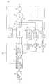
- FIG. 1is a diagram showing a structure of a controller in this embodiment.
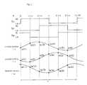
- FIG. 2shows waveforms of drive signals for the respective phases of a motor and of drive currents.
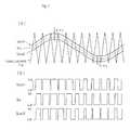
- FIG. 3is a drawing explaining correction of a drive signal according to this embodiment.
- a motor 20may be a multi-phase, for example, three-phase, AC motor, driven by a drive current supplied from a current supplier 12 , for example, an inverter, to each phase (U phase, V phase, W phase) of the motor 20 .
- the current supplier 12for example, an inverter, generates a drive current to be supplied to the motor 20 by converting a current from a power supply section 11 to a multi-phase AC based on drive signals for the respective phases (Su, Sv, Sw).
- the controller 10 in this embodimentgenerates a drive signal having a rectangular voltage waveform in which voltage levels are switched based on a rotation angle of the rotor which is detected by an angular sensor 21 , for example, a resolver, (hereinafter referred to as a detected angle).
- an angular sensor 21for example, a resolver, (hereinafter referred to as a detected angle).
- the controller 10 of a motorcomprises a power supply section 11 , an inverter 12 , a drive current detector 13 , an offset amount calculating section 14 , a correction amount calculator 15 , a voltage phase controller 16 , a drive signal generating section 17 , and a drive signal correcting section 18 .
- the voltage phase controller 16receives a torque command value • from an external controller, and determines a voltage phase • for each of the respective phases based on the received value. Based on the voltage phase • and a detected angle •, the drive signal generating section 17 , for example, a rectangular wave generator, generates drive signals for the respective phases (Suo, Svo, Swo), each having a rectangular voltage waveform. The drive signal correcting section 18 corrects these drive signals (Suo, Svo, Swo) into drive signals (Su, Sv, Sw). The correction will be described later.
- the drive current detectors 13detect values of drive currents for the respective phases (Iu, Iv, Iw) to be supplied from the current supplier 12 to the motor 20 . Based on the values of drive currents for the respective phases (Iu, Iv, Iw), which are detected by the drive current detectors 13 with the motor being driven, and the detected angle •, the offset amount calculating section 14 calculates offset amounts of the drive currents (Iu, Iv, Iw), for example by averaging the values of the drive currents (Iu, Iv, Iw) in one cycle.
- FIG. 2shows an example of calculation of an offset amount.
- FIG. 2shows, from the top of the figure, a detected angle •, drive signals for the respective phases (from top downward, drive current command values for U phase, V phase, W phase (Su, Sv, Sw)), and values of drive currents for the respective phases (Iu, Iv, Iw).
- values of drive currents for the respective phases (Iu, Iv, Iw)are sampled over a single rotation cycle T of a motor at timing determined by equally dividing a single rotation cycle T, and averaged so that the averaged value is determined as an offset value.
- Iuofs( Iu (1)+ Iu (2)+•••+ Iu ( n ))/ n
- Ivofs( Iv (1)+ Iv (2)+•••+ Iv ( n ))/ n
- Iwofs( Iw (1)+ Iw (2)+•••+ Iw ( n ))/ n are obtained, wherein n is the number of equidistant divisions of a single rotation cycle T.
- a drive signalis corrected by correcting its phase, as described below.
- the correction amount calculator 15calculates amounts to correct the drive signals for the respective phases as phase correction amounts (• • u, • • v, • • w).
- a proportional gain Ksp and an integral gain Ksiare determined in advance for each controller, and may be stored in advance in, for example, a memory, not shown.
- the drive signal correcting section 18corrects relevant drive signals (Suo, Svo, Swo). Specifically, in this embodiment, duty ratios of the drive signals (Suo, Svo, Swo), each having a rectangular waveform and output from the drive signal generating section 17 , are corrected by correcting their phases, as described above.
- FIG. 3shows one example of this correction.
- the dotted linerepresents a waveform of a U-phase drive signal Suo before correction, while the solid line represents that after correction.
- the duty ratiois corrected to have a larger value, as shown in FIG. 3( a ).
- the rectangular waveform of a drive signal Suois corrected by shifting the rising and falling of the waveform each by a correction amount • • u, which is calculated by the correction amount calculator 15 , such that the interval between these is widened.
- a larger duty ratioleads to a higher drive current, that is, a drive current shifted towards the positive side. As a result, the offset is corrected.
- the duty ratiois corrected to have a smaller value, as shown in FIG. 3( b ).
- the rectangular waveform of a drive signal Suois corrected by shifting the rising and falling of the waveform each by a correction amount • • u, which is calculated by the correction amount calculator 15 , such that the interval between these is narrowed.
- a smaller duty ratioleads to a lower drive current, that is, a drive current shifted toward the negative side. As a result, the offset is corrected.
- FIG. 4is a diagram showing a structure of a controller in this embodiment.
- FIG. 5is a diagram explaining correction of a drive signal in this embodiment.
- a motor 20is a multi-phase, for example, three-phase, AC motor, and driven by a drive current supplied from a current supplier 32 , for example, an inverter, to each phase (U phase, V phase, W phase) of a motor 20 .
- the current supplier 32for example, an inverter, generates a drive current to be supplied to the motor 20 by converting a current from a power supply section 31 to a multi-phase AC based on the drive signals for the respective phases (Su, Sv, Sw).
- the controller in this embodimentgenerates a drive signal having a PWM voltage waveform based on a rotation angle • of a rotor which is detected by an angular sensor 21 (a detected angle).
- the controller 30 of a motorcomprises a power supply section 31 , a current supplier 32 , a drive current detector 33 , an offset amount calculating section 34 , a correction amount calculator 35 , a voltage command value generating section 36 , a drive signal generating section 37 , and a drive signal correcting section 38 .
- the voltage command value generating section 36receives a torque command value • from an external controller, and accordingly generates voltage command values (Vuo, Vvo, Vwo), based on which drive signals (Su, Sv, Sw) are generated.
- the drive signal correcting section 38corrects the voltage command values (Vuo, Vvo, Vwo) and outputs voltage command values (Vu, Vv, Vw).
- the drive signal generating section 37for example, a PWM circuit, generates drive signals for the respective phases (Su, Sv, Sw) having PWM voltage waveforms based on the voltage command values (Vu, Vv, Vw) produced by the drive signal correcting section 38 . Correction into the voltage command values (Vu, Vv, Vw) and generation of the drive signals (Su, Sv, Sw) by a PWM circuit will be described later.
- the drive current detectors 33detect values of drive currents for the respective phases (Iu, Iv, Iw) to be supplied from the current supplier 32 to the motor 20 . Based on the values of drive currents for the respective phases (Iu, Iv, Iw), which are detected by the drive current detectors 33 with the motor being driven, the offset amount calculating section 34 calculates offset amounts of the drive currents (Iu, Iv, Iw).
- the current amount calculating section 34has, for example, a low-pass filter, and outputs offset amounts (Iuofs, Ivofs, Iwofs) of the respective drive currents (Iu, Iv, Iw). Employment of a low-pass filter having a lower filtering frequency enables output of an average. This arrangement enables easy calculation of offset amounts (Iuofs, Ivofs, Iwofs) without utilizing a phase of a detected angle •.
- the correction amount calculator 35calculates correction amounts for the voltage command values for respective phases (Vuo, Vvo, Vwo). Further, based on the calculated correction amounts, the drive signal correcting section 38 corrects the voltage command values (Vuo, Vvo, Vwo). In this embodiment, this correction is made by correcting the levels of the voltage command values (Vuo, Vvo, Vwo), based on which drive signals (Su, Sv, Sw) are generated.
- FIG. 5( a )shows voltage command values (Vu, Vuo 1 , Vuo 2 ) and a triangular wave TW in the drive signal generating section 37 , for example, a PWM circuit.
- FIG. 5( b )shows drive signals (Su, Suo 1 , Suo 2 ) which are generated based on these voltage command values (Vu, Vuo 1 , Vuo 2 ) and the triangular wave Tw.
- the drive signal generating section 37comprises a comparator to compare the voltage command values (Vu, Vv, Vw) and the triangular wave Tw so that drive signals (Su, Sv, Sw) are generated based on the comparison result.
- the drive signal generating section 37generates drive signals (Su, Sv, Sw) having a rectangular voltage waveform which is at a high voltage value Hi when the voltage command value (Vu, Vv, Vw) is larger than the triangular wave Tw and at a low voltage value Lo when the voltage command value (Vu, Vv, Vw) is smaller than the triangular wave Tw.
- drive signals Suo 1 , Suo 2are generated with respect to the voltage command values Vuo 1 , Vuo 2 , respectively.
- the correction amount calculator 35calculates correction amounts for the voltage command values for the respective phases based on the offset amounts calculated by the offset amount calculating section 34 . That is, where the correction to voltage command values is made by correcting voltage values of the voltage command values in this embodiment, as described above, the correction amount calculator 35 calculates voltage correction amounts (• Vu, • Vv, • Vw).
- the drive signal correcting section 38corrects the voltage command values (Vuo, Vvo, Vwo) into voltage command values (Vu, Vv, Vw) based on the correction amounts (• vu, • Vv, • Vw) calculated by the correction amount calculator 35 .
- the voltage command value Vuo 1is corrected to a voltage command value Vu, the level of which is lower than that of the value Vuo 1 by the offset amount• Vu.
Landscapes
- Engineering & Computer Science (AREA)
- Power Engineering (AREA)
- Control Of Motors That Do Not Use Commutators (AREA)
- Control Of Ac Motors In General (AREA)
- Inverter Devices (AREA)
Abstract
Description
Iuofs=(Iu(1)+Iu(2)+•••+Iu(n))/n
Ivofs=(Iv(1)+Iv(2)+•••+Iv(n))/n
Iwofs=(Iw(1)+Iw(2)+•••+Iw(n))/n
are obtained, wherein n is the number of equidistant divisions of a single rotation cycle T. In the example of
••u=Ksp•Iuofs+Ksi••Iuofs•

••v=Ksp•Ivofs+Ksi••Ivofs•
••w=Ksp•Iwofs+Ksi••Iwofs•
wherein Ksp is a proportional gain and Ksi is an integral gain. A proportional gain Ksp and an integral gain Ksi are determined in advance for each controller, and may be stored in advance in, for example, a memory, not shown.
•Vu=Kvp•Iuofs+Kvi ••Iuofs•
•vu=Kvp•Ivofs+Kvi ••Ivofs•
•Vw=Kvp•Iwofs+Kvi ••Iwofs•
wherein Kvp is a proportional gain and Kvi is an integral gain, A proportional gain Ksp and an integral gain Ksi are determined in advance for each controller, and may be stored in advance in, for example, a memory, not shown.
Claims (6)
Applications Claiming Priority (3)
| Application Number | Priority Date | Filing Date | Title |
|---|---|---|---|
| JP2000-116657 | 2000-04-18 | ||
| JP2000116657AJP4575547B2 (en) | 2000-04-18 | 2000-04-18 | Motor control device |
| PCT/JP2001/003326WO2001080416A1 (en) | 2000-04-18 | 2001-04-18 | Motor controller |
Publications (2)
| Publication Number | Publication Date |
|---|---|
| US20030102884A1 US20030102884A1 (en) | 2003-06-05 |
| US7772797B2true US7772797B2 (en) | 2010-08-10 |
Family
ID=18628093
Family Applications (1)
| Application Number | Title | Priority Date | Filing Date |
|---|---|---|---|
| US10/239,789Expired - Fee RelatedUS7772797B2 (en) | 2000-04-18 | 2001-04-18 | Motor controller |
Country Status (5)
| Country | Link |
|---|---|
| US (1) | US7772797B2 (en) |
| EP (1) | EP1283594B1 (en) |
| JP (1) | JP4575547B2 (en) |
| DE (1) | DE60140443D1 (en) |
| WO (1) | WO2001080416A1 (en) |
Cited By (4)
| Publication number | Priority date | Publication date | Assignee | Title |
|---|---|---|---|---|
| US20100237820A1 (en)* | 2009-03-23 | 2010-09-23 | Sinfonia Technology Co., Ltd. | Control system for motor |
| US20100281897A1 (en)* | 2007-11-16 | 2010-11-11 | Daikin Industries, Ltd. | Motor current calculation device and air conditioning apparatus |
| US20140253004A1 (en)* | 2013-03-05 | 2014-09-11 | Steering Solutions Ip Holding Corporation | Method and system to compensate for dynamic dc offset of measured phase current |
| US20140306452A1 (en)* | 2013-04-10 | 2014-10-16 | Hamilton Sunstrand Corportation | Interleaved motor controllers for an electric taxi system |
Families Citing this family (21)
| Publication number | Priority date | Publication date | Assignee | Title |
|---|---|---|---|---|
| JP2008167655A (en)* | 2001-08-27 | 2008-07-17 | Shinko Electric Co Ltd | Inverter testing device |
| JP4134716B2 (en)* | 2002-12-24 | 2008-08-20 | 日産自動車株式会社 | Electric motor current control device |
| WO2004062079A1 (en)* | 2002-12-26 | 2004-07-22 | Zexel Valeo Climate Control Corporation | Motor control device |
| JP4539192B2 (en)* | 2004-06-23 | 2010-09-08 | 日産自動車株式会社 | AC motor control device |
| JP4716680B2 (en)* | 2004-06-29 | 2011-07-06 | 東洋電機製造株式会社 | Control device for permanent magnet type synchronous motor |
| JP2006074951A (en)* | 2004-09-06 | 2006-03-16 | Nissan Motor Co Ltd | AC motor control device |
| JP4782525B2 (en)* | 2005-09-30 | 2011-09-28 | 日本電産サーボ株式会社 | Stepping motor drive device |
| JP4688172B2 (en)* | 2007-07-30 | 2011-05-25 | 本田技研工業株式会社 | Electric motor control device |
| JP4329855B2 (en)* | 2007-10-09 | 2009-09-09 | トヨタ自動車株式会社 | AC motor control device and AC motor control method |
| US8093914B2 (en)* | 2007-12-14 | 2012-01-10 | Cypress Semiconductor Corporation | Compensation circuit for a TX-RX capacitive sensor |
| JP5412772B2 (en)* | 2008-09-08 | 2014-02-12 | 株式会社デンソー | Rotating machine control device |
| JP5210822B2 (en)* | 2008-11-18 | 2013-06-12 | トヨタ自動車株式会社 | AC motor control device and electric vehicle equipped with the same |
| JP5866764B2 (en)* | 2011-02-04 | 2016-02-17 | ダイキン工業株式会社 | Power converter |
| JP5782769B2 (en)* | 2011-03-23 | 2015-09-24 | アイシン精機株式会社 | AC motor control method and control apparatus |
| DK2523009T3 (en)* | 2011-05-12 | 2015-04-07 | Abb Technology Ag | Method and device for monitoring the state afelektromekaniske systems |
| KR101284344B1 (en)* | 2011-12-09 | 2013-07-08 | 현대자동차주식회사 | Current sensor reconfigureation method of a vehicle having a motor |
| JP6019397B2 (en)* | 2012-09-07 | 2016-11-02 | パナソニックIpマネジメント株式会社 | Motor control device |
| WO2015177878A1 (en)* | 2014-05-20 | 2015-11-26 | 三菱電機株式会社 | Rotating machine control device and voltage error correction method |
| JP6398890B2 (en) | 2014-10-21 | 2018-10-03 | 株式会社デンソー | Control device for rotating electrical machine |
| US11147503B2 (en)* | 2015-09-30 | 2021-10-19 | The General Hospital Corporation | Systems and methods for an actively controlled optical imaging device |
| JP7154343B1 (en) | 2021-05-12 | 2022-10-17 | 三菱電機株式会社 | Rotating machine control device |
Citations (38)
| Publication number | Priority date | Publication date | Assignee | Title |
|---|---|---|---|---|
| US4611159A (en)* | 1982-11-25 | 1986-09-09 | Fanuc Ltd. | AC motor control system |
| JPS6321865A (en) | 1986-07-16 | 1988-01-29 | Nec Corp | Semiconductor device for transistor type dynamic memory cell |
| US4767976A (en)* | 1986-04-14 | 1988-08-30 | Hitachi, Ltd. | Control system for PWM inverter |
| JPS6430485U (en) | 1987-08-14 | 1989-02-23 | ||
| US4808903A (en)* | 1987-04-13 | 1989-02-28 | Hitachi, Ltd. | Vector control system for induction motors |
| JPH01270791A (en) | 1988-04-21 | 1989-10-30 | Mitsubishi Electric Corp | Speed controller for induction motor |
| EP0427527A2 (en) | 1989-11-07 | 1991-05-15 | Otis Elevator Company | Offset correction circuit of PWM inverter |
| JPH04134196U (en) | 1991-06-04 | 1992-12-14 | 西芝電機株式会社 | AC motor control device |
| JPH04134197U (en) | 1991-06-04 | 1992-12-14 | 西芝電機株式会社 | AC motor control device |
| JPH05328733A (en) | 1992-05-18 | 1993-12-10 | Hitachi Ltd | Air conditioner |
| JPH0643191A (en) | 1992-05-28 | 1994-02-18 | Matsushita Electric Ind Co Ltd | Offset automatic control device for current detector |
| US5298841A (en)* | 1990-04-18 | 1994-03-29 | Hitachi, Ltd. | Apparatus for controlling the speed of a moving object |
| JPH06121573A (en) | 1992-10-01 | 1994-04-28 | Matsushita Electric Ind Co Ltd | Automatic offset adjustment device for current detector |
| US5309075A (en)* | 1990-03-23 | 1994-05-03 | Toyoda Koki Kabushiki Kaisha | Digital servo-control apparatus for preventing torque variations |
| JPH06169574A (en) | 1992-11-30 | 1994-06-14 | Matsushita Electric Ind Co Ltd | Pwm inverter device |
| US5341286A (en)* | 1989-11-17 | 1994-08-23 | Matsushita Electric Industrial Co., Ltd. | Current detecting method |
| JPH07170799A (en) | 1993-12-10 | 1995-07-04 | Hitachi Ltd | AC motor control method and device, and motor current correction method |
| US5457375A (en)* | 1994-05-27 | 1995-10-10 | Emerson Electric Co. | Sensorless commutation controller for a poly-phase dynamoelectric machine |
| US5461329A (en)* | 1992-01-21 | 1995-10-24 | Martin Marietta Energy Systems, Inc. | Method and apparatus for generating motor current spectra to enhance motor system fault detection |
| JPH08119132A (en) | 1994-10-20 | 1996-05-14 | Koyo Seiko Co Ltd | Motor-operated power steering device |
| JPH08149882A (en) | 1994-11-24 | 1996-06-07 | Shibaura Eng Works Co Ltd | Motor control device |
| US5581452A (en)* | 1992-04-10 | 1996-12-03 | Kabushiki Kaisha Meidensha | Pulse width modulation inverter current detection method |
| US5780989A (en)* | 1994-08-04 | 1998-07-14 | Fanuc, Ltd. | Method and apparatus for AC servo motor control |
| US5798623A (en)* | 1996-02-12 | 1998-08-25 | Quantum Corporation | Switch mode sine wave driver for polyphase brushless permanent magnet motor |
| US5809438A (en)* | 1995-07-17 | 1998-09-15 | Honda Giken Kogyo Kabushiki Kaisha | Electric power steering apparatus |
| US5909366A (en)* | 1997-02-05 | 1999-06-01 | Mitsubishi Denki Kabushiki Kaisha | Controller for power transducers |
| US5936378A (en)* | 1997-03-27 | 1999-08-10 | Matsushita Electric Industrial Co., Ltd. | Motor controller |
| US5955860A (en)* | 1996-06-24 | 1999-09-21 | Toyota Jidosha Kabushiki Kaisha | Method of determining electrical angle and apparatus for the same |
| US6013994A (en)* | 1996-10-01 | 2000-01-11 | Nsk Ltd. | Controller of electric power-steering system |
| JP2000023488A (en) | 1998-07-06 | 2000-01-21 | Toyota Motor Corp | Motor drive current control device |
| JP2000078887A (en) | 1998-08-31 | 2000-03-14 | Mitsubishi Electric Corp | Motor control device |
| US6040673A (en)* | 1998-05-29 | 2000-03-21 | Matsushita Electric Industrial Co., Ltd. | Motor control apparatus |
| US6191966B1 (en)* | 1999-12-20 | 2001-02-20 | Texas Instruments Incorporated | Phase current sensor using inverter leg shunt resistor |
| US6225774B1 (en)* | 1997-06-10 | 2001-05-01 | Hitachi, Ltd. | Motor control method and motor control system |
| US6229719B1 (en)* | 1999-11-12 | 2001-05-08 | Hitachi, Ltd. | Method of inverter control and apparatus of the same |
| US6259226B1 (en)* | 1998-09-03 | 2001-07-10 | Mitsubishi Denki Kabushiki Kaisha | Controller for AC motor |
| US6281656B1 (en)* | 1998-09-30 | 2001-08-28 | Hitachi, Ltd. | Synchronous motor control device electric motor vehicle control device and method of controlling synchronous motor |
| US6388416B1 (en)* | 1999-08-05 | 2002-05-14 | Sharp Kabushiki Kaisha | Motor control device and motor control method |
Family Cites Families (8)
| Publication number | Priority date | Publication date | Assignee | Title |
|---|---|---|---|---|
| JPS6321865U (en)* | 1986-07-25 | 1988-02-13 | ||
| JPS6430485A (en)* | 1987-07-23 | 1989-02-01 | Mitsubishi Electric Corp | Elevator controller |
| JPH04134196A (en)* | 1990-09-27 | 1992-05-08 | Daikin Ind Ltd | Hermetic compressor |
| JPH04134197A (en)* | 1990-09-27 | 1992-05-08 | Zexel Corp | Solenoid valve control device for variable capacity type compressor |
| CN1190886C (en)* | 2000-02-28 | 2005-02-23 | 株式会社安川电机 | Pulse Width Modulation Pulse Control Method |
| JP3979561B2 (en)* | 2000-08-30 | 2007-09-19 | 株式会社日立製作所 | AC motor drive system |
| JP3867518B2 (en)* | 2001-06-06 | 2007-01-10 | 株式会社日立製作所 | Sensorless control system for synchronous motor |
| JP3888272B2 (en)* | 2002-09-25 | 2007-02-28 | 株式会社日立製作所 | AC motor control device and semiconductor device |
- 2000
- 2000-04-18JPJP2000116657Apatent/JP4575547B2/ennot_activeExpired - Lifetime
- 2001
- 2001-04-18USUS10/239,789patent/US7772797B2/ennot_activeExpired - Fee Related
- 2001-04-18DEDE60140443Tpatent/DE60140443D1/ennot_activeExpired - Lifetime
- 2001-04-18EPEP01921888Apatent/EP1283594B1/ennot_activeExpired - Lifetime
- 2001-04-18WOPCT/JP2001/003326patent/WO2001080416A1/enactiveApplication Filing
Patent Citations (39)
| Publication number | Priority date | Publication date | Assignee | Title |
|---|---|---|---|---|
| US4611159A (en)* | 1982-11-25 | 1986-09-09 | Fanuc Ltd. | AC motor control system |
| US4767976A (en)* | 1986-04-14 | 1988-08-30 | Hitachi, Ltd. | Control system for PWM inverter |
| JPS6321865A (en) | 1986-07-16 | 1988-01-29 | Nec Corp | Semiconductor device for transistor type dynamic memory cell |
| US4808903A (en)* | 1987-04-13 | 1989-02-28 | Hitachi, Ltd. | Vector control system for induction motors |
| JPS6430485U (en) | 1987-08-14 | 1989-02-23 | ||
| JPH01270791A (en) | 1988-04-21 | 1989-10-30 | Mitsubishi Electric Corp | Speed controller for induction motor |
| EP0427527A2 (en) | 1989-11-07 | 1991-05-15 | Otis Elevator Company | Offset correction circuit of PWM inverter |
| US5341286A (en)* | 1989-11-17 | 1994-08-23 | Matsushita Electric Industrial Co., Ltd. | Current detecting method |
| US5309075A (en)* | 1990-03-23 | 1994-05-03 | Toyoda Koki Kabushiki Kaisha | Digital servo-control apparatus for preventing torque variations |
| US5298841A (en)* | 1990-04-18 | 1994-03-29 | Hitachi, Ltd. | Apparatus for controlling the speed of a moving object |
| JPH04134196U (en) | 1991-06-04 | 1992-12-14 | 西芝電機株式会社 | AC motor control device |
| JPH04134197U (en) | 1991-06-04 | 1992-12-14 | 西芝電機株式会社 | AC motor control device |
| US5461329A (en)* | 1992-01-21 | 1995-10-24 | Martin Marietta Energy Systems, Inc. | Method and apparatus for generating motor current spectra to enhance motor system fault detection |
| US5581452A (en)* | 1992-04-10 | 1996-12-03 | Kabushiki Kaisha Meidensha | Pulse width modulation inverter current detection method |
| JPH05328733A (en) | 1992-05-18 | 1993-12-10 | Hitachi Ltd | Air conditioner |
| JPH0643191A (en) | 1992-05-28 | 1994-02-18 | Matsushita Electric Ind Co Ltd | Offset automatic control device for current detector |
| JPH06121573A (en) | 1992-10-01 | 1994-04-28 | Matsushita Electric Ind Co Ltd | Automatic offset adjustment device for current detector |
| JPH06169574A (en) | 1992-11-30 | 1994-06-14 | Matsushita Electric Ind Co Ltd | Pwm inverter device |
| JPH07170799A (en) | 1993-12-10 | 1995-07-04 | Hitachi Ltd | AC motor control method and device, and motor current correction method |
| US5457375A (en)* | 1994-05-27 | 1995-10-10 | Emerson Electric Co. | Sensorless commutation controller for a poly-phase dynamoelectric machine |
| US5780989A (en)* | 1994-08-04 | 1998-07-14 | Fanuc, Ltd. | Method and apparatus for AC servo motor control |
| JPH08119132A (en) | 1994-10-20 | 1996-05-14 | Koyo Seiko Co Ltd | Motor-operated power steering device |
| JPH08149882A (en) | 1994-11-24 | 1996-06-07 | Shibaura Eng Works Co Ltd | Motor control device |
| US5809438A (en)* | 1995-07-17 | 1998-09-15 | Honda Giken Kogyo Kabushiki Kaisha | Electric power steering apparatus |
| US5798623A (en)* | 1996-02-12 | 1998-08-25 | Quantum Corporation | Switch mode sine wave driver for polyphase brushless permanent magnet motor |
| US5955860A (en)* | 1996-06-24 | 1999-09-21 | Toyota Jidosha Kabushiki Kaisha | Method of determining electrical angle and apparatus for the same |
| US6013994A (en)* | 1996-10-01 | 2000-01-11 | Nsk Ltd. | Controller of electric power-steering system |
| US5909366A (en)* | 1997-02-05 | 1999-06-01 | Mitsubishi Denki Kabushiki Kaisha | Controller for power transducers |
| US5936378A (en)* | 1997-03-27 | 1999-08-10 | Matsushita Electric Industrial Co., Ltd. | Motor controller |
| US6225774B1 (en)* | 1997-06-10 | 2001-05-01 | Hitachi, Ltd. | Motor control method and motor control system |
| US6040673A (en)* | 1998-05-29 | 2000-03-21 | Matsushita Electric Industrial Co., Ltd. | Motor control apparatus |
| JP2000023488A (en) | 1998-07-06 | 2000-01-21 | Toyota Motor Corp | Motor drive current control device |
| JP2000078887A (en) | 1998-08-31 | 2000-03-14 | Mitsubishi Electric Corp | Motor control device |
| US6259226B1 (en)* | 1998-09-03 | 2001-07-10 | Mitsubishi Denki Kabushiki Kaisha | Controller for AC motor |
| US6281656B1 (en)* | 1998-09-30 | 2001-08-28 | Hitachi, Ltd. | Synchronous motor control device electric motor vehicle control device and method of controlling synchronous motor |
| US6456030B1 (en)* | 1998-09-30 | 2002-09-24 | Hitachi, Ltd. | Synchronous motor control device, electric motor vehicle control device and method of controlling synchronous motor |
| US6388416B1 (en)* | 1999-08-05 | 2002-05-14 | Sharp Kabushiki Kaisha | Motor control device and motor control method |
| US6229719B1 (en)* | 1999-11-12 | 2001-05-08 | Hitachi, Ltd. | Method of inverter control and apparatus of the same |
| US6191966B1 (en)* | 1999-12-20 | 2001-02-20 | Texas Instruments Incorporated | Phase current sensor using inverter leg shunt resistor |
Non-Patent Citations (1)
| Title |
|---|
| Supplemental European Search Report, Appln. No. 01921888.2-2207, dated Jul. 18, 2007. |
Cited By (7)
| Publication number | Priority date | Publication date | Assignee | Title |
|---|---|---|---|---|
| US20100281897A1 (en)* | 2007-11-16 | 2010-11-11 | Daikin Industries, Ltd. | Motor current calculation device and air conditioning apparatus |
| US20100237820A1 (en)* | 2009-03-23 | 2010-09-23 | Sinfonia Technology Co., Ltd. | Control system for motor |
| US8228018B2 (en)* | 2009-03-23 | 2012-07-24 | Sinfonia Technology Co., Ltd. | Control system for motor |
| US20140253004A1 (en)* | 2013-03-05 | 2014-09-11 | Steering Solutions Ip Holding Corporation | Method and system to compensate for dynamic dc offset of measured phase current |
| US9172318B2 (en)* | 2013-03-05 | 2015-10-27 | Steering Solutions Ip Holding Corporation | Method and system to compensate for dynamic DC offset of measured phase current |
| US20140306452A1 (en)* | 2013-04-10 | 2014-10-16 | Hamilton Sunstrand Corportation | Interleaved motor controllers for an electric taxi system |
| US8866326B1 (en)* | 2013-04-10 | 2014-10-21 | Hamilton Sundstrand Corporation | Interleaved motor controllers for an electric taxi system |
Also Published As
| Publication number | Publication date |
|---|---|
| EP1283594A4 (en) | 2007-08-15 |
| EP1283594B1 (en) | 2009-11-11 |
| JP2001298992A (en) | 2001-10-26 |
| JP4575547B2 (en) | 2010-11-04 |
| WO2001080416A1 (en) | 2001-10-25 |
| DE60140443D1 (en) | 2009-12-24 |
| US20030102884A1 (en) | 2003-06-05 |
| EP1283594A1 (en) | 2003-02-12 |
Similar Documents
| Publication | Publication Date | Title |
|---|---|---|
| US7772797B2 (en) | Motor controller | |
| JP4985395B2 (en) | Current control device and current offset correction method thereof | |
| US8674652B2 (en) | Motor control device | |
| KR100789441B1 (en) | Current detection device and method of the inverter | |
| EP2066021B1 (en) | Controller of multi-phase electric motor | |
| US6873126B2 (en) | Motor drive method and motor driver | |
| US8115436B2 (en) | Motor control apparatus and motor system | |
| US7365506B2 (en) | Motor driving device, motor driving method, and motor apparatus | |
| US20220166362A1 (en) | Motor controller, motor system and method for controlling motor | |
| WO2020059815A1 (en) | Motor control device, motor system, and inverter control method | |
| US20230111291A1 (en) | Motor controller, motor system and method for controlling motor | |
| JP5104083B2 (en) | Power conversion device and power conversion method | |
| JP4171612B2 (en) | Inverter device, semiconductor integrated circuit device | |
| WO2020059814A1 (en) | Motor control device, motor system and inverter control method | |
| JP2006034086A (en) | Motor driving device, motor driving method and electronic device | |
| JP2006074951A (en) | AC motor control device | |
| JP4677668B2 (en) | Multiphase AC motor drive controller | |
| JPH0947065A (en) | Motor drive controller | |
| JP2019154143A (en) | Motor drive device | |
| JP3788346B2 (en) | Voltage type PWM inverter control device | |
| US20220166363A1 (en) | Motor controller, motor system and method for controlling motor | |
| JP2004336895A (en) | Drive device for brushless motor | |
| US20250300587A1 (en) | Rotating machine control device | |
| JP3552380B2 (en) | Brushless motor drive | |
| CN113039717A (en) | AC rotating machine control device |
Legal Events
| Date | Code | Title | Description |
|---|---|---|---|
| AS | Assignment | Owner name:TOYOTA JIDOSHA KABUSHIKI KAISHA, JAPAN Free format text:ASSIGNMENT OF ASSIGNORS INTEREST;ASSIGNORS:SATO, EIJI;OHTANI, HIROKI;REEL/FRAME:013730/0137;SIGNING DATES FROM 20020820 TO 20020826 Owner name:KABUSHIKI KAISHA TOYOTA CHUO KENKYUSHO, JAPAN Free format text:ASSIGNMENT OF ASSIGNORS INTEREST;ASSIGNORS:SATO, EIJI;OHTANI, HIROKI;REEL/FRAME:013730/0137;SIGNING DATES FROM 20020820 TO 20020826 Owner name:TOYOTA JIDOSHA KABUSHIKI KAISHA, JAPAN Free format text:ASSIGNMENT OF ASSIGNORS INTEREST;ASSIGNORS:SATO, EIJI;OHTANI, HIROKI;SIGNING DATES FROM 20020820 TO 20020826;REEL/FRAME:013730/0137 Owner name:KABUSHIKI KAISHA TOYOTA CHUO KENKYUSHO, JAPAN Free format text:ASSIGNMENT OF ASSIGNORS INTEREST;ASSIGNORS:SATO, EIJI;OHTANI, HIROKI;SIGNING DATES FROM 20020820 TO 20020826;REEL/FRAME:013730/0137 | |
| STCF | Information on status: patent grant | Free format text:PATENTED CASE | |
| CC | Certificate of correction | ||
| FEPP | Fee payment procedure | Free format text:PAYOR NUMBER ASSIGNED (ORIGINAL EVENT CODE: ASPN); ENTITY STATUS OF PATENT OWNER: LARGE ENTITY | |
| FPAY | Fee payment | Year of fee payment:4 | |
| MAFP | Maintenance fee payment | Free format text:PAYMENT OF MAINTENANCE FEE, 8TH YEAR, LARGE ENTITY (ORIGINAL EVENT CODE: M1552) Year of fee payment:8 | |
| FEPP | Fee payment procedure | Free format text:MAINTENANCE FEE REMINDER MAILED (ORIGINAL EVENT CODE: REM.); ENTITY STATUS OF PATENT OWNER: LARGE ENTITY | |
| LAPS | Lapse for failure to pay maintenance fees | Free format text:PATENT EXPIRED FOR FAILURE TO PAY MAINTENANCE FEES (ORIGINAL EVENT CODE: EXP.); ENTITY STATUS OF PATENT OWNER: LARGE ENTITY | |
| STCH | Information on status: patent discontinuation | Free format text:PATENT EXPIRED DUE TO NONPAYMENT OF MAINTENANCE FEES UNDER 37 CFR 1.362 | |
| FP | Lapsed due to failure to pay maintenance fee | Effective date:20220810 |