US7771654B1 - Apparatus for monitoring gaseous components of a flue gas - Google Patents
Apparatus for monitoring gaseous components of a flue gasDownload PDFInfo
- Publication number
- US7771654B1 US7771654B1US11/517,497US51749706AUS7771654B1US 7771654 B1US7771654 B1US 7771654B1US 51749706 AUS51749706 AUS 51749706AUS 7771654 B1US7771654 B1US 7771654B1
- Authority
- US
- United States
- Prior art keywords
- flue gas
- concentration
- enclosure
- monitoring system
- sample
- Prior art date
- Legal status (The legal status is an assumption and is not a legal conclusion. Google has not performed a legal analysis and makes no representation as to the accuracy of the status listed.)
- Active, expires
Links
- 239000003546flue gasSubstances0.000titleclaimsabstractdescription87
- UGFAIRIUMAVXCW-UHFFFAOYSA-NCarbon monoxideChemical compound[O+]#[C-]UGFAIRIUMAVXCW-UHFFFAOYSA-N0.000titleclaimsabstractdescription85
- 238000012544monitoring processMethods0.000titleclaimsabstractdescription38
- QGZKDVFQNNGYKY-UHFFFAOYSA-NAmmoniaChemical compoundNQGZKDVFQNNGYKY-UHFFFAOYSA-N0.000claimsabstractdescription95
- 229910021529ammoniaInorganic materials0.000claimsabstractdescription35
- 239000007789gasSubstances0.000claimsdescription84
- 229910000069nitrogen hydrideInorganic materials0.000claimsdescription24
- 230000004044responseEffects0.000claimsdescription18
- 239000000463materialSubstances0.000claimsdescription7
- 238000002156mixingMethods0.000claimsdescription7
- 238000005201scrubbingMethods0.000claimsdescription7
- 239000007787solidSubstances0.000claimsdescription7
- 238000001816coolingMethods0.000claimsdescription6
- 239000011521glassSubstances0.000claimsdescription3
- BPQQTUXANYXVAA-UHFFFAOYSA-NOrthosilicateChemical compound[O-][Si]([O-])([O-])[O-]BPQQTUXANYXVAA-UHFFFAOYSA-N0.000claimsdescription2
- 239000010935stainless steelSubstances0.000claimsdescription2
- 229910001220stainless steelInorganic materials0.000claimsdescription2
- 239000000654additiveSubstances0.000claims3
- 230000000996additive effectEffects0.000claims3
- 238000000926separation methodMethods0.000claims3
- 239000000523sampleSubstances0.000description91
- MWUXSHHQAYIFBG-UHFFFAOYSA-Nnitrogen oxideInorganic materialsO=[N]MWUXSHHQAYIFBG-UHFFFAOYSA-N0.000description18
- 239000003570airSubstances0.000description12
- 238000004458analytical methodMethods0.000description8
- XLYOFNOQVPJJNP-UHFFFAOYSA-NwaterChemical compoundOXLYOFNOQVPJJNP-UHFFFAOYSA-N0.000description8
- IJGRMHOSHXDMSA-UHFFFAOYSA-NAtomic nitrogenChemical compoundN#NIJGRMHOSHXDMSA-UHFFFAOYSA-N0.000description7
- HEMHJVSKTPXQMS-UHFFFAOYSA-MSodium hydroxideChemical compound[OH-].[Na+]HEMHJVSKTPXQMS-UHFFFAOYSA-M0.000description6
- 238000004868gas analysisMethods0.000description6
- 238000000034methodMethods0.000description6
- 230000003750conditioning effectEffects0.000description5
- 239000007788liquidSubstances0.000description4
- 238000005070samplingMethods0.000description4
- 238000010586diagramMethods0.000description3
- 230000006870functionEffects0.000description3
- CURLTUGMZLYLDI-UHFFFAOYSA-NCarbon dioxideChemical compoundO=C=OCURLTUGMZLYLDI-UHFFFAOYSA-N0.000description2
- PXHVJJICTQNCMI-UHFFFAOYSA-NNickelChemical compound[Ni]PXHVJJICTQNCMI-UHFFFAOYSA-N0.000description2
- 239000003513alkaliSubstances0.000description2
- 229910045601alloyInorganic materials0.000description2
- 239000000956alloySubstances0.000description2
- 230000005540biological transmissionEffects0.000description2
- 238000000576coating methodMethods0.000description2
- 238000009833condensationMethods0.000description2
- 230000005494condensationEffects0.000description2
- 239000000470constituentSubstances0.000description2
- 239000000356contaminantSubstances0.000description2
- 238000001514detection methodMethods0.000description2
- 238000010790dilutionMethods0.000description2
- 239000012895dilutionSubstances0.000description2
- 239000003792electrolyteSubstances0.000description2
- 238000009434installationMethods0.000description2
- 238000012423maintenanceMethods0.000description2
- 230000007257malfunctionEffects0.000description2
- 229910052757nitrogenInorganic materials0.000description2
- JTJMJGYZQZDUJJ-UHFFFAOYSA-NphencyclidineChemical classC1CCCCN1C1(C=2C=CC=CC=2)CCCCC1JTJMJGYZQZDUJJ-UHFFFAOYSA-N0.000description2
- 238000011144upstream manufacturingMethods0.000description2
- 239000012808vapor phaseSubstances0.000description2
- VYZAMTAEIAYCRO-UHFFFAOYSA-NChromiumChemical compound[Cr]VYZAMTAEIAYCRO-UHFFFAOYSA-N0.000description1
- ZOKXTWBITQBERF-UHFFFAOYSA-NMolybdenumChemical compound[Mo]ZOKXTWBITQBERF-UHFFFAOYSA-N0.000description1
- PMZURENOXWZQFD-UHFFFAOYSA-LSodium SulfateChemical compound[Na+].[Na+].[O-]S([O-])(=O)=OPMZURENOXWZQFD-UHFFFAOYSA-L0.000description1
- 239000002253acidSubstances0.000description1
- 238000003915air pollutionMethods0.000description1
- 239000012080ambient airSubstances0.000description1
- 238000013459approachMethods0.000description1
- 239000007864aqueous solutionSubstances0.000description1
- 239000002585baseSubstances0.000description1
- 230000015572biosynthetic processEffects0.000description1
- 229910002092carbon dioxideInorganic materials0.000description1
- 239000001569carbon dioxideSubstances0.000description1
- 229910002091carbon monoxideInorganic materials0.000description1
- 238000006243chemical reactionMethods0.000description1
- 229910052804chromiumInorganic materials0.000description1
- 239000011651chromiumSubstances0.000description1
- 239000011248coating agentSubstances0.000description1
- 238000002485combustion reactionMethods0.000description1
- 150000001875compoundsChemical class0.000description1
- 238000011109contaminationMethods0.000description1
- 238000005260corrosionMethods0.000description1
- 230000007797corrosionEffects0.000description1
- 230000001627detrimental effectEffects0.000description1
- 239000012470diluted sampleSubstances0.000description1
- 238000005367electrostatic precipitationMethods0.000description1
- 238000005516engineering processMethods0.000description1
- 239000003344environmental pollutantSubstances0.000description1
- 238000001914filtrationMethods0.000description1
- 239000000446fuelSubstances0.000description1
- 229910000856hastalloyInorganic materials0.000description1
- 238000010438heat treatmentMethods0.000description1
- 238000011065in-situ storageMethods0.000description1
- 238000005259measurementMethods0.000description1
- 229910052751metalInorganic materials0.000description1
- 239000002184metalSubstances0.000description1
- 150000007522mineralic acidsChemical class0.000description1
- 239000000203mixtureSubstances0.000description1
- 229910052750molybdenumInorganic materials0.000description1
- 239000011733molybdenumSubstances0.000description1
- 229910052759nickelInorganic materials0.000description1
- 229910000510noble metalInorganic materials0.000description1
- 239000013618particulate matterSubstances0.000description1
- 231100000719pollutantToxicity0.000description1
- 238000012545processingMethods0.000description1
- 230000035945sensitivityEffects0.000description1
- 229910052938sodium sulfateInorganic materials0.000description1
- 235000011152sodium sulphateNutrition0.000description1
- 239000000126substanceSubstances0.000description1
- XTQHKBHJIVJGKJ-UHFFFAOYSA-Nsulfur monoxideChemical classS=OXTQHKBHJIVJGKJ-UHFFFAOYSA-N0.000description1
- 229910052815sulfur oxideInorganic materials0.000description1
- 210000003954umbilical cordAnatomy0.000description1
- 230000000007visual effectEffects0.000description1
Images


Classifications
- G—PHYSICS
- G01—MEASURING; TESTING
- G01N—INVESTIGATING OR ANALYSING MATERIALS BY DETERMINING THEIR CHEMICAL OR PHYSICAL PROPERTIES
- G01N33/00—Investigating or analysing materials by specific methods not covered by groups G01N1/00 - G01N31/00
- G01N33/0004—Gaseous mixtures, e.g. polluted air
- G01N33/0009—General constructional details of gas analysers, e.g. portable test equipment
- G01N33/0027—General constructional details of gas analysers, e.g. portable test equipment concerning the detector
- G01N33/0031—General constructional details of gas analysers, e.g. portable test equipment concerning the detector comprising two or more sensors, e.g. a sensor array
- G—PHYSICS
- G01—MEASURING; TESTING
- G01N—INVESTIGATING OR ANALYSING MATERIALS BY DETERMINING THEIR CHEMICAL OR PHYSICAL PROPERTIES
- G01N33/00—Investigating or analysing materials by specific methods not covered by groups G01N1/00 - G01N31/00
- G01N33/0004—Gaseous mixtures, e.g. polluted air
- G01N33/0009—General constructional details of gas analysers, e.g. portable test equipment
- G01N33/0027—General constructional details of gas analysers, e.g. portable test equipment concerning the detector
- G01N33/0036—General constructional details of gas analysers, e.g. portable test equipment concerning the detector specially adapted to detect a particular component
- G01N33/0037—NOx
- G—PHYSICS
- G01—MEASURING; TESTING
- G01N—INVESTIGATING OR ANALYSING MATERIALS BY DETERMINING THEIR CHEMICAL OR PHYSICAL PROPERTIES
- G01N33/00—Investigating or analysing materials by specific methods not covered by groups G01N1/00 - G01N31/00
- G01N33/0004—Gaseous mixtures, e.g. polluted air
- G01N33/0009—General constructional details of gas analysers, e.g. portable test equipment
- G01N33/0027—General constructional details of gas analysers, e.g. portable test equipment concerning the detector
- G01N33/0036—General constructional details of gas analysers, e.g. portable test equipment concerning the detector specially adapted to detect a particular component
- G01N33/0042—SO2 or SO3
- G—PHYSICS
- G01—MEASURING; TESTING
- G01N—INVESTIGATING OR ANALYSING MATERIALS BY DETERMINING THEIR CHEMICAL OR PHYSICAL PROPERTIES
- G01N33/00—Investigating or analysing materials by specific methods not covered by groups G01N1/00 - G01N31/00
- G01N33/0004—Gaseous mixtures, e.g. polluted air
- G01N33/0009—General constructional details of gas analysers, e.g. portable test equipment
- G01N33/0027—General constructional details of gas analysers, e.g. portable test equipment concerning the detector
- G01N33/0036—General constructional details of gas analysers, e.g. portable test equipment concerning the detector specially adapted to detect a particular component
- G01N33/0054—Ammonia
- Y—GENERAL TAGGING OF NEW TECHNOLOGICAL DEVELOPMENTS; GENERAL TAGGING OF CROSS-SECTIONAL TECHNOLOGIES SPANNING OVER SEVERAL SECTIONS OF THE IPC; TECHNICAL SUBJECTS COVERED BY FORMER USPC CROSS-REFERENCE ART COLLECTIONS [XRACs] AND DIGESTS
- Y02—TECHNOLOGIES OR APPLICATIONS FOR MITIGATION OR ADAPTATION AGAINST CLIMATE CHANGE
- Y02A—TECHNOLOGIES FOR ADAPTATION TO CLIMATE CHANGE
- Y02A50/00—TECHNOLOGIES FOR ADAPTATION TO CLIMATE CHANGE in human health protection, e.g. against extreme weather
- Y02A50/20—Air quality improvement or preservation, e.g. vehicle emission control or emission reduction by using catalytic converters
- Y—GENERAL TAGGING OF NEW TECHNOLOGICAL DEVELOPMENTS; GENERAL TAGGING OF CROSS-SECTIONAL TECHNOLOGIES SPANNING OVER SEVERAL SECTIONS OF THE IPC; TECHNICAL SUBJECTS COVERED BY FORMER USPC CROSS-REFERENCE ART COLLECTIONS [XRACs] AND DIGESTS
- Y10—TECHNICAL SUBJECTS COVERED BY FORMER USPC
- Y10T—TECHNICAL SUBJECTS COVERED BY FORMER US CLASSIFICATION
- Y10T436/00—Chemistry: analytical and immunological testing
- Y10T436/17—Nitrogen containing
- Y10T436/173845—Amine and quaternary ammonium
- Y10T436/175383—Ammonia
- Y—GENERAL TAGGING OF NEW TECHNOLOGICAL DEVELOPMENTS; GENERAL TAGGING OF CROSS-SECTIONAL TECHNOLOGIES SPANNING OVER SEVERAL SECTIONS OF THE IPC; TECHNICAL SUBJECTS COVERED BY FORMER USPC CROSS-REFERENCE ART COLLECTIONS [XRACs] AND DIGESTS
- Y10—TECHNICAL SUBJECTS COVERED BY FORMER USPC
- Y10T—TECHNICAL SUBJECTS COVERED BY FORMER US CLASSIFICATION
- Y10T436/00—Chemistry: analytical and immunological testing
- Y10T436/17—Nitrogen containing
- Y10T436/177692—Oxides of nitrogen
- Y10T436/178459—Only nitrogen dioxide
- Y—GENERAL TAGGING OF NEW TECHNOLOGICAL DEVELOPMENTS; GENERAL TAGGING OF CROSS-SECTIONAL TECHNOLOGIES SPANNING OVER SEVERAL SECTIONS OF THE IPC; TECHNICAL SUBJECTS COVERED BY FORMER USPC CROSS-REFERENCE ART COLLECTIONS [XRACs] AND DIGESTS
- Y10—TECHNICAL SUBJECTS COVERED BY FORMER USPC
- Y10T—TECHNICAL SUBJECTS COVERED BY FORMER US CLASSIFICATION
- Y10T436/00—Chemistry: analytical and immunological testing
- Y10T436/17—Nitrogen containing
- Y10T436/177692—Oxides of nitrogen
- Y10T436/179228—Both nitrogen oxide and dioxide
- Y—GENERAL TAGGING OF NEW TECHNOLOGICAL DEVELOPMENTS; GENERAL TAGGING OF CROSS-SECTIONAL TECHNOLOGIES SPANNING OVER SEVERAL SECTIONS OF THE IPC; TECHNICAL SUBJECTS COVERED BY FORMER USPC CROSS-REFERENCE ART COLLECTIONS [XRACs] AND DIGESTS
- Y10—TECHNICAL SUBJECTS COVERED BY FORMER USPC
- Y10T—TECHNICAL SUBJECTS COVERED BY FORMER US CLASSIFICATION
- Y10T436/00—Chemistry: analytical and immunological testing
- Y10T436/18—Sulfur containing
- Y10T436/186—Sulfur dioxide
- Y—GENERAL TAGGING OF NEW TECHNOLOGICAL DEVELOPMENTS; GENERAL TAGGING OF CROSS-SECTIONAL TECHNOLOGIES SPANNING OVER SEVERAL SECTIONS OF THE IPC; TECHNICAL SUBJECTS COVERED BY FORMER USPC CROSS-REFERENCE ART COLLECTIONS [XRACs] AND DIGESTS
- Y10—TECHNICAL SUBJECTS COVERED BY FORMER USPC
- Y10T—TECHNICAL SUBJECTS COVERED BY FORMER US CLASSIFICATION
- Y10T436/00—Chemistry: analytical and immunological testing
- Y10T436/25—Chemistry: analytical and immunological testing including sample preparation
- Y10T436/25875—Gaseous sample or with change of physical state
Definitions
- This inventionrelates to an apparatus for monitoring ammonia in gaseous streams, particularly in flue gas streams.
- the apparatusis transportable but can be permanently installed.
- the flue gascan be monitored in real time.
- stack sample probeshave been connected to gas analysis equipment through long sample lines.
- a pump near the gas analysis equipmentcreates suction in the long sample line that pulls gas into the sample probe and down the sample line to the pump whose outlet discharges sample gas into the gas analysis equipment.
- Continuous monitoring systems with such long sample transport linesare plagued by a number of gas monitoring inaccuracies. For example, when a heated gas sample taken from a flue gas stack is carried the length of a long sample transport line, the potential exists for the sample to cool and certain vapor phase constituents in the sample to condense in the sample transport line. This condensed liquid gathers on the walls of the transport line and collects at low points along the transport line.
- some conventional systemsinsulate and heat the sample transport line to prevent condensation between the sampling location and the analysis location.
- gas transport line heatersare typically unreliable and have a tendency to malfunction. After such a malfunction is discovered, it is necessary to turn off the monitoring system and clean condensate out of the gas transport line. Such maintenance is both expensive and time consuming.
- an apparatus for measuring the concentration of ammonia in a gaseous samplewhich apparatus comprises:
- an enclosurehaving a plurality of enclosing panels, wherein one panel is a top panel and one panel is a bottom panel and the remaining panels are side panels;
- an NO sensorfor generating an electrical output in response to the concentration of NO in a gaseous sample
- an NO 2 sensorfor generating an electrical output in response to the concentration of NO 2 in said gaseous sample
- an SO 2 sensorfor generating an electrical output in response to the concentration of SO 2 in said gaseous sample
- a flow meterfor metering the flow of gas sample to the indicating means.
- FIG. 1is a schematic diagram of a preferred embodiment of the ammonia analyzer of the present invention.
- FIG. 2is a diagram of a preferred embodiment of a pre-conditioning apparatus for a sample gas introduced into the ammonia analyzer of the present invention.
- FIG. 3is a simplified representation of the cover of the ammonia analyzer of the present invention showing some preferred elements.
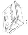
- FIG. 4is a perspective view of an ammonia analyzer box of the present invention showing the cover of FIG. 3 hereof and few preferred features.
- flue gasas used herein is as it is generally known in the art. It is typically a gas that exits to the atmosphere via a flue, or stack, which is a pipe or channel for conveying exhaust gases from a source such as a fireplace, furnace, boiler or generator.
- flue gasand “stack gas” are used interchangeably herein.
- a preferred source of flue gas, to be treated in accordance with the present invention,is from power plants, including coal-fired plants.
- the composition of the flue gaswill depend on what is burned, but it will typically be comprised of predominantly carbon dioxide, water vapor, heated air and minor amounts of pollutants, such as particulate matter, carbon monoxide, nitrogen oxides, sulfur oxides, and ammonia.
- Ammoniais sometimes injected into the flue gas stream of deNOx processes to convert nitrogen oxides to nitrogen and water. That is, it is sometimes necessary to reduce the concentrations of the nitrogen oxide gases (NO, NO 2 ) in the flue gas stream by use of a reactive gas, such as ammonia.
- a reactive gassuch as ammonia.
- the ammoniais typically added to the flue gas stream at or near the base of the stack so as to react with the nitrogen oxide constituents of the stack gas and thereby form by chemical reaction, molecular nitrogen and water vapor, such transformed compounds being environmentally significantly more benign than the nitrogen oxides and the injected ammonia gas.
- FIG. 1 hereofis a simplified diagram of a preferred embodiment of an ammonia analyzer 1 of the present invention.
- the components of the analyzerare contained in an enclosure, or box, having enclosing walls or panels.
- the enclosurecan be of any suitable geometric shape, it is preferred that it be rectangular or square in shape, as represented by FIG. 4 hereof.
- a sample of flue gasis obtained directly from a so-called “stack” by use of a suitable flue gas sampling probe.
- a suitable flue gas sampling probeSuch probes are well known in the art and may be fabricated from any material compatible with the stack, or flue gas. Typically, these probes are manufactured from high-strength, nickel based, corrosion resistant alloys that may contain other metal components, such as molybdenum and chromium. Such alloys are generally available under the Hastelloy tradename. It is within the scope of this invention that the probe has an inner glass lining.
- the sample of flue gascan either be sent directly to the analyzer via line 50 or can first be preconditioned by removing particulates and mixing with a suitable amount of air, preferably substantially moisture and contaminate free air.
- a suitable amount of airpreferably substantially moisture and contaminate free air.
- the ratio of air to flue gaswill vary depending on the moisture content of the flue gas and the precise ratio needed can easily be determined by one having ordinary skill in the art.
- the flue gas sampleneed not be completely dry, it is necessary that the temperature of the flue gas at the electrochemical sensors be above the dew point.
- Psychrometric chartsare readily available and are used to determine the quantity of air that must be added to the flue gas sample to insure that the sample remains in the vapor phase through the sensor area. The dilution rate should be minimized because the detection limit is directly and proportionally impacted thereby.
- the sample of flue gasbe preconditioned such as in a way that is illustrated in FIG. 2 hereof.
- a sample of flue gasis obtained from the stack via a suitable probe and passed via line 10 to a first separator S 1 for removing at least a portion of the particulates that may be present, particularly the larger size particulates.
- Separator S 1can be any suitable device for separating solids from a gas. Non-limiting examples of such devices include electrostatic precipitation devices and cyclones. Cyclones are preferred.
- the resulting effluent sample flue gas from separator S 1is optionally, but preferably, passed via line 20 to second separator S 2 wherein at least a portion of any remaining particulates, particularly the smaller size particulates are removed, preferably by use of a conventional filtering device such as wire mesh, wedge-wire or sintered stainless steel filter.
- the resulting substantially solids-free effluent sample flue gas stream from separator S 2is passed via line 30 and valve V 1 to mixing zone MZ where it is mixed with a predetermined amount of air, preferably substantially moisture-free air from an air source AS via line 40 and valve V 2 .
- the quantity of dilution airvaries depending on the temperature and initial moisture content of the sampled gas stream.
- the sample of flue gasis passed into analyzer box 1 via line 50 through inlet port IP where it is moved, preferably by use of a suitable pump P, preferably a conventional diaphragm pump of suitable size, and through a gas flow metering device FM of suitable size for the flows required for the electrochemical sensors used herein, typically 1 to 4 liters per minute. It is preferred that the pressure of the sample gas within analyzer 1 be controlled by use of a suitable pressure gas PG before passing the flue gas sample through the electrochemical sensors for analysis.
- the sample gasis passed to NO sensor I 1 that is capable of sensing and measuring the concentration of NO in the sample.
- Electrochemical sensorsare essentially fuel cells composed of noble metal electrodes in a suitable electrolyte.
- the electrolyteis typically an aqueous solution of a strong inorganic acid.
- the cellWhen the target gas is detected, the cell generates a small electrical current proportional to the concentration of the target gas in the flue gas sample.
- Electrochemical sensors suitable for use hereinare readily available form such vendors as City Technologies of Great Britain, Delphian Corporation of Northvale, N.J.
- the electrochemical sensorsare chosen for the particular target gas(es) and concentration of target gas(es) to be measured.
- the sensoris preferably chosen with a sensitivity of 0 to 100 wppm NO, which will be suitable for most flue gas streams.
- PLCprogrammable logic controller
- CPUcentral processing unit
- the PLC, or equivalent controllerwill also control other parameters integral to the measurement of the sample including, but not limited to the heating and cooling devices for the sample conditioning system and umbilical cords and boxes.
- the output from the PLC corresponding to the input from sensor I 1is sent to displaying means D 1 that is capable of displaying the concentration of NO in the flue gas sample in a predetermined form.
- the lines in this Figure representing the outputs of each sensor as well as each output of the PLCcan be either a hardwire installation as well as a wireless installation and that these lines merely represent the transmission of electrical signals.
- all display means of this inventionwill be chosen to display the concentration of the target gas in any suitable predetermined form.
- the concentrationcan be displayed in analog form via an analog gauge, or it can be displayed as a digital read-out, or it can be displayed by use of a light that is either on or off when the concentration of the target gas is in a given predetermined range or exceeds a predetermined value. It is preferred that the display means display the concentration by way of a light that will be on or off, more preferably on, when the concentration of NO is in a predetermined range. That is, if the concentration of NO is within the 0 to 100 wppm range, then D 1 will be on.
- each target gascan easily be estimated by those having ordinary skill in the art for each source (flue gas) prior to analysis with the apparatus of the present invention so that the appropriate sensor (electrochemical cells) can be chosen.
- Electrochemical cellstypically have the flexibility to be calibrated for several ranges by setting one or more dip switches or by using an electronic means to modify the cell's performance. It is within the scope of this invention that one or more of the electrochemical cells used in the instant invention be obtained with the predesigned range needed for the particular target gas and concentration of target gas. That is, based on a preliminary estimate, the appropriate cell can be selected and installed for each situation.
- the target gas sampleafter passing through NO sensor I 1 , is conducted to NO 2 sensor I 2 where the concentration of NO 2 is detected and measured. It is also preferred that I 2 be a suitable electrochemical sensor and that it measure the concentration of NO 2 in the range of 0 to 50 wppm, preferably in the range of 0 to 20 wppm.
- An electrical output proportional to the concentration of NO 2is sent to PLC which in turn sends a suitable output signal to display D 2 which will display the concentration of NO 2 in the sample.
- the flue gas samplewill be conducted from NO 2 sensor I 2 via line 70 , and by-pass line BP if desired, and line 80 to SO 2 sensor I 3 .
- An electrical outputis produced by SO 2 sensor I 3 that is proportional to the concentration of SO 2 in the sample and sent to the PLC then to display means D 3 which is capable of receiving the output signal from PLC and displaying the concentration of SO 2 .
- the concentrationbe displayed in the form of a light to indicate that the concentration is within or outside of a predetermined concentration range.
- valve V 3can be actuated to a position that will allow the sample gas to be passed through SO 2 scrubber S, without passing through by-pass line BP.
- Valve V 3can also be controlled by the PLC based on the information it receives from SO 2 sensor I 3 .
- Scrubber Swill remove substantially all of any SO 2 in the sample gas before the sample gas is conducted to the ammonia detecting electrochemical sensors I 4 . Since an acid gas, such as SO 2 is detrimental to ammonia sensors it is desirable to remove as much of the SO 2 from the gas sample as possible.
- SO 2 scrubbing devicesare well known in the art and typically contain a basic material to neutralize the SO 2 .
- a preferred SO 2 scrubbing materialis comprised of alkali material preferably sodium hydroxide, and preferably in granular form.
- the housing for the scrubbing devicecan be comprised of a suitable material that can withstand a corrosive environment, such as glass silicate coating available from Restek Performance Coatings of Bellefonte, Pa.
- the diluted SO 2 -containing sample gaspasses through the scrubber wherein the SO 2 reacts with the sodium hydroxide to form sodium sulfate and water.
- the waterwill evaporate and pass through the system and since the pH of ammonia is high it will not react with or adhere to the alkali material.
- the gas sample that passes through SO 2 sensor I 3 , which is now substantially free of SO 2is further passed to at least one NH 3 sensor I 4 that is capable of detecting and measuring the concentration of NH 3 in the gas sample. It is preferred that more that one NH 3 sensor be used in series and that each NH 3 sensor be capable of measuring progressively higher concentration ranges of NH 3 than that of the immediate upstream NH 3 sensor. It is more preferred that three NH 3 sensors be used and that the first NH 3 sensor detect NH 3 in the range of 0 to 10 wppm, the second in the range of 10 to 100 wppm, and the third in the range of 100 to 200 wppm NH 3 .
- Each NH 3 sensorwill transmit an electrical signal to the PLC relative to the concentration of ammonia that it measures in the range for which it was preprogrammed.
- the outputs of the PLC corresponding to each NH 3 sensorare sent to the respective display means D 4 , D 5 , and D 6 .
- the flue gas sampleafter exiting the last NH 3 sensor, will be exhausted to the atmosphere via gas outlet port OP.
- the sample gas, before exiting the apparatuscan optionally be passed through a filter (not shown) to remove any particulates or undesirable component.
- a heater Hfor maintaining the enclosure above the dew point of any moisture in the flue gas sample as well as to enhance the accuracy and linearity of the analyzer.
- heater HAnother important function of heater H is to maintain the analyzer box in a preferred temperature range needed for the electrochemical cells to perform with the desired accuracy. This preferred temperature will be about 95° F., plus or minus a few degrees. It is preferred that heater H be an electrical resistance heater.
- the enclosurewill also contain a cooling device CD, preferably an electro-thermal cooling device to help maintain the temperature within the enclosure within the desired tolerance.
- Analyzer 1can also include a display means for the sample conditioning box temperature, the heated sample line temperature, and the analyzer box temperature. It is preferred that all of the display means, including D 1 -D 6 are preferably located on the top panel so that the values of these displays can be viewed without opening the analyzer box. Also, the data obtained and processed by the PLC is preferably sent to a data acquisition and handling system, which will preferably be a CPU in the form of a desktop or laptop computer for reporting, manipulating and storing the data.
- a data acquisition and handling systemwhich will preferably be a CPU in the form of a desktop or laptop computer for reporting, manipulating and storing the data.
- the electrochemical sensorswill need to be refreshed, or regenerated, which can be done by stopping the flow of flue gas sample gas and replacing it with air, preferably filtered air by way of line 55 and filter F.
- the apparatus of the present inventioncan also contain a pressure meter (not shown) to measure the pressure of the sample gas flowing through the system. It is preferred that the receiving means for displaying the concentration of the various gases being detected, and the pressure gas, be mounted on the cover, or door, of the apparatus so that the visual display for all target gases can be displayed without opening the analyzer door.
- FIG. 3 hereofillustrates a preferred top panel, which also serves as the door of one embodiment of the enclosure of the present invention.
- This panelshows a display for the sample conditioning box temperature, the umbilical box temperature and the analyzer box temperatures. It also shows displays D 1 , D 2 , D 3 , D 4 , D 5 , and D 6 as well as the face of pressure gauge PG. It will be understood that the top panel shown hereof is only a indication of the type of displays that can be a part of this panel and that the top panel can be designed to display any measured element of the analyzer box by any suitable means.
Landscapes
- Chemical & Material Sciences (AREA)
- Life Sciences & Earth Sciences (AREA)
- Engineering & Computer Science (AREA)
- Health & Medical Sciences (AREA)
- Medicinal Chemistry (AREA)
- Food Science & Technology (AREA)
- Combustion & Propulsion (AREA)
- Physics & Mathematics (AREA)
- Analytical Chemistry (AREA)
- Biochemistry (AREA)
- General Health & Medical Sciences (AREA)
- General Physics & Mathematics (AREA)
- Immunology (AREA)
- Pathology (AREA)
- Sampling And Sample Adjustment (AREA)
Abstract
Description
Claims (23)
Priority Applications (1)
| Application Number | Priority Date | Filing Date | Title |
|---|---|---|---|
| US11/517,497US7771654B1 (en) | 2006-09-07 | 2006-09-07 | Apparatus for monitoring gaseous components of a flue gas |
Applications Claiming Priority (1)
| Application Number | Priority Date | Filing Date | Title |
|---|---|---|---|
| US11/517,497US7771654B1 (en) | 2006-09-07 | 2006-09-07 | Apparatus for monitoring gaseous components of a flue gas |
Publications (1)
| Publication Number | Publication Date |
|---|---|
| US7771654B1true US7771654B1 (en) | 2010-08-10 |
Family
ID=42536521
Family Applications (1)
| Application Number | Title | Priority Date | Filing Date |
|---|---|---|---|
| US11/517,497Active2029-02-21US7771654B1 (en) | 2006-09-07 | 2006-09-07 | Apparatus for monitoring gaseous components of a flue gas |
Country Status (1)
| Country | Link |
|---|---|
| US (1) | US7771654B1 (en) |
Cited By (13)
| Publication number | Priority date | Publication date | Assignee | Title |
|---|---|---|---|---|
| US20110165692A1 (en)* | 2008-09-03 | 2011-07-07 | Testo Ag | Method for capturing measurement values and displaying measurement values |
| US20130157377A1 (en)* | 2010-06-24 | 2013-06-20 | Mitsubishi Heavy Industries, Ltd. | Ammonia compound concentration measuring device and ammonia compound concentration measuring method |
| US20140054464A1 (en)* | 2012-08-20 | 2014-02-27 | Sabic Innovative Plastics Ip B.V. | Real-time online determination of caustic in process scrubbers using near infrared spectroscopy and chemometrics |
| US20140305190A1 (en)* | 2011-12-27 | 2014-10-16 | Mitsubishi Heavy Industries, Ltd. | Mist-containing gas analysis device |
| US20150041335A1 (en)* | 2013-08-08 | 2015-02-12 | Aa Holdings, Ltd. | System and Method for Fuel Cell Based Compositional Sample Analysis |
| CN106198860A (en)* | 2016-06-28 | 2016-12-07 | 盐城工学院 | A kind of method and system of the escaping of ammonia detection |
| CN107884515A (en)* | 2017-11-20 | 2018-04-06 | 华电电力科学研究院 | A kind of carbon emission on-line detecting system and detection method |
| CN111351897A (en)* | 2020-03-15 | 2020-06-30 | 江苏尚美环保科技有限公司 | Flue gas sulfide on-line monitoring device |
| US10908117B2 (en) | 2018-01-22 | 2021-02-02 | InSyte Systems, Inc. | Low impedance sensor for low density materials |
| CN112326520A (en)* | 2020-10-22 | 2021-02-05 | 武汉迈飞源环保科技有限公司 | Automatic continuous monitoring system for flue gas |
| EP3772649A1 (en)* | 2019-08-06 | 2021-02-10 | L'air Liquide, Societe Anonyme Pour L'etude Et L'exploitation Des Procedes Georges Claude | Method for controlling furnace, and analyzing device for carrying out this method |
| WO2021203669A1 (en)* | 2020-04-10 | 2021-10-14 | 西安热工研究院有限公司 | System and method for performing grid measurement on gaseous components in flue gas |
| CN113945433A (en)* | 2020-07-16 | 2022-01-18 | 李强 | Multi-channel flue gas analyzer |
Citations (27)
| Publication number | Priority date | Publication date | Assignee | Title |
|---|---|---|---|---|
| US4141800A (en)* | 1976-05-15 | 1979-02-27 | Bayer Aktiengesellschaft | Electrochemical gas detector and method of using same |
| US4173886A (en)* | 1978-06-27 | 1979-11-13 | British Gas Corporation | Gas detectors |
| US4188190A (en)* | 1976-03-23 | 1980-02-12 | Kurashiki Boseki Kabushiki Kaisha | Input control method and means for nitrogen oxide removal means |
| US4191541A (en)* | 1978-08-14 | 1980-03-04 | Container Corporation Of America | Method and apparatus for gas sample analysis |
| US4197177A (en) | 1978-05-22 | 1980-04-08 | Proctor Albert E | Apparatus for analysis of nitrogen oxides |
| US4315753A (en) | 1980-08-14 | 1982-02-16 | The United States Of America As Represented By The Secretary Of The Interior | Electrochemical apparatus for simultaneously monitoring two gases |
| US4325911A (en)* | 1978-01-23 | 1982-04-20 | International Telephone And Telegraph Corporation | Stack gas analyzer and thermal oxidation device therefor |
| US4432939A (en)* | 1980-04-14 | 1984-02-21 | Fuji Electric Co., Ltd. | Ammonia gas analyzer |
| US4670405A (en) | 1984-03-02 | 1987-06-02 | The United States Of America As Represented By The United States Department Of Energy | Sensor array for toxic gas detection |
| US4786472A (en)* | 1986-08-21 | 1988-11-22 | R. J. Reynolds Tobacco Company | Air sampling device |
| US4818348A (en) | 1987-05-26 | 1989-04-04 | Transducer Research, Inc. | Method and apparatus for identifying and quantifying simple and complex chemicals |
| US5168065A (en)* | 1991-11-27 | 1992-12-01 | The Babcock & Wilcox Company | Forced oxidation monitoring and control system |
| US5246668A (en)* | 1990-09-20 | 1993-09-21 | Space Biospheres Ventures | Air sampling and analysis system |
| US5601784A (en)* | 1994-09-09 | 1997-02-11 | Electric Power Research Institute | On-line control and monitoring system for wet lime/limestone flue gas desulfurization process |
| US5621213A (en) | 1995-07-07 | 1997-04-15 | Novitron International Inc. | System and method for monitoring a stack gas |
| US5624546A (en) | 1994-08-26 | 1997-04-29 | Mil-Ram Technology, Inc. | Method and apparatus for the detection of toxic gases |
| US5866075A (en)* | 1997-01-17 | 1999-02-02 | Council Of Scientific And Industrial Research | Device useful for sensing ammonia and nitrogen oxides(s) gases at room temperature |
| US5993743A (en)* | 1997-03-26 | 1999-11-30 | Spx Corporation | Hand-held vehicle exhaust analyzer |
| US6207460B1 (en)* | 1999-01-14 | 2001-03-27 | Extraction Systems, Inc. | Detection of base contaminants in gas samples |
| US6362741B1 (en)* | 2001-06-06 | 2002-03-26 | Bacharach, Inc. | Leak detector |
| US6399391B1 (en) | 1994-10-25 | 2002-06-04 | Robert L. Tomlin | Low cost total reduced sulfur analysis system |
| US6528191B1 (en) | 1999-10-12 | 2003-03-04 | General Motors Corporation | Apparatus for monitoring a hydrogen containing gas stream |
| US6786076B2 (en) | 2002-11-25 | 2004-09-07 | Reliable Instruments Llc | Thin film gas sensor |
| US6830730B2 (en) | 2001-09-11 | 2004-12-14 | Spectrolanalytical Instruments | Method and apparatus for the on-stream analysis of total sulfur and/or nitrogen in petroleum products |
| US7029920B2 (en)* | 2001-10-31 | 2006-04-18 | General Electric Company | Method and system for monitoring combustion source emissions |
| US7209920B2 (en)* | 2003-06-20 | 2007-04-24 | International Business Machines Corporation | Low-overhead consistency check for shared resource using flux indicator |
| US7442555B2 (en)* | 2004-12-28 | 2008-10-28 | Nair Balakrishnan G | Ammonia gas sensor method and device |
- 2006
- 2006-09-07USUS11/517,497patent/US7771654B1/enactiveActive
Patent Citations (28)
| Publication number | Priority date | Publication date | Assignee | Title |
|---|---|---|---|---|
| US4188190A (en)* | 1976-03-23 | 1980-02-12 | Kurashiki Boseki Kabushiki Kaisha | Input control method and means for nitrogen oxide removal means |
| US4141800A (en)* | 1976-05-15 | 1979-02-27 | Bayer Aktiengesellschaft | Electrochemical gas detector and method of using same |
| US4325911A (en)* | 1978-01-23 | 1982-04-20 | International Telephone And Telegraph Corporation | Stack gas analyzer and thermal oxidation device therefor |
| US4197177A (en) | 1978-05-22 | 1980-04-08 | Proctor Albert E | Apparatus for analysis of nitrogen oxides |
| US4173886A (en)* | 1978-06-27 | 1979-11-13 | British Gas Corporation | Gas detectors |
| US4191541A (en)* | 1978-08-14 | 1980-03-04 | Container Corporation Of America | Method and apparatus for gas sample analysis |
| US4432939A (en)* | 1980-04-14 | 1984-02-21 | Fuji Electric Co., Ltd. | Ammonia gas analyzer |
| US4315753A (en) | 1980-08-14 | 1982-02-16 | The United States Of America As Represented By The Secretary Of The Interior | Electrochemical apparatus for simultaneously monitoring two gases |
| US4670405A (en) | 1984-03-02 | 1987-06-02 | The United States Of America As Represented By The United States Department Of Energy | Sensor array for toxic gas detection |
| US4786472A (en)* | 1986-08-21 | 1988-11-22 | R. J. Reynolds Tobacco Company | Air sampling device |
| US4818348A (en) | 1987-05-26 | 1989-04-04 | Transducer Research, Inc. | Method and apparatus for identifying and quantifying simple and complex chemicals |
| US5246668A (en)* | 1990-09-20 | 1993-09-21 | Space Biospheres Ventures | Air sampling and analysis system |
| US5168065A (en)* | 1991-11-27 | 1992-12-01 | The Babcock & Wilcox Company | Forced oxidation monitoring and control system |
| US5624546A (en) | 1994-08-26 | 1997-04-29 | Mil-Ram Technology, Inc. | Method and apparatus for the detection of toxic gases |
| US5601784A (en)* | 1994-09-09 | 1997-02-11 | Electric Power Research Institute | On-line control and monitoring system for wet lime/limestone flue gas desulfurization process |
| US6399391B1 (en) | 1994-10-25 | 2002-06-04 | Robert L. Tomlin | Low cost total reduced sulfur analysis system |
| US5621213A (en) | 1995-07-07 | 1997-04-15 | Novitron International Inc. | System and method for monitoring a stack gas |
| US5866075A (en)* | 1997-01-17 | 1999-02-02 | Council Of Scientific And Industrial Research | Device useful for sensing ammonia and nitrogen oxides(s) gases at room temperature |
| US5993743A (en)* | 1997-03-26 | 1999-11-30 | Spx Corporation | Hand-held vehicle exhaust analyzer |
| US6207460B1 (en)* | 1999-01-14 | 2001-03-27 | Extraction Systems, Inc. | Detection of base contaminants in gas samples |
| US6855557B2 (en)* | 1999-01-14 | 2005-02-15 | Extraction Systems, Inc. | Detection of base contaminants in gas samples |
| US6528191B1 (en) | 1999-10-12 | 2003-03-04 | General Motors Corporation | Apparatus for monitoring a hydrogen containing gas stream |
| US6362741B1 (en)* | 2001-06-06 | 2002-03-26 | Bacharach, Inc. | Leak detector |
| US6830730B2 (en) | 2001-09-11 | 2004-12-14 | Spectrolanalytical Instruments | Method and apparatus for the on-stream analysis of total sulfur and/or nitrogen in petroleum products |
| US7029920B2 (en)* | 2001-10-31 | 2006-04-18 | General Electric Company | Method and system for monitoring combustion source emissions |
| US6786076B2 (en) | 2002-11-25 | 2004-09-07 | Reliable Instruments Llc | Thin film gas sensor |
| US7209920B2 (en)* | 2003-06-20 | 2007-04-24 | International Business Machines Corporation | Low-overhead consistency check for shared resource using flux indicator |
| US7442555B2 (en)* | 2004-12-28 | 2008-10-28 | Nair Balakrishnan G | Ammonia gas sensor method and device |
Non-Patent Citations (15)
| Title |
|---|
| Currie, J. F. et al, Sensors and Actuators B 1999, 59, 235-241.* |
| Do, J.-S. et al, Sensors and Actuators B 1996, 37, 19-26.* |
| Do, J.-S. et al, Sensors and Actuators B 2002, 86.* |
| Hodgson, A. W. E. et al, Analytical Chemistry 1999, 71, 2831-2837.* |
| Jacquot, R. D. et al, Advances in Instrumentation 1972, 72-730, 17 pp.* |
| Knake, R. et al, Analytica Chimica Acta 2003, 475, 17-25.* |
| Kukla, A. L. et al, Sensors and Actuators B 1996, 37, 135-140.* |
| Macken, C. et al, Industrial & Engineering Chemistry Research 2000, 39, 3868-3874.* |
| Mayo, N. et al, Analytica Chimica Acta 1995, 310, 139-144.* |
| Mellqvist, J. et al, Journal of Quantitative Spectroscopy and Radiative Transfer 1996, 187-208.* |
| Rao, G. S. T. et al, Sensors and Actuators B 1999, 55, 166-169.* |
| Saxena, V. et al, Sensors and Actuators B 2004, 107, 277-282.* |
| Skodras, G. et al, Fuel 2002, 81, 547-554.* |
| Tomchenka, A. A. et al, Sensors and Actuators B 2003, 93, 126-134.* |
| Treece, L. C. et al, Environmental Science & Technology 1976, 10, 457-461.* |
Cited By (19)
| Publication number | Priority date | Publication date | Assignee | Title |
|---|---|---|---|---|
| US20110165692A1 (en)* | 2008-09-03 | 2011-07-07 | Testo Ag | Method for capturing measurement values and displaying measurement values |
| US8852950B2 (en)* | 2008-09-03 | 2014-10-07 | Testo Ag | Method and device for measuring NOx concentration using measurements of NOx and a second gas component |
| US8895318B2 (en)* | 2010-06-24 | 2014-11-25 | Mitsubishi Heavy Industries, Ltd. | Ammonia compound concentration measuring device and ammonia compound concentration measuring method |
| US20130157377A1 (en)* | 2010-06-24 | 2013-06-20 | Mitsubishi Heavy Industries, Ltd. | Ammonia compound concentration measuring device and ammonia compound concentration measuring method |
| US9395342B2 (en)* | 2011-12-27 | 2016-07-19 | Mitsubishi Heavy Industries, Ltd. | Mist-containing gas analysis device |
| US20140305190A1 (en)* | 2011-12-27 | 2014-10-16 | Mitsubishi Heavy Industries, Ltd. | Mist-containing gas analysis device |
| US9084975B2 (en)* | 2012-08-20 | 2015-07-21 | Sabic Global Technologies B.V. | Real-time online determination of caustic in process scrubbers using near infrared spectroscopy and chemometrics |
| US20140054464A1 (en)* | 2012-08-20 | 2014-02-27 | Sabic Innovative Plastics Ip B.V. | Real-time online determination of caustic in process scrubbers using near infrared spectroscopy and chemometrics |
| US9636629B2 (en) | 2012-08-20 | 2017-05-02 | Sabic Global Technologies B.V. | Real-time online determination of caustic in process scrubbers using near infrared spectroscopy and chemometrics |
| US20150041335A1 (en)* | 2013-08-08 | 2015-02-12 | Aa Holdings, Ltd. | System and Method for Fuel Cell Based Compositional Sample Analysis |
| CN106198860A (en)* | 2016-06-28 | 2016-12-07 | 盐城工学院 | A kind of method and system of the escaping of ammonia detection |
| CN107884515A (en)* | 2017-11-20 | 2018-04-06 | 华电电力科学研究院 | A kind of carbon emission on-line detecting system and detection method |
| US10908117B2 (en) | 2018-01-22 | 2021-02-02 | InSyte Systems, Inc. | Low impedance sensor for low density materials |
| US11054383B2 (en)* | 2018-01-22 | 2021-07-06 | InSyte Systems, Inc. | Chip-scale sensing device for low density material |
| EP3772649A1 (en)* | 2019-08-06 | 2021-02-10 | L'air Liquide, Societe Anonyme Pour L'etude Et L'exploitation Des Procedes Georges Claude | Method for controlling furnace, and analyzing device for carrying out this method |
| CN111351897A (en)* | 2020-03-15 | 2020-06-30 | 江苏尚美环保科技有限公司 | Flue gas sulfide on-line monitoring device |
| WO2021203669A1 (en)* | 2020-04-10 | 2021-10-14 | 西安热工研究院有限公司 | System and method for performing grid measurement on gaseous components in flue gas |
| CN113945433A (en)* | 2020-07-16 | 2022-01-18 | 李强 | Multi-channel flue gas analyzer |
| CN112326520A (en)* | 2020-10-22 | 2021-02-05 | 武汉迈飞源环保科技有限公司 | Automatic continuous monitoring system for flue gas |
Similar Documents
| Publication | Publication Date | Title |
|---|---|---|
| US7771654B1 (en) | Apparatus for monitoring gaseous components of a flue gas | |
| AU2008202646B2 (en) | Controlled humidification calibration checking of continuous emissions monitoring system | |
| US5458010A (en) | Vacuum dilution extraction gas sampling system | |
| US7029920B2 (en) | Method and system for monitoring combustion source emissions | |
| US5627328A (en) | Gas sampling system and method | |
| US6604405B2 (en) | Monitoring system | |
| US4738147A (en) | Low flow sampling and analysis system | |
| US20080282764A1 (en) | Calibration checking for continuous emissions monitoring system | |
| CN106970182A (en) | A kind of apparatus and method of on-line checking mixed gas concentration | |
| US20210115832A1 (en) | System And Method For Monitoring Exhaust Gas | |
| CN206772932U (en) | A kind of device of on-line checking mixed gas concentration | |
| CN104502550A (en) | Continuous online detection system for plurality of types of pollution gas | |
| KR101620408B1 (en) | The system for detecting gas | |
| CN119043824A (en) | Optimization method and device of flue gas online analysis system and flue gas online analysis system | |
| US20020071786A1 (en) | Continuous emissions monitor for measuring organic constituents | |
| CN218524680U (en) | Continuous online flue gas monitoring system | |
| CN104406932A (en) | Ultraviolet absorption measurement method for waste gas sulfur dioxide of stationary pollution source | |
| CN205593918U (en) | Denitration ammonia escape integration on -line monitoring appearance | |
| Fan et al. | Design cems for flue gas from thermal power plant | |
| CN115541811B (en) | A flue gas humidity meter for flue gas emission monitoring system | |
| CN218956406U (en) | Moisture and flue gas monitoring equipment under high temperature state | |
| Kimball et al. | Continuous Emission Monitoring System Project | |
| CN208155870U (en) | A kind of sulfur trioxide tester | |
| SO | Avoid sulfuric acid corrosion in metallic stacks | |
| Bacon et al. | Chlorine and hydrogen chloride monitoring utilizing ion mobility spectroscopy(IMS) |
Legal Events
| Date | Code | Title | Description |
|---|---|---|---|
| STCF | Information on status: patent grant | Free format text:PATENTED CASE | |
| AS | Assignment | Owner name:SHAW INTELLECTUAL PROPERTY HOLDINGS, INC., LOUISIA Free format text:ASSIGNMENT OF ASSIGNORS INTEREST;ASSIGNOR:MOORE, RANDALL P.;REEL/FRAME:025941/0525 Effective date:20101118 | |
| FPAY | Fee payment | Year of fee payment:4 | |
| AS | Assignment | Owner name:UBS AG, STAMFORD BRANCH, AS ABL COLLATERAL AGENT, Free format text:SECURITY INTEREST;ASSIGNORS:SHAW INTELLECTUAL PROPERTY HOLDINGS, LLC;CB&I GOVERNMENT SOLUTIONS, LLC;LFG SPECIALTIES, L.L.C.;AND OTHERS;REEL/FRAME:042875/0116 Effective date:20170630 | |
| AS | Assignment | Owner name:U.S. BANK NATIONAL ASSOCIATION, AS NOTES COLLATERA Free format text:SECURITY INTEREST;ASSIGNORS:SHAW INTELLECTUAL PROPERTY HOLDINGS, LLC;CB&I GOVERNMENT SOLUTIONS, LLC;LFG SPECIALTIES, L.L.C.;AND OTHERS;REEL/FRAME:042915/0657 Effective date:20170630 | |
| MAFP | Maintenance fee payment | Free format text:PAYMENT OF MAINTENANCE FEE, 8TH YEAR, LARGE ENTITY (ORIGINAL EVENT CODE: M1552) Year of fee payment:8 | |
| AS | Assignment | Owner name:APTIM INTELLECTUAL PROPERTY HOLDINGS, LLC, LOUISIA Free format text:CHANGE OF NAME;ASSIGNOR:SHAW INTELLECTUAL PROPERTY HOLDINGS, LLC;REEL/FRAME:045513/0376 Effective date:20170628 | |
| MAFP | Maintenance fee payment | Free format text:PAYMENT OF MAINTENANCE FEE, 12TH YEAR, LARGE ENTITY (ORIGINAL EVENT CODE: M1553); ENTITY STATUS OF PATENT OWNER: LARGE ENTITY Year of fee payment:12 | |
| AS | Assignment | Owner name:JPMORGAN CHASE BANK, N.A., AS SENIOR SECURED COLLATERAL AGENT, NEW YORK Free format text:SECURITY INTEREST;ASSIGNORS:APTIM GOVERNMENT SOLUTIONS, LLC;APTIM INTELLECTUAL PROPERTY HOLDINGS, LLC;REEL/FRAME:067514/0322 Effective date:20240523 | |
| AS | Assignment | Owner name:JPMORGAN CHASE BANK, N.A., AS JUNIOR LIEN COLLATERAL AGENT, NEW YORK Free format text:SECURITY INTEREST;ASSIGNORS:APTIM GOVERNMENT SOLUTIONS, LLC;APTIM INTELLECTUAL PROPERTY HOLDINGS, LLC;REEL/FRAME:067524/0085 Effective date:20240523 | |
| AS | Assignment | Owner name:APTIM GOVERNMENT SOLUTIONS, LLC (FKA CB&I GOVERNMENT SOLUTIONS, LLC), TEXAS Free format text:RELEASE BY SECURED PARTY;ASSIGNOR:U.S. BANK TRUST COMPANY, NATIONAL ASSOCIATION;REEL/FRAME:067535/0309 Effective date:20240523 Owner name:APTIM INTELLECTUAL PROPERTY HOLDINGS, LLC (FKA SHAW INTELLECTUAL PROPERTY HOLDINGS, LLC), LOUISIANA Free format text:RELEASE BY SECURED PARTY;ASSIGNOR:U.S. BANK TRUST COMPANY, NATIONAL ASSOCIATION;REEL/FRAME:067535/0309 Effective date:20240523 |