US7771436B2 - Surgical navigation tracker, system and method - Google Patents
Surgical navigation tracker, system and methodDownload PDFInfo
- Publication number
- US7771436B2 US7771436B2US11/148,520US14852005AUS7771436B2US 7771436 B2US7771436 B2US 7771436B2US 14852005 AUS14852005 AUS 14852005AUS 7771436 B2US7771436 B2US 7771436B2
- Authority
- US
- United States
- Prior art keywords
- navigation
- surgical device
- tracker
- surgical
- effector axis
- Prior art date
- Legal status (The legal status is an assumption and is not a legal conclusion. Google has not performed a legal analysis and makes no representation as to the accuracy of the status listed.)
- Expired - Lifetime, expires
Links
Images


Classifications
- A—HUMAN NECESSITIES
- A61—MEDICAL OR VETERINARY SCIENCE; HYGIENE
- A61B—DIAGNOSIS; SURGERY; IDENTIFICATION
- A61B90/00—Instruments, implements or accessories specially adapted for surgery or diagnosis and not covered by any of the groups A61B1/00 - A61B50/00, e.g. for luxation treatment or for protecting wound edges
- A61B90/36—Image-producing devices or illumination devices not otherwise provided for
- A—HUMAN NECESSITIES
- A61—MEDICAL OR VETERINARY SCIENCE; HYGIENE
- A61B—DIAGNOSIS; SURGERY; IDENTIFICATION
- A61B34/00—Computer-aided surgery; Manipulators or robots specially adapted for use in surgery
- A61B34/20—Surgical navigation systems; Devices for tracking or guiding surgical instruments, e.g. for frameless stereotaxis
- A—HUMAN NECESSITIES
- A61—MEDICAL OR VETERINARY SCIENCE; HYGIENE
- A61B—DIAGNOSIS; SURGERY; IDENTIFICATION
- A61B17/00—Surgical instruments, devices or methods
- A61B2017/00477—Coupling
- A—HUMAN NECESSITIES
- A61—MEDICAL OR VETERINARY SCIENCE; HYGIENE
- A61B—DIAGNOSIS; SURGERY; IDENTIFICATION
- A61B34/00—Computer-aided surgery; Manipulators or robots specially adapted for use in surgery
- A61B34/20—Surgical navigation systems; Devices for tracking or guiding surgical instruments, e.g. for frameless stereotaxis
- A61B2034/2046—Tracking techniques
- A61B2034/2055—Optical tracking systems
- A—HUMAN NECESSITIES
- A61—MEDICAL OR VETERINARY SCIENCE; HYGIENE
- A61B—DIAGNOSIS; SURGERY; IDENTIFICATION
- A61B34/00—Computer-aided surgery; Manipulators or robots specially adapted for use in surgery
- A61B34/25—User interfaces for surgical systems
- A61B2034/256—User interfaces for surgical systems having a database of accessory information, e.g. including context sensitive help or scientific articles
- A—HUMAN NECESSITIES
- A61—MEDICAL OR VETERINARY SCIENCE; HYGIENE
- A61B—DIAGNOSIS; SURGERY; IDENTIFICATION
- A61B90/00—Instruments, implements or accessories specially adapted for surgery or diagnosis and not covered by any of the groups A61B1/00 - A61B50/00, e.g. for luxation treatment or for protecting wound edges
- A61B90/39—Markers, e.g. radio-opaque or breast lesions markers
- A61B2090/3983—Reference marker arrangements for use with image guided surgery
- A—HUMAN NECESSITIES
- A61—MEDICAL OR VETERINARY SCIENCE; HYGIENE
- A61B—DIAGNOSIS; SURGERY; IDENTIFICATION
- A61B34/00—Computer-aided surgery; Manipulators or robots specially adapted for use in surgery
- A61B34/25—User interfaces for surgical systems
Definitions
- This inventionrelates generally to a surgical navigation system. More particularly, this invention relates to a system, a tracking device, and an adapter to assist the surgical navigation system orient a surgical instrument or device relative to a body of a patient.
- Typical surgical navigation systemsutilize specially developed tools that include built in tracking devices or tool and adapter combinations that allow a tracking device to be affixed to a surgical tool. These tracking devices allow a surgeon to see the position and/or orientation of the surgical tool overlaid on a monitor in conjunction with a preoperative image or an intraoperative image of the patient. Preoperative images are typically prepared by MRI or CT scans, while intraoperative may be prepared by using a fluoroscope, low level x-ray or any similar device.
- the tracking devicestypically use a plurality of optical emitters that can be detected by the navigation system to determine the position and orientation of the surgical instrument.
- Raab U.S. Pat. No. 5,251,127teaches a computer aided surgery apparatus for positioning a surgical instrument that employs a computer driven instrumented linkage attached to a surgical instrument.
- Foley et al. U.S. Pat. No. 6,021,343discloses a handheld surgical instrument with a tracking device that requires pre-dedicated and specially made surgical tool connections.
- Kienzle, III et al. U.S. patent application No. 2001/0036245is directed towards a surgical tool with integrated localizing emitters for superimposing a representation of the tool over an image of a body in surgery.
- the present deviceallows a surgeon to track the orientation of the effector axis or effector plane of a wide range of instruments without the need to either calibrate the tool tracker combination or fixedly attaching a tracking device to a surgical instrument.
- the devices of this inventioncan be used to place items in the body in precise locations.
- One example of devices that must be properly placedare shunts that are place in the brain to drain fluid.
- the present inventionis also directed towards a method for orienting a surgical device.
- This methodincludes the steps of coupling by a user's hand a navigation tracker to a surgical device that has an effector axis in a movable manner using a geometrical feature associated with the navigation tracker.
- the navigation trackeris capable of communicating with a navigation system, and there is a known relation between the navigation tracker and the effector axis.
- Another stepis calculating orientation data for the effector axis of the surgical device from the known relation between the navigation tracker to the effector axis.
- the calculating stepis performed while the surgical device is moving longitudinally along the geometrical feature and movably coupled to the navigation tracker by the user's hand.
- the methodincludes the step of displaying the orientation data for the effector axis of the surgical device on a display unit of the surgical navigation system so that when the surgical device is used with the navigation system, the orientation of the effector axis of the surgical device can be tracked by the surgical navigation system.
- the present inventionis further directed towards an adapter to attach a navigation tracker to a surgical device.
- the adapterhas a body and a connector having a first end attached to the body and a second end. An interface attached to the second end to enable a navigation tracker to be attached to the adapter.
- the bodyhas geometrical features to enable a surgical device to be non-fixedly coupled to the body.
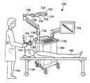
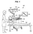
- FIG. 1is a schematic view of the surgical navigation system
- FIG. 1Ais a block diagram of the surgical navigation system of FIG. 1 ;
- FIG. 2is an isometric view of one embodiment of the adapter of the present invention.
- FIG. 3is a side elevational view of the adapter of FIG. 2 ;
- FIG. 4is an end elevational view of the adapter of FIG. 2 ;
- FIG. 5is an end elevational view of the adapter of FIG. 2 from the end opposite FIG. 4 ;
- FIG. 6is an isometric view of the surgical instrument being held by a hand in a non-fixed relationship with adapter of FIG. 2 connected to a navigation tracker;
- FIG. 7is an exploded view of the surgical instrument, adapter, and navigation tracker of FIG. 4 ;
- FIG. 8is a block diagram of a computer program embodying one embodiment of the method of the present invention.
- FIG. 9is a block diagram of a computer program embodying a further embodiment of the method of the present invention.
- FIG. 10is an end elevational view similar to FIG. 5 of an alternative embodiment of the adapter of the present invention.
- FIG. 11is an end elevational view similar to FIG. 5 of a further alternative embodiment of the adapter of the present invention.
- FIG. 12is an end elevational view similar to FIG. 5 of an additional alternative embodiment of the adapter of the present invention.
- FIG. 13is an end elevational view similar to FIG. 5 of a still further alternative embodiment of the adapter of the present invention.
- FIG. 14is an end elevational view similar to FIG. 5 of another further embodiment of the adapter of the present invention.
- FIG. 15is a bottom plan view of the adapter of FIG. 14 ;
- FIG. 16is an isometric view of a surgical drill with the adapter of FIG. 14 in place;
- FIG. 17is an isometric view of a surgical saw with the adapter of FIG. 14 in place;
- FIG. 18is an end elevational view of the adapter similar to FIG. 4 showing the adapter relative to a surgical instrument having a circular cross section;
- FIG. 19is an end elevational view of the adapter similar to FIG. 4 showing the adapter relative to a surgical instrument having a square cross section;
- FIG. 20is an isometric view of a further embodiment of the adapter of the present invention.
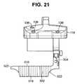
- FIG. 21is a side view of the adapter of FIG. 20 with a tracker attached;
- FIG. 22is a side elevational view of a further embodiment of an adapter device showing the relation with a surgical device
- FIG. 23is a bottom plan view of the adapter of FIG. 22 ;
- FIG. 24is an end elevational view of the adapter of FIG. 22 ;
- FIG. 25is a view similar to FIG. 24 of a further embodiment of the adapter.
- FIG. 26is a view similar to FIG. 24 of another further embodiment of the adapter.
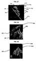
- FIG. 27is a perspective view of one embodiment of a tracking device with integral projections
- FIG. 28is a detailed view of a further embodiment of a tracking device similar to FIG. 27 showing the placement of a surgical device in the grooves;
- FIG. 29is a detailed view of the device of FIG. 28 showing the user manipulating the surgical device relative to the tracking device.
- FIGS. 1 and 1Aare a schematic view and block diagram of the surgical navigation system 100 that includes a display unit 104 , a computer system 106 and a camera array 120 .
- the computer system 106may be housed in a moveable cart 108 .
- the computer system 106may be any type of personal computer having a memory unit 110 , a CPU 112 , and a storage unit 114 .
- the display unit 104can be any conventional display usable with a personal computer.
- the camera array 120is adapted to track a navigation tracker 118 .
- the camera array 120is further adapted to transmit data between the navigation tracker 118 and computer system 106 representing the orientation of the surgical instrument 102 .
- the datais transmitted wirelessly between the navigation tracker 118 and the computer system 106 .
- a system that uses wires to transmit data between the navigation tracker 118 and the computer system 106can be used.
- the camera array 120includes a first camera 122 , a second camera 124 , and a third camera 126 .
- the first, second and third cameras, 122 , 124 , and 126are three CCD cameras adapted to detect the position of infrared signals (IR) generated by the navigation tracker 118 .
- IRinfrared signals
- the camera array 120should be mounted in a stationary position with a sufficient line of sight to the operating room.
- the camera array 120is mounted on a rotatable arm 128 attached to the movable cart 108 .
- the camera array 120may be mounted onto an operating room wall (not shown) or onto other convenient surfaces or locations.
- At least one infrared transceiveris used to communicate data to and from the navigation tracker 118 .
- the sensor array 120includes a first transceiver 130 and a second transceiver 132 located apart from each other. It should be noted that while both the navigation tracker 118 and the transceivers, 130 and 132 , may communicate via infrared signals, those skilled in the art will realize other wireless technologies such as radio frequency signals may be used as well as hardwired systems, so called electromagnetic communication.
- the camera array 120is connected via a cable 134 to a localizer 136 or in some instances directly to the computer.
- the localizer 136cooperates with the camera array 120 to identify the location of a plurality of LED's 138 on the navigation tracker 118 within the line of sight of the sensor array 120 .
- the first, second, and third cameras, 122 , 124 , and 126contain their own orientation data and transmit that data and the orientation data from the plurality of LED's 138 to the localizer 136 .
- the localizer 136converts the raw orientation data into the orientation of individual LED's of the plurality of LED's 138 and transmits this information to the computer system 106 .
- the localizer 136converts the raw data into the orientation of the surgical instrument 102 and transmits this information to the computer system 106 .
- a software program in the computer system 106can convert the raw data into the orientation of the surgical instrument 102 .
- the conversion of the raw datais well known to one skilled in the art and need not be further discussed.
- the computer system 106may be controlled remotely by control buttons (not visible) located on the navigation tracker 118 .
- the computer system 106also includes a keyboard 140 and a pointing device 142 , such as a mouse or any alternative input means for operating the computer system 106 .
- the surgical navigation system 100is used by a surgeon 144 during a procedure on a patient 146 .
- the patient 146is located on a surgical bed or a table 148 .
- the preferred embodiment of the present inventionincludes a surgical instrument 102 non-fixedly coupled to an adapter 116 .
- the adapter 116is, however, coupled to a navigation tracker 118 that is in communication with the sensor array 120 and transceivers 130 and 132 .
- the use of navigation trackers in combination with sensor arrays and transceiversare well known in the art. A more detailed description of such surgical navigation systems are contained in U.S. patent application Ser. No. 10/246,599 filed Sep. 18, 2002, the disclosure of which is hereby incorporated by reference.
- the system, method and adapters of the present inventioncan also be used with other surgical navigation technologies and systems, such as passive optical systems, magnetic based systems, inertial navigation based systems, combination systems, and the like.
- FIGS. 2 to 5show one embodiment of the present invention.
- the adapter 116includes a body 200 , a connector 202 having a first end 204 attached to the body 200 and a second end 206 attached to a docking structure 208 .
- the body 200has a first side 210 , a second side 212 , a first end 214 , and a second end 216 .
- the second side 212defines a geometrical feature 242 .
- the geometrical feature 242is a channel 218 extending along the entire length of the second side 212 .
- the geometrical feature 242 of the adapter 116will define an adapter axis 244 .
- the docking structure 208has a first beveled side 220 , a second beveled side 222 and a surface 224 that has a locking detent 226 .
- the docking structure 208engages cooperating structure on the navigation tracker 118 as discussed hereinafter.
- FIGS. 6 and 7show the embodiment of FIG. 2 in an in-use situation on the surgical instrument 102 with a tracking device 118 .
- the tracking device 118is a known device and has a body 228 . Mounted in fixed positions on the body 228 are the LEDs 138 . Also depending from the body 228 is a mounting bracket 230 having a distal end 232 . The distal end 232 is attached to a pair of walls 234 and 236 . The walls 234 and 236 are shaped to form a slit 238 that will slide over the first and second beveled sides 220 and 222 . The slit 238 will mate in a precision mating arrangement with the docking structure 208 .
- a spring loaded locking structure(not shown) that will allow the surface 224 to slide within the slit 238 until the locking structure reaches the locking detent 226 . At this time, the spring will bias the locking structure into the locking detent 226 and firmly hold the tracking device 118 in fixed relationship with the adapter 116 .
- a button 240is pushed that will release the locking structure within the slit 238 and allow the tracking device to be removed from the adapter 116 .
- the surgical instrument 102has a handle 250 , a shaft 252 , an adapter tip 254 to hold various devices in position, an instrument axis 256 and a striking surface 258 .
- the particular instrument 102 shown in FIGS. 1 , 6 and 7is an impactor used to insert implants attached to the adapter tip 254 during orthopedic surgery. Because the instrument 102 will be struck with a hammer or other impacting device on the impacting surface 258 , it is desirable to navigate the instrument 102 into proper position and then remove the delicate tracking device before the instrument 102 is struck.
- FIG. 6shows a surgeon's hand 270 holding the adapter 116 in a non-fixed coupling with the instrument 102 .
- the adapter 116is held in a reproducible relation to a surgical tool, such as instrument 102 , but is easily removable when the holding force is removed from the adapter. This term includes the situation where the adapter 116 is held in proximity to the instrument 102 by a user's hand and will fall away from the instrument 102 if the hand pressure is removed. Because the shaft 252 has a surface that is co-axial with the instrument axis 256 , the adapter 116 can be moved along the shaft 252 and the relation between the tracker 118 and the instrument axis 256 remains the same.
- FIG. 8is a block diagram of a computer program embodying the method of the present invention.
- the programbegins at a block 400 that determines if the navigation tracker 118 has been activated. If the navigation tracker 118 is not active, the program branches to a block 402 , which displays a message to prompt a user to activate the navigation tracker 118 . The program returns to the block 400 and waits until the surgical navigation system 100 receives a signal that the navigation tracker 118 is active.
- the controlpasses to a block 404 that displays a message that the navigation tracker 118 is active and control then passes to a block 406 that determines if the user needs to identify the effector axis of the surgical instrument.
- the block 408instructs the user to rotate the tool-adapter-tracker combination about the effector axis.
- the block 408will determine the location of the tracker 118 as the combination is rotated and will calculate the relation between the tracker 118 and the effector axis.
- the block 408can instruct a user to invert a tool-adapter-tracker combination where the tool has an effector plane. In this case, the plane of the tool is first placed on a fixed location and the location of the tracker is determined. The tool is then inverted and the plane of the tool is placed at the same location.
- the location effector plane of the tool relative to the trackeris the distance between the first and second locations of the tracker.
- Controlthen passes to a block 410 that records the relation between the tracker 118 and the effector axis or effector plane in the memory unit 110 and displays the effector axis or plane on the display unit 104 . If the user responds “no” in block 406 , control passes to a block 412 that records the axis of the adapter 116 in memory unit 110 and displays the adapter axis on the display unit 104 .
- FIG. 9is a block diagram of another computer program embodying the method of the present invention.
- This embodimentuses a series of databases that have been previously created relative to the potential tools, adapters and trackers that might be used with the surgical navigation system 100 .
- the programbegins at a block 420 that determines if the navigation tracker 118 has been activated. If the navigation tracker 118 is not active, the program branches to a block 422 , which displays a message to prompt a user to activate the navigation tracker 118 .
- the programreturns to the block 420 and waits until the surgical navigation system 100 receives a signal that the navigation tracker 118 is active.
- the controlpasses to a block 424 that displays a message that the navigation tracker 118 is active and control then passes to a block 432 that calculates the orientation of the effector axis.
- This surgical navigation system 100determines the location and orientation of the navigation tracker 118 and the block 426 stores this data in the memory unit 110 .
- a block 428is a database of stored dimensions for a number of adapters. The same may be done for each possible surgical instrument that can be used with the surgical navigation system 100 .
- a block 430is a database of stored dimensions for various surgical instruments and their corresponding effector axes.
- the surgical navigation system 100also will allow a user to manually input data for an adapter or a tool that is not found within the respective database. It is desirable, but not necessary, that the navigation tracker 116 be a smart instrument that can relate its own configuration data to the surgical navigation system when the navigation tracker 118 is activated by the surgical navigation system 100 . Once the surgical navigation system 100 knows the identity of the particular adapter 116 and the surgical instrument 102 , the corresponding databases 428 and 430 are queried for the dimensions of the interface and channel configuration, the dimensions of the surgical instrument and its effector axis. This data may be manually entered or stored before or after the navigation tracker 118 is activated. The surgical navigation system 100 identifies the dimensions of the navigation tracker 118 in a conventional manner.
- the programthen proceeds to calculate the orientation of the effector axis of the surgical instrument 102 from the stored data of the navigation tracker 118 in block 426 and the stored data obtained from the blocks 428 and 430 .
- a block 432calculates the orientation in a conventional fashion using algorithms that are well known and recognized by those skilled in the art.
- a block 434stores the orientation data in the memory unit 110 , and displays the orientation information on the display 104 for use by the operator 144 . Combinations of the uses of databases for various components and the kinematic approach shown in FIG. 8 can also be used.
- FIGS. 10 , 11 , 12 , and 13are alternative shapes of the geometrical feature 242 in FIG. 2 for the adapter 116 .
- the feature 242 a in FIG. 10is circular, while the feature 242 b in FIG. 11 is elliptical.
- the second side 212 of the adapter 116has a wall 300 that is generally perpendicular to a surface 302 that extends from the wall 300 to a periphery 304 of the body 200 .
- the wall 300 and the surface 302form an “L” shaped geometrical feature 242 c .
- the adapter 116 aas shown in FIG.
- FIG. 12is adapted to be used with surgical tools or instruments having a rectangular cross section and the open end of the surface 302 enables the adapter 116 a as shown in FIG. 12 to be used with a wider variety of tools than if the adapter 116 a had a rectangular channel.
- the primary difference between this embodiment and the others previously mentionedis that in addition to an upward force exerted against the surgical instrument 102 to hold the surgical instrument 102 against the surface 302 of the geometrical feature 242 c , a lateral force is also applied to hold the surgical instrument 102 against the wall 300 of the geometrical feature 242 c .
- the adapter 116 acould be used with an instrument or tool that had a handle or shaft wider than the width of the adapter 116 a .
- FIG. 13shows an adapter 116 b that has multiple geometric features 306 and 308 . This arrangement allows the adapter 116 b to be used with different tools without having to remove the navigation tracker from the adapter 116 b.
- FIGS. 14 and 15show a further embodiment of the geometrical feature 242 .
- An adapter 116 chas a bottom surface 112 a and three depending lugs 312 .
- the number of depending lugsis not particularly critical and any number more than 2 can be used. For instance, two longer lugs can be sufficient to hold the adapter in position on the instrument 102 , or four or more smaller lugs can be used to the same effect.
- FIGS. 16 and 17illustrate the use of the adapter 116 c in conjunction with a surgical drill 330 and a surgical saw 360 .
- the surgical drill 330has a drill bit 332 with an effector axis 334 .
- the adapter 116 cshown without the attached navigation tracker for clarity, is held against a top surface 338 of the surgical drill 330 . So long as the top surface 338 is co-linear with the effector axis 334 , the adapter can be moved along the top surface 338 without affecting the relationship between the effector axis 334 and the adapter 116 c .
- This tool-adapter-tracker combinationcan be calibrated using the method shown in FIG.
- a saw blade 362has an effector plane 364 .
- An adapter 116 cis placed on a top surface 366 of the surgical saw 360 .
- the relation of the effector plane 364 to the adapter 116 ccan be determined and calibrated.
- FIG. 18shows a surgical instrument 312 that has a circular cross section.
- the surgical instrument 312has an instrument axis 314 .
- the surgical instrument 312contacts the channel 218 at two points 316 that are equidistant from the channel apex 310 .
- the surgical instrument 312has a radius 318 and the instrument axis 314 is a distance ⁇ 1 from the channel apex 310 .
- the adapter 116can be moved along the length of the surgical instrument 312 and the relation between the instrument axis 314 and the tracker 118 will remain constant.
- the adapter 116 and attached trackerare rotated around the instrument axis.
- the location of the instrument axis 314will remain fixed but the location of the tracker will change.
- the distance between the instrument axis 314 and the trackerwill remain constant.
- the instrument 312 , the adapter 116 and the attached trackercan also be rotated as a unit. Either method provides the basis for the rotation calibration method described above relative to FIG. 8 . The following is an example of how the database method of FIG.
- the surgical navigation system 100can calculate the location of the instrument axis 312 relative to the tracker 118 .
- the surgical navigation system 100will have the position and orientation of the apex 310 of the adapter 116 stored in the adapter database 428 relative to the position and orientation of the navigation tracker 118 that is attached to the adapter 116 .
- the surgical navigation system 100will also have the value ⁇ 1 for the surgical instrument 312 stored in the instrument database. Using these values and the location and orientation of the navigation tracker 118 , the surgical navigation system 100 can calculate the effector axis of the instrument 312 in the block 432 .
- a surgical instrument 312 a as shown in FIG. 19has a square or rectangular cross section that fits snugly against the apex 310 . Since there can be no relative movement between the instrument 312 a and the V shaped channel 218 , the entire combination of the instrument, the adapter and the tracker are rotated around the instrument axis 314 a to perform the calibration as described above relative to FIG. 8 .
- the instrument 312 ahas a known square cross section as shown by the distance ⁇ 2 from an instrument axis 314 a to the apex 310 and is stored in the instrument database 430 as noted above.
- the instrument database 430may include other parameters to enable the surgical navigation system 100 to determine the effector axis or plane.
- One advantage of using a V shaped channel 218 along with a surgical instrument 312 a having a square or rectangular cross sectionis that there is no relative rotation between the adapter 116 and the surgical instrument 312 a.
- the adapter of the present inventionmay be made from any suitable material that is dimensionally stable and capable of being sterilized at least one time. Though it may be desirable that the interface be capable of being repeatedly sterilized, it is also possible that the adapters 116 of the present invention are designed as disposable single use items, which are sterilized upon manufacture, maintained in a sterile condition until use and then discarded. Suitable plastics, which are dimensionally stable and surgically acceptable, such as polyetheretherketone (PEEK), carbon or glass fiber reinforced PEEK, polysulfone, polycarbonate, nylon and mixtures thereof, can be used. In addition, suitable metals that are acceptable for use in surgery such as surgical stainless steel, titanium, tungsten carbide and other similar surgically suitable metals can be used. In one embodiment, the adapter 116 and the channel 218 will be constructed from materials having a hard surface to prevent wearing when the surgical instrument is moved along the surface of the channel 218 .
- PEEKpolyetheretherketone
- suitable metalsthat are acceptable for use in surgery
- FIGS. 20 and 21show a further embodiment of an adapter 500 .
- the adapter 500has a body 502 with a connector 504 having a first end 506 attached to the body 502 and a second end 508 attached to a docking structure 510 .
- the docking structure 510has a center lug 512 and two pins 514 that interfit with the navigation tracker 118 .
- the body 502has a first side 516 , a second side 518 , a first end 520 , and a second end 522 .
- the second side 518defines a geometrical feature 524 .
- the geometrical featureis a pair of arced surfaces 526 and 528 .
- An opening 530 between the arced surfaces 526 and 528reduces the weight of the adapter 500 .
- the arced surfaces 526 and 528will fit against tools that have a circular cross section.
- the body 502also has a series of cutouts 532 that will further reduce the weight of the adapter and may assist the user in grasping the adapter 500 .
- an adapter 600has a body 602 and a connector 604 .
- the connector 604has a first end 606 and a second end 608 that is connected to a docking structure 610 .
- the docking structureis similar to those discussed above and is capable of interfitting with a navigation tracker, such as the navigation tracker 118 .
- the body 602has a first side 612 , a second side 614 , a first end 616 , and a second end 618 .
- Two projections 620 and 622are attached to the second side 614 .
- the second side 614is on a plane 623 .
- Each of the projections 620 and 622has a V-shaped notch 624 and 624 a to receive a surgical device 626 .
- the surgical device 626can be any of the surgical instruments or devices that have been discussed previously.
- the surgical device 626can be an object to be placed within the patient's body, such as a shunt or stint.
- the depth of the notches 624 and 624 aare different to place the surgical device 626 on an angle relative to the second side 614 such that an effector axis 627 of the surgical device 626 will intersect the plane 623 approximately 70 mm from the first end 616 .
- the notches 624 and 624 aeach have two sloping walls 628 that meet at an apex 630 .
- the V-shaped notches 624 and 624 aenable the adapter to be used with different sizes of surgical devices 626 .
- the surgical device 626will rest within the notches 624 and 624 a against the respective walls 628 .
- the walls 628 for each of notches 624 and 624 ashould also lie on the same plane so that the notches 624 and 624 a are a continuation of each other.
- the databasewill know the relative distance from the effector axis of the particular surgical device 626 to the tracking device 118 and the angle of the effector axis 627 relative to the tracking device 118 .
- the distance from the second side 614 to the apex 630 of the notch 624 , ⁇ 3should be large enough so that a user can get their hand between the second side 614 and the surgical device 626 to manipulate the surgical device 626 , if needed.
- FIG. 25shows a further embodiment where each projection 620 and 622 have a U-shaped notch 640 .
- the adapterwill be specially constructed to work with a particular device that has a slightly smaller radius than the radius of the bottom of the U-shaped notch 640 .
- FIG. 26shows another embodiment where a connector 650 , similar to the connector 604 , projects from the body 602 90 degrees from the direction that the connector 604 projects from the body 602 . This alternative arrangement can allow added flexibility for the user to manipulate the surgical device 626 relative to the tracking device 118 .
- FIG. 27shows a further embodiment where a tracking device 700 has integral projections 702 and 704 .
- the projections 702 and 704are directly attached to a body 706 of the tracking device 700 and both are space apart and extend to the side of the tracking device 700 a sufficient distance to allow a user to place their hand within the space between the two projections 702 and 704 .
- the two projections 702 and 704have similar U-shaped notches 708 to receive a surgical device 710 , such as the shunt as shown in FIG. 27 .
- the tracking device 700has integral LEDs 712 that are similar to those described above.
- the tracking device 700also has three switches 714 that are useful to control the surgical navigation system.
- FIGS. 28 and 29show a user manipulating a surgical device 800 relative to a further embodiment of an integral tracking device 802 .
- the usercan place the surgical device 800 into each notch 804 to guide the surgical device to the proper location.
- the surgical deviceis not held firmly within the notches 804 , the user can manipulate the surgical device as needed as shown in FIG. 28 .
Landscapes
- Health & Medical Sciences (AREA)
- Surgery (AREA)
- Life Sciences & Earth Sciences (AREA)
- Engineering & Computer Science (AREA)
- Heart & Thoracic Surgery (AREA)
- Animal Behavior & Ethology (AREA)
- Veterinary Medicine (AREA)
- Biomedical Technology (AREA)
- Nuclear Medicine, Radiotherapy & Molecular Imaging (AREA)
- Medical Informatics (AREA)
- Molecular Biology (AREA)
- Public Health (AREA)
- General Health & Medical Sciences (AREA)
- Pathology (AREA)
- Oral & Maxillofacial Surgery (AREA)
- Robotics (AREA)
- Surgical Instruments (AREA)
- Manipulator (AREA)
Abstract
Description
Claims (30)
Priority Applications (3)
| Application Number | Priority Date | Filing Date | Title |
|---|---|---|---|
| US11/148,520US7771436B2 (en) | 2003-12-10 | 2005-06-09 | Surgical navigation tracker, system and method |
| DE102006026913.6ADE102006026913B4 (en) | 2005-06-09 | 2006-06-09 | Operational navigation tracking device, system and procedure |
| US11/978,262US20090088630A1 (en) | 2003-12-10 | 2008-01-07 | Surgical navigation tracker, system and method |
Applications Claiming Priority (2)
| Application Number | Priority Date | Filing Date | Title |
|---|---|---|---|
| US10/732,553US7873400B2 (en) | 2003-12-10 | 2003-12-10 | Adapter for surgical navigation trackers |
| US11/148,520US7771436B2 (en) | 2003-12-10 | 2005-06-09 | Surgical navigation tracker, system and method |
Related Parent Applications (1)
| Application Number | Title | Priority Date | Filing Date |
|---|---|---|---|
| US10/732,553Continuation-In-PartUS7873400B2 (en) | 2003-12-10 | 2003-12-10 | Adapter for surgical navigation trackers |
Related Child Applications (1)
| Application Number | Title | Priority Date | Filing Date |
|---|---|---|---|
| US11/978,262DivisionUS20090088630A1 (en) | 2003-12-10 | 2008-01-07 | Surgical navigation tracker, system and method |
Publications (2)
| Publication Number | Publication Date |
|---|---|
| US20050288575A1 US20050288575A1 (en) | 2005-12-29 |
| US7771436B2true US7771436B2 (en) | 2010-08-10 |
Family
ID=37887159
Family Applications (2)
| Application Number | Title | Priority Date | Filing Date |
|---|---|---|---|
| US11/148,520Expired - LifetimeUS7771436B2 (en) | 2003-12-10 | 2005-06-09 | Surgical navigation tracker, system and method |
| US11/978,262AbandonedUS20090088630A1 (en) | 2003-12-10 | 2008-01-07 | Surgical navigation tracker, system and method |
Family Applications After (1)
| Application Number | Title | Priority Date | Filing Date |
|---|---|---|---|
| US11/978,262AbandonedUS20090088630A1 (en) | 2003-12-10 | 2008-01-07 | Surgical navigation tracker, system and method |
Country Status (2)
| Country | Link |
|---|---|
| US (2) | US7771436B2 (en) |
| DE (1) | DE102006026913B4 (en) |
Cited By (29)
| Publication number | Priority date | Publication date | Assignee | Title |
|---|---|---|---|---|
| US20100204955A1 (en)* | 2005-11-28 | 2010-08-12 | Martin Roche | Method and system for positional measurement using ultrasonic sensing |
| US20110160583A1 (en)* | 2009-12-31 | 2011-06-30 | Orthosensor | Orthopedic Navigation System with Sensorized Devices |
| US8421642B1 (en) | 2006-08-24 | 2013-04-16 | Navisense | System and method for sensorized user interface |
| US8494805B2 (en) | 2005-11-28 | 2013-07-23 | Orthosensor | Method and system for assessing orthopedic alignment using tracking sensors |
| US8638296B1 (en) | 2006-09-05 | 2014-01-28 | Jason McIntosh | Method and machine for navigation system calibration |
| US20140189508A1 (en)* | 2012-12-31 | 2014-07-03 | Mako Surgical Corp. | Systems and methods for guiding a user during surgical planning |
| US9161799B2 (en) | 2013-01-28 | 2015-10-20 | Warsaw Orthopedic, Inc. | Surgical implant system and method |
| US9189083B2 (en) | 2008-03-18 | 2015-11-17 | Orthosensor Inc. | Method and system for media presentation during operative workflow |
| WO2016081931A1 (en)* | 2014-11-21 | 2016-05-26 | Think Surgical, Inc. | Visible light communication system for transmitting data between visual tracking systems and tracking markers |
| US9592096B2 (en) | 2011-11-30 | 2017-03-14 | Medtech S.A. | Robotic-assisted device for positioning a surgical instrument relative to the body of a patient |
| US9750432B2 (en) | 2010-08-04 | 2017-09-05 | Medtech S.A. | Method for the automated and assisted acquisition of anatomical surfaces |
| US9993273B2 (en) | 2013-01-16 | 2018-06-12 | Mako Surgical Corp. | Bone plate and tracking device using a bone plate for attaching to a patient's anatomy |
| US10405929B1 (en)* | 2015-11-18 | 2019-09-10 | Bradley S. Seltmann | Attachment mechanism for surgical tool tracking system |
| US10449005B2 (en) | 2013-03-20 | 2019-10-22 | Brainlab Ag | Adaptor for receiving a navigated structure which is at least a part of a medical object and method of registering a navigated structure using the adaptor |
| US10531925B2 (en) | 2013-01-16 | 2020-01-14 | Stryker Corporation | Navigation systems and methods for indicating and reducing line-of-sight errors |
| WO2020012479A1 (en) | 2018-07-12 | 2020-01-16 | Deep Health Ltd. | System method and computer program product, for computer aided surgery |
| US10537395B2 (en) | 2016-05-26 | 2020-01-21 | MAKO Surgical Group | Navigation tracker with kinematic connector assembly |
| WO2020172397A1 (en)* | 2019-02-21 | 2020-08-27 | Extremity Development Company, Llc | Instrument bourne optical time of flight kinematic position sensing system for precision targeting and methods of surgery |
| US10993771B2 (en)* | 2016-09-12 | 2021-05-04 | Synaptive Medical Inc. | Trackable apparatuses and methods |
| US11064904B2 (en) | 2016-02-29 | 2021-07-20 | Extremity Development Company, Llc | Smart drill, jig, and method of orthopedic surgery |
| US11291507B2 (en) | 2018-07-16 | 2022-04-05 | Mako Surgical Corp. | System and method for image based registration and calibration |
| EP4005508A1 (en)* | 2017-12-15 | 2022-06-01 | DePuy Synthes Products, Inc. | Orthopedic adapter for an electric impacting tool |
| US11819287B2 (en) | 2018-12-17 | 2023-11-21 | Zimmer Biomet Spine, Inc. | Universal navigation instrument adapter |
| US12059804B2 (en) | 2019-05-22 | 2024-08-13 | Mako Surgical Corp. | Bidirectional kinematic mount |
| US12182956B2 (en) | 2021-07-01 | 2024-12-31 | Microport Orthopedics Holdings Inc. | Systems and methods of using three-dimensional image reconstruction to aid in assessing bone or soft tissue aberrations for orthopedic surgery |
| US12239389B2 (en) | 2021-07-20 | 2025-03-04 | Microport Orthopedics Holdings Inc. | Systems and methods for using photogrammetry to create patient-specific guides for orthopedic surgery |
| US12245825B2 (en) | 2021-09-30 | 2025-03-11 | Microport Orthopedics Holdings Inc. | Systems and methods of using photogrammetry for intraoperatively aligning surgical elements |
| USD1091816S1 (en) | 2023-04-19 | 2025-09-02 | Stryker European Operations Limited | Surgical instrument tracker |
| US12440256B2 (en) | 2024-02-06 | 2025-10-14 | DePuy Synthes Products, Inc. | Orthopedic adapter for an electric impacting tool |
Families Citing this family (24)
| Publication number | Priority date | Publication date | Assignee | Title |
|---|---|---|---|---|
| US20060064005A1 (en)* | 2004-09-23 | 2006-03-23 | Innovative Spinal Technologies | System and method for externally controlled surgical navigation |
| US7840256B2 (en) | 2005-06-27 | 2010-11-23 | Biomet Manufacturing Corporation | Image guided tracking array and method |
| US7643862B2 (en) | 2005-09-15 | 2010-01-05 | Biomet Manufacturing Corporation | Virtual mouse for use in surgical navigation |
| US8165659B2 (en) | 2006-03-22 | 2012-04-24 | Garrett Sheffer | Modeling method and apparatus for use in surgical navigation |
| US8560047B2 (en)* | 2006-06-16 | 2013-10-15 | Board Of Regents Of The University Of Nebraska | Method and apparatus for computer aided surgery |
| US7892165B2 (en)* | 2006-10-23 | 2011-02-22 | Hoya Corporation | Camera calibration for endoscope navigation system |
| US8934961B2 (en) | 2007-05-18 | 2015-01-13 | Biomet Manufacturing, Llc | Trackable diagnostic scope apparatus and methods of use |
| US20080319491A1 (en) | 2007-06-19 | 2008-12-25 | Ryan Schoenefeld | Patient-matched surgical component and methods of use |
| US8571637B2 (en) | 2008-01-21 | 2013-10-29 | Biomet Manufacturing, Llc | Patella tracking method and apparatus for use in surgical navigation |
| EP2105107A1 (en)* | 2008-03-27 | 2009-09-30 | BrainLAB AG | Method for calibrating axial medicinal or medical technical instruments |
| US9023027B2 (en) | 2008-09-30 | 2015-05-05 | Biosense Webster (Israel), Ltd. | Current localization tracker |
| US8456182B2 (en)* | 2008-09-30 | 2013-06-04 | Biosense Webster, Inc. | Current localization tracker |
| US8611985B2 (en) | 2009-01-29 | 2013-12-17 | Imactis | Method and device for navigation of a surgical tool |
| EP2467080B1 (en)* | 2009-08-20 | 2018-04-04 | Brainlab AG | Integrated surgical device combining instrument, tracking system and navigation system |
| US9498231B2 (en) | 2011-06-27 | 2016-11-22 | Board Of Regents Of The University Of Nebraska | On-board tool tracking system and methods of computer assisted surgery |
| CN103764061B (en) | 2011-06-27 | 2017-03-08 | 内布拉斯加大学评议会 | On Tool Tracking System and Computer Assisted Surgery Method |
| CA2851747C (en)* | 2011-10-11 | 2016-07-26 | Ying Ji | Determination method and calibration tool for directional calibration parameters and action direction of surgical instrument |
| CN102551892A (en)* | 2012-01-17 | 2012-07-11 | 王旭东 | Positioning method for craniomaxillofacial surgery |
| CA2910261C (en) | 2012-07-03 | 2020-09-15 | 7D Surgical Inc. | Attachments for tracking handheld implements |
| US10105149B2 (en) | 2013-03-15 | 2018-10-23 | Board Of Regents Of The University Of Nebraska | On-board tool tracking system and methods of computer assisted surgery |
| SE542045C2 (en)* | 2016-05-15 | 2020-02-18 | Ortoma Ab | Calibration object, system, and method calibrating location of instrument in a navigation system |
| CA2983780C (en)* | 2017-10-25 | 2020-07-14 | Synaptive Medical (Barbados) Inc. | Surgical imaging sensor and display unit, and surgical navigation system associated therewith |
| US11690680B2 (en) | 2019-03-19 | 2023-07-04 | Mako Surgical Corp. | Trackable protective packaging for tools and methods for calibrating tool installation using the same |
| EP4011317B1 (en)* | 2020-12-10 | 2023-12-27 | Stryker European Operations Limited | Tracker with switchable radiation characteristics |
Citations (108)
| Publication number | Priority date | Publication date | Assignee | Title |
|---|---|---|---|---|
| JPS5721250A (en) | 1980-07-07 | 1982-02-03 | Shiyuukou Seimitsu Kk | Method of presetting tool position in metal machining device and setting jig used therefor |
| US4383373A (en) | 1980-10-08 | 1983-05-17 | Alain Couturier | Method of and apparatus for calibrating an adjustable jig |
| US4567896A (en) | 1984-01-20 | 1986-02-04 | Elscint, Inc. | Method and apparatus for calibrating a biopsy attachment for ultrasonic imaging apparatus |
| JPS6125531A (en) | 1984-07-13 | 1986-02-04 | 株式会社東芝 | Dummy three-dimensional display apparatus |
| JPS6131129A (en) | 1984-07-25 | 1986-02-13 | 株式会社東芝 | Ultrasonic probe |
| US4722056A (en) | 1986-02-18 | 1988-01-26 | Trustees Of Dartmouth College | Reference display systems for superimposing a tomagraphic image onto the focal plane of an operating microscope |
| EP0326768A2 (en) | 1988-02-01 | 1989-08-09 | Faro Medical Technologies Inc. | Computer-aided surgery apparatus |
| JPH01245108A (en) | 1988-03-28 | 1989-09-29 | Nissan Motor Co Ltd | Calibration method of workpiece positioning device |
| JPH0357466A (en) | 1989-07-27 | 1991-03-12 | Yokogawa Medical Syst Ltd | Control method for positioning device for radiation therapy plan |
| WO1991004711A1 (en) | 1989-10-05 | 1991-04-18 | Diadix S.A. | Local intervention interactive system inside a region of a non homogeneous structure |
| WO1991007726A1 (en) | 1989-11-21 | 1991-05-30 | I.S.G. Technologies Inc. | Probe-correlated viewing of anatomical image data |
| US5050608A (en) | 1988-07-12 | 1991-09-24 | Medirand, Inc. | System for indicating a position to be operated in a patient's body |
| US5056523A (en) | 1989-11-22 | 1991-10-15 | Board Of Regents, The University Of Texas System | Precision breast lesion localizer |
| US5078140A (en) | 1986-05-08 | 1992-01-07 | Kwoh Yik S | Imaging device - aided robotic stereotaxis system |
| WO1992006645A1 (en) | 1990-10-19 | 1992-04-30 | St. Louis University | Surgical probe locating system for head use |
| US5142930A (en) | 1987-11-10 | 1992-09-01 | Allen George S | Interactive image-guided surgical system |
| US5186174A (en) | 1987-05-21 | 1993-02-16 | G. M. Piaff | Process and device for the reproducible optical representation of a surgical operation |
| JPH0549644A (en) | 1991-08-22 | 1993-03-02 | Toshiba Corp | Surgical operation navigation system |
| US5197476A (en) | 1989-03-16 | 1993-03-30 | Christopher Nowacki | Locating target in human body |
| US5198877A (en) | 1990-10-15 | 1993-03-30 | Pixsys, Inc. | Method and apparatus for three-dimensional non-contact shape sensing |
| JPH05111886A (en) | 1991-10-21 | 1993-05-07 | Yaskawa Electric Corp | Method for teaching calibration points of robot manipulator and working method for calibration |
| US5222499A (en) | 1989-11-15 | 1993-06-29 | Allen George S | Method and apparatus for imaging the anatomy |
| US5230623A (en) | 1991-12-10 | 1993-07-27 | Radionics, Inc. | Operating pointer with interactive computergraphics |
| US5251127A (en) | 1988-02-01 | 1993-10-05 | Faro Medical Technologies Inc. | Computer-aided surgery apparatus |
| US5299288A (en) | 1990-05-11 | 1994-03-29 | International Business Machines Corporation | Image-directed robotic system for precise robotic surgery including redundant consistency checking |
| US5309913A (en) | 1992-11-30 | 1994-05-10 | The Cleveland Clinic Foundation | Frameless stereotaxy system |
| WO1994023647A1 (en) | 1993-04-22 | 1994-10-27 | Pixsys, Inc. | System for locating relative positions of objects |
| WO1994024933A1 (en) | 1993-04-26 | 1994-11-10 | St. Louis University | Indicating the position of a surgical probe |
| US5389101A (en) | 1992-04-21 | 1995-02-14 | University Of Utah | Apparatus and method for photogrammetric surgical localization |
| US5392384A (en) | 1991-04-09 | 1995-02-21 | Kabushiki Kaisha Yaskawa Denki | Method of calibrating an industrial robot |
| US5394875A (en) | 1993-10-21 | 1995-03-07 | Lewis; Judith T. | Automatic ultrasonic localization of targets implanted in a portion of the anatomy |
| CA1336451C (en) | 1988-02-01 | 1995-07-25 | Simon Raab | Computer-aided surgery apparatus |
| JPH07194616A (en) | 1993-11-26 | 1995-08-01 | Toshiba Medical Eng Co Ltd | Surgery support system |
| EP0469966B1 (en) | 1990-07-31 | 1995-08-30 | Faro Medical Technologies (Us) Inc. | Computer-aided surgery apparatus |
| JPH07236633A (en) | 1994-03-01 | 1995-09-12 | Toshiba Corp | Biopsy needle positioning method |
| US5471312A (en) | 1991-07-04 | 1995-11-28 | Fanuc Ltd. | Automatic calibration method |
| JPH07323035A (en) | 1994-05-31 | 1995-12-12 | Shimadzu Corp | Position display device for surgical instruments |
| JPH07328016A (en) | 1994-06-14 | 1995-12-19 | Olympus Optical Co Ltd | Surgical manipulator system |
| US5483961A (en) | 1993-03-19 | 1996-01-16 | Kelly; Patrick J. | Magnetic field digitizer for stereotactic surgery |
| JPH0810266A (en) | 1994-06-28 | 1996-01-16 | Toru Hayakawa | Position display device for surgical instruments |
| JPH0838507A (en) | 1994-07-28 | 1996-02-13 | Shimadzu Corp | Position display device for surgical instruments |
| US5494034A (en) | 1987-05-27 | 1996-02-27 | Georg Schlondorff | Process and device for the reproducible optical representation of a surgical operation |
| WO1996011624A2 (en) | 1994-10-07 | 1996-04-25 | St. Louis University | Surgical navigation systems including reference and localization frames |
| US5517990A (en) | 1992-11-30 | 1996-05-21 | The Cleveland Clinic Foundation | Stereotaxy wand and tool guide |
| US5552822A (en) | 1993-11-12 | 1996-09-03 | Nallakrishnan; Ravi | Apparatus and method for setting depth of cut of micrometer surgical knife |
| US5564437A (en) | 1992-12-15 | 1996-10-15 | Universite Joseph Fourier | Method and system for determining the fixation point on the femur of a crossed ligament of the knee |
| US5617857A (en) | 1995-06-06 | 1997-04-08 | Image Guided Technologies, Inc. | Imaging system having interactive medical instruments and methods |
| US5662111A (en) | 1991-01-28 | 1997-09-02 | Cosman; Eric R. | Process of stereotactic optical navigation |
| US5663795A (en) | 1995-09-07 | 1997-09-02 | Virtek Vision Corp. | Method of calibrating laser positions relative to workpieces |
| US5676673A (en) | 1994-09-15 | 1997-10-14 | Visualization Technology, Inc. | Position tracking and imaging system with error detection for use in medical applications |
| US5732703A (en) | 1992-11-30 | 1998-03-31 | The Cleveland Clinic Foundation | Stereotaxy wand and tool guide |
| US5740222A (en) | 1993-11-26 | 1998-04-14 | Kabushiki Kaisha Toshiba | Radiation computed tomography apparatus |
| US5772594A (en) | 1995-10-17 | 1998-06-30 | Barrick; Earl F. | Fluoroscopic image guided orthopaedic surgery system with intraoperative registration |
| US5787886A (en) | 1993-03-19 | 1998-08-04 | Compass International Incorporated | Magnetic field digitizer for stereotatic surgery |
| US5876325A (en) | 1993-11-02 | 1999-03-02 | Olympus Optical Co., Ltd. | Surgical manipulation system |
| US5921992A (en)* | 1997-04-11 | 1999-07-13 | Radionics, Inc. | Method and system for frameless tool calibration |
| US5954648A (en) | 1996-04-29 | 1999-09-21 | U.S. Philips Corporation | Image guided surgery system |
| US5967982A (en) | 1997-12-09 | 1999-10-19 | The Cleveland Clinic Foundation | Non-invasive spine and bone registration for frameless stereotaxy |
| US5987960A (en)* | 1997-09-26 | 1999-11-23 | Picker International, Inc. | Tool calibrator |
| US5999837A (en) | 1997-09-26 | 1999-12-07 | Picker International, Inc. | Localizing and orienting probe for view devices |
| US6006126A (en) | 1991-01-28 | 1999-12-21 | Cosman; Eric R. | System and method for stereotactic registration of image scan data |
| US6021343A (en) | 1997-11-20 | 2000-02-01 | Surgical Navigation Technologies | Image guided awl/tap/screwdriver |
| US6081336A (en) | 1997-09-26 | 2000-06-27 | Picker International, Inc. | Microscope calibrator |
| US6112113A (en) | 1997-07-03 | 2000-08-29 | U.S. Philips Corporation | Image-guided surgery system |
| US6167295A (en) | 1991-01-28 | 2000-12-26 | Radionics, Inc. | Optical and computer graphic stereotactic localizer |
| US6205411B1 (en) | 1997-02-21 | 2001-03-20 | Carnegie Mellon University | Computer-assisted surgery planner and intra-operative guidance system |
| US6266551B1 (en) | 1996-02-15 | 2001-07-24 | Biosense, Inc. | Catheter calibration and usage monitoring system |
| US6273896B1 (en)* | 1998-04-21 | 2001-08-14 | Neutar, Llc | Removable frames for stereotactic localization |
| US6282437B1 (en) | 1998-08-12 | 2001-08-28 | Neutar, Llc | Body-mounted sensing system for stereotactic surgery |
| US6285902B1 (en) | 1999-02-10 | 2001-09-04 | Surgical Insights, Inc. | Computer assisted targeting device for use in orthopaedic surgery |
| US6298262B1 (en) | 1998-04-21 | 2001-10-02 | Neutar, Llc | Instrument guidance for stereotactic surgery |
| US6306126B1 (en) | 1998-09-18 | 2001-10-23 | Stryker Leibinger Gmbh & Co Kg | Calibrating device |
| US20010034530A1 (en) | 2000-01-27 | 2001-10-25 | Malackowski Donald W. | Surgery system |
| US6335617B1 (en) | 1996-05-06 | 2002-01-01 | Biosense, Inc. | Method and apparatus for calibrating a magnetic field generator |
| US20020016599A1 (en)* | 2000-06-09 | 2002-02-07 | Kienzle Thomas C. | Method and apparatus for display of an image guided drill bit |
| US6370411B1 (en) | 1998-02-10 | 2002-04-09 | Biosense, Inc. | Catheter calibration |
| US20020077540A1 (en) | 2000-11-17 | 2002-06-20 | Kienzle Thomas C. | Enhanced graphic features for computer assisted surgery system |
| US20020077543A1 (en) | 2000-06-27 | 2002-06-20 | Robert Grzeszczuk | Method and apparatus for tracking a medical instrument based on image registration |
| US20020077544A1 (en) | 2000-09-23 | 2002-06-20 | Ramin Shahidi | Endoscopic targeting method and system |
| US6428547B1 (en) | 1999-11-25 | 2002-08-06 | Brainlab Ag | Detection of the shape of treatment devices |
| US6434507B1 (en)* | 1997-09-05 | 2002-08-13 | Surgical Navigation Technologies, Inc. | Medical instrument and method for use with computer-assisted image guided surgery |
| US20020133162A1 (en) | 2001-03-17 | 2002-09-19 | Axelson Stuart L. | Tools used in performing femoral and tibial resection in knee surgery |
| US20020133160A1 (en) | 2001-02-28 | 2002-09-19 | Axelson Stuart L. | Systems used in performing femoral and tibial resection in knee surgery |
| US20020133161A1 (en) | 2001-02-28 | 2002-09-19 | Axelson Stuart L. | Methods used in performing femoral and tibial resection in knee surgery |
| US20020133163A1 (en) | 2001-02-28 | 2002-09-19 | Axelson Stuart L. | Apparatus used in performing femoral and tibial resection in knee surgery |
| US6497134B1 (en) | 2000-03-15 | 2002-12-24 | Image Guided Technologies, Inc. | Calibration of an instrument |
| US6511418B2 (en) | 2000-03-30 | 2003-01-28 | The Board Of Trustees Of The Leland Stanford Junior University | Apparatus and method for calibrating and endoscope |
| US6514259B2 (en) | 2001-02-02 | 2003-02-04 | Carnegie Mellon University | Probe and associated system and method for facilitating planar osteotomy during arthoplasty |
| US6517478B2 (en) | 2000-03-30 | 2003-02-11 | Cbyon, Inc. | Apparatus and method for calibrating an endoscope |
| US6542770B2 (en)* | 2000-02-03 | 2003-04-01 | Koninklijke Philips Electronics N.V. | Method of determining the position of a medical instrument |
| US6584339B2 (en) | 2001-06-27 | 2003-06-24 | Vanderbilt University | Method and apparatus for collecting and processing physical space data for use while performing image-guided surgery |
| US20030209096A1 (en) | 2001-01-30 | 2003-11-13 | Z-Kat, Inc. | Tool calibrator and tracker system |
| US6675040B1 (en)* | 1991-01-28 | 2004-01-06 | Sherwood Services Ag | Optical object tracking system |
| US6725080B2 (en)* | 2000-03-01 | 2004-04-20 | Surgical Navigation Technologies, Inc. | Multiple cannula image guided tool for image guided procedures |
| US20050228270A1 (en)* | 2004-04-02 | 2005-10-13 | Lloyd Charles F | Method and system for geometric distortion free tracking of 3-dimensional objects from 2-dimensional measurements |
| US6973202B2 (en)* | 1998-10-23 | 2005-12-06 | Varian Medical Systems Technologies, Inc. | Single-camera tracking of an object |
| US7008430B2 (en)* | 2003-01-31 | 2006-03-07 | Howmedica Osteonics Corp. | Adjustable reamer with tip tracker linkage |
| US20060058644A1 (en)* | 2004-09-10 | 2006-03-16 | Harald Hoppe | System, device, and method for AD HOC tracking of an object |
| US7029477B2 (en)* | 2002-12-20 | 2006-04-18 | Zimmer Technology, Inc. | Surgical instrument and positioning method |
| US20060122630A1 (en)* | 2001-09-14 | 2006-06-08 | Wolfgang Daum | Navigation of medical instrument |
| US20060200025A1 (en)* | 2004-12-02 | 2006-09-07 | Scott Elliott | Systems, methods, and apparatus for automatic software flow using instrument detection during computer-aided surgery |
| US7166114B2 (en)* | 2002-09-18 | 2007-01-23 | Stryker Leibinger Gmbh & Co Kg | Method and system for calibrating a surgical tool and adapter thereof |
| US7213598B2 (en)* | 2002-05-28 | 2007-05-08 | Brainlab Ag | Navigation-calibrating rotationally asymmetrical medical instruments or implants |
| US20070208352A1 (en)* | 1999-04-20 | 2007-09-06 | Surgical Navigation Technologies, Inc. | Instrument Guide System |
| US20080039868A1 (en)* | 2006-07-05 | 2008-02-14 | Aesculap Ag & Co. Kg | Calibration method and calibration device for a surgical referencing unit |
| US20080071140A1 (en)* | 2006-09-18 | 2008-03-20 | Abhishek Gattani | Method and apparatus for tracking a surgical instrument during surgery |
| US20080249394A1 (en)* | 2007-04-03 | 2008-10-09 | The Board Of Trustees Of The Leland Stanford Junior University | Method for improved rotational alignment in joint arthroplasty |
| US20080269602A1 (en)* | 2007-04-24 | 2008-10-30 | Medtronic, Inc. | Method And Apparatus For Performing A Navigated Procedure |
Family Cites Families (7)
| Publication number | Priority date | Publication date | Assignee | Title |
|---|---|---|---|---|
| US6120465A (en)* | 1994-01-24 | 2000-09-19 | Radionics Software Applications, Inc. | Virtual probe for a stereotactic digitizer for use in surgery |
| US7302288B1 (en)* | 1996-11-25 | 2007-11-27 | Z-Kat, Inc. | Tool position indicator |
| US6190395B1 (en)* | 1999-04-22 | 2001-02-20 | Surgical Navigation Technologies, Inc. | Image guided universal instrument adapter and method for use with computer-assisted image guided surgery |
| FR2799112B1 (en)* | 1999-10-01 | 2002-07-19 | Praxim | METHOD FOR RECORDING MEDICAL IMAGES ON A PATIENT AND ASSOCIATED DEVICE |
| US6605095B2 (en)* | 2000-06-13 | 2003-08-12 | Sdgi Holdings, Inc. | Percutaneous needle alignment system and associated method |
| US6932823B2 (en)* | 2003-06-24 | 2005-08-23 | Zimmer Technology, Inc. | Detachable support arm for surgical navigation system reference array |
| US7873400B2 (en)* | 2003-12-10 | 2011-01-18 | Stryker Leibinger Gmbh & Co. Kg. | Adapter for surgical navigation trackers |
- 2005
- 2005-06-09USUS11/148,520patent/US7771436B2/ennot_activeExpired - Lifetime
- 2006
- 2006-06-09DEDE102006026913.6Apatent/DE102006026913B4/enactiveActive
- 2008
- 2008-01-07USUS11/978,262patent/US20090088630A1/ennot_activeAbandoned
Patent Citations (127)
| Publication number | Priority date | Publication date | Assignee | Title |
|---|---|---|---|---|
| JPS5721250A (en) | 1980-07-07 | 1982-02-03 | Shiyuukou Seimitsu Kk | Method of presetting tool position in metal machining device and setting jig used therefor |
| US4383373A (en) | 1980-10-08 | 1983-05-17 | Alain Couturier | Method of and apparatus for calibrating an adjustable jig |
| US4567896A (en) | 1984-01-20 | 1986-02-04 | Elscint, Inc. | Method and apparatus for calibrating a biopsy attachment for ultrasonic imaging apparatus |
| JPS6125531A (en) | 1984-07-13 | 1986-02-04 | 株式会社東芝 | Dummy three-dimensional display apparatus |
| JPS6131129A (en) | 1984-07-25 | 1986-02-13 | 株式会社東芝 | Ultrasonic probe |
| US4722056A (en) | 1986-02-18 | 1988-01-26 | Trustees Of Dartmouth College | Reference display systems for superimposing a tomagraphic image onto the focal plane of an operating microscope |
| US5078140A (en) | 1986-05-08 | 1992-01-07 | Kwoh Yik S | Imaging device - aided robotic stereotaxis system |
| US5186174A (en) | 1987-05-21 | 1993-02-16 | G. M. Piaff | Process and device for the reproducible optical representation of a surgical operation |
| US5494034A (en) | 1987-05-27 | 1996-02-27 | Georg Schlondorff | Process and device for the reproducible optical representation of a surgical operation |
| US5142930A (en) | 1987-11-10 | 1992-09-01 | Allen George S | Interactive image-guided surgical system |
| CA1336451C (en) | 1988-02-01 | 1995-07-25 | Simon Raab | Computer-aided surgery apparatus |
| EP0326768A2 (en) | 1988-02-01 | 1989-08-09 | Faro Medical Technologies Inc. | Computer-aided surgery apparatus |
| US5305203A (en) | 1988-02-01 | 1994-04-19 | Faro Medical Technologies Inc. | Computer-aided surgery apparatus |
| US5251127A (en) | 1988-02-01 | 1993-10-05 | Faro Medical Technologies Inc. | Computer-aided surgery apparatus |
| JPH01245108A (en) | 1988-03-28 | 1989-09-29 | Nissan Motor Co Ltd | Calibration method of workpiece positioning device |
| US5050608A (en) | 1988-07-12 | 1991-09-24 | Medirand, Inc. | System for indicating a position to be operated in a patient's body |
| US5197476A (en) | 1989-03-16 | 1993-03-30 | Christopher Nowacki | Locating target in human body |
| JPH0357466A (en) | 1989-07-27 | 1991-03-12 | Yokogawa Medical Syst Ltd | Control method for positioning device for radiation therapy plan |
| WO1991004711A1 (en) | 1989-10-05 | 1991-04-18 | Diadix S.A. | Local intervention interactive system inside a region of a non homogeneous structure |
| US5222499A (en) | 1989-11-15 | 1993-06-29 | Allen George S | Method and apparatus for imaging the anatomy |
| WO1991007726A1 (en) | 1989-11-21 | 1991-05-30 | I.S.G. Technologies Inc. | Probe-correlated viewing of anatomical image data |
| US5056523A (en) | 1989-11-22 | 1991-10-15 | Board Of Regents, The University Of Texas System | Precision breast lesion localizer |
| US5299288A (en) | 1990-05-11 | 1994-03-29 | International Business Machines Corporation | Image-directed robotic system for precise robotic surgery including redundant consistency checking |
| EP0469966B1 (en) | 1990-07-31 | 1995-08-30 | Faro Medical Technologies (Us) Inc. | Computer-aided surgery apparatus |
| US5198877A (en) | 1990-10-15 | 1993-03-30 | Pixsys, Inc. | Method and apparatus for three-dimensional non-contact shape sensing |
| US5383454B1 (en) | 1990-10-19 | 1996-12-31 | Univ St Louis | System for indicating the position of a surgical probe within a head on an image of the head |
| US5622170A (en) | 1990-10-19 | 1997-04-22 | Image Guided Technologies, Inc. | Apparatus for determining the position and orientation of an invasive portion of a probe inside a three-dimensional body |
| US5851183A (en) | 1990-10-19 | 1998-12-22 | St. Louis University | System for indicating the position of a surgical probe within a head on an image of the head |
| US5891034A (en) | 1990-10-19 | 1999-04-06 | St. Louis University | System for indicating the position of a surgical probe within a head on an image of the head |
| US5383454A (en) | 1990-10-19 | 1995-01-24 | St. Louis University | System for indicating the position of a surgical probe within a head on an image of the head |
| WO1992006645A1 (en) | 1990-10-19 | 1992-04-30 | St. Louis University | Surgical probe locating system for head use |
| US6675040B1 (en)* | 1991-01-28 | 2004-01-06 | Sherwood Services Ag | Optical object tracking system |
| US6006126A (en) | 1991-01-28 | 1999-12-21 | Cosman; Eric R. | System and method for stereotactic registration of image scan data |
| US6167295A (en) | 1991-01-28 | 2000-12-26 | Radionics, Inc. | Optical and computer graphic stereotactic localizer |
| US6275725B1 (en) | 1991-01-28 | 2001-08-14 | Radionics, Inc. | Stereotactic optical navigation |
| US5848967A (en) | 1991-01-28 | 1998-12-15 | Cosman; Eric R. | Optically coupled frameless stereotactic system and method |
| US5662111A (en) | 1991-01-28 | 1997-09-02 | Cosman; Eric R. | Process of stereotactic optical navigation |
| US5392384A (en) | 1991-04-09 | 1995-02-21 | Kabushiki Kaisha Yaskawa Denki | Method of calibrating an industrial robot |
| US5471312A (en) | 1991-07-04 | 1995-11-28 | Fanuc Ltd. | Automatic calibration method |
| JPH0549644A (en) | 1991-08-22 | 1993-03-02 | Toshiba Corp | Surgical operation navigation system |
| JPH05111886A (en) | 1991-10-21 | 1993-05-07 | Yaskawa Electric Corp | Method for teaching calibration points of robot manipulator and working method for calibration |
| US5230623A (en) | 1991-12-10 | 1993-07-27 | Radionics, Inc. | Operating pointer with interactive computergraphics |
| US5389101A (en) | 1992-04-21 | 1995-02-14 | University Of Utah | Apparatus and method for photogrammetric surgical localization |
| US5732703A (en) | 1992-11-30 | 1998-03-31 | The Cleveland Clinic Foundation | Stereotaxy wand and tool guide |
| US5309913A (en) | 1992-11-30 | 1994-05-10 | The Cleveland Clinic Foundation | Frameless stereotaxy system |
| US5517990A (en) | 1992-11-30 | 1996-05-21 | The Cleveland Clinic Foundation | Stereotaxy wand and tool guide |
| US6377839B1 (en)* | 1992-11-30 | 2002-04-23 | The Cleveland Clinic Foundation | Tool guide for a surgical tool |
| US5564437A (en) | 1992-12-15 | 1996-10-15 | Universite Joseph Fourier | Method and system for determining the fixation point on the femur of a crossed ligament of the knee |
| US5483961A (en) | 1993-03-19 | 1996-01-16 | Kelly; Patrick J. | Magnetic field digitizer for stereotactic surgery |
| US5787886A (en) | 1993-03-19 | 1998-08-04 | Compass International Incorporated | Magnetic field digitizer for stereotatic surgery |
| WO1994023647A1 (en) | 1993-04-22 | 1994-10-27 | Pixsys, Inc. | System for locating relative positions of objects |
| US6442416B1 (en) | 1993-04-22 | 2002-08-27 | Image Guided Technologies, Inc. | Determination of the position and orientation of at least one object in space |
| WO1994024933A1 (en) | 1993-04-26 | 1994-11-10 | St. Louis University | Indicating the position of a surgical probe |
| US5394875A (en) | 1993-10-21 | 1995-03-07 | Lewis; Judith T. | Automatic ultrasonic localization of targets implanted in a portion of the anatomy |
| US5876325A (en) | 1993-11-02 | 1999-03-02 | Olympus Optical Co., Ltd. | Surgical manipulation system |
| US5552822A (en) | 1993-11-12 | 1996-09-03 | Nallakrishnan; Ravi | Apparatus and method for setting depth of cut of micrometer surgical knife |
| US5848126A (en) | 1993-11-26 | 1998-12-08 | Kabushiki Kaisha Toshiba | Radiation computed tomography apparatus |
| US5748696A (en) | 1993-11-26 | 1998-05-05 | Kabushiki Kaisha Toshiba | Radiation computed tomography apparatus |
| JPH07194616A (en) | 1993-11-26 | 1995-08-01 | Toshiba Medical Eng Co Ltd | Surgery support system |
| US5740222A (en) | 1993-11-26 | 1998-04-14 | Kabushiki Kaisha Toshiba | Radiation computed tomography apparatus |
| JPH07236633A (en) | 1994-03-01 | 1995-09-12 | Toshiba Corp | Biopsy needle positioning method |
| JPH07323035A (en) | 1994-05-31 | 1995-12-12 | Shimadzu Corp | Position display device for surgical instruments |
| JPH07328016A (en) | 1994-06-14 | 1995-12-19 | Olympus Optical Co Ltd | Surgical manipulator system |
| JPH0810266A (en) | 1994-06-28 | 1996-01-16 | Toru Hayakawa | Position display device for surgical instruments |
| JPH0838507A (en) | 1994-07-28 | 1996-02-13 | Shimadzu Corp | Position display device for surgical instruments |
| US5676673A (en) | 1994-09-15 | 1997-10-14 | Visualization Technology, Inc. | Position tracking and imaging system with error detection for use in medical applications |
| WO1996011624A2 (en) | 1994-10-07 | 1996-04-25 | St. Louis University | Surgical navigation systems including reference and localization frames |
| US6236875B1 (en) | 1994-10-07 | 2001-05-22 | Surgical Navigation Technologies | Surgical navigation systems including reference and localization frames |
| US5617857A (en) | 1995-06-06 | 1997-04-08 | Image Guided Technologies, Inc. | Imaging system having interactive medical instruments and methods |
| US5663795A (en) | 1995-09-07 | 1997-09-02 | Virtek Vision Corp. | Method of calibrating laser positions relative to workpieces |
| US5772594A (en) | 1995-10-17 | 1998-06-30 | Barrick; Earl F. | Fluoroscopic image guided orthopaedic surgery system with intraoperative registration |
| US6266551B1 (en) | 1996-02-15 | 2001-07-24 | Biosense, Inc. | Catheter calibration and usage monitoring system |
| US5954648A (en) | 1996-04-29 | 1999-09-21 | U.S. Philips Corporation | Image guided surgery system |
| US6335617B1 (en) | 1996-05-06 | 2002-01-01 | Biosense, Inc. | Method and apparatus for calibrating a magnetic field generator |
| US6205411B1 (en) | 1997-02-21 | 2001-03-20 | Carnegie Mellon University | Computer-assisted surgery planner and intra-operative guidance system |
| US5921992A (en)* | 1997-04-11 | 1999-07-13 | Radionics, Inc. | Method and system for frameless tool calibration |
| US6112113A (en) | 1997-07-03 | 2000-08-29 | U.S. Philips Corporation | Image-guided surgery system |
| US6434507B1 (en)* | 1997-09-05 | 2002-08-13 | Surgical Navigation Technologies, Inc. | Medical instrument and method for use with computer-assisted image guided surgery |
| US5987960A (en)* | 1997-09-26 | 1999-11-23 | Picker International, Inc. | Tool calibrator |
| US5999837A (en) | 1997-09-26 | 1999-12-07 | Picker International, Inc. | Localizing and orienting probe for view devices |
| US6081336A (en) | 1997-09-26 | 2000-06-27 | Picker International, Inc. | Microscope calibrator |
| US6021343A (en) | 1997-11-20 | 2000-02-01 | Surgical Navigation Technologies | Image guided awl/tap/screwdriver |
| US5967982A (en) | 1997-12-09 | 1999-10-19 | The Cleveland Clinic Foundation | Non-invasive spine and bone registration for frameless stereotaxy |
| US6370411B1 (en) | 1998-02-10 | 2002-04-09 | Biosense, Inc. | Catheter calibration |
| US6298262B1 (en) | 1998-04-21 | 2001-10-02 | Neutar, Llc | Instrument guidance for stereotactic surgery |
| US20010027271A1 (en)* | 1998-04-21 | 2001-10-04 | Franck Joel I. | Instrument guidance for stereotactic surgery |
| US6273896B1 (en)* | 1998-04-21 | 2001-08-14 | Neutar, Llc | Removable frames for stereotactic localization |
| US6282437B1 (en) | 1998-08-12 | 2001-08-28 | Neutar, Llc | Body-mounted sensing system for stereotactic surgery |
| US6306126B1 (en) | 1998-09-18 | 2001-10-23 | Stryker Leibinger Gmbh & Co Kg | Calibrating device |
| US6973202B2 (en)* | 1998-10-23 | 2005-12-06 | Varian Medical Systems Technologies, Inc. | Single-camera tracking of an object |
| US20010036245A1 (en) | 1999-02-10 | 2001-11-01 | Kienzle Thomas C. | Computer assisted targeting device for use in orthopaedic surgery |
| US6285902B1 (en) | 1999-02-10 | 2001-09-04 | Surgical Insights, Inc. | Computer assisted targeting device for use in orthopaedic surgery |
| US6697664B2 (en)* | 1999-02-10 | 2004-02-24 | Ge Medical Systems Global Technology Company, Llc | Computer assisted targeting device for use in orthopaedic surgery |
| US20070208352A1 (en)* | 1999-04-20 | 2007-09-06 | Surgical Navigation Technologies, Inc. | Instrument Guide System |
| US6428547B1 (en) | 1999-11-25 | 2002-08-06 | Brainlab Ag | Detection of the shape of treatment devices |
| US20010034530A1 (en) | 2000-01-27 | 2001-10-25 | Malackowski Donald W. | Surgery system |
| US6542770B2 (en)* | 2000-02-03 | 2003-04-01 | Koninklijke Philips Electronics N.V. | Method of determining the position of a medical instrument |
| US6725080B2 (en)* | 2000-03-01 | 2004-04-20 | Surgical Navigation Technologies, Inc. | Multiple cannula image guided tool for image guided procedures |
| US6497134B1 (en) | 2000-03-15 | 2002-12-24 | Image Guided Technologies, Inc. | Calibration of an instrument |
| US6517478B2 (en) | 2000-03-30 | 2003-02-11 | Cbyon, Inc. | Apparatus and method for calibrating an endoscope |
| US6511418B2 (en) | 2000-03-30 | 2003-01-28 | The Board Of Trustees Of The Leland Stanford Junior University | Apparatus and method for calibrating and endoscope |
| US6478802B2 (en)* | 2000-06-09 | 2002-11-12 | Ge Medical Systems Global Technology Company, Llc | Method and apparatus for display of an image guided drill bit |
| US20020016599A1 (en)* | 2000-06-09 | 2002-02-07 | Kienzle Thomas C. | Method and apparatus for display of an image guided drill bit |
| US20020077543A1 (en) | 2000-06-27 | 2002-06-20 | Robert Grzeszczuk | Method and apparatus for tracking a medical instrument based on image registration |
| US20020077544A1 (en) | 2000-09-23 | 2002-06-20 | Ramin Shahidi | Endoscopic targeting method and system |
| US20020077540A1 (en) | 2000-11-17 | 2002-06-20 | Kienzle Thomas C. | Enhanced graphic features for computer assisted surgery system |
| US7043961B2 (en)* | 2001-01-30 | 2006-05-16 | Z-Kat, Inc. | Tool calibrator and tracker system |
| US20030209096A1 (en) | 2001-01-30 | 2003-11-13 | Z-Kat, Inc. | Tool calibrator and tracker system |
| US6514259B2 (en) | 2001-02-02 | 2003-02-04 | Carnegie Mellon University | Probe and associated system and method for facilitating planar osteotomy during arthoplasty |
| US20020133161A1 (en) | 2001-02-28 | 2002-09-19 | Axelson Stuart L. | Methods used in performing femoral and tibial resection in knee surgery |
| US20020133160A1 (en) | 2001-02-28 | 2002-09-19 | Axelson Stuart L. | Systems used in performing femoral and tibial resection in knee surgery |
| US20020133163A1 (en) | 2001-02-28 | 2002-09-19 | Axelson Stuart L. | Apparatus used in performing femoral and tibial resection in knee surgery |
| US20020133162A1 (en) | 2001-03-17 | 2002-09-19 | Axelson Stuart L. | Tools used in performing femoral and tibial resection in knee surgery |
| US6584339B2 (en) | 2001-06-27 | 2003-06-24 | Vanderbilt University | Method and apparatus for collecting and processing physical space data for use while performing image-guided surgery |
| US20060122630A1 (en)* | 2001-09-14 | 2006-06-08 | Wolfgang Daum | Navigation of medical instrument |
| US7213598B2 (en)* | 2002-05-28 | 2007-05-08 | Brainlab Ag | Navigation-calibrating rotationally asymmetrical medical instruments or implants |
| US7166114B2 (en)* | 2002-09-18 | 2007-01-23 | Stryker Leibinger Gmbh & Co Kg | Method and system for calibrating a surgical tool and adapter thereof |
| US20070175489A1 (en)* | 2002-09-18 | 2007-08-02 | Stryker Leibinger Gmbh & Co. Kg | Method and system for calibrating a surgical tool and adapter therefor |
| US7029477B2 (en)* | 2002-12-20 | 2006-04-18 | Zimmer Technology, Inc. | Surgical instrument and positioning method |
| US7008430B2 (en)* | 2003-01-31 | 2006-03-07 | Howmedica Osteonics Corp. | Adjustable reamer with tip tracker linkage |
| US20050228270A1 (en)* | 2004-04-02 | 2005-10-13 | Lloyd Charles F | Method and system for geometric distortion free tracking of 3-dimensional objects from 2-dimensional measurements |
| US20060058644A1 (en)* | 2004-09-10 | 2006-03-16 | Harald Hoppe | System, device, and method for AD HOC tracking of an object |
| US20060200025A1 (en)* | 2004-12-02 | 2006-09-07 | Scott Elliott | Systems, methods, and apparatus for automatic software flow using instrument detection during computer-aided surgery |
| US20080039868A1 (en)* | 2006-07-05 | 2008-02-14 | Aesculap Ag & Co. Kg | Calibration method and calibration device for a surgical referencing unit |
| US20080071140A1 (en)* | 2006-09-18 | 2008-03-20 | Abhishek Gattani | Method and apparatus for tracking a surgical instrument during surgery |
| US20080249394A1 (en)* | 2007-04-03 | 2008-10-09 | The Board Of Trustees Of The Leland Stanford Junior University | Method for improved rotational alignment in joint arthroplasty |
| US20080269602A1 (en)* | 2007-04-24 | 2008-10-30 | Medtronic, Inc. | Method And Apparatus For Performing A Navigated Procedure |
Non-Patent Citations (14)
| Title |
|---|
| Ahlers et al., "Calibration Requirements and Procedures for a Monitor-Based Augmented Reality System", European Computer Industry Research Centre, pp. 1-32 (Jul. 6, 1995). |
| Bergmann et al., "Calibration of Tracking Systems in a Surgical Environment", IEEE Transactions on Medical Imaging, pp. 1-6 (Oct. 1988). |
| Bucholz et al., "Frameless Stereotactic Ultrasonograph Computerized Medical: Method and Applications", Imaging and Graphics, vol. 18, No. 4, pp. 235-246 (1994). |
| Jiang et al., "Interactive Intraoperative Localization Using an Infrared-Based System", Wayne State University, pp. 84-88 (Oct. 1993). |
| Kadi et al., "Computer-Assisted Neurosurgery System: Wayne State University Hardware and Software Configuration", Computerized Medical Imaging and Graphics, vol. 18, No. 4, pp. 257-271 (1994). |
| Long et al., "An Optical 3D Digitizer for Frameless Stereotactic Surgery", IEEE Computer Graphics and Applications pp. 55-64 (1996). |
| Office Action in U.S. Appl. No. 10/732,553 dated Oct. 7, 2008. |
| Peshkin et al, "Complete Parameter Identification of a Robot From Partial Pose Information" Northwestern University, pp. 1-26. |
| Peshkin et al., "Diagramming Registration Connectivity and Structure", Medicine Meets Virtual Reality III, pp. 1-10 (Jan. 1995). |
| Phillips et al., "Image Guided Orthopaedic Surgery Design and Analysis", Transactions of the Institute of Measurement and Control vol. 17, No. 5, pp. 251-264 (1995). |
| Reinhardt et al., "Micro-Stereometry: A Frameless Computerized Navigating System for Open Microsurgery", Computerized Medical Imaging and Graphics vol. 18, pp. 229-233 (1994). |
| Rose et al, "Object Calibration for Augumented Reality", European Computer-Industry Research Centre GmbH, pp. I-III, 1-18 (Aug. 1995). |
| Stulberg et al., "A Computer-Assisted Total Knee Replacement Surgical System Using a Calibrated Robot", Northwestern University, pp. 1-28. |
| Viergever et al. "An Overview of Medical Image Registration Methods", Imaging Science Department, Imaging Center Utrecht, pp. 1-22. |
Cited By (59)
| Publication number | Priority date | Publication date | Assignee | Title |
|---|---|---|---|---|
| US20100204955A1 (en)* | 2005-11-28 | 2010-08-12 | Martin Roche | Method and system for positional measurement using ultrasonic sensing |
| US8000926B2 (en) | 2005-11-28 | 2011-08-16 | Orthosensor | Method and system for positional measurement using ultrasonic sensing |
| US8494805B2 (en) | 2005-11-28 | 2013-07-23 | Orthosensor | Method and system for assessing orthopedic alignment using tracking sensors |
| US9642571B2 (en) | 2006-08-24 | 2017-05-09 | Orthosensor Inc | System and method for sensorized user interface |
| US8421642B1 (en) | 2006-08-24 | 2013-04-16 | Navisense | System and method for sensorized user interface |
| US8638296B1 (en) | 2006-09-05 | 2014-01-28 | Jason McIntosh | Method and machine for navigation system calibration |
| US9189083B2 (en) | 2008-03-18 | 2015-11-17 | Orthosensor Inc. | Method and system for media presentation during operative workflow |
| US20110160738A1 (en)* | 2009-12-31 | 2011-06-30 | Orthosensor | Operating room surgical field device and method therefore |
| US9011448B2 (en) | 2009-12-31 | 2015-04-21 | Orthosensor Inc. | Orthopedic navigation system with sensorized devices |
| US20110160572A1 (en)* | 2009-12-31 | 2011-06-30 | Orthosensor | Disposable wand and sensor for orthopedic alignment |
| US20110160583A1 (en)* | 2009-12-31 | 2011-06-30 | Orthosensor | Orthopedic Navigation System with Sensorized Devices |
| US9452022B2 (en) | 2009-12-31 | 2016-09-27 | Orthosensor Inc | Disposable wand and sensor for orthopedic alignment |
| US9452023B2 (en) | 2009-12-31 | 2016-09-27 | Orthosensor Inc. | Operating room surgical field device and method therefore |
| US10039476B2 (en) | 2010-08-04 | 2018-08-07 | Medtech S.A. | Method for the automated and assisted acquisition of anatomical surfaces |
| US9750432B2 (en) | 2010-08-04 | 2017-09-05 | Medtech S.A. | Method for the automated and assisted acquisition of anatomical surfaces |
| US10667876B2 (en) | 2011-11-30 | 2020-06-02 | Medtech S.A. | Robotic-assisted device for positioning a surgical instrument relative to the body of a patient |
| US9592096B2 (en) | 2011-11-30 | 2017-03-14 | Medtech S.A. | Robotic-assisted device for positioning a surgical instrument relative to the body of a patient |
| US10159534B2 (en) | 2011-11-30 | 2018-12-25 | Medtech S.A. | Robotic-assisted device for positioning a surgical instrument relative to the body of a patient |
| US9888967B2 (en)* | 2012-12-31 | 2018-02-13 | Mako Surgical Corp. | Systems and methods for guiding a user during surgical planning |
| US11331146B2 (en) | 2012-12-31 | 2022-05-17 | Mako Surgical Corp. | Systems and methods for guiding a user during surgical planning |
| US20140189508A1 (en)* | 2012-12-31 | 2014-07-03 | Mako Surgical Corp. | Systems and methods for guiding a user during surgical planning |
| US12408985B2 (en) | 2012-12-31 | 2025-09-09 | Mako Surgical Corp. | Surgical planning guidance and learning |
| USD1029861S1 (en) | 2012-12-31 | 2024-06-04 | Mako Surgical Corp. | Display screen or portion thereof with graphical user interface |
| US11622800B2 (en) | 2013-01-16 | 2023-04-11 | Mako Surgical Corp. | Bone plate for attaching to an anatomic structure |
| US12102365B2 (en) | 2013-01-16 | 2024-10-01 | Mako Surgical Corp. | Bone plate for attaching to an anatomic structure |
| US10531925B2 (en) | 2013-01-16 | 2020-01-14 | Stryker Corporation | Navigation systems and methods for indicating and reducing line-of-sight errors |
| US11369438B2 (en) | 2013-01-16 | 2022-06-28 | Stryker Corporation | Navigation systems and methods for indicating and reducing line-of-sight errors |
| US9993273B2 (en) | 2013-01-16 | 2018-06-12 | Mako Surgical Corp. | Bone plate and tracking device using a bone plate for attaching to a patient's anatomy |
| US12290321B2 (en) | 2013-01-16 | 2025-05-06 | Stryker Corporation | Navigation systems and methods for indicating and reducing line-of-sight errors |
| US10932837B2 (en) | 2013-01-16 | 2021-03-02 | Mako Surgical Corp. | Tracking device using a bone plate for attaching to a patient's anatomy |
| US9956020B2 (en) | 2013-01-28 | 2018-05-01 | Warsaw Orthopedic, Inc. | Surgical implant system and method |
| US9161799B2 (en) | 2013-01-28 | 2015-10-20 | Warsaw Orthopedic, Inc. | Surgical implant system and method |
| US10449005B2 (en) | 2013-03-20 | 2019-10-22 | Brainlab Ag | Adaptor for receiving a navigated structure which is at least a part of a medical object and method of registering a navigated structure using the adaptor |
| US12213747B2 (en) | 2014-11-21 | 2025-02-04 | Think Surgical, Inc. | Optical communication system |
| US10507063B2 (en) | 2014-11-21 | 2019-12-17 | Think Surgical, Inc. | Visible light communication system for transmitting data between visual tracking systems and tracking markers |
| WO2016081931A1 (en)* | 2014-11-21 | 2016-05-26 | Think Surgical, Inc. | Visible light communication system for transmitting data between visual tracking systems and tracking markers |
| US11172994B1 (en)* | 2015-11-18 | 2021-11-16 | Bradley S. Seltmann | Attachment mechanism for surgical tool tracking system |
| US10405929B1 (en)* | 2015-11-18 | 2019-09-10 | Bradley S. Seltmann | Attachment mechanism for surgical tool tracking system |
| US11064904B2 (en) | 2016-02-29 | 2021-07-20 | Extremity Development Company, Llc | Smart drill, jig, and method of orthopedic surgery |
| US10537395B2 (en) | 2016-05-26 | 2020-01-21 | MAKO Surgical Group | Navigation tracker with kinematic connector assembly |
| US11559358B2 (en) | 2016-05-26 | 2023-01-24 | Mako Surgical Corp. | Surgical assembly with kinematic connector |
| US10993771B2 (en)* | 2016-09-12 | 2021-05-04 | Synaptive Medical Inc. | Trackable apparatuses and methods |
| EP4005508A1 (en)* | 2017-12-15 | 2022-06-01 | DePuy Synthes Products, Inc. | Orthopedic adapter for an electric impacting tool |
| US11925402B2 (en) | 2017-12-15 | 2024-03-12 | Depuy Synthes Products, Inc | Orthopedic adapter for an electric impacting tool |
| US12329432B2 (en) | 2017-12-15 | 2025-06-17 | DePuy Synthes Products, Inc. | Orthopedic adapter for an electric impacting tool |
| WO2020012479A1 (en) | 2018-07-12 | 2020-01-16 | Deep Health Ltd. | System method and computer program product, for computer aided surgery |
| US12402950B2 (en) | 2018-07-12 | 2025-09-02 | Pathkeeper Surgical Ltd | System method and computer program product, for computer aided surgery |
| CN112533556A (en)* | 2018-07-12 | 2021-03-19 | 深度健康有限责任公司 | System method and computer program product for computer-assisted surgery |
| US11806090B2 (en) | 2018-07-16 | 2023-11-07 | Mako Surgical Corp. | System and method for image based registration and calibration |
| US11291507B2 (en) | 2018-07-16 | 2022-04-05 | Mako Surgical Corp. | System and method for image based registration and calibration |
| US11819287B2 (en) | 2018-12-17 | 2023-11-21 | Zimmer Biomet Spine, Inc. | Universal navigation instrument adapter |
| WO2020172397A1 (en)* | 2019-02-21 | 2020-08-27 | Extremity Development Company, Llc | Instrument bourne optical time of flight kinematic position sensing system for precision targeting and methods of surgery |
| US12349982B2 (en) | 2019-02-21 | 2025-07-08 | Surgical Targeted Solutions Inc. | Instrument bourne optical time of flight kinematic position sensing system for precision targeting and methods of surgery |
| US12059804B2 (en) | 2019-05-22 | 2024-08-13 | Mako Surgical Corp. | Bidirectional kinematic mount |
| US12182956B2 (en) | 2021-07-01 | 2024-12-31 | Microport Orthopedics Holdings Inc. | Systems and methods of using three-dimensional image reconstruction to aid in assessing bone or soft tissue aberrations for orthopedic surgery |
| US12239389B2 (en) | 2021-07-20 | 2025-03-04 | Microport Orthopedics Holdings Inc. | Systems and methods for using photogrammetry to create patient-specific guides for orthopedic surgery |
| US12245825B2 (en) | 2021-09-30 | 2025-03-11 | Microport Orthopedics Holdings Inc. | Systems and methods of using photogrammetry for intraoperatively aligning surgical elements |
| USD1091816S1 (en) | 2023-04-19 | 2025-09-02 | Stryker European Operations Limited | Surgical instrument tracker |
| US12440256B2 (en) | 2024-02-06 | 2025-10-14 | DePuy Synthes Products, Inc. | Orthopedic adapter for an electric impacting tool |
Also Published As
| Publication number | Publication date |
|---|---|
| DE102006026913A1 (en) | 2007-04-12 |
| US20050288575A1 (en) | 2005-12-29 |
| DE102006026913B4 (en) | 2025-05-28 |
| US20090088630A1 (en) | 2009-04-02 |
Similar Documents
| Publication | Publication Date | Title |
|---|---|---|
| US7771436B2 (en) | Surgical navigation tracker, system and method | |
| US7873400B2 (en) | Adapter for surgical navigation trackers | |
| CN112206052B (en) | Robotic navigation system for intervertebral implants | |
| US11911112B2 (en) | Robotic navigational system | |
| JP6138699B2 (en) | Tool with integrated navigation and guidance system and associated apparatus and method | |
| EP2869780B1 (en) | Attachments for tracking handheld implements | |
| US7226456B2 (en) | Trackable medical tool for use in image guided surgery | |
| EP2830528B1 (en) | A stabilizer for a surgical instrument | |
| US12396775B2 (en) | System and method for positioning a tracking device | |
| JP2017536909A5 (en) | ||
| US20240423665A1 (en) | Multioptional access device | |
| US20050020909A1 (en) | Display device for surgery and method for using the same | |
| US20020016599A1 (en) | Method and apparatus for display of an image guided drill bit | |
| US20240173082A1 (en) | Generic depth indicator for surgical navigational tools | |
| US20240245411A1 (en) | Systems and methods for transcorporeal microdecompression | |
| US12076091B2 (en) | Robotic navigational system | |
| AU2023413749A1 (en) | Tracking assembly and robotic system | |
| US20210369290A1 (en) | Navigated drill guide | |
| US20240390014A1 (en) | System for guiding a surgical tool comprising an operative axis with respect to an anatomical structure | |
| HK40064640A (en) | Robotic navigational system |
Legal Events
| Date | Code | Title | Description |
|---|---|---|---|
| AS | Assignment | Owner name:STRYKER LEIBINGER GMBH & CO. KG, GERMANY Free format text:ASSIGNMENT OF ASSIGNORS INTEREST;ASSIGNORS:DE LA BARRERA, JOSE LUIS MOCTEZUMA;SARVENSTANI, AMIR;BOEHRINGER, MARKUS;AND OTHERS;REEL/FRAME:016724/0511 Effective date:20050605 | |
| STCF | Information on status: patent grant | Free format text:PATENTED CASE | |
| FPAY | Fee payment | Year of fee payment:4 | |
| AS | Assignment | Owner name:STRYKER EUROPEAN HOLDINGS I, LLC, MICHIGAN Free format text:NUNC PRO TUNC ASSIGNMENT;ASSIGNOR:STRYKER EUROPEAN HOLDINGS VI, LLC;REEL/FRAME:037153/0391 Effective date:20151008 Owner name:STRYKER EUROPEAN HOLDINGS VI, LLC, MICHIGAN Free format text:NUNC PRO TUNC ASSIGNMENT;ASSIGNOR:STRYKER LEIBINGER GMBH & CO. KG;REEL/FRAME:037152/0910 Effective date:20151008 | |
| MAFP | Maintenance fee payment | Free format text:PAYMENT OF MAINTENANCE FEE, 8TH YEAR, LARGE ENTITY (ORIGINAL EVENT CODE: M1552) Year of fee payment:8 | |
| AS | Assignment | Owner name:STRYKER EUROPEAN OPERATIONS HOLDINGS LLC, MICHIGAN Free format text:CHANGE OF NAME;ASSIGNOR:STRYKER EUROPEAN HOLDINGS III, LLC;REEL/FRAME:052860/0716 Effective date:20190226 Owner name:STRYKER EUROPEAN HOLDINGS III, LLC, DELAWARE Free format text:NUNC PRO TUNC ASSIGNMENT;ASSIGNOR:STRYKER EUROPEAN HOLDINGS I, LLC;REEL/FRAME:052861/0001 Effective date:20200519 | |
| MAFP | Maintenance fee payment | Free format text:PAYMENT OF MAINTENANCE FEE, 12TH YEAR, LARGE ENTITY (ORIGINAL EVENT CODE: M1553); ENTITY STATUS OF PATENT OWNER: LARGE ENTITY Year of fee payment:12 |