US7771380B2 - Pressure sensing - Google Patents
Pressure sensingDownload PDFInfo
- Publication number
- US7771380B2 US7771380B2US10/589,353US58935305AUS7771380B2US 7771380 B2US7771380 B2US 7771380B2US 58935305 AUS58935305 AUS 58935305AUS 7771380 B2US7771380 B2US 7771380B2
- Authority
- US
- United States
- Prior art keywords
- pressure
- container
- circuit
- alternating electromagnetic
- blood
- Prior art date
- Legal status (The legal status is an assumption and is not a legal conclusion. Google has not performed a legal analysis and makes no representation as to the accuracy of the status listed.)
- Active, expires
Links
- 239000013060biological fluidSubstances0.000claimsabstractdescription28
- 230000006835compressionEffects0.000claimsabstractdescription7
- 238000007906compressionMethods0.000claimsabstractdescription7
- 238000004891communicationMethods0.000claimsabstractdescription6
- 239000008280bloodSubstances0.000claimsdescription60
- 210000004369bloodAnatomy0.000claimsdescription59
- 230000005672electromagnetic fieldEffects0.000claimsdescription26
- 239000012530fluidSubstances0.000claimsdescription17
- 238000000502dialysisMethods0.000claimsdescription16
- 238000000034methodMethods0.000claimsdescription15
- 239000000758substrateSubstances0.000claimsdescription10
- 239000012528membraneSubstances0.000claimsdescription9
- 239000003990capacitorSubstances0.000claimsdescription8
- 230000003993interactionEffects0.000claimsdescription4
- 238000002615hemofiltrationMethods0.000claimsdescription3
- 238000000926separation methodMethods0.000claimsdescription3
- 230000002612cardiopulmonary effectEffects0.000claims1
- 210000003462veinAnatomy0.000description10
- 239000000385dialysis solutionSubstances0.000description6
- 238000011282treatmentMethods0.000description6
- 206010016717FistulaDiseases0.000description5
- 239000000306componentSubstances0.000description5
- 230000003890fistulaEffects0.000description5
- 238000012360testing methodMethods0.000description5
- 230000008901benefitEffects0.000description4
- 239000012503blood componentSubstances0.000description4
- 210000004204blood vesselAnatomy0.000description4
- 238000011109contaminationMethods0.000description4
- 238000012864cross contaminationMethods0.000description4
- 210000001367arteryAnatomy0.000description3
- 238000004519manufacturing processMethods0.000description3
- 238000005259measurementMethods0.000description3
- 239000002245particleSubstances0.000description3
- 230000004075alterationEffects0.000description2
- 230000017531blood circulationEffects0.000description2
- 239000012141concentrateSubstances0.000description2
- 210000000245forearmAnatomy0.000description2
- 238000001631haemodialysisMethods0.000description2
- 230000000322hemodialysisEffects0.000description2
- 239000007788liquidSubstances0.000description2
- 230000008569processEffects0.000description2
- 230000001681protective effectEffects0.000description2
- 230000004044responseEffects0.000description2
- 239000000126substanceSubstances0.000description2
- XLYOFNOQVPJJNP-UHFFFAOYSA-NwaterSubstancesOXLYOFNOQVPJJNP-UHFFFAOYSA-N0.000description2
- 241000894006BacteriaSpecies0.000description1
- XSQUKJJJFZCRTK-UHFFFAOYSA-NUreaChemical compoundNC(N)=OXSQUKJJJFZCRTK-UHFFFAOYSA-N0.000description1
- 241000700605VirusesSpecies0.000description1
- 238000010521absorption reactionMethods0.000description1
- 238000009825accumulationMethods0.000description1
- 230000008321arterial blood flowEffects0.000description1
- 230000005540biological transmissionEffects0.000description1
- 230000036772blood pressureEffects0.000description1
- 238000009530blood pressure measurementMethods0.000description1
- 239000004202carbamideSubstances0.000description1
- 239000004020conductorSubstances0.000description1
- 230000008878couplingEffects0.000description1
- 238000010168coupling processMethods0.000description1
- 238000005859coupling reactionMethods0.000description1
- 239000013078crystalSubstances0.000description1
- 238000010586diagramMethods0.000description1
- 238000009792diffusion processMethods0.000description1
- 238000006073displacement reactionMethods0.000description1
- 238000001914filtrationMethods0.000description1
- 238000007373indentationMethods0.000description1
- 150000002500ionsChemical class0.000description1
- 239000000463materialSubstances0.000description1
- 239000002184metalSubstances0.000description1
- 238000005459micromachiningMethods0.000description1
- 239000000203mixtureSubstances0.000description1
- 238000000465mouldingMethods0.000description1
- 238000006213oxygenation reactionMethods0.000description1
- 244000052769pathogenSpecies0.000description1
- 230000000149penetrating effectEffects0.000description1
- 238000002616plasmapheresisMethods0.000description1
- 210000002321radial arteryAnatomy0.000description1
- 150000003839saltsChemical class0.000description1
- 230000003068static effectEffects0.000description1
- 238000009966trimmingMethods0.000description1
- 238000007514turningMethods0.000description1
- 238000000108ultra-filtrationMethods0.000description1
- 238000002604ultrasonographyMethods0.000description1
Images


Classifications
- A—HUMAN NECESSITIES
- A61—MEDICAL OR VETERINARY SCIENCE; HYGIENE
- A61M—DEVICES FOR INTRODUCING MEDIA INTO, OR ONTO, THE BODY; DEVICES FOR TRANSDUCING BODY MEDIA OR FOR TAKING MEDIA FROM THE BODY; DEVICES FOR PRODUCING OR ENDING SLEEP OR STUPOR
- A61M1/00—Suction or pumping devices for medical purposes; Devices for carrying-off, for treatment of, or for carrying-over, body-liquids; Drainage systems
- A61M1/36—Other treatment of blood in a by-pass of the natural circulatory system, e.g. temperature adaptation, irradiation ; Extra-corporeal blood circuits
- A61M1/3621—Extra-corporeal blood circuits
- A61M1/3639—Blood pressure control, pressure transducers specially adapted therefor
- A—HUMAN NECESSITIES
- A61—MEDICAL OR VETERINARY SCIENCE; HYGIENE
- A61M—DEVICES FOR INTRODUCING MEDIA INTO, OR ONTO, THE BODY; DEVICES FOR TRANSDUCING BODY MEDIA OR FOR TAKING MEDIA FROM THE BODY; DEVICES FOR PRODUCING OR ENDING SLEEP OR STUPOR
- A61M1/00—Suction or pumping devices for medical purposes; Devices for carrying-off, for treatment of, or for carrying-over, body-liquids; Drainage systems
- A61M1/14—Dialysis systems; Artificial kidneys; Blood oxygenators ; Reciprocating systems for treatment of body fluids, e.g. single needle systems for hemofiltration or pheresis
- A—HUMAN NECESSITIES
- A61—MEDICAL OR VETERINARY SCIENCE; HYGIENE
- A61B—DIAGNOSIS; SURGERY; IDENTIFICATION
- A61B5/00—Measuring for diagnostic purposes; Identification of persons
- A—HUMAN NECESSITIES
- A61—MEDICAL OR VETERINARY SCIENCE; HYGIENE
- A61M—DEVICES FOR INTRODUCING MEDIA INTO, OR ONTO, THE BODY; DEVICES FOR TRANSDUCING BODY MEDIA OR FOR TAKING MEDIA FROM THE BODY; DEVICES FOR PRODUCING OR ENDING SLEEP OR STUPOR
- A61M1/00—Suction or pumping devices for medical purposes; Devices for carrying-off, for treatment of, or for carrying-over, body-liquids; Drainage systems
- A61M1/36—Other treatment of blood in a by-pass of the natural circulatory system, e.g. temperature adaptation, irradiation ; Extra-corporeal blood circuits
- A61M1/3621—Extra-corporeal blood circuits
- A61M1/3622—Extra-corporeal blood circuits with a cassette forming partially or totally the blood circuit
- A61M1/36224—Extra-corporeal blood circuits with a cassette forming partially or totally the blood circuit with sensing means or components thereof
- A—HUMAN NECESSITIES
- A61—MEDICAL OR VETERINARY SCIENCE; HYGIENE
- A61M—DEVICES FOR INTRODUCING MEDIA INTO, OR ONTO, THE BODY; DEVICES FOR TRANSDUCING BODY MEDIA OR FOR TAKING MEDIA FROM THE BODY; DEVICES FOR PRODUCING OR ENDING SLEEP OR STUPOR
- A61M2205/00—General characteristics of the apparatus
- A61M2205/12—General characteristics of the apparatus with interchangeable cassettes forming partially or totally the fluid circuit
- A—HUMAN NECESSITIES
- A61—MEDICAL OR VETERINARY SCIENCE; HYGIENE
- A61M—DEVICES FOR INTRODUCING MEDIA INTO, OR ONTO, THE BODY; DEVICES FOR TRANSDUCING BODY MEDIA OR FOR TAKING MEDIA FROM THE BODY; DEVICES FOR PRODUCING OR ENDING SLEEP OR STUPOR
- A61M2205/00—General characteristics of the apparatus
- A61M2205/35—Communication
- A61M2205/3546—Range
- A61M2205/3569—Range sublocal, e.g. between console and disposable
- Y—GENERAL TAGGING OF NEW TECHNOLOGICAL DEVELOPMENTS; GENERAL TAGGING OF CROSS-SECTIONAL TECHNOLOGIES SPANNING OVER SEVERAL SECTIONS OF THE IPC; TECHNICAL SUBJECTS COVERED BY FORMER USPC CROSS-REFERENCE ART COLLECTIONS [XRACs] AND DIGESTS
- Y10—TECHNICAL SUBJECTS COVERED BY FORMER USPC
- Y10T—TECHNICAL SUBJECTS COVERED BY FORMER US CLASSIFICATION
- Y10T29/00—Metal working
- Y10T29/49—Method of mechanical manufacture
- Y10T29/49002—Electrical device making
- Y10T29/49117—Conductor or circuit manufacturing
Definitions
- the present inventionrelates to management of fluids used in a medical procedure and more specifically to pressure sensing in a biological fluid.
- US patent application 20020007137describes a prior art dialysis pressure sensing system wherein the pressure in an extracorporeal blood circuit is measured with an ordinary pressure transducer.
- the extracorporeal blood circuitis connected to a patient and a dialysis machine.
- the pressure sensoris located within the dialysis machine and operably and structurally connected to the extracorporeal blood circuit.
- the extracorporeal blood circuittypically is in the form of a disposable arrangement there is a risk of cross contamination between patients.
- an air columnin a connector line/column.
- the air columnexerts a backpressure on the blood, thereby preventing blood from getting in contact with the pressure sensor/-machine.
- the dialysis machinenormally comprises pumps of roller type creating a pulsating flow of blood in such a way that blood is penetrating into the connector line to some extent.
- the backpressure exerted on the blood by the air column in the connector lineis overcome and that blood reach a protective filter, protecting the pressure sensor.
- cross contaminationcould occur if this situation reoccurs with another patient connected to the machine and the machine has not been cleaned properly.
- bacteriacould grow in blood residuals at the protective filter.
- leakageAnother problem is that of leakage, which may occur due to operator mistakes during set-up of the system. Needless to say, leakage could be of danger to an operator of the system in case contaminated blood is present in the system. Leakage may also lead to erroneous or less accurate pressure measurements.
- electrical contact problemsmay occur due to presence of spillage (or contamination) of fluids such as blood as well as contamination of particles such as salt crystals and burrs.
- electric connector meansimply that there exist edges, indentations, protrusions etc. in the vicinity of means for transporting fluids, which typically enhances the risk of spillage (or contamination) of fluids as well as particles collecting in the area of the connector means.
- electrical connectors open to touch by operatormay also constitute an added risk of an operator being subject to electric shock.
- An object of the present inventionis to provide a system capable of overcoming problems related to prior art systems.
- the object of the present inventionis achieved in different aspects by way of a device, a use of a device, a system, a use of a system and a method according to the appended claims.
- An inventive device for transporting biological fluid in at least a part of an extracorporeal circuitwhere at least part of the extracorporeal circuit is disposable and comprises at least one pressure sensor configured to be in fluid communication with the biological fluid during use, is characterized in that the at least one pressure sensor is configured for sensing a difference between a pressure of the biological fluid and a reference pressure and comprises an electric circuit that is configured to be energized by an applied alternating first electromagnetic field and configured to communicate information indicative of a pressure from the pressure sensor via a second alternating electromagnetic field.
- the first and second alternating electromagnetic fieldsare one and the same electromagnetic field and also in an embodiment, the first and second alternating electromagnetic fields are in the radio frequency range.
- the senorcomprises a compressible container, the compression or expansion of which is indicative of the pressure.
- the containeris open, i.e. configured with an opening or passage etc., to introduce atmospheric pressure into the container.
- the pressure sensormay include components in the form of a capacitance and/or an inductance, of which components at least one is a variable component which varies with the relative compression and/or expansion of the container, said capacitance and/or inductance being part of a resonance circuit.
- variable capacitance or the variable inductanceis measured. From earlier measurements, i.e. calibration measurements, of the variable components dependence of the pressure the pressure may be determined.
- the compressible containermay include a gas such as air at any known pressure, i.e. a reference pressure in a closed container. Thereby the container may have a known fixed pressure therein, so as to have a reference.
- the sensormay be tailored to have any predetermined resonance frequency in an unaffected state. This may be used in an identification procedure by way of radio frequency measurements, in order to provide for identifying between different disposables used in different applications, such as dialyser, cassette, bloodline, ultrafilter, tube, connector, container, chamber, fluid bag, blood bag, collection bags, pump segment part of lineset, oxygenator etc.
- a system for managing biological fluidscomprises a device with at least one pressure sensor as discussed above, at least one transmitter configured to transmit an alternating electromagnetic field to the at least one sensor in the device, at least one receiver configured to receive radio frequency information from the device, wherein the received information is indicative of at least one pressure sensed by the device, and a control unit configured to control the transmitter and the receiver.
- the at least one sensoris located in close proximity, e.g. 5 to 40 mm, to the at least one transmitter and the at least one receiver.
- An advantage of the inventionis that, by disposing with the need for structurally connecting a pressure sensor to an extracorporeal blood circuit, thereby minimizing the air-blood interface, risks of cross contamination between patients and/or operators are avoided.
- Another advantageis that it is easy to set-up and thereby avoiding risks of leakage, which may be dangerous to an operator of the system.
- Yet another advantage of the present inventionis that it provides an integrated pressure sensor which is sufficiently inexpensive to allow each device to be disposed of after each use.
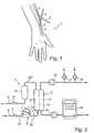
- FIG. 1shows schematically an extracorporeal blood circuit connected to a patient.
- FIG. 2shows schematically an extracorporeal blood circuit comprising a device according to an embodiment of the present invention.
- FIG. 3shows schematically a part of an extracorporeal blood circuit comprising a device with a sensor according to an embodiment of the present invention.
- FIG. 4shows part of FIG. 3 in larger scale.
- FIGS. 5 a - 5 eshow schematically a device comprising a pressure sensor.
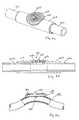
- FIGS. 6 a and 6 bshow a tube mounted pressure sensor according to an embodiment of the present invention.
- FIG. 6 cshows a tube mounted pressure sensor according to an embodiment of the present invention.
- FIGS. 7 a and 7 bshow a system according to the present invention.
- FIGS. 8 a - 8 cshow a respective system according to the present invention.
- the inventionwill be described initially by way of illustration of an extracorporeal blood circuit during the process of dialysis followed by a description of pressure sensors and concluding with a description of a system comprising a blood circuit, pressure sensors, a transmitter and a receiver.
- FIG. 1discloses a forearm 1 of a human patient.
- the forearmcomprises an artery 2 , in this case the radial artery, and a vein 3 , in this case the cephalic vein. Openings are surgically created in the artery 2 and the vein 3 and the openings are connected to form a fistula 4 , in which the arterial blood flow is cross-circuited to the vein. Due to the fistula, the blood flow through the artery and vein is increased and the vein forms a thickened area downstream of the connecting openings. When the fistula has matured after a few months the vein is thicker and may be punctured repeatedly. Normally, the thickened vein area is called a fistula. As the skilled person will realize, an artificial vein may also be used.
- An arterial needle 5is placed in the fistula, in the enlarged vein close to the connected openings and a venous needle 6 is placed downstream of the arterial needle, normally at least five centimeters downstream thereof.
- the needlesare connected to a tube system 7 shown in FIG. 2 , forming an extracorporeal circuit comprising a blood pump 8 , such as may be found in a dialysis circuit.
- the blood pumptransfers blood from the blood vessel, through the arterial needle, the extracorporeal circuit, the venous needle and back into the blood vessel.
- the extracorporeal blood circuit 7 shown in FIG. 2further comprises an arterial clamp 9 and a venous clamp 10 for isolating the patient should an error occur.
- a dialyzer 11Downstream of pump 8 is a dialyzer 11 comprising a blood compartment 12 and a dialysis fluid compartment 13 separated by a semi permeable membrane 14 . Further downstream of the dialyzer is a drip chamber 15 , separating air from the blood therein.
- Bloodpasses from the arterial needle past the arterial clamp 9 to the blood pump 8 .
- the blood pumpdrives the blood through the dialyzer 11 and further via the drip chamber 15 and past the venous clamp 10 back to the patient via the venous needle.
- the drip chambermay comprise air or air bubbles.
- the dialysis compartment 13 of the dialyzer 11is provided with dialysis fluid via a first pump 16 , which obtains dialysis fluid from a source of pure water, normally RO-water, and one or several concentrates of ions, metering pumps 17 and 18 being shown for metering such concentrates.
- a source of pure waternormally RO-water
- metering pumps 17 and 18being shown for metering such concentrates.
- An exchange of substances between the blood and the dialysis fluidtakes place in the dialyzer through the semi permeable membrane.
- ureais passed from the blood, through the semi permeable membrane and to the dialysis fluid present at the other side of the membrane.
- the exchangemay take place by diffusion under the influence of a concentration gradient, so called hemodialysis, and/or by convection due to a flow of liquid from the blood to the dialysis fluid, so called ultra-filtration, which is an important feature of hemodia-filtration or hemofiltration.
- FIG. 3shows schematically a section of a part of a blood circuit 30 with a pressure sensor 323 according to the present invention.
- the sensor 323may be attached inside a tubing line such as line 70 in FIG. 2 after the pump 8 leading to the dialyser, as indicated by reference numeral 23 ′′ in FIG. 2 .
- the sensor 323may be arranged in a tubing line 70 before the pump 8 , as indicated by reference numeral 23 ′ in FIG. 2 .
- the sensor 23may be arranged after the dialyzer at reference numeral 23 ′′′ or in a drip chamber such as drip chamber 15 in FIG. 2 .
- the pressure sensor 323comprises a container 25 with a compressible wall 24 .
- a hole 35 in the wall 32 of the blood circuitensures that the pressure within the container 25 is equal to atmospheric pressure.
- a resonance circuitis enclosed by the compressible container and comprises a variable capacitor 26 and an inductor 27 .
- the variable capacitormay have in one embodiment a number of interdigital conductors 28 in the form of fingers arranged on two opposing metal electrodes.
- a first of the electrodes 29may be arranged on the compressible wall 24 while a second of the electrodes 31 may be fixed in relation to the wall 32 of the blood circuit, e.g. may be affixed to an interior wall of a tubing line 70 or a drip chamber 15 .
- the compressible wall of the containerwill move and accordingly the first electrode 29 and the second electrode 31 will move in relation to each other and thus the capacitance will vary.
- the resonance frequency of the resonance circuit constituted by the capacitor and the inductorwill then vary in accordance with the capacitance of the capacitor.
- an exciter antenna 33 in FIG. 3is arranged connected to a tunable oscillator 34 which may be controlled by a control unit 39 .
- the oscillatormay drive the antenna to influence the electromagnetic field at one or more different frequencies.
- the control unit 39may use the grid-dip oscillator technique according to which technique the oscillator frequency is swept over the resonance frequency of the sensor, or other techniques for analyzing resonance frequencies of LC circuits.
- the oscillatoris inductively coupled to the sensor and at the resonance frequency the sensor will be energized and thereby drain energy from the external circuit.
- a current-dip in the oscillator circuitmay then be detected.
- the resonance frequency of the oscillator circuitmay then be detected and may be transformed into a pressure by an established, e.g. calibrated, relationship between the frequency of the dip frequency and the fluid pressure, i.e. the difference between blood pressure and atmospheric pressure.
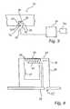
- FIG. 5 ashows the sensor 500 in perspective view
- FIGS. 5 b - dshows the sensor 500 in cross section and forming part of a wall 530 of an extracorporeal blood circuit having an inside surface 531 , being in contact with the blood, and an outside surface 532 , being in contact with the outside atmosphere.
- the sensor 500comprises a substrate 501 on which a lid 502 is arranged.
- a cavity 503is formed between the substrate 501 and the lid 502 , whereby the substrate 501 and the lid 502 form walls of the cavity 503 , defining a container.
- the substrate 501 and the lid 502are made of an electrically isolating material and the cavity 503 has been formed by way of, e.g., micro machining, as is known in the art.
- the cavity 503is in pressure communication with the surroundings by means of a hole 535 in the substrate 501 in the sense that exchange of gas, i.e. air, is possible between the cavity 503 and the outside of the cavity 503 .
- the containeris also compressible, where the term compressible is used in the meaning that the volume of the container may increase as well as decrease depending on the pressure in the extracorporeal circuit.
- a first electrode 504 and a second electrode 505are arranged on two opposing walls of the cavity 503 forming a capacitive arrangement. These electrodes 504 , 505 form, together with an inductor 506 , a resonance circuit similar to the one described above in connection with FIGS. 3 and 4 .
- FIG. 5 cillustrates a situation where the sensor 500 is located in an environment in which the pressure in the extracorporeal circuit is higher than the pressure inside the cavity 503 , i.e. higher than atmospheric pressure. This leads to a net pressure force 510 acting on the lid 502 resulting in a decrease of the volume of the cavity 503 . Consequently, the two electrodes 504 , 505 are brought closer to each other, changing the capacitance of the electrode arrangement and thereby changing the resonance frequency of the resonance circuit.
- FIG. 5 dillustrates a situation where the sensor 500 is located in an environment in which the pressure in the extracorporeal circuit is lower than the pressure inside the cavity 503 , i.e. lower than atmospheric pressure. This leads to a net pressure force 520 acting on the lid 502 resulting in an increase of the volume of the cavity 503 . Consequently, the two electrodes 504 , 505 are brought further away from each other, changing the capacitance of the electrode arrangement and thereby changing the resonance frequency of the resonance circuit.
- FIG. 5 eillustrates schematically an alternative embodiment of a device comprising a sensor configuration.
- a sensor 551is mounted, e.g. glued or welded, on the inside wall 550 of a container for a biological fluid, for example a blood container with, e.g., rigid walls.
- electrodes 554 and 565 and an inductor 566are located on a sensor lid 554 and a substrate 561 , respectively.
- a cavity 553is formed by the lid 552 and the substrate 561 .
- the cavity 553is in pressure communication with the outside of the container for biological fluid by means of a hole 555 .
- a pressure differences between the cavity and the inside of the container for biological fluidresults in flexing of the lid 552 and consequent relative displacement of the electrodes 554 and 565 .
- a pressure sensor 601similar to the sensors described above in connection with FIGS. 5 a - e , comprises a cavity 603 and a hole 635 for allowing the cavity 603 to obtain atmospheric pressure.
- a part of an electrode pattern 605is formed on the sensor 601 .
- the sensor 601is attached to a tube 602 , of which only a short section is shown, by way of a housing 610 .
- the difference between a pressure of a fluid within the tube 602 and the atmospheric pressureis sensed via a membrane 612 as described above in connection with FIGS. 5 a - e.
- the devicei.e. housing and sensor described above in FIGS. 6 a and 6 b , is manufactured, for example, by way of techniques that employ insert molding.
- a pressure sensor 681similar to the sensors described above in connection with FIGS. 5 a - e , comprises a cavity 683 and a hole 685 for allowing the cavity 683 to obtain atmospheric pressure. A part of an electrode pattern is formed on the sensor 681 .
- the sensor 681is attached to a tube 682 , of which only a short section is shown, at a location where the tube 682 is provided with a hole 690 as described, e.g., in the international patent application published with number WO 00/72747.
- the difference between a pressure of a fluid within the tube 682 and the atmospheric pressureis sensed as described above in connection with FIGS. 5 a - 5 e.
- the system 701comprises a device 703 , such as a cassette, which forms part of an extra-corporeal blood circuit 711 , 712 .
- Two pressure sensors 702are arranged in a side wall of the device 703 , the arrangement being such that the sensor is mounted flush with both an inside surface and an outside surface of the wall of the device 703 . It is to be noted, however, that it is not necessary that the sensor is mounted flush with the surfaces.
- the device 703is arranged at a dialysis apparatus 704 , only a part of which is shown in FIGS. 7 a and 7 b , secured by means of mechanical coupling devices 708 , 709 .
- a dialysis apparatus 704Within the dialysis apparatus 704 is an electromagnetic wave transmitter and a receiver located, schematically illustrated by a coil structure 705 . The transmitter and receiver is controlled by a control unit (not shown) within the apparatus 704 .
- FIGS. 8 a - cillustrate schematically, by way of a respective block diagram, systems according to the present invention.
- the systemsmay for example form part, as described above, of a dialysis machine of which only a respective side wall 806 , 826 and 846 is illustrated.
- the systemsare controlled by means of a respective controller 801 , 821 and 841 .
- a first tunable oscillator 808 connected to a first transmitting and receiving antenna 810communicates by way of a first alternating electromagnetic field with a first sensor 802 .
- a second tunable oscillator 812 connected to a second transmitting and receiving antenna 814communicates by way of a second alternating electromagnetic field with a second sensor 804 .
- the tunable oscillators 808 , 812thereby provide a respective signal to the controller 801 indicative of the conditions sensed by the sensors 802 and 804 , respectively.
- a transmitter 828 connected to a transmitting antenna 830generates, i.e. transmits, an alternating electromagnetic field which interacts with a sensor 822 .
- a receiver 832receives, via a receiving antenna 834 , the alternating electromagnetic field, as modified by interaction with the sensor 822 , and thereby provides a signal to the controller 821 indicative of the conditions sensed by the sensor 822 .
- a transmitter 848 connected to an antenna 850generates, i.e. transmits, an alternating electromagnetic field which interacts with a sensor 842 .
- a receiver 852receives, via the same antenna 850 , the alternating electromagnetic field, as modified by interaction with the sensor 842 , and thereby provides a signal to the controller 841 indicative of the conditions sensed by the sensor 842 .
- the testing pressuremay be applied in a number of different ways, for example as a static pressure in a pressure chamber.
- the calibration at manufacturing and/or at the beginning of use at startup of a dialysis sessioncan also provide for ensuring that the pressure sensor is working. This can be a function test like process to see if a proper response to the application of varying pressures by the blood pump or other mechanical alteration.
- the mechanical alterationmay be the appliance of a mechanical force to test the electronic response frequency.
- the force for altering the sensor mechanicallymay be applied, e.g., by applying an ultrasound wave on the sensor.
- the resonant sensor described abovemay be modified in that the inductance is made variable while the capacitance is fixed.
- the device for transporting biological fluidmay be used in other extracorporeal management and/or treatments of biological fluids than specified above.
- Such other extracorporeal management and/or treatmentsmay include: separation of blood into blood components; treatment to reduce pathogens such as viruses in biological fluids; absorption of specific cells or substances in blood; cell sorting and treatment of selected cells.
Landscapes
- Health & Medical Sciences (AREA)
- Heart & Thoracic Surgery (AREA)
- Vascular Medicine (AREA)
- Life Sciences & Earth Sciences (AREA)
- General Health & Medical Sciences (AREA)
- Veterinary Medicine (AREA)
- Engineering & Computer Science (AREA)
- Biomedical Technology (AREA)
- Public Health (AREA)
- Animal Behavior & Ethology (AREA)
- Anesthesiology (AREA)
- Hematology (AREA)
- Cardiology (AREA)
- Physics & Mathematics (AREA)
- Biophysics (AREA)
- Pathology (AREA)
- Medical Informatics (AREA)
- Molecular Biology (AREA)
- Surgery (AREA)
- Emergency Medicine (AREA)
- Urology & Nephrology (AREA)
- External Artificial Organs (AREA)
- Measuring And Recording Apparatus For Diagnosis (AREA)
Abstract
Description
Claims (38)
Priority Applications (2)
| Application Number | Priority Date | Filing Date | Title |
|---|---|---|---|
| US10/589,353US7771380B2 (en) | 2004-02-12 | 2005-02-11 | Pressure sensing |
| US11/808,287US20070261496A1 (en) | 2004-02-12 | 2007-06-08 | Pressure sensing |
Applications Claiming Priority (6)
| Application Number | Priority Date | Filing Date | Title |
|---|---|---|---|
| US54420504P | 2004-02-12 | 2004-02-12 | |
| SE0400330 | 2004-02-12 | ||
| SE0400330ASE0400330D0 (en) | 2004-02-12 | 2004-02-12 | Pressure sensing |
| SE0400330-7 | 2004-02-12 | ||
| US10/589,353US7771380B2 (en) | 2004-02-12 | 2005-02-11 | Pressure sensing |
| PCT/SE2005/000184WO2005077262A1 (en) | 2004-02-12 | 2005-02-11 | Pressure sensing |
Publications (2)
| Publication Number | Publication Date |
|---|---|
| US20070179433A1 US20070179433A1 (en) | 2007-08-02 |
| US7771380B2true US7771380B2 (en) | 2010-08-10 |
Family
ID=31974218
Family Applications (2)
| Application Number | Title | Priority Date | Filing Date |
|---|---|---|---|
| US10/589,353Active2026-08-14US7771380B2 (en) | 2004-02-12 | 2005-02-11 | Pressure sensing |
| US11/808,287AbandonedUS20070261496A1 (en) | 2004-02-12 | 2007-06-08 | Pressure sensing |
Family Applications After (1)
| Application Number | Title | Priority Date | Filing Date |
|---|---|---|---|
| US11/808,287AbandonedUS20070261496A1 (en) | 2004-02-12 | 2007-06-08 | Pressure sensing |
Country Status (9)
| Country | Link |
|---|---|
| US (2) | US7771380B2 (en) |
| EP (1) | EP1713383B1 (en) |
| KR (1) | KR101158596B1 (en) |
| CN (1) | CN100431483C (en) |
| AU (1) | AU2005212146B2 (en) |
| CA (1) | CA2549067C (en) |
| ES (1) | ES2525468T3 (en) |
| SE (1) | SE0400330D0 (en) |
| WO (1) | WO2005077262A1 (en) |
Cited By (15)
| Publication number | Priority date | Publication date | Assignee | Title |
|---|---|---|---|---|
| US20130233777A1 (en)* | 2009-05-29 | 2013-09-12 | Emd Millipore Corporation | Disposable Tangential Flow Filtration Liner with Sensor Mount |
| US9328969B2 (en) | 2011-10-07 | 2016-05-03 | Outset Medical, Inc. | Heat exchange fluid purification for dialysis system |
| US9402945B2 (en) | 2014-04-29 | 2016-08-02 | Outset Medical, Inc. | Dialysis system and methods |
| US9442036B2 (en) | 2008-06-26 | 2016-09-13 | Gambro Lundia Ab | Methods and devices for monitoring the integrity of a fluid connection |
| US9545469B2 (en) | 2009-12-05 | 2017-01-17 | Outset Medical, Inc. | Dialysis system with ultrafiltration control |
| US20170021084A1 (en)* | 2014-05-15 | 2017-01-26 | Novalung Gmbh | Medico-technical measuring device and measuring method |
| US9649420B2 (en) | 2014-09-12 | 2017-05-16 | Easydial, Inc. | Portable hemodialysis machine and disposable cartridge with flow sensor |
| US9808567B2 (en) | 2012-12-14 | 2017-11-07 | Gambro Lundia Ab | Diaphragm repositioning for pressure pod using position sensing |
| US10463306B2 (en) | 2014-05-15 | 2019-11-05 | Novalung Gmbh | Medical measuring system and method for production of the measuring system |
| US10814054B2 (en) | 2015-10-23 | 2020-10-27 | Novalung Gmbh | Intermediate element for a medical extracorporeal fluid line, and system and method associated therewith |
| US10980929B2 (en) | 2014-09-12 | 2021-04-20 | Diality Inc. | Hemodialysis system with ultrafiltration controller |
| US11534537B2 (en) | 2016-08-19 | 2022-12-27 | Outset Medical, Inc. | Peritoneal dialysis system and methods |
| US11724013B2 (en) | 2010-06-07 | 2023-08-15 | Outset Medical, Inc. | Fluid purification system |
| US12201762B2 (en) | 2018-08-23 | 2025-01-21 | Outset Medical, Inc. | Dialysis system and methods |
| US12390565B2 (en) | 2019-04-30 | 2025-08-19 | Outset Medical, Inc. | Dialysis systems and methods |
Families Citing this family (47)
| Publication number | Priority date | Publication date | Assignee | Title |
|---|---|---|---|---|
| DE10321099A1 (en)* | 2003-05-09 | 2004-11-25 | Cgs Sensortechnik Gmbh | Pressure measuring device |
| DE102005008698A1 (en)* | 2005-02-25 | 2006-10-26 | Dräger Medical AG & Co. KG | Device for measuring a volume flow with inductive coupling |
| US7845239B1 (en)* | 2006-03-24 | 2010-12-07 | Polysensors Inc. | Disposable flow chamber electro-magnetic flow sensor |
| US8449487B2 (en)* | 2006-12-01 | 2013-05-28 | Gambro Lundia Ab | Blood treatment apparatus |
| US10463778B2 (en) | 2007-02-09 | 2019-11-05 | Baxter International Inc. | Blood treatment machine having electrical heartbeat analysis |
| US8152751B2 (en) | 2007-02-09 | 2012-04-10 | Baxter International Inc. | Acoustic access disconnection systems and methods |
| DE102008010948B4 (en) | 2008-02-25 | 2013-10-17 | Fresenius Medical Care Deutschland Gmbh | Method for calibrating a sensor within a chamber; Sensor, disposable and treatment device with such a sensor |
| US9370324B2 (en) | 2008-11-05 | 2016-06-21 | Fresenius Medical Care Holdings, Inc. | Hemodialysis patient data acquisition, management and analysis system |
| IT1392256B1 (en)* | 2008-12-05 | 2012-02-22 | Illinois Tool Works | PRESSURE SENSOR MODIFIED TO DETECT OPERATIONAL PARAMETERS OF A APPLIANCE EQUIPPED WITH A RELATIVELY MOBILE COMPONENT |
| US8088091B2 (en) | 2009-03-09 | 2012-01-03 | New Jersey Institute Of Technology | No clog shunt using a compact fluid drag path |
| DK2229967T3 (en)* | 2009-03-17 | 2020-06-15 | Hoffmann La Roche | Cannula collection and outpatient infusion system with a pressure sensor made of stacked coplanar layers |
| DE102009001901A1 (en)* | 2009-03-26 | 2010-09-30 | Robert Bosch Gmbh | Blood treatment device |
| US8591448B2 (en)* | 2009-05-13 | 2013-11-26 | Haemonetics Corporation | Pressure monitoring within a fluid cassette |
| JP5506244B2 (en)* | 2009-05-27 | 2014-05-28 | キヤノン株式会社 | Capacitive electromechanical transducer |
| KR101707701B1 (en) | 2009-06-26 | 2017-02-16 | 감브로 룬디아 아베 | Devices, a computer program product and a method for data extraction |
| EP2467689B1 (en)* | 2009-08-21 | 2019-12-25 | St. Jude Medical, Cardiology Division, Inc. | Flexible sensors and related systems for determining forces applied to an object, such as a surgical instrument |
| DE102009039336B4 (en) | 2009-08-29 | 2023-07-13 | Paul Hartmann Ag | Vacuum therapy device with pressure sensor |
| KR101720823B1 (en) | 2009-12-28 | 2017-03-28 | 감브로 룬디아 아베 | Apparatus and method for prediction of rapid symptomatic blood pressure decrease |
| US9737657B2 (en)* | 2010-06-03 | 2017-08-22 | Medtronic, Inc. | Implantable medical pump with pressure sensor |
| WO2011163608A2 (en)* | 2010-06-24 | 2011-12-29 | University Of Utah Research Foundation | Pressure sensitive microparticles for measuring characteristics of fluid flow |
| US9194792B2 (en) | 2010-09-07 | 2015-11-24 | Fresenius Medical Care Holdings, Inc. | Blood chamber for an optical blood monitoring system |
| US8743354B2 (en) | 2010-09-07 | 2014-06-03 | Fresenius Medical Care Holdings, Inc. | Shrouded sensor clip assembly and blood chamber for an optical blood monitoring system |
| US9173988B2 (en) | 2010-11-17 | 2015-11-03 | Fresenius Medical Care Holdings, Inc. | Sensor clip assembly for an optical monitoring system |
| CN107307871B (en) | 2010-11-17 | 2020-04-28 | 弗雷泽纽斯医疗保健控股公司 | Sensor clip assembly for optical monitoring system |
| CN102147308A (en)* | 2010-12-23 | 2011-08-10 | 大丰市丰泰机电有限公司 | Fuel-gas micro pressure gauge |
| USD654999S1 (en)* | 2011-02-18 | 2012-02-28 | Fresenius Medical Care Holdings, Inc. | Blood flow chamber |
| USD725261S1 (en) | 2012-02-24 | 2015-03-24 | Fresenius Medical Care Holdings, Inc. | Blood flow chamber |
| US9241641B2 (en) | 2012-07-20 | 2016-01-26 | Acist Medical Systems, Inc. | Fiber optic sensor assembly for sensor delivery device |
| WO2014076620A2 (en) | 2012-11-14 | 2014-05-22 | Vectorious Medical Technologies Ltd. | Drift compensation for implanted capacitance-based pressure transducer |
| CN104394899B (en)* | 2012-12-20 | 2017-04-05 | 甘布罗伦迪亚股份公司 | Blood dial bundle LMS connecting detection |
| US9220834B2 (en)* | 2012-12-20 | 2015-12-29 | Acist Medical Systems, Inc. | Pressure sensing in medical injection systems |
| AU2014234479B2 (en) | 2013-03-20 | 2018-08-02 | Gambro Lundia Ab | Monitoring of cardiac arrest in a patient connected to an extracorporeal blood processing apparatus |
| US10105103B2 (en) | 2013-04-18 | 2018-10-23 | Vectorious Medical Technologies Ltd. | Remotely powered sensory implant |
| US10205488B2 (en) | 2013-04-18 | 2019-02-12 | Vectorious Medical Technologies Ltd. | Low-power high-accuracy clock harvesting in inductive coupling systems |
| DE102013014097A1 (en)* | 2013-08-23 | 2015-02-26 | Fresenius Medical Care Deutschland Gmbh | Disposable articles for dialysis treatment, dialysis machine and a water treatment system for dialysate |
| FR3025311B1 (en) | 2014-08-26 | 2016-12-30 | Commissariat Energie Atomique | PRESSURE SENSOR OF A FLUID |
| US10912875B2 (en)* | 2014-10-09 | 2021-02-09 | Fresenius Medical Care Holdings, Inc. | Sensing negative pressure with a pressure transducer |
| US10226193B2 (en) | 2015-03-31 | 2019-03-12 | Medtronic Ps Medical, Inc. | Wireless pressure measurement and monitoring for shunts |
| WO2016178196A2 (en) | 2015-05-07 | 2016-11-10 | Vectorious Medical Technologies Ltd. | Heart implant with septum gripper |
| USD799031S1 (en) | 2015-09-09 | 2017-10-03 | Fresenius Medical Care Holdings, Inc. | Blood flow chamber with directional arrow |
| US10413654B2 (en) | 2015-12-22 | 2019-09-17 | Baxter International Inc. | Access disconnection system and method using signal metrics |
| EP3398237B1 (en) | 2015-12-30 | 2020-12-02 | Vectorious Medical Technologies Ltd. | Power-efficient pressure-sensor implant |
| FR3051248B1 (en)* | 2016-05-10 | 2019-06-07 | Khaled Abousaleh | DEVICE FOR MEASURING PRESSURE IN A FLUID AND PUMP EQUIPPED WITH SUCH A DEVICE. |
| JP6871721B2 (en)* | 2016-11-17 | 2021-05-12 | 株式会社堀場エステック | Pressure flow meter |
| JP7404360B2 (en) | 2018-10-31 | 2023-12-25 | アシスト・メディカル・システムズ,インコーポレイテッド | fluid pressure sensor protection |
| EP3919096A4 (en)* | 2019-03-07 | 2022-04-13 | TERUMO Kabushiki Kaisha | SENSOR SYSTEM AND MEDICAL DEVICE |
| KR20220004022A (en)* | 2019-05-06 | 2022-01-11 | 알콘 인코포레이티드 | Ophthalmic Fluid System with Eddy Current Pressure Sensor |
Citations (15)
| Publication number | Priority date | Publication date | Assignee | Title |
|---|---|---|---|---|
| US5756900A (en)* | 1993-12-28 | 1998-05-26 | Tasco Japan Co., Ltd. | Pressure sensing apparatus |
| US5807258A (en)* | 1997-10-14 | 1998-09-15 | Cimochowski; George E. | Ultrasonic sensors for monitoring the condition of a vascular graft |
| US5873840A (en)* | 1997-08-21 | 1999-02-23 | Neff; Samuel R. | Intracranial pressure monitoring system |
| WO2000072747A1 (en) | 1999-05-31 | 2000-12-07 | Gambro Lundia Ab | Arrangement for measuring a property of a fluid present in a tube |
| US6272930B1 (en)* | 1996-05-10 | 2001-08-14 | Corneal Industrie | Tube assembly including a pressure measuring device |
| US20020007137A1 (en) | 1998-12-01 | 2002-01-17 | Utterberg David S. | Dialysis pressure monitoring with clot suppression |
| WO2002022187A2 (en) | 2000-09-12 | 2002-03-21 | Chf Solutions, Inc. | Blood pump |
| DE20113789U1 (en) | 2001-01-10 | 2002-05-23 | B. Braun Melsungen Ag, 34212 Melsungen | Medical device |
| US20020115920A1 (en) | 2001-01-22 | 2002-08-22 | Rich Collin A. | MEMS capacitive sensor for physiologic parameter measurement |
| DE20121388U1 (en) | 2001-04-18 | 2002-09-26 | Technische Universität Dresden, 01069 Dresden | Device for wireless pressure measurement in liquids |
| US6484586B1 (en)* | 1998-04-01 | 2002-11-26 | Haenni Instruments Ag | Differential pressure transducer |
| DE20121938U1 (en) | 2001-09-25 | 2003-09-04 | Weiser, Roland, 52072 Aachen | Sensor device for measurement of pressure values inside epi- or subdural drainage systems within the human body has a leak-tight housing with a sensor arrangement that transmits measurement values to an external evaluation unit |
| US20040082867A1 (en)* | 2002-10-29 | 2004-04-29 | Pearl Technology Holdings, Llc | Vascular graft with integrated sensor |
| US7059195B1 (en) | 2004-12-02 | 2006-06-13 | Honeywell International Inc. | Disposable and trimmable wireless pressure sensor for medical applications |
| US20060144155A1 (en) | 2004-12-02 | 2006-07-06 | Honeywell International Inc. | Pressure flow sensor systems and pressure flow sensors for use therein |
Family Cites Families (8)
| Publication number | Priority date | Publication date | Assignee | Title |
|---|---|---|---|---|
| GB1543155A (en)* | 1975-05-02 | 1979-03-28 | Nat Res Dev | Transponders |
| US6015386A (en)* | 1998-05-07 | 2000-01-18 | Bpm Devices, Inc. | System including an implantable device and methods of use for determining blood pressure and other blood parameters of a living being |
| US6532834B1 (en)* | 1999-08-06 | 2003-03-18 | Setra Systems, Inc. | Capacitive pressure sensor having encapsulated resonating components |
| US6922257B2 (en)* | 2000-12-13 | 2005-07-26 | Hewlett-Packard Development Company, L.P. | Image forming devices and methods of facilitating ordering of an imaging consumable |
| EP1236479B1 (en)* | 2001-02-19 | 2005-05-04 | Nipro Corporation | Dialyzing system |
| AU2003268169A1 (en)* | 2002-08-27 | 2004-03-19 | Michigan State University | Implantable microscale pressure sensor system |
| EP1522521B1 (en)* | 2003-10-10 | 2015-12-09 | Infineon Technologies AG | Capacitive sensor |
| US7181975B1 (en)* | 2005-09-13 | 2007-02-27 | Honeywell International | Wireless capacitance pressure sensor |
- 2004
- 2004-02-12SESE0400330Apatent/SE0400330D0/enunknown
- 2005
- 2005-02-11USUS10/589,353patent/US7771380B2/enactiveActive
- 2005-02-11EPEP05711046.2Apatent/EP1713383B1/ennot_activeExpired - Lifetime
- 2005-02-11ESES05711046.2Tpatent/ES2525468T3/ennot_activeExpired - Lifetime
- 2005-02-11AUAU2005212146Apatent/AU2005212146B2/ennot_activeCeased
- 2005-02-11CNCNB2005800038934Apatent/CN100431483C/ennot_activeExpired - Fee Related
- 2005-02-11KRKR1020067014764Apatent/KR101158596B1/ennot_activeExpired - Fee Related
- 2005-02-11CACA2549067Apatent/CA2549067C/ennot_activeExpired - Fee Related
- 2005-02-11WOPCT/SE2005/000184patent/WO2005077262A1/ennot_activeApplication Discontinuation
- 2007
- 2007-06-08USUS11/808,287patent/US20070261496A1/ennot_activeAbandoned
Patent Citations (15)
| Publication number | Priority date | Publication date | Assignee | Title |
|---|---|---|---|---|
| US5756900A (en)* | 1993-12-28 | 1998-05-26 | Tasco Japan Co., Ltd. | Pressure sensing apparatus |
| US6272930B1 (en)* | 1996-05-10 | 2001-08-14 | Corneal Industrie | Tube assembly including a pressure measuring device |
| US5873840A (en)* | 1997-08-21 | 1999-02-23 | Neff; Samuel R. | Intracranial pressure monitoring system |
| US5807258A (en)* | 1997-10-14 | 1998-09-15 | Cimochowski; George E. | Ultrasonic sensors for monitoring the condition of a vascular graft |
| US6484586B1 (en)* | 1998-04-01 | 2002-11-26 | Haenni Instruments Ag | Differential pressure transducer |
| US20020007137A1 (en) | 1998-12-01 | 2002-01-17 | Utterberg David S. | Dialysis pressure monitoring with clot suppression |
| WO2000072747A1 (en) | 1999-05-31 | 2000-12-07 | Gambro Lundia Ab | Arrangement for measuring a property of a fluid present in a tube |
| WO2002022187A2 (en) | 2000-09-12 | 2002-03-21 | Chf Solutions, Inc. | Blood pump |
| DE20113789U1 (en) | 2001-01-10 | 2002-05-23 | B. Braun Melsungen Ag, 34212 Melsungen | Medical device |
| US20020115920A1 (en) | 2001-01-22 | 2002-08-22 | Rich Collin A. | MEMS capacitive sensor for physiologic parameter measurement |
| DE20121388U1 (en) | 2001-04-18 | 2002-09-26 | Technische Universität Dresden, 01069 Dresden | Device for wireless pressure measurement in liquids |
| DE20121938U1 (en) | 2001-09-25 | 2003-09-04 | Weiser, Roland, 52072 Aachen | Sensor device for measurement of pressure values inside epi- or subdural drainage systems within the human body has a leak-tight housing with a sensor arrangement that transmits measurement values to an external evaluation unit |
| US20040082867A1 (en)* | 2002-10-29 | 2004-04-29 | Pearl Technology Holdings, Llc | Vascular graft with integrated sensor |
| US7059195B1 (en) | 2004-12-02 | 2006-06-13 | Honeywell International Inc. | Disposable and trimmable wireless pressure sensor for medical applications |
| US20060144155A1 (en) | 2004-12-02 | 2006-07-06 | Honeywell International Inc. | Pressure flow sensor systems and pressure flow sensors for use therein |
Non-Patent Citations (1)
| Title |
|---|
| International Search Report for International Application No. PCT/SE2005/000184, dated May 17, 2005. |
Cited By (26)
| Publication number | Priority date | Publication date | Assignee | Title |
|---|---|---|---|---|
| US9442036B2 (en) | 2008-06-26 | 2016-09-13 | Gambro Lundia Ab | Methods and devices for monitoring the integrity of a fluid connection |
| US11300474B2 (en) | 2008-06-26 | 2022-04-12 | Gambro Lundia Ab | Methods and devices for monitoring the integrity of a fluid connection |
| US9289703B2 (en)* | 2009-05-29 | 2016-03-22 | Emd Millipore Corporation | Disposable tangential flow filtration liner with sensor mount |
| US20130233777A1 (en)* | 2009-05-29 | 2013-09-12 | Emd Millipore Corporation | Disposable Tangential Flow Filtration Liner with Sensor Mount |
| US9545469B2 (en) | 2009-12-05 | 2017-01-17 | Outset Medical, Inc. | Dialysis system with ultrafiltration control |
| US11724013B2 (en) | 2010-06-07 | 2023-08-15 | Outset Medical, Inc. | Fluid purification system |
| US9328969B2 (en) | 2011-10-07 | 2016-05-03 | Outset Medical, Inc. | Heat exchange fluid purification for dialysis system |
| US9808567B2 (en) | 2012-12-14 | 2017-11-07 | Gambro Lundia Ab | Diaphragm repositioning for pressure pod using position sensing |
| US9402945B2 (en) | 2014-04-29 | 2016-08-02 | Outset Medical, Inc. | Dialysis system and methods |
| US9579440B2 (en) | 2014-04-29 | 2017-02-28 | Outset Medical, Inc. | Dialysis system and methods |
| US9504777B2 (en) | 2014-04-29 | 2016-11-29 | Outset Medical, Inc. | Dialysis system and methods |
| US11305040B2 (en) | 2014-04-29 | 2022-04-19 | Outset Medical, Inc. | Dialysis system and methods |
| US20170021084A1 (en)* | 2014-05-15 | 2017-01-26 | Novalung Gmbh | Medico-technical measuring device and measuring method |
| US11357899B2 (en) | 2014-05-15 | 2022-06-14 | Novalung Gmbh | Measuring device and method for measuring a property of a fluid in a line |
| US10391227B2 (en)* | 2014-05-15 | 2019-08-27 | Novalung Gmbh | Medico-technical measuring device and measuring method |
| US10463306B2 (en) | 2014-05-15 | 2019-11-05 | Novalung Gmbh | Medical measuring system and method for production of the measuring system |
| US9801992B2 (en) | 2014-09-12 | 2017-10-31 | Easydial, Inc. | Portable hemodialysis machine and disposable cartridge |
| US10980929B2 (en) | 2014-09-12 | 2021-04-20 | Diality Inc. | Hemodialysis system with ultrafiltration controller |
| US10625008B2 (en) | 2014-09-12 | 2020-04-21 | Diality Inc. | Portable hemodialysis machine and disposable cartridge |
| US10155078B2 (en) | 2014-09-12 | 2018-12-18 | Easydial Inc. | Portable hemodialysis machine and disposable cartridge |
| US9649420B2 (en) | 2014-09-12 | 2017-05-16 | Easydial, Inc. | Portable hemodialysis machine and disposable cartridge with flow sensor |
| US10814054B2 (en) | 2015-10-23 | 2020-10-27 | Novalung Gmbh | Intermediate element for a medical extracorporeal fluid line, and system and method associated therewith |
| US11534537B2 (en) | 2016-08-19 | 2022-12-27 | Outset Medical, Inc. | Peritoneal dialysis system and methods |
| US11951241B2 (en) | 2016-08-19 | 2024-04-09 | Outset Medical, Inc. | Peritoneal dialysis system and methods |
| US12201762B2 (en) | 2018-08-23 | 2025-01-21 | Outset Medical, Inc. | Dialysis system and methods |
| US12390565B2 (en) | 2019-04-30 | 2025-08-19 | Outset Medical, Inc. | Dialysis systems and methods |
Also Published As
| Publication number | Publication date |
|---|---|
| ES2525468T3 (en) | 2014-12-23 |
| EP1713383A1 (en) | 2006-10-25 |
| US20070261496A1 (en) | 2007-11-15 |
| CN1913825A (en) | 2007-02-14 |
| CN100431483C (en) | 2008-11-12 |
| KR20060129286A (en) | 2006-12-15 |
| WO2005077262A1 (en) | 2005-08-25 |
| AU2005212146B2 (en) | 2010-12-02 |
| US20070179433A1 (en) | 2007-08-02 |
| AU2005212146A1 (en) | 2005-08-25 |
| EP1713383B1 (en) | 2014-11-12 |
| KR101158596B1 (en) | 2012-06-22 |
| CA2549067C (en) | 2013-07-16 |
| SE0400330D0 (en) | 2004-02-12 |
| CA2549067A1 (en) | 2005-08-25 |
Similar Documents
| Publication | Publication Date | Title |
|---|---|---|
| US7771380B2 (en) | Pressure sensing | |
| US7879241B2 (en) | Method of treating a bodily fluid | |
| US11169137B2 (en) | Modular reservoir assembly for a hemodialysis and hemofiltration system | |
| EP2489376B1 (en) | Electromagnetic induction access disconnect sensor | |
| KR102782554B1 (en) | A peritoneal dialysis system having sensors and configured to diagnose peritonitis | |
| EP2934624B1 (en) | Target volume based diaphragm repositioning for pressure measurement apparatus | |
| US20020007137A1 (en) | Dialysis pressure monitoring with clot suppression | |
| EP3393546B1 (en) | System for detection of access disconnection | |
| US20060282036A1 (en) | System for monitoring the pressure in a blood line and a device to be used in such a system | |
| JP2016504111A (en) | Portable dialysis machine with improved reservoir heating system | |
| CN103476486A (en) | Portable dialysis machine | |
| EP0862378A1 (en) | Pressure measurement in blood treatment | |
| JP2016517719A (en) | Manifold diaphragm | |
| JP2004237095A (en) | Method and apparatus for collecting body fluids of an organism, wherein the solution is added in a desired ratio | |
| KR20020093105A (en) | A method for measuring hemoglobin concentration (hgb) in the blood in a circuit of a dialysis machine, measuring device and circuit for the application of the method | |
| US7219021B2 (en) | Multiple wireless sensors for dialysis application | |
| CA2235601A1 (en) | Pressure measurement in blood treatment |
Legal Events
| Date | Code | Title | Description |
|---|---|---|---|
| AS | Assignment | Owner name:GAMBRO LUNDIA AB, SWEDEN Free format text:ASSIGNMENT OF ASSIGNORS INTEREST;ASSIGNORS:JONSSON, LENNART;DROTT, JOHAN;HERTZ, THOMAS;REEL/FRAME:018191/0145 Effective date:20060619 | |
| AS | Assignment | Owner name:CITICORP TRUSTEE COMPANY LIMITED, UNITED KINGDOM Free format text:IP SECURITY AGREEMENT SUPPLEMENT;ASSIGNOR:GAMBRO LUNDIA AB;REEL/FRAME:022714/0702 Effective date:20090331 Owner name:CITICORP TRUSTEE COMPANY LIMITED,UNITED KINGDOM Free format text:IP SECURITY AGREEMENT SUPPLEMENT;ASSIGNOR:GAMBRO LUNDIA AB;REEL/FRAME:022714/0702 Effective date:20090331 | |
| FEPP | Fee payment procedure | Free format text:PAYOR NUMBER ASSIGNED (ORIGINAL EVENT CODE: ASPN); ENTITY STATUS OF PATENT OWNER: LARGE ENTITY | |
| STCF | Information on status: patent grant | Free format text:PATENTED CASE | |
| AS | Assignment | Owner name:GAMBRO LUNDIA AB, COLORADO Free format text:RELEASE OF SECURITY INTEREST IN PATENTS;ASSIGNOR:CITICORP TRUSTEE COMPANY LIMITED, AS SECURITY AGENT;REEL/FRAME:027456/0050 Effective date:20111207 | |
| FPAY | Fee payment | Year of fee payment:4 | |
| MAFP | Maintenance fee payment | Free format text:PAYMENT OF MAINTENANCE FEE, 8TH YEAR, LARGE ENTITY (ORIGINAL EVENT CODE: M1552) Year of fee payment:8 | |
| MAFP | Maintenance fee payment | Free format text:PAYMENT OF MAINTENANCE FEE, 12TH YEAR, LARGE ENTITY (ORIGINAL EVENT CODE: M1553); ENTITY STATUS OF PATENT OWNER: LARGE ENTITY Year of fee payment:12 |